1
Service Manual Models 3507, 3508, 3509, 3512, 3513, 4007, 4008, 4009, 4012, 4013 P/N - 3121852 Revised April 20, 2007 EFFECTIVITY PAGE June 16, 2003 - A - Original Issue Of Manual January 20, 2006 - B - Complete Revision Of Manual April 20, 2007 - C - Revised pages 5.3, 5.5, 5.10, 6.3, 6.5, 6.7, 8.8, & 8.20 3121852 3507, 3508, 3509, 3512, 3513, 4007, 4008, 4009, 4012, 4013 a EFFECTIVITY PAGE -b 3507, 3508, 3509, 3512, 3513, 4007, 4008, 4009, 4012, 4013 SECTION CONTENTS Section Subject Section 1 Safety Practices . . . . . . . . . . . . . . . . . . . . . . . . . . . . . . . . . . . . . . . . . . . . . . . . . . . . . . . 1.1 1.2 1.3 1.4 1.5 1.6 1.7 Page 1.1 Introduction . . . . . . . . . . . . . . . . . . . . . . . . . . . . . . . . . . . . . . . . . . . . . . . . . . . . . . . . . . Disclaimer . . . . . . . . . . . . . . . . . . . . . . . . . . . . . . . . . . . . . . . . . . . . . . . . . . . . . . . . . . . Operation & Safety Manual . . . . . . . . . . . . . . . . . . . . . . . . . . . . . . . . . . . . . . . . . . . . . . Do Not Operate Tags . . . . . . . . . . . . . . . . . . . . . . . . . . . . . . . . . . . . . . . . . . . . . . . . . . . Safety Information . . . . . . . . . . . . . . . . . . . . . . . . . . . . . . . . . . . . . . . . . . . . . . . . . . . . . Safety Instructions . . . . . . . . . . . . . . . . . . . . . . . . . . . . . . . . . . . . . . . . . . . . . . . . . . . . . Safety Decals . . . . . . . . . . . . . . . . . . . . . . . . . . . . . . . . . . . . . . . . . . . . . . . . . . . . . . . . . 1.2 1.2 1.2 1.2 1.3 1.3 1.4 Section 2 General Information and Specifications . . . . . . . . . . . . . . . . . . . . . . . . . . . . . . . . . . . . 2.1 2.1 2.2 2.3 2.4 2.5 2.6 Replacement Parts and Warranty Information . . . . . . . . . . . . . . . . . . . . . . . . . . . . . . . . Torques . . . . . . . . . . . . . . . . . . . . . . . . . . . . . . . . . . . . . . . . . . . . . . . . . . . . . . . . . . . . . Specifications . . . . . . . . . . . . . . . . . . . . . . . . . . . . . . . . . . . . . . . . . . . . . . . . . . . . . . . . . Fluids, Lubricants and Capacities . . . . . . . . . . . . . . . . . . . . . . . . . . . . . . . . . . . . . . . . . Maintenance Schedules. . . . . . . . . . . . . . . . . . . . . . . . . . . . . . . . . . . . . . . . . . . . . . . . . Lubrication Schedules . . . . . . . . . . . . . . . . . . . . . . . . . . . . . . . . . . . . . . . . . . . . . . . . . . 2.2 2.3 2.6 2.8 2.9 2.10 ........................................................... 3.1 Boom System Component Terminology. . . . . . . . . . . . . . . . . . . . . . . . . . . . . . . . . . . . . Boom System. . . . . . . . . . . . . . . . . . . . . . . . . . . . . . . . . . . . . . . . . . . . . . . . . . . . . . . . . Boom Assembly Maintenance . . . . . . . . . . . . . . . . . . . . . . . . . . . . . . . . . . . . . . . . . . . . Boom Wear Pads . . . . . . . . . . . . . . . . . . . . . . . . . . . . . . . . . . . . . . . . . . . . . . . . . . . . . . Quick Switch Assembly . . . . . . . . . . . . . . . . . . . . . . . . . . . . . . . . . . . . . . . . . . . . . . . . . Troubleshooting . . . . . . . . . . . . . . . . . . . . . . . . . . . . . . . . . . . . . . . . . . . . . . . . . . . . . . . 3.2 3.3 3.3 3.7 3.8 3.9 Section 4 Cab and Covers . . . . . . . . . . . . . . . . . . . . . . . . . . . . . . . . . . . . . . . . . . . . . . . . . . . . . . . . 4.1 Section 3 Boom 3.1 3.2 3.3 3.4 3.5 3.6 4.1 4.2 4.3 4.4 4.5 Operator’s Cab and Covers Component Terminology . . . . . . . . . . . . . . . . . . . . . . . . . . Operator’s Cab . . . . . . . . . . . . . . . . . . . . . . . . . . . . . . . . . . . . . . . . . . . . . . . . . . . . . . . . Cab Components . . . . . . . . . . . . . . . . . . . . . . . . . . . . . . . . . . . . . . . . . . . . . . . . . . . . . . Cab Removal . . . . . . . . . . . . . . . . . . . . . . . . . . . . . . . . . . . . . . . . . . . . . . . . . . . . . . . . . Cab Installation . . . . . . . . . . . . . . . . . . . . . . . . . . . . . . . . . . . . . . . . . . . . . . . . . . . . . . . 4.2 4.3 4.3 4.8 4.9 Section 5 Axles, Drive Shafts, Wheels and Tires . . . . . . . . . . . . . . . . . . . . . . . . . . . . . . . . . . . . . 5.1 5.1 5.2 5.3 5.4 5.5 5.6 5.7 Axle, Drive Shaft and Wheel Component Terminology . . . . . . . . . . . . . . . . . . . . . . . . . General Information . . . . . . . . . . . . . . . . . . . . . . . . . . . . . . . . . . . . . . . . . . . . . . . . . . . . Axle Assemblies. . . . . . . . . . . . . . . . . . . . . . . . . . . . . . . . . . . . . . . . . . . . . . . . . . . . . . . Drive Shafts . . . . . . . . . . . . . . . . . . . . . . . . . . . . . . . . . . . . . . . . . . . . . . . . . . . . . . . . . . Wheels and Tires . . . . . . . . . . . . . . . . . . . . . . . . . . . . . . . . . . . . . . . . . . . . . . . . . . . . . . Brakes . . . . . . . . . . . . . . . . . . . . . . . . . . . . . . . . . . . . . . . . . . . . . . . . . . . . . . . . . . . . . . Towing A Disabled Machine . . . . . . . . . . . . . . . . . . . . . . . . . . . . . . . . . . . . . . . . . . . . . . 3507, 3508, 3509, 3512, 3513, 4007, 4008, 4009, 4012, 4013 5.2 5.3 5.3 5.9 5.10 5.11 5.12 2004 JLG Industries, Inc. i Section Subject Page Section 6 Transmission: . . . . . . . . . . . . . . . . . . . . . . . . . . . . . . . . . . . . . . . . . . . . . . . . . . . . . . . . . 6.1 6.2 6.3 6.4 6.5 6.6 6.1 Transmission Assembly Component Terminology . . . . . . . . . . . . . . . . . . . . . . . . . . . . . Transmission Description . . . . . . . . . . . . . . . . . . . . . . . . . . . . . . . . . . . . . . . . . . . . . . . . Transmission Serial Number . . . . . . . . . . . . . . . . . . . . . . . . . . . . . . . . . . . . . . . . . . . . . Transmission Specifications . . . . . . . . . . . . . . . . . . . . . . . . . . . . . . . . . . . . . . . . . . . . . . Transmission Replacement . . . . . . . . . . . . . . . . . . . . . . . . . . . . . . . . . . . . . . . . . . . . . . Troubleshooting . . . . . . . . . . . . . . . . . . . . . . . . . . . . . . . . . . . . . . . . . . . . . . . . . . . . . . . 6.2 6.3 6.3 6.3 6.3 6.7 Section 7 Engine: Perkins 1104-42 & 1104-42T . . . . . . . . . . . . . . . . . . . . . . . . . . . . . . . . . . . . . . . 7.1 7.1 7.2 7.3 7.4 7.5 7.6 7.7 7.8 7.9 7.10 7.11 Introduction . . . . . . . . . . . . . . . . . . . . . . . . . . . . . . . . . . . . . . . . . . . . . . . . . . . . . . . . . . Engine Serial Number . . . . . . . . . . . . . . . . . . . . . . . . . . . . . . . . . . . . . . . . . . . . . . . . . . Specifications and Maintenance Information . . . . . . . . . . . . . . . . . . . . . . . . . . . . . . . . . Engine Cooling System . . . . . . . . . . . . . . . . . . . . . . . . . . . . . . . . . . . . . . . . . . . . . . . . . Engine Electrical System . . . . . . . . . . . . . . . . . . . . . . . . . . . . . . . . . . . . . . . . . . . . . . . . Fuel System . . . . . . . . . . . . . . . . . . . . . . . . . . . . . . . . . . . . . . . . . . . . . . . . . . . . . . . . . . Engine Exhaust System . . . . . . . . . . . . . . . . . . . . . . . . . . . . . . . . . . . . . . . . . . . . . . . . . Air Cleaner Assembly. . . . . . . . . . . . . . . . . . . . . . . . . . . . . . . . . . . . . . . . . . . . . . . . . . . Engine Replacement . . . . . . . . . . . . . . . . . . . . . . . . . . . . . . . . . . . . . . . . . . . . . . . . . . . Engine Drive Plate . . . . . . . . . . . . . . . . . . . . . . . . . . . . . . . . . . . . . . . . . . . . . . . . . . . . . Troubleshooting . . . . . . . . . . . . . . . . . . . . . . . . . . . . . . . . . . . . . . . . . . . . . . . . . . . . . . . 7.2 7.4 7.4 7.4 7.6 7.6 7.8 7.9 7.9 7.12 7.13 Section 8 Hydraulic System . . . . . . . . . . . . . . . . . . . . . . . . . . . . . . . . . . . . . . . . . . . . . . . . . . . . . . . 8.1 8.1 8.2 8.3 8.4 8.5 8.6 8.7 8.8 8.9 Hydraulic Component Terminology . . . . . . . . . . . . . . . . . . . . . . . . . . . . . . . . . . . . . . . . Safety Information . . . . . . . . . . . . . . . . . . . . . . . . . . . . . . . . . . . . . . . . . . . . . . . . . . . . . Hydraulic Pressure Diagnosis . . . . . . . . . . . . . . . . . . . . . . . . . . . . . . . . . . . . . . . . . . . . Hydraulic Circuits . . . . . . . . . . . . . . . . . . . . . . . . . . . . . . . . . . . . . . . . . . . . . . . . . . . . . . Hydraulic Schematics. . . . . . . . . . . . . . . . . . . . . . . . . . . . . . . . . . . . . . . . . . . . . . . . . . . Hydraulic Reservoir . . . . . . . . . . . . . . . . . . . . . . . . . . . . . . . . . . . . . . . . . . . . . . . . . . . . Hydraulic System Pump. . . . . . . . . . . . . . . . . . . . . . . . . . . . . . . . . . . . . . . . . . . . . . . . . Valves and Manifolds . . . . . . . . . . . . . . . . . . . . . . . . . . . . . . . . . . . . . . . . . . . . . . . . . . . Hydraulic Cylinders . . . . . . . . . . . . . . . . . . . . . . . . . . . . . . . . . . . . . . . . . . . . . . . . . . . . 8.2 8.3 8.3 8.4 8.5 8.8 8.9 8.11 8.16 Section 9 Electrical System . . . . . . . . . . . . . . . . . . . . . . . . . . . . . . . . . . . . . . . . . . . . . . . . . . . . . . . 9.1 9.1 9.2 9.3 9.4 9.5 9.6 9.7 9.8 9.9 9.10 9.11 9.12 9.13 ii Electrical Component Terminology. . . . . . . . . . . . . . . . . . . . . . . . . . . . . . . . . . . . . . . . . Specifications . . . . . . . . . . . . . . . . . . . . . . . . . . . . . . . . . . . . . . . . . . . . . . . . . . . . . . . . . Service Warning. . . . . . . . . . . . . . . . . . . . . . . . . . . . . . . . . . . . . . . . . . . . . . . . . . . . . . . Fuses and Relays . . . . . . . . . . . . . . . . . . . . . . . . . . . . . . . . . . . . . . . . . . . . . . . . . . . . . Electrical System Schematics . . . . . . . . . . . . . . . . . . . . . . . . . . . . . . . . . . . . . . . . . . . . Circuit Breakdowns . . . . . . . . . . . . . . . . . . . . . . . . . . . . . . . . . . . . . . . . . . . . . . . . . . . . Engine Start Circuit . . . . . . . . . . . . . . . . . . . . . . . . . . . . . . . . . . . . . . . . . . . . . . . . . . . . Charging Circuit . . . . . . . . . . . . . . . . . . . . . . . . . . . . . . . . . . . . . . . . . . . . . . . . . . . . . . . Electrical System Components . . . . . . . . . . . . . . . . . . . . . . . . . . . . . . . . . . . . . . . . . . . Window Wiper/Washer. . . . . . . . . . . . . . . . . . . . . . . . . . . . . . . . . . . . . . . . . . . . . . . . . . Cab Heater and Fan. . . . . . . . . . . . . . . . . . . . . . . . . . . . . . . . . . . . . . . . . . . . . . . . . . . . Switches, Solenoids and Senders . . . . . . . . . . . . . . . . . . . . . . . . . . . . . . . . . . . . . . . . . Display Monitor and Gauges . . . . . . . . . . . . . . . . . . . . . . . . . . . . . . . . . . . . . . . . . . . . . 9.3 9.4 9.4 9.4 9.7 9.17 9.20 9.21 9.22 9.24 9.26 9.27 9.33 3507, 3508, 3509, 3512, 3513, 4007, 4008, 4009, 4012, 4013 Section 1 Safety Practices Contents PARAGRAPH 1.1 1.2 1.3 1.4 1.5 1.6 1.7 TITLE Introduction . . . . . . . . . . . . . . . . . . . . . . . . . . . . . . . . . . . . . . . . . . . . . . . . . . . . . . . Disclaimer . . . . . . . . . . . . . . . . . . . . . . . . . . . . . . . . . . . . . . . . . . . . . . . . . . . . . . . . Operation & Safety Manual. . . . . . . . . . . . . . . . . . . . . . . . . . . . . . . . . . . . . . . . . . . Do Not Operate Tags. . . . . . . . . . . . . . . . . . . . . . . . . . . . . . . . . . . . . . . . . . . . . . . . Safety Information. . . . . . . . . . . . . . . . . . . . . . . . . . . . . . . . . . . . . . . . . . . . . . . . . . 1.5.1 Safety Alert System and Signal Words . . . . . . . . . . . . . . . . . . . . . . . . . . . Safety Instructions . . . . . . . . . . . . . . . . . . . . . . . . . . . . . . . . . . . . . . . . . . . . . . . . . 1.6.1 Personal Hazards . . . . . . . . . . . . . . . . . . . . . . . . . . . . . . . . . . . . . . . . . . . 1.6.2 Equipment Hazards. . . . . . . . . . . . . . . . . . . . . . . . . . . . . . . . . . . . . . . . . . 1.6.3 General Hazards . . . . . . . . . . . . . . . . . . . . . . . . . . . . . . . . . . . . . . . . . . . . 1.6.4 Operational Hazards . . . . . . . . . . . . . . . . . . . . . . . . . . . . . . . . . . . . . . . . . Safety Decals . . . . . . . . . . . . . . . . . . . . . . . . . . . . . . . . . . . . . . . . . . . . . . . . . . . . . . 3507, 3508, 3509, 3512, 3513, 4007, 4008, 4009, 4012, 4013 PAGE 1.2 1.2 1.2 1.2 1.3 1.3 1.3 1.3 1.3 1.4 1.4 1.4 1.1 Safety Practices 1.1 INTRODUCTION This service manual provides general directions for accomplishing service and repair procedures. Following the procedures in this manual will help assure safety and equipment reliability. Read, understand and follow the information in this manual, and obey all locally approved safety practices, procedures, rules, codes, regulations and laws. These instructions cannot cover all details or variations in the equipment, procedures, or processes described, nor provide directions for meeting every possible contingency during operation, maintenance, or testing. When additional information is desired consult the local JLG distributor. Many factors contribute to unsafe conditions: carelessness, fatigue, overload, inattentiveness, unfamiliarity, even drugs and alcohol, among others. For optimal safety, encourage everyone to think, and to act, safely. Appropriate service methods and proper repair procedures are essential for the safety of the individual doing the work, for the safety of the operator, and for the safe, reliable operation of the machine. All references to the right side, left side, front and rear are given from the operator’s seat looking in a forward direction. Supplementary information is available from JLG in the form of Service Bulletins, Service Campaigns, Service Training Schools, the JLG website, other literature, and through updates to the manual itself. 1.2 1.2 DISCLAIMER All information in this manual is based on the latest product information available at the time of publication. JLG reserves the right to make changes and improvements to its products, and to discontinue the manufacture of any product, at its discretion at any time without public notice or obligation. 1.3 OPERATION & SAFETY MANUAL The mechanic must not operate the machine until the Operation & Safety Manual has been read & understood, training has been accomplished and operation of the machine has been completed under the supervision of an experienced and qualified operator. An Operation & Safety Manual is supplied with each machine and must be kept in the cab. In the event that the Operation & Safety Manual is missing, consult the local JLG distributor before proceeding. 1.4 DO NOT OPERATE TAGS Place Do Not Operate Tags on the ignition key switch and the steering wheel before attempting to perform any service or maintenance. Remove key and disconnect battery leads. 3507, 3508, 3509, 3512, 3513, 4007, 4008, 4009, 4012, 4013 Safety Practices 1.5 SAFETY INFORMATION To avoid possible death or injury, carefully read, understand and comply with all safety messages. In the event of an accident, know where to obtain medical assistance and how to use a first-aid kit and fire extinguisher/fire suppression system. Keep emergency telephone numbers (fire department, ambulance, rescue squad/paramedics, police department, etc.) nearby. If working alone, check with another person routinely to help assure personal safety. 1.6 Following are general safety statements to consider before performing maintenance procedures on the telehandler. Additional statements related to specific tasks and procedures are located throughout this manual and are listed prior to any work instructions to provide safety information before the potential of a hazard occurs. For all safety messages, carefully read, understand and follow the instructions before proceeding. 1.6.1 1.5.1 Safety Alert System and Signal Words DANGER DANGER indicates an imminently hazardous situation which, if not avoided, will result in death or serious injury. WARNING WARNING indicates a potentially hazardous situation which, if not avoided, could result in death or serious injury. SAFETY INSTRUCTIONS Personal Hazards PERSONAL SAFETY GEAR: Wear all the protective clothing and personal safety gear necessary to perform the job safely. This might include heavy gloves, safety glasses or goggles, filter mask or respirator, safety shoes or a hard hat. LIFTING: NEVER lift a heavy object without the help of at least one assistant or a suitable sling and hoist. 1.6.2 Equipment Hazards LIFTING OF EQUIPMENT: Before using any lifting equipment (chains, slings, brackets, hooks, etc.), verify that it is of the proper capacity, in good working order, and is properly attached. NEVER stand or otherwise become positioned under a suspended load or under raised equipment. The load or equipment could fall or tip. DO NOT use a hoist, jack or jack stands only to support equipment. Always support equipment with the proper capacity blocks or stands properly rated for the load. HAND TOOLS: Always use the proper tool for the job; keep tools clean and in good working order, and use special service tools only as recommended. 3507, 3508, 3509, 3512, 3513, 4007, 4008, 4009, 4012, 4013 1.3 Safety Practices 1.6.3 General Hazards SOLVENTS: Only use approved solvents that are known to be safe for use. HOUSEKEEPING: Keep the work area and operator’s cab clean, and remove all hazards (debris, oil, tools, etc.). FIRST AID: Immediately clean, dress and report all injuries (cuts, abrasions, burns, etc.), no matter how minor the injury may seem. Know the location of a First Aid Kit, and know how to use it. CLEANLINESS: Wear eye protection, and clean all components with a high-pressure or steam cleaner before attempting service. When removing hydraulic components, plug hose ends and connections to prevent excess leakage and contamination. Place a suitable catch basin beneath the machine to capture fluid run-off. Check and obey all Federal, State and/or Local regulations regarding waste storage, disposal and recycling. 1.6.4 Operational Hazards appropriate container and dispose of in accordance with prevailing environmental regulations. RADIATOR CAP: Always wear steam-resistant, heat protective gloves when opening the radiator cap. Cover the cap with a clean, thick cloth and turn slowly to the first stop to relieve pressure. FLUID FLAMABILTITY: DO NOT service the fuel or hydraulic systems near an open flame, sparks or smoking materials. NEVER drain or store fluids in an open container. Engine fuel and hydraulic fluid are flammable and can cause a fire and/or explosion. DO NOT mix gasoline or alcohol with diesel fuel. The mixture can cause an explosion. PRESSURE TESTING: When conducting any test, only use test equipment that is correctly calibrated and in good condition. Use the correct equipment in the proper manner, and make changes or repairs as indicated by the test procedure to achieve the desired result. LEAVING MACHINE: Lower the forks or attachment to the ground before leaving the machine. ENGINE: Stop the engine before performing any service unless specifically instructed otherwise. TIRES: Always keep tires inflated to the proper pressure to help prevent tipover. DO NOT over-inflate tires. VENTILATION: Avoid prolonged engine operation in enclosed areas without adequate ventilation. NEVER use mismatched tire types, sizes or ply ratings. Always use matched sets according to machine specifications. SOFT SURFACES AND SLOPES: NEVER work on a machine that is parked on a soft surface or slope. The machine must be on a hard level surface, with the wheels blocked before performing any service. FLUID TEMPERATURE: NEVER work on a machine when the engine, cooling or hydraulic systems are hot. Hot components and fluids can cause severe burns. Allow systems to cool before proceeding. FLUID PRESSURE: Before loosening any hydraulic or diesel fuel component, hose or tube, turn the engine OFF. Wear heavy, protective gloves and eye protection. NEVER check for leaks using any part of your body; use a piece of cardboard or wood instead. If injured, seek medical attention immediately. Diesel fluid leaking under pressure can explode. Hydraulic fluid and diesel fuel leaking under pressure can penetrate the skin, cause infection, gangrene and other serious personal injury. MAJOR COMPONENTS: Never alter, remove, or substitute any items such as counterweights, tires, batteries or other items that may reduce or affect the overall weight or stability of the machine. BATTERY: DO NOT charge a frozen battery.Charging a frozen battery may cause it to explode. Allow the battery to thaw before jump-starting or connecting a battery charger. 1.7 SAFETY DECALS Check that all safety decals are present and readable on the machine. Refer to the Operation & Safety Manual supplied with machine for information. Relieve all pressure before disconnecting any component, part, line or hose. Slowly loosen parts and allow release of residual pressure before removing any part or component. Before starting the engine or applying pressure, use components, parts, hoses and pipes that are in good condition, connected properly and are tightened to the proper torque. Capture fluid in an 1.4 3507, 3508, 3509, 3512, 3513, 4007, 4008, 4009, 4012, 4013 Section 2 General Information and Specifications Contents PARAGRAPH 2.1 2.2 2.3 2.4 2.5 2.6 TITLE Replacement Parts and Warranty Information . . . . . . . . . . . . . . . . . . . . . . . . . . . Torques. . . . . . . . . . . . . . . . . . . . . . . . . . . . . . . . . . . . . . . . . . . . . . . . . . . . . . . . . . . 2.2.1 ASTM Fastener Torque Chart (English) . . . . . . . . . . . . . . . . . . . . . . . . . . 2.2.2 ASTM Fastener Torque Chart (Metric) . . . . . . . . . . . . . . . . . . . . . . . . . . . 2.2.3 Metric Fastener Torque Chart . . . . . . . . . . . . . . . . . . . . . . . . . . . . . . . . . . Specifications . . . . . . . . . . . . . . . . . . . . . . . . . . . . . . . . . . . . . . . . . . . . . . . . . . . . . 2.3.1 Travel Speeds . . . . . . . . . . . . . . . . . . . . . . . . . . . . . . . . . . . . . . . . . . . . . . 2.3.2 Hydraulic Cylinder Performance Specifications. . . . . . . . . . . . . . . . . . . . . 2.3.3 Electrical System . . . . . . . . . . . . . . . . . . . . . . . . . . . . . . . . . . . . . . . . . . . . 2.3.4 Engine Performance Specifications. . . . . . . . . . . . . . . . . . . . . . . . . . . . . . 2.3.5 Tires . . . . . . . . . . . . . . . . . . . . . . . . . . . . . . . . . . . . . . . . . . . . . . . . . . . . . Fluids, Lubricants and Capacities . . . . . . . . . . . . . . . . . . . . . . . . . . . . . . . . . . . . . Maintenance Schedules . . . . . . . . . . . . . . . . . . . . . . . . . . . . . . . . . . . . . . . . . . . . . 2.5.1 8 & 1st 50 Hour Maintenance Schedule . . . . . . . . . . . . . . . . . . . . . . . . . . 2.5.2 50, 250 & 500 Hour Maintenance Schedule . . . . . . . . . . . . . . . . . . . . . . . 2.5.3 1000 & 1500 Hour Maintenance Schedule . . . . . . . . . . . . . . . . . . . . . . . . Lubrication Schedules . . . . . . . . . . . . . . . . . . . . . . . . . . . . . . . . . . . . . . . . . . . . . . 2.6.1 8 Hour Lubrication Schedule . . . . . . . . . . . . . . . . . . . . . . . . . . . . . . . . . . . 2.6.2 50 Hour Lubrication Schedule . . . . . . . . . . . . . . . . . . . . . . . . . . . . . . . . . . 3507, 3508, 3509, 3512, 3513, 4007, 4008, 4009, 4012, 4013 PAGE 2.2 2.3 2.3 2.4 2.5 2.6 2.6 2.6 2.6 2.7 2.7 2.8 2.9 2.9 2.9 2.9 2.10 2.10 2.11 2.1 General Information and Specifications 2.1 REPLACEMENT PARTS AND WARRANTY INFORMATION For reference when ordering replacement parts or making service inquiries about the machine, the machine serial number is required to help assure the provision of correct parts and information. Before ordering parts or initiating service inquiries, make note of the serial number located on the serial number plate (1). MZ1780 1 IMPORTANT: The replacement of any part on this machine with any other than a JLG authorized replacement part can adversely affect the performance, durability, or safety of the machine, and will void the warranty. JLG disclaims liability for any claims or damages, whether regarding property damage, personal injury or death arising out of the use of unauthorized replacement parts. A warranty registration form must be filled out by the JLG distributor, signed by the purchaser and returned to JLG when the machine is sold and/or put into use. Registration activates the warranty period and helps to assure that warranty claims are promptly processed. To guarantee full warranty service, verify that the distributor has returned the business reply card of the warranty registration form to JLG. 2.2 3507, 3508, 3509, 3512, 3513, 4007, 4008, 4009, 4012, 4013 3507, 3508, 3509, 3512, 3513, 4007, 4008, 4009, 4012, 4013 18 24 16 24 14 20 13 20 12 18 11 18 10 16 9 14 8 12 7 12 7 12 6 12 6 12 40 48 32 40 32 36 24 32 20 28 1.5000 1.3750 1.2500 1.1250 1.0000 0.8750 0.7500 0.6250 0.5625 0.5000 0.4375 0.3750 0.3125 IN 0.2500 0.1900 0.1640 0.1380 0.1120 IN BOLT DIA. 0.0524 0.0580 0.0775 0.0878 0.1063 0.1187 0.1419 0.1599 0.1820 0.2030 0.2260 0.2560 0.3340 0.3730 0.4620 0.5090 0.6060 0.6630 0.7630 0.8560 0.9690 1.0730 1.1550 1.3150 1.4050 1.5800 SQ. IN. 0.00604 0.00661 0.00909 0.01015 0.01400 0.01474 0.01750 0.02000 0.0318 0.0364 SQ. IN. 3340 3700 4940 5600 6800 7550 9050 10700 11600 12950 14400 16300 21300 23800 29400 32400 38600 42200 42300 47500 53800 59600 64100 73000 78000 87700 LB. 380 420 580 610 900 940 1120 1285 2020 2320 LB. 17 19 30 35 50 55 75 90 110 120 150 170 260 300 430 470 640 700 800 880 1120 1240 1460 1680 1940 2200 FT-LB 8 9 16 18 30 31 43 49 96 120 IN-LB 263 TENSILE CLAMP DRY OR STRESS LOAD LOCTITE AREA 13 14 23 25 35 40 55 65 80 90 110 130 200 220 320 350 480 530 600 660 840 920 1100 1260 1460 1640 FT-LB 6 7 12 13 22 23 32 36 75 86 IN-LB LUB 16 17 28 32 45 50 68 80 98 109 135 153 240 268 386 425 579 633 714 802 1009 1118 1322 1506 1755 1974 FT-LB — — — — — — — — — — IN-LB LOCTITE 262 TORQUE Note: These torque values do not apply to cadmium plated fasteners. 1-1/2 1-3/8 1-1/4 1-1/8 1 7/8 3/4 5/8 9/16 1/2 7/16 3/8 5/16 1/4 10 8 6 4 SIZE THDS. PER INCH 19 21 35 40 55 60 85 100 120 135 165 190 285 330 475 520 675 735 840 925 1175 1300 1525 1750 2025 2300 FT-LB — — — — — — — — 105 135 IN-LB LOCTITE 242 OR 271 4720 5220 7000 7900 9550 10700 12750 14400 16400 18250 20350 23000 30100 33600 41600 45800 51500 59700 68700 77000 87200 96600 104000 118100 126500 142200 LB. 540 600 820 920 1260 1320 1580 1800 2860 3280 LB. CLAMP LOAD 25 25 45 50 70 80 110 120 150 170 220 240 380 420 600 660 900 1000 1280 1440 1820 2000 2380 2720 3160 3560 FT-LB 12 13 23 25 41 43 60 68 144 168 IN-LB. DRY OR LOCTITE 263 18 20 35 35 55 60 80 90 110 130 170 180 280 320 460 500 680 740 960 1080 1360 1500 1780 2040 2360 2660 FT-LB 9 10 17 19 31 32 45 51 108 120 IN-LB LUB 22 25 40 45 63 70 96 108 139 154 180 204 301 336 485 534 687 796 1030 1155 1453 1610 1907 2165 2530 2844 FT-LB — — — — — — — — — — IN-LB LOCTITE 262 TORQUE 30 30 50 55 80 90 120 130 165 190 240 265 420 465 660 725 990 1100 1400 1575 2000 2200 2625 3000 3475 3925 FT-LB — — — — — — — — 160 185 IN-LB LOCTITE 242 OR 271 5240 5800 7750 8780 10630 11870 14190 15990 18200 20300 22600 25600 33400 37300 46200 50900 60600 66300 76300 85600 96900 107300 115500 131500 140500 158000 LB. — — — — — — — — 3180 3640 LB. 25 27 45 50 70 75 110 115 155 165 210 220 365 400 585 635 865 915 1240 1380 1750 1880 2320 2440 3040 3270 FT-LB — — — — — — — — 160 168 IN-LB PATCH 28 30 50 55 77 82 120 127 170 182 231 242 400 440 645 700 950 1000 1365 1520 1925 2070 2550 2685 3345 3600 FT-LB — — — — — — — — 168 178 IN-LB PATCH TORQUE CLAMP WITHOUT WITH LOAD LOC-WEL LOC-WEL UNBRAKO 1960 SERIES SOCKET HEAD 2.2.1 SAE GRADE 8 BOLTS & GRADE 8 NUTS & SOCKET HEAD CAP SCREWS UNPLATED CAP SCREWS 2.2 SAE GRADE 5 BOLTS & GRADE 2 NUTS VALUES FOR ZINC PLATED / YELLOW CHROMATE FASTENERS ONLY General Information and Specifications TORQUES ASTM Fastener Torque Chart (English) 2.3 2.4 18 24 16 24 14 20 13 20 12 18 11 18 10 16 9 14 8 12 7 12 7 12 6 12 6 12 40 48 32 40 32 36 24 32 20 28 1.5000 1.3750 1.2500 1.1250 1.0000 0.8750 0.7500 0.6250 0.5625 0.5000 0.4375 0.3750 0.3125 IN 0.2500 0.1900 0.1640 0.1380 0.1120 SQ. IN. IN 0.0524 0.0580 0.0775 0.0878 0.1063 0.1187 0.1419 0.1599 0.1820 0.2030 0.2260 0.2560 0.3340 0.3730 0.4620 0.5090 0.6060 0.6630 0.7630 0.8560 0.9690 1.0730 1.1550 1.3150 1.4050 1.5800 SQ. IN. 0.00604 0.00661 0.00909 0.01015 0.01400 0.01474 0.01750 0.02000 0.0318 0.0364 TENSILE STRESS AREA BOLT DIA. 3340 3700 4940 5600 6800 7550 9050 10700 11600 12950 14400 16300 21300 23800 29400 32400 38600 42200 42300 47500 53800 59600 64100 73000 78000 87700 LB. 380 420 580 610 900 940 1120 1285 2020 2320 LB. CLAMP LOAD 23 26 41 47 68 75 102 122 149 163 203 230 353 407 583 637 868 949 1085 1193 1518 1681 1979 2278 2630 2983 N, m .8 1.0 1.8 2.0 3.4 3.4 5 6 11 14 DRY OR LOCTITE 263 N, m 18 19 31 34 47 54 75 88 108 122 149 176 271 298 434 475 651 719 813 895 1139 1247 1491 1708 1979 2224 N, m .8 .8 1.4 1.6 2.4 2.6 3.6 4 8 10 N, m LUB 22 23 38 43 61 68 92 108 133 148 183 207 325 363 523 576 785 858 968 1087 1368 1516 1792 2042 2379 2676 N, m — — — — — — — — — — N, m LOCTITE 262 TORQUE Note: These torque values do not apply to cadmium plated fasteners. 1-1/2 1-3/8 1-1/4 1-1/8 1 7/8 3/4 5/8 9/16 1/2 7/16 3/8 5/16 1/4 10 8 6 4 SIZE THDS. PER INCH 26 28 47 54 75 81 115 136 163 183 224 258 386 447 644 705 915 997 1139 1254 1593 1763 2068 2373 2745 3118 N, m — — — — — — — — 12 15 LOCTITE 242 OR 271 N, m 4720 5220 7000 7900 9550 10700 12750 14400 16400 18250 20350 23000 30100 33600 41600 45800 51500 59700 68700 77000 87200 96600 104000 118100 126500 142200 LB. 540 600 820 920 1260 1320 1580 1800 2860 3280 LB. CLAMP LOAD 34 34 61 68 95 108 149 163 203 230 298 325 515 569 813 895 1220 1356 1735 1952 2468 2712 3227 3688 4284 4827 N, m 1.4 1.5 2.6 2.8 4.6 5 7 8 16 19 DRY OR LOCTITE 263 N, m 24 27 47 47 75 81 108 122 149 176 230 244 380 434 624 678 922 1003 1302 1464 1844 2034 2413 2766 3200 3606 N, m 1.0 1.0 2.0 2.2 3.4 3.6 5 6 12 14 N, m LUB 30 34 54 61 85 95 130 146 188 209 244 277 408 456 658 724 931 1079 1396 1566 1970 2183 2586 2935 3430 3856 N, m — — — — — — — — — — N, m LOCTITE 262 TORQUE 41 41 68 75 108 122 163 183 224 258 325 359 569 630 895 983 1342 1491 1898 2135 2712 2983 3559 4067 4711 5322 N, m — — — — — — — — 18 21 LOCTITE 242 OR 271 N, m SAE GRADE 8 BOLTS & GRADE 8 NUTS & SOCKET HEAD CAP SCREWS VALUES FOR ZINC PLATED / YELLOW CHROMATE FASTENERS ONLY UNPLATED CAP SCREWS 5240 5800 7750 8780 10630 11870 14190 15990 18200 20300 22600 25600 33400 37300 46200 50900 60600 66300 76300 85600 96900 107300 115500 131500 140500 158000 LB. — — — — — — — — 3180 3640 LB. CLAMP LOAD 34 37 61 68 95 102 149 156 210 224 285 298 495 542 793 861 1173 1241 1681 1871 2373 2549 3145 3308 4122 4433 N, m — — — — — — — — 18 19 38 41 68 75 104 111 163 172 230 247 313 328 542 597 874 949 1288 1356 1851 2061 2610 2807 3457 3640 4535 4881 N, m — — — — — — — — 19 20 TORQUE WITHOUT WITH LOC-WEL LOC-WEL PATCH PATCH N, m N, m UNBRAKO 1960 SERIES SOCKET HEAD 2.2.2 SAE GRADE 5 BOLTS & GRADE 2 NUTS General Information and Specifications ASTM Fastener Torque Chart (Metric) 3507, 3508, 3509, 3512, 3513, 4007, 4008, 4009, 4012, 4013 General Information and Specifications 2.2.3 Metric Fastener Torque Chart VALUES FOR ZINC PLATED / YELLOW CHROMATE FASTENERS ONLY CLASS 8.8 METRIC BOLTS & CLASS 8 METRIC NUTS SIZE PITCH CLASS 10.9 METRIC BOLTS & CLASS 10 METRIC NUTS TORQUE TENSILE STRESS AREA CLAMP LOAD sq. mm TORQUE DRY OR LOCTITE 263 LUB LOCTITE 262 LOCTITE 242 OR 271 KN N, m N, m N, m N, m CLAMP LOAD DRY OR LOCTITE 263 LUB LOCTITE 262 LOCTITE 242 OR 271 KN N, m N, m N, m N, m 3 .5 5.03 2.19 1.3 1.0 1.2 1.4 3.13 1.9 1.4 1.5 2.1 3.5 .6 6.78 2.95 2.1 1.6 1.9 2.3 4.22 3.0 2.2 2.4 3.3 4 .7 8.78 3.82 3.1 2.3 2.8 3.4 5.47 4.4 3.3 3.5 4.8 5 .8 14.2 6.18 6.2 4.6 5.6 6.8 8.85 8.9 6.6 7.1 9.7 6 1 20.1 8.74 11 7.9 9.4 12 12.5 15 11 12 17 7 1 28.9 12.6 18 13 16 19 18 25 19 20 28 8 1.25 36.6 15.9 25 19 23 28 22.8 37 27 29 40 10 1.5 58.0 25.2 50 38 45 55 36.1 72 54 58 79 12 1.75 84.3 36.7 88 66 79 97 52.5 126 95 101 139 14 2 115 50.0 140 105 126 154 71.6 200 150 160 220 16 2 157 68.3 219 164 197 241 97.8 313 235 250 344 18 2.5 192 83.5 301 226 271 331 119.5 430 323 344 473 20 2.5 245 106.5 426 320 383 469 152.5 610 458 488 671 22 2.5 303 132.0 581 436 523 639 189.0 832 624 665 915 24 3 353 153.5 737 553 663 811 220.0 1060 792 845 1170 27 3 459 199.5 1080 810 970 1130 286.0 1540 1160 1240 1690 30 3.5 561 244.0 1460 1100 1320 1530 349.5 2100 1570 1680 2310 33 3.5 694 302.0 1990 1490 1790 2090 432.5 2600 2140 2280 2860 36 4 817 355.0 2560 1920 2300 2690 509.0 3660 2750 2930 4020 42 4.5 1120 487.0 4090 3070 3680 4290 698.0 5860 4400 4690 6440 Note: These torque values do not apply to cadmium plated fasteners. METRIC CLASS 8.8 3507, 3508, 3509, 3512, 3513, 4007, 4008, 4009, 4012, 4013 METRIC CLASS 10.9 2.5 General Information and Specifications 2.3 SPECIFICATIONS 2.3.1 Travel Speeds First Gear 5 km/h (3.1 mph) Second Gear 10 km/h (6.2 mph) Third Gear 25 km/h (15.5 mph) Fourth Gear (Turbo Only) 35 km/h (21.7 mph) 2.3.2 Hydraulic Cylinder Performance Specifications Note: Machine with no load, engine at full throttle, hydraulic oil above 130° F (54° C) minimum, engine at operating temperature. Function Approximate Times (sec.) 7M 8M 9M 12M 13M Boom Extend 11,60 11,60 13,30 14,03 16,88 Boom Retract 9,83 9,83 11,27 12,48 15,02 Boom Lift 8,28 9,43 14,0 12,32 14,00 Boom Lower 5,63 6,41 9,65 8,49 9,65 Attachment Tilt UP 9,78 9,78 9,78 9,78 9,78 Attachment Tilt DOWN 4,50 4,50 4,50 4,50 4,50 Outrigger - UP N/A N/A N/A 2,93 2,93 Outrigger DOWN N/A N/A N/A 2,19 2,19 Sway 11,0 11,0 11,0 11,0 11,0 2.3.3 Electrical System Note: Refer to Section 9.4, “Fuses and Relays,” for more information. Battery: Type, Rating 12V DC, Negative (-) Ground, Limited Maintenance, Wet Charged Quantity 1 (100 Ah) (C20) Reserve Capacity CCA @ -18° C: 880 EN Group/Series DIN 600,38 Alternator 14V, 70 Amps Starter 12V, 3,0 KW Type EV (Gear Reduction) 2.6 3507, 3508, 3509, 3512, 3513, 4007, 4008, 4009, 4012, 4013 General Information and Specifications 2.3.4 Engine Performance Specifications Note: Engine manufacturer's maximum “high idle” setting is lockwired and sealed. DO NOT disturb this setting. a. Before S/N 1160000358 Description Naturally Aspirated Turbo Engine Make/Model Perkins 1004-42 Perkins 1004-40T Low Idle 925 RPM ±50 RPM 925 RPM ±50 RPM High Idle 2340 RPM ±50 RPM 2340 RPM ±50 RPM Horsepower 80,4 BHP/60 KW @ 2200 rpm 99,9 BHP/74,5 KW @ 2200 rpm Fuel Delivery Fuel Injection Fuel Injection Air Cleaner Dry Type, Replaceable Primary and Safety Elements Dry Type, Replaceable Primary and Safety Elements b. S/N 1160000358 & After Description Naturally Aspirated Turbo Engine Make/Model Perkins 1104C-44 Perkins - 1004-40T Low Idle 925 RPM ±50 RPM 925 RPM ±50 RPM High Idle 2340 RPM ±50 RPM 2340 RPM ±50 RPM Horsepower 80,4 BHP/60 KW @ 2200 rpm 99,9 BHP/74,5 KW @ 2200 rpm Fuel Delivery Fuel Injection Fuel Injection Air Cleaner Dry Type, Replaceable Primary and Safety Elements Dry Type, Replaceable Primary and Safety Elements 2.3.5 Tires Note: Standard wheel lug nut torque is 500 Nm (369 lb-ft). a. 7M, 8M & 9M Description Tire Air Pressure 16/70-20 MPT04 CONST 3,5 Bar (50 psi) 405/70-20 MPT01 AG 3,5 Bar (50 psi) 405/70-24 MPT01 AG 4,0 Bar (58 psi) 405/70-24 MPT04 CONST 4,0 Bar (58 psi) b. 12M & 13M Description Tire Air Pressure 405/70-24 MPT01 AG 4,0 Bar (58 psi) 405/70-24 MPT04 CONST 4,0 Bar (58 psi) 3507, 3508, 3509, 3512, 3513, 4007, 4008, 4009, 4012, 4013 2.7 General Information and Specifications 2.4 FLUIDS, LUBRICANTS AND CAPACITIES Engine Crankcase Oil Capacity w/Filter Change Oil Type 8,5 liters (9 quarts) 15W-40 CE Fuel Tank Capacity Type of Fuel 140 liters (37 gallons) U.S.A. #2 Diesel Cooling System System Capacity Type of Fluid 19,7 liters (20.8 quarts) 50/50 mix of ethylene glycol & water Axles Differential Housing Capacity - Front 7,3 liters (7.8 quarts) Wheel End Capacity 1,4 liters (1.5 quarts) Type of Fluid Mobilfluid 424® (ISO 46) Hydraulic System System Capacity 2.8 246 liters (65 gallons) Reservoir Capacity to FULL Mark 160 liters (42.3 gallons) Type of Fluid Mobilfluid 424® (ISO 46) 3507, 3508, 3509, 3512, 3513, 4007, 4008, 4009, 4012, 4013 General Information and Specifications 2.5 MAINTENANCE SCHEDULES 2.5.1 2.5.2 50, 250 & 500 Hour Maintenance Schedule 8 & 1st 50 Hour Maintenance Schedule EVERY 50 EVERY 10 Drain Fuel/ Water Separator Check Engine Coolant Level Check Battery Follow Lubrication Schedule EVERY Check Fuel Level Check Tire Pressure Air Filter Restriction Indicator Check Brake Fluid Level Check Transmission Oil Level Test Load Moment Indicator Check Engine Oil Level 1st 50 LB/FT Change Axle Oil Change Wheel End Oil Change Engine Oil & Filter Change Transmission Oil & Filter 250 Check Hydraulic Oil Level Change Engine Oil and Filter Check Axle Oil Level Check Boom Bearing Pads Check Transfer Case Oil Level Air Filter Vacuator Valve Check Wheel End Oil Levels Check Fan Belt EVERY (Nm) 500 Check Wheel Lug Nut Torque LB/FT (Nm) MZ1670 Change Fuel Filter Check Wheel Lug Nut Torque MZ1680 2.5.3 1000 & 1500 Hour Maintenance Schedule EVERY 1000 Change Transmission Oil & Filter Change Transfer Case Oil Change Axle Oil Change Wheel End Oil EVERY 1500 Change Engine Coolant Change Hydraulic Fluid & Filters Change Hydraulic Tank Breather Change Brake Fluid MZ1690 3507, 3508, 3509, 3512, 3513, 4007, 4008, 4009, 4012, 4013 2.9 General Information and Specifications 2.6 LUBRICATION SCHEDULES 2.6.1 8 Hour Lubrication Schedule EVERY Mystik Tetrimoly (NLGI 2 GC-LB) 8 MZ1700 2.10 3507, 3508, 3509, 3512, 3513, 4007, 4008, 4009, 4012, 4013 General Information and Specifications 2.6.2 50 Hour Lubrication Schedule EVERY Mystik Tetrimoly (NLGI 2 GC-LB) 50 MZ1710 3507, 3508, 3509, 3512, 3513, 4007, 4008, 4009, 4012, 4013 2.11 General Information and Specifications This Page Intentionally Left Blank 2.12 3507, 3508, 3509, 3512, 3513, 4007, 4008, 4009, 4012, 4013 Section 3 Boom Contents PARAGRAPH 3.1 3.2 3.3 3.4 3.5 3.6 TITLE PAGE Boom System Component Terminology . . . . . . . . . . . . . . . . . . . . . . . . . . . . . . . . 3.2 Boom System . . . . . . . . . . . . . . . . . . . . . . . . . . . . . . . . . . . . . . . . . . . . . . . . . . . . . 3.3 3.2.1 Boom System Description. . . . . . . . . . . . . . . . . . . . . . . . . . . . . . . . . . . . . 3.3 Boom Assembly Maintenance . . . . . . . . . . . . . . . . . . . . . . . . . . . . . . . . . . . . . . . . 3.3 3.3.1 Boom Removal . . . . . . . . . . . . . . . . . . . . . . . . . . . . . . . . . . . . . . . . . . . . . 3.3 3.3.2 Second Section Boom Removal (12 & 13M). . . . . . . . . . . . . . . . . . . . . . . 3.4 3.3.3 Third Section Boom Removal (12 & 13M) Second Section Boom Removal (7, 8 & 9M) . . . . . . . . . . . . . . . . . . . . . . . . . . . . . . . . . . . . . . . . . . . . . . . . . . . . . . 3.4 3.3.4 Third Section Boom Installation (12 & 13M) Second Section Boom Installation (7, 8 & 9M) . . . . . . . . . . . . . . . . . . . . . . . . . . . . . . . . . . . . . . . . . . . . . . . . . . . 3.5 3.3.5 Second Section Boom Installation (12 & 13M) . . . . . . . . . . . . . . . . . . . . . 3.5 3.3.6 Boom Installation. . . . . . . . . . . . . . . . . . . . . . . . . . . . . . . . . . . . . . . . . . . . 3.6 Boom Wear Pads . . . . . . . . . . . . . . . . . . . . . . . . . . . . . . . . . . . . . . . . . . . . . . . . . . . 3.7 3.4.1 Wear Pad Inspection . . . . . . . . . . . . . . . . . . . . . . . . . . . . . . . . . . . . . . . . . 3.7 3.4.2 Boom Wear Pad Replacement . . . . . . . . . . . . . . . . . . . . . . . . . . . . . . . . . 3.7 3.4.3 Boom Wear Pad Lubrication . . . . . . . . . . . . . . . . . . . . . . . . . . . . . . . . . . . 3.7 Quick Switch Assembly . . . . . . . . . . . . . . . . . . . . . . . . . . . . . . . . . . . . . . . . . . . . . 3.8 3.5.1 Connecting with a Mechanical Quick Switch Device. . . . . . . . . . . . . . . . . 3.8 3.5.2 Connecting with a Hydraulic Quick Switch Device . . . . . . . . . . . . . . . . . . 3.8 3.5.3 Connecting with a Quick Switch to a Hydraulic Operated Attachment . . . 3.8 3.5.4 Quick Switch Removal . . . . . . . . . . . . . . . . . . . . . . . . . . . . . . . . . . . . . . . 3.8 3.5.5 Quick Switch Installation . . . . . . . . . . . . . . . . . . . . . . . . . . . . . . . . . . . . . . 3.8 Troubleshooting . . . . . . . . . . . . . . . . . . . . . . . . . . . . . . . . . . . . . . . . . . . . . . . . . . . 3.9 3507, 3508, 3509, 3512, 3513, 4007, 4008, 4009, 4012, 4013 3.1 Boom 3.1 BOOM SYSTEM COMPONENT TERMINOLOGY To understand the safety, operation and maintenance information presented in this section, it is necessary that the operator/mechanic be familiar with the names and locations of the major assemblies of the boom system. The following illustration identifies the components that are referred to throughout this section. First Boom Section Pivot Pin Three Section Boom Second Boom Section Third Boom Section Extend/Retract Cylinder Access Panel First Boom Section Pivot Pin Tilt Cylinder Quick Switch Extend/Retract Cylinder Two Section Boom Access Panel Second Boom Section Tilt Cylinder Quick Switch 3.2 MZ1480 3507, 3508, 3509, 3512, 3513, 4007, 4008, 4009, 4012, 4013 Boom 3.2 3.2.1 BOOM SYSTEM Boom System Description The boom operates via an interchange among the electrical, hydraulic and mechanical systems. Components involved include the joystick, tilt cylinder, extend/retract cylinder, lift/lower cylinder, compensation cylinder, electronic sensors, various pivots, supporting hardware and other components. 3.3 BOOM ASSEMBLY MAINTENANCE IMPORTANT: Boom replacement must be completed in sequence, one boom section at a time, as described in these instructions. Before beginning, conduct a visual inspection of the machine and work area, and review the task about to be undertaken. Read, understand and follow these instructions. 3.3.1 Boom Removal 1. Remove any attachment from the quick switch assembly. Refer to Section 3.5.1, “Connecting with a Mechanical Quick Switch Device.” Note: If replacing the innermost boom section, remove the quick switch assembly. Refer to Section 3.5.4, “Quick Switch Removal.” 2. Park the machine on a hard, level surface. Be sure there is enough room in front of the machine to allow the boom sections to be removed. 3. Fully retract the boom then raise the boom to access the rod end pin of the lift/lower cylinder. Place the transmission control lever in (N) NEUTRAL, engage the park brake and shut the engine OFF. 4. Place a Do Not Operate Tag on both the ignition key switch and steering wheel stating that the machine should not be operated. 5. Open the engine cover. Allow the system fluids to cool. 6. Disconnect the battery negative (-) cable from the battery negative (-) terminal. 7. Relieve any trapped pressure in the tilt hydraulic system by using the handle or wrench (located in the toolbox) and move the double nut on the side of the actuator module on the tilt valve section back and forth. Repeat on the auxiliary valve section and on the extend/retract section. 8. Label, disconnect and cap hydraulic hoses attached the hose rack at the left rear corner of the boom. 9. Disconnect the boom angle indicator rod from the switch at the inside left corner of the main boom section and frame. Refer to Section 9.12.8, “Boom Angle Sensor.” 10. Support the front of the boom by placing a sling behind the boom head. Support the lift/lower cylinder and remove the lock bolt and then the rod end pin. Lower the lift/lower cylinder onto the frame rails. 11. Lower the boom to a level position and place a suitable support under the boom head. Reposition the slings to each end of the boom. 12. Remove the lock bolt and pin from the compensation cylinder on each side of the first boom section. Remove the lock bolt and pivot pin from rear of first boom section. 13. Lift the complete boom off machine and set on level ground or supports being careful not to damage the tubes on the side of the first boom section. 3507, 3508, 3509, 3512, 3513, 4007, 4008, 4009, 4012, 4013 3.3 Boom a. If the boom is going to be disassembled after removal: 3.3.2 Second Section Boom Removal (12 & 13M) 1. Set the complete boom on level ground and by repositioning the slings, turn boom over on to the top side. Set the complete boom on suitable stands to begin teardown. 1. With the boom sections sitting on suitable supports, use a sling around the third boom section (4) to take any pressure off of wear pads to make pad removal easier. Note: With the complete boom setting upside down, the other boom section(s), tilt cylinder and hoses are made more accessible. 2. Remove the top, left and right side wear pads, backing plates and shims. Loosen the bottom wear pad bolts and remove the shims from the first boom section to gain the necessary clearance to remove the first boom section from the second boom section (5). Tag each pad, backing plate, shim and bolts from each location. 2. Remove the access panel from the boom head. 3. Label, disconnect and cap the hoses attached to the tilt cylinder and the hose rack on the side of the first boom section. 4. Attach a sling through the rod end of the tilt cylinder. Remove the clip from the barrel end of the tilt cylinder pin. Remove the tilt cylinder pin and lift the tilt cylinder out of the boom head. 3. Pull the second and third boom sections out from the first boom section (6). 4 5. Remove the hose clamp inside the innermost boom section. 6. Label, disconnect and cap the hoses attached to the extend/retract cylinder at the rear of the boom. 7. Pull the extend/retract, tilt and auxiliary hoses (1) out through the rear of the boom. 6 8. Remove the clip from the rear extend/retract cylinder pin (2). 5 9. On 12 & 13M machines, remove the 2 brackets that secure the extend/retract cylinder to the second boom section. 10. Use a sling around the innermost boom section to take any pressure off of the wear pads to make pad removal easier. 11. Use a sling to pull the remaining boom section(s) out far enough to gain access to the rod end of the extend/retract cylinder. 12. Remove the clip from the front extend/retract cylinder pin. Pull the extend/retract cylinder (3) out through the rear of the boom. 1 MZ1740 3.3.3 Third Section Boom Removal (12 & 13M) Second Section Boom Removal (7, 8 & 9M) 1. Remove the top left and right side wear pads, backing plates and shims. Loosen the bottom wear pad bolts and remove the shims from the innermost boom section to gain the necessary clearance to remove the last boom section (7). Tag each pad, backing plate, shim and bolts from each location. 2. Pull out the innermost boom section (7). 3. Remove the remaining wear pads. 2 3 MZ1720 3.4 3507, 3508, 3509, 3512, 3513, 4007, 4008, 4009, 4012, 4013 Boom sling under the boom head. Carefully slide the innermost boom section into the next section. Leave 15 cm to 20 cm (6” to 8”) of the innermost boom section out to be able to install wear pads on the front of the next boom section. 7 4. With the boom head still supported, install the top wear pads, washers and bolts in the front of the larger boom section. Apply Loctite® #242 and torque to 90 Nm (66 lb-ft). Remove the boom head from supports and install the bottom wear pads, backing plates, shims and bolts in the front of the larger boom section. Apply Loctite® #242 and torque to 90 Nm (66 lb-ft). Install both left and right side front wear pads, backing plates, shims and bolts in the front of the larger boom section. Apply Loctite® #242 and torque to 50 Nm (37 lb-ft). MZ1730 3.3.4 Third Section Boom Installation (12 & 13M) Second Section Boom Installation (7, 8 & 9M) 1. Install the bottom rear wear pads (8) and bolts onto the innermost boom section. Apply Loctite® #242 and torque to 90 Nm (66 lb-ft). Install the bottom rear left and right side wear pads, backing plate and bolts (do not shim or tighten bolts). Install top rear wear pads, backing plates and bolts (do not shim or tighten bolts). Note: Shim ALL side wear pads as needed to maintain a minimum gap in the horizontal direction or a tight fit. The number of shims can vary at each shim point except on the bottom wear pads. IMPORTANT: Light lubrication of the boom wear surfaces with a factory authorized grease is recommended to keep the boom wear surfaces lubricated properly. 5. Tighten all wear pads after ensuring the minimum gap requirements have been met. Refer to Section 3.4.1, “Wear Pad Inspection.” 3.3.5 Second Section Boom Installation (12 & 13M) 1. Install the bottom rear wear pads (9) and bolts onto the second boom section. Apply Loctite® #242 and torque to 90 Nm (66 lb-ft). Install the bottom rear left and right side wear pads, backing plate and bolts (do not shim or tighten bolts). Install top rear wear pads, backing plates and bolts (do not shim or tighten bolts). 2. Grease the inside of the first boom section on areas where the third boom section wear pads will slide. 8 MZ1750 2. Grease the inside of the next boom section on areas where the innermost boom section wear pads will slide. 3. Using a suitable sling, balance the innermost boom section and carefully slide 1 m to 1,5 m (3’ to 4’) into the front of the next boom section. Set the innermost boom section head onto suitable supports and reset 3507, 3508, 3509, 3512, 3513, 4007, 4008, 4009, 4012, 4013 3. Using a suitable sling, balance the first and second boom sections and carefully slide 1 m to 1,5 m (3’ to 4’) into the front of the third boom section.Set the third boom section head onto suitable supports and reset sling under the boom head. Carefully slide the first and second boom sections into the first section. Leave 15 cm to 20 cm (6” to 8”) of the second boom section out to be able to install wear pads on the front of the first boom section. 3.5 Boom Note: Grease extend/retract cylinder barrel end bore and pin before installing. 3. Attach a sling through the rod end of the tilt cylinder and position the cylinder to its original mounting location. Install the tilt cylinder pins and retaining clips. 4. Insert the extend/retract, tilt and auxiliary hoses through the boom. 5. Uncap and connect the previously labeled hydraulic hoses to the appropriate locations on each cylinder. 6. Install the hose clamps inside the innermost boom section. 9 MZ1730 4. With the boom head still supported, install the top wear pads, washers and bolts in the front of the first boom section. Apply Loctite® #242 and torque to 90 Nm (66 lb-ft). Remove the boom head from supports and install the bottom wear pads, backing plates, shims and bolts in the front of the first boom section. Apply Loctite® #242 and torque to 90 Nm (66 lb-ft). Install both left and right side front wear pads, backing plates, shims and bolts in the front of the first boom section. Apply Loctite® #242 and torque to 50 Nm (37 lb-ft). Note: Shim ALL side wear pads as needed to maintain a minimum gap in the horizontal direction or a tight fit. The number of shims can vary at each shim point except on the bottom wear pads. IMPORTANT: Light lubrication of the boom wear surfaces with a factory authorized grease is recommended to keep the boom wear surfaces lubricated properly. 5. Tighten all wear pads after ensuring the minimum gap requirements have been met. Refer to Section 3.4.1, “Wear Pad Inspection.” 3.3.6 Boom Installation 1. Insert the extend/retract cylinder through the rear of the boom. Align the extend/retract rod end with the cylinder pin mounting hole on the last boom section. Install the extend/retract cylinder pin and retaining clip. IMPORTANT: On 12 & 13M machines, install the two brackets the secure the extend/retract cylinder to the second boom section. 2. Align the extend/retract barrel end with the cylinder pin mounting hole on the first boom section. Install the extend/retract cylinder pin and retaining clip. 3.6 7. Using suitable slings, turn the boom over to its original orientation. 8. Rebalance the boom assembly with slings, lift and carefully guide the boom into place. Align the frame pivot bore with the boom pivot bore. Install the boom pivot pin. Apply Loctite® #242 and torque to 300 Nm (221 lb-ft). 9. With the sling still in place, install both compensation cylinders, pins and lock bolts. Apply Loctite® #242 and torque to 120 Nm (88 lb-ft). 10. With the sling still in place, raise the boom enough to install the lift/lower pin and lock bolt. Apply Loctite® #242 and torque to 300 Nm (221 lb-ft). Note: Raising the boom up or down with the sling maybe necessary so the boom, compensation and lift/ lower cylinder bores can be aligned for easier pin installation. Note: Grease the boom pivot bore, compensation cylinder rod ends, lift/lower rod end and pins before installing. 11. Uncap and connect the previously labeled hydraulic hoses to the hose rack on the side of the first boom section. 12. Connect the boom angle indicator rod from switch at the inside left rear corner of the main boom section and frame. Refer to Section 9.12.8, “Boom Angle Sensor,” for adjustment information. 13. Connect the battery negative (-) cable to the battery negative (-) terminal. 14. Start the engine and operate all boom functions several times. Check for leaks, and check the hydraulic fluid level in the reservoir; add fluid if required. 15. Install the access panel on the boom head. 16. Close and secure the engine cover. 3507, 3508, 3509, 3512, 3513, 4007, 4008, 4009, 4012, 4013 Boom 3.4 BOOM WEAR PADS The wear pads on this machine are flat rectangular wear pads with metal inserts. A total of 13 wear pads are installed on the boom sections of the 7, 8 & 9M machines. 11 A total of 26 wear pads are installed on the boom sections of the 12 & 13M machines. 3.4.1 Wear Pad Inspection Inspect all wear pads for wear. If the angle indicators (10) on the ends of the wear pads are visible, the wear pads can be reused. If the pads show uneven wear (front to back), they should be replaced. Replace pads as a set if worn or damaged. 10 10 MA2070 3.4.2 Boom Wear Pad Replacement MAH0870 Use shims (11) under the wear pads as required to maintain a maximum gap of 1,5 mm (0.06") (12) between the wear pad on the front and sides of the boom. The gap at the rear of the boom should be no more than 3 mm (0.12”). Shims are available in four thicknesses, 0,5mm (0.02'), 1 mm (0.04”), 1,5mm (0.06”) and 2,0mm (0.08”). When replacing a wear pad on the boom, replace both wear pads on that side of the boom; e.g.: replace top front left and top front right wear pads at the same time. 12 Usually, shimming will remain the same when installing new wear pads. All wear pads are secured to the boom using different capscrews and washers. When installing new wear pads, apply Loctite® #242 to all wear pad mounting capscrews. Torque right and left side wear pads to 50 Nm (36 lb-ft) and torque top and bottom side wear pads to 90 Nm (66 lb-ft). Grease the new pads and surrounding area. Note: The first shim next to a wear pad always needs to have the two hole configuration. The remaining pads (11) may have the large slot configuration. MU4080 3.4.3 Boom Wear Pad Lubrication After replacing any wear pad(s), or after prolonged periods of inoperation, light lubrication of the boom wear surfaces with a factory authorized grease is recommended to keep the boom wear surfaces lubricated properly. Light lubrication of the boom wear surfaces is also recommended when the machine is stored, to help prevent rusting. 3507, 3508, 3509, 3512, 3513, 4007, 4008, 4009, 4012, 4013 3.7 Boom 3.5 QUICK SWITCH ASSEMBLY This machine is equipped with a quick switch system for easy attachment changes. 3.5.1 Connecting with a Mechanical Quick Switch Device 1. Retract quick switch device to provide clearance. Check to be sure lock pin (13) and retainer pin (14) is out. 2. Align attachment pin (15) with recess in attachment (16). Raise boom slightly to engage attachment pin in recess. 3. Engage quick switch device. 4. Shut off engine. Exit cab and insert lick pin and secure with retainer pin. 5. If attachment is equipped, connect auxiliary hydraulic hoses. See Section 3.5.3, “Connecting with a Quick Switch to a Hydraulic Operated Attachment.” 3.5.2 Connecting with a Hydraulic Quick Switch Device 1. Retract quick switch device to provide clearance. Check to be sure lock pin is disengaged. 2. Align attachment pin (15) with recess in attachment (16). Raise boom slightly to engage attachment pin in recess. 3. Engage quick switch device. 4. Press the button (17) and at the same time, move the joystick to engage or to disengage the quick switch device. 17 MAH0980 3.5.3 Connecting with a Quick Switch to a Hydraulic Operated Attachment 1. Lower attachment to ground. Set parking brake, shut off engine and turn key back to the “ON” position. 2. Relieve pressure in the hydraulic system by actuating the joystick. 3. Connect the quick-disconnect fittings. 4. Start the engine. 3.5.4 Quick Switch Removal 1. Support the quick switch assembly. Remove the lock bolt (18) holding the tilt cylinder rod end to the quick switch assembly. Remove the tilt cylinder pin. 2. Support the quick switch assembly. Remove the four bolts and covers (19) from each end of the quick switch assembly. Remove the pin from the quick switch assembly from either side. 3. Inspect the above pin for nicks or surface corrosion. Use fine emery cloth to fix minor nicks or corrosion. If damaged or if it cannot be repaired, the pin must be replaced. 3.5.5 Quick Switch Installation 1. Assemble the quick switch to the boom head. Line up the quick switch between the mounts on the boom head. The quick switch should be centered in the boom head. 2. Coat the quick switch pivot pin with an anti-seize compound. Insert the quick switch pivot pin through the quick switch and boom head. Replace the end covers and four bolts (19) to each end of the quick switch. 3. Align the quick switch with the tilt cylinder rod end and insert the tilt cylinder pin. Align the tilt cylinder pin and screw in the locking bolt (18). Torque as required. 16 15 5. Raise the boom to eye level and visually check that the quick switch pin protrudes through the hole. If the pin does not protrude through the hole, place the attachment on the ground and return to step 2. 19 6. If attachment is equipped, connect auxiliary hydraulic hoses. See Section 3.5.3, “Connecting with a Quick Switch to a Hydraulic Operated Attachment.” 18 13 14 3.8 3507, 3508, 3509, 3512, 3513, 4007, 4008, 4009, 4012, 4013 Boom 3.6 TROUBLESHOOTING This section provides an easy reference guide covering the most common problems that occur during operation of the boom. Problem 1. Boom will not extend or retract Cause Remedy 1. Broken hydraulic hose(s) or tube(s) and/or connections leaking. 1. Locate break, replace hose(s) or tube(s), tighten connections. 2. Extend/retract hydraulic system not operating properly. 2. Refer to Section 8, “Hydraulic System.” 3. Faulty extend/retract cylinder. 3. Repair cylinder. Refer to Section 8.9.4, “Cylinder Inspection.” 2. Boom will not fully extend. 1. Extend/retract hydraulic system not operating properly. 1. Refer to Section 8, “Hydraulic System.” 3. Boom shifts to right or left when extending. 1. Boom side wear pads improperly shimmed or worn. 1. Shim wear pads to correct gap. Replace wear pads as needed. Refer to Section 3.4.2, “Boom Wear Pad Replacement.” 4. Excessive pivot pin noise and/or wear. 1. Insufficient lubrication. 1. Lubricate at regular intervals. Refer to Section 2.6, “Lubrication Schedules.” Replace worn pins as needed. 2. Worn bearing(s). 2. Replace bearing(s) and lubricate at regular intervals Refer to Section 2.6, “Lubrication Schedules.” 1. Broken hydraulic hoses or tubes and/or connection leaks. 1. Locate break, replace hose(s) or tube(s), tighten connections. 2. Lift/lower hydraulic system not operating properly. 2. Refer to Section 8, “Hydraulic System.” 3. Faulty lift/lower cylinder. 3. Repair cylinder. Refer to Section 8.9.4, “Cylinder Inspection.” 4. Seized boom pivot pin bearing. 4. Replace bearing. 5. Boom will not raise or lower. 3507, 3508, 3509, 3512, 3513, 4007, 4008, 4009, 4012, 4013 3.9 Boom Problem 6. Rapid boom pad wear. 7. Auxiliary hydraulics will not operate. 3.10 Cause Remedy 1. Incorrect wear pad gap. 1. Check wear pad gaps and correct as needed. Refer to Section 3.4.2, “Boom Wear Pad Replacement.” 2. Rapid cycle times with heavy loads. 2. Reduce cycle times. 3. Contaminated, corroded or rusted wear pad sliding surfaces. 3. Remove contamination and/or corrosion from wear pad sliding surfaces and lubricate. If the surfaces cannot be reconditioned, replace the boom section(s). 4. Operating in extremely dusty/ abrasive conditions. 4. Clean equipment frequently. 1. Auxiliary hydraulic system not operating properly. 1. Refer to Section 8, “Hydraulic System.” 3507, 3508, 3509, 3512, 3513, 4007, 4008, 4009, 4012, 4013 Section 4 Cab and Covers Contents PARAGRAPH 4.1 4.2 4.3 4.4 4.5 TITLE Operator’s Cab and Covers Component Terminology. . . . . . . . . . . . . . . . . . . . . Operator’s Cab. . . . . . . . . . . . . . . . . . . . . . . . . . . . . . . . . . . . . . . . . . . . . . . . . . . . . 4.2.1 Serial Number Decal . . . . . . . . . . . . . . . . . . . . . . . . . . . . . . . . . . . . . . . . . Cab Components. . . . . . . . . . . . . . . . . . . . . . . . . . . . . . . . . . . . . . . . . . . . . . . . . . . 4.3.1 Steering Column and Orbitrol Valve . . . . . . . . . . . . . . . . . . . . . . . . . . . . . 4.3.2 Service Brake Pedal and Valve . . . . . . . . . . . . . . . . . . . . . . . . . . . . . . . . . 4.3.3 Throttle Pedal Replacement . . . . . . . . . . . . . . . . . . . . . . . . . . . . . . . . . . . 4.3.4 Joystick Assembly Replacement. . . . . . . . . . . . . . . . . . . . . . . . . . . . . . . . 4.3.5 Parking Brake . . . . . . . . . . . . . . . . . . . . . . . . . . . . . . . . . . . . . . . . . . . . . . 4.3.6 Windshield Wiper Assembly . . . . . . . . . . . . . . . . . . . . . . . . . . . . . . . . . . . 4.3.7 Windshield Washer Assembly. . . . . . . . . . . . . . . . . . . . . . . . . . . . . . . . . . 4.3.8 Heater/Defroster System. . . . . . . . . . . . . . . . . . . . . . . . . . . . . . . . . . . . . . Cab Removal . . . . . . . . . . . . . . . . . . . . . . . . . . . . . . . . . . . . . . . . . . . . . . . . . . . . . . Cab Installation . . . . . . . . . . . . . . . . . . . . . . . . . . . . . . . . . . . . . . . . . . . . . . . . . . . . 3507, 3508, 3509, 3512, 3513, 4007, 4008, 4009, 4012, 4013 PAGE 4.2 4.3 4.3 4.3 4.3 4.4 4.5 4.6 4.6 4.7 4.7 4.7 4.8 4.9 4.1 Cab and Covers 4.1 OPERATOR’S CAB AND COVERS COMPONENT TERMINOLOGY To understand the safety, operation and maintenance information presented in this section, it is necessary that the operator/mechanic be familiar with the names and locations of the major assemblies of the machine cab and covers. The following illustration identifies the components that are referred to throughout this section. Air Louvers Brake Fluid Reservoir Instrument Panel Air Louvers Level Indicator Fuel Gauge Load Moment Indicator Engine Temp Gauge Control Console Round Air Vents Hazard Flashers Transmission Control Lever Ignition Switch Wiper, Lights & Turn Signal Lever Air Louvers Steering Column Adjuster Joystick Continuous Hydraulic Powered Operation Auxiliary Switch Air Louvers Service Brake Pedal Accelerator Pedal 12V Receptacle Parking Brake Lever Heater & AC Controls Round Air Vents MZ0040 4.2 3507, 3508, 3509, 3512, 3513, 4007, 4008, 4009, 4012, 4013 Cab and Covers WARNING: DO NOT service the machine without following all safety precautions as outlined in the “Safety Practices” section of this manual. Failure to follow the safety practices may result in death or serious injury. 4.2 4.2.1 OPERATOR’S CAB Serial Number Decal The cab serial number decal is located inside the cab, below the seat. Information specified on the serial number plate includes the cab model number, the cab serial number and other data. Write this information down in a convenient location to use in cab correspondence. 4.3 4.3.1 CAB COMPONENTS Steering Column and Orbitrol Valve a. Orbitrol Valve Removal 1. Park the machine on a firm, level surface, level the machine, fully retract the boom, lower the boom, place the transmission control lever in (N) NEUTRAL, engage the park brake and shut the engine OFF. 2. Place a Do Not Operate Tag on both the ignition key switch and steering wheel, stating that the machine should not be operated. 3. Open the engine cover. Allow the system fluids to cool. 4. Disconnect the battery negative (-) cable at the battery negative (-) terminal. 5. Remove the lower dash panel. 6. Label, disconnect and cap the four hoses (1) from the side of the steering valve (2). Cap the fittings on the steering valve. Label, disconnect and plug the load sense hose (3) at the front of the steering valve. Cap the fitting on the steering valve. 7. Remove the steering wheel (4), disconnect and remove the display panel bracket (5), disconnect and remove the accessory lever (6) and transmission control lever (7), loosen and remove the locking bolt (8) for the steering column adjustment, loosen and remove both steering column pivot bolts and nuts. 8. Support the steering valve, and remove the four hexhead capscrews and four lockwashers. 9. Remove the steering assembly (9) through the dash panel opening. Note: DO NOT disassemble the orbitrol valve. The orbitrol valve is not serviceable and must be replaced in its entirety, if defective. 3507, 3508, 3509, 3512, 3513, 4007, 4008, 4009, 4012, 4013 4.3 Cab and Covers 6. Connect the four previously labeled hoses to the appropriate ports. 7. Connect the battery negative (-) cable to the battery negative (-) terminal. 6 4 5 8 8. Start the engine and check the operation of steering system. Check for hydraulic fluid leaks. Check the hydraulic fluid level in the tank and add fluid as required. Wipe up any spilled oil. 9. Install the lower dash panel. 10. Close and secure the engine cover. 9 c. Power Steering Test 1 7 3 Conduct a pressure check of the steering hydraulic circuits at the main control valve. Refer to Section 8.4.2, “Adjusting Hydraulic Pressure.” 4.3.2 Service Brake Pedal and Valve a. Service Brake Valve Removal 2 Refer to Section 8.8.2, a. “Service Brake Valve Removal,” for removal information. b. Service Brake Valve Installation Refer to Section 8.8.2, b. “Service Brake Valve Installation,” for installation information. MZ0620 b. Orbitrol Valve Installation 1. Secure the steering valve to the steering column with four hex-flange capscrews and four lockwashers. Torque capscrews to 35 Nm (25 lb-ft). 2. Install the steering valve through the dash panel opening. Position steering valve in the cab, with the "LS" port pointing forward (away from the operator). 3. Install both steering column pivot bolts and nuts, install the locking bolt for the steering column adjustment, install the wiper lever and transmission control lever and connect the harness connector, install the steering wheel assembly. Torque the steering wheel nut to 25 Nm (18 lb-ft). c. Service Brake Pedal Removal 1. Park the machine on a firm, level surface, level the machine, fully retract the boom, lower the boom, place the transmission control lever in (N) NEUTRAL, engage the park brake and shut the engine OFF. 2. Place a Do Not Operate Tag on both the ignition key switch and steering wheel, stating that the machine should not be operated. 3. Open the engine cover. Allow the system fluids to cool. 4. Disconnect the battery negative (-) cable at the battery negative (-) terminal. 5. Remove the lower dash panel. Note: ALWAYS use new o-rings when servicing the machine. 4. Install new o-rings into the fittings. Lubricate the orings with clean hydraulic oil. 5. Connect the load sense hose to the "LS" port at the top of the steering valve. 4.4 3507, 3508, 3509, 3512, 3513, 4007, 4008, 4009, 4012, 4013 Cab and Covers 6. Remove the hex jam nut and flat washer securing the throttle cable to the throttle pedal assembly. 7. Remove the clip/pin from the fork link. 8. Remove the throttle pedal assembly from the cab. 11 10 MZ0230 6. Remove the circlip, flat washer, and the return spring securing the service brake pedal to the cab. 7. Remove the clip/pin from the brake plunger fork link. MZ0460 8. Remove the service brake pedal (10) from the cab. d. Service Brake Pedal Installation 1. Position the service brake pedal in its mounting location within the cab. 2. Install the brake pedal being careful to reposition the brake plunger yoke. Install the return spring, washer and clip. Install clip/pin in brake plunger fork link. 3. Adjust the brake pedal as needed. 4. Install and secure the lower dash cover. 5. Connect the battery negative (-) cable to the battery negative (-) terminal. 6. Close and secure the engine cover. b. Throttle Pedal Installation 1. Install the hex jam nut and flat washer onto the end of the throttle cable. Secure the cable to the throttle pedal. Secure with the cable clamp and two locknuts. 2. Align the throttle pedal assembly with its mount holes on the cab floor. 3. Install three capscrews securing the throttle pedal assembly to the cab floor. Torque the capscrews to 12 Nm (9 lb-ft). 4. Connect the battery negative (-) cable to the battery negative (-) terminal. 5. Close and secure the engine cover. 4.3.3 Throttle Pedal Replacement c. Throttle Adjustment a. Throttle Pedal Removal 1. Park the machine on a firm, level surface, level the machine, fully retract the boom, lower the boom, place the transmission control lever in (N) NEUTRAL, engage the park brake and shut the engine OFF. 1. From within the cab, lightly depress the accelerator pedal to the full-throttle position. As needed, adjust the limit-stop screw until it touches the pedal. Tighten the locknut. 2. Place a Do Not Operate Tag on both the ignition key switch and steering wheel, stating that the machine should not be operated. 3. Open the engine cover. Allow the engine to cool. 4. Disconnect the battery negative (-) cable at the battery negative (-) terminal. 5. Remove the three capscrews (11), three lockwashers securing the throttle pedal assembly to the cab floor. 3507, 3508, 3509, 3512, 3513, 4007, 4008, 4009, 4012, 4013 4.5 Cab and Covers 3. Connect the battery negative (-) cable to the battery negative (-) terminal. 4. Test the boom joystick functions: a. Move the joystick handle rearward, activating the boom lift function. The boom should RISE. b. Move the joystick handle forward, activating the boom lower function. The boom should LOWER. c. Move the joystick handle to the right, activating the boom extend function. The boom should EXTEND. d. Move the joystick handle to the left, activating the boom retract function. The boom should RETRACT. MZ0470 IMPORTANT: During the full throttle check: e. Move the joystick rocker switch forward activating the boom extend function. The boom should EXTEND. • DO NOT operate any hydraulic function. 5. Install the bottom cover and secure using two lenshead capscrews. • DO NOT steer or apply any pressure to the steering wheel. 6. Close and secure the engine cover. • Keep the transmission in (N) NEUTRAL. 4.3.5 Parking Brake 2. Check the engine rpm at full throttle. If the rpm is not 2340 ±50 rpm, readjust the throttle limit-stop screw at the throttle pedal within the cab. 4.3.4 Joystick Assembly Replacement a. Joystick Assembly Removal 1. Park the machine on a firm, level surface, level the machine, fully retract the boom, lower the boom, place the transmission control lever in (N) NEUTRAL, engage the park brake and shut the engine OFF. 2. Place a Do Not Operate Tag on both the ignition key switch and steering wheel, stating that the machine should not be operated. 3. Open the engine cover. Allow the engine to cool. 4. Disconnect the battery negative (-) cable at the battery negative (-) terminal. 5. Remove the two capscrews. Remove the bottom cover. Disconnect the electrical connections and remove the four self-tapping screws from the bottom of the joystick assembly. 6. Remove the joystick assembly. b. Joystick Assembly Installation MZ1490 a. Park Brake Removal 1. Park the machine on a firm, level surface, level the machine, fully retract the boom, lower the boom, place the transmission control lever in (N) NEUTRAL, engage the park brake and shut the engine OFF. 2. Place a Do Not Operate Tag on both the ignition key switch and the steering wheel, stating that the machine should not be operated. 3. Block the wheels. 1. Set the joystick assembly into the armrest support. 4. Remove the cover from around the park brake lever. 2. Install the four self-tapping screws. Connect the electrical connections. 5. Disconnect the park brake electrical connector switch. 4.6 3507, 3508, 3509, 3512, 3513, 4007, 4008, 4009, 4012, 4013 Cab and Covers 6. Remove the pin attached to the park brake cable from the park brake lever. 7. Remove the bolts holding the park brake lever to the mounting plate. 8. Loosen the nuts securing the park brake cable to the mounting plate. 9. Feed the cable end through the bottom of the cab. 10. If necessary, remove the cable clamp from under the cab. Note: Record the routing of the park brake cable for later installation. 11. Remove the cable mounting hardware on the front axle to free the park brake cable. b. Park Brake Installation 1. Install the park brake cable on the front axle. 2. Route the park brake cable using the previous routing path. 3. Feed the cable end through the bottom of the cab. 4. Secure the park brake lever to the mounting plate using the pre-existing mounting hardware. 5. Secure the park brake cable to the park brake lever with the pre-existing pin. 6. Connect the park brake electrical connector switch. 7. Test the park brake for proper functionality. 2. Place a Do Not Operate Tag on both the ignition key switch and the steering wheel, stating that the machine should not be operated. 3. Open the engine cover. Allow the system fluids to cool. 4. Disconnect the battery negative (-) cable from the battery negative (-) terminal. 5. Remove the belly pan. 6. Slowly turn the radiator cap to the first stop and allow any pressure to escape. Remove the radiator cap. 7. Place a funnel at the base of the radiator to channel the drained coolant into the container. Loosen the drain plug and slowly remove to allow the coolant to drain. Transfer the coolant into a suitable, covered container and label as "Used Coolant". Dispose of the used coolant at an approved recycling facility. Clean and reinstall the drain plug. 8. Remove the cab bottom shield. 9. Remove the cab floor mat to gain access to the heater assembly mounting bolts. Note: Label all hoses to ensure correct installation. 10. Loosen the hose clamps and disconnect the two heater hoses. 11. Remove the heat duct hoses from the back side of the heating unit assembly. 8. With the park brake applied, check the display panel for the proper indicator light. 12. Carefully lower the heater assembly (12) by hand. Label and disconnect the wiring harness connections at the blower. 9. Reinstall the cover around the park brake lever. 13. Remove the heater assembly. 10. Unblock the wheels. 4.3.6 Windshield Wiper Assembly Refer to Section 9.10.1, “Windshield Wiper Motor,” for removal and installation information. 4.3.7 Windshield Washer Assembly Refer to Section 9.10.3, “Windshield Washer Reservoir and Pump,” for removal and installation information. 4.3.8 12 Heater/Defroster System a. Heater Assembly Removal 1. Park the machine on a firm, level surface, level the machine, fully retract the boom, lower the boom, place the transmission control lever in (N) NEUTRAL, engage the park brake and shut the engine OFF. 3507, 3508, 3509, 3512, 3513, 4007, 4008, 4009, 4012, 4013 MZ0480 4.7 Cab and Covers b. Heater Assembly Installation 1. Connect the wiring harness connections to the blower. 2. Lift the heater assembly to the bottom of the cab floor, and secure with bolts, lockwashers and nuts. 1. Park the machine on a firm, level surface, level the machine. Allow sufficient overhead and side clearance for cab removal. Fully retract the boom, lower the boom, place the transmission control lever in (N) NEUTRAL, engage the park brake and shut the engine OFF. 3. Connect the previously labeled hoses to the heater. Secure with hose clamps. 2. Block the wheels. 4. Fill the cooling system completely with a 50/50 mixture of ethylene glycol and water, allowing time for the coolant to fill the engine block. The cooling system capacity is listed in Section 2.4, “Fluids, Lubricants and Capacities.” 4. Disconnect the battery negative (-) cable from the battery negative (-) terminal. 5. Connect the battery negative (-) cable to the battery negative (-) terminal. 6. Start the engine and run at low idle. Check for any visual signs of fluid leakage. STOP the engine immediately if any leakage is noted, and make any necessary repairs before continuing. 7. Wait for the engine to cool and check the coolant level. Add coolant to the overflow bottle as required to bring the coolant to the proper level. 8. Replace the cab bottom shield. 9. Replace the belly pan. 10. Close and secure the engine cover. 4.4 CAB REMOVAL IMPORTANT: To help ensure safety and optimum performance, replace the cab if it is damaged. Refer to the appropriate parts manual for ordering information. Before performing any inspection, maintenance or service operation, thoroughly clean the machine. DO NOT spray water or cleaning solution in, on, near or around the operator’s dash panels and electrical components. Inspect the cab, its welds and mounts. If modification, damage, a cracked weld and/or fatigued metal is discovered, replace the cab. Contact your local JLG distributor with any questions about the suitability or condition of a cab. IMPORTANT: Remove and label cab components as needed before removing the cab from the machine. Label, disconnect and cap hydraulic hoses. Transfer cab parts to the replacement cab after the replacement cab is securely mounted on the machine. 4.8 3. Open the engine cover. Allow the system fluids to cool. 5. Remove the belly pan. 6. Drain the engine radiator. Refer to Section 7.4.3, “Radiator/Oil Cooler and Coolant Heater Replacement.” 7. Working under the cab, remove the cab bottom shield. 8. Label, disconnect and cap the heater hoses. 9. Remove the lens-head screws in the cab and remove the console panel below the right side window to access the wire harness connections, the right rear side panel and the left rear cup holder panel to access the two rear cab mount bolts. Also remove the rubber floor mat to access the front two cab mount bolts. 10. Disconnect the cab-to-wiring harness connectors at the circuit board. Push the harness connectors through the opening at the right front corner of the cab. 11. Remove the park brake cover. Disconnect the park brake switch connector and park brake cable. 12. Working under the cab, label, disconnect and cap the hydraulic hoses at the cab fittings. Plug the hoses and cap the fittings. 13. Disconnect the throttle cable from under the cab. 14. Install two lifting eye bolts with a suitable lifting capacity in the existing threaded holes at the top corners of the windshield. 15. Secure the cab with a hoist or overhead crane and sling. Do not lift the cab at this time. 16. Remove the four cab-to-frame bolts (13), flat washers and nuts. 17. Remove the mirrors and all other cab components as needed, if not previously removed. 18. Use a hoist or overhead crane and sling attached to the cab, carefully begin to lift the cab. Stop and check that all wiring, hydraulic hoses and fasteners are disconnected or removed. 3507, 3508, 3509, 3512, 3513, 4007, 4008, 4009, 4012, 4013 Cab and Covers 19. When all wiring, hydraulic hoses and fasteners are disconnected or removed, carefully and slowly lift the cab and remove it from the frame. 20. When the cab is completely clear of the machine, carefully lower it to the ground. Block up or support the cab so that it does not move or fall over. Assure that no personnel enter the cab while it is being removed from the machine. 21. Inspect the condition of the fittings, clamps, hydraulic hoses, etc. Replace parts as indicated by their condition. 22. Inspect and replace other machine parts that are exposed with the cab removed. Repair or replace as required. 4. Install the four bolts through the cab/frame mounts and install the four washers and nuts. Remove the sling and both lifting eye bolts. Tighten and torque the four mounting bolts to 150 Nm (110 lb-ft). 5. Secure the throttle cable to the hydraulic hoses using wire ties. 6. Install the throttle cable on the throttle cable bracket, attach the clip/pin through the fork link. 7. Working under the cab, uncap and connect the hydraulic hoses at the cab fittings. 8. Route any hoses through the opening at the right front corner of the cab. 9. Route the wiring harness connectors through the opening at the right front corner of the cab and up into the side console. 10. Connect the cab-to-wiring harness connectors. 11. Connect the park brake cable and switch connector to the park brake lever. Reinstall the park brake cover. 12. Install the right side console panel, the right rear side panel, the left rear cup holder panel and the rubber floor mat. 13. Working under the cab, connect the coolant hoses to the heater hoses. Secure with two hose clamps. 14. Fill the cooling system completely with a 50/50 mixture of ethylene glycol and water, allowing time for the coolant to fill the engine block. The cooling system capacity is listed in Section 2.4, “Fluids, Lubricants and Capacities.” 15. Connect the battery negative (-) cable to the battery negative (-) terminal. 13 MZ0640 4.5 CAB INSTALLATION 1. Block all four wheels to help prevent the machine from moving. Assure that there is sufficient overhead and side clearance for cab installation. 2. Attach a sling with suitable lifting capacity through the previously installed eye bolts on top of the cab. 3. Using a hoist or overhead crane and sling attached to the two lifting eyes, carefully begin to align the cab with the mounting holes in the frame. Stop and check that wiring, hydraulic hoses, cables, etc., will not be pinched or damaged as the cab is positioned. Readjust the position of the sling as needed to help balance the cab during installation. 3507, 3508, 3509, 3512, 3513, 4007, 4008, 4009, 4012, 4013 16. Start the engine and check the operation of all controls. Check for hydraulic leaks. Check the hydraulic fluid level in the tank and add fluid as required. IMPORTANT: When the engine is initially started, run it briefly at low idle and check the machine for any visual sign of fluid leakage. STOP the engine immediately if any leakage is noted, and make any necessary repairs before continuing. 17. Wait for the engine to cool and check the coolant level. Add coolant to the overflow bottle as required to bring the coolant to the proper level. 18. Reinstall engine belly pan. 19. Reinstall the cab bottom shield. 20. Close and secure the engine cover. 21. Unblock the wheels. 4.9 Cab and Covers This Page Intentionally Left Blank 4.10 3507, 3508, 3509, 3512, 3513, 4007, 4008, 4009, 4012, 4013 Section 5 Axles, Drive Shafts, Wheels and Tires Contents PARAGRAPH 5.1 5.2 5.3 5.4 5.5 5.6 5.7 TITLE Axle, Drive Shaft and Wheel Component Terminology . . . . . . . . . . . . . . . . . . . . General Information . . . . . . . . . . . . . . . . . . . . . . . . . . . . . . . . . . . . . . . . . . . . . . . . Axle Assemblies . . . . . . . . . . . . . . . . . . . . . . . . . . . . . . . . . . . . . . . . . . . . . . . . . . . 5.3.1 Axle Serial Number Plate . . . . . . . . . . . . . . . . . . . . . . . . . . . . . . . . . . . . . 5.3.2 Axle Specifications . . . . . . . . . . . . . . . . . . . . . . . . . . . . . . . . . . . . . . . . . . 5.3.3 Axle Internal Service . . . . . . . . . . . . . . . . . . . . . . . . . . . . . . . . . . . . . . . . 5.3.4 Axle Maintenance . . . . . . . . . . . . . . . . . . . . . . . . . . . . . . . . . . . . . . . . . . . 5.3.5 Axle Removal . . . . . . . . . . . . . . . . . . . . . . . . . . . . . . . . . . . . . . . . . . . . . . 5.3.6 Axle Assembly and Drive Shaft Troubleshooting . . . . . . . . . . . . . . . . . . . Drive Shafts. . . . . . . . . . . . . . . . . . . . . . . . . . . . . . . . . . . . . . . . . . . . . . . . . . . . . . . 5.4.1 Drive Shaft Inspection and Service . . . . . . . . . . . . . . . . . . . . . . . . . . . . . 5.4.2 Drive Shaft Maintenance . . . . . . . . . . . . . . . . . . . . . . . . . . . . . . . . . . . . . 5.4.3 Drive Shaft Removal. . . . . . . . . . . . . . . . . . . . . . . . . . . . . . . . . . . . . . . . . 5.4.4 Drive Shaft Cleaning and Drying . . . . . . . . . . . . . . . . . . . . . . . . . . . . . . . 5.4.5 Drive Shaft Installation . . . . . . . . . . . . . . . . . . . . . . . . . . . . . . . . . . . . . . . Wheels and Tires . . . . . . . . . . . . . . . . . . . . . . . . . . . . . . . . . . . . . . . . . . . . . . . . . . 5.5.1 Removing Wheel and Tire Assembly from Machine. . . . . . . . . . . . . . . . . 5.5.2 Installing Wheel and Tire Assembly onto Machine . . . . . . . . . . . . . . . . . . Brakes . . . . . . . . . . . . . . . . . . . . . . . . . . . . . . . . . . . . . . . . . . . . . . . . . . . . . . . . . . . 5.6.1 Brake Disk Inspection. . . . . . . . . . . . . . . . . . . . . . . . . . . . . . . . . . . . . . . . Towing A Disabled Machine. . . . . . . . . . . . . . . . . . . . . . . . . . . . . . . . . . . . . . . . . . 3507, 3508, 3509, 3512, 3513, 4007, 4008, 4009, 4012, 4013 PAGE 5.2 5.3 5.3 5.3 5.3 5.3 5.3 5.4 5.6 5.9 5.9 5.9 5.9 5.9 5.9 5.10 5.10 5.11 5.11 5.11 5.12 5.1 Axles, Drive Shafts, Wheels and Tires 5.1 AXLE, DRIVE SHAFT AND WHEEL COMPONENT TERMINOLOGY To understand the safety, operation and maintenance information presented in this section, it is necessary that the operator/mechanic be familiar with the names and locations of the major assemblies of the axles, drive shafts, wheels and tires. The following illustration identifies the components that are referred to throughout this section. Rear Axle Assembly Steering Cylinder (Rear) Transmission Drop Box Steering Cylinder (Front) Drive Shafts MZ1510 Front Axle Assembly 5.2 3507, 3508, 3509, 3512, 3513, 4007, 4008, 4009, 4012, 4013 Axles, Drive Shafts, Wheels and Tires 5.2 GENERAL INFORMATION IMPORTANT: To help ensure optimum performance, the drive shaft assemblies are specially balanced as a unit at the factory. When servicing any flange yoke, slip yoke or drive shaft tube, order a complete assembly if components are bent of damaged. Refer to the appropriate parts manual for ordering information. 5.3.3 Detailed axle service instructions (covering the axle, differential, brakes and wheel-end safety, repair, disassembly, reassembly, adjustment and troubleshooting information) are provided in the Dana Spicer Maintenance and Repair Manual (P/N 31200162). WARNING: Before performing any inspection, maintenance or service operation, thoroughly clean the unit. The axles and drive shafts should be checked and repaired only by experienced service technicians who are aware of all safety instructions and particular component features. Use suitable products to thoroughly clean all disassembled mechanical parts to help prevent personal injury to the worker and prevent damage to the parts. Carefully inspect the integrity of all moving parts (bearings, yokes, tubes, gears, shafts, etc.) and fasteners (nuts, bolts, washers, etc.) as they are subject to major stress and wear. Always replace elastic locknuts and any damaged, worn, cracked, seized or otherwise improper parts that could affect the safe and proper functioning of the machine, axles and drive shafts. 5.3 5.3.1 AXLE ASSEMBLIES Axle Serial Number Plate The front and rear axle serial number plate is located on a mounting pad on the front side of the center section of each axle. Information on the serial number plate is required in correspondence regarding the axle. Supply information from the axle serial number plate when communicating about an axle assembly or axle components. 5.3.2 Axle Specifications General axle specifications are found in Section 2.4, “Fluids, Lubricants and Capacities.” Axle Internal Service DO NOT service the machine without following all safety precautions as outlined in Section 1, “Safety Practices,” of this manual. Failure to follow the safety practices may result in death or serious injury. 5.3.4 Axle Maintenance CLEANING: Clean parts with machined or ground surfaces (such as gears, bearings and shafts) with emulsion cleaners or petroleum-based cleaners. DO NOT steam clean internal components and the interior of the planetary hub and axle housing. Water can cause corrosion of critical parts. Rust contamination in the lubricant can cause gear and bearing failure. Remove old gasket material from all surfaces. DRYING: Use clean, lintless towels to dry components after cleaning. DO NOT dry bearings by spinning them with compressed air; this can damage mating surfaces due to lack of lubrication. After drying, lightly coat components with oil or a rust-preventive chemical to help protect them from corrosion. If storing components for a prolonged period, wrap them in wax paper. PERIODIC OPERATION REQUIREMENT: Every two weeks, drive the machine far enough to cause the drivetrain components to make several complete revolutions. This will help ensure that internal components receive lubrication to minimize deterioration caused by environmental factors such as high humidity. SUBMERSION: If the machine has been exposed to water deep enough to cover the hubs, disassemble the wheel ends and inspect for water damage and contamination. If the carrier housing was submerged in water, especially if the water level was above the vent tube (breather), drain the axle and inspect internal parts for water damage and contamination. Before assembling and refilling the unit with the specified lubricant(s), clean, examine and replace damaged parts as necessary. Note: Use a suitable puller for bearing removal. Clean, inspect and lubricate all bearings just prior to reassembly. If replacement of a damaged bearing cup or cone is necessary, replace the cup and cone as a set. 3507, 3508, 3509, 3512, 3513, 4007, 4008, 4009, 4012, 4013 5.3 Axles, Drive Shafts, Wheels and Tires 5.3.5 Axle Removal The front and rear axle assemblies differ in that the front axle assembly is equipped with a parking brake mechanism and a limited-slip feature; the rear axle has neither. The following steps outline a typical axle removal procedure, suitable for either the front or the rear axle assembly. Cleanliness is extremely important. Before attempting to remove the axle, thoroughly clean the machine. Avoid spraying water or cleaning solution on the outrigger solenoids and other electrical components. If using a steam cleaner, seal all openings before steam cleaning. IMPORTANT: Clear the work area of all debris, unnecessary personnel, etc. Allow sufficient space to raise the machine and to remove the axle. 1. Park the machine on a firm, level surface, level the machine, fully retract the boom, lower the boom, place the transmission control lever in (N) NEUTRAL, engage the park brake and shut the engine OFF. 2. Place a Do Not Operate Tag on both the ignition key switch and steering wheel, stating that the machine should not be operated. 3. Open the engine cover. Allow the system fluids to cool. 4. Disconnect the battery negative (-) cable at the battery negative (-) terminal. 5. If the axle will be disassembled after removal, place a suitable receptacle under the axle (1) and wheel hubs drain plugs (2). Remove the drain plugs and allow the axle oil to drain into the receptacle. Transfer the used axle oil into a suitable covered container, and label the container as "Used Oil". Dispose of used oil at an approved recycling facility. 2 MZ1520 6. Label, disconnect and cap the steering and brake lines at the axle. Wipe up any spilled oil. 7. Block the front and rear of both tires on the axle that is not being removed. Ensure that the machine will remain in place during axle removal before proceeding. 8. Raise the machine using a suitable jack or hoist. Place suitable supports under both sides of the frame and lower the machine onto the supports. Ensure that the machine will remain in place during axle removal. 9. Support the axle that is being removed with a suitable jack, hoist or overhead crane and sling. DO NOT raise the axle or the machine. 10. Mark and remove both wheel and tire assemblies from the axle that is being removed. (Refer to Section 5.5.1, “Removing Wheel and Tire Assembly from Machine.”) 11. Remove the drive shaft assembly. Refer to Section 5.4.3, “Drive Shaft Removal.” 12. On the front axle, remove the hardware securing the sway cylinder or bar (not necessary on machines with fixed axles before S/N 1160000798). Tap the mount pin out, and move the cylinder or bar to prevent it from interfering with axle removal. 13. Remove the park brake cable from the front axle. 14. Remove the bolts and locknuts securing the axle to the frame. MZ1030 1 5.4 15. Remove the axles from the machine using the jack, hoist or overhead crane and sling supporting the axle. DO NOT raise or otherwise disturb the machine while removing the axle. Balance the axle and prevent it from tipping, turning or falling while removing it from beneath the machine. Place the axle on a suitable support or holding stand. 3507, 3508, 3509, 3512, 3513, 4007, 4008, 4009, 4012, 4013 Axles, Drive Shafts, Wheels and Tires c. Axle Installation The front and rear axle assemblies differ in that the front axle assembly is equipped with a parking brake mechanism and limited-slip feature; the rear axle has neither. The steps below outline a typical axle installation procedure, suitable for either the front or the rear axle assembly. 1. Before proceeding, ensure that the machine will remain in place during axle installation. Block the front and rear of both tires on the axle that is already installed on the machine. driveshaft yoke on the axle in the same plane as the yoke on the transmission. 10. Tighten the axle oil drain plug, loosen and remove the axle oil fill plug (3). Fill the axle through the axle fill plug until the oil level is even with the oil check level plugs (4). Refer to Section 2.4, “Fluids, Lubricants and Capacities,” for proper oil and capacities. 3 2. If applicable, raise the machine using a suitable jack or hoist. Place suitable supports beneath the frame and lower the machine onto the supports, allowing enough room for axle installation. Ensure that the machine will remain in place during axle installation. 3. Using a suitable jack, hoist or overhead crane and sling, remove the axle from its support or holding stand. Balance the axle and prevent it from tipping, turning or falling while positioning it beneath the machine. DO NOT raise or otherwise disturb the machine while installing the axle. Keep the axle supported and balanced on the jack, hoist or overhead crane and sling throughout the installation procedure. 4. Position the axle under the frame, and align the axle housing with the holes in the frame. 5. Install the axle bolts and nuts. Tighten and torque the axle nuts near the pivoting bearings to 650 Nm (479 lb-ft) and the bolts in the front axle cylinder anchor plate to 550 Nm (405 lb-ft). On fixed axle machines before S/N 1160000798, tighten and torque the axle front axle nuts to 650 Nm (479 lb-ft) and the rear nuts to 550 Nm (405 lb-ft). 6. Move the cylinder into position on the axle cylinder anchor. Insert a cylinder-mount pin through the cylinder and cylinder anchor (not necessary on fixed axle machines before S/N 1160000798). Secure the cylinder-mount pin. 7. Apply a multi-purpose grease through the selftapping lube fitting to lubricate the self-align bearing and the cylinder-mount pin. MZ1030 4 11. Rotate wheel hubs 90 degrees so the drain plug becomes the fill plug. Refer to Section 2.4, “Fluids, Lubricants and Capacities,” for proper oil and capacities. 12. Install the wheel and tire assemblies. Refer to Section 5.5.2, “Installing Wheel and Tire Assembly onto Machine.” Note: Be sure the directional tread pattern "arrows" of the tires are facing in the direction of forward travel. 13. Carefully remove the jack, hoist or overhead crane and sling supporting the axle. 14. Carefully raise the machine using a suitable jack or hoist. Remove the supports from beneath the frame and lower the machine to the ground. Note: ALWAYS use new o-rings when servicing the machine. 15. Install new o-rings into the fittings. Lubricate the o-rings with clean hydraulic oil. 16. Uncap and connect the steering and brake lines at their axle fittings. 17. Install the park brake on the front axle. 18. Bleed brakes as necessary. Refer to Section 8.8.3, “Brake Test.” 8. Install the drive shaft assemblies. (Refer to Section 5.4.5, “Drive Shaft Installation.”) 19. Check the hydraulic reservoir oil level. 9. If reinstalling an axle previously removed from the machine, position the driveshaft yoke on the axle according to the alignment marks made earlier. If installing a new axle, note the position of the driveshaft yoke at the transmission. Align the 21. Start the engine. Turn the steering wheel several times lock to lock, operate the frame tilt function several times in both directions and check the function of the brakes. Check for hydraulic leaks, and tighten or repair as necessary. 20. Unblock the wheels. 22. Close and secure the engine cover. 3507, 3508, 3509, 3512, 3513, 4007, 4008, 4009, 4012, 4013 5.5 Axles, Drive Shafts, Wheels and Tires 5.3.6 Axle Assembly and Drive Shaft Troubleshooting Problem 1. Excessive axle noise while driving. 2. Intermittent noise when traveling. 3. Vibration or intermittent noise when traveling. 5.6 Cause Remedy 1. Oil level too low. 1. Fill oil to correct level. Refer to Section 2.4, “Fluids, Lubricants and Capacities.” 2. Axle and/or wheel end housings filled with incorrect oil or oil level low. 2. Drain axle and/or wheel end housings and fill to correct level with Mobilfluid 424® ISO 46. Refer to Section 2.4, “Fluids, Lubricants and Capacities.” 3. Incorrect alignment of ring and pinion gears. 3. Correct alignment by adding or removing shims as needed. 4. Incorrect pinion (input) shaft bearing preload. 4. Correct bearing preload by adding or removing shims as needed. 5. Worn or damaged bearings. 5. Replace bearings as needed. 6. Worn or broken gear teeth. 6. Replace gears as needed. 7. Contamination in the axle. 7. Drain axle and/or wheel end housings and fill to correct level with Mobilfluid 424® ISO 46. Refer to Section 2.4, “Fluids, Lubricants and Capacities.” 8. Axle housing damaged. 8. Replace damaged parts. 1. Universal joint(s) worn or damaged. 1. Repair or replace universal joints as needed. 2. Differential ring and/or pinion gears damaged. 2. Determine cause and repair as needed. 1. Drive shaft universal joint assembly(ies) incorrectly tightened. 1. Tighten capscrews to correct torque. 2. Drive shaft universal joint(s) worn or damaged. 2. Repair or replace universal joints as needed. 3. Drive shaft(s) damaged/ unbalanced. 3. Replace drive shaft(s) as needed. 3507, 3508, 3509, 3512, 3513, 4007, 4008, 4009, 4012, 4013 Axles, Drive Shafts, Wheels and Tires Problem 4. Oil leaking from axle (differential housing and/or axle housings). 5. Oil leaking from wheel end housing (planet carrier). 6. Oil leaking from steering cylinder. Cause Remedy 1. Drain and/or inspection plugs loose and/or o-rings damaged or missing. 1. Replace o-rings as needed and tighten plugs to 130 Nm (96 lb-ft). 2. Hose fittings loose. 2. Tighten fittings. 3. Axle shaft seal damaged or missing and/or worn or damaged shaft sealing surfaces. 3. Replace seal and/or joint coupling fork shaft (axle shaft). 4. Input shaft multi-seal ring damaged or missing and/or worn or damaged pinion (input) shaft sealing surfaces. 4. Replace multi-seal ring and/or input shaft. Adjust ring and pinion alignment and bearing preload as described in the Dana Repair Manuals. 5. Axle casing to brake housing and/or brake housing to differential assembly o-rings and/or seals worn or damaged. 5. Replace o-rings and seals. 6. Axle housing mounting nuts and capscrews loose. 6. Tighten housing nuts and capscrews to 390 Nm (288 lb-ft). 7. Differential and/or axle housing(s) damaged. 7. Replace housing(s) as needed. 1. Oil level plugs loose and/or o-rings damaged or missing. 1. Replace o-rings as needed and tighten plugs to 130 Nm (96 lb-ft). 2. O-ring between hub and housing (planet carrier) damaged or missing. 2. Replace o-ring. 3. Shaft seal damaged or missing and/or worn or damaged shaft sealing surfaces. 3. Replace seal and/or fork joint shaft. 4. Housing capscrews loose. 4. Tighten housing capscrews to 55 Nm (41 lb-ft). 5. Housing (planet carrier) damaged. 5. Replace housing (planet carrier). 1. Hose fittings loose. 1. Tighten fittings. 2. Steering cylinder o-rings and/or seals worn or damaged. 2. Replace o-rings and seals. 3. Piston rod seal worn or damaged. 3. Replace piston rod seal. 4. Cylinder tube damaged. 4. Replace cylinder tube. 3507, 3508, 3509, 3512, 3513, 4007, 4008, 4009, 4012, 4013 5.7 Axles, Drive Shafts, Wheels and Tires Problem 7. Axle overheating. 8. High steering effort required. 9. Slow steering response. 10. Excessive noise when brakes are engaged. 11. Brakes will not engage. 12. Brakes will not hold the machine or braking power reduced. 5.8 Cause Remedy 1. Oil level too high. 1. Fill oil to correct level with Mobilfluid 424® ISO 46. Refer to Section 2.4, “Fluids, Lubricants and Capacities.” 2. Axle and/or wheel end housings filled with incorrect oil or oil contaminated or oil level low. 2. Drain axle and fill to correct level with Mobilfluid 424® ISO 46. Refer toSection 2.4, “Fluids, Lubricants and Capacities.” 3. Dragging park brake. 3. Adjust park brake cable as needed. 1. Steering (hydraulic) system not operating properly. 1. Refer to Section 8.9.8, “Steering Cylinders.” 2. Excessive joint housing swivel bearing preload. 2. Correct bearing preload by adding or removing shims as needed. 3. Worn or damaged swivel bearings. 3. Replace swivel bearings as needed. 1. Steering (hydraulic) system not operating properly. 1. Refer to Section 8.9.8, “Steering Cylinders.” 2. Steering cylinder leaking internally. 2. Repair or replace steering cylinder as needed. 1. Brake discs worn. 1. Check brake discs for wear. Refer to Section 5.6, “Brakes.” 2. Brake discs damaged. 2. Replace brake discs. 1. Brake (hydraulic) system not operating properly. 1. Refer to Section 8.8.3, “Brake Test.” 2. Brake piston o-rings and seals damaged (leaking). 2. Replace o-rings and seals. 1. Brake discs worn. 1. Check brake discs for wear. Refer to Section 5.6, “Brakes.” 2. Brake (hydraulic) system not operating properly. 2. Refer to Section 8.8.3, “Brake Test.” 3. Brake piston o-rings and seals damaged (leaking). 3. Replace o-rings and seals. 3507, 3508, 3509, 3512, 3513, 4007, 4008, 4009, 4012, 4013 Axles, Drive Shafts, Wheels and Tires 5.4 5.4.1 DRIVE SHAFTS Drive Shaft Inspection and Service Whenever servicing the machine, conduct a visual inspection of the drive shaft and cross and bearing assembly (universal joints, or U-joints). A few moments spent doing this can help prevent further problems and down time later. Inspect area where the drive shaft flange yoke and slip yoke mount to the drive shaft. Attempt to turn drive shaft in both directions. Look for excessive looseness, missing parts, cracks or other damage. Worn or damaged drive shaft and cross and bearing assembly may cause an excessive amount of vibration or noise. 5.4.2 returned to their original positions when reinstalled. Yokes at both ends of the drive shaft must be in the same plane to help prevent excessive vibration. 7. Remove the four capscrews and two straps securing the bearing cross to the transmission output shaft flange. 8. Remove the four capscrews and two straps securing the bearing crosses to the axle. 9. Remove the front drive shaft assembly. 10. Repeat the above procedure for the rear drive shaft. To Transmission Drive Shaft Maintenance Refer to Section 2.6, “Lubrication Schedules,” for information regarding the lubrication of the grease fittings on the drive shafts. 5.4.3 Drive Shaft Removal IMPORTANT: To help ensure optimum performance, the drive shaft assemblies are specially balanced as a unit at the factory. When servicing any flange yoke, slip yoke or drive shaft tube, order a complete assembly if components are bent or damaged. Refer to the appropriate parts manual for ordering information. Note: The drive shaft assemblies are balanced assemblies. Mark the yoke and axle, transmission, transfer case, and the shaft and slip yoke so that these components can be returned to their original positions when reinstalled. Yokes at both ends of the drive shaft must be in the same plane to help prevent excessive vibration. 1. Park the machine on a firm, level surface, level the machine, fully retract the boom, lower the boom, place the transmission control lever in (N) NEUTRAL, engage the park brake and shut the engine OFF. 2. Place a Do Not Operate Tag on both the ignition key switch and steering wheel, stating that the machine should not be operated. 3. Open the engine cover. Allow the engine to cool. 4. Disconnect the battery negative (-) cable at the battery negative (-) terminal. 5. Block the wheels. 6. The drive shaft assembly is a balanced assembly. Mark the yoke and axle, transmission and the shaft and slip yoke so that these components can be 3507, 3508, 3509, 3512, 3513, 4007, 4008, 4009, 4012, 4013 To Axle 5.4.4 Drive Shaft Cleaning and Drying 1. Disassemble and clean all parts using an approved cleaning fluid. Allow to dry. 2. Remove any burrs or rough spots from all machined surfaces. Re-clean and dry as required. 5.4.5 Drive Shaft Installation IMPORTANT: To help ensure optimum performance, the drive shaft assemblies are specially balanced as a unit at the factory. When servicing any flange yoke, slip yoke or drive shaft tube, order a complete assembly if components are bent or damaged. Refer to the appropriate parts manual for ordering information. 1. Raise the drive shaft assembly into position. The slip-yoke end of the drive shaft mounts toward the axle. If reinstalling a drive shaft previously removed, align the flange yokes according to the alignment marks made during removal. 2. Install the four capscrews and two straps securing the bearing crosses to the transmission. Torque the capscrews to 38 Nm (28 lb-ft). 3. Install the four capscrews and two straps securing the bearing crosses to the axle. Torque the capscrews to 38 Nm (28 lb-ft). 4. Repeat the above procedure on the rear drive shaft. 5.9 Axles, Drive Shafts, Wheels and Tires 5. Connect the battery negative (-) cable at the battery negative (-) terminal. 4 6. Unblock the wheels. 7. Close and secure the engine cover. 5.5 WHEELS AND TIRES WARNING: Risk of death or serious personal injury. Mismatched tire sizes, ply ratings or mixing of tire types (radial tires with bias-ply tires) may compromise machine stability and may cause machine to tip over. JLG recommends a replacement tire to be the same size, ply and brand as originally installed. Refer to the appropriate parts manual for ordering information. If not using a JLG approved replacement tire, JLG recommends that replacement tires have the following characteristics: • Equal or greater ply/load rating and size of original. • Tire tread contact width equal or greater than original. • Wheel diameter, width and offset dimensions equal to the original. • Approved for the application by the tire manufacturer (including inflation pressure and maximum tire load). The rims installed have been designed for stability requirements which consist of track width, tire pressure and load capacity. Size changes such as rim width, center piece location, larger or smaller diameter, etc., without written factory recommendations, may result in unsafe condition regarding stability. The tires are filled with air only when the machine leaves the factory. JLG does not recommend the use of hydrofill as a tire-fill substance because of possible environmental impact. Large-bore valve stems are used to help expedite tire inflation and deflation. An inner tube may be used if a tire does not provide an airtight seal. Check tire inflation pressures when the tires are cold. When mounting a tire on the wheel, the tire must be mounted on the wheel respective of the directional tread pattern of the tire; this produces a left or right tire and wheel assembly. The wheel and tire assemblies must be installed with the directional tread pattern “arrows” (4) facing in the direction of forward travel. 5.10 MAH0890 5.5.1 Removing Wheel and Tire Assembly from Machine 1. Park the machine on a firm, level surface, level the machine, fully retract the boom, lower the boom, place the transmission control lever in (N) NEUTRAL, engage the park brake and shut the engine OFF. 2. Place a Do Not Operate Tag on both the ignition key switch and steering wheel, stating that the machine should not be operated. 3. Loosen, but DO NOT remove the lug nuts on the wheel and tire assembly to be removed. 4. Place a suitable jack under the axle pad closest to the wheel being removed. Raise the machine and position a suitable support beneath the axle. Allow sufficient room to lower the machine onto the support and to remove the wheel and tire assembly. 5. Lower the machine onto the support. 6. Remove lug nuts and lug washers in an alternating pattern. 7. Remove the wheel and tire assembly from the machine. 3507, 3508, 3509, 3512, 3513, 4007, 4008, 4009, 4012, 4013 Axles, Drive Shafts, Wheels and Tires 5.5.2 Installing Wheel and Tire Assembly onto Machine IMPORTANT: The wheel and tire assemblies must be installed with the directional tread pattern “arrows” facing in the direction of forward travel. 5.6 5.6.1 BRAKES Brake Disk Inspection. a. Front and Rear Axles WARNING: Tread “arrows” must point forward BLOCK ALL FOUR WHEELS. Failure to do so could result in death or serious injury from machine roll-away. 1. Block all four wheels to help prevent the machine from moving after the parking brake is disabled. 2. Remove the oil-level plug (7) on each side of the axle. 3. Have an assistant sit in the cab and apply the brakes, keeping pressure applied. 4. Using a feeler gauge, check the gap between the brake discs. If the gap is less than 4,5 mm (0.18"), replace the brake discs. Note: If the brake discs are worn beyond their tolerance, the brake disc must be replaced on both sides of the axle at the same time. Install tires onto wheels to rotate in proper direction MAH0460 1. Position wheel onto studs on wheel end of axle. 2. Install wheel lug washers. 3. Start all nuts by hand to prevent cross threading. DO NOT use a lubricant on threads or nuts. 4. Tighten lug nuts in an alternating pattern as indicated in figure. Torque to 500 Nm (367 lb-ft). 3 5 1 7 10 9 4,5 mm 8 2 6 4 OY1220 5. Remove machine from supports. 3507, 3508, 3509, 3512, 3513, 4007, 4008, 4009, 4012, 4013 5.11 Axles, Drive Shafts, Wheels and Tires 6 MZ1030 7 5. Repeat steps 3 and 4 for the other side of the axle. 6. Fill the axle through the axle fill plug (6) until the oil level is even with the oil check level plugs (7). Refer to Section 2.4, “Fluids, Lubricants and Capacities,” for proper oil and capacities. 5.7 TOWING A DISABLED MACHINE Towing a disabled machine should only be attempted as a last resort, after exhausting all other options. Make every effort to repair the machine, and move it under its own power, before using the emergency towing procedures outlined below. 1. Secure the machine to a suitable towing vehicle. 2. Release the park brake and set the transmission control lever in (N) NEUTRAL. 3. Tow the machine to a suitable repair facility. 4. After towing is complete, engage the park brake. 5.12 3507, 3508, 3509, 3512, 3513, 4007, 4008, 4009, 4012, 4013 Section 6 Transmission: Contents PARAGRAPH 6.1 6.2 6.3 6.4 6.5 6.6 TITLE Transmission Assembly Component Terminology . . . . . . . . . . . . . . . . . . . . . . . Transmission Description . . . . . . . . . . . . . . . . . . . . . . . . . . . . . . . . . . . . . . . . . . . Transmission Serial Number . . . . . . . . . . . . . . . . . . . . . . . . . . . . . . . . . . . . . . . . . Transmission Specifications . . . . . . . . . . . . . . . . . . . . . . . . . . . . . . . . . . . . . . . . . 6.4.1 Transmission Maintenance . . . . . . . . . . . . . . . . . . . . . . . . . . . . . . . . . . . . 6.4.2 Transmission Maintenance Schedule . . . . . . . . . . . . . . . . . . . . . . . . . . . . Transmission Replacement . . . . . . . . . . . . . . . . . . . . . . . . . . . . . . . . . . . . . . . . . . 6.5.1 Transmission Removal . . . . . . . . . . . . . . . . . . . . . . . . . . . . . . . . . . . . . . . 6.5.2 Transmission Inspection and Internal Repair . . . . . . . . . . . . . . . . . . . . . . 6.5.3 Transmission Installation . . . . . . . . . . . . . . . . . . . . . . . . . . . . . . . . . . . . . . 6.5.4 After Transmission Service or Replacement . . . . . . . . . . . . . . . . . . . . . . . Troubleshooting . . . . . . . . . . . . . . . . . . . . . . . . . . . . . . . . . . . . . . . . . . . . . . . . . . . 6.6.1 Transmission Troubleshooting . . . . . . . . . . . . . . . . . . . . . . . . . . . . . . . . . . 3507, 3508, 3509, 3512, 3513, 4007, 4008, 4009, 4012, 4013 PAGE 6.2 6.3 6.3 6.3 6.3 6.3 6.3 6.4 6.5 6.5 6.6 6.7 6.7 6.1 Transmission: 6.1 TRANSMISSION ASSEMBLY COMPONENT TERMINOLOGY To understand the safety, operation and maintenance information presented in this section, it is necessary that the operator/mechanic be familiar with the names and locations of the major assemblies of the transmission. The following illustration identifies the components that are referred to throughout this section. Torque Convertor Dipstick and Fill Tube Oil Filter Output Shaft (front) Breather Output Shaft (rear) Breather Drop Box Oil Level Sight Gauge MZ0670 Transmission Drop Box Shift Solenoids Flex Plate Assembly 6.2 3507, 3508, 3509, 3512, 3513, 4007, 4008, 4009, 4012, 4013 Transmission: WARNING: DO NOT service the machine without following all safety precautions as outlined in Section 1, “Safety Practices,” of this manual. Failure to follow the safety practices may result in death or serious injury. 6.2 TRANSMISSION DESCRIPTION Instructions in this section pertain mainly to general specifications, towing, maintenance information, and transmission removal and installation procedures. For internal transmission service instructions and detailed specifications contact your local JLG distributor for a copy of the Dana Spicer Repair Manual (P/N 31200163). 6.3 TRANSMISSION SERIAL NUMBER The transmission serial number plate is located on the front of the transmission case below the convertor housing. Information specified on the serial number plate includes the transmission model number, the transmission serial number and other data. Information on the serial number plate is required in correspondence regarding the transmission. 6.4 6.4.1 TRANSMISSION SPECIFICATIONS Transmission Maintenance Cleanliness is of extreme importance. Before attempting any repairs, thoroughly clean the exterior of the transmission to help prevent dirt from entering while performing maintenance checks and procedures. Section 2.5, “Maintenance Schedules.” provides a suggested maintenance schedule with references to pertinent procedures and instructions in this manual. To help prevent transmission problems before they occur, follow the maintenance schedule. Note: Lubrication and Maintenance chart decals are located inside the rear door of the machine or in the cab. These decals contain a general maintenance schedule that should be followed to maintain the machine in good operating condition. Refer to Section 2.6, “Lubrication Schedules.” The same schedule information is presented in the appropriate Operation & Safety Manual, with a detailed account of how to perform the procedures. 3507, 3508, 3509, 3512, 3513, 4007, 4008, 4009, 4012, 4013 6.4.2 Transmission Maintenance Schedule Complete transmission maintenance information is located in the appropriate Operation & Safety Manual. • At ten hour intervals, check the transmission oil level. Refer to the appropriate Operation & Safety Manual. • When the machine completes it’s first 50 hours of use, change the transmission filter and oil. Refer to the appropriate Operation & Safety Manual. • At 1,000 hour intervals, change the transmission oil and filter. Refer to the appropriate Operation & Safety Manual. Periodically, depending on operating conditions and other factors, back flush the transmission oil cooler, which is located in or behind the radiator. ALWAYS back flush the transmission oil cooler after removing the transmission for repair or replacement. The transmission oil cooler outlet hose, routed to the lower oil cooler fitting, is located on the top of the transmission. The transmission oil cooler inlet hose, routed to the upper oil cooler fitting, is located on the top of the transmission (Refer to Section 7.4, “Engine Cooling System.”) Disconnect and back flush the oil cooler portion of the radiator or the oil cooler with oil and compressed air until all foreign material is removed. If necessary, remove the radiator or oil cooler from the machine, and clean the oil cooler circuit using oil, compressed air and steam. IMPORTANT: DO NOT use flushing compounds for cleaning purposes. 6.5 TRANSMISSION REPLACEMENT Note: Contact the JLG Service Department if internal transmission repair is required during the warranty period. IMPORTANT: To help ensure safety and optimum performance, replace the transmission if it is damaged. Refer to the appropriate Parts Manual for ordering information. Cleanliness is of extreme importance. Before attempting to remove the transmission, thoroughly clean the exterior of the transmission to help prevent dirt from entering during the replacement process. Avoid spraying water or cleaning solution onto or near the transmission shift solenoids and other electrical components. 6.3 Transmission: 6.5.1 12. Remove the hydraulic pump. Refer to Section 8.7.3, “Pump Replacement.” Transmission Removal WARNING: Risk of severe personal injury. NEVER lift a transmission alone; enlist the help of at least one assistant or use a suitable hoist or overhead crane and sling. 1. Park the machine on a firm, level surface, level the machine, fully retract the boom, lower the boom, place the transmission control lever in the (N) NEUTRAL, engage the park brake and shut the engine OFF. 2. Place a Do Not Operate Tag on both the ignition key switch and steering wheel, stating that the machine should not be operated. 3. Open the engine cover. Allow the engine to cool. 4. Remove the engine cover to allow easier access to the transmission. 5. Remove the belly pan from under engine. 6. Disconnect the (+) positive and (-) negative battery cables and remove the battery. 7. Thoroughly clean the transmission and surrounding area, including all hoses and fittings, before proceeding. 8. Place a suitable receptacle under the transmission drain plug (1). Remove the transmission drain plug and allow the transmission oil to drain into the receptacle. Repeat drain procedure with the drop box (2). 13. Label and disconnect the transmission temperature switch connector and shift solenoid wiring harness connectors. 14. Label, disconnect and cap the transmission oil cooler inlet and outlet hoses at the transmission. The transmission oil cooler outlet hose, routed to the lower radiator fitting, is located on the top of the transmission. the transmission oil cooler inlet hose, routed to the upper radiator fitting, is located on top of the transmission. 15. Remove the access plug from the side of the engine bell housing. This will allow access to remove the eight bolts holding the flex plate to the engine flywheel. 16. Turn the engine over slowly by hand and align each of the eight flex plate bolts to be accessed. Remove them one at a time. 17. Wipe up any spilled hydraulic and transmission oil. 18. Connect a lifting strap or chain to the lifting eye at the top of the transmission, and to a suitable hoist or overhead crane. Operate the hoist or crane to remove slack from the chain, but DO NOT raise the transmission at this time. 19. Place blocks under the rear of engine for support BEFORE transmission mounts are removed. 20. Place blocks under the transmission to help support it during removal. 21. Remove both rear transmission mount bolts and lockwashers securing the transmission mount to the frame. 22. Remove the ten bolts and washers holding the transmission to the engine. 23. Remove the four capscrews and four lockwashers securing each rear transmission mount to the transmission. 24. Remove the two transmission mount from the machine. 1 2 MZ1380 9. Transfer the used transmission oil into a suitable, covered container, and label the container "Used Oil". Dispose of used oil at an approved recycling facility. Clean and reinstall the transmission drain plug. 10. Remove the drive shafts. Refer to Section 5.4.3, “Drive Shaft Removal.” 25. Inspect the rubber mounts. Replace the mounts if damaged. 26. Carefully remove the transmission from the machine. Avoid causing damage to the transmission or surrounding parts. 27. Lift the transmission clear of the machine, and lower it onto suitable supports or secure it to a stand built especially for transmission or engine service. Secure the transmission so that it will not move or fall. 11. Remove the air cleaner unit and intake tubes. 6.4 3507, 3508, 3509, 3512, 3513, 4007, 4008, 4009, 4012, 4013 Transmission: 28. Remove any external transmission components as required, including the transmission temperature switch, and inlet and outlet cooler hose fittings. Cover all transmission openings. 29. Remove the transmission oil filter (3) and dispose of properly. Clean the filter mounting surface. Cover or cap the oil filter mount. 3 6.5.3 Transmission Installation 1. Install both the rear transmission mounts on the transmission. Torque capscrews to 120 Nm (88 lb-ft). 2. Install guide studs near the top of the bell housing holes and in the flex plate. 3. Use a hoist or overhead crane and sling attached to the lifting eye at the top of the transmission. Raise and position the transmission within the chassis. 4. Align the torque convertor, align the transmission bolt holes with the guide studs in the bell housing and flex plate. Install the eight bolts and washers and torque to 63 Nm (46 lb-ft). Remove the alignment studs and install and torque the last two transmission mount bolts and torque to 63 Nm (46 lb-ft). 5. Install the two rear transmission mounting bolts on the frame with two capscrews and two lockwashers. Apply Loctite® 242 threadlock to the transmission mount bolts and torque to 210 Nm (155 lb-ft). MZ0680 30. If transmission oil is suspected of contamination or torque convertor is damaged, remove the convertor and flex plate from the transmission. 31. Remove the six bolts and washers holding the convertor to the flex plate. 6.5.2 Transmission Inspection and Internal Repair If replacing the entire transmission, transfer the transmission temperature switch to the replacement transmission. The gear shift solenoids are included with a new transmission. Detailed internal service instructions are provided in the Dana Spicer Repair Manual, which can be obtained by contacting your local JLG Distributor. 6. Turn the engine over slowly by hand and align each of the eight flex plate bolts to be accessed. Install them one at a time. Torque to 35-39 Nm (26-29 lb-ft). Replace access plug. 7. Remove the hoist or overhead crane and sling. 8. Connect the transmission temperature switch connector and shift solenoid wiring harness connectors. 9. Secure the wiring harness to the transmission housing. 10. Uncap and connect the transmission oil cooler inlet and outlet hoses at the transmission. 11. Install the hydraulic pump. Refer to Section 8.7.3, “Pump Replacement.” 12. Install the transmission-to-axle drive shafts. Refer to Section 5.4.5, “Drive Shaft Installation.” 13. Install air cleaner and tubing. 14. Clean the transmission oil filter mounting surface. 15. Apply a thin film of clean Mobilfluid 424® ISO Grade 46 to the new transmission filter gasket. Install the new filter and torque to 27-34 Nm (20-25 lb-ft). 16. Transmission oil may be added through the dipstick tube. Remove the dipstick and add approximately 11,4 liters (3 Gallons) of Mobilfluid 424® ISO Grade 46. Check the oil level by taking intermittent dipstick readings as outlined in the appropriate 3507, 3508, 3509, 3512, 3513, 4007, 4008, 4009, 4012, 4013 6.5 Transmission: Operation & Safety Manual. DO NOT overfill. Reinstall the dipstick when finished. 17. Install the belly pan under the engine. 18. Install the engine cover. 19. Install the battery and reconnect the positive (+) and negative (-) cables. 20. Close and secure the engine cover. 6.5.4 9. Reassemble all components and fill the transmission with clean, fresh Mobilfluid 424® ISO Grade 46 through the dipstick tube opening (4). Remove the dipstick and fill with approximately 11,4 liters (3 gallons) of Mobilfluid 424® ISO Grade 46. Check the level by taking intermittent dipstick readings as outlined in the appropriate Operation & Safety Manual. DO NOT overfill. Reinstall the dipstick when finished. After Transmission Service or Replacement Refer to the Dana Spicer Transmission Repair Manual which can be obtained by calling your local JLG Distributor. 4 In General: 1. Check the transmission oil level and add oil as required. 2. Install a new transmission filter. 3. Check the torque on the drive shaft yoke capscrews. 4. Wear suitable eye protection. When an overhauled or repaired transmission is installed, thoroughly clean the oil cooler lines to and from the transmission. 5. Drain and flush the entire system. MZ0680 6. Disconnect and clean all transmission cooler hoses. When possible, remove transmission lines from the machine for cleaning. 10. Run the engine for two minutes at idle to help prime the torque convertor and the transmission oil lines. 7. Thoroughly clean transmission filter screens and cases, and replace transmission filter elements. 11. Recheck the level of the fluid in the transmission with the engine running at idle. CAUTION: DO NOT exceed 11,4 bar (165 psi) when back flushing the oil cooler. Applying too much pressure may damage the oil cooler/radiator. 12. Add Mobilfluid 424® ISO Grade 46 as necessary to bring the fluid level up until it reaches the FULL mark on the dipstick. Recheck the oil level when it reaches operating temperature 83-94°C (180-200°F). 13. Recheck all drain plugs, lines, connections, etc. for leaks, and tighten where necessary. 8. Back flush the transmission oil cooler portion of the radiator or the oil cooler (located behind the radiator) with oil and compressed air until all foreign material is removed. Flushing in the direction of normal oil flow does not adequately clean the cooler. If needed, remove the radiator or oil cooler from the machine. IMPORTANT: DO NOT use flushing compounds for cleaning purposes. 6.6 3507, 3508, 3509, 3512, 3513, 4007, 4008, 4009, 4012, 4013 Transmission: 6.6 TROUBLESHOOTING This section provides an easy reference guide covering the most common problems that may occur during operation of the transmission. Note: Contact the JLG Service Department if internal transmission repair is required during the warranty period. The transmission should be checked, serviced and repaired only by experienced service technicians who are aware of all safety instructions and particular component features. 6.6.1 Transmission Troubleshooting Problem 1. Transmission will not engage or will not shift properly. Cause Remedy 1. Oil level too high or low. 1. Fill transmission to correct level with Mobilfluid 424® ISO Grade 46. (Refer to Section 2.4, “Fluids, Lubricants and Capacities.”) 2. Transmission control lever not functioning properly and/or a fault in the wiring harness.Transmission control lever not functioning properly and/or a fault in the wiring harness. 2. Refer toSection 9.5.1, “Cab Harness Electrical Schematic.” 3. Transmission valve body solenoids not functioning properly. 3. Refer to Section 9.5.1, “Cab Harness Electrical Schematic.” 4. Pilot-operated shift valves not operating properly. 4. Clean the valve spool and housing. Replace return spring as needed. 5. Pump output pressure low. 5. Refer to Section 6.6.1, “Transmission Troubleshooting,” Problem 2. “Low or no pump flow or pressure.” 6. Clutch piston o-rings damaged. 6. Replace o-rings. 7. Clutch discs worn or damaged. 7. Replace clutch discs. 8. Coupling shafts or gear teeth damaged. 8. Replace couplings. 3507, 3508, 3509, 3512, 3513, 4007, 4008, 4009, 4012, 4013 6.7 Transmission: Problem 2. Low or no pump flow or pressure. 3. Low clutch pressure. 4. Lack of power. 6.8 Cause Remedy 1. Low oil level. 1. Fill transmission to correct level with Mobilfluid 424® ISO Grade 46. (Refer to Section 2.4, “Fluids, Lubricants and Capacities.”) 2. Transmission filled with incorrect oil, or oil contaminated. 2. Drain transmission and fill to correct level with Mobilfluid 424® ISO Grade 46. (Refer to Section 2.4, “Fluids, Lubricants and Capacities.”) 3. Pump suction pipe screen clogged. 3. Clean, repair and/or replace suction pipe. 4. Central shaft damaged. 4. Replace central shaft. 5. Pump worn or damaged. 5. Repair or replace pump assembly. 1. Incorrect oil level. 1. Fill transmission to correct level with Mobilfluid 424® ISO Grade 46. Refer toSection 2.4, “Fluids, Lubricants and Capacities.” 2. Main pressure valve stuck open. 2. Clean the valve spool and housing. 3. Broken or worn coupling shaft or piston o-rings. 3. Replace coupling and/or o-rings. 4. Pressure reducing valve stuck open. 4. Clean the valve spool and housing. 1. Park or service brake dragging. 1. Refer to Section 8.5, “Hydraulic Schematics.” 2. Low engine rpm causes converter stall. 2. Adjust the engine rpm to specifications. Refer to DanaSpicer Service Manual. 3. Pump output pressure is low. 3. Refer to Section 6.6.1, “Transmission Troubleshooting,” Problem 2. “Low or no pump flow or pressure.” 4. Clutch discs worn or damaged. 4. Replace clutch discs. 5. Transmission overheating. 5. Refer to Section 6.6.1, “Transmission Troubleshooting,” Problem 5. “Transmission overheating (oil above 120° C (248° F)).” 3507, 3508, 3509, 3512, 3513, 4007, 4008, 4009, 4012, 4013 Transmission: Problem 5. Transmission overheating (oil above 120° C (248° F)). 6. Grinding or “clunking” noise from transmission. Cause Remedy 1. Low oil level. 1. Fill transmission to correct level with Mobilfluid 424® ISO Grade 46. Refer to Section 2.4, “Fluids, Lubricants and Capacities.” 2. Clogged radiator. 2. Remove debris from the radiator. 3. Transmission filled with incorrect oil, or oil contaminated. 3. Drain transmission and fill to correct level with Mobilfluid 424® ISO Grade 46. Refer to Section 2.4, “Fluids, Lubricants and Capacities.” 4. Excessive “roading.” 4. Stop and idle the engine. 5. Restriction in oil cooler hoses. 5. Replace cooler hoses. 6. Pump worn or damaged. 6. Repair or replace pump assembly. 7. Engine thermostat stuck. 7. Replace engine thermostat. Refer to Section 7.4.2, “Thermostat Replacement.” 1. Oil level too low. 1. Fill oil to correct level. Refer to Section 2.4, “Fluids, Lubricants and Capacities.” 2. Transmission filled with incorrect oil. 2. Drain transmission and fill to correct level with Mobilfluid 424® ISO Grade 46. Refer to Section 2.4, “Fluids, Lubricants and Capacities.” 3. Incorrect clutch engagement. 3. Refer to Section 9.12.3, “Transmission Solenoid Valves.” 4. Internal damage. 4. Repair or replace parts as needed. 5. Broken diaphragm (flex plate). 5. Replace diaphragm (flex plate). Refer to Section 6.5.1, “Transmission Removal.” 6. Loose diaphragm (flex plate) mounting capscrews. 6. Tighten capscrews. 3507, 3508, 3509, 3512, 3513, 4007, 4008, 4009, 4012, 4013 6.9 Transmission: Problem 7. Oil leaking from transmission. 6.10 Cause Remedy 1. Oil leaking from vent (high oil level). 1. Remove drain plug and drain oil as needed, until oil is at correct level. Refer to Section 2.4, “Fluids, Lubricants and Capacities.” Replace o-rings as needed and tighten plugs to 130 Nm (96 lb-ft). 2. Drain plug loose and/or o-rings damaged or missing. 2. Replace o-rings as needed and tighten plug to 35 Nm (26 lb-ft). 3. Hose fittings loose. 3. Tighten fittings. 4. Oil leaking at valve bodies (possible valve body gaskets damaged or missing and/or mounting capscrews not tight). 4. Replace gaskets and/or tighten capscrews to 9,5 Nm (7 lb-ft). 5. Housing capscrews loose. 5. Tighten capscrews to 46 Nm (34 lb-ft). 6. Oil leaking at pump (possible pump-to-housing o-rings missing or damaged, and/or pump mounting capscrews not tight). 6. Replace o-rings and/or tighten capscrews to 115 Nm (85 lb-ft). 7. Oil leaking at converter bell (possible converter leak and/or input shaft seal damage). 7. Replace converter and/or input shaft seal. 8. Oil leaking at output shaft (output shaft seal damaged). 8. Replace output shaft seal. 9. Housing damaged. 9. Replace housing as needed. 3507, 3508, 3509, 3512, 3513, 4007, 4008, 4009, 4012, 4013 Section 7 Engine: Perkins 1104-42 & 1104-42T Contents PARAGRAPH 7.1 7.2 7.3 7.4 7.5 7.6 7.7 7.8 7.9 7.10 7.11 TITLE Introduction . . . . . . . . . . . . . . . . . . . . . . . . . . . . . . . . . . . . . . . . . . . . . . . . . . . . . . . 7.1.1 Disclaimer and Scope . . . . . . . . . . . . . . . . . . . . . . . . . . . . . . . . . . . . . . . . 7.1.2 Component Terminology . . . . . . . . . . . . . . . . . . . . . . . . . . . . . . . . . . . . . . Engine Serial Number . . . . . . . . . . . . . . . . . . . . . . . . . . . . . . . . . . . . . . . . . . . . . . . Specifications and Maintenance Information . . . . . . . . . . . . . . . . . . . . . . . . . . . . Engine Cooling System . . . . . . . . . . . . . . . . . . . . . . . . . . . . . . . . . . . . . . . . . . . . . 7.4.1 Radiator Pressure Cap . . . . . . . . . . . . . . . . . . . . . . . . . . . . . . . . . . . . . . . 7.4.2 Thermostat Replacement . . . . . . . . . . . . . . . . . . . . . . . . . . . . . . . . . . . . . 7.4.3 Radiator/Oil Cooler and Coolant Heater Replacement . . . . . . . . . . . . . . . Engine Electrical System . . . . . . . . . . . . . . . . . . . . . . . . . . . . . . . . . . . . . . . . . . . . Fuel System . . . . . . . . . . . . . . . . . . . . . . . . . . . . . . . . . . . . . . . . . . . . . . . . . . . . . . . 7.6.1 Diesel Fuel . . . . . . . . . . . . . . . . . . . . . . . . . . . . . . . . . . . . . . . . . . . . . . . . 7.6.2 Fuel Tank. . . . . . . . . . . . . . . . . . . . . . . . . . . . . . . . . . . . . . . . . . . . . . . . . . 7.6.3 After Fuel System Service . . . . . . . . . . . . . . . . . . . . . . . . . . . . . . . . . . . . Engine Exhaust System . . . . . . . . . . . . . . . . . . . . . . . . . . . . . . . . . . . . . . . . . . . . . Air Cleaner Assembly . . . . . . . . . . . . . . . . . . . . . . . . . . . . . . . . . . . . . . . . . . . . . . . 7.8.1 Air Cleaner Assembly Removal. . . . . . . . . . . . . . . . . . . . . . . . . . . . . . . . . 7.8.2 Air Cleaner Assembly Installation . . . . . . . . . . . . . . . . . . . . . . . . . . . . . . . Engine Replacement . . . . . . . . . . . . . . . . . . . . . . . . . . . . . . . . . . . . . . . . . . . . . . . . 7.9.1 Engine Removal . . . . . . . . . . . . . . . . . . . . . . . . . . . . . . . . . . . . . . . . . . . . 7.9.2 Engine Disassembly, Inspection and Service . . . . . . . . . . . . . . . . . . . . . . 7.9.3 Engine Installation. . . . . . . . . . . . . . . . . . . . . . . . . . . . . . . . . . . . . . . . . . . Engine Drive Plate. . . . . . . . . . . . . . . . . . . . . . . . . . . . . . . . . . . . . . . . . . . . . . . . . . 7.10.1 Drive Plate Removal . . . . . . . . . . . . . . . . . . . . . . . . . . . . . . . . . . . . . . . . . 7.10.2 Drive Plate Installation . . . . . . . . . . . . . . . . . . . . . . . . . . . . . . . . . . . . . . . Troubleshooting . . . . . . . . . . . . . . . . . . . . . . . . . . . . . . . . . . . . . . . . . . . . . . . . . . . 3507, 3508, 3509, 3512, 3513, 4007, 4008, 4009, 4012, 4013 PAGE 7.2 7.2 7.3 7.4 7.4 7.4 7.4 7.4 7.5 7.6 7.6 7.6 7.7 7.8 7.8 7.9 7.9 7.9 7.9 7.9 7.10 7.11 7.12 7.12 7.12 7.13 7.1 Engine: Perkins 1104-42 & 1104-42T 7.1 7.1.1 INTRODUCTION Disclaimer and Scope These instructions are written for worldwide use. In territories where legal requirements govern engine smoke emission, noise, safety factors, etc., apply all instructions, data and dimensions provided herein in such a way that after maintenance, service and repair of the engine, engine operation does not violate local regulations. A gradual running-in (break-in) of a new engine is not necessary. Full load can be applied to a new engine as soon as the engine is put into service and the coolant temperature is at least 60° C (140° F). Extended lightload operation during the early life of the engine is not recommended. DO NOT run the engine at high, no-load speeds. DO NOT apply an overload to the engine. IMPORTANT: These instructions cover only the routine maintenance, removal, installation and troubleshooting of the engine. For assistance with comprehensive engine diagnosis, repair and component replacement, contact your local Perkins Service partner. 7.2 3507, 3508, 3509, 3512, 3513, 4007, 4008, 4009, 4012, 4013 Engine: Perkins 1104-42 & 1104-42T 7.1.2 Component Terminology To understand the safety, operation and maintenance information presented in this section, it is necessary that the operator/mechanic be familiar with the names and locations of the engine components. The following illustration identifies the components that are referred to throughout this section. Fuel Injection Pump Fuel Filter Oil Filter Thermostat Alternator Turbocharger (optional) Starter MZ0070 3507, 3508, 3509, 3512, 3513, 4007, 4008, 4009, 4012, 4013 7.3 Engine: Perkins 1104-42 & 1104-42T 7.2 ENGINE SERIAL NUMBER The Perkins serial number is stamped on a plate which is secured to the engine block, near the fuel injector pump. Information contained in the serial number is required in correspondence with the engine manufacturer. 7.3 SPECIFICATIONS AND MAINTENANCE INFORMATION For engine, coolant and oil specifications, and maintenance information, refer to Section 2, “General Information and Specifications.” Note: These instructions cover only the routine maintenance, removal, installation and troubleshooting of the engine. Refer to your local Perkins Engine Distributor for assistance with comprehensive engine diagnosis, repair and component replacement. 7.4 7.4.1 ENGINE COOLING SYSTEM Radiator Pressure Cap For a 99° C (210° F) system, use a 90 kPa (13 psi) radiator cap. An incorrect or malfunctioning cap can result in the loss of coolant and a hot-running engine. 7.4.2 a. Thermostat Removal 1. Park the machine on a firm, level surface, level the machine, fully retract the boom, lower the boom, place the transmission control lever in (N) NEUTRAL, engage the park brake and shut the engine OFF. 2. Place a Do Not Operate Tag on both the ignition key switch and steering wheel, stating that the machine should not be operated. 3. Open the engine cover. Allow the system fluids to cool. 4. Disconnect the battery negative (-) cable from the battery negative (-) terminal. 5. Slowly turn the radiator cap (1) to the first stop and allow any pressure to escape. Remove the radiator cap. 6. Place a funnel at the base of the radiator to channel the drained coolant into the container. Loosen the drain plug (2) and slowly remove to allow the coolant to drain. Transfer the coolant into a properly labeled container. Dispose of properly if coolant needs to be replaced. Replace the radiator drain plug. 1 Thermostat Replacement Before considering thermostat replacement, check the coolant level, fan belt tension and instrument cluster temperature indicator. • If the engine seems to take a long time to warm up, the thermostat may be stuck in the open position and requires replacement. 2 • If the engine runs hot, check the temperature of the upper radiator hose. • If the hose is not hot, the thermostat may be stuck in the closed position. • If the engine has overheated, performance may suffer, indicating other damage including a leaking cylinder head gasket, cracked cylinder head or block, and/or other internal engine damage. 7.4 MZ0080 7. Remove the two capscrews securing the thermostat housing to the engine. 8. Remove the thermostat housing, old gasket and thermostat. Clean all gasket surfaces. DO NOT let any debris into the thermostat opening. IMPORTANT: ALWAYS use the correct thermostat and install a new gasket. NEVER operate the engine without a thermostat, or engine damage will result. 3507, 3508, 3509, 3512, 3513, 4007, 4008, 4009, 4012, 4013 Engine: Perkins 1104-42 & 1104-42T b. Thermostat Installation 1. Install the engine thermostat, thermostat gasket and thermostat housing. Secure with the two capscrews. Torque to 24 Nm (18 lb-ft). 2. Connect the battery negative (-) cable to the battery negative (-) terminal. 3. Open the radiator cap, and fill the radiator completely with a 50/50 mixture of ethylene glycol and water. Replace and tighten the radiator cap. Add coolant to the overflow bottle until the bottle is 1/4 to 1/2 full. This overfilling will compensate for any air trapped in the cooling system. 9 5 7 3 4. Run the engine to operating temperature. Visually check for leaks with the engine running. Check the coolant level in the overflow bottle and fill, or drain, as necessary. 5. Close and secure the engine cover. 7.4.3 6 Radiator/Oil Cooler and Coolant Heater Replacement Before considering radiator or oil cooler replacement for other than obvious damage, conduct a cooling system pressure test check the coolant specific gravity, coolant level, fan belt tension and dash panel temperature indicator. 4 8 • If the engine runs hot, check the temperature of the upper radiator hose. • If the hose is not hot, the thermostat may be stuck in the closed position. 6. If necessary, remove the windshield washer fluid reservoir. • If the engine has overheated, performance may suffer, indicating other damage including a leaking cylinder head gasket, cracked cylinder head or block, and/or other internal engine damage. 7. On platform equipped 13M machines, remove the ERS control panel and bracket to gain access to radiator mounting points. Refer to Section 8.8.6, “ERS Control Valve Assembly.” a. Radiator/Oil Cooler Removal 1. Park the machine on a firm, level surface, level the machine, fully retract the boom, lower the boom, place the transmission control lever in (N) NEUTRAL, engage the park brake and shut the engine OFF. 2. Place a Do Not Operate Tag on both the ignition key switch and steering wheel, stating that the machine should not be operated. 3. Open the engine cover. Allow the system fluids to cool. 4. Disconnect the battery negative (-) cable from the battery negative (-) terminal. 5. Remove the engine cover to ease removal of radiator/oil cooler. 3507, 3508, 3509, 3512, 3513, 4007, 4008, 4009, 4012, 4013 8. Remove the radiator guard cover (3) and the engine belly pan. 9. Slowly turn the radiator cap to the first stop and allow any pressure to escape. Remove the radiator cap. 10. Place a suitable container beneath the radiator drain plug. 11. Place a funnel at the base of the radiator to channel the drained coolant into the container. Loosen the drain plug (4) and slowly remove to allow the coolant to drain. Transfer the coolant into a properly labeled container. Dispose of properly if coolant needs to be replaced. Replace the radiator drain plug. 12. Loosen the radiator clamp on the top radiator hose (5). Work the hose off the radiator. Position the hose out of the way to allow radiator removal, or 7.5 Engine: Perkins 1104-42 & 1104-42T remove the hose from the engine. Inspect the hose, and replace if necessary. 10. Run the engine to operating temperature. Visually check for leaks with the engine running. Check the coolant level in the overflow bottle and fill, or drain as necessary. 13. Loosen clamp on the radiator return hose (6). Work the hose off the radiator. Position the hose out of the way to allow radiator removal, or remove the hose from the engine. Inspect the hose, and replace if necessary. 11. Install the engine cover. 14. Disconnect and plug the transmission inlet (7) and outlet hoses (8) and cap the fittings on the oil cooler. Remove the hose from the engine. Inspect the hose, and replace if necessary. 7.5 12. Install the belly pan. 13. Close and secure the engine cover. ENGINE ELECTRICAL SYSTEM 15. Remove the four nuts and four washers from the radiator mounts (9). The engine electrical system, including the starter, alternator and primary wiring, is described in Section 9, “Electrical System.” 16. Carefully lift the radiator/oil cooler out of the engine bay. 7.6 Note: If applicable the radiator can be removed with the radiator frame. Remove the five bolts holding the radiator frame to the machine frame and remove the radiator and radiator frame as one unit. b. Radiator/Oil Cooler Installation 1. Install the isolator mounts to the bottom of the radiator. Insert radiator through the machine frame mounts and install the washers and new locknuts. 2. At the top of the radiator, install the isolator mounts. Install the washers and new locknuts on the back side of the weldment. 3. Be sure the engine fan has clearance in regard to the radiator. Install the radiator guard cover. 4. At the lower radiator return hose, and with the clamp installed over the hose, work the hose onto the radiator and tighten the clamp. 5. Uncap and connect the transmission inlet and outlet hoses to the radiator. 6. At the upper radiator hose, and with the clamp installed over the hose, work the hose onto the radiator, and tighten the clamp. 7. Open the radiator cap and fill the radiator completely with a 50/50 mixture of ethylene glycol and water. Replace and tighten the radiator cap. Add coolant to the overflow bottle until the bottle is 1/4 to 1/2 full. This overfilling will compensate for any air trapped in the cooling system. 8. On Platform equipped 13M machines, install the ERS control panel and bracket. Refer to Section 8.8.6, “ERS Control Valve Assembly.” 9. Connect the battery negative (-) cable to the battery negative (-) terminal. 7.6 7.6.1 FUEL SYSTEM Diesel Fuel Fuel represents a major portion of machine operating costs and therefore must be used efficiently. ALWAYS use a premium brand of high-quality, clean diesel fuel. Low cost, inferior fuel can lead to poor performance and expensive engine repair. Note: Use only diesel fuel designed for diesel engines. Some heating fuels contain harmful chemicals that can seriously affect engine efficiency and performance. IMPORTANT: Due to the precise tolerances of diesel injection systems, keep the fuel clean, and free of dirt and water. Dirt and water in the fuel system can cause severe damage to both the injection pump and the injection nozzles. Use ASTM #2 diesel fuel with a minimum Cetane rating of 40. #2 diesel fuel gives the best economy and performance under most operating conditions. Fuels with Cetane numbers higher than 40 may be needed in high altitudes or extremely low ambient temperatures to help prevent misfiring and excessive smoking. Inform the owner/operator of the machine to use #2 diesel fuel, unless ambient temperatures are below 0° C (32° F). When temperatures are below 0° C (32° F), a blend of #1 diesel and #2 diesel fuels (known as “winterized” #2 diesel) may be used. Note: #1 diesel fuel may be used, however, fuel economy will be reduced. Use a low-sulfur content fuel with a cloud point (the temperature at which wax crystals form in diesel fuel) at least 10° below the lowest expected fuel temperature. The viscosity of the fuel must be kept above 1.3 centistrokes to provide adequate fuel system lubrication. 3507, 3508, 3509, 3512, 3513, 4007, 4008, 4009, 4012, 4013 Engine: Perkins 1104-42 & 1104-42T Note: When using diesel fuel with a sulfur content below 1.3 percent, the filter change interval must be reduced by 75 hours. The use of fuel with a sulfur content above 1.3 percent is not recommended. Note: If replacing the tank, remove all internal and external components from the old tank, and retain for use on the replacement tank. Note: Have a dry chemical (Class B) fire extinguisher near the work area. 6. Remove fuel tank drain plug (10), and drain fuel into an approved and suitable container. Dispose of fuel properly. Reinstall the fuel tank drain plug and torque to 26 Nm (19 lb-ft). 7. Loosen and remove the strap over the fuel tank and disconnect the fuel supply hose (11) and return line hose (12) from tank. 13 8. Disconnect fuel level sender (13) electrical connectors from the fuel level sender. 11 9. Remove screws securing fuel sender to the tank. Remove fuel sender from tank. 12 10. Lift the empty fuel tank from between the frame rails. b. Disassembly The fuel tank is a one-piece unit and cannot be disassembled. The fuel level indicator can be removed and reused on the new replacement tank. MZ0100 10 c. Cleaning and Drying 7.6.2 Fuel Tank Note: The fuel tank is a one piece unit. It is located at the rear of the machine, between the frame. If it is determined that the fuel tank must be removed, the fuel must be drained before tank removal. Always dispose of fuel properly. a. Fuel Tank Removal 1. Park the machine on a firm, level surface, level the machine, raise the boom to access the fuel tank, place the transmission control lever in (N) NEUTRAL, engage the park brake and shut the engine OFF. 2. Place a Do Not Operate Tag on both the ignition key switch and steering wheel, stating that the machine should not be operated. 3. Open the engine cover. Allow the engine to cool. 4. Remove the boom. Refer to Section 3.3.1, “Boom Removal.” 5. Disconnect the battery negative (-) cable at the battery negative (-) terminal. 3507, 3508, 3509, 3512, 3513, 4007, 4008, 4009, 4012, 4013 If contaminated fuel or foreign material is in the tank, the tank can usually be cleaned. Note: If a leak is suspected in the fuel tank, contact your local JLG distributor. To clean the fuel tank: 1. Have a dry chemical (Class B) fire extinguisher near the work area. 2. Remove the fuel or oil tank drain plug, and safely drain any fuel into a suitable container. Dispose of fuel properly. 3. Clean the fuel tank with a high-pressure washer, or flush the tank with hot water for five minutes and drain the water. Dispose of contaminated water properly. 4. Add a diesel fuel emulsifying agent to the tank. Refer to the manufacturer’s instructions for the correct emulsifying agent-to-water mixture ratio. Refill the tank with water, and agitate the mixture for 10 minutes. Drain the tank completely. Dispose of contaminated water properly. 5. Refill the fuel tank with water until it overflows. Completely flush the tank with water. Empty the fuel tank, and allow it to dry completely. 7.7 Engine: Perkins 1104-42 & 1104-42T d. Assembly 7.7 The fuel level indicator can be removed and reused on the new replacement tank. Dispose of the old tank according to local regulations concerning hazardous materials disposal. 7.7.1 e. Inspection Note: If a leak is suspected in the fuel tank, contact your local JLG distributor. 1. Inspect the fuel tank thoroughly for any cracks, slices, leaks or other damage. 2. Plug all openings except one elbow fitting. Install the elbow fitting, and apply approximately 7-10 kPa (1-1.5 psi) of air pressure through the elbow. Check the tank for leaks by applying a soap solution to the exterior and look for bubbles to appear at the cracked or damaged area. f. Fuel Tank Installation 1. Set fuel tank between frame rails. 2. Install the fuel tank strap over the fuel tank. 3. Install the fuel sender with new gasket into the fuel tank and secure with screws. Tighten to 5 Nm (3.6 lb-ft). DO NOT overtighten. 4. Connect the fuel supply hose and return line hose to the tank. Secure with clamps and tighten to 25 Nm (18 lb-ft) 5. Install the wire harness connections to the fuel sender. ENGINE EXHAUST SYSTEM Exhaust System Removal 1. Park the machine on a firm, level surface, level the machine, fully retract the boom, lower the boom, place the transmission control lever in (N) NEUTRAL, engage the park brake and shut the engine OFF. 2. Place a Do Not Operate Tag on both the ignition key switch and steering wheel, stating that the machine should not be operated. 3. Open the engine cover. Allow the engine to cool. 4. Disconnect the battery negative (-) cable from the battery negative (-) terminal. 5. Remove the belly pan. 6. Loosen and remove the mounting hardware for the exhaust pipe at the exhaust manifold. Replace the hardware if damaged. 7. Disconnect and remove the clamp attaching the exhaust pipe to the frame. 8. Disconnect and remove the clamp connecting the muffler to the exhaust pipe. 9. Disconnect and remove the clamp connecting the tail pipe to the muffler and remove the tail pipe. 10. Loosen and remove the two bolts at the front and one bolt at the rear of the muffler, and remove the muffler. 6. Fill the fuel tank according to specifications. Refer to Section 2.4, “Fluids, Lubricants and Capacities.” 7. Check fuel tank for leaks. 8. Install the boom. Refer to Section 3.3.6, “Boom Installation.” MZ0110 9. Connect the battery negative (-) cable to the battery negative (-) terminal. 10. Close and secure the engine cover. 7.7.2 7.6.3 Note: Keep all clamps loosened until entire exhaust system is in place. After Fuel System Service 1. Drain and flush the fuel tank if it was contaminated. 2. Vent air from the fuel system in accordance with the instructions found in the appropriate Operation & Safety Manual. 3. Fill the fuel tank with fresh, clean diesel fuel as required. Exhaust System Installation 1. Install the exhaust pipe with a new seal to the exhaust manifold. 2. Install the exhaust pipe clamp under the engine. 3. Install the muffler to the exhaust pipe and bolt the muffler to the side of the frame. 4. Install the clamp securing the muffler to the exhaust pipe. 7.8 3507, 3508, 3509, 3512, 3513, 4007, 4008, 4009, 4012, 4013 Engine: Perkins 1104-42 & 1104-42T 5. Install the clamp securing the muffler to the tail pipe. 7.8.2 6. Adjust the muffler, exhaust and tail pipes for proper clearance then tighten all clamps. Note: Apply Loctite® 242 threadlock to the capscrew threads before installation. 7. Connect the battery negative (-) cable to the battery negative (-) terminal. 8. Start engine and check for exhaust leaks at all exhaust connections. Adjust or repair as needed. Air Cleaner Assembly Installation 1. With the air cleaner assembly attached, install the air cleaner mounting bracket using capscrews and ripp nuts. 10. Close and secure the engine cover. 2. Place the loosened clamps over the air intake elbow along with the reducing insert and the reinforcement ring, and install elbow on the air cleaner assembly. 7.8 3. Place the loosened clamps over the air outlet elbow and install elbow on the air cleaner assembly. 9. Install the belly pan. AIR CLEANER ASSEMBLY 4. Connect low pressure indicator wire connection. WARNING: NEVER run the engine with only the inner safety element installed. IMPORTANT: Refer to the appropriate Operation & Safety Manual for the correct element change procedure. 7.8.1 5. Adjust and tighten both clamps before starting the machine. 6. Connect the battery negative (-) cable at the battery negative (-) terminal. 7.9 ENGINE REPLACEMENT Air Cleaner Assembly Removal 1. Park the machine on a firm, level surface, level the machine, fully retract the boom, lower the boom, place the transmission control lever in (N) NEUTRAL, engage the park brake and shut the engine OFF. 2. Place a Do Not Operate Tag on both the ignition key switch and steering wheel, stating that the machine should not be operated. 3. Open the engine cover. Allow the engine to cool. 4. Disconnect the battery negative (-) cable at the battery negative (-) terminal. 5. Disconnect the low pressure indicator wire connection on the air cleaner. 6. Remove the clamp securing the air intake elbow to the air cleaner assembly. Lift the air intake elbow off the air cleaner. 7. The reducing insert and the reinforcement ring should be removed along with the air intake tube. 8. Remove the clamp securing the air outlet elbow. Lift the air outlet elbow off the air cleaner. 9. Remove the two capscrews and ripp nuts securing the air cleaner mounting bracket to the air cleaner mounting plate. Remove the air cleaner assembly. 3507, 3508, 3509, 3512, 3513, 4007, 4008, 4009, 4012, 4013 7.9.1 Engine Removal 1. Park the machine on a firm, level surface, level the machine, fully retract the boom, lower the boom, place the transmission control lever in (N) NEUTRAL, engage the park brake and shut the engine OFF. 2. Place a Do Not Operate Tag on both the ignition key switch and steering wheel, stating that the machine should not be operated. 3. Open the engine cover. Allow the engine to cool. 4. Disconnect the (+) positive and (-) negative battery cables and remove the battery. 5. Remove the engine cover, radiator guard plate and the engine belly pan. 6. On Platform equipped 13M machines, remove the ERS control and bracket. Refer to Section 8.8.6, “ERS Control Valve Assembly.” 7. Drain and remove the radiator assembly. Refer to Section 7.4.3, “Radiator/Oil Cooler and Coolant Heater Replacement.” 8. Remove the heater hoses attached to the engine. Note: The engine harness is routed and attached to the engine using hold-down clamps and plastic wire ties at various places on the engine. Before removing engine, ensure that the harness has been completely separated (disconnected) from the engine. Move the harness clear of the engine, and with the help of an observer, ensure that engine clears the harness during removal. 7.9 Engine: Perkins 1104-42 & 1104-42T 9. Label and disconnect all wire harness connections on the engine. 10. Unbolt and remove the hood latch plate. Mark the plate to help with hood adjustment when being reinstalled. 11. Unbolt the return hydraulic oil filter plate and leave in place. 12. Disconnect and cap the fuel inlet line at the fuel filter head. 13. Disconnect and cap the fuel return line from the fuel filter head. 14. Mark the location of the throttle cable (14) at the throttle cable mount. Loosen jam nuts and remove. 15 14 MZ0950 23. Place a support or jack under the transmission to hold the transmission in place while engine is being removed. MZ0940 15. Disconnect the throttle cable at the engine throttle lever. 16. Remove the exhaust pipe from the exhaust manifold. Refer to Section 7.7.1, “Exhaust System Removal.” 17. Loosen the clamps on the sleeve reducer at the engine and on the air suction pipe. 18. Remove the air cleaner assembly. Refer to Section 7.8.1, “Air Cleaner Assembly Removal.” 19. Remove the access plug from side of the engine bell housing. This will allow access to remove the eight bolts holding the flex plate to the engine flywheel. 20. Turn the engine over slowly by hand and align each of the eight flex plate bolts to be accessed. Remove them one at a time. 21. Secure the engine with a lifting strap or chain from the appropriate lifting points. Use a suitable hoist or overhead crane. 24. Remove the ten bolts holding the transmission to the engine. Slightly lift and pull the engine out of the machine. Have an assistant ensure that the engine clears all frame components during removal. 25. Place engine on a flat, level surface. 7.9.2 Engine Disassembly, Inspection and Service Engine disassembly, internal inspection, service, repair and assembly procedures are covered in the Perkins service manual. Several special engine service tools are required to properly service the engine. Contact your local Perkins Service partner for further information. Note: If the engine is being replaced, there may be external components that will be required to be transferred from the original engine to the replacement engine depending upon who you purchase the new engine from and the configuration of your replacement engine. Refer to the appropriate Perkins user manual for detailed procedures that cover the transfer of original engine components to the replacement engine. 22. At the rear right engine mount (15), remove the bolt and washer. Repeat for the rear left engine mount. 7.10 3507, 3508, 3509, 3512, 3513, 4007, 4008, 4009, 4012, 4013 Engine: Perkins 1104-42 & 1104-42T 7.9.3 Engine Installation 1. Attach a lifting chain to the front and rear engine lift brackets, and lift engine clear of the ground. Note: Apply Loctite® 242 threadlock to the engine mount bracket capscrew threads before installation. 2. Inspect the front engine mounting bracket isolator. Replace isolator if cracked or worn. 3. Install two guide studs in the bell housing holes. 4. Lift the engine and slowly push and lower into the engine bay. Have an assistant ensure that the engine clears all frame, hose and harness components during engine installation. Position engine brackets over the front frame mounts. 5. Push the engine towards the transmission aligning the guide studs and the torque converter shaft with the corresponding holes. 6. Push the engine against the transmission and install eight of the ten bolts and washers. Remove both guide studs and replace with the remaining two bolts and washers. Tighten bolts. 7. Torque the transmission bolts to 63 Nm (46 lb-ft) AFTER engine is lowered and secured with the front motor mount bolts installed and torqued. 8. Remove the support from under the transmission and lower the engine the remainder of the way onto the frame. Align the motor mount holes and install the bolts. Apply Loctite® 242 threadlock to the motor mount bolts and torque to 210 Nm (155 lb-ft). 9. Turn the engine over slowly by hand and align each of the eight flex plate bolts through the access plug in the bell housing. Install them one at a time. DO NOT fully tighten until all of the capscrews and locknuts are in place. Torque to 35-39 Nm (26-29 lb-ft). Replace access plug. 18. Secure the return hydraulic oil filter plate to the frame. 19. Install both heater hoses to the engine and tighten clamps. 20. Install the complete radiator assembly. Refer to Section 7.4.3, “Radiator/Oil Cooler and Coolant Heater Replacement.” 21. Install the hose clamp on the bottom radiator hose and work onto the engine. Tighten the clamp. 22. Install the hose clamp on the top radiator hose and work onto the engine. Tighten the clamp. 23. Connect the transmission inlet and outlet hoses on the oil cooler. Install the clamp holding the top transmission cooler hose and the three bolts holding the fan screen. 24. On Platform equipped 13M machines, install the ERS control panel and bracket. Refer to Section 8.8.6, “ERS Control Valve Assembly.” 25. Install the engine cover and adjust. 26. Install the battery and reconnect the (+) positive and (-) negative cables. 27. Open the radiator cap and fill the radiator completely with a 50/50 mixture of ethylene glycol and water. Replace and tighten the radiator cap. Add coolant to the overflow bottle until the bottle is 1/4 to 1/2 full. This overfilling will compensate for any air trapped in the cooling system. 28. Check that all hydraulic system, electrical system, cooling system, fuel system and exhaust system connections are correct and connected tightly. 29. From within the cab, lightly depress the throttle pedal to full-throttle position. As needed, adjust the limitstop screw until it touches the pedal. Tighten the locknut to 13,6-14,1 Nm (120-125 lb-in). 10. Install the exhaust pipe. Refer to Section 7.7.2, “Exhaust System Installation.” Note: Have an assistant stand by with a Class B fire extinguisher. 11. Install the complete air cleaner assembly. Refer to Section 7.8.2, “Air Cleaner Assembly Installation.” 30. Start the engine and run to normal operating temperature then shut off the engine. While the engine is cooling, check for leaks. 12. Install and tighten the jam nuts on the throttle cable at the throttle cable mount. 13. Connect the throttle cable at the engine throttle lever. 14. Connect the fuel inlet line to the fuel filter head. 15. Connect the fuel return line to the fuel filter head. 16. Connect all the labeled wire harness connections on the engine. 31. Allow the engine to cool. Check the radiator coolant level, and top off with a 50/50 mixture of ethylene glycol and water. Replace the radiator cap. 32. Check for leaks from the engine, main hydraulic pump and lines, transmission, hydraulic reservoir and fuel tank. Check the levels of all fluids and lubricants. Fill as required. 17. Install the hood latch plate. Align the mark on the plate to help with hood adjustment. 3507, 3508, 3509, 3512, 3513, 4007, 4008, 4009, 4012, 4013 7.11 Engine: Perkins 1104-42 & 1104-42T IMPORTANT: During the full throttle check: • DO NOT operate any hydraulic function. • DO NOT steer or apply any pressure to the steering wheel. • Keep the transmission in (N) NEUTRAL. 33. Obtain and connect an appropriate engine analyzer or tachometer. Check the engine rpm at full throttle. If the rpm is not 2340 ±50 rpm, readjust the throttle limit-stop screw at the throttle pedal within the cab. 34. Purge the hydraulic system of air by operating all boom functions through their entire range of motion several times. Check the hydraulic oil level. 7.10.2 Drive Plate Installation 1. Install the three new drive plates on the torque converter and torque the six bolts with lock washers to 35-39 Nm (26-29 lb-ft). 2. Mount the drive plate/converter assembly to the transmission. 3. Refer to Section 6.5.3, “Transmission Installation,” or Section 7.9.3, “Engine Installation,” for the remainder of the installation. 4. Connect the battery negative (-) cable to the battery negative (-) terminal. 5. Close and secure the engine cover. 35. Check for proper operation of all components. 36. Turn the engine off. 37. Install the engine belly pan. 38. Close and secure the engine cover. 7.10 7.10.1 16 ENGINE DRIVE PLATE Drive Plate Removal 1. Park the machine on a firm, level surface, level the machine, fully retract the boom, lower the boom, place the transmission control lever in (N) NEUTRAL, engage the park brake and shut the engine OFF. MZ0580 2. Place a Do Not Operate Tag on both the ignition key switch and steering wheel, stating that the machine should not be operated. 3. Open the engine cover. Allow the engine to cool. 4. Disconnect the battery negative (-) cable from the battery negative (-) terminal. Note: In order to remove the engine drive plates, the engine and transmission must be separated. 5. Refer to Section 6.5.1, “Transmission Removal,” or Section 7.9.1, “Engine Removal.” 6. Remove the eight bolts holding the drive plates (16) to the flywheel. 7. With the drive plates and torque convertor removed, loosen and remove the six bolts and six lock washers holding the three drive plates to the torque converter. 8. Replace all three drive plates if damaged 7.12 3507, 3508, 3509, 3512, 3513, 4007, 4008, 4009, 4012, 4013 Engine: Perkins 1104-42 & 1104-42T 7.11 TROUBLESHOOTING Trouble Possible Causes (see key, below) Low Cranking Power 1, 2, 3, 4 Will Not Start 5, 6, 7, 8, 9, 10, 12, 13, 14, 15, 16, 17, 18, 19, 20, 22, 31, 32, 33 Difficult Starting 5, 7, 8, 9, 10, 11, 12, 13, 14, 15, 16, 18, 19, 20, 21, 22, 24, 29, 31, 32, 33, 61, 63 Lack of Power 8, 9, 10, 11, 12, 13, 14, 18, 19, 20, 21, 22, 23, 24, 25, 26, 27, 31, 32, 33, 61, 63 Misfiring 8, 9, 10, 12, 13, 14, 16, 18, 19, 20, 25, 26, 28, 29, 30, 32 Excessive Fuel Consumption 11, 13, 14, 16, 18, 19, 20, 22, 23, 24, 25, 27, 28, 29, 31, 32, 33, 63 Black Exhaust 11, 13, 14, 16, 18, 19, 20, 22, 24, 25, 27, 28, 29, 31, 32, 33, 61, 63 Blue/White Exhaust 4, 16, 18, 19, 20, 25, 27, 31, 33, 34, 35, 45, 56, 62 Low Oil Pressure 4, 36, 37, 38, 39, 40, 42, 43, 44, 58 Knocking 9, 14, 16, 18, 19, 22, 26, 28, 29, 31, 33, 35, 36, 45, 46, 59 Erratic Running 7, 8, 9, 10, 11, 12, 13, 14, 16, 20, 21, 23, 26, 28, 29, 30, 33, 35, 45, 59 Vibration 13, 14, 20, 23, 25, 26, 29, 30, 33, 45, 47, 48, 49 High Oil Pressure 4, 38, 41 Overheating 11, 13, 14, 16, 18, 19, 24, 25, 45, 50, 51, 52, 53, 54, 57 Excessive Crankcase Pressure 25, 31, 33, 34, 45, 55, 60 Poor Compression 11, 19, 25, 28, 29, 31, 32, 33, 34, 46, 59 Starts and Stops 10, 11, 12 Key to Possible Causes 1. 2. 3. 4. 5. 6. 7. 8. 9. 10. 11. 12. 13. 14. 15. 16. 17. 18. 19. 20. Battery charge low Bad electrical connection Faulty starter motor Incorrect grade of lubricating oil Low cranking speed Fuel tank empty Faulty stop control operation Fuel inlet restricted Faulty fuel lift pump Clogged fuel filter Restricted air cleaner Air in fuel system Faulty fuel injection pump Faulty fuel injectors or incorrect type Incorrect use of cold start equipment Faulty cold start equipment Broken fuel injection pump drive Incorrect fuel pump timing Incorrect valve timing Poor compression 21. Blocked fuel tank vent 22. Incorrect grade of fuel 23. Sticking throttle or restricted movement 24. Exhaust pipe restriction 25. Leaking cylinder head gasket 26. Overheating 27. Cold running 28. Incorrect tappet adjustment 29. Sticking valves 30. Incorrect high pressure pipes 31. Worn cylinder bores 32. Pitted valves and seats 33. Broken, worn or sticking piston ring(s) 34. Worn valve stems and guides 35. Restricted air cleaner 36. Worn or damaged bearings 37. Insufficient oil in sump 38. Inaccurate gauge 39. Oil pump worn 40. Pressure relief valve sticking open 41. Pressure relief valve sticking closed 42. Broken relief valve spring 3507, 3508, 3509, 3512, 3513, 4007, 4008, 4009, 4012, 4013 43. 44. 45. 46. 47. 48. 49. 50. 51. 52. 53. 54. 55. 56. 57. 58. 59. 60. 61. 62. 63. Faulty suction pipe Restricted oil filter Piston seizure/pick up Incorrect piston height Damaged fan Faulty engine mounting Incorrectly aligned flywheel housing or incorrectly aligned flywheel Faulty thermostat Restriction in water jacket Loose fan belt Restricted radiator Faulty water pump Restricted breather pipe Damaged valve stem oil deflectors (if fitted) Coolant level too low Blocked sump strainer Broken valve spring Exhauster or vacuum pipe leak Turbo impeller damaged or dirty Turbo lubricating oil seal leak Induction system leaks 7.13 Engine: Perkins 1104-42 & 1104-42T This Page Intentionally Left Blank 7.14 3507, 3508, 3509, 3512, 3513, 4007, 4008, 4009, 4012, 4013 Section 8 Hydraulic System Contents PARAGRAPH 8.1 8.2 8.3 8.4 8.5 8.6 8.7 8.8 8.9 TITLE Hydraulic Component Terminology. . . . . . . . . . . . . . . . . . . . . . . . . . . . . . . . . . . . Safety Information. . . . . . . . . . . . . . . . . . . . . . . . . . . . . . . . . . . . . . . . . . . . . . . . . . Hydraulic Pressure Diagnosis . . . . . . . . . . . . . . . . . . . . . . . . . . . . . . . . . . . . . . . . Hydraulic Circuits . . . . . . . . . . . . . . . . . . . . . . . . . . . . . . . . . . . . . . . . . . . . . . . . . . 8.4.1 Checking Function Pressures . . . . . . . . . . . . . . . . . . . . . . . . . . . . . . . . . . 8.4.2 Adjusting Hydraulic Pressure . . . . . . . . . . . . . . . . . . . . . . . . . . . . . . . . . . Hydraulic Schematics . . . . . . . . . . . . . . . . . . . . . . . . . . . . . . . . . . . . . . . . . . . . . . . Hydraulic Reservoir . . . . . . . . . . . . . . . . . . . . . . . . . . . . . . . . . . . . . . . . . . . . . . . . 8.6.1 Hydraulic Oil Reservoir Draining . . . . . . . . . . . . . . . . . . . . . . . . . . . . . . . . 8.6.2 Hydraulic Oil Reservoir Filling . . . . . . . . . . . . . . . . . . . . . . . . . . . . . . . . . . 8.6.3 Hydraulic Oil Reservoir Removal/Installation . . . . . . . . . . . . . . . . . . . . . . Hydraulic System Pump . . . . . . . . . . . . . . . . . . . . . . . . . . . . . . . . . . . . . . . . . . . . . 8.7.1 Pump Description . . . . . . . . . . . . . . . . . . . . . . . . . . . . . . . . . . . . . . . . . . . 8.7.2 Pump Failure Analysis . . . . . . . . . . . . . . . . . . . . . . . . . . . . . . . . . . . . . . . 8.7.3 Pump Replacement. . . . . . . . . . . . . . . . . . . . . . . . . . . . . . . . . . . . . . . . . . Valves and Manifolds . . . . . . . . . . . . . . . . . . . . . . . . . . . . . . . . . . . . . . . . . . . . . . . 8.8.1 Main Control Valve . . . . . . . . . . . . . . . . . . . . . . . . . . . . . . . . . . . . . . . . . . 8.8.2 Service Brake Valve . . . . . . . . . . . . . . . . . . . . . . . . . . . . . . . . . . . . . . . . . 8.8.3 Brake Test . . . . . . . . . . . . . . . . . . . . . . . . . . . . . . . . . . . . . . . . . . . . . . . . . 8.8.4 Steering Orbitrol Valve . . . . . . . . . . . . . . . . . . . . . . . . . . . . . . . . . . . . . . . 8.8.5 Steer Select Valve . . . . . . . . . . . . . . . . . . . . . . . . . . . . . . . . . . . . . . . . . . . 8.8.6 ERS Control Valve Assembly . . . . . . . . . . . . . . . . . . . . . . . . . . . . . . . . . . Hydraulic Cylinders. . . . . . . . . . . . . . . . . . . . . . . . . . . . . . . . . . . . . . . . . . . . . . . . . 8.9.1 General Cylinder Removal Instructions. . . . . . . . . . . . . . . . . . . . . . . . . . . 8.9.2 General Cylinder Disassembly . . . . . . . . . . . . . . . . . . . . . . . . . . . . . . . . . 8.9.3 Cylinder Cleaning Instructions . . . . . . . . . . . . . . . . . . . . . . . . . . . . . . . . . 8.9.4 Cylinder Inspection . . . . . . . . . . . . . . . . . . . . . . . . . . . . . . . . . . . . . . . . . . 8.9.5 General Cylinder Assembly. . . . . . . . . . . . . . . . . . . . . . . . . . . . . . . . . . . . 8.9.6 General Cylinder Installation . . . . . . . . . . . . . . . . . . . . . . . . . . . . . . . . . . . 8.9.7 Cylinder Pressure Checking . . . . . . . . . . . . . . . . . . . . . . . . . . . . . . . . . . . 8.9.8 Steering Cylinders. . . . . . . . . . . . . . . . . . . . . . . . . . . . . . . . . . . . . . . . . . . 8.9.9 Hydraulic Cylinder Torque Specifications . . . . . . . . . . . . . . . . . . . . . . . . . 3507, 3508, 3509, 3512, 3513, 4007, 4008, 4009, 4012, 4013 PAGE 8.2 8.3 8.3 8.4 8.4 8.4 8.5 8.8 8.8 8.8 8.8 8.9 8.9 8.9 8.10 8.11 8.11 8.13 8.14 8.14 8.14 8.15 8.16 8.16 8.17 8.18 8.18 8.18 8.19 8.19 8.19 8.20 8.1 Hydraulic System 8.1 HYDRAULIC COMPONENT TERMINOLOGY To understand the safety, operation and service information presented in this section, it is necessary that the operator/mechanic be familiar with the name and location of the hydraulic components of the machine. The following illustration identifies the components that are referred to throughout this section. Tilt Cylinder Extend/Retract Cylinder (inside boom) Hydraulic Fluid Reservoir Lift/lower Cylinder Compensation Cylinder Hydraulic Filter ERS Control Panel Main Pump Outrigger Cylinders (12 & 13M only) Main Control Valve 8.2 Steering Cylinder 3507, 3508, 3509, 3512, 3513, 4007, 4008, 4009, 4012, 4013 Hydraulic System 8.2 SAFETY INFORMATION WARNING: DO NOT service the machine without following all safety precautions as outlined in Section 1, “Safety Practices,” of this manual. Failure to follow the safety practices may result in death or serious injury. Petroleum-based hydraulic fluids are used in this machine. The temperature of hydraulic fluid increases during the operation of various hydraulic functions. A heated petroleum-based hydraulic fluid presents a fire hazard, especially when an ignition source is present. Accordingly, periodically inspect all hydraulic system components, hoses, tubes, lines, fittings, etc. Carefully examine any deterioration and determine whether any further use of the component would constitute a hazard. If in doubt, replace the component. Whenever you disconnect a hydraulic line, coupler, fitting or other component, slowly and cautiously loosen the part involved. A hissing sound or slow seepage of hydraulic fluid may occur in most cases. After the hissing sound has ceased, continue removing the part. Any escaping oil should be directed into an appropriate container. Cap or otherwise block off the part to prevent further fluid seepage. 8.3 HYDRAULIC PRESSURE DIAGNOSIS JLG Parts Department has a kit available to use for hydraulic system maintenance and troubleshooting: the JLG Pressure Test Kit. The kit is in a durable polyethylene carrying case for demanding field service conditions. Pressure Test Kit The hydraulic pressure test kit is used to pressure test the various hydraulic components in the hydraulic system. The kit includes: • Gauges for testing high and low pressure circuits • Fittings, couplers and hoses • Durable carrying case Contact your local JLG distributor for ordering information. Part Number Description Approximate Weight Price and Availability 70000652 Hydraulic Pressure Test Kit 10 lbs. Consult Factory 70000101 Digital Hydraulic Pressure Test Kit 7 lbs. Consult Factory Hydraulic system maintenance will, at times, require that the engine be operated. Always follow safety precautions. A major cause of hydraulic component failure is contamination. Keeping the hydraulic fluid as clean as possible will help avoid downtime and repairs. Sand, grit and other contaminants can damage the finely machined surfaces within hydraulic components. If operating in an exceptionally dirty environment, change filters and inspect the fluid more often. When servicing the system, cap or plug hydraulic fittings, hoses and tube assemblies. Plug all cylinder ports, valves and the hydraulic reservoir, and pump openings until installation occurs. Protect threads from contamination and damage. Some hydraulic functions are actuated by interfacing with electrical system components (switches, solenoids and sensors). When the hydraulic system is not functioning properly, check the electrical aspect of the malfunctioning circuit also. 3507, 3508, 3509, 3512, 3513, 4007, 4008, 4009, 4012, 4013 8.3 Hydraulic System 8.4 HYDRAULIC CIRCUITS Note: It is possible to see maximum system pressure by activating and bottoming any of the hydraulic functions. This section covers the hydraulic circuits and includes listings for all hydraulic function pressures, where and how to check those pressures. Electrical and hydraulic functions are often related. Verify that the electrical components of the circuit are functioning properly whenever troubleshooting the hydraulic circuit. Always check the following before beginning to troubleshoot a circuit that is not functioning correctly. 1. Check the hydraulic oil level in the reservoir. Oil level should be at the middle of the sight glass with all cylinders retracted. 2. Check hoses, tubes, fittings and other hydraulic components for leaks, bends, kinks, interference, etc. 3. Check for air in the hydraulic system. Erratic machine performance and/or spongy cylinder operation are signs of air in the hydraulic system. 4. If air in the hydraulic system is suspected, you will hear air leakage when hydraulic fittings are loosened and see air bubbles in the hydraulic fluid. 5. Loose fittings, faulty o-rings or seals, trapped oil, leaks, system opened for service, etc., can cause air in the system. Determine what is causing air to enter the system and correct it. Bleed air from the system. 8.4.1 Checking Function Pressures All hydraulic system function pressures can be checked at one location. A digital pressure gauge is recommended. 1. Start the machine and warm the hydraulic system to operating temperature. 2. Shut off the machine and install a digital or a 345 bar (5000 psi) gauge to the test port (1) located at the top right corner of the main control valve. 1 4. With the engine running at full throttle and the hydraulic function bottomed, the gauge should read 250 bar (3625 psi) ± 5 bar (70 psi). 8.4.2 Adjusting Hydraulic Pressure There is only one adjustment to set the main hydraulic pressure. 1. Park the machine on a firm, level surface, level the machine, fully retract the boom, lower the boom, place the transmission control lever in (N) NEUTRAL, engage the park brake and shut the engine OFF. 2. Open the engine cover. 3. Remove the cap on the bottom relief on the pilot valve at the main hydraulic pump located at the end of the transmission. 2 MZ1270 4. Start the machine and loosen the jam nut on the relief and using an allen wrench; turn the relief clockwise to increase pressure or counter-clockwise to decrease pressure. Set the pressure to 250 bar (3625 psi) ± 5 bar (70 psi) at full throttle. 5. Tighten the jam nut and recheck the pressure at full throttle. If the reading is within specification, shut the machine off, install the safety cap and remove the gauge from the test port. 6. If the proper pressure cannot be set, refer to Section 8.5, “Hydraulic Schematics,” or Section 9.5, “Electrical System Schematics,” to help troubleshoot the problem. MZ1310 3. Start the machine, run the engine at full throttle and bottom the boom in function. 8.4 3507, 3508, 3509, 3512, 3513, 4007, 4008, 4009, 4012, 4013 DN 10 B 5 T P 30 bar 25 l/min A B A 25 l/min B STABILIZER RIGHT A B A 3.5 bar STABILIZER LEFT DN 10 DN 10 DN 10 100/50 10 µm A B LPS 160R1X/ LD7-643/01 5 l/min SWAY 7100 A B DN 10 3 bar DN 10 DN 32 DN 40 60 B EF P 2 CF S L1 LD L X 280 B DN 12 DN 16 B 110/63 DN 10 DN 10 130/200 l/min T DN 16 110 bar/4:1 P L LS M T P 90/56 175 bar 235 bar P EXTEND/RETRACT 12/13 M EXTEND/RETRACT A 9597 B 280 A COMPENSATION 2x90/45 A10VO60DFR1 Q=132 l/min p=250 bar n=2200 1/min dp=25 bar 65/100 l/min TILT AUXILIARY 65 l/min 9598 B 280 A DN 10 A B T P TILT A 7003 B A 300 bar/4:1 140/70 DN 50 AUXILIARY DN 6 125/60 DN 10 DN 10 125/60 0.3 bar DN 12 FRONT AXLE DN 12 DN 25 DN 12 DN 20 T R B LS T P 130 l/min LIFT/LOWER A 7006 0931 B A DN 10 DN 10 CF LX A T P OSPF 200 LS B A 110 bar/4:1 100/60 P 1.0 20 bar B EXTEND/RETRACT 7-9 M 4WE6G 3507, 3508, 3509, 3512, 3513, 4007, 4008, 4009, 4012, 4013 PVSP REAR AXLE SWAY B 300 bar/4:1 T P = 12 V VOLTAGE 5 bar DN 16 160/90 BRAKES DN 16 DN 8 DN 8 LIFT/LOWER FRONT AXLE 8.5 DN 8 STABILIZER Hydraulic System HYDRAULIC SCHEMATICS STANDARD MACHINE MZ1630 8.5 REAR AXLE DN 10 DN 6 DN 10 A B A B 5 T P 30 bar 25 l/min B STABILIZER RIGHT 0.3 bar 25 l/min A B A DN 10 3.5 bar STABILIZER LEFT DN 10 DN 10 100/50 10 µm A B LPS 160R1X/ LD7-643/01 5 l/min SWAY A B DN 10 3 bar DN 10 DN 32 DN 40 A EF 60 B P AUXILIARY 65 l/min A 7003 B DN 12 DN 25 2 CF S B 300 bar/4:1 140/70 DN 50 TILT A 9598 B 280 A DN 10 L1 LD L X 280 B A1 B B1 DN 16 110/63 DN 10 DN 10 130/200 l/min T DN 16 110 bar/4:1 P L LS M T P 90/56 175 bar 235 bar P A 7006 0931 B A A2 T R LS 130 l/min P T B A DN 10 DN 10 CF LX A T P OSPF 200 LS B B2 110 bar/4:1 100/60 1.0 20 bar B EXTEND/RETRACT 7-9 M LIFT/LOWER EXTEND/RETRACT 12/13 M EXTEND/RETRACT A 9597 B 280 A COMPENSATION 2x90/45 A10VO60DFR1 Q=132 l/min p=250 bar n=2200 1/min dp=25 bar 65/100 l/min T P TILT DN 12 125/60 FRONT AXLE 125/60 DN 6 BASKET ROTATOR DN 10 DN 10 SWAY P REAR AXLE DN 12 DN 20 4WE6G PVSP B 1.2 250 A2 B2 IN A1 A1 OUT P T DN 16 5 bar BRAKES T P 160/90 B1 MOTOR DN 8 DN 8 DN 16 300 bar/4:1 LIFT/LOWER FRONT AXLE DN 12 8.6 DN 8 STABILIZER Hydraulic System 8.5 Hydraulic Schematics (Continued) SMART BASKET OPTION MZ1640 3507, 3508, 3509, 3512, 3513, 4007, 4008, 4009, 4012, 4013 REAR AXLE DN 10 DN 6 DN 10 B 5 T P 30 bar 25 l/min A B A STABILIZER RIGHT B 25 l/min A B A DN 10 STABILIZER LEFT DN 10 DN 10 3.5 bar 10 µm 3 bar DN 10 LPS 160R1X/ LD7-643/01 60 B EF P 2 S L1 LD L X 280 B A A1 B B1 DN 16 110/63 DN 10 DN 10 T DN 16 110 bar/4:1 P L LS M T P 90/56 175 bar 235 bar P T R A2 LS T P 130 l/min B A DN 10 DN 10 CF LX A T P OSPF 200 LS B B2 LIFT/LOWER A 7006 0931 B A 110 bar/4:1 100/60 1.0 20 bar B EXTEND/RETRACT 7-9 M P PVSP B DN 8 DN 8 5 bar 1.2 250 A2 B2 IN A1 A1 OUT P T DN 16 160/90 B1 MOTOR T P BRAKES DN 16 300 bar/4:1 LIFT/LOWER FRONT AXLE EXTEND/RETRACT 12/13 M EXTEND/RETRACT 130/200 l/min A 9597 B 280 2x90/45 COMPENSATION A10VO60DFR1 Q=132 l/min p=250 bar n=2200 1/min dp=25 bar TILT A 9598 B 280 A 65/100 l/min CF B DN 10 65 l/min A 7003 B A T P AUXILIARY B 300 bar/4:1 140/70 5 l/min A DN 12 SWAY A B DN 10 DN 12 DN 25 100/50 DN 50 TILT DN 6 DN 12 125/60 DN 32 DN 40 DN 12 BASKET ROTATOR FRONT AXLE 125/60 0.3 bar A DN 20 DN 10 DN 10 SWAY REAR AXLE 3507, 3508, 3509, 3512, 3513, 4007, 4008, 4009, 4012, 4013 4WE6G DN 8 STABILIZER Hydraulic System 8.5 Hydraulic Schematics (Continued) AUSTRALIAN SMART BASKET OPTION SVI RVI B MZ1650 8.7 REAR AXLE DN 10 DN 6 Hydraulic System 8.6 HYDRAULIC RESERVOIR 8.6.2 The hydraulic reservoir is a one piece unit. It is located under the rear of the machine cab. Occasionally, fluid may seep, leak or be more forcefully expelled from the breather when system pressure exceeds the rating of the filter head or breather. If the return filter becomes plugged, the return hydraulic oil will bypass the filter when pressure reaches 1,7 bar (25 psi) and return to the reservoir unfiltered. Carefully examine fluid seepage or leaks from the hydraulic reservoir to determine the exact cause. Clean the reservoir and note where any seepage occurs. Hydraulic Oil Reservoir Filling 1. Be sure reservoir is clean and free of all debris. 2. Install a new hydraulic oil filter. 3. Fill the reservoir with Mobilfluid 424® ISO Grade 46 oil. Refer to Section 2.4, “Fluids, Lubricants and Capacities.” 4. Connect the battery negative (-) cable to the battery negative (-) terminal. 5. Close and secure the engine cover. 8.6.3 Hydraulic Oil Reservoir Removal/ Installation If it is determined that the hydraulic oil reservoir must be removed, the hydraulic oil must be drained before the reservoir is removed. Always dispose of hydraulic oil properly. a. Reservoir Removal MZ0130 8.6.1 Hydraulic Oil Reservoir Draining 1. Park the machine on a firm, level surface, level the machine, fully retract the boom, lower the boom, place the transmission control lever in (N) NEUTRAL, engage the park brake and shut the engine OFF. 2. Place a Do Not Operate Tag on both the ignition key switch and the steering wheel, stating that the machine should not be operated. 3. Open the engine cover. Allow the system fluids to cool. 4. Disconnect the battery negative (-) cable from the battery negative (-) terminal. 5. Open the filler cap on the hydraulic oil reservoir. Remove the drain plug at the bottom of the hydraulic oil reservoir. 6. Transfer the used hydraulic oil into a suitable, covered container, and label as "Used Oil". Dispose of used oil at an approved recycling facility. Clean and reinstall the drain plug. 7. Wipe up any hydraulic fluid spillage in, on, near and around the machine and the work area. 8.8 1. Park the machine on a firm, level surface, level the machine, fully retract the boom, lower the boom, place the transmission control lever in (N) NEUTRAL, engage the park brake and shut the engine OFF. 2. Place a Do Not Operate Tag on both the ignition key switch and the steering wheel, stating that the machine should not be operated. 3. Open the engine cover. Allow the system fluids to cool. 4. Disconnect the battery negative (-) cable from the battery negative (-) terminal. 5. Drain the hydraulic oil reservoir. Refer to Section 8.6.1, “Hydraulic Oil Reservoir Draining.” 6. Loosen the clamps and remove and cap the suction and return hoses on the hydraulic oil reservoir. 7. Plug and cap the fittings on the hydraulic oil reservoir. 8. Support the hydraulic oil reservoir from the bottom and remove the six bolts, washers and nuts. 9. Carefully lower the reservoir to the ground. b. Disassembly The hydraulic oil reservoir is a one-piece unit and cannot be disassembled. The hydraulic oil level sight-glass and hydraulic oil filler cap can be removed and reused on the new replacement reservoir. Dispose of the old reservoir according to local regulations concerning hazardous materials disposal. 3507, 3508, 3509, 3512, 3513, 4007, 4008, 4009, 4012, 4013 Hydraulic System c. Cleaning and Drying 8.7 If contaminated hydraulic oil or foreign material is in the tank, the tank can usually be cleaned. 8.7.1 To clean the hydraulic oil reservoir: 1. Have a dry chemical (Class B) fire extinguisher near the work area. 2. Clean the hydraulic oil reservoir with a high-pressure washer, or flush the tank with hot water for five minutes and drain the water. Dispose of contaminated water properly. d. Inspection Note: If a leak is suspected in the hydraulic oil reservoir, contact JLG Service Department. 1. Inspect the hydraulic oil reservoir thoroughly for any cracks, slices, leaks or other damage. 2. With the hydraulic oil reservoir removed from the machine, plug all openings except one elbow fitting. Install the elbow fitting, and apply approximately 0,06-0,10 bar (1-1.5 psi) of air pressure through the elbow. Check the reservoir for leaks by applying a soap solution to the exterior and look for bubbles to appear at the cracked or damaged area. HYDRAULIC SYSTEM PUMP Pump Description For internal service instructions contact your local JLG distributor. 8.7.2 Pump Failure Analysis The implement pump is the “heart” of the hydraulic system, and whenever there is a problem in the system, the pump often is blamed. However, implement pump failure is seldom due to failure of pump components. Pump failure usually indicates another problem in the hydraulic system. According to pump manufacturer statistics, 90-95 percent of pump failures are due to one or more of the following causes: • • • • • • Aeration Cavitation Contamination Excessive Heat Over-Pressurization Improper Fluid In the event of pump failure, investigate further to determine the cause of the problem. e. Reservoir Installation 1. Lift the hydraulic oil reservoir into place and install the six bolts, washers and nuts. 2. Uncap and connect the suction hose and return hose. Tighten both clamps. 3. Uncap and connect the four small return hoses to the fittings on the hydraulic oil reservoir. 4. Install the hydraulic fluid level sight-glass using special designed and drilled capscrews and gaskets. 1 5. Install hydraulic filter neck components and secure. 6. Fill the hydraulic oil reservoir according to specifications. Refer to Section 2.4, “Fluids, Lubricants and Capacities.” 7. Check the hydraulic oil reservoir for leaks. 8. Connect the battery negative (-) cable to the battery negative (-) terminal. MZ1660 9. Close and secure the engine cover. 3507, 3508, 3509, 3512, 3513, 4007, 4008, 4009, 4012, 4013 8.9 Hydraulic System 8.7.3 Pump Replacement a. Pump Removal 1. Park the machine on a firm, level surface, level the machine, fully retract the boom, lower the boom, place the transmission control lever in (N) NEUTRAL, engage the park brake and shut the engine OFF. 2. Place a Do Not Operate Tag on both the ignition key switch and the steering wheel, stating that the machine should not be operated. 3. Open the engine cover. Allow the system fluids to cool. 4. Disconnect the battery negative (-) cable from the battery negative (-) terminal. 5. Relieve any trapped pressure in the hydraulic system by using the lever (supplied in the tool box) or a 9mm wrench and move the double nut on the side of the actuator module on each valve section back and forth. 6. Thoroughly clean the pump and surrounding area, including all hoses and fittings before proceeding. Note: Cap all hoses as you remove them to prevent unnecessary fluid spillage. 7. Remove the four bolts and four lockwashers securing the flange halves to the pump. Remove the inlet hose and o-ring. Note: Before removing any fittings from the pump, note their orientation to ensure correct installation. 8. Remove the four bolts and four lockwashers securing the flange halves to the pump. Remove the outlet hose and o-ring. 9. Disconnect the case drain hose from the fitting. Disconnect the load sense line. 10. Remove the two bolts and two lockwashers securing the pump to the transmission. Remove the gasket located between the transmission and the pump. Wipe up any hydraulic oil spillage. Note: DO NOT disassemble the implement pump. The pump is pre-set from the manufacturer. Any adjustments or repairs performed by anyone other than an authorized dealer could void the warranty. 8.10 b. Pump Installation 1. While the pump is still on the bench, install all fittings, except the outlet hose fitting, orienting them as noted during removal. 2. Apply Loctite® 573 on the metal seal of the pump and place into position on the transmission. Align the pump shaft with the internal transmission gear, so that the machined teeth mesh together. 3. Align the bolt holes with the pump mount holes. Secure the pump to the transmission with the two bolts and washers. Torque to 115 Nm (85 lb-ft). 4. If necessary, slide the T-bolt band clamp onto the pump inlet hose. Secure the hoses to the hydraulic reservoir outlet connection with the T-bolt band clamp. 5. Place a new oiled o-ring into position over the pump opening. Secure the inlet hose with two flange halves, four lockwashers and four bolts. 6. Connect the load sense line to the fitting. 7. Place a new, oiled o-ring into position over the pump opening. Secure the outlet hose with two flange halves, four lockwashers and four bolts. 8. Prime the pump by filling the case drain port with fresh, filtered hydraulic oil from a clean container before installing the case drain connector and hoses. 9. Check all routing of hoses and tubing for sharp bends or interference with any rotating members. All tube and hose clamps must be tight. 10. Start the engine and run at approximately one-third to one-half throttle for about one minute without moving the machine or operating any hydraulic functions. 11. Inspect for leaks and check all fluid levels. The hydraulic reservoir oil level must be to the middle of the sight gauge. 12. Connect the battery negative (-) cable to the battery negative (-) terminal. 13. Close and secure the engine cover. c. Pump Test Refer to Section 8.4.2, “Adjusting Hydraulic Pressure.” 3507, 3508, 3509, 3512, 3513, 4007, 4008, 4009, 4012, 4013 Hydraulic System 8.8 8.8.1 VALVES AND MANIFOLDS Note: The 7M Agricultural Option has two separate options for the main control valve. The functions are: lift/lower (8), extend/retract (9), tilt (10), auxiliary (11), sway (12) and auxiliary rear (13). Main Control Valve The main control valve is mounted on the side rail in the engine compartment. 13 11 10 4 9 3 2 5 SECTION VALVE 8 1 4 SECTION VALVE 13 5 12 4 11 3 10 2 9 6 SECTION VALVE 1 5 SECTION VALVE 8 MZ1770 7 a. Main Control Valve Removal 5 4 3 1. Park the machine on a firm, level surface, level the machine, fully retract the boom, lower the boom, place the transmission control lever in (N) NEUTRAL, engage the park brake and shut the engine OFF. 2 6 SECTION VALVE 1 7 2. Place a Do Not Operate Tag on both the ignition key switch and the steering wheel, stating that the machine should not be operated. 6 5 3. Open the engine cover. Allow the system fluids to cool. 4 3 2 4. With the engine OFF, relieve any trapped pressure in the hydraulic system by using the lever (supplied in the tool box) or a 9mm wrench and move the double nut on the side of the actuator module on each valve section back and forth. 7 SECTION VALVE 1 MZ1480 The main control valve assembly consists of working sections with their own valve assemblies, each providing a specific hydraulic function. Those functions are: lift/lower (1), extend/retract (2), tilt (3), auxiliary (4), sway (5), outrigger right (6) and outrigger left (7). 5. Thoroughly clean the main control valve and surrounding area, including all hoses and fittings, before proceeding. 6. Place a suitable container to catch hydraulic fluid drainage beneath the frame. 7. Label, disconnect and cap all the hydraulic hoses, tubes and wires at the main control valve. 8. Wipe up any hydraulic fluid spillage in, on, near and around the machine and the work area. 3507, 3508, 3509, 3512, 3513, 4007, 4008, 4009, 4012, 4013 8.11 Hydraulic System 9. Support the valve and remove the four bolts securing the main control valve bracket to the frame. 10. Remove the main control valve and bracket from the frame and remove the four bolts holding the mounting bracket to the valve. b. Main Control Valve Disassembly 1. To disassemble the individual sections of the main control valve, remove the nuts and from the end of the tie rod. Pull the tie rods out through the sections. 2. Disassemble each section assembly as required. Some sections include a pre-adjusted relief valve that regulates pressure in a specific circuit. IMPORTANT: DO NOT adjust any of the relief valve assemblies! Tampering with a relief valve will irrevocably alter pressure in the affected circuit, requiring recalibration or a new relief valve. VALVE SECTION END SECTION d. Main Control Valve Parts Inspection Inspect all parts and internal passageways for wear, damage, etc. If inner surfaces of any component DO NOT display an ultra-smooth, polished finish, or are damaged in any way, replace the damaged part. Often, dirty hydraulic fluid causes failure of internal seals, damage to the polished surfaces within the component, and wear of and/or harm to other parts. e. Main Control Valve Assembly Note: ALWAYS replace seals, o-rings, gaskets, etc., with new parts to help ensure proper sealing and operation. Lubricate seals and o-rings with clean hydraulic oil. Assemble each Valve Section 1. Reassemble any check valves, compensator valves, anti-cavitation valves or shock valves from individual valve sections if equipped. 2. Install the control spool being careful not to nick or scratch the valve section bore or the control spool. 3. Install the end caps on each end of the valve section. Assemble the Main Control Valve. 1. Place all three tie rods with the washers and nuts through the end main control valve section. 2. Stand the end main control valve section on end. INLET MODULE MZ1500 Disassemble each Valve Section 3. Install proper o-rings and load sense shuttle on the inner face of the end main control valve section. Align the extend/retract section over the three tie rods and slide onto the end main control valve section. 1. Carefully separate the load sense outlet section from the extend/retract section. 4. Using proper o-rings and load sense shuttle, repeat step three for the remaining sections. 2. Remove the o-rings from between the two sections. 5. Install the washers and nuts on the tie rods and torque to 22 Nm (195 lb-in). 3. Carefully separate each remaining section being careful not to lose the load sense shuttle ball. 4. Remove both end caps from each end of the valve sections then remove each control spool. 5. Remove any check valves, compensator valves, anti-cavitation valves or shock valves from each individual valve section if equipped. 6. Keep all parts being removed from individual valve sections tagged and kept together. c. Main Control Valve Parts Cleaning Clean all components with a suitable cleaner, such as trichlorethylene, before continuing. Blow dry. 8.12 f. Main Control Valve Installation 1. Loosely install the four main control valve mounting bolts through bracket on the inside rail of the engine bay. 2. Install the main control valve onto the bracket, aligning the bolts with the holes in the end sections of the main control valve. Slide the main control valve into position, and tighten the bolts. 3. Prime the main control valve by filling the inlet openings with fresh, filtered hydraulic oil from a clean container, before attaching the hoses. 3507, 3508, 3509, 3512, 3513, 4007, 4008, 4009, 4012, 4013 Hydraulic System 4. Use new oiled o-rings as required. Uncap and connect all hoses, clamps, etc. to the main control valve. 5. Check the routing of all hoses, wiring and tubing for sharp bends or interference with any rotating members, and install tie wraps and/or protective conduit as required. Tighten all tube and hose clamps. 6. Connect the battery negative (-) cable to the battery negative (-) terminal. 7. Start the engine and run at approximately one-third to one-half throttle for about one minute without moving the machine or operating any hydraulic functions. 8. Inspect for leaks and check the level of the hydraulic fluid in the reservoir. Shut the engine OFF. 9. Wipe up any hydraulic fluid spillage in, on, near and around the machine, work area and tools. 10. Close and secure the engine cover. g. Main Control Valve Test Conduct a pressure check of the hydraulic system in its entirety. Adjust pressure(s) as required. Refer to Section 8.4.1, “Checking Function Pressures.” 8.8.2 Service Brake Valve a. Service Brake Valve Removal 1. Park the machine on a firm, level surface, level the machine, fully retract the boom, lower the boom, place the transmission control lever in (N) NEUTRAL, engage the park brake and shut the engine OFF. 2. Place a Do Not Operate Tag on both the ignition key switch and the steering wheel, stating that the machine should not be operated. 3. Open the engine cover. Allow the system fluids to cool. 4. Disconnect the battery negative (-) cable from the battery negative (-) terminal. 5. Remove the necessary dash panels. 6. Label, disconnect and cap all hydraulic hoses and fittings on the side of the service brake valve (1). 7. Disconnect the pin holding the yoke to the brake pedal arm. 8. Remove the four capscrews, four nuts and four lockwashers mounting the service brake valve to the steering column support. Note: DO NOT disassemble the service brake valve. The service brake valve is not serviceable and must be replaced in its entirety, if defective. b. Service Brake Valve Installation The service brake valve is at the base of the steering column support, concealed by the lower dash cover. The service brakes themselves are part of the axles (the park brake is part of the front axle only). Refer to Section 5, “Axles, Drive Shafts, Wheels and Tires,” for further information. 1. Install the service brake valve with the lockwashers and capscrews to mount the brake valve to the steering column support. 2. Align the yoke on the brake valve with the brake pedal arm. Insert the pin and clip into place being sure there is a small amount of play between the pedal and the brake plunger. Note: ALWAYS replace seals, o-rings, gaskets, etc., with new parts to help ensure proper sealing and operation. Lubricate seals and o-rings with clean hydraulic oil. 1 3. Use new oiled o-rings as required. Reattach and secure all valves, hoses, clamps, etc. 4. Check the routing of all hoses, and tubing for sharp bends or interference with any rotating members, and install tie wraps and/or protective conduit as required. Tighten all tube and hose clamps. MZ0330 3507, 3508, 3509, 3512, 3513, 4007, 4008, 4009, 4012, 4013 5. Connect the battery negative (-) cable to the battery negative (-) terminal. 8.13 Hydraulic System 6. Start the engine and run at approximately one-third to one-half throttle for about one minute, without moving the machine or operating any hydraulic functions. 7. Inspect the service brake valve and connections for leaks, and check the level of the hydraulic fluid in the reservoir. Shut the engine OFF. Note: Check for leaks, and repair as required before continuing. Add hydraulic fluid to the reservoir as needed. 8. Close and secure the engine cover. 8.8.3 8.8.5 Steer Select Valve The machine can be used in the front-wheel, four-wheel or crab steering mode. The steer select valve controls the direction of hydraulic fluid flow to the steering cylinder mounted on each axle. The steer select valve is attached to a mounting plate inside the frame near the left front corner of the cab. Verify the correct operation of the steer select valve solenoids before considering replacement of the valve. The housing of the steer select valve is not serviceable and must be replaced if defective. Brake Test Carefully bleed the brake lines as soon as the brake valve is installed in the machine. Air in the system will not allow the brakes to apply properly. There are two brake bleeder locations on each axle. Work with an assistant to perform this procedure. 1. Place the transmission control lever in (N) NEUTRAL, engage the park brake, and start the engine. 2. Remove the plastic cap from the front brake bleeder. Attach one end of a length of transparent tubing over the brake bleeder. Place the other end of this tubing in a suitable transparent container that is partially filled with hydraulic oil. The end of the tubing must be below the oil level in the container. 3. DO NOT open the brake bleeder without holding the tubing firmly on the bleeder. There is a pressure at the brakes. Carefully open the bleeder with a wrench. Have the assistant depress the brake pedal. Close the brake bleeder when air bubbles no longer appear in the oil. Release the brake pedal. remove the tubing from the brake bleeder. 4. Repeat Steps 2 and 3 for the remaining brake bleeders. 5. Install a vacuum pump on the brake reservoir and remove the remainder of the trapped air from the brake system. 6. Check brake fluid level and add if necessary using ATF fluid. 7. Conduct a pressure and function check of the service brake. Refer to Section 8.3, “Hydraulic Pressure Diagnosis.” 8.8.4 Steering Orbitrol Valve Refer to Section 4.3.1, “Steering Column and Orbitrol Valve,” for details. 8.14 2 MZ0380 a. Steer Select Manifold and Valve Removal 1. Park the machine on a firm, level surface, fully retract the boom, lower the boom, place the transmission control lever in (N) NE UTRAL, engage the park brake and shut the engine OFF. 2. Place a Do Not Operate Tag on both the ignition key switch and the steering wheel, stating that the machine should not be operated. 3. Open the engine cover. Allow the system fluids to cool. 4. Disconnect the battery negative (-) cable from the battery negative (-) terminal. 5. Label, disconnect and cap all hydraulic hoses and fittings connected to the steering select valve. 6. Disconnect all wire terminal leads attached to the steering select valve. 7. Remove the two bolts holding the steer select valve to the mounting plate on the frame. 3507, 3508, 3509, 3512, 3513, 4007, 4008, 4009, 4012, 4013 Hydraulic System 8. Remove the steer select manifold with the attached steer select valve (2) from the machine. Wipe up any hydraulic fluid spillage in, on, near and around the machine. b. Steer Select Valve and Manifold Disassembly, Cleaning, Inspection and Assembly 1. Place the steer select assembly on a suitable work surface. 2. Separate the steer select valve from the manifold by removing the four socket head capscrews. Discard the four o-rings. 3. Remove the solenoid valves and cartridges from the steer select housing. 4. Clean all components with a suitable cleaner before inspection. 5. Inspect the solenoid cartridges for proper operation. Check by shifting the spool to ensure that it is functioning properly. Check that the spring is intact. Inspect the cartridge interior for contamination. 6. Inspect internal passageways of the steer select manifold and valve for wear, damage, etc. If inner surfaces of the manifold DO NOT display an ultrasmooth, polished finish, or components are damaged in any way, replace the manifold or appropriate part. Often, dirty hydraulic fluid causes failure of internal seals and damage to the polished surfaces within the secondary function manifold. 5. Connect the battery negative (-) cable to the battery negative (-) terminal. 6. Start the engine and run at approximately 1/3-1/2 throttle for about one minute, without moving the machine or operating any hydraulic functions. 7. Inspect for leaks and check the level of the hydraulic fluid in the reservoir. Shut the engine OFF. Note: Check for leaks and repair as required before continuing. Add hydraulic fluid to the reservoir as needed. 8. Wipe up any hydraulic fluid spillage in, on, near and around the machine, work area and tools. 9. Close and secure the engine cover. d. Steering Test 1. Conduct a pressure check of the steering hydraulic circuit at the test port on the implement pump. Refer to Section 8.4.2, “Adjusting Hydraulic Pressure.” 2. Check each steering mode for proper function. 8.8.6 ERS Control Valve Assembly The ERS Control Panel is only included on 13M Platform machines. The control panel is located in the engine compartment. 3 Note: ALWAYS replace seals, o-rings, gaskets, etc., with new parts to help ensure proper sealing and operation. Lubricate seals and o-rings with clean hydraulic oil. 4 7. Install the solenoid valves and cartridges in the steer select housing. 8. Attach the steer select valve to the manifold using four new, oiled o-rings and the four socket head capscrews. c. Steer Select Manifold and Valve Installation 1. Install the steer select valve to the mounting plate under the left side of the frame using the two bolts. 2. Uncap and connect the previously labeled hydraulic hoses and fittings to the steer select valve. 3. Connect all previously labeled wire terminal leads to the steer select valve. 4. Check the routing of all hoses, wiring and tubing for sharp bends or interference with any rotating members, and install tie wraps and/or protective conduit as required. Tighten all hose clamps. 3507, 3508, 3509, 3512, 3513, 4007, 4008, 4009, 4012, 4013 5 MZ1760 a. ERS Control Valve Assembly Removal 1. Park the machine on a firm, level surface, level the machine, fully retract the boom, lower the boom, place the transmission control lever in (N) NEUTRAL, engage the park brake and shut the engine OFF. 2. Place a Do Not Operate Tag on both the ignition key switch and the steering wheel, stating that the machine should not be operated. 3. Open the engine cover. Allow the system fluids to cool. 8.15 Hydraulic System 4. Disconnect the battery negative (-) cable at the battery negative (-) terminal. 9. Connect the previously labeled electrical connections to the ERS control panel. 5. Label and disconnect the electrical connections attached to the ERS control panel (3). 10. Connect the battery negative (-) cable to the battery negative (-) terminal. 6. Remove the four bolts that attach the control panel face plate to the control panel body. 11. Close and secure the engine cover. 7. Remove the two capscrews that attach the control panel body to the control panel bracket (4). 8.9 8. Label, disconnect and cap all hydraulic hoses attached to the ERS control valve assembly. 8.9.1 9. Label, disconnect and cap the hydraulic hoses attached to the hydraulic filter (5). 10. On Australian Platform machines, label, disconnect and cap the hydraulic hoses attached to the 2 by 2 valve. Remove the two mounting capscrews securing the 2 by 2 valve. Remove the 2 by 2 valve from the engine compartment. 11. Remove the ERS control valve assembly mounting hardware. Remove the ERS control valve assembly from the engine compartment. 12. Remove the hydraulic filter from the engine compartment. 13. Loosen, but do not remove the two bolts on the left side of the main control valve bracket. Remove the two bolts in the center of the control valve bracket. 14. Slide the control valve assembly bracket to the left to release the bracket from the engine compartment. b. ERS Control Valve Assembly Installation HYDRAULIC CYLINDERS General Cylinder Removal Instructions 1. Remove any attachment from the machine. Park the machine on a firm, level surface, allowing sufficient workspace. Level the machine, place the transmission control lever in (N) NEUTRAL, engage the park brake, shut the engine OFF and block the wheels. 2. Place a Do Not Operate Tag on both the ignition key switch and the steering wheel, stating that the machine should not be operated. 3. Open the engine cover. Allow the system fluids to cool. 4. Relieve any trapped pressure in the hydraulic system by using the handle or wrench (located in the toolbox) and move the double nut on the side of the actuator module on the valve section back and forth. 5. Label, disconnect and cap hydraulic hoses and cylinder ports in relation to the cylinder. 6. Attach a suitable sling to an appropriate lifting device to the cylinder. Make sure the device used can actually support the cylinder. 1. Slide the control valve assembly bracket into position by guiding the bracket notches around the main control valve bracket mounting bolts. 7. Remove the lock bolt and/or any retaining clips securing the cylinder pins. Remove the cylinder pins. 2. Install the two bolts in the center of the control valve bracket. Tighten the two bolts on the main control valve bracket. 9. Wipe up any hydraulic fluid spillage in, on, near or around the machine. 8. Remove the cylinder. 3. Install the hydraulic filter to its original position. 4. Position the ERS control valve assembly to its original orientation and secure with the same mounting hardware. 5. On Australian machines, secure the 2 by 2 valve to the control valve bracket. Uncap and reconnect the hydraulic hoses to the 2 by 2 valve. 6. Uncap and reconnect the hydraulic hoses to the hydraulic filter and the ERS control valve. 7. Install the ERS control panel to the control panel bracket with two capscrews. 8. Install the face plate to the control panel with four capscrews. 8.16 3507, 3508, 3509, 3512, 3513, 4007, 4008, 4009, 4012, 4013 Hydraulic System 8.9.2 4. Extend the rod (5) to allow access to the base of the cylinder. General Cylinder Disassembly 1. Clean the cylinder with a suitable cleaner before disassembly. Remove all dirt, debris and grease from the cylinder. IMPORTANT: Protect the finish on the rod at all times. Damage to the surface of the rod can cause seal failure. 2. Clamp the barrel end of the cylinder in a soft-jawed vise or other acceptable holding equipment if possible. WARNING: 5. Using a pin spanner wrench, unscrew the head gland (6) from the barrel (1). A considerable amount of force will be necessary to remove the head gland. Carefully slide the head gland down along the rod toward the rod eye end, away from the cylinder barrel. Significant pressure may be trapped inside the cylinder. Exercise caution when removing a counterbalance valve or a pilot-operated check valve from a cylinder. Escaping hydraulic fluid under pressure can penetrate the skin, causing death or serious injury. IMPORTANT: When sliding the rod and piston assembly out of the tube, prevent the threaded end of the tube from damaging the piston. Keep the rod centered within the tube to help prevent binding. IMPORTANT: Avoid using excessive force when clamping the cylinder in a vise. Apply only enough force to hold the cylinder securely. Excessive force can damage the cylinder tube. 7. Fasten the rod end in a soft-jawed vise, and put a padded support under and near the threaded end of the rod to help prevent damage to the rod. 3. If applicable, remove the counterbalance valve from the side of the cylinder barrel. 1 6. Carefully pull the rod assembly along with the head gland out of the cylinder barrel. 8. Remove the set screw (3) from the piston (4). Note: It may be necessary to apply heat to break the bond of the sealant between the piston and the rod before the piston can be removed. Some cylinder parts are sealed with a special organic sealant and locking compound. Before attempting to disassemble these parts, remove any accessible seals from the area of the bonded parts. Wipe off any hydraulic oil, then heat the part(s) uniformly to break the bond. A temperature of 149-204° C (300-400° F) will destroy the bond. Avoid overheating, or the parts may become distorted or damaged. Apply sufficient torque for removal while the parts are still hot. The sealant often leaves a white, powdery residue on threads and other parts, which must be removed by brushing with a soft brass wire brush prior to reassembly. 2 3 4 9. Remove the piston head (4) from the rod (5) and carefully slide the head gland (6) off the end of the rod. 1 5 2 6 MAH0160 IMPORTANT: DO NOT tamper with or attempt to adjust the counterbalance valve cartridge. If adjustment is necessary, replace the counterbalance valve with a new part. 3507, 3508, 3509, 3512, 3513, 4007, 4008, 4009, 4012, 4013 10. Remove all seals, back-up rings and o-rings (2) from the piston head and all seals, back-up rings and orings from the head gland. Note: The head gland bearing will need to be inspected to determine if replacement is necessary. DO NOT attempt to salvage cylinder seals, sealing rings or o-rings. ALWAYS use a new, complete seal kit when rebuilding hydraulic components. Consult the parts catalog for ordering information. 8.17 Hydraulic System 8.9.3 Cylinder Cleaning Instructions 1. Discard all seals, back-up rings and o-rings. Replace with new items from complete seal kits to help ensure proper cylinder function. 2. Clean all metal parts with an approved cleaning solvent such as trichlorethylene. Carefully clean cavities, grooves, threads, etc. Note: If a white powdery residue is present on threads and parts, it can be removed. Clean the residue away with a soft brass wire brush prior to reassembly, and wipe with loctite cleaner before reinstallation. 8.9.4 Cylinder Inspection 1. Inspect internal surfaces and all parts for wear, damage, etc. If the inner surface of the tube does not display a smooth finish, or is scored or damaged in any way, replace the tube. force to hold the cylinder barrel securely. Excessive force can damage the cylinder barrel. 5. Place the cylinder barrel (1) in a soft-jawed vise or other acceptable holding equipment if possible. IMPORTANT: When sliding the rod and piston assembly into the cylinder barrel, prevent the threaded end of the cylinder barrel from damaging the piston head. Keep the cylinder rod centered within the barrel to prevent binding. 6. Carefully insert the cylinder rod assembly into the tube. 7. Screw the head gland (6) into the cylinder barrel (1) and tighten with a spanner wrench. Refer to Section 8.9.9, “Hydraulic Cylinder Torque Specifications,” for tightening guidelines for the head gland. 8. If applicable, thread the new counterbalance valve into the block on the cylinder barrel. 2. Remove light scratches on the piston, rod or inner surface of the tube with a 400-600 grit emery cloth. Use the emery cloth in a rotary motion to polish out and blend the scratch(es) into the surrounding surface. 1 2 3 4 3. Check the piston rod assembly for run-out. If the rod is bent, it must be replaced. 8.9.5 General Cylinder Assembly 1. Use the proper tools for specific installation tasks. Clean tools are required for assembly. 2. Install new seals, back-up rings and o-rings (2) on the piston (4) and the head gland (6). 1 Note: The extend/retract cylinder has a spacer that MUST be installed over the rod AFTER the head gland and BEFORE the piston head. 3. Fasten the rod eye in a soft-jawed vise, and place a padded support under and near the threaded end of the rod (5) to prevent any damage to the rod. 5 2 6 MAH0160 IMPORTANT: Protect the finish on the rod at all times. Damage to the surface of the rod can cause seal failure. 4. Lubricate and slide the head gland (6) over the cylinder rod (5). Install the piston head (4) on to the end of the cylinder rod. Loctite and install the setscrew (3) in the piston head. Refer to Section 8.9.9, “Hydraulic Cylinder Torque Specifications,” for tightening guidelines for the piston head and the set screw. IMPORTANT: Avoid using excessive force when clamping the cylinder barrel in a vise. Apply only enough 8.18 3507, 3508, 3509, 3512, 3513, 4007, 4008, 4009, 4012, 4013 Hydraulic System 8.9.6 General Cylinder Installation 1. Grease the bushings at the ends of the hydraulic cylinder. Using an appropriate sling, lift the cylinder into it’s mounting position. 2. Align cylinder bushing and install pin, lock bolt or retaining clip. 3. Connect the hydraulic hoses in relation to the labels or markings made during removal. 4. Before starting the machine, check fluid level of the hydraulic fluid reservoir and if necessary, fill to full mark with Mobilfluid 424® ISO Grade 46. 5. Start the machine and run at low idle for about one minute. Slowly activate hydraulic cylinder function in both directions allowing cylinder to fill with hydraulic oil. 6. Inspect for leaks and check level of hydraulic fluid in reservoir. Add hydraulic fluid if needed. Shut the engine OFF. 7. Wipe up any hydraulic fluid spillage in, on, near and around the machine, work area and tools. 8.9.7 Cylinder Pressure Checking Attach a 345 bar (5000 psi) gauge to the test port on the main control valve to check the system pressure. Note: If a hydraulic cylinder pressure is greater than the main control valve pressure, increase the main control valve pressure by adjusting the main relief. Generally, one half turn clockwise will be adequate to check an individual circuit. Activate the circuit and if pressure is obtained, turn the main relief counter clockwise one half turn. Recheck the main relief setting and adjust if necessary. 8.9.8 Steering Cylinders The steering cylinders are attached to each axle center housing. The steer cylinders are covered in the appropriate Dana-Spicer axle literature. 3507, 3508, 3509, 3512, 3513, 4007, 4008, 4009, 4012, 4013 8.19 Hydraulic System 8.9.9 Hydraulic Cylinder Torque Specifications a. Lift Cylinder Machine Piston Head Set Screw 7 & 8M - Before S/N 1160000569 N/A N/A N/A 7 & 8M - S/N 1160000569 & After 2550-2600 Nm (1881-1917 lb-ft) 775-825 Nm (571-608 lb-ft) 20-25 Nm (15-19 lb-ft) 2490-2540 Nm (1837-1873 lb-ft) 950-1000 Nm (701-738 lb-ft) 20-25 Nm (15-19 lb-ft) 2490-2540 Nm 1837-1873 lb-ft) 950-1000 Nm (701-738 lb-ft) 20-25 Nm (15-19 lb-ft) 2490-2540 Nm 950-1000 Nm (701-738 lb-ft) 20-25 Nm (15-19 lb-ft) 9M - Before S/N 1160000875 9M- S/N 1160000875 & After 12M - Before S/N 1160000765 12M - S/N 1160000765 & After 13M - Before S/N 1160000863 13M - S/N 1160000863 & After b. Extend/Retract Cylinder Machine Piston Head Plug Set Screw 7 & 8M - Before S/N 1160000569 N/A N/A N/A N/A 7 & 8M - S/N 1160000569 & After 1290-1340 Nm (951-988 lb-ft) 400-450 Nm (295-332 lb-ft) N/A 20-25 Nm (15-19 lb-ft) 1290-1340 Nm (951-988 lb-ft) 400-450 Nm (295-332 lb-ft) N/A 20-25 Nm (15-19 lb-ft) 1070-1120 Nm (789-826 lb-ft) 480-530 Nm (354-391 lb-ft) (rear) 380-430 Nm (280-317 lb-ft) (front) 50-55 Nm (37-41 lb-ft) 20-25 Nm (15-19 lb-ft) 1070-1120 Nm (789-826 lb-ft) 480-530 Nm (354-391 lb-ft) (rear) 380-430 Nm (280-317 lb-ft) (front) 50-55 Nm (37-41 lb-ft) 20-25 Nm (15-19 lb-ft) 9M - Before S/N 1160000875 9M - S/N 1160000875 & After 12M - Before S/N 1160000765 12M - S/N 1160000765 & After 13M - Before S/N 1160000863 13M - S/N 1160000863 & After 8.20 3507, 3508, 3509, 3512, 3513, 4007, 4008, 4009, 4012, 4013 Hydraulic System c. Tilt Cylinder Machine Piston Head Nut Set Screw 7 & 8M - Before S/N 1160000569 9M - Before S/N 1160000875 12M - Before S/N 1160000765 13M - Before S/N 1160000863 800 Nm (590 lb-ft) 1200 Nm (885 lb-ft) 130 Nm (96 lb-ft) N/A 7 & 8M - S/N 1160000569 & After 9M - S/N 1160000875 & After 12M - S/N 1160000765 & After 13M - S/N 1160000863 & After 2850-2900 Nm (2102-2139 lb-ft) 775-825 Nm (572-608 lb-ft) N/A 20-25 Nm (15-19 lb-ft) Piston Head Nut Set Screw 7 & 8M - Before S/N 1160000569 9M - Before S/N 1160000875 12M - Before S/N 1160000765 13M - Before S/N 1160000863 N/A N/A 800 Nm (590 lb-ft) N/A 7 & 8M - S/N 1160000569 & After 9M - S/N 1160000875 & After 12M - S/N 1160000765 & After 13M - S/N 1160000863 & After 850-900 Nm (627-664 lb-ft) 380-430 Nm (280-317 lb-ft) N/A 20-25 Nm (15-19 lb-ft) d. Compensation Cylinder Machine e. Sway Cylinder Machine Piston Head Plug Nut Set Screw 7 & 8M - Before S/N 1160000569 9M - Before S/N 1160000875 12M - Before S/N 1160000765 13M - Before S/N 1160000863 600 Nm (443 lb-ft) 800 Nm (590 lb-ft) 150 Nm (111 lb-ft) 100 Nm (74 lb-ft) N/A 7 & 8M - S/N 1160000569 & After 9M - S/N 1160000875 & After 12M - S/N 1160000765 & After 13M - S/N 1160000863 & After 1050-1100 Nm (774-811 lb-ft) 400-450 Nm (295-332 lb-ft) N/A N/A 20-25 Nm (15-19 lb-ft) f. Outrigger Cylinder Machine Piston Head Plug Nut 12M - Before S/N 1160000765 13M - Before S/N 1160000863 700 Nm (516 lb-ft) 1000 Nm (737 lb-ft) 150 Nm (111 lb-ft) 100 Nm (74 lb-ft) 12M - S/N 1160000765 & After 13M - S/N 1160000863 & After 1300-1350 Nm (959-995 lb-ft) 625-675 Nm (461-498 lb-ft) N/A N/A 3507, 3508, 3509, 3512, 3513, 4007, 4008, 4009, 4012, 4013 8.21 Hydraulic System g. Attachment Lock Machine Piston Nut Set Screw 7 & 8M - Before S/N 1160000569 9M - Before S/N 1160000875 12M - Before S/N 1160000765 13M - Before S/N 1160000863 N/A N/A 45 Nm (33 lb-ft) 7 & 8M - S/N 1160000569 & After 9M - S/N 1160000875 & After 12M - S/N 1160000765 & After 13M - S/N 1160000863 & After 70-80 Nm (52-59 lb-ft) 75-85 Nm (55-63 lb-ft) N/A 8.22 3507, 3508, 3509, 3512, 3513, 4007, 4008, 4009, 4012, 4013 Section 9 Electrical System Contents PARAGRAPH 9.1 9.2 9.3 9.4 9.5 9.6 9.7 9.8 9.9 9.10 9.11 9.12 TITLE Electrical Component Terminology . . . . . . . . . . . . . . . . . . . . . . . . . . . . . . . . . . . . 9.1.1 General Overview (Cab Harness) . . . . . . . . . . . . . . . . . . . . . . . . . . . . . . . Specifications . . . . . . . . . . . . . . . . . . . . . . . . . . . . . . . . . . . . . . . . . . . . . . . . . . . . . Service Warning . . . . . . . . . . . . . . . . . . . . . . . . . . . . . . . . . . . . . . . . . . . . . . . . . . . Fuses and Relays . . . . . . . . . . . . . . . . . . . . . . . . . . . . . . . . . . . . . . . . . . . . . . . . . . 9.4.1 Cab . . . . . . . . . . . . . . . . . . . . . . . . . . . . . . . . . . . . . . . . . . . . . . . . . . . . . . 9.4.2 Engine Compartment . . . . . . . . . . . . . . . . . . . . . . . . . . . . . . . . . . . . . . . . 9.4.3 Power Control Board . . . . . . . . . . . . . . . . . . . . . . . . . . . . . . . . . . . . . . . . . Electrical System Schematics . . . . . . . . . . . . . . . . . . . . . . . . . . . . . . . . . . . . . . . . 9.5.1 Cab Harness Electrical Schematic . . . . . . . . . . . . . . . . . . . . . . . . . . . . . . 9.5.2 Engine Harness Electrical Schematic . . . . . . . . . . . . . . . . . . . . . . . . . . . . 9.5.3 Printed Circuit Board Electrical Schematic . . . . . . . . . . . . . . . . . . . . . . . . 9.5.4 ESX Harness and Options Electrical Schematic. . . . . . . . . . . . . . . . . . . . 9.5.5 Front & Rear Chassis Harness Electrical Schematic . . . . . . . . . . . . . . . . 9.5.6 Basket Dash Board Box -Platform Machines Only . . . . . . . . . . . . . . . . . . 9.5.7 Cab Harness - Platform Machines Only . . . . . . . . . . . . . . . . . . . . . . . . . . Circuit Breakdowns. . . . . . . . . . . . . . . . . . . . . . . . . . . . . . . . . . . . . . . . . . . . . . . . . 9.6.1 Constant Power Circuit from Battery . . . . . . . . . . . . . . . . . . . . . . . . . . . . . 9.6.2 Start Circuit . . . . . . . . . . . . . . . . . . . . . . . . . . . . . . . . . . . . . . . . . . . . . . . . 9.6.3 Charging Circuit . . . . . . . . . . . . . . . . . . . . . . . . . . . . . . . . . . . . . . . . . . . . Engine Start Circuit. . . . . . . . . . . . . . . . . . . . . . . . . . . . . . . . . . . . . . . . . . . . . . . . . 9.7.1 Starter . . . . . . . . . . . . . . . . . . . . . . . . . . . . . . . . . . . . . . . . . . . . . . . . . . . . Charging Circuit . . . . . . . . . . . . . . . . . . . . . . . . . . . . . . . . . . . . . . . . . . . . . . . . . . . 9.8.1 Alternator . . . . . . . . . . . . . . . . . . . . . . . . . . . . . . . . . . . . . . . . . . . . . . . . . Electrical System Components . . . . . . . . . . . . . . . . . . . . . . . . . . . . . . . . . . . . . . . 9.9.1 Load Moment Indicator . . . . . . . . . . . . . . . . . . . . . . . . . . . . . . . . . . . . . . . 9.9.2 Load Moment Sensor . . . . . . . . . . . . . . . . . . . . . . . . . . . . . . . . . . . . . . . . 9.9.3 Back-up Alarm . . . . . . . . . . . . . . . . . . . . . . . . . . . . . . . . . . . . . . . . . . . . . Window Wiper/Washer . . . . . . . . . . . . . . . . . . . . . . . . . . . . . . . . . . . . . . . . . . . . . . 9.10.1 Windshield Wiper Motor . . . . . . . . . . . . . . . . . . . . . . . . . . . . . . . . . . . . . . 9.10.2 Rear Window Wiper Motor . . . . . . . . . . . . . . . . . . . . . . . . . . . . . . . . . . . . 9.10.3 Windshield Washer Reservoir and Pump . . . . . . . . . . . . . . . . . . . . . . . . . Cab Heater and Fan. . . . . . . . . . . . . . . . . . . . . . . . . . . . . . . . . . . . . . . . . . . . . . . . . 9.11.1 Cab Heater Controls . . . . . . . . . . . . . . . . . . . . . . . . . . . . . . . . . . . . . . . . . Switches, Solenoids and Senders . . . . . . . . . . . . . . . . . . . . . . . . . . . . . . . . . . . . . 9.12.1 Fuel Shut-off Solenoid. . . . . . . . . . . . . . . . . . . . . . . . . . . . . . . . . . . . . . . . 9.12.2 Main Control Valve Solenoids . . . . . . . . . . . . . . . . . . . . . . . . . . . . . . . . . . 9.12.3 Transmission Solenoid Valves. . . . . . . . . . . . . . . . . . . . . . . . . . . . . . . . . . 3507, 3508, 3509, 3512, 3513, 4007, 4008, 4009, 4012, 4013 PAGE 9.3 9.3 9.4 9.4 9.4 9.4 9.4 9.5 9.7 9.7 9.8 9.9 9.10 9.11 9.12 9.13 9.17 9.17 9.18 9.19 9.20 9.20 9.21 9.21 9.22 9.22 9.22 9.23 9.24 9.24 9.25 9.25 9.26 9.26 9.27 9.27 9.27 9.28 9.1 Electrical System 9.13 9.2 9.12.4 Transmission Temperature Sender . . . . . . . . . . . . . . . . . . . . . . . . . . . . . . 9.12.5 Transmission Mounted Speed Sensor . . . . . . . . . . . . . . . . . . . . . . . . . . . 9.12.6 Engine Coolant Temperature Sender/Switch . . . . . . . . . . . . . . . . . . . . . . 9.12.7 Engine Oil Pressure Sender . . . . . . . . . . . . . . . . . . . . . . . . . . . . . . . . . . . 9.12.8 Boom Angle Sensor . . . . . . . . . . . . . . . . . . . . . . . . . . . . . . . . . . . . . . . . . 9.12.9 Ignition Key Switch . . . . . . . . . . . . . . . . . . . . . . . . . . . . . . . . . . . . . . . . . . 9.12.10 Fuel Level Indicator and Fuel Level Sender . . . . . . . . . . . . . . . . . . . . . . . Display Monitor and Gauges . . . . . . . . . . . . . . . . . . . . . . . . . . . . . . . . . . . . . . . . . 9.13.1 Analog Gauges . . . . . . . . . . . . . . . . . . . . . . . . . . . . . . . . . . . . . . . . . . . . . 9.28 9.29 9.29 9.30 9.30 9.31 9.32 9.33 9.33 3507, 3508, 3509, 3512, 3513, 4007, 4008, 4009, 4012, 4013 Electrical System 9.1 ELECTRICAL COMPONENT TERMINOLOGY To understand the safety, operation, and service information presented in this section, it is necessary that the operator/mechanic be familiar with the name and location of the electrical components of the machine. The following illustration identifies the components that are referred to throughout this section. 9.1.1 General Overview (Cab Harness) Joystick Power Control Module Display Panel Control & Indicator Console 47 Transmission Control Lever Heater/AC Controls ESX Control Module Gauges MZ1800 3507, 3508, 3509, 3512, 3513, 4007, 4008, 4009, 4012, 4013 9.3 Electrical System 9.2 SPECIFICATIONS 9.4 Electrical system specifications are listed in Section 2, “General Information and Specifications.” 9.3 FUSES AND RELAYS 9.4.1 Cab For access to the fuse and relay panel, remove the screw (2) securing the right side console access panel (3) to the cab. The fuses and sealed 12-volt relays are mounted under the right side console access panel. The fuse and relay panels are part of the cab harness. SERVICE WARNING CAUTION: When doing welding anywhere on the machine, disconnect the wire harness from the ESX Control Module (1) mounted under the operator’s seat and disconnect all cables from the battery. 2 3 1 MZ1070 9.4.2 MZ0520 Engine Compartment The fuse and relay bar is located on the frame directly above the engine. The fuse and relay bar contains the lift pump and glow plug fuses (4), starter relay (5), glow plug relay (6) and lift pump relay (7). To remove the relays from inside the engine compartment, remove the mounting screws and washers. When re-installing the relays, torque the mounting hardware to 7-12,5 Nm (62-110 lb-in). 4 7 5 6 MZ0540 Note: On machines before S/N 1160000358, the fuse and relay bar is not present. Only the starter relay is mounted on the frame above the engine. 9.4 3507, 3508, 3509, 3512, 3513, 4007, 4008, 4009, 4012, 4013 Electrical System 9.4.3 Power Control Board X26 K1 K5 X1 F01 F02 F03 F04 F05 F06 F07 F08 F09 F10 F11 F12 F13 F14 F15 F16 F17 F18 F19 F20 F21 F22 F23 F24 X21 K2 X4 X5 X2 X3 X6 X7 X8 X9 X11 X10 X12 X13 X14 X16 X17 X18 X19 X22 X23 K3 K4 K6 X15 X25 MZ1560 Fuse/Relay Function Amp Rating F1 Rear Work Lights 15 F2 Cab Heater 15 F3 Left Headlight Low 7.5 F4 Right Headlight Low 7.5 F5 Left Headlight High 7.5 F6 Right Headlight High 7.5 F7 Left Tail and Side Lights 7.5 F8 Right Tail and Side Lights, Display 7.5 F9 Aux Pwr Socket 15 F10 Battery Ind Light, Dome Light 15 F11 ESX Battery 25 F12 Key Switch 30 F13 Spare 15 F14 Brake Lights, Cold Start, Beacon 10 F15 Ignition 15 F16 Rear Wiper 20 F17 Front Wiper 20 F18 Front Work Lights 15 F19 Boom Work Lights 15 3507, 3508, 3509, 3512, 3513, 4007, 4008, 4009, 4012, 4013 9.5 Electrical System 9.6 F20 PVG Clip 10 F21 Air Conditioning 25 F22 Radio 5 F23 Transmission 10 F24 ESX Ignition and Sensors 7.5 X1 PCB Pwr & Gnd Harness X2 Instrument Panel Harness X3 Instrument Panel Harness X4 Instrument Panel Harness X5 Cab Harness X6 Cab Harness X7 Cab Harness X8 Cab Harness X9 Worklight, Radio, Rear Wiper Harness X10 Front Chassis Harness X11 Engine Harness X12 Rear Chassis Harness X13 Rear Chassis Harness X14 Optional Trailer(ing) Harness X15 Joystick Connector X16 Front Chassis Harness X17 ESX Harness X18 ESX Harness X19 ESX Harness X21 CAN Diagnostic Connector X22 Front Chassis Harness X23 F-N-R and Gear Shifter Harness X25 RS232 Diagnostic Connector X26 Tilt Sensor-not used K1 Key (Power) Relay K2 Start Interlock Relay K3 Flasher K4 Wiper Relay K5 Work Lights Relay K6 Fuel Solenoid Relay 3507, 3508, 3509, 3512, 3513, 4007, 4008, 4009, 4012, 4013 Electrical System Cab Harness Electrical Schematic 9.5.1 ELECTRICAL SYSTEM SCHEMATICS 9.5 FUEL LEVEL GAGE COOLANT TEMP GAGE AUX POWER SOCKET M8 GROUND STUDS ON CAB FIREWALL AIR RIDE SEAT (OPT) BRAKE LTS/ DECLUTCH PRESSURE SWITCH M 5 BAR M OFF HEATER BLOWER MOTOR F M N ON 1 2 G + - G + - 1 2 1 2 1 2 3 4 1 2 3 4 5 EMPTY 58 58 116 160 GND 110 160 GND 300 (BAT) GND GND GND 189 GND 54 54A 136H GND 136M 136L GND EMPTY 53 53A 31B (BAT) 115 GND M C H B 2 2 2 2 CABIN 1 2 1 2 1 4 2 7 5 1 3 8 6 4 2 7 5 3 1 8 6 4 2 CONT AUX HYD SWITCH (OPT) 2 8 6 AUX HYD SELECT SWITCH (OPT) 1 3 RESERVED SWITCH 2 7 5 BOOM LIGHTS SWITCH 1 4 CHASSIS SWAY SWITCH 2 8 6 BEACON LIGHT SWITCH 1 3 REAR WIPER SWITCH 2 7 5 REAR WORK LIGHTS SWITCH 1 4 FRT WORK LIGHTS SWITCH 2 8 6 DRIVING LIGHTS SWITCH 1 3 58 ALTERNATOR INDICATOR 1 7 5 1 2 LOAD CELL LOAD CELL MZ1090 FLASH 0 1 2 3 0 1 2 3 TURN SIDE HIGH LOW LEFT FRONT DRIVING LIGHT KEY SWITCH TURN SIGNAL AND WIPER LEVER HAZARD SWITCH LOAD MOMENT INDICATOR VCC F1 F2 PWR JOYSTICK GND CAN H CAN L 185 186 HI DIMMER WASH L H WIPER DISPLAY BAT BAT IGN IGN HEAT HEAT HEAT STRT TURN L HORN SGN OUT IGN GND R 30 L 49 30B 49A 15 58 31 1 2 3 4 5 6 7 1 2 3 4 5 6 7 30 30 15 15 19 19 17 50A 1 2 3 4 1 2 3 4 5 6 LO 1 2 3 4 R 30 L 49 49 49A 15 58 GND 71A 158 56 56B 56A 123 EMPTY 53 L R EMPTY 49 160 53A 30 30 15 15 19 19 19 50 GND CAN L CAN H 152 (PWR) EMPTY 56BL 56AL 58LV LV GND 143 R 181 184 GND EMPTY 10 4 JOYSTICK X15 1 2 3 4 5 6 9 8 6 INST PANEL HARNESS X4 10 3 INST PANEL HARNESS X3 9 7 5 10 4 9 8 6 10 3 9 7 5 10 4 9 8 6 10 3 9 7 5 10 4 INST PANEL HARNESS X2 1 2 3 4 5 6 7 8 9 10 GND 145 GND 144 58 1 2 3 4 5 6 7 8 9 10 11 12 13 14 15 16 17 18 139 140 58 1 2 3 4 5 6 7 8 9 10 11 12 13 14 15 16 17 18 9 6 10 8 9 3 10 5 9 7 TO PCB GND 4 CAB HARNESS X8 GND 180 GND 182 8 10 157 157A TRAILER? INDICATOR 1 56 CAB HARNESS X7 GND 135 135 58 6 9 58 156 156A 58 FLASHER INDICATOR 1 CAB HARNESS X6 173 GND 3 GND 7 GND 5 GND HI BEAM INDICATOR 1 160 HEATER FAN SWITCH SEE SHEET 2 FOR OPT WIRING L 160 1 2 3 4 5 6 7 8 9 10 11 12 13 14 15 16 17 18 61 1 2 3 4 5 6 7 8 9 10 11 12 13 14 15 16 17 18 84 1 2 3 4 5 6 7 8 9 10 11 12 13 14 15 16 17 18 GND 1 2 3 4 83 9.7 3507, 3508, 3509, 3512, 3513, 4007, 4008, 4009, 4012, 4013 136M 136L 189 CAB HARNESS CAB HARNESS X5 TO A/C OPT HARNESS EMPTY EMPTY FRONT WIPER MOTOR R 1 2 3 4 5 6 7 8 EMPTY EMPTY EMPTY EMPTY EMPTY EMPTY EMPTY EMPTY EMPTY EMPTY EMPTY 170/171 176 176 136L 136M 136H 300 185 186 EMPTY EMPTY 58 143 144 145 135 135 56A 83 84 61 160 58 184 180 181 182 EMPTY 110 116 PARK BRAKE SWITCH FNR/GEAR SHIFTER TO PCB 1 2 3 4 1 2 3 4 5 6 7 8 9 10 11 12 13 14 15 16 17 18 159A 172 173 56 58 EMPTY 156 156A 157 157A 136 170 171 172 173 EMPTY 159A 139 140 160 EMPTY 54 54A 115 EMPTY 189 EMPTY 136L 136M 136H 53 53A 31B 56AL 56BL 58LV LV EMPTY GND 160 L R 49 EMPTY 53A 53 123 71A 158 56 56A 56B EMPTY EMPTY EMPTY EMPTY EMPTY 56A 30 30 30 15 15 15 19 19 50 R 30 L 49 49A 15 58 EMPTY EMPTY 136 136H GND CAN L CAN H 152 1 2 3 4 X23 FNR/GEAR SHIFTER HARNESS Electrical System 9.5.2 Engine Harness Electrical Schematic 8042 (18991 & After) TO CAB ASSEMBLY TO PCB X11 ENGINE HARNESS 1 2 3 4 5 6 7 8 9 10 11 12 13 14 15 16 17 18 TO PCB X1 PCB PWR AND GND HARNESS M8 GROUND STUD(S) ON CAB FIREWALL POSITIVE CABLE TO BATTERY + 1 2 3 4 5 6 7 8 9 10 (BRN-GND) (BRN-GND) (BRN-GND) (BRN-GND) (RED-PWR) (RED-PWR) (RED-PWR) (RED-PWR) (RED-PWR) (RED-PWR) GND GND GND GND GND 123 110 111 EMPTY 120 112 114 118 61 113 EMPTY 50 76 90 19 EMPTY EMPTY 159 NEGATIVE CABLE TO BATTERY DISCONNECT OR BATTERY - 50mm BLK STARTER 50mm RED (RED-PWR) (RED-PWR) (RED-PWR) (RED-PWR) (RED-PWR) (RED-PWR) 30A 30A 30C 30B 50A M 30 30B 50A ALTERNATOR 30A 30A 113 61 B+ W G D+ ENGINE OIL PRESSURE SWITCH 111 110 112 110 C 118 GND 1 2 3 BAR 76 GND HYD FILTER PRESSURE SWITCH FUEL (NON TURBO HAS SINGLE SOLENOID CONNECTION, NO GND) 1 2 114 GND AIR FILTER RESTRICTION SWITCH 120 TRANSMISSION OIL TEMP SWITCH 30C 501A 501A 50 7.5 501 502 30 502 503 19 GND 503 ENGINE GLOWPLUGS 1 1 2 EMPTY 501 500 76 GND GLOWPLUGS FUSE SLO-BLO 50A LIFT PUMP FUSE ATO 7.5A GLOWPLUGS RELAY 87 86 85 500 GND 9.8 CLT TEMP SENDER COOLANT TEMP SWITCH COLD START TEMP SWITCH 90 76 GND STARTER RELAY 87 86 85 50 GND M 4 87a 3 30 5 87 1 86 2 85 LIFT PUMP LIFT PUMP RELAY 123 GND M FRONT W/WASHER PUMP 159 GND M REAR W/WASHER PUMP (OPT) MZ1120 3507, 3508, 3509, 3512, 3513, 4007, 4008, 4009, 4012, 4013 Electrical System Printed Circuit Board Electrical Schematic 9.5.3 5 watt TO INST PANEL HARNESS X3 K5 WORK LTS RLY 30 87a K2 TO INST PANEL HARNESS X4 STRT INTLK RLY 30 87a K3 FLASHER K4 TO JOYSTICK X15 WIPER RLY 30 87a K6 FUEL SOL RLY TO OPTIONS HARNESS X9 30 87a D7 R9 R8 R7 8.2K 8.2K 1.8K 1 2 3 4 5 6 7 8 9 1 2 3 4 5 6 7 8 9 10 11 12 13 14 15 16 17 18 19 20 21 22 1 2 3 4 5 6 7 8 9 10 11 12 13 14 15 16 17 18 19 20 21 22 1 2 3 4 5 6 7 8 9 10 11 12 13 14 15 16 17 18 19 20 21 22 D8 D9 R10 2.2K GND 163 114 161 X17/5 164 118 MT 120 112 145 MT MT MT MT 115 MT 146 MT 61 111 MT MT MT 167 169 143 144 113 166 MT 130 122 58 54A MT 19 CAN LOW CAN HIGH RXD TXD GND GND GND 15 GND 30 30 30 30 30 30 174 MT 217 MT 129/176 50 216 218 MT 181 MT MT 50 GND 1 2 3 4 5 6 7 8 9 1 2 3 4 5 6 7 8 9 10 9.9 3507, 3508, 3509, 3512, 3513, 4007, 4008, 4009, 4012, 4013 TO INST PANEL HARNESS X2 R220 ohm MZ1110 X17 TO ESX HARNESS X18 TO ESX HARNESS TO CAB HARNESS X8 7.5A X19 TO ESX HARNESS TO CAB HARNESS X7 10A F24 X21 CAN DIAGNOSTIC CONNECTOR ON PCB TO CAB HARNESS X6 F23 X25 RS232 DIAGNOSTIC CONNECTOR ON PCB X14 TO OPTIONAL TRAILER(ING) HARNESS TO CAB HARNESS (DISPLAY) X5 25A TO FNR SHIFTER X23 10A F21 TO REAR CHASSIS HARNESS X12 F20 1 2 3 4 5 6 7 8 9 10 15A 1 2 3 4 5 6 15A F19 1 2 3 4 5 6 7 8 9 10 20A F18 1 2 3 4 5 6 7 8 9 10 11 12 13 14 15 16 17 18 20A F17 1 2 3 4 5 6 7 8 9 10 11 12 13 14 15 16 17 18 15A F16 1 2 3 4 5 6 7 8 9 10 11 12 13 14 15 16 17 18 10A F15 1 2 3 4 5 6 7 8 9 10 11 12 13 14 15 16 17 18 15A F14 1 2 3 4 5 6 7 8 9 10 11 12 13 14 15 16 17 18 30A F13 1 2 3 4 25A F12 1 2 3 4 5 6 7 8 9 10 11 12 13 14 15 16 17 18 15A F11 1 2 3 4 5 6 7 8 9 10 F10 MT MT 163 164 MT MT 218 MT 169 119 177 MT 135 185 186 300 MT MT 15A 1 2 3 4 5 6 7 8 9 10 11 12 13 14 15 16 17 18 F9 MT MT MT MT MT MT 216 217 122 MT 7.5A 1 2 3 4 5 6 7 8 9 10 F8 179 178 126 127 129 130 128 MT MT MT 7.5A 1 2 3 4 5 6 7 8 9 10 7.5A F7 MT 56BR MT 56AR MT 58RV MT RV 167 119 146 147 71A MT MT MT MT MT F6 GROUND D1 30 87a KEY (PWR) RLY 85 86 87 K1 85 86 87 7.5A 155 301 171 172 173 131 132 134 133 140 49 49a 31 C2 F4 PWR GND CANH CANL MT MT 85 86 87 5A F22 7.5A F5 15A 176 176 136L 136M 136H 300 185 186 MT MT R6 270 143 144 145 135 135 56A 83 84 61 160 58 184 180 181 182 MT 110 116 7.5A 1 2 3 4 5 6 7 8 9 10 11 12 13 14 15 16 17 18 123 110 111 MT 120 112 114 118 61 113 MT 50 76 90 19 19 MT 159 R3 2.2K 56 58 NM NM MT 156 156A 157 157A 136 170 171 172 173 MT 159A 139 140 85 86 87 +12 VDC R4 2.2K MT 54 54A 115 MT 189 MT 136L 136M 136H 53 53A 31B 56AL 56BL 58LV LV MT 15A F3 1 2 3 4 5 6 7 8 9 10 11 12 13 14 15 16 17 18 1 2 3 4 5 6 7 8 9 10 R2 2.2K 160 L R 49 MT 53A 53 123 71A 158 56 56A 56B MT MT MT MT MT 85 86 87 58LH 58RH LH RH 54LH 54RH 174L 174R 124 116 X26 TILT SENSOR (NOT USED) R5 2.2K 30 30 30 15 15 15 19 19 50 R 30 L 49 49A 15 58 MT MT F2 MT MT MT 1-P7 2-P6 FW-P2 RV-P3 MT MT 12V-P8 MT MT HI-P5 12V-P1 MT MT MT MT R1 2.2K GND CANL CANH 152 F1 TO REAR CHASSIS HARNESS X13 TO FRT CHASSIS HARNESS TO FRT CHASSIS HARNESS X22 X16 TO FRT CHASSIS HARNESS X10 TO ENGINE HARNESS X11 TO GROUND AND BATTERY X1 Electrical System A/C CLUTCH RELAY (OPT) F25 IN-LINE FUSE (OPT) 7.5 85 86 87 30 87a 155 (IGN) GND 171 (IGN) GND 173 172 GND 301 140 GND 132 GND 131 GND 134 GND 133 GND C B 189 A/C SWITCH (OPT) 10 1 3 5 7 9 GND M H 189A HEATER FAN SWITCH SEE SHEET 1 FOR STD WIRING L 189 TO CAB HARNESS 189 155 (IGN) 189 191 190 189A 189A 189A 189A A/C OPT HARNESS GND 189A 189 189 189 189 1 2 1 2 3 1 2 3 4 1 2 3 4 5 6 7 8 1 2 A/C TEMP SWITCH (OPT) M 1 2 M 53A 31 53 31B A/C CHARGE SWITCH (OPT) A/C FAN (OPT) A/C COMPRESSOR CLUTCH (OPT) SPEAKERS (OPT) RADIO (OPT) REAR WIPER MOTOR (OPT) INTERIOR DOME LIGHT (OPT) BEACON LIGHT (OPT) RT FRONT WORKLIGHT (OPT) LT FRONT WORKLIGHT (OPT) LT REAR WORKLIGHT (OPT) RT REAR WORKLIGHT (OPT) 2 4 6 8 2 4 6 8 A/C FAN SWITCH (OPT) 10 1 3 5 7 9 M8 GROUND STUD(S) ON CAB FIREWALL ESX HARNESS X16.1 TO FRONT CHASSIS HARNESS ESX HARNESS X18 TO PCB ESX HARNESS X19 1 2 3 4 5 6 7 8 9 10 11 12 13 14 15 16 17 18 19 20 21 22 ESX HARNESS X17 1 2 3 4 5 6 7 8 9 10 11 12 13 14 15 16 17 18 19 20 21 22 TO PCB 1 2 3 4 5 6 7 8 9 10 WKLT, RADIO, R WIPER HARNESS X9 (OPTION) 1 2 3 4 5 6 7 8 9 10 11 12 13 14 15 16 17 18 19 20 21 22 GND 1 2 3 4 5 6 7 8 9 10 GND 15 GND 30 30 30 30 30 30 174 EMPTY 217 EMPTY 129 &176 50 216 218 EMPTY 181 EMPTY EMPTY 50 GND GND EMPTY EMPTY 167 169 143 144 113 166 EMPTY 130 122 58 54A EMPTY 19 CAN LOW CAN HIGH RXD TXD GND GND GND GND 201 200 202 203 204 205 206 207 208 EMPTY 191 GND 163 114 161 X17/5 164 118 EMPTY 120 112 145 EMPTY EMPTY EMPTY EMPTY 115 EMPTY 146 EMPTY 61 111 EMPTY 191 189 190 155 301 171 172 173 131 132 134 133 140 GND GND GND GND 207 218 200 208 30 30 30 30 30 GND 30 EMPTY EMPTY EMPTY EMPTY 204 203 202 201 EMPTY 206 217 176 54A 111 143 167 145 122 129 113 EMPTY 114 181 118 120 15 CAN HIGH CAN LOW 50 216 163 19 205 58 146 61 EMPTY 115 169 144 130 166 EMPTY EMPTY 161 164 X17/5 112 TXD RXD 174 EMPTY GND 68 67 66 65 64 63 62 61 60 59 58 57 56 55 54 53 52 51 50 49 48 47 46 45 44 43 42 41 40 39 38 37 36 35 34 33 32 31 30 29 28 27 26 25 24 23 22 21 20 19 18 17 16 15 14 13 12 11 10 9 8 7 6 5 4 3 2 1 MZ1100 AI/2 D+ +WIRE1 -WIRE1 DO(2.5A)/3 DO(2.5A)/1 8.5VEXT BB1/6 BB1/4 BB1/2 DI/16 DI/14 DI/12 DI/10 DI/8 DI/6 DI/4 DI/2 BB2/2 BB2/6 AI/7 AI/5 AI/3 AI/1 TXD RXD DO(2.5A)/4 DO(2.5A)/2 AGND XGND2 XGND2 XGND1 XGND1 DO/5 DO(4A)/3 DO(4A)/2 DO(4A)/1 Ub Ub Ub Ub Ub GND Ue +WIRE2 BB2/5 BB2/4 BB2/3 DO/4 DO/3 DO/2 DO/1 BB2/1 BB1/5 BB1/3 BB1/1 DI/15 DI/13 DI/11 DI/9 DI/7 DI/5 DI/3 DI/1 -WIRE2 AI/8 AI/6 AI/4 ESX CONTROLLER GND GND GND GND RT O/R VLV (SAUER) AUX HYD SELECT PVG VLV PWR (SAUER) LT O/R VLV (SAUER) 12V 12V 12V 12V 12V GND 12V (UNUSED) (UNUSED) (UNUSED) (UNUSED) AUX HYD VLV (SAUER) TILT VLV (SAUER) TELE VLV (SAUER) LIFT VLV (SAUER) (UNUSED) SWAY LEFT VLV (DO) AW STEER VLV (DO) FWD/REV PWR (DO) DCLUTCH PSI SW ENG OIL PSI SW (4 SECT TELE SW) FRT AXLE PROX SWAY LT SW HYD PSI SW NEUTRAL SW ALT W SPEED (RPM) (UNUSED) AIR FILTER SW LOAD MOMENT SW HYD FILT PSI SW TRANS TEMP SW 12V IGNITION 1. CAN HIGH 1. CAN LOW STRT INTLK RLY CRAB STEER VLV 8.5 V EXT SUPPLY ENG PREHEAT SW (DI) SWAY RIGHT VLV (DO) (PARK LIGHT SW) (DI) (O/R PSI) ALT D+ CHARGE (UNUSED) PARK BRAKE SW REAR AXLE PROX SWAY RT SW REVERSE SW TURBINE SNSR (RPM) (UNUSED) (UNUSED) (TILT SENSOR) BOOM ANG SNSR TRANS GEAR SEL ENG TEMP SW RS232 TX RS232 RX BACKUP LTS (UNUSED) ANALOG GND 3507, 3508, 3509, 3512, 3513, 4007, 4008, 4009, 4012, 4013 9.10 ESX Harness and Options Electrical Schematic 9.5.4 189A Electrical System Front & Rear Chassis Harness Electrical Schematic 9.5.5 LICENSE LIGHT REVERSE ALARM FUEL SNDR TO PCB X13 REAR CHASSIS HARNESS M8 GROUND STUD(S) ON CAB FIREWALL TO ESX HARNESS X16.1 FRONT CHASSIS HARNESS 1 2 3 4 5 6 7 8 9 10 TO PCB X22 FRONT CHASSIS HARNESS 1 2 3 4 5 6 7 8 9 10 TO PCB X16 FRONT CHASSIS HARNESS 1 2 3 4 5 6 7 8 9 10 TO PCB X10 FRONT CHASSIS HARNESS 1 2 3 4 5 6 7 8 9 10 11 12 13 14 15 16 17 18 3 1 2 3 1 2 3 1 2 3 1 2 3 1 2 1 2 1 F 2 1 R 2 1 S 2 TRANSMISSION 2 2 TURB SPEED SENSOR 1 178 179 1 2 3 4 5 6 7 8 9 10 11 12 13 14 15 16 17 18 2 1 128 GND 1 2 3 4 5 6 7 8 9 10 177 218 300 GND GND GND 1 LT O/R 130 GND TO PCB X12 REAR CHASSIS HARNESS 1 2 3 4 5 6 3 RT O/R 129 GND STOP EMPTY 218 300 GND EMPTY GND 2 SWAY 127 GND TURN EMPTY 135 GND GND BACK 1 2 3 4 5 1 2 1 AUX 126 GND EMPTY EMPTY 163 164 EMPTY EMPTY 218 EMPTY 169 119 177 EMPTY 135 185 186 300 EMPTY EMPTY POSITIVE CABLE TO STARTER SOLENOID 3 TILT DANFOSS CONTROL VALVE 200 (PWR) 208 (SGN) GND 58LH 58RH LH RH 54LH 54RH 174L 174R 124 116 NEGATIVE CABLE TO STARTER (BODY) 2 TELE 200 (PWR) 207 (SGN) GND 1 2 EMPTY 116 GND RIGHT REAR DRIVING LIGHT TAIL 1 2 3 (GRN) ~1/0 AWG BLK 1 LIFT 205 (RIGHT) 206 (LEFT) GND 201 200 202 203 204 205 206 207 208 EMPTY 200 (PWR) 204 (SGN) GND 179 178 126 127 129 130 128 EMPTY EMPTY EMPTY 200 (PWR) 203 (SGN) GND EMPTY EMPTY EMPTY EMPTY EMPTY EMPTY 216 217 122 EMPTY 200 (PWR) 202 (SGN) GND EMPTY 56BR EMPTY 56AR EMPTY 58RV EMPTY RV 167 119 146 147 71A EMPTY EMPTY EMPTY EMPTY EMPTY 200 (PWR) 201 (SGN) GND STOP 1 2 3 4 5 6 7 GND 163 164 119 EMPTY GND 169 185 186 135 GND 135 GND ~1/0 AWG RED ~1/0 AWG BLK BATTERY DISCONNECT SWITCH (OPT) GND CHASSIS GROUND GND TURN - 124 GND BACK 1 2 3 4 5 6 7 1 2 3 1 2 3 4 1 2 12 VDC BATTERY 58LH LEFT REAR DRIVING LIGHT TAIL BOOM ANGLE SENSOR 2ND AUX HYD CONN SEL VLV ON BOOM (OPT) REAR AXLE PROXIMITY SWITCH REAR AXLE LOAD CELL BOOM LIGHTS (OPT) + GND 58RH 174R RH 54RH EMPTY EMPTY EMPTY 56BR 56AR 58RV RV GND 71A GND 217 GND 216 GND 122 GND 119 EMPTY GND 167 1 2 3 4 5 6 1 2 1 2 ~1/0 AWG BLK 1 2 1 2 3 4 146 147 GND GND EMPTY HORN CHASSIS FRAME FRONT AXLE PROXIMITY SWITCH HYDRAULIC PRESSURE SWITCH ALL WHEEL STEER MODE VALVE CRAB MZ1130 RIGHT FRONT DRIVING LIGHT TO LEFT & RIGHT OUTRIGGER PRESSURE SWITCH HARNESS CONNECTOR (NOT USED) 10 BAR 1 2 3 4 5 LOW HIGH SIDE TURN 9.11 3507, 3508, 3509, 3512, 3513, 4007, 4008, 4009, 4012, 4013 GND 58LH 174L LH 54LH EMPTY EMPTY X122 X121 6 H112 H104 1 X100 X101 25 25 11 11 26 26 11 X122 X121 87a 25 85 7 2 8 3 - 5 9 10 H100 H103 H105 H102 4 X124 X123 1 + 2 2 S P100 H101 1 - 3 H100 ON BASKET MODE READY 9 X122 K115 P012 3 BASKET KEY SWITCH S101 2 STOP 4 4 H103 H100 H102 H105 H108 5 S103 H116 H104 S101 6 H106 7 8 S104 H107 H108 H101 H106 X123 DASHBOARD P100 X124 30 58 15 50a S100 19 17 10 10 9 9 10 9 X123 1 H101 - 9 X121 34 33 GRD - 7 8 10 X121 X121 X121 WIRE 35 6 X122 32 13 GRD CONN. PIN 5 X121 4 2 3 X121 X121 1 X121 X121 WIRE 12 CONN. PIN 7 8 6 X123 5 X123 X123 4 X123 3 2 1 X123 X123 X123 X123 CONN. PIN 21 4 21 6 21 5 9 GRD WIRE X124 X124 X124 X124 4 3 2 1 CONN. PIN INSTRUMENTS CONNECTION TABLE A101 UNDIMENSIONED CABLE 1 mm?2 IF NOT DIFFERENT STATED NUMBER OF WIRE IS THE SAME OF X100 PIN CONNECTED GROUND WIRES BLUE COLOURED 87 H107 3 42 30 BASKET MODE READY LAMP RELAY 3mm^ 2 33 43 INSTRUMENTS CONNECTORS X102 24 3.0 mm^ 2 3.0 mm^ 2 BASKET KEY PWR - OR-3.0 mm^ 2 3mm^ 2 1 BASKET START -BK 14 PREHEAT -BK 13 BASKET IGNITION -BK 25 21 8 GRD 21 WIRE 21 21 21 H102 ERS MODE LAMP 5 X121 32 31 FOOT SWITCH 32 PREHEAT LAMP S102 3 3 2 2 D100 2 15 14 3 14 15 16 16 15 14 UP 16 CELL #4 CELL #3 NC C NO NC K100 D104 4 17 1 J8 A+ 1 3 TOP VIEW X137 17 X104 17 87a 87 30 2 1 RR 85 86 11 11 A#2 RL CELL #2 A100 J6 X136 12 LSS MODULE 12 A- K101 LSS POWER RELAY CELL #1 J7 J2 BLACK 2 A#3 2 BOTTOM VIEW S103 ERS JOYSTICK LSS OVER ERS RELAY C OUT DOWN NO 85 NO IN 87 30 86 C NC NO C H103 NC 87a FOOT SWITCH LAMP 10 X122 D101 30 2 FOOTSWITCH SIGNAL -BK 6 34 FOOTSWITCH LAMP -BK 7 LIFT DN ERS -BK 18 40 2 TELE OUT ERS -BK 20 37 41 OPERATE LIFT UP ERS -BK 19 38 EMERGENCY STOP TELE IN ERS -BK 21 3.0 mm^ 2 BASKET GROUND - BL-3.0 mm^ 2 39 1 FR + 2 - 2 J5 J1 GREY 1 FL 6 DO2 6 5 DO1 5 7 7 7 H104 OVERLOAD LAMP 1 X121 D102 12 12 12 WARNING BUZZER 38 1 LSS ALARM SIGNAL -BK 16 1 E100 D103 13 13 13 FAULT LAMP -BK 17 WAIT LAMP 85 H112 6 FAULT LAMP H105 4 87 30 X122 35 X121 87a 86 K116 WAIT LAMP RELAY 18 18 18 2 FUEL GAUGE P100 X123 X123 4 4 8 4 7 H106 ENGINE OIL LAMP 8 4 8 3 1 8 X124 X124 FUEL LEVEL SIGNAL -BK 12 2 ESX READY -BK 22 X123 ENG OIL LAMP -BK 8 F100 (15A) 5 6 6 6 5 + H108 BATTERY CHARGE LAMP 6 5 5 3 H107 WATER TEMPERATURE LAMP 4 BAT CHARGE LAMP -BK 10 WATER TEMP LAMP -BK 9 86 BASKET MODE READY -BK 15 BASKET DASH BOARD BOX 1 1 1 ON HORN OFF 22 22 23 21 23 S104 HORN SWITCH 23 BASKET CAN LO -BK-0.8 mm 21 22 24 24 WH 4 20 19 X122 20 8 CAN L CAN H GND PWR F2 F1 VCC 19 X121 BR 3 3 BL BK 2 X138 1 BASKET CAN HI -RD-0.8 mm 9.12 19 20 LSS PWR BY ERS GROUND CMD -BK 24 A101 JOYSTICK ITT AJ3 9.5.6 BASKET CONN SIGNAL -BK 23 58 15 19/17 50a Electrical System Basket Dash Board Box -Platform Machines Only MZ1810 3507, 3508, 3509, 3512, 3513, 4007, 4008, 4009, 4012, 4013 HORN -BK 5 LSS SIGNAL -BK 11 X113 1 X102 X116 26 2 X10³ 25 X116 85 87 25 1 24 87a 27 X19-1 1 3 5 7 9 11 13 15 17 19 21 2 4 6 8 10 12 14 16 18 20 22 X119 1 2 3 4 5 6 7 8 9 10 11 12 13 14 15 16 17 18 19 20 21 22 18 24 X19 K103 BASKET KEY PW RELAY ESX READY 3.0 mm^ 2 30 8 SEE SCHEME 004-C2 36 3.0 mm^ 2 3.0 mm^ 2 3.0 mm^ 2 BASKET KEY PWR - BR-3.0 mm^ 2 9 21 11 1 2 3 4 14 X05-1 24 12 1 2 3 4 22 X05 37 60 37 A01 PIN 28 see sch. 003 86 X119 A1 A2 A03 DISPLAY PWR PIN 4 71 2 4 6 8 10 12 14 16 18 1 3 5 7 9 11 13 15 17 X06 K114 26 STARTER LOCK RELAY 31 30 29 3.0 mm^ 2 2 4 6 8 10 12 14 16 18 X11 1 3 5 7 9 11 13 15 17 30 2 4 6 8 10 12 14 16 18 1 3 5 7 9 11 13 15 17 X06-1 21 24 12 1 3 5 7 9 11 13 15 17 S01 30 58 15 2 4 6 8 10 12 14 16 18 X11-1 P012 3 Wire X06/4 originally connected to S01/6 (15) moved to S01/10 (58) 27 22 19 17 A1 A2 11 14 21 59 27 29 50a X114 K102 ESX/DISPLAY IGNITION RELAY 10 10 9 9 10 9 21 21 21 X106 A2 14 A1 11 12 24 1 22 21 X119 2 K104 CABIN IGNITION RELAY X120 D105.1 1 1 X119 X120 D105.2 2 1 S109 2 1 STOP 2 1 OPERATE CABIN EMERGENCY STOP SWITCH 47 9 BASKET START -BK 10 PREHEAT -BK 9 BASKET IGNITION - BK 21 3.0 mm^ 2 BASKET GROUND - BL-3.0 mm^ 2 39 X120 11 3 4 A2 14 A1 2 2 12 24 44 D105.9 X134 K105-1 BASKET IGNITION RELAY 1 H109 BASKET MODE READY LED 10 5 22 21 9 6 X114 11 11 8 8 8 11 24 12 A1 11 A2 14 BASKET MODE READY -BK 11 8 FUEL LEVEL SIGNAL -BK 8 X120 2 4 6 8 10 12 14 16 18 22 21 X119 1 3 5 7 9 11 13 15 17 X03 K105-2 BASKET IGNITION RELAY 2 X120 D105.3 40 D105.8 B01 FUEL SENSOR SIGNAL F101 (15A) 11 A214 A1 3 3 48 24 2 4 6 8 10 12 14 16 18 X03-1 12 1 3 5 7 9 11 13 15 17 22 21 X107 X105 K106 FUEL LEVEL RELAY 41 P2 FUEL INDICATOR SIGNAL 3.0 mm^ 2 2 2 3 3 3 LEFT STABILIZER PROXIMITY SENSOR PNP 1 4 11 B100 X117 X103 42 BR BL BK 1 1 A1 A2 14 24 A 7 18 12 B 8 X10⁸ K107 S108 34 22 2 5 3 6 45 1 RIGHT STABILIZER PROXIMITY SENSOR 3 4 11 14 X118 A2 A1 B101 BR BL BK 1 4 PNP LEFT STABILIZER RELAY 43 21 LEFT STABILIZER PRESSURE SWITCH SEE SCHEME 004-C2 3507, 3508, 3509, 3512, 3513, 4007, 4008, 4009, 4012, 4013 xx bar A 9 24 21 K108 B 10 S109 C A 1 B+ B3 BK GN RIGHT STABILIZER RELAY X109 35 22 RIGHT STABILIZER PRESSURE SWITCH 12 WH B 32 2 LOAD 21 30 29 27 TO SCHEME 003 B102 9.5.7 xx bar CABIN ELECTRICAL BOX Electrical System Cab Harness - Platform Machines Only MZ1820 9.13 38 GND GND GND GND RT O/R VLV (SAUER) AUX HYD SELECT PVG VLV PWR (SAUER) LT O/R VLV (SAUER) 12V 12V 12V 12V 12V GND 12V BASKET CAN +* STB PRESS. SW BASKET FAULTS* (DO) FOOTSW LAMP* (DO) AUX HYD VLV (SAUER) TILT VLV (SAUER) TELE VLV (SAUER) LIFT VLV (SAUER) ESX READY SWAY LEFT VLV (DO) AW STEER VLV (DO) FWD/REV PWR (DO) DCLUTCH PSI SW ENG OIL PSI SW FOOTSWITCH SGN* FRT AXLE PROX SWAY LT SW HYD PSI SW NEUTRAL SW ALT W SPEED (RPM) BASKET CAN -* AIR FILTER SW LOAD MOMENT SW HYD FILT PSI SW TRANS TEMP SW 12V IGNITION 1. CAN HIGH 1. CAN LOW STRT INTLK RLY CRAB STEER VLV 8.5 V EXT SUPPLY ENG PREHEAT SW (DI) SWAY RIGHT VLV (DO) (UNUSED) LSS SIGNAL* ALT D+ CHARGE BASKET CONNECTED* PARK BRAKE SW REAR AXLE PROX SWAY RT SW REVERSE SW TURBINE SNSR (RPM) (UNUSED) BOOM EXT (DI) (AUST) BASKET/CAB MODE* BOOM ANG SNSR TRANS GEAR SEL ENG TEMP SW RS232 TX RS232 RX BACKUP LTS DUMP VALVE* ANALOG GND XGND2 XGND2 XGND1 XGND1 DO/5 DO(4A)/3 DO(4A)/2 DO(4A)/1 Ub Ub Ub Ub Ub GND Ue +WIRE2 BB2/5 BB2/4 BB2/3 DO/4 DO/3 DO/2 DO/1 BB2/1 BB1/5 BB1/3 BB1/1 DI/15 DI/13 DI/11 DI/9 DI/7 DI/5 DI/3 DI/1 -WIRE2 AI/8 AI/6 AI/4 AI/2 D+ +WIRE1 -WIRE1 DO(2.5A)/3 DO(2.5A)/1 8.5VEXT BB1/6 BB1/4 BB1/2 DI/16 DI/14 DI/12 DI/10 DI/8 DI/6 DI/4 DI/2 BB2/2 BB2/6 AI/7 AI/5 AI/3 AI/1 TXD RXD DO(2.5A)/4 DO(2.5A)/2 AGND A01 68 67 66 65 64 63 62 61 60 59 58 57 56 55 54 53 52 51 50 49 48 47 46 45 44 43 42 41 40 39 38 37 36 35 34 33 32 31 30 29 28 27 26 25 24 23 22 21 20 19 18 17 16 15 14 13 12 11 10 9 8 7 6 5 4 3 2 1 21 1 X102 X114 X103 1 1 1 2 4 6 8 10 12 14 16 18 X07 A1 A2 1 3 5 7 9 11 13 15 17 49 14 12 24 22 21 2 4 6 8 10 12 14 16 18 X07-1 1 3 5 7 9 11 13 15 17 K109 HORN RELAY 50 11 4 X114 4 4 4 5 5 5 6 BAT CHARGE LAMP -BK 6 BABYBOARD 1=TYPE A P/N 25021 BABYBOARD 2=TYPE A P/N 3911 5 WATER TEMP LAMP -BK 5 30 6 6 6 2 4 6 8 10 12 14 16 18 20 22 1 3 5 7 9 11 13 15 17 19 21 X17 X120 X120 4 D105.5 4 X119 D105.4 X119 51 29 5 5 X120 D105.6 X119 6 6 2 4 6 8 10 12 14 16 18 20 22 X17-1 X125 R100.1 X112 1 1 3 5 7 9 11 13 15 17 19 21 1 2.2K 55 27 53 52 X125 R100.2 X112 58 54 A01 PIN 19 CABIN ELECTRICAL BOX 2 2 2.2K A01 PIN 9 ENG OIL LAMP -BK 4 9.14 A1 A2 11 14 LSS SIGNAL -BK 7 ESX CONTROLLER FROM SCHEME 002 7 7 7 12 24 22 21 K110 BASKET MODE RELAY 11 A2 14 A1 24 12 22 21 21 30 29 27 TO SCHEME 004 K111 CABIN MODE RELAY Electrical System 9.5.7 Cab Harness - Platform Machines Only (Continued) MZ1830 3507, 3508, 3509, 3512, 3513, 4007, 4008, 4009, 4012, 4013 A01 PIN 23 HORN -BK 1 3507, 3508, 3509, 3512, 3513, 4007, 4008, 4009, 4012, 4013 9.15 FROM SCHEME 003 MZ1840 X110 ESX CASE 8 21 30 29 27 X103 SEE SCHEME 002-C8 9 35 A01 PIN 52 see sch. 003 X102 X114 ESX READY -BK 18 18 X110 18 18 SEE SCHEME 002-B2 & C7 18 7 A01 PIN 45 see sch. 003 X114 FOOTSWITCH SIGNAL -BK 2 2 2 2 1 3 4 X139 B100 26 27 22 1 2 3 BR BL BK PNP 2 X114 SEE SCHEME 002-B2 & E1 BOOM EXTENTION LIMIT SIGNAL -BK 22 28 (AUSTRALIA ONLY) BOOM EXTENSION PROXIMITY SWITCH BASKET GROUND X110 10 A01 PIN 10 see sch. 003 1 3 5 7 9 11 13 15 17 19 21 X18 2 4 6 8 10 12 14 16 18 20 22 2 4 6 8 10 12 14 16 18 20 22 X18-1 1 3 5 7 9 11 13 15 17 19 21 A01 PIN 39 see sch. 003 X114 CABIN ELECTRICAL BOX FOOTSWITCH LAMP -BK 3 3 3 3 3 X110 2 A01 PIN 50 see sch. 003 X115 24 3 BASKET CAN HI -RD-0.8 mm 2 1 22 23 22 22 23 23 X110 BASKET CAN LO -GR-0.8 mm 4 5 A01 PIN 33 see sch. 003 X110 A01 PIN 53 see sch. 003 X114 FAULT LAMP -BK 13 13 13 13 13 X110 6 A01 PIN 51 see sch. 003 X114 19 BASKET CONN SIGNAL -BK 19 19 X110 19 19 1 X110 3 A01 PIN 17 see sch. 003 33 33 TO SCHEME 005 A01 PIN 2 see sch. 003 21 33 27 30 29 9.5.7 Cab Harness - Platform Machines Only (Continued) Electrical System X102 X114 X103 17 17 17 TELE OUT ERS -BK 16 TELE IN ERS -BK 17 16 16 16 15 15 15 33 30 14 14 14 12 12 12 X120 D105.7 X119 20 20 20 7 7 - Y100 B 1 P->A X130 ERS LIFT UP VENTIL Y100 A + 2 P->B - 1 1.5 mm^ 2 ERS LIFT DOWN VENTIL X129 ERS GROUND CMD FUSE F102 (10A) 56 33 57 + 2 - Y101 B 1 + 2 P->A ERS TELESCOPE OUT VENTIL X131 X111 10 9 8 2 3 4 5 7 1 6 - Y101 A 1 + 2 1 P->B ERS TELESCOPE IN VENTIL X132 X128 X135 X135 7 H110 OVERLOAD LED 30 8 12 E101 BUZZER WARNING 33 X126 X127 57 5 D106.1 1 4 D106.2 2 3 D106.3 3 2 D106.4 4 K112 X135 X135 9 ERS ENABLING LED H111 10 ERS PUMP POWER RELAY ERS ENABLING SWITCH S105 ON OFF M S106 H113 UP DOWN ERS LIGHTED SWITCH LIFT ERS GROUND CMD BOX M100 X127 ERS ELECTRIC PUMP 56 21 CABIN ELECTRICAL BOX 61 17 LIFT UP ERS -BK 15 16 LIFT DN ERS -BK 14 15 LSS POWER BY ERS GROUND CMD -BK 20 14 67 15 68 16 69 17 70 7 D106.7 D106.10 8 D106.8 D106.9 S107 H114 IN OUT D106.12 D106.11 BATTERY 5 D106.5 D106.6 64 6 ERS LIGHTED SWITCH TELESCOPE 62 35 mm^ 2 1 X126 85 RELAY ENABLING ERS PUMP K113 30 87 87a 86 57 66 X133 33 29 + Y102 DUMP VALVE VENTIL 2 X141 - 1 + 2 30 PRESSURE LIMITING VALVE (POWER FOR MAX PRESSURE) - 1 1.5 mm^ 2 Y103 (AUSTRALIAN ONLY) X140 X142 1.5 mm^ 2 1.5 mm^ 2 27 35 mm^ 2 35 mm^ 2 63 - 12 14 9.16 + FROM SCHEME 004 Electrical System 9.5.7 Cab Harness - Platform Machines Only (Continued) MZ1850 3507, 3508, 3509, 3512, 3513, 4007, 4008, 4009, 4012, 4013 65 LSS ALARM SIGNAL -BK 12 Electrical System 9.6 CIRCUIT BREAKDOWNS 9.6.1 Constant Power Circuit from Battery CAB HARNESS KEY SWITCH CAB HARNESS HAZARD SWITCH 2 3 4 5 6 R 30 L 49 30B49A 15 58 31 LOAD MOMENT SW HYD FILT PSI SW TRANS TEMP SW 12V IGNITION 1. CAN HIGH 1. CAN LOW STRT INTLK RLY CRAB STEER VLV 8.5 V EXT SUPPLY ENG PREHEAT SW (DI) SWAY RIGHT VLV (DO) (PARK LIGHT SW) (DI) (O/R PSI) ALT D+ CHARGE (UNUSED) PARK BRAKE SW REAR AXLE PROX SWAY RT SW REVERSE SW TURBINE SNSR (RPM) (UNUSED) (UNUSED) (TILT SENSOR) BOOM ANG SNSR TRANS GEAR SEL ENG TEMP SW RS232 TX RS232 RX BACKUP LTS (UNUSED) ANALOG GND AI/2 D+ +WIRE1 -WIRE1 DO(2.5A)/3 DO(2.5A)/1 8.5VEXT BB1/6 BB1/4 BB1/2 DI/16 DI/14 DI/12 DI/10 DI/8 DI/6 DI/4 DI/2 BB2/2 BB2/6 AI/7 AI/5 AI/3 AI/1 TXD RXD DO(2.5A)/4 DO(2.5A)/2 AGND 68 67 66 65 64 63 62 61 60 59 58 57 56 55 54 53 52 51 50 49 48 47 46 45 44 43 42 41 40 39 38 37 36 35 34 33 32 31 30 29 28 27 26 25 24 23 22 21 20 19 18 17 16 15 14 13 12 11 10 9 8 7 6 5 4 3 2 NM 30 30 30 30 30 30 X19 TO PCB 1 2 3 4 5 6 7 8 9 10 11 12 13 14 15 16 17 18 19 20 21 22 3030 30 30 NM 30 30 30 30 30 30 WIPER L H PCB X8 TO CAB HARNESS MT TURN 158 F9 F10 F11 F12 F13 F17 X19 TO ESX HARNESS K4 K4 XGND2 XGND2 XGND1 XGND1 DO/5 DO(4A)/3 DO(4A)/2 DO(4A)/1 Ub Ub Ub Ub Ub GND Ue +WIRE2 BB2/5 BB2/4 BB2/3 DO/4 DO/3 DO/2 DO/1 BB2/1 BB1/5 BB1/3 BB1/1 DI/15 DI/13 DI/11 DI/9 DI/7 DI/5 DI/3 DI/1 -WIRE2 AI/8 AI/6 AI/4 1 2 3 4 5 6 7 8 9 10 11 12 13 14 15 16 17 18 X7 TO CAB HARNESS 15A 30A 25A 15A 15A 20A K5 +12 VDC 87a 30 87 86 85 85 86 87 GND GND GND GND RT O/R VLV (SAUER) AUX HYD SELECT PVG VLV PWR (SAUER) LT O/R VLV (SAUER) 12V 12V 12V 12V 12V GND 12V (UNUSED) (UNUSED) (UNUSED) (UNUSED) AUX HYD VLV (SAUER) TILT VLV (SAUER) TELE VLV (SAUER) LIFT VLV (SAUER) (UNUSED) SWAY LEFT VLV (DO) AW STEER VLV (DO) FWD/REV PWR (DO) DCLUTCH PSI SW ENG OIL PSI SW (4 SECT TELE SW) FRT AXLE PROX SWAY LT SW HYD PSI SW NEUTRAL SW ALT W SPEED (RPM) (UNUSED) AIR FILTER SW X6 TO CAB HARNESS TO PCB 30 87a ESX CONTROLLER X 1 2 3 4 5 6 7 8 9 10 11 12 13 14 15 16 17 18 1 2 3 4 5 6 7 8 9 10 11 12 13 14 15 16 17 18 X2 TO INST PANEL HARNESS X7 TO PCB TO PCB X6 87a 30 87 86 85 87a 30 87 86 301 X1 TO BATTERY X9 1 2 3 4 5 6 7 8 9 10 X1 TO PCB NEGATIVE CABLE TO BATTERY DISCONNECT OR BATTERY - 50mm BLK 300 (BAT) 1 2 3 1 2 2ND AUX SEL VLV HYD CONN ON BOOM (OPT) AUX POWER SOCKET INST PANEL HARNESS REAR CHASSIS HARNESS 30 STARTER RELAY ALTERNATOR B+ W G D+ 30C 501A 50 7.5 501 502 3507, 3508, 3509, 3512, 3513, 4007, 4008, 4009, 4012, 4013 1 2 3 4 5 6 7 8 9 10 X4 TO PCB 1 2 3 4 5 6 WORK LGHTS, RADIO, R WIPER HARNESS (OPTION) 30A 30A PCB AND PWR HARNESS X13 TO PCB TO INST PANEL HARNESS 2 87 86 85 501 1 2 3 4 5 6 7 8 9 10 11 12 13 14 1516 17 18 X4 300 301 M 30B 502 300 X13 1 2 3 4 5 (RED-PWR) (RED-PWR) (RED-PWR) (RED-PWR) (RED-PWR) (RED-PWR) 30A 30A 30C 30B 50A 501A X9 TO PCB TO REAR CHASSIS HARNESS 300 STARTER 50mm RED 1 TO OPTIONS HARNESS 1 2 3 4 5 6 7 8 9 10 POSITIVE CABLE TO BATTERY + K1 85 300 WIPER WIPERRLY RLY 1 2 3 4 5 6 7 8 9 10 11 12 13 14 15 16 17 18 ESX HARNESS EMPTY WORK LTS RLY 30 30 30 TO PCB CAB HARNESS 158 30 58 X2 1 2 3 4 5 6 7 10 KEY (PWR) RLY 9 FLASH R 30 30 15 15 19 19 17 50A 8 7 WASH HORN BAT LO BAT L 1 HI INST PANEL HARNESS DRIVING LIGHTSSWITCH DIMMER 0 1 2 3 0 1 2 3 TURN SIGNAL AND WIPER LEVER 30 87 86 85 4 87a 3 30 5 87 1 86 2 85 GLOWPLUGS FUSE SLO-BLO 50A LIFT PUMP FUSE ATO 7.5A GLOWPLUGS RELAY LIFT PUMP RELAY MZ1300 9.17 Electrical System Start Circuit CAB HARNESS 0 1 2 3 STRT HEAT 0 1 2 3 KEY SWITCH IGN STRT INTLK RLY 129 IGN NEUTRAL SW 176 HEAT DI/3 66 65 64 63 62 61 60 59 58 57 56 55 54 53 52 51 50 49 48 47 46 45 44 43 42 41 40 39 38 37 36 35 34 33 32 31 30 29 28 27 26 25 24 23 22 21 20 19 18 17 16 15 14 13 12 11 10 9 8 7 6 5 4 3 2 1 BAT BB1/1 FWD/REV PWR (DO) ESX HARNESS 68 67 HEAT ESX CONTROLLER BAT 9.6.2 30 30 15 15 19 19 17 50A INST PANEL HARNESS FNR/GEAR SHIFTER R 176 N 176 50 30 30 30 TO ESX HARNESS X19 50 50 X6 STRT INTLK RLY 85 86 87 176 TO CAB HARNESS F12 8 7 6 5 4 3 2 1 1 2 3 4 5 6 7 8 9 10 1 2 3 4 5 6 7 8 9 10 11 12 13 14 15 16 17 18 30 30 30 176 X4 TO INST PANEL HARNESS 30A 1 2 3 4 5 6 7 8 9 TO FNR SHIFTER X23 10 11 12 13 14 15 16 17 18 K2 12V-P1 30 87a +12 VDC 50 TO ENGINE HARNESS F 1 2 3 4 5 6 7 8 9 10 11 12 13 14 15 16 17 18 19 20 21 22 X4 TO PCB X6 TO PCB X19 1 2 3 4 1 2 3 4 TO PCB X1 TO GROUND AND BATTERY X11 TO PCB X23 FNR/GEAR SHIFTER HARNESS 1 2 3 4 5 6 7 8 9 10 11 12 13 14 15 16 17 18 1 2 3 4 5 6 7 8 9 10 PCB PWR AND GND HARNESS TO PCB X11 X1 TO PCB ENGINE HARNESS POSITIVE CABLE TO BATTERY + (RED-PWR) 50 NEGATIVE CABLE TO BATTERY DISCONNECT OR BATTERY - TO CAB ASSEMBLY 50mm BLK 50mm RED STARTER M (RED-PWR) 30A 30A 30B 50A 30B 50A 50 GND 30A 30A 30 STARTER 87 86 85 RELAY ALTERNATOR B+ W G D+ MZ1290 9.18 3507, 3508, 3509, 3512, 3513, 4007, 4008, 4009, 4012, 4013 Electrical System 9.6.3 Charging Circuit DI/14 ALT D+ CHARGE 18 61 1 2 3 4 5 6 7 8 9 10 11 12 13 14 15 16 17 18 19 20 21 22 PRINTED CIRCUIT BOARD TO ESX HARNESS X17 61 PCB ESX CONTROLLER DI/1 ALT W SPEED (RPM) 34 113 22 21 20 19 18 17 16 15 14 13 12 11 10 9 8 7 6 5 4 3 2 1 ALTERNATOR INDICATOR X18 1 2 113 TO ESX HARNESS 61 61 113 PCB X11 TO ENGINE HARNESS X3 TO INST PANEL HARNESS 1 2 3 4 5 6 7 8 9 10 11 12 13 14 15 16 17 18 160 61 TO BATTERY X3 INST PANEL HARNESS DASH PANEL 1 2 3 4 5 6 7 8 9 10 11 12 13 14 15 16 17 18 ENGINE HARNESS TO PCB X11 ENGINE HARNESS 61 113 POSITIVE CABLE TO BATTERY + NEGATIVE CABLE TO BATTERY DISCONNECT OR BATTERY - 50mm BLK 50mm RED STARTER M 30A 30A 30A 30A 113 61 ALTERNATOR B+ W G D+ MZ1280 3507, 3508, 3509, 3512, 3513, 4007, 4008, 4009, 4012, 4013 9.19 Electrical System 9.7 9.7.1 ENGINE START CIRCUIT defective. Missing or damaged teeth on the flywheel can also prevent the starter from cranking the engine. Starter The starter (1) is located on the left side of the engine (the right side of the machine). 3. If the starter only “clicks” it may indicate that the battery is discharged, or that there is a loose or corroded battery cable connection. Check the battery state of charge and battery condition first, then check the cables and cable connections. 4. For additional information on the starting circuit, refer to Section 9.6.2, “Start Circuit.” c. Starter Removal Remove the starter only if it fails. To remove the starter: 1. Open the engine cover. Allow the engine to cool. 2. Disconnect the battery negative (-) cable at the battery negative (-) terminal. 3. Remove the wires from the solenoid stud. Remove the positive (+) battery cable from the starter. Label and disconnect the wire from the starter solenoid housing stud. Record how the wires are installed to ensure correct installation later. 1 MZ0150 a. Testing the Starter on the Engine If the starter does not engage when the ignition key switch is turned, check the following: 1. The main fuse may be blown, requiring replacement. Check for the cause of the blown fuse. 2. There may be a defect in the ignition key switch, ignition wiring or starter solenoid. 3. Check battery condition. Clean the battery posts and the connectors at each end of the battery cables. 4. Check for broken wiring and damaged insulation on the wiring. Replace all broken or damaged wiring. 5. Check all connections at the starter solenoid, key switch and wiring harness plugs. Clean and tighten all connections. 6. If the starter still does not operate after these checks have been performed, check the starting circuit. b. Starter Circuit Checks 1. Check wires and connections for looseness, corrosion, damage, etc. 2. If a “whirring” noise is heard but the engine does not turn over, the starter is spinning but not engaging the flywheel. The starter drive or solenoid that pushes the drive forward to engage the flywheel may be 9.20 4. Loosen, but DO NOT remove the three fasteners securing the starter to the flywheel housing. Support the starter securely, as it is relatively heavy and will fall if not supported. 5. Support the starter and remove the fasteners securing the starter to the engine. Remove the negative (-) ground cable from its starter mounting bolt. 6. Remove the starter from the machine. d. Starter Cleaning and Drying 1. While the starter is being removed, wipe away any grease or dirt that has accumulated around the starter mounting opening. 2. If reinstalling the starter, clean the exterior of the starter with an approved solvent. DO NOT submerse the starter or allow the solvent to contact the starter bushings. 3. Dry the starter with a clean, lint-free cloth. e. Starter Periodic Maintenance A starter requires no routine maintenance beyond the occasional inspection of the electrical connections, which must be clean and tight. The starter is not serviceable; replace a defective starter with a new unit. 3507, 3508, 3509, 3512, 3513, 4007, 4008, 4009, 4012, 4013 Electrical System f. Starter Installation 1. Position the starter in its mounting opening on the flywheel housing. Position the ground cable over the correct starter mounting bolt. Secure the starter with fasteners. Torque fasteners to 43 Nm (32 lb-ft). 2. Connect the positive (+) battery cable to the upper solenoid stud. Install the wires to the upper solenoid stud, and secure with lockwasher and nut. Torque nuts to 43 Nm (32 lb-ft). 3. Connect the wire to the solenoid mounting stud. 4. Connect the battery negative (-) cable to the battery negative (-) terminal. 5. Close and secure the engine cover. 9.8 CHARGING CIRCUIT Before using a battery charger, an attempt can be made to recharge the battery by jump-starting the machine. (Refer to the appropriate Operation & Safety Manual.) Allow the engine to run, which will enable the alternator to charge the battery. 9.8.1 Alternator a. Alternator Removal 1. Park the machine on a firm, level surface, level the machine, fully retract the boom, lower the boom, place the transmission control lever in (N) NEUTRAL, engage the park brake and shut the engine OFF. 2. Place a Do Not Operate Tag on both the ignition key switch and the steering wheel, stating that the machine should not be operated. 3. Open the engine cover. Allow the engine to cool. 4. Disconnect the battery negative (-) cable at the battery negative (-) terminal. 5. Loosen both alternator (2) mounting bolts and pivot alternator in. 6. With the fan belt now being loose, remove the belt from the engine. If the engine alternator charging warning indicator illuminates, perform the following checks: 1. Check the all battery cable connections at the battery, and verify that they are clean and tight. 2. Check the external alternator wiring and connections, and verify that they are in good condition. 2 3. Check the fan belt condition and tension. 4. Verify that the alternator mounting hardware is tight. 5. Run the engine and check the alternator for noise. A loose drive pulley, loose mounting hardware, worn or dirty internal alternator bearings, a defective stator or defective diodes can cause noise. Replace a worn or defective alternator. MZ0150 Note: Record how the alternator is installed to ensure correct installation later. 7. Label and disconnect the wire leads attached to the alternator. 8. Remove the lower mounting capscrew securing the alternator to the lower mounting hole on the engine. 9. While supporting the alternator with one hand, remove the upper (longer) mounting hardware from the upper alternator mount. Remove the alternator from the machine. 3507, 3508, 3509, 3512, 3513, 4007, 4008, 4009, 4012, 4013 9.21 Electrical System b. Alternator Installation 1. Position the alternator and align with the upper alternator mount on the engine bracket. Insert the upper mounting hardware through the alternator mount. DO NOT tighten completely at this time. 9.9.2 Load Moment Sensor The LMI sensor (3) is bolted on the top right of the rear axle. 3 2. Align the lower alternator mount hole with the lower mounting bracket on the engine. Insert the lower mounting capscrew. DO NOT tighten completely at this time. 3. Install the fan belt, adjust the alternator for proper belt tension and belt alignment. Tighten the lower capscrew and upper capscrew securely. 4. Connect the previously labeled wire leads. 5. Connect the battery negative (-) cable to the battery negative (-) terminal. 6. Close and secure the engine cover. 9.9 9.9.1 ELECTRICAL SYSTEM COMPONENTS Load Moment Indicator The Load Moment Indicator provides a visual indication for forward stability limitations. a. Load Moment Sensor Removal 1. Park the machine on a firm, level surface, level the machine, fully retract the boom, lower the boom, place the transmission control lever in (N) NEUTRAL, engage the park brake and shut the engine OFF. 2. Place a Do Not Operate Tag on both the ignition key switch and the steering wheel, stating that the machine should not be operated. • All five LED’s will light (three green, yellow & red) and the warning buzzer sounds as the machine reaches its forward stability limitations. 3. Open the engine cover. Allow the engine to cool. • The red LED is illuminated when the machine has reached its forward stability limitations. 5. Disconnect the LMI electrical connector. • Overload Protection Function. When the red LED is illuminated the automatic overload protection function is activated. Boom extension and lower functions are disabled. 7. Remove the sensor assembly. Test the LMI at the beginning of each work shift. 4. Disconnect the battery negative (-) cable at the battery negative (-) terminal. 6. Loosen and remove the two bolts holding the LMI assembly to the rear axle. b. Load Moment Sensor Installation 1. Fully retract and level the boom, with no load. Do not raise the boom during this test. 1. Clean the bare metal with a degreasing solution and allow to dry. 2. Level frame using level in cab. 2. Apply a thin film of Loctite® 638 adhesive to the flat metal surface of the transducer, ensuring the adhesive is spread evenly over the entire surface. 3. Press the test button on the LMI display. This will cause all LEDs to flash on and an audible warning to sound. This indicates that the system is functioning properly. If the test gives a different result, the system is not functioning properly and the machine must be removed from service and repaired before continued operation. Note: The Load Moment Indicator is NOT a serviceable item. The Load Moment Indicator must be inspected and/or replaced by a qualified dealer or a JLG technician. 9.22 3. Fit the transducer, ensuring the lead exits in the corner direction. If the existing bolts are not available, use M10 x 40mm bolts with a minimum tensile strength of 10.9. No washers are used. Note: It is important to prevent distortion of the sensor element, therefore tighten the bolts alternately a small amount at a time, until a value of 70 Nm (50 lb-ft) is achieved. 3507, 3508, 3509, 3512, 3513, 4007, 4008, 4009, 4012, 4013 Electrical System 4. Leave the machine undisturbed for a minimum of 2 hours before moving. DO NOT lift any load for a minimum of 12 hours. 5. The transducer and area around it can be painted 2 hours after installation. 6. Plug the electrical connector into the sensor assembly. 7. Connect the battery negative (-) cable to the battery negative (-) terminal. 8. Close and secure the engine cover. c. Load Moment Sensor Calibration Calibration of the load moment sensor requires the setting up of two reference points. 0% and 100% SWL. During calibration the machine must be level, brakes off, steering straight ahead and ignition turned on. Access to the calibration mode requires the use of the magnetic "key". Acquiring the calibration mode For the first calibration at installation: When first installed and powered up, the display will show error condition number 4 (red LED and 3rd green LED), indicating that calibration is required. PRESS and hold the TEST button, and place the magnet in position level with and just to the right of the TEST button. The correct position is indicated when the sounder stops and all LEDs stay on. KEEP HOLDING THE TEST BUTTON AND MAGNET IN PLACE until the display changes again to show the red LED only. This indicates that the system is now in calibrating mode, and waiting for the first reference point. RELEASE the TEST button and remove the magnet. The display will emit short intermittent beeps to remind the operator that calibration is in progress. Note: If either the button or magnet is released too early the display will revert to the uncalibrated condition number 4. For any subsequent calibration: PRESS and hold the TEST button, and place the magnet in position level with and just to the right of the TEST button. The display will show all LEDs flashing and sounder on. The correct position is indicated when the sounder stops and all LEDs stay on. Calibration Procedure: 1. Set 0% ARRANGE the machine on level ground in the 0% calibration position (boom is retracted, forks lowered but not resting on the ground, and no load on the forks. PRESS the TEST button ONCE. The system will give a single, short beep indicating that the 0% point is set. The display will change to show the red and amber LEDs lit (with continuing intermittent beeps), indicating that the system is ready and waiting for the 100% reference. Note: If a long beep is emitted from the sounder during calibration, this indicates a fault condition - see below. 2. Set 100% PICK up the calibrated (maximum capacity) 100% load and extend the boom to the pre-determined, normal 100% point. PRESS the TEST button ONCE to set the 100% reference. The display will now change back to normal operation, and show 100% (all green and amber LEDs lit and flashing). System calibration has now been completed. No further action is required. 9.9.3 Back-up Alarm The back-up alarm is located at the rear of the machine. When the transmission shift control switch (transmission control lever) is shifted to the (R) REVERSE position, the back-up alarm will automatically sound. THE SYSTEM ALLOWS FIVE MINUTES for each part of the calibration procedure to be completed. If a part of the calibration procedure is not completed within the five minutes allowed, the system will automatically revert to the uncalibrated error condition number 4. Place the transmission control lever in (R) REVERSE to test the back-up alarm. The back-up alarm must not sound when the transmission control lever is in (N) NEUTRAL or (F) FORWARD. Also, with the ignition key switch in the RUN position, the back-up alarm will sound when the transmission control lever is shifted into the (R) REVERSE position. IF THE IGNITION IS SWITCH OFF during first calibration the system will remain in the uncalibrated condition. a. Disassembly DO NOT disassemble the back-up alarm. Replace a defective or faulty alarm with a new part. 3507, 3508, 3509, 3512, 3513, 4007, 4008, 4009, 4012, 4013 9.23 Electrical System b. Inspection and Replacement Inspect the wiring harness connector and alarm terminals for continuity and shorting. Test the alarm by turning the ignition key switch to the RUN position and shifting the transmission control lever into the REVERSE position. The alarm should sound. 9. Loosen and remove the four bolts holding the wiper motor to the mounting bracket. Note: Retain all hardware removed from the wiper assembly for possible reuse on the replacement motor housing. 10. Remove the motor from the inside of the cab. Replace a defective or faulty alarm with a new part. b. Disassembly 9.10 9.10.1 WINDOW WIPER/WASHER DO NOT disassemble the motor. The motor is not serviceable. Replace motor if found to be defective. Windshield Wiper Motor c. Inspection and Replacement a. Removal Note: It may be necessary to remove several hydraulic hoses from under the dash in order to remove and install the wiper motor housing. 1. Park the machine on a firm, level surface, level the machine, fully retract the boom, lower the boom, place the transmission control lever in (N) NEUTRAL, engage the park brake and shut the engine OFF. 2. Place a Do Not Operate Tag on both the ignition key switch and the steering wheel, stating that the machine should not be operated. 3. Open the engine cover. Allow the engine to cool. 4. Disconnect the battery negative (-) cable at the battery negative (-) terminal. 5. Remove the lower dash panel. 6. Disconnect the right side defroster hose from dash panel hose connector. IMPORTANT: DO NOT start the engine with the hoses not connected to their proper fittings. 7. Disconnect the cab harness connectors from the wiper motor. Inspect the motor terminals for continuity. Replace motor if continuity is not found. d. Installation and Testing 1. Install all required hardware to the motor assembly. 2. Align motor with the mounting holes and bolt the motor to the mounting bracket. 3. Connect the wiper linkage to the wiper motor shaft. Note: Align the wiper linkage arm with the flat on the motor shaft to ensure wiper stroke covers window area, and it does not swipe past the glass area. 4. Connect the cab harness connectors to windshield wiper motor connectors. 5. Connect the battery negative (-) cable to the battery negative (-) terminal. 6. Turn ignition key switch to the RUN position, and operate windshield wiper in both LOW and HIGH speeds to ensure proper operation and that correct wiper travel is achieved. 7. Install right side defroster hose to the dash panel hose connector. 8. If previously removed, install hydraulic hoses under the dash. 9. Install the lower dash panel. 10. Close and secure the engine cover. 4 MAH0910 8. Remove the linkage attached to the wiper motor (4). 9.24 3507, 3508, 3509, 3512, 3513, 4007, 4008, 4009, 4012, 4013 Electrical System 9.10.2 Rear Window Wiper Motor a. Removal 1. Park the machine on a firm, level surface, level the machine, fully retract the boom, lower the boom, place the transmission control lever in (N) NEUTRAL, engage the park brake and shut the engine OFF. 2. Place a Do Not Operate Tag on both the ignition key switch and the steering wheel, stating that the machine should not be operated. 3. Open the engine cover. Allow the engine to cool. 4. Disconnect the battery negative (-) cable at the battery negative (-) terminal. 5. Remove the wiper arm from the wiper motor (5) shaft. 5. Turn ignition key switch to the RUN position and turn the rear wiper switch to the ON position. Ensure wiper stays on the window through a full stroke. Turn the rear wiper switch to the OFF position. 6. Engage the washer switch and ensure washer fluid is sprayed on the rear window. Turn the ignition key switch to the OFF position. 7. Close and secure the engine cover. 9.10.3 Windshield Washer Reservoir and Pump The windshield washer motor and reservoir is located in the engine compartment as a unit and cannot be serviced separately. a. Removal 7. From inside the cab, pull the wiper motor away from the rear window. 1. Park the machine on a firm, level surface, level the machine, fully retract the boom, lower the boom, place the transmission control lever in (N) NEUTRAL, engage the park brake and shut the engine OFF. 8. Pull the cab headliner down in the rear right corner. Label and disconnect the cab harness connectors from the wiper motor. 2. Place a Do Not Operate Tag on both the ignition key switch and the steering wheel, stating that the machine should not be operated. 6. Remove the nut on the wiper motor shaft and on the wiper motor. 3. Open the engine cover. Allow the engine to cool. b. Disassembly DO NOT disassemble the motor. The motor is not serviceable. Replace motor if found to be defective. c. Installation and Testing 1. Hold wiper motor up toward cab rear window and install the cab harness connectors. Refit the headliner. 2. With the help of an assistant, insert the wiper motor through the roof hole and have the assistant thread the hex nuts onto the wiper motor shaft and the wiper motor. Insure that the motor housing is facing the front of the cab. 4. Disconnect the battery negative (-) cable at the battery negative (-) terminal. 5. Remove the nuts and the lockwashers from the washer mounting studs (6). 6. Pull the washer reservoir out and away from the mounting studs. 6 5 MZ0190 3. Install the wiper arm onto the wiper motor shaft. 7. Rotate the washer reservoir, label and remove the cab harness connectors from the washer reservoir connectors. 4. Connect the battery negative (-) cable to the battery negative (-) terminal. 8. Remove the windshield washer hoses from the reservoir. MAH0920 3507, 3508, 3509, 3512, 3513, 4007, 4008, 4009, 4012, 4013 9.25 Electrical System b. Disassembly DO NOT disassemble the pumps. The pump is not serviceable. Replace pumps if found to be defective. c. Cleaning and Drying Without submerging the pumps, clean the pumps and reservoir with an approved solvent and dry with a clean, lint-free cloth. 4. Disconnect the battery negative (-) cable at the battery negative (-) terminal. 5. Remove the four screws from the cab heater and fan control panel. 6. Pull the control panel out from the dash panel and disconnect the variable speed fan control cab harness connector and disconnect the temperature cable. 7. Remove the control from the panel. d. Inspection and Replacement Inspect the electrical terminals for continuity. e. Installation and Testing 1. Connect the windshield washer hoses to the reservoir. 2. Connect the cab wiring harness connectors to the reservoir connectors. 3. Install the reservoir tank onto the mounting studs. b. Disassembly DO NOT disassemble the cab heater and fan controls. The controls are not serviceable. Replace controls if found to be defective. c. Installation and Testing 1. Check that the variable speed fan control is in the OFF position. 4. Install the lockwashers and nuts and secure. 2. Install the temperature control cable to the back of the control. 5. Fill the washer fluid reservoir with washer fluid. 3. Install the hex locknut on the shaft and tighten. 6. Connect the battery negative (-) cable to the battery negative (-) terminal. 4. Connect the cab harness connector to the variable speed fan control. 7. Turn the ignition key switch to the RUN position and press the washer switches. Verify that fluid is sprayed on both the windshield and rear glass. 5. Install the screws securing the control panel to the dash panel. 8. Close and secure the engine cover. 9.11 9.11.1 CAB HEATER AND FAN Cab Heater Controls Note: If the suspect component is found to be within the heater box, the heater box must be removed as a complete unit and replaced. For additional information on the removal and installation of the heater box, refer to Section 4.3.8, “Heater/Defroster System.” 6. Connect the battery negative (-) cable to the battery negative (-) terminal. 7. Turn the ignition key to the ON position and check the fan speeds. If further repair is needed, refer to Section 9.5, “Electrical System Schematics.” 8. Start the machine and allow engine to reach operating temperature. Check heat control at different levels. 9. Close and secure the engine cover. a. Cab Heater Controls Removal 1. Park the machine on a firm, level surface, level the machine, fully retract the boom, lower the boom, place the transmission control lever in (N) NEUTRAL, engage the park brake and shut the engine OFF. 2. Place a Do Not Operate Tag on both the ignition key switch and the steering wheel, stating that the machine should not be operated. 3. Open the engine cover. Allow the engine to cool. 9.26 3507, 3508, 3509, 3512, 3513, 4007, 4008, 4009, 4012, 4013 Electrical System 9.12 9.12.1 SWITCHES, SOLENOIDS AND SENDERS 4. Connect the battery negative (-) cable at the battery negative (-) terminal. 5. Start the engine. If the engine starts, the fuel shut-off solenoid is functioning. If the engine fails to start, the fuel shut-off solenoid may have a poor ground connection. Visually check the wiring at the fuel shut-off solenoid leads and/or check for continuity with a voltmeter as required. Fuel Shut-off Solenoid 7 6. Check for fuel and/or oil leakage around the solenoid. 7. Close and secure the engine cover. MZ0200 9.12.2 Main Control Valve Solenoids a. Fuel Shut-off Solenoid Removal 8 1. Park the machine on a firm, level surface, level the machine, fully retract the boom, lower the boom, place the transmission control lever in (N) NEUTRAL, engage the park brake and shut the engine OFF. 2. Place a Do Not Operate Tag on both the ignition key switch and the steering wheel, stating that the machine should not be operated. 3. Open the engine cover. Allow the engine to cool. 4. Disconnect the battery negative (-) cable at the battery negative (-) terminal. 5. Disconnect the wiring connector at the fuel shut-off solenoid lead. 6. Remove the fuel shut-off solenoid (7) from the fuel injector pump. b. Fuel Shut-off Solenoid Disassembly DO NOT disassemble a fuel shut-off solenoid. Replace a defective fuel shut-off solenoid with a new part. MZ0450 a. Main Control Valve Solenoid Removal 1. Park the machine on a firm, level surface, level the machine, fully retract the boom, lower the boom, place the transmission control lever in (N) NEUTRAL, engage the park brake and shut the engine OFF. 2. Place a Do Not Operate Tag on both the ignition key switch and the steering wheel, stating that the machine should not be operated. 3. Open the engine cover. Allow the engine to cool. 4. Disconnect the battery negative (-) cable at the battery negative (-) terminal. c. Fuel Shut-off Solenoid Inspection and Replacement 5. Disconnect the wiring connector at the valve solenoid lead. Use a 12-volt DC source and ground to test the solenoid. Energize the solenoid and watch for the plunger to retract. If the plunger does not retract, replace the fuel shut-off solenoid with a new solenoid. 6. Loosen and remove the four allenhead mounting screws. 7. Remove the valve solenoid (8) being careful not to lose or damage any o-rings. Note the location of any orifices, check valves and o-rings if equipped. d. Fuel Shut-off Solenoid Installation 1. Clean the exterior of the fuel injector pump. 2. Install the fuel shut-off solenoid on the fuel injection pump. Do not over tighten. b. DO NOT disassemble a valve solenoid. Replace a defective valve solenoid with a new solenoid. 3. Connect the wiring connector at the fuel shut-off solenoid lead. 3507, 3508, 3509, 3512, 3513, 4007, 4008, 4009, 4012, 4013 9.27 Electrical System c. Main Control Valve Solenoid Installation 9.12.4 1. Install the valve solenoid using new o-rings and tighten the allenhead screws. Do not over tighten. 2. Connect the wire connector to the valve solenoid. 3. Connect the battery negative (-) cable to the battery negative (-) terminal. 4. Start the machine and slowly move joystick to engage function. If further troubleshooting is required, refer to Section 9.5, “Electrical System Schematics,” or Section 8.5, “Hydraulic Schematics.” The transmission temperature sender is located at the bottom right side of the transmission housing. a. Transmission Temperature Sender Removal 1. Park the machine on a firm, level surface, level the machine, fully retract the boom, lower the boom, place the transmission control lever in (N) NEUTRAL, engage the park brake and shut the engine OFF. 2. Place a Do Not Operate Tag on both the ignition key switch and the steering wheel, stating that the machine should not be operated. 5. Close and secure the engine cover. 9.12.3 Transmission Temperature Sender Transmission Solenoid Valves 3. Open the engine cover. Allow the engine to cool. 10 4. Disconnect the battery negative (-) cable at the battery negative (-) terminal. 5. Unplug the transmission temperature sender connector from the wiring harness connector. 6. The sender is threaded into the transmission housing. Remove the sender. b. Transmission Temperature Sender Inspection and Replacement Inspect the sender and the wiring harness connector terminals for continuity. Replace a defective or faulty sender with a new part. c. Transmission Temperature Sender Installation and Testing 9 MZ0650 1. Thread the transmission temperature sender into the transmission housing snugly, then connect the sender connector to the wiring harness connector. If the transmission is not shifting properly, the transmission control lever, wiring harness or transmission shift solenoids (9) should be checked in order to determine which component is defective. Specific information to determine which travel position and corresponding component is not responding can be found in the detailed transmission service instructions are provided in the Dana-Spicer T12000 Transmission Repair Manual, P/N 31200163 and can be obtained by calling your local JLG distributor. 2. Connect the battery negative (-) cable to the battery negative (-) terminal. The transmission should be checked, serviced and repaired only by experienced service technicians who are aware of all safety instructions and particular component features. 5. Close and secure the engine cover. 3. Check for proper fluid level. 4. Start the engine, allow it to reach operating temperature and observe the operator’s display cluster for warning indication. If the sender is not defective, the problem could be elsewhere; possibly in a shorted wire, damaged transmission, improper or low fluid, etc. Note: Contact the JLG Service Department if internal transmission repair is required during the warranty period. 9.28 3507, 3508, 3509, 3512, 3513, 4007, 4008, 4009, 4012, 4013 Electrical System 9.12.5 Transmission Mounted Speed Sensor The transmission speed sensor is located at the left side of the transmission below the transmission filter. a. Transmission Mounted Speed Sensor Removal 1. Park the machine on a firm, level surface, level the machine, fully retract the boom, lower the boom, place the transmission control lever in (N) NEUTRAL, engage the park brake and shut the engine OFF. a. Engine Coolant Temperature Sender/Switch Removal 1. Park the machine on a firm, level surface, level the machine, fully retract the boom, lower the boom, place the transmission control lever in (N) NEUTRAL, engage the park brake and shut the engine OFF. 2. Place a Do Not Operate Tag on both the ignition key switch and the steering wheel, stating that the machine should not be operated. 2. Place a Do Not Operate Tag on both the ignition key switch and the steering wheel, stating that the machine should not be operated. 3. Open the engine cover. Allow the engine to cool. 3. Open the engine cover. Allow the engine to cool. 5. Unplug the engine coolant temperature sender/ switch connector from the wiring harness connector. 4. Disconnect the battery negative (-) cable at the battery negative (-) terminal. 5. Unplug the speed sensor sender (10) connector from the wiring harness connector. 6. Loosen the screw holding the clamp and remove the sensor, clamp and o-ring. b. Transmission Mounted Speed Sensor Inspection and Replacement Inspect the sensor and the wiring harness connector terminals for continuity. Replace a defective or faulty sensor with a new part. c. Transmission Mounted Speed Sensor Installation and Testing 1. Install new o-ring on speed sensor, install sensor in transmission, install clamp on sensor, bolt down clamp, turn arrow on sensor 45 degrees from clamp bolt and torque to 8-10 Nm (70-88 lb-in). 2. Connect the sensor plug to the wire harness. 3. Connect the battery negative (-) cable to the battery negative (-) terminal. 4. Close and secure the engine cover. 9.12.6 Engine Coolant Temperature Sender/ Switch The engine coolant temperature sender/switch is located by the alternator. 3507, 3508, 3509, 3512, 3513, 4007, 4008, 4009, 4012, 4013 4. Disconnect the battery negative (-) cable at the battery negative (-) terminal. 6. The sender/switch is threaded into the engine block. Remove the sender. b. Engine Coolant Temperature Sender/Switch Inspection and Replacement Inspect the sender/switch and the wiring harness connector terminals for continuity. Replace a defective or faulty sender/switch with a new part. c. Engine Coolant Temperature Sender/Switch Installation and Testing 1. Thread the engine coolant temperature sender into the engine block snugly, then connect the sender/ switch connector to the wiring harness connector. 2. Connect the battery negative (-) cable to the battery negative (-) terminal. 3. Check for proper coolant level. 4. Start the engine, allow it to reach operating temperature and observe the operator’s instrument cluster for warning indication. If the sender/switch is not defective, the problem could be elsewhere; possibly in a shorted wire, improper-running engine, improper or low coolant, obstructed or faulty radiator, coolant pump, loose fan belt, defective instrument display, etc. 5. Close and secure the engine cover. 9.29 Electrical System 9.12.7 Engine Oil Pressure Sender The engine oil pressure sender is located below the injector pump. 9.12.8 Boom Angle Sensor The boom angle sensor (11) is located at the top left inside rear of the machine. a. Engine Oil Pressure Sender Removal 1. Park the machine on a firm, level surface, level the machine, fully retract the boom, lower the boom, place the transmission control lever in (N) NEUTRAL, engage the park brake and shut the engine OFF. 2. Place a Do Not Operate Tag on both the ignition key switch and the steering wheel, stating that the machine should not be operated. 11 256.5 mm (10 in) 3. Open the engine cover. Allow the engine to cool. 4. Disconnect the battery negative (-) cable at the battery negative (-) terminal. 5. Unplug the engine oil pressure sender connector from the wiring harness connector. 6. The sender is threaded into the engine block. Remove the sender. b. Engine Oil Pressure Sender Inspection and Replacement Inspect the sender and the wiring harness connector terminals for continuity. Replace a defective or faulty sender with a new part. c. Engine Oil Pressure Sender Installation and Testing 1. Thread the engine oil pressure sender into the engine block snugly, then connect the sender connector to the wiring harness connector. 2. Connect the battery negative (-) cable to the battery negative (-) terminal. 3. Check for proper oil level. 4. Start the engine, and observe the operator’s display for warning indication. If the sender is not defective, the problem could be elsewhere; possibly in a a shorted wire, improper-running engine, low oil, obstructed or faulty oil pump, defective instrument display. 5. Close and secure the engine cover. 9.30 MZ1320 a. Boom Angle Sensor Removal 1. Park the machine on a firm, level surface, level the machine, fully retract the boom, lower the boom, place the transmission control lever in (N) NEUTRAL, engage the park brake and shut the engine OFF. 2. Place a Do Not Operate Tag on both the ignition key switch and the steering wheel, stating that the machine should not be operated. 3. Open the engine cover. Allow the engine to cool. 4. Disconnect the battery negative (-) cable at the battery negative (-) terminal. 5. Disconnect the boom angle sensor electrical connector. 6. Loosen and remove the nut holding the rod assembly to the sensor arm. 7. Loosen and remove the two bolts holding the sensor to the sensor seat. 8. Remove the sensor assembly. b. Boom Angle Sensor Inspection and Replacement Inspect the sensor and the wiring harness connector terminals for continuity. Replace a defective or faulty sensor with a new sensor. 3507, 3508, 3509, 3512, 3513, 4007, 4008, 4009, 4012, 4013 Electrical System c. Boom Angle Sensor Installation 1. Install the sensor assembly to the sensor seat and tighten both bolts. 2. Install the rod end to the sensor arm and tighten nut. • If the upper value is outside the range of 550850, a value of 800 is taken over. 5. If either the lower value (100) or the upper value (800) is shown, the boom angle rod may need adjusted. 3. Measure and set rod length to 256 mm (10 in) if needed. 9.12.9 4. Plug the electrical connector into the sensor assembly. a. Ignition Key Switch Removal 5. Connect the battery negative (-) cable to the battery negative (-) terminal. 6. Close and secure the engine cover. d. Boom Angle Sensor Adjustment 1. Access Level 2 can be reached by pressing buttons C and OK at the same time. 2. Access level 2 consists of the following menu items: • Anti-theft device Ignition Key Switch 1. Park the machine on a firm, level surface, level the machine, fully retract the boom, lower the boom, place the transmission control lever in (N) NEUTRAL, engage the park brake and shut the engine OFF. 2. Place a Do Not Operate Tag on both the ignition key switch and the steering wheel, stating that the machine should not be operated. 3. Open the engine cover. Allow the engine to cool. • Software-version 4. Disconnect the battery negative (-) cable at the battery negative (-) terminal. • Learning 5. Remove the lower dash panel. 3. The following submenus can be found in the Learning Menu: • Boom • Vehicle Speed 4. After choosing "Boom" the analog values of the boom angle sensor for the upper and lower limit positions get determined and taken over. The range detection of the analog values for the boom must be performed for the boom angle sensor in order to allow a precise calculation of the boom angle. 6. Remove the hex nut securing the ignition key switch to the dash. 7. Reach up and under the dash to work the ignition switch and wiring out of the mounting hole. 8. Disconnect the ignition switch connectors from the cab harness connectors, and remove the switch from the machine. b. Disassembly DO NOT disassemble the ignition key switch. Replace a defective switch with a new part. Firstly, the upper analog value is learned. When the boom is moved upwards (joystick Y-axis moved to the back) one can see the analog value gets higher. At the upper limit position of the boom the value gets confirmed by pressing the OK button and the learning of the lower limit position can be started. When the boom is moved downwards (joystick Y-axis moved to the front) the value decreases. At the lower limit position the value needs to be confirmed with the OK button and one comes back to the Learning menu. Conditions for the value range: • If the lower value is outside the range of 70-330, a value of 100 is taken over. 3507, 3508, 3509, 3512, 3513, 4007, 4008, 4009, 4012, 4013 9.31 Electrical System c. Inspection and Replacement b. Fuel Level Circuit Tests To determine the proper operation of the ignition key switch, using the following chart, test the wires on the back of the switch for continuity with an ohmmeter. If the fuel level indicator is suspected of giving a false reading, perform the following checks: Test the ignition key switch for continuity, by checking from the ignition (#30) wire to each of the following wires in each switch position. Continuity (X) should be present as indicated in the following chart: Switch Position Test from #30 wire to: OFF RUN START X X Wire #15 Wire #50 X If all connections do not show proper continuity, replace the ignition switch. d. Ignition Key Switch Installation 1. Connect the ignition key switch to the cab harness connectors. 2. Reach up and under the dash to work the ignition key switch into the ignition key switch mounting hole on the dash. 3. Align the ignition key switch 4. Connect the battery negative (-) cable to the battery negative (-) terminal. 5. Close and secure the engine cover. 9.12.10 Fuel Level Indicator and Fuel Level Sender 1. If the fuel level indicator needle does not move, check the fuel tank for fuel. 2. Check for loose or defective wiring, faulty ground connections or corrosion on the fuel tank sender and wiring lead. 3. If the fuel level indicator needle does not move after the ignition key switch is turned to the RUN position, use a test lamp to determine whether current is flowing from the ignition switch to the fuel level sender. 4. If the fuel level indicator does not move and a faulty or defective fuel level sender in the fuel tank has been ruled out and in addition, wiring and connectors have been checked and ruled out, the fuel level indicator is defective and must be replaced. 5. Check that the ignition terminal has current and that the fuse in the fuse panel is not blown. 6. Check for broken, shorted, frayed, disconnected or damaged wiring between the fuel level indicator wiring at the cab, fuse and relay panel, ignition key switch and from the fuel level sender on the fuel tank through the wiring in the cab. 7. Check the fuel level sender. The resistance of the fuel level sender is 31 ohms for a full tank of fuel, 101 ohms for 1/2 tank and 255 ohms for an empty tank. A defective fuel level sender in the fuel tank may also prevent the fuel level indicator from moving. a. Fuel Level Indicator Testing 1. The fuel level sender wiring harness leads can be accessed from the top of the fuel tank. Disconnect the fuel level sender wiring harness leads. With the help of an assistant, touch both harness leads together. 2. From the operator’s cab, have the assistant turn the ignition key switch to the RUN position. DO NOT start the engine. Observe the fuel level indicator needle on the operator’s instrument cluster. 3. Turn the ignition key switch to the OFF position. The fuel level indicator needle should return to the EMPTY position. 9.32 3507, 3508, 3509, 3512, 3513, 4007, 4008, 4009, 4012, 4013 Electrical System 9.13 9.13.1 DISPLAY MONITOR AND GAUGES Analog Gauges The machine is equipped with an analog engine coolant temperature gauge and a fuel level gauge. The engine coolant temperature also is displayed on the display "Main Screen". a. Removal 1. Park the machine on a firm, level surface, level the machine, fully retract the boom, lower the boom, place the transmission control lever in (N) NEUTRAL, engage the park brake and shut the engine OFF. 2. Place a Do Not Operate Tag on both the ignition key switch and the steering wheel, stating that the machine should not be operated. 3. Open the engine cover. Allow the engine to cool. 4. Disconnect the battery negative (-) cable at the battery negative (-) terminal. 5. Remove the lower dash panel, unplug connectors from the gauge, remove the two nuts and lock washers along with the gauge bracket. 6. Pull the gauge out from the front of the dash. b. Disassembly DO NOT disassemble the gauge. The gauge is not serviceable. Replace the gauge if found to be defective. c. Installation and Testing 1. Install the gauge in the dash. Install the gauge bracket, lock washer and nuts. Connect the wire connections. 2. Connect the negative (-) battery cable to the negative (-) battery terminal 3. Turn the ignition to the ON position to check the fuel level. If gauge is not reading properly refer to Fuel level sender section 4. Start the machine and allow the engine to warm to check the engine water temperature. 5. Close and secure the engine cover. 3507, 3508, 3509, 3512, 3513, 4007, 4008, 4009, 4012, 4013 9.33 Electrical System This Page Intentionally Left Blank 9.34 3507, 3508, 3509, 3512, 3513, 4007, 4008, 4009, 4012, 4013 JLG Industries, Inc. 1 JLG Drive McConnellsburg PA. 17233-9533 USA Phone: (717) 485-5161 Customer Support Toll Free: (877) 554-5438 Fax: (717) 485-6417 JLG Worldwide Locations JLG Industries (Australia) P.O. Box 5119 11 Bolwarra Road Port Macquarie N.S.W. 2444 Australia Phone: (61) 265 811 111 Fax: (61) 265 810 122 JLG Latino Americana Ltda. Rua Eng. Carlos Stevenson, 80-Suite 71 13092-310 Campinas-SP Brazil Phone: (55) 193 295 0407 Fax: (55) 193 295 1025 JLG Industries (UK) Unit 4 & 5 Bentley Avenue M24 2GP Middleton Stockport England Phone: (44) 161 654 1000 Fax: (44) 161 654 1003 JLG EQS Z.I. De Beaulieu 47400 Fuillet France Phone: (33) 553 848 584 Fax: (33) 553 848 588 JLG Deutschland GmbH Max Planckstrasse 21 D-27721 Ritterhude/lhlpohl Bei Bremen Germany Phone: (49) 421 693 500 Fax: (49) 421 693 5035 JLG Equipment Services Ltd. Rm 1107 Landmark North 39 Lung Sum Avenue Sheung Shui N.T. Hong Kong Phone: (852) 2639 5783 Fax: (852) 2639 5797 JLG Industries (Italia) Via Po. 22 20010 Pregnana Milanese - MI Italy Phone: (39) 029 359 5210 Fax: (39) 029 359 5845 JLG Europe B.V. Polaris Avenue 63 2132 JH Hoofddorp The Netherlands Phone: (31) 235 655 665 Fax: (31) 235 572 493 JLG Polska UI. Krolewska 00-060 Warsawa Poland Phone: (48) 914 320 245 Fax: (48) 914 358 200 JLG Industries (Scotland) Wright Business Centre 1 Lonmay Road Queenslie, Glasgow G33 4EL Scotland Phone: (44) 141 781 6700 Fax: (44) 141 773 1907 Plataformas Elevadoras JLG Iberica, S.L. Trapadella, 2 P.I. Castellbisbal Sur 08755Castellbisbal, Barcelona Spain Phone: (34) 937 724 700 Fax: (34) 937 711 762 JLG Industries (Sweden) Enkopingsvagen 150 Box 704 SE - 17527 Jarfalla Sweden Phone: (46) 850 659 500 Fax: (46) 850 659 534


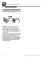
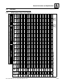
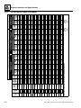


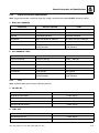

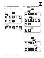
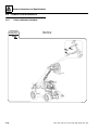
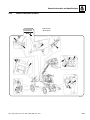

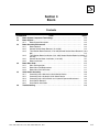


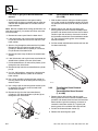


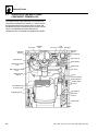
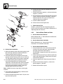
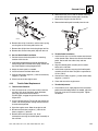


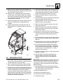

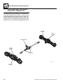
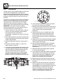
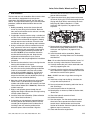
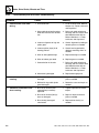
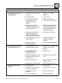

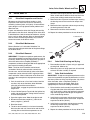
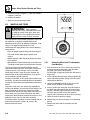
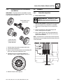
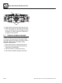

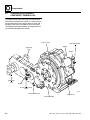


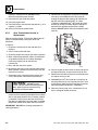
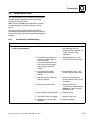


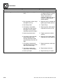
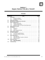
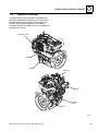
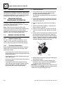


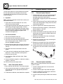

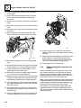
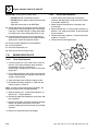


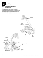

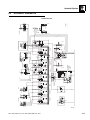
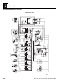
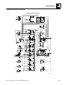
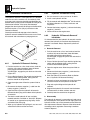
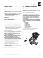

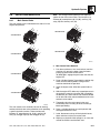

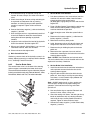
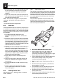


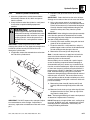

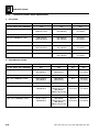
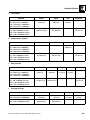
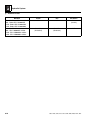


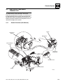

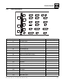

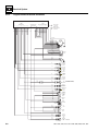


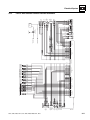
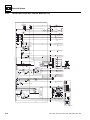
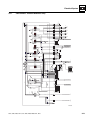


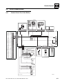

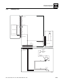
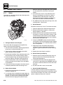
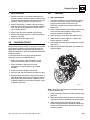
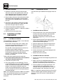
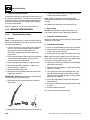
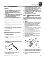
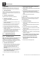
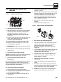


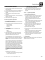


![[Competition Commission Undertaking No [ ] of 2004]](http://vs1.manualzilla.com/store/data/006010311_1-21996dba8872f587e5a78ef073ded048-150x150.png)