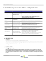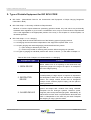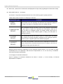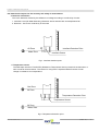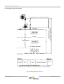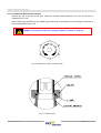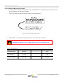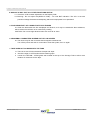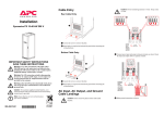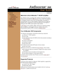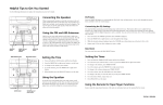
1
INSTRUCTION MANUAL
for PMS (Portable Tank Measuring System)
Portable Oil-Water Interface Detector
and Temperature Gauging
Model T2000-TFC-02
Gas-Tight(Closed) Type
Benefits of T2000-TFC-02
z
z
z
z
z
z
z
z
z
Portable – one unit used for all tanks
Economical and affordable
Cargo contents validation
High Accuracy & Response Performance
Easy Installation & Operation
Easy Maintenance
Environmental Pollution Prevention
Perfect Isolation of Hazardous Gas
Determines Interface, Ullage and
temperature (3 – in – 1)
MODEL : T2000-TFC-02
Portable Tank Measuring System
1. Table of Contents
1. Table of Contents.
2. Useful Measuring Jobs on Deck of Tanker and Applicable Rules.
3. Type of Portable Equipment for IBC BCH CODE.
4. All Kinds of TANKTECH Portable Measuring System.
5. Installation Chart for TANKTECH Portable Measuring System.
6. Three Functions.
7. Specification for Portable Oil/Water Interface Detector.
(Model : T2000-TFC-02)
8. Operating Process for Portable Oil/Water Interface Detector.
(Model : T2000-TFC-02)
9. Troubleshooting for Portable Oil/Water Interface Detector.
(Model : T2000-TFC-02)
<ATTACHMENT>
* Technical Service Manual
TANKTECH CO., LTD
HEAD OFFICE :
1506-2, SONGJEONG-DONG, GANGSEO-GU, BUSAN, 618-270, KOREA
TEL : +82-51-979-1600
FAX : +82-51-979-1601
E-MAIL : [email protected]
http://www.tanktech.co.kr
TKT-TFC-02 (REV. 2-3)
SHEET NO. :
2
Portable Tank Measuring System
2. Useful Measuring Jobs on Deck of Tanker and Applicable Rules
Equipment Type
Function
Ullage level
Closed Type Portable
Oil/Water Interface
Temperature gauging
Detector ( UTI)
Oil-water interface level
Cargo Liquid Sampling
Device
Liquid sampling
Compliance with
SOLAS 1974,CHAPⅡ-2 REGULATION 60 PARAGRAPH 7
IMO, MSC/Circ.551 (IBC BCH CODE)
MARPOL 73/78 ANNEXⅠ-CHAPⅡ- REGULATION 15, (3) (b)
IMO RESOLUTION MEPC.5(XIII) ANNEX 4.
OCIMF, API STANDARD
RESTRICED WITH CLOSED SAMPLING OF LIQUID SAMPLING
Inert Gas Sampling Hose
Oxygen and flammable gas
IMO REQUIREMENT ON TANKER SAFETY AND POLLUTION
& Adapter
concentration measuring
PREVENTION, 1978-RESOLUTION A.446(XI), 6.6
Pressure Gauge
Inert gas press. gauging
Tank Bottom Liquid and
Sediments Checking
Device
IMO REQUIREMENT ON TANKER SAFETY AND POLLUTION
PREVENTION, 1978-RESOLUTION A.446(XI), 6.6(b)
Tank bottom dryness,
IMO REQUIREMENT ON TANKER SAFETY AND POLLUTION
& sediment checking
PREVENTION, 1978-RESOLUTION A.446(XI) 4.4.4
MARPOL 1973/78 ANNEX I, REGULATION 13b(3)
Shut On/Off Valve
Vapor lock Installation of
portable tank measuring sys.
SOLAS 1974,CHAPⅡ-2 REGULATION 60, PARAGRAPH 7
(REQUIREMENT OF CLOSED ULLAGE SYSTEM)
MARPOL 1973/78 ANNEX I-CHAP II-REGULATION 15, (3) (B) AND
SOLAS 1974,CHAPⅡ-2 REGULATION 62, PARAGRAPH 17
z IMO MEPC.5(XIII)
ANNEX 4
SPECIFICATION FOR OIL/WATER INTERFACE DETECTORS
The instrument should be capable of providing a rapid and accurate determination of the oil/water interface
in slop tanks and/or tanks where the separation of oil and water is effected and from which it is intended to
discharge effluent direct the sea.
z MARPOL 73/78
Chap. -Ⅱ Reg. 15, 3 (b)
Effective oil/water interface detectors approved by the Administration shall be provided for a rapid and
accurate determination of the oil/water interface in slop tanks and shall be available for use in other tanks
where the separation of oil and water is effected and from which it is intended to discharge effluent direct to
the sea.
TKT-TFC-02 (REV. 2-3)
SHEET NO. :
3
Portable Tank Measuring System
3. Type of Potable Equipment for IBC BCH CODE
z
IBC Code : (International Code for the Construction and Equipment of Ships Carrying Dangerous
Chemicals in Bulk)
z
IBC Code-Chap. 17-Summary of Minimum Requirements
Mixtures of noxious liquid substances presenting pollution hazard only and which are provisionally
assessed under regulation 3 (4) of Annex II of MARPOL 73/78, may be carried under the requirements
of the code applicable to the appropriate position of the entry in this chapter for ‘noxious liquids, not
otherwise specified’.
z
IBC Code-Chap. 13-1.3.1 Gauging
13.1.1 Cargo tanks should be fitted with one of the following types of gauging devices
13.1.2 Gauging devices should be independent of the equipment required under 15.19
13.1.3 Open gauging and restricted gauging should be allowed only where:
1) open venting is allowed by the code; or
2) means are provided for relieving tank pressure before the gauge is operated.
13.1.4 Types of gauging for individual products are shown in column “j” in the table of Chapter 17.
Table of IBC Code- Chapter 13 Instrumentation-13.1 Gauging
Equipment Type
Function
1. OPEN DEVICE
Which makes use of an opening in the tanks and may
expose the gauge to the cargo of its vapour. An example of
this is the ullage opening.
2. RESTRICTED
DEVICE
Which penetrates the tank and which, when in use, permits
a small quantity of cargo vapour or liquid to be exposed to
the atmosphere. When not in use, the device is completely
closed. The design should ensure that no dangerous
escape of tank contents (liquid of spray) can the place in
opening the device.
3. CLOSED DEVICE
Which penetrates the tank, but which is part of a closed
system and keeps tank contents form being released.
Examples are the float-type systems, electronic probe,
magnetic probe and protected sight glass. Alternatively an
indirect device which does not penetrate the tank shell and
which is independent of the tank may be used. Examples
are weighing of cargo, pipe flow meter.
TKT-TFC-02 (REV. 2-3)
SHEET NO. :
4
Portable Tank Measuring System
z
BCH Code : (Code for the Construction and Equipment of Ships Carrying Dangerous Chemicals in Bulk)
z
BCH CODE CHAP-III
C-Gauging
3.9 General : Cargo tank should be fitted with one of the following types of gauging devices :
Table of BCH Code- Chapter III C-Gauging 3.9 General
Equipment Type
Function
1. OPEN
DEVICE
Which makes use of an opening in the tank and may expose the gauge to
the cargo or its vapour. An example of this is the ullage opening.
2. RESTRICTED
DEVICE
which penetrates the tank and which, when in use, permits a small quantity
of cargo vapour or liquid to be exposed to the atmosphere. When not in
use, the device is completely closed. The design should ensure that no
dangerous escape of tank contents (liquid or spray) can take place in
opening the device.
3. CLOSED
DEVICE
which penetrates the tank, but which is part of a closed system and keeps
tank contents from being released. Examples are the float-type systems,
electronic probe, magnetic probe and protected sight-glass.
4. INDIRECT
DEVICE
which does not penetrate he tank shell and is independent of the tank. An
indirect measurement for determining the amount of cargo is used such as
weighing of cargo, pipe flow meter, etc.
Gauging devices should be independent of the equipment required under 4.1 & 4.2 except for ships
constructed prior to 27 September 1982 where the requirements of 4.1 & 4.2 are met by a shutdown
valve which operates automatically.
3.10 Gauging for individual substances
Types of gauging for individual substances are shown in column “j” of the summary of minimum
requirements in chapter VI.
TKT-TFC-02 (REV. 2-3)
SHEET NO. :
5
Portable Tank Measuring System
4. All Kinds of TANKTECH Portable Measuring System
O
N
OFF
POR TABLE OIL/WA TE R IN TERFAC E DE TE CTOR
D ISP LAY
G AS : I NTER MITT ENTBEEP
O IL : F RE QUEN T BEEP
W ATER : CON TINU OU S BEEP
ON
0062/ 05
ON
OFF
MODEL
T200 0-TFC-01
MFG. NO
O FF
MFG. DATE
M ADE N
I K OREA
ON
OFF
GAS : INT ERMITT ENTBEEP
OIL : FRE QU ENT BEEP
WAT ER : C ONTI NUOU S BEEP
G AS : I NTER MITT ENTBEEP
O IL : F RE QUEN T BEEP
W ATER : CON TINU OU S BEEP
0062 /05
0062 /05
L IG H TO N
L IG H TO N
MODEL
T2 000 -TFC-02
MODEL
T2 000-T FS-01
MFG . NO
MFG . DATE
MFG . NO
MFG . DATE
ON
O N
MAD E IN K OREA
M ADE IN KOREA
N
OFF
O
TKT-TFC-02 (REV. 2-3)
ON
OFF
SHEET NO. :
6
Portable Tank Measuring System
5. Installation Chart for TANKTECH Portable Measuring System
Portable Oil/Water
Interface Detector
Portable Oil/Water
Interface Detector
Portable Oil/Water
Interface Detector
Gas-tight Type
Gas-tight Type
Restricted Type
T2000-TFC-01
T2000-TFC-02
T2000-TFS-01
TVC-01
Cargo Liquid
Sampling Device
Cargo Liquid
Sampling Device
T2000-TSS-01
T2000-TSS-02
Pressure Gauge
T2000-TPG-01
TVC-02
Tank Bottom Liquid &
Sediments Checking Inert Gas Sampling
Device
& Adaptor
T2000-TLS-01
T2000-TOS-01
TVC-04
6. Three Functions
1. Detection of Ullage
2. Detection of Interface
3. Temperature measurement
TKT-TFC-02 (REV. 2-3)
SHEET NO. :
7
Portable Tank Measuring System
CLOSED TYPE PORTABLE OIL/WATER INTERFACE DETECTOR
FOR ULLAGE, OIL/WATER INTERFACE, TEMPERATURE GAUGING
6. Specification for Portable Oil/Water interface Detector
7. Specification for Portable Oil/Water Interface Detector
7-1. General Description
TANKTECH's Portable Oil/Water Interface Detector, T2000 series offer the total solution for management
of cargo in tanks. This device can detect and measure the Ullage, Oil/Water Interface and Temperature
of cargo at the same time.
7-2. Model : T2000-TFC-02
Accuracy of ullage, interface detection
±2 mm
Indication of level divided
by ullage and interface
Visible and Audible
Tape length
15M / 30M /40M
Tape graduation
Metric
Tape resolution
1 mm
Diameter of probe
34 mm
Minimum detectable level
8 mm
Ambient temperature range
-20℃ to 70℃
Temperature sensor measurement range
-20℃ to 110℃
Temperature measurement resolution
0.1℃
Accuracy over calibration range
±0.1℃( 0℃ to 60℃ )
Temperature reading mode
℃(Celsius) or ℉
LCD display
4-7 Segment
Ball valve coupling
(Top mounting of model : TVC-02 )
PF 2-1/4” TAP
Weight
8.1 kg / 30M
Overall dimensions
(height×width×thickness)
APP. 585×346×150 mm
Battery
9 Volt (MODEL : MN1604)
Intrinsically safe type
Ex ia IIB T4
7-3. Material
MODEL : T2000-TFC-02 ( Body ) -----------------
:
Aluminum casting ( JIS – AC4C-T6 )
7-4. Coating
IN / OUT SIDE ----------------------------------------- : Epoxy nylon coating
COLOR -------------------------------------------------- : Black
THICKNESS ( IN/OUT SIDE ) --------------------- : 80mic.
TKT-TFC-02 (REV. 2-3)
SHEET NO. :
8
Portable Tank Measuring System
CLOSED TYPE PORTABLE OIL/WATER INTERFACE DETECTOR
FOR ULLAGE, OIL/WATER INTERFACE, TEMPERATURE GAUGING
8. Operating Process for Portable Oil/Water Interface Detector
8-1. General description
Thank you for purchasing TANKTECH Portable Tank Measuring equipment.
Our products will make marine cargo tank gauging more efficiently.
Our PMS reflects the three requisites for good management: economical price, user's safety, and
environmentally friendly.
Before using our products use, Please carefully read this manual. By doing so, proper handling
of the equipment can be ascertained.
8-2. About mark of the manual
This manual is written with [Warning] and [Caution] markings. These are important for a safe operation.
These precautions stress the important matter for the prevention of the physical accident and possible
damage to the equipment.
Warning :
When wrong use of equipment may cause body harm to user.
Caution :
When wrong use of equipment may cause damage to the set.
8-3. Application for model : T2000-TFC-02
Model : T2000-TFC-02
TKT-TFC-02 (REV. 2-3)
SHEET NO. :
9
Portable Tank Measuring System
8-4. Location & Function of Controls
1. Carrying Handle
2. Tape Reading Window.
3. Cleaning Adaptor : When rewinding the tape from the tank, to clean tape, rotate this wheel clockwise to the
arrow indicates “ON”. When letting down the probe into the cargo tank, knob show be
turned towards the arrow indicating “OFF”.
4. Rotating handle & push stopper for measuring and rewinding
5. Tape Reading Point (Ullage Read Out Point)
6. Sounding Tape : Non-corrosive tape scale coated by ETFE
7. Buzzer : Audible & distinguishable sound of Gas, Oil & Water
8. LCD Display
9. Display Panel
10. Power Switch
11. Tape Protection Device
12. Sensor Probe
13. Frame (Storage Barrel)
14. Grounding clamp for static discharge
TA NKTECH
Fig 1. Location & Function
TKT-TFC-02 (REV. 2-3)
SHEET NO. :
10
Portable Tank Measuring System
8-5. Temperature display mode selector switch.
Also temperature display can be selected from two mode, ℃ and ℉, by the inside slide switch. If display
mode changing is required, loosen the all screws of front panel and you will find the slide switch.
The temperature display mode should be changed in non-hazardous area.
C / F SELECTION S/W
DIP 2
TANKTECH
Fig 2. Select S/W for Temperature
8-6. Low battery warning.
When the battery is almost used up and it have to be exchanged, a warning is turned on and off repeatedly
in left side of first line as Fig 3. For the accurate measurement, it is desirable that the battery is replaced
immediately after the warning is displayed.
The battery should be replaced in non-hazardous area.
Fig 3. Low battery warning
TKT-TFC-02 (REV. 2-3)
SHEET NO. :
11
Portable Tank Measuring System
8-7. Tape
The tape of T2000 series consist of steel tape and two electric wires. Also, they are coated with ETFE. This
ETFE is a kind of teflon and not corroded by almost all kinds of chemical as well as crude oil.
The electric wires are used for transferring the data acquired by sensors to the display part on the deck.
And the electric power for sensors travels to the probe through the steel tape. Also, the steel tape is strong
enough to bear the live load of probe. Therefore it has the function as protector of the electric wires from
breaking.
Fig 4. Detail electric wire & Tape
TKT-TFC-02 (REV. 2-3)
SHEET NO. :
12
Portable Tank Measuring System
8-8. Detection Principles for the accuracy and safety of measurement
1. General
Portable oil/water interface detector of TANKTECH is a portable tank measuring Instrument to detect the
Ullage, the interface and the temperature. User can know the surrounding environments of the sensor
probe and the temperature by the beep and the indication of the LCD.
User is able to measure the depth of the oil tank by the reading of the measuring tape too.
The measurement of the Ullage and the oil/water interface is used the ultrasonic sensor and the conductive
bar, the beeps are indicated the surrounding environments of the sensing probe. Measure continuously the
oil temperature in tank and indicate the temperature on LCD.
The sources is used the DC 9V alkaline battery.
Fig 5. LCD display
Gas Zone
Oil Zone
8mm
2. Detection of Ullage
This is the detection method by the difference of ultrasonic receiving signal according to acoustic
impedance.
1. Ullage Level (Gas-Oil Boundary) Detection Device : Ultrasonic Sensor
2. Detection : Be determined the output of the receiver sensor, according to the acoustic impedance of the
oil and the gas. The medium is between the transmitter and the receiver
Ullage Detection Point
Ultrasonic Sensor
Fig 6. Ullage detection point
TKT-TFC-02 (REV. 2-3)
SHEET NO. :
13
Portable Tank Measuring System
Oil Zone
Water Zone
8mm
8-8. Detection Principles for the accuracy and safety of measurement
3. Detection of Interface
This is the detection method by the difference of voltage according to conductivity of water.
1. Interface Level (Oil-Water Boundary) Detection device Interface bar and temperature bar
2. Detection : Use to the conductivity of the water
Interface Detection Point
Interface Sensor
Fig 7. Interface detection point
4. Temperature sensor
The PMS tape uses the PT100Ω RTD (Resistance Thermometer Device) instead of the thermistor or
semi-conductor thermal sensor. The reason for using RTD is explained below first with a linear
change in resistance over temperature.
8mm
Gas Zone
Oil Zone
Temperature Detection Point
Temperature Sensor
Oil Zone
Water Zone
Fig 8. Temperature detection point
TKT-TFC-02 (REV. 2-3)
SHEET NO. :
14
Portable Tank Measuring System
8-9. Reading Ullage and Interface
G AS : IN T ER MITTENT BEEP
O IL : F REQ UENT BEEP
W AT ER : CO NT INUOUS BEEP
MODEL
MFG . NO
MFG . DA TE
ULLAGE READ OUT POINT(DATUM LINE)
T2000−TFC−02
TANKTECH
Tank top
CUSTOMER SUPPLY
H1
H2
320
M ADE IN K OREA
Gas zone
Ullage
Temperature
H3 = CARGO TANK DEPTH
ON
TANKTECH SUPPLY
NIGHT ON
Oil zone
Oil Water Interface
Water zone
CARGO TANK BOTTOM
DIMENSION
MODEL
TVC−02
(UNIT : mm)
I.D
H1
H2
H3
50
*
180
H3=H+H1+H2+320
REMARK
1. * FILL OUT BLANK BY CUSTOMER SCOPE
2. DIMENSION H2 IS WITHOUT GASKET(Gasket is Customer Scope)
Fig 9. Reading Ullage & Interface
TKT-TFC-02 (REV. 2-3)
SHEET NO. :
15
Portable Tank Measuring System
8-10. Installation & Measurement method
Remove the cap of the shut on-off valve, Install the oil/water interface detector at 2" shut on-off valve of
TANKTECH CO. LTD.
When sensing part descend by reel, display part emits beep and indicates the surrounding environment of
the oil storage tank on the LCD.
MODEL TVC-02 Shut On/Off valve (Gauging Station) installed on tank top.
Fig 10. Direction for Open & close of cap
Fig 11. Detail of seal
TKT-TFC-02 (REV. 2-3)
SHEET NO. :
16
Portable Tank Measuring System
8-10. Installation & Measurement method
1. If user wants to measure the environment of the oil storage tank by equipment, has to ground with the
grounding cable at the tank after installation.
Connect the grounding cable at the tank before removing equipment.
Fig 12. Connect the grounding cable
2. Power switch on, check the initial state of the LCD screen and "BAT" indication.
Indicated low battery on LCD, change battery only in non-hazardous area.
Table of Separate zone
Intermittent beep
Frequent beep
Continuous beep
TKT-TFC-02 (REV. 2-3)
Position of detection
Beep
LCD Indication
Gas zone
--- --- --- ---
GAS
Oil zone
----------
OIL
Water zone
------------------
WATER
SHEET NO. :
17
Portable Tank Measuring System
8-10. Installation & Measurement method
* Measurement of the Ullage and the Oil/Water Interface
3. Toggle switch on, indicate "GAS", the buzzer emits intermittent beeping sound.
Fig 13. LCD display
4. Pull the Deck Valve lever to open position (in parallel with pipe).
OPEN
CLOSE
OPEN
CLOSE
Fig 14. Open handle position
5. Pull the Deck Valve lever to open position (in parallel with pipe).
Fig 15. Reel handle breaker
TKT-TFC-02 (REV. 2-3)
SHEET NO. :
18
Portable Tank Measuring System
6. Lower the sensor until it touches the cargo. Display will change to "OIL" on LCD and emit frequent beep,
start reading the scale through transparent window. The correct reading is above the bar.
RE W
IND
TANKTECH
Fig 16. Arrow shows the direction to rewind
7. Pull the tape up and down slightly to determine the exact reading point on the tape.
8. Further down in the slop tank as it senses water, display changes to "WATER" on LCD and buzzer emits
continuous beep start reading the scale the transparent window.
Please read out above line of tape reading bar.
Fig 17. View of Ullage, Interface read out point
TKT-TFC-02 (REV. 2-3)
SHEET NO. :
19
Portable Tank Measuring System
* Temperature measurement
9. Temperature measurement is simultaneous and continuous, without the need to switch over.
10. The value is in degree Celsius(℃) on LCD as our standard supply. However if user wants the reading to be
in degree Fahrenheit(℉), he may request for change of temperature mode in the purchase order.
* Rewinding work after measurement
11. Turn the wiper knob to cleaning position indicated by arrow. Wind the reel slowly in anti-clockwise
direction. Check cleaning state of measuring tape through transparent window.
※ RESET POISITION AFTER CLEANING.
Fig 18. Tape Cleaner
12. Tape protection device from the cut by careless valve closing.
Sensor probe will be inserted to the protection pipe during tape rewinding and this protection device
will be completely protected by the tape.
SENSOR PROBE
STORAGE BARREL
TAPE PROTECTION DEVICE
FIX GUIDE
TVC-02 BALL VALVE
Fig 19. Tape protection device
TKT-TFC-02 (REV. 2-3)
SHEET NO. :
20
Portable Tank Measuring System
CLOSED TYPE PORTABLE OIL/WATER INTERFACE DETECTOR
FOR ULLAGE, OIL/WATER INTERFACE, TEMPERATURE GAUGING
9. Troubleshooting for Portable Oil/Water Interface Detector
SYMPTOMS
1. DEAD SET – No indication on the display, no beeping sound.
A. Check battery – Voltage above 6V ?
B. If yes – Check the fuse at Display PCB (Left of the LCD Display).
C. If fuse is good – Check Power Supply Regulator circuit and shut-circuit the wire and tape(Include probe).
D. If fuse is blown – Always replace genuine spare parts from TANKTECH. We will not be responsible if
alternative parts other than those of our supply are used.
2. DISPLAY is reading Temperature – No beeping sound.
A. Check buzzer and connecting cables with Ohm meter.
B. If continuity is OK, check cables and connectors.
C. If the reading is infinity, check buzzer and replace buzzer.
D. Check cables and connector.
3. DISPLAY reads “ERROR”.
3.1 CHECK CABLE CONNECTIONS TO THE PROBE
i. Remove the Red and Yellow cable from the connector at Display PCB.
ii. Check resistance between Red and Yellow cable with Ohm meter. Reading at ( )KΩ.
iii. Reverse the Resistance probe (from Meter) and check again the Ohm reading at ( )KΩ.
3.2 If both readings indicate infinity, there is a possibility that the tape is broken.
3.2.1 Remove the probe connection.
3.2.2 Check continuity between wire at display connector and the probe to verify this
assumption.
3.3 If any one of the cables is open circuit (infinity reading), proceed to confirm tape.
3.3.1 Check the tape connections from the HUB to confirm that tape is cut.
3.4 If the tape is confirmed cut, proceed to replace the tape. (see tape replacement process).
3.5 If the tape is OK. Proceed to check gland cable connection between connection HUB and display
side. Slacken the tape winding to the hub by turning lever clockwise against the ARROW.
3.6 Check the soldered connections inside the HUB: Red, Yellow and Black wires.
3.6.1 If the connections are broken, solder the wires as: Red top, Black middle and
Yellow bottom (Scale facing).
3.6.2
3.6.3
If the wires are wrong, swap positions and test.
Replace shrinking tubes (3mm dia. for wires and 13mm dia. for tape) before
soldering.
3.7 To remove wire from connector, push the latch pin with jewel screwdriver and pull out wire from
plastic connector.
3.8 Use Ohm meter to check continuity between tape wires and connector.
TKT-TFC-02 (REV. 2-3)
SHEET NO. :
21
Portable Tank Measuring System
4. DISPLAY IS DIM – BUT ALL OTHER FUNCTIONS ARE OK.
4.1 Check the LCD Contrast Adjustment on the Display PCB.
4.2 Warning ! Do not adjust VR1(DISPLAY PCB) – for LOW BAT indication. The VR1 is set with
precision Voltage Generator and adjusting without this equipment is not permitted!
5. POOR SENSITIVITY OF CONDUCTIVITY ELECTRODES
5.1 Clean the electrodes with fine sandpaper and alcohol, as it may be coated with alien substance,
which causes the reduction of its conductivity reading.
CAUTION ! Do not use high abrasive tools such as a file to clean.
6. ABNORMAL CHARACTERS APPEAR ON THE LCD SCREEN
6.1 The cause may be due to intense electromagnetic interferences.
・ Turn off the power and wait for 3 seconds to reset the system, then on again.
7. TAPE DOES NOT GO DOWN INTO THE TANK
7.1 There is too much friction between the tape and wiper.
♦
♦
Check the wiper in OFF Position before lowering tape.
Loosen the TEFLON / VITON gland seal located at the top of the Storage Tube to allow more
freedom of movement for the tape.
TKT-TFC-02 (REV. 2-3)
SHEET NO. :
22