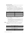
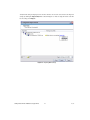
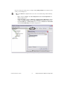
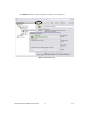
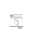
1
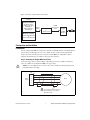
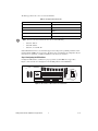
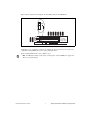
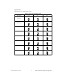
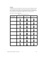
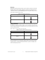
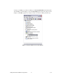
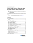
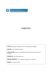
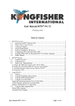
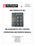
GETTING STARTED P7000 Series Stepper Drives This manual helps you quickly install and configure the P7000 series stepper drives and stepper motors. It assumes you have already installed your National Instruments motion controller and driver software. The driver CD installs the NI Measurement & Automation Explorer (MAX) configuration files and documents referenced in this manual. You can find all the software, files, and documents at ni.com/motion/stepper. Additionally, this manual assumes you are using either the NI Universal Motion Interface (UMI)-7764 or NI UMI-7774/7772 and have the appropriate 68-pin cable for connecting to your NI motion controller. Refer to the NI Stepper Motion System Selection Guide at ni.com/motion/stepper for assistance. For specifications or installation questions about your NI motion controller or NI UMI, refer to the appropriate user manual. Contents What You Need to Get Started ............................................................................................................ 2 Hardware...................................................................................................................................... 2 Software ....................................................................................................................................... 2 Configuration and Installation ............................................................................................................. 3 Configuration ............................................................................................................................... 3 Step 1: Connecting the Stepper Motor to the Drive............................................................. 3 Step 2: Configuring the DIP Switches................................................................................. 4 Step 3: Connecting Power to the P7000 Drive .................................................................... 14 Step 4: Configuring the P7000 Drive with the Serial Port (Optional)................................. 15 Step 5: Installing the P7000 Tools (Optional) ..................................................................... 17 Step 6: Testing the Motor With the P7000 Tools (Optional) .............................................. 21 Step 7: Configuring the NI UMI.......................................................................................... 22 Measurement & Automation Explorer (MAX) Configuration .................................................... 23 Step 8: Configuring Your NI Motion Controller ................................................................. 23 Step 9: Testing the Motor Using MAX ............................................................................... 27 Configuring Moves with NI Motion Assistant (Optional)................................................................... 27 Exporting to LabVIEW................................................................................................................ 28 Troubleshooting the P7000 Series Stepper Drive................................................................................ 29 Specifications....................................................................................................................................... 30 Environment................................................................................................................................. 30 Safety ........................................................................................................................................... 30 Electromagnetic Compatibility .................................................................................................... 30 CE Compliance ............................................................................................................................ 31 Online Product Certification........................................................................................................ 31 Environmental Management........................................................................................................ 31 Where to Go for Support ..................................................................................................................... 32 © National Instruments Corporation 1 Getting Started with the P7000 Series Stepper Drives What You Need to Get Started You need the following items to get started if you are using the P7000 drive with an NI 73xx motion controller. Note If you are using the NI 9512 C Series drive interface module with the P7000 series stepper drive, refer to the Connecting to P7000 Series Stepper Drives section of the Getting Started with NI 951x C Series Modules and LabVIEW, available from ni.com/manuals. Follow the steps in this document through Step 6: Testing the Motor With the P7000 Tools (Optional), then use the Getting Started manual to connect the module to the drive. Hardware ❑ NI 7330/7340/7350 motion controller ❑ NI UMI-7764 or NI UMI-7774/7772 ❑ Power supply for the NI UMI: – +5 V if using the NI UMI-7764 – +24 V if using the NI UMI-7774/7772 ❑ 68-pin cable to connect your NI UMI and motion controller ❑ P70360 or P70530 stepper drive ❑ P7000 direct connect cable appropriate for the NI UMI you are using ❑ DC power supply if using the P70530 stepper drive ❑ NI or third-party stepper motor ❑ NI or third-party encoder (optional) ❑ RS-232 serial communication cable for P7000 drives (optional) Software ❑ NI-Motion 7.6 or later driver software ❑ One of the following software packages and documentation: – LabVIEW 7.1.1 or later – LabWindows™/CVI™ 7.0 or later – Microsoft Visual C++ 6.0 or later – Microsoft Visual Basic 6.0 or later ❑ NI Motion Assistant 2.2 or later (optional) ❑ P7000 Tools configuration software (optional) Note The RS-232 serial configuration cable and P7000 Tools configuration software are required only if you are using a third-party motor. If you are using an NI stepper motor, you can perform configuration using only the DIP switches on the drive. Getting Started with the P7000 Series Stepper Drives 2 ni.com Figure 1 shows the required hardware and software. Host PC NI Motion Software NI-Motion Driver NI Motion Assistant LabVIEW (or Other Application Environment) 68-Pin Cable NI UMI-7764 or NI UMI-7774/7772 P7000 Direct Connect Cable NI Motion Controller P70530 DC Drive or P70360 AC Drive M NI PCI-733x/734x/735x or NI PXI-733x/734x/735x Figure 1. Required Hardware and Software for NI 73xx Motion Controllers Configuration and Installation Configuration You can configure the P7000 series stepper drives using the external DIP switches or through the RS-232 port. If you have an NI stepper motor, you can configure the drive and motor using only the DIP switches. If you have a third-party motor, you must use the P7000 Tools configuration software. Complete the following steps to configure your stepper drive and motor: Step 1: Connecting the Stepper Motor to the Drive Connect the stepper motor as shown in Figure 2. The NI stepper motors are highly recommended, as they are optimized to work with the P7000 series stepper drives. Caution Do not hot-plug the motor connector. Also, avoid “whiskers” from stranded phase leads protruding from the motor plug. J6 1 2 Motor Power 3 4 5 A– A+ B– Motor B+ Earth GND To avoid electrical shock, motor ground must be connected to protective earth. Figure 2. Connecting the Stepper Motor © National Instruments Corporation 3 Getting Started with the P7000 Series Stepper Drives The NI stepper motor wire color code is shown in Table 1. Table 1. NI Stepper Motor Wire Colors Phase Color A– Orange A+ Black B– Yellow B+ Red PE Green/Yellow Stripe Note To reverse the motor rotation direction, do one of the following: • Switch A– with A+ • Switch B– with B+ • Switch A–, A+ with B–, B+ National Instruments offers several standard stepper motors that provide optimum performance when matched with the P7000 series stepper drive. The motors have a four flying lead configuration. If your motor has six or eight leads, consult your distributor or the factory for assistance. Step 2: Configuring the DIP Switches Configure the DIP switches as follows for proper operation of your P7000 series stepper drive. OFF 8 9A E 345 67 F01 2 Figure 3 shows switches S2–1 through S2–12 in the OFF position for the P70360 drive. 1 2 3 5 4 6 7 8 9 10 11 12 BC D 12 S1 S2 1 12 Figure 3. DIP Switches in OFF Position for P70360 Drive Getting Started with the P7000 Series Stepper Drives 4 ni.com Figure 4 shows switches S2–1 through S2–12 in the OFF position for the P70530 drive. OFF ON 8 9A E 345 67 F01 2 1 1 2 3 4 5 6 7 8 9 1011 12 BC D S1 Motor S2 5 Load 7 2 Step 4 8 9 Smooth Computer Setup S1=0, S2 1-12 = OFF High = OFF, Open Low = ON, Closed 10-12Advanced Figure 4. DIP Switches in OFF Position for P70530 Drive Using Table 4 or 5, set switches S1 and S2-1 to configure the drive for your motor, or use the serial configuration using P7000 Tools if you are using a third-party motor. For the remaining DIP switches, refer to Tables 2 and 3. Note For DIP switch settings to take effect, you must power cycle the P7000 series stepper drive whenever you make changes. © National Instruments Corporation 5 Getting Started with the P7000 Series Stepper Drives Table 2. DIP Switch Positions for Getting Started Motor Selection Step Resolution S1 S2–1 S2–2 S2–3 S2–4 Motor Dependent Motor Dependent ON OFF ON O F F O N Load Inertia Dynamic Smoothing O N 2 3 4 Current Reduction Multistepping Encoderless Stall Detection S2–5 S2–6 S2–7 S2–8 S2–9 S2–10 S2–11 S2–12 OFF OFF OFF OFF OFF OFF OFF OFF O F F O F F 5 O F F 6 O F F 7 O F F 8 O F F 9 O F F 10 O F F 11 12 Table 3. Drive Settings for Getting Started Drive Option Setting Motor selection Motor dependent (refer to Tables 4 and 5 for switch positions) Step resolution 5,000 (refer to Table 6 for switch positions) Load inertia 0–1 (refer to Table 7 for switch positions) Dynamic smoothing Minimal (refer to Table 8 for switch positions) Current reduction Enabled (refer to Table 9 for switch positions) Multistepping Disabled (refer to Table 10 for switch positions) Encoderless stall detection Disabled (refer to Table 11 for switch positions) Getting Started with the P7000 Series Stepper Drives 6 ni.com Motor Selection Table 4 lists the switch settings for P70360-compatible motors. Table 5 lists the switch settings for P70530-compatible motors. Table 4. P70360-Compatible Motor DIP Switch Settings Motor NI NEMA 23 T21NRLC S1 S2–1 1 OFF 34 5 6 E 7 8 9A F01 2 Motor Frame BC D 2 E 7 8 9A BC D 3 E 7 8 9A BC D N31HRLG 4 E 7 8 9A BC D 5 E 7 8 9A BC D 6 E 7 8 9A BC D 0 F01 2 BC D 7 7 8 9A © National Instruments Corporation O F F 1 O F F 1 O F F 1 OFF 34 5 6 Serial configuration using P7000 Tools E Third-party 1 OFF 34 5 6 F01 2 N33HRLG O F F OFF 34 5 6 F01 2 N32HRLG 1 OFF 34 5 6 F01 2 NI NEMA 34 O F F OFF 34 5 6 F01 2 T23NRLC 1 OFF 34 5 6 F01 2 T22NRLC O F F O F F 1 Getting Started with the P7000 Series Stepper Drives Table 5. P70530-Compatible Motor DIP Switch Settings Motor NI NEMA 17 CTP 10 ELF 10 S1 S2–1 D ON 34 5 6 E 7 8 9A F01 2 Motor Frame BC D E ON 34 5 E 7 8 9A BC D F ON E 7 8 9A BC D 2 E 7 8 9A BC D E 7 8 9A BC D E 7 8 9A BC D E BC D 2 O F F 1 O N 1 ON 34 5 6 E 7 8 9A F01 2 1 ON 7 8 9A F01 2 1 BC D 3 O N 1 ON 34 5 6 E 7 8 9A F01 2 O F F 6 BC D 0 F01 2 7 8 9A E O N 1 OFF 34 5 6 BC D 8 1 34 5 N33HRHJ Getting Started with the P7000 Series Stepper Drives O F F OFF 6 F01 2 4 34 5 N32HRHJ Serial configuration using P7000 Tools 1 OFF 6 F01 2 3 34 5 N31HRHJ O N OFF 34 5 6 F01 2 T21NRLH T23NRLH Third-party 1 34 5 T22NRLG NI NEMA 34 O N 6 F01 2 CTP 12 ELF 10 NI NEMA 23 1 6 F01 2 CTP 11 ELF 11 O N O F F 1 ni.com Step Resolution Table 6 lists the step resolution switch settings. Table 6. Step Resolution DIP Switch Settings Resolution S2–2 S2–3 S2–4 200 (Full Step) ON ON ON O N O N O N 400 (Half Step) 2 OFF 4 ON ON O N O N O F F 2 5,000 3 ON 3 OFF 4 ON O F F O N 10,000 2 3 OFF OFF 4 ON O F F O F F 18,000 O N 2 3 ON ON O N O N O N 4 OFF O F F 25,000 2 OFF 4 OFF OFF O F F O F F 25,400 3 O F F 2 3 4 OFF ON OFF O F F O F F O N 2 50,000 ON 3 4 OFF OFF O F F O N © National Instruments Corporation 2 O F F 3 9 4 Getting Started with the P7000 Series Stepper Drives Load Inertia The P7000 series stepper drives eliminate the resonance typical of step motors with high-speed, digital processing of motor electrical activity. To use this feature, you must set three switches based on the load-to-rotor inertia ratio. These switches select the gain parameter the drive uses to stabilize the motor. You can calculate the load inertia by hand or by using the Motioneering sizing software. If you do not know your inertia ratio, set the DIP switches to OFF for a load-to-rotor inertia ratio of 0–1. Table 7 lists the load inertia switch settings. Table 7. Load Inertia DIP Switch Settings Load-to-Rotor Inertia Ratio S2–5 S2–6 S2–7 0–1 OFF OFF OFF O F F 1–1.5 O F F O F F 5 6 7 ON OFF OFF O F F O N 1.5–2.5 O F F 5 6 7 OFF ON OFF O F F O F F O N 5 2.5–5.0 6 7 ON ON OFF O N O N O F F 5.0–7.0 5 OFF O F F 7.0–12.0 6 7 OFF ON O F F 5 6 ON OFF O N 7 ON O F F O N 12.0–20.0 O N 5 6 7 OFF ON ON O N O N O F F 5 20.0–32.0 Getting Started with the P7000 Series Stepper Drives 6 7 ON ON ON O N O N O N 5 10 6 7 ni.com Dynamic Smoothing Dynamic smoothing is a temporal filter (second-order, low-pass) applied to the command sequence to reduce jerk. It helps reduce overshoot and lessens the excitation of mechanical resonance in the system. It filters from slightly below the resonant frequency up to well above resonance to remove spectral content that would be misrepresented in the motor output and may also excite other parts of the machine. Dynamic smoothing is a very powerful feature for achieving maximum torque from the motor. However, it is difficult to optimize and is not necessary for the vast majority of applications. Therefore, National Instruments recommends setting both DIP switches to OFF for minimal smoothing. Table 8 lists the dynamic smoothing switch settings. Table 8. Dynamic Smoothing DIP Switch Settings Dynamic Smoothing S2–8 S2–9 Minimal OFF OFF O F F Moderate O F F 8 9 ON OFF O F F O N Heavy 8 9 OFF ON O F F 8 Aggressive © National Instruments Corporation 11 O N 9 ON ON O N O N 8 9 Getting Started with the P7000 Series Stepper Drives Current Reduction Current reduction reduces drive and motor heating by invoking standby current reduction. When enabled, current reduction cuts motor current to 75 percent of its commanded value 100 ms after receipt of the last step pulse. You can adjust the reduction proportion and delay to other values using the P7000 Tools configuration software. When current reduction is enabled, the motor holding torque is reduced. Do not enable it for applications that require full holding torque when the motor is stationary. Table 9 lists the current reduction DIP switch settings. Note Current reduction is enabled when switch S2–10 is OFF. Table 9. Current Reduction DIP Switch Settings Current Reduction S2–10 Enabled OFF O F F 10 Disabled ON O N Getting Started with the P7000 Series Stepper Drives 12 10 ni.com Multistepping Multistepping is similar to dynamic smoothing, except it is a much more aggressive use of the filter. Typically, it results in a filter that begins to roll off two octaves below the resonant frequency. This is intended for use with coarse resolution (full/half-step input pulses) to smooth large steps into a continuous train of microsteps. Disable multistepping if you are not using full or half step resolution. Table 10 lists the multistepping switch settings. Table 10. Multistepping DIP Switch Settings Multistepping S2–11 Enabled ON O N Disabled 11 OFF O F F 11 Encoderless Stall Detection The P7000 series stepper drive is uniquely designed to sense the motor shaft position at all times. The drive monitors the commanded position and compares it to the actual position. As with any two-phase step motor, when the shaft position and commanded position are greater than two full steps apart, a stall is detected, and the drive faults. Table 11 lists the encoderless stall detection switch settings. Table 11. Encoderless Stall Detection DIP Switch Settings Encoderless Stall Detection S2–12 Enabled ON O N Disabled 12 OFF O F F 12 Encoderless stall detection uses an internal motor model for stall detection. Motors listed in Tables 4 and 5 work well with encoderless stall detection. Third-party motors may not work as well, as the algorithm is subject to constraints. National Instruments makes no guarantees of reliability of this feature when using third-party motors. © National Instruments Corporation 13 Getting Started with the P7000 Series Stepper Drives Step 3: Connecting Power to the P7000 Drive Connect either AC or DC input power to your P7000 series stepper drive. If you are using the P70360 drive, connect AC power as shown in Figure 5. Refer to Table 12 for DC power connector pin descriptions. If you are using the P70530 drive, connect DC power as shown in Figure 6. Refer to Table 13 for DC power connector pin descriptions. Connecting AC Power to the P70360 Caution Do not use J7 as an on/off switch. Hot plugging damages the connector. Table 12. J7 AC Power for 320 VDC Bus Pin Description J7–1 120/230 VAC line J7–2 230 VAC neutral J7–3 120 VAC neutral J7–4 PE (Protective Earth) Connection for a 320 VDC Bus Using 240 VAC J7 AC Power 240 Line 1 240N 2 3 4 PE (Protective Earth) Connection for a 320 VDC Bus Using 120 VAC ~ J7 AC Power 1 Line 2 120N 3 4 PE (Protective Earth) 120 ~ Connecting 240 VAC to pin 3 of AC power connector damages the drive. Figure 5. 320 VDC Bus Connection Refer to the P70360 (AC) High Performance Micro-stepping Drive Reference Guide, available from ni.com/manuals or from the Product Support Package CD in your kit, for 160 VDC bus connection. This configuration is required for third-party motors with 7 to 30 mH inductance. Getting Started with the P7000 Series Stepper Drives 14 ni.com Connecting DC Power J7 DC Power +Bus Gnd PE Figure 6. DC Power Connector Table 13. J7 DC Power Pin J7–1 (+Bus) J7–2 (Gnd) Description Plus power supply terminal 20 to 75 V Negative power supply terminal 5 A max Negative power supply terminal/Bus Gnd is normally earthed Isolated, unregulated (or regulated) power supply Maximum allowable voltage between Bus Gnd (J7–2) and Chassis (J7–3) is 100 V peak J7–3 (PE) Connect to PE (Protective Earth) J7–3 connects to J6–5 inside drive (shield) Note National Instruments recommends using insulated wire ferrules to prevent shorting and add strain relief. Power on your DC or AC power supply. Once powered, the P7000 drive enters a configuration mode that causes the LED to flash and the motor to audibly squeal. This is expected operation, as the drive is measuring the motor windings to optimize its settings. Once complete, the status LED should illuminate green. If it is not, refer to the Troubleshooting the P7000 Series Stepper Drive section. Note The following step is required only if you are using the P7000 Tools configuration software and configuring the drive with the RS-232 port. If you are using an NI stepper motor, you can configure the drive with the DIP switches only and proceed to Step 7: Configuring the NI UMI to configure the NI UMI. Step 4: Configuring the P7000 Drive with the Serial Port (Optional) Connect the RS-232 serial communication cable between the drive and computer COM1 port. You must set the COM1 port to the following settings: • Baud Rate: 19,200 • Data Bits: 8 • Parity: Even • Stop Bits: 1 • Flow Control: None © National Instruments Corporation 15 Getting Started with the P7000 Series Stepper Drives To change your COM port, open the Device Manager, click Ports (COM & LPT), and double-click the desired COM port as shown in Figure 7. Select the Port Settings tab and change the settings as shown in Figure 8. Click OK to apply the new settings. You may close the Device Manager after this step. Figure 7. Selecting the COM1 Port in the Device Manager Getting Started with the P7000 Series Stepper Drives 16 ni.com Figure 8. COM Port Settings Step 5: Installing the P7000 Tools (Optional) Install the P7000 Tools configuration software. You can find the software at ni.com/motion/ stepper. Note If you have a previous version of P7000 Tools on your system, the installation wizard automatically uninstalls it. After the previous version is uninstalled, you must run the installer again to install the new version. © National Instruments Corporation 17 Getting Started with the P7000 Series Stepper Drives Launch the P7000 Tools configuration software. The setup wizard appears as shown in Figure 9. Figure 9. P7000 Setup Wizard Getting Started with the P7000 Series Stepper Drives 18 ni.com Click Next, and the P7000 software searches for connected drives on the COM1 port. Once detected, the product selection dialog appears as shown in Figure 10. You may enter a new name for the drive or leave the default. Click Next. Figure 10. Product Selection © National Instruments Corporation 19 Getting Started with the P7000 Series Stepper Drives In the motor selection dialog, shown in Figure 11, select the NI stepper motor you have connected to the drive. If you are using a third-party motor, select None from the list, click the Motor File Editor button, and enter the motor information. The T23NRLC motor is selected in this example. Click Next. Figure 11. Motor Selection No changes are needed for the mechanical information, command values, or I/O functions dialog boxes. Click Next in each one. Click Finish. Your drive setup is complete. The P7000 Tools configuration software downloads the new configuration data to your drive and performs an initialization process with the motor. You may see a dialog box such as the one in shown Figure 12 when the configuration data is about to download. Click Yes to continue the download process. Figure 12. Motor Type Conflict Getting Started with the P7000 Series Stepper Drives 20 ni.com When the configuration data is downloaded, the drive performs the initialization process with the motor as shown in Figure 13. Click OK. Figure 13. Drive and Motor Initialization Caution The motor shaft rotates when performing the following test. Step 6: Testing the Motor With the P7000 Tools (Optional) Test the motor and P7000 series stepper drive configuration by jogging the motor in the negative and positive directions using the following arrows on the Motion Toolbar. Icon Behavior Description Jog motor negative Jogs the motor in the negative direction at the selected velocity. Jog velocity toggle Selects the active jog velocity for the jog arrow buttons. (L designates low speed; H designates high speed.) Jog motor positive Jogs the motor in the positive direction at the selected velocity. Stop motion Stops all motion. Note The RS-232 serial communication cable between the computer and P7000 series stepper drive is no longer needed, but you can leave it connected. If you are using the NI 9512 C Series drive interface module with the P7000 series stepper drive, refer to the Connecting to P7000 Series Stepper Drives section of the Getting Started with NI 951x C Series Modules and LabVIEW, available from ni.com/manuals, for hardware connection information. © National Instruments Corporation 21 Getting Started with the P7000 Series Stepper Drives Step 7: Configuring the NI UMI Follow these steps to connect and configure your NI UMI. (Refer to Figure 1 for more information about connecting the NI UMI to your stepper drive.) 1. Connect your 68-pin shielded cable between the Motion I/O connector on your NI motion controller and the Motion I/O connector on your NI UMI. 2. Connect the P7000 direct connect cable between the NI UMI and the P7000 series stepper drive. If you are using the NI UMI-7774/7772, connect the cable between the Control connector on the NI UMI and the Command I/O connector on the drive. If you are using the NI UMI-7764, connect the leads from the cable to the correct screw terminal. The leads are labeled with the same signal names as the NI UMI-7764 and can be connected to any axis terminal block. You can connect the ground lead to any ground pin on the NI UMI-7764. Refer to Table 14 for the wire colors. Table 14. Wire Color Code for NI UMI-7764 to P7000 Direct Connect Cable Wire Color Signal Name Blue STEP (CW) Red DIR (CCW) Purple INHIN Orange INHOUT Black GND 3. Configure the NI UMI slide switches. You must set the NI UMI switches to match the polarity configuration for the P7000 series stepper drive, as shown in Tables 15 and 16. 4. Connect power to the NI UMI: • If you are using the NI UMI-7764, connect a +5 V external power supply to the two-position terminal block labeled required inputs. Connect the positive lead of the +5 V power supply to the +5 V terminal, and the negative lead to the digital ground (GND) terminal. • If you are using the NI UMI-7774/7772, connect the positive lead of the +24 V external power supply to the V terminal and the negative lead to the C terminal, then connect the V terminal to the Viso terminal and the C terminal to the Ciso terminal. Note For more information about connecting external power, encoders, and other motion I/O signals, refer to the Universal Motion Interface (UMI) Accessory User Guide and Specifications or National Instruments Universal Motion Interface (UMI)-7774/7772 User Manual and Specifications. Table 15. NI UMI-7774/7772 Switch Settings Fault Enable Active low Active high Table 16. NI UMI-7764 Switch Settings Inhibit Input Inhibit Output Active high Active low Getting Started with the P7000 Series Stepper Drives 22 ni.com Measurement & Automation Explorer (MAX) Configuration Step 8: Configuring Your NI Motion Controller To assist with configuring your NI motion controller, NI provides ready-made configuration files to configure your motion controller with the P7000 series stepper drives. To import these files, launch MAX and select File»Import. The Configuration Import Wizard appears as shown in Figure 14. The MAX configuration files are installed at <NI-Motion>\Configuration, where <NI-Motion> is the location where you installed NI-Motion. In the Import from file dialog box, browse to this directory and select the appropriate file for your motion controller. Table 17 lists the MAX filename to import for each NI motion controller. After selecting the file, click Next. Figure 14. Configuration Import Wizard Table 17. MAX Configuration Filenames for NI Motion Controllers NI Motion Controller Configuration File NI PCI/PXI-7330 <NI-Motion>\Configuration\ 7330 Settings for P7000 Drives.nce NI PCI/PXI-7340 <NI-Motion>\Configuration\ 7340 Settings for P7000 Drives.nce NI PCI/PXI-7350 <NI-Motion>\Configuration\ 7350 Settings for P7000 Drives.nce © National Instruments Corporation 23 Getting Started with the P7000 Series Stepper Drives Verify that the settings being imported are checked. You also can select the device that uses the imported settings by clicking the Import Only link, as shown in Figure 15. After selecting the motion controller for the settings, click Import. Figure 15. Importing MAX Settings Getting Started with the P7000 Series Stepper Drives 24 ni.com You also can change the settings a device is using by clicking Change Settings and selecting the desired settings, as shown in Figure 16. Note The P7000 MAX configuration files are the same as the default settings, with the following changes: • Type is changed to Stepper in the Axis Configuration tab under Axis Configuration in the MAX Configuration tree. • Stepper Loop Mode is changed to Open-Loop and Stepper Steps per Revolution is changed to 5000 in the Stepper Settings tab under Axis Configuration in the MAX Configuration tree. • The Forward, Reverse, and Home Limit switches are changed to Disabled in the Motion I/O tab under Motion I/O Settings in the MAX Configuration tree. Figure 16. Choosing MAX Settings File © National Instruments Corporation 25 Getting Started with the P7000 Series Stepper Drives Click Initialize in MAX to configure the NI motion controller, as shown in Figure 17. Figure 17. MAX Initialize Button Getting Started with the P7000 Series Stepper Drives 26 ni.com Step 9: Testing the Motor Using MAX You will now move the motor using the NI motion controller and MAX. Select the 1-D Interactive panel in the Configuration tree and change the settings to match those shown in Figure 18. Change the axis if you are not using Axis 1. Figure 18. 1-D Interactive Panel Settings Note Limits are disabled with these configuration files. National Instruments recommends enabling limits in your final application. Click Start. Your stepper motor should move at the desired velocity. Configuring Moves with NI Motion Assistant (Optional) NI Motion Assistant is a motion control prototyping utility for quickly developing your motion control application. You can use interactive menus to set up and configure move profiles. Complete the following steps to configure a simple one-axis straight line move using NI Motion Assistant. 1. Launch NI Motion Assistant by selecting Start»All Programs»National Instruments» NI Motion Assistant. 2. Click Add Step. Select Straight Line Move from the Add Step dialog box. 3. Click the1D button to set up a single axis move. Choose the axis you want to control. 4. Click the Position tab. Enter the number of steps or revolutions you want the motor to move. 5. Click Run on the toolbar to execute the move. © National Instruments Corporation 27 Getting Started with the P7000 Series Stepper Drives Exporting to LabVIEW After prototyping your moves using NI Motion Assistant, you can export the move profile to LabVIEW for further motion control system development. To export to LabVIEW, select Tools»Generate Code»LabVIEW Diagram. Figure 19 shows an example block diagram generated from NI Motion Assistant. To execute the code, click the Run arrow in the LabVIEW toolbar. Figure 19. LabVIEW Block Diagram of Motion Assistant Code You have now successfully built a LabVIEW application to move a stepper motor using a P7000 series stepper drive. You are now ready to develop advanced applications. For additional information, refer to ni.com/motion/stepper. Getting Started with the P7000 Series Stepper Drives 28 ni.com Troubleshooting the P7000 Series Stepper Drive Table 18 lists problems you may encounter with the P7000 series stepper drive and their possible causes. Table 18. P7000 Series Stepper Drive Troubleshooting Problem Possible Causes The status LED on the drive is off, blinks, or is red. The power source is not properly connected. Refer to the P70360 or P70530 Reference Guide for detailed LED troubleshooting. The motor does not move using the jog toolbar in the P7000 Tools configuration software. The DIP switches are not properly configured. Motor gets hot when idle. Current reduction is disabled. Motor moves backwards. Refer to Step 1: Connecting the Stepper Motor to the Drive. The P7000 Tools configuration software does not detect the drive. Verify that the drive is connected to the COM1 port on the computer. The DIP switches were changed but the drive was not power cycled. Verify that the COM1 port settings are correct as described in Step 4: Configuring the P7000 Drive with the Serial Port (Optional). Power is not properly connected. Verify that the green LED is on. © National Instruments Corporation 29 Getting Started with the P7000 Series Stepper Drives Specifications Environment Maximum altitude..................................................2,000 m at 25 °C ambient temperature Pollution Degree ....................................................2 Indoor use only. Safety This product is designed to meet the requirements of the following standards of safety for electrical equipment for measurement, control, and laboratory use: • IEC 61010-1, EN 61010-1 • UL 61010-1, CSA 61010-1 Note For UL and other safety certifications, refer to the product label, or visit ni.com/ certification, search by model number or product line, and click the appropriate link in the Certification column. Electromagnetic Compatibility This product is designed to meet the requirements of the following standards of EMC for electrical equipment for measurement, control, and laboratory use: • EN 61326 EMC requirements; Minimum Immunity • EN 55011 Emissions; Group 1, Class A • CE, C-Tick, ICES, and FCC Part 15 Emissions; Class A Note For EMC compliance, operate this device according to printed documentation. Getting Started with the P7000 Series Stepper Drives 30 ni.com CE Compliance This product meets the essential requirements of applicable European Directives as follows: • 2006/95/EC; Low-Voltage Directive (safety) • 2004/108/EC; Electromagnetic Compatibility Directive (EMC) Online Product Certification Refer to the product Declaration of Conformity (DoC) for additional regulatory compliance information. To obtain product certifications and the DoC for this product, visit ni.com/certification, search by module number or product line, and click the appropriate link in the Certification column. Environmental Management National Instruments is committed to designing and manufacturing products in an environmentally responsible manner. NI recognizes that eliminating certain hazardous substances from our products is beneficial to the environment and to NI customers. For additional environmental information, refer to the NI and the Environment Web page at ni.com/ environment. This page contains the environmental regulations and directives with which NI complies, as well as other environmental information not included in this document. Waste Electrical and Electronic Equipment (WEEE) EU Customers At the end of their life cycle, all products must be sent to a WEEE recycling center. For more information about WEEE recycling centers and National Instruments WEEE initiatives, visit ni.com/environment/weee.htm. ⬉ᄤֵᙃѻક∵ᶧࠊㅵ⧚ࡲ⊩ ˄Ё RoHS˅ Ёᅶ᠋ National Instruments ヺড়Ё⬉ᄤֵᙃѻકЁ䰤ࠊՓ⫼ᶤѯ᳝ᆇ⠽䋼ᣛҸ (RoHS)DŽ ݇Ѣ National Instruments Ё RoHS ড়㾘ᗻֵᙃˈ䇋ⱏᔩ ni.com/environment/rohs_chinaDŽ (For information about China RoHS compliance, go to ni.com/environment/rohs_china.) © National Instruments Corporation 31 Getting Started with the P7000 Series Stepper Drives Where to Go for Support The National Instruments Web site is your complete resource for technical support. At ni.com/ support you have access to everything from troubleshooting and application development self-help resources to email and phone assistance from NI Application Engineers. A Declaration of Conformity (DoC) is our claim of compliance with the Council of the European Communities using the manufacturer’s declaration of conformity. This system affords the user protection for electromagnetic compatibility (EMC) and product safety. You can obtain the DoC for your product by visiting ni.com/certification. If your product supports calibration, you can obtain the calibration certificate for your product at ni.com/calibration. National Instruments corporate headquarters is located at 11500 North Mopac Expressway, Austin, Texas, 78759-3504. National Instruments also has offices located around the world to help address your support needs. For telephone support in the United States, create your service request at ni.com/ support and follow the calling instructions or dial 512 795 8248. For telephone support outside the United States, contact your local branch office: Australia 1800 300 800, Austria 43 662 457990-0, Belgium 32 (0) 2 757 0020, Brazil 55 11 3262 3599, Canada 800 433 3488, China 86 21 5050 9800, Czech Republic 420 224 235 774, Denmark 45 45 76 26 00, Finland 358 (0) 9 725 72511, France 01 57 66 24 24, Germany 49 89 7413130, India 91 80 41190000, Israel 972 3 6393737, Italy 39 02 41309277, Japan 0120-527196, Korea 82 02 3451 3400, Lebanon 961 (0) 1 33 28 28, Malaysia 1800 887710, Mexico 01 800 010 0793, Netherlands 31 (0) 348 433 466, New Zealand 0800 553 322, Norway 47 (0) 66 90 76 60, Poland 48 22 328 90 10, Portugal 351 210 311 210, Russia 7 495 783 6851, Singapore 1800 226 5886, Slovenia 386 3 425 42 00, South Africa 27 0 11 805 8197, Spain 34 91 640 0085, Sweden 46 (0) 8 587 895 00, Switzerland 41 56 2005151, Taiwan 886 02 2377 2222, Thailand 662 278 6777, Turkey 90 212 279 3031, United Kingdom 44 (0) 1635 523545 National Instruments, NI, ni.com, and LabVIEW are trademarks of National Instruments Corporation. Refer to the Terms of Use section on ni.com/legal for more information about National Instruments trademarks. Other product and company names mentioned herein are trademarks or trade names of their respective companies. For patents covering National Instruments products/technology, refer to the appropriate location: Help»Patents in your software, the patents.txt file on your media, or the National Instruments Patent Notice at ni.com/patents. © 2007–2009 National Instruments Corporation. All rights reserved. 372324B-01 Jul09