1
Alignment & Troubleshooting
4. Alignment & Troubleshooting
This chapter describes some of the main service procedures including;
- Clearing paper jams
- Using the Diagnostic mode
- How to firmware upgrade
- Troubleshooting. etc.
4.1 Alignment and Adjustments
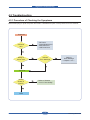
4.1.1 Paper path
Simplex Pass
Duplex Pass
Finisher Pass
MP Feed
Cassette Feed
Service Manual
4-1
Samsung Electronics
Alignment & Troubleshooting
4.1.2 Clearing paper Jam
If a paper jam occurs an error message appears in the LCD display. Find and remove the jammed paper. If
you don’t see the paper, open the covers. Do not use a tweezers, pincers or other metal tools when clearing
a paper jam. This could damage the internal mechanism causing print quality problems or possibly electrical
shock.
■ JAM type
Scanner Unit
DADF Unit
Duplex Jam 1
Duplex Unit
Jam 2
Toner bottle Unit
Cartridge-Transfer Unit
Cartridge-Drum Unit
Jam 1
LSU Unit
Standard tray
Service Manual
Jam 0
4-2
Samsung Electronics
Alignment & Troubleshooting
Registration
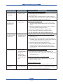
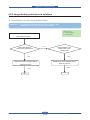
■ Description of JAM type
Case
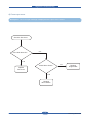
Jam 0
Leading edge of media
does not arrive at
registration within a certain
time after pick-up(If fails at
a time,it tries pick-up again)
Registration
Jam Removal
Registration
Jam Layout
Registration
PickUp
1. Pull out cassette
2. Remove jammed paper
Pick- Up
MP Feed
MP Feed
Pick- Up
MP Feed
Cartridge - Transfer
Pick- Up
MP Feed
Cartridge - Transfer
Cartridge - Transfer
Roller Regi
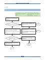
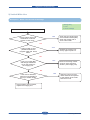
Jam 1
Leading edge of media
does not arrive at Exit
Sensor within a certain time
after registration
1. Open side cover
2. Remove jammed paper
Cartridge
- Transfer
Roller Regi
Registration
Roller Regi
Registration
Roller Regi
Registration
Exit
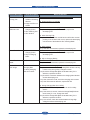
1. Open side cover
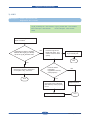
Jam 2
Trailing edge of media does
not leave Exit Sensor within
a certain time after touching
registration
2. Remove jammed paper
OR
1. Remove jammed paper
from exit
1. Open side cover
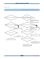
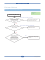
Duplex
Jam 1
Trailing edge of media
leaves Exit Sensor, and
does not arrive at Duplex
Jam1 Sensor
2. Remove jammed paper
OR
1. Remove jammed paper
from exit
Duplex
Exit
Registration
Guide- exit Duplex Duplex
Exit Fuser
Guide- exit Duplex
Duplex
Fuser
exit Duplex
Exit GuideCartridge - Transfer Duplex
Fuser
Guide- exit
Duplex
Cartridge
- Transfer
Fuser
Cartridge
- Transfer
Exit
Exit - Transfer
Cartridge
Exit
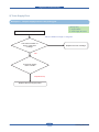
Guide- exit Duplex
Exit
Guide- exit Duplex
Duplex
Jam 1
Duplex
Jam 1
Duplex
Jam 1
Duplex
Guide- exit DuplexJam 1
Guide- exit Duplex
Service Manual
4-3
Samsung Electronics
Alignment & Troubleshooting
4.1.2.1 Tips for avoiding paper jams
By selecting the correct media types, most paper jams can be avoided.
• Ensure that the adjustable guides are positioned correctly.
• Do not overload the tray. Ensure that the paper level is below the paper capacity mark on the inside of the
tray.
• Do not remove paper from the tray while your machine is printing.
• Flex, fan, and straighten paper before loading.
• Do not use creased, damp, or highly curled paper.
• Do not mix paper types in a tray.
• Use only recommended print media.
• Ensure that the recommended side of the print media is facing up in the tray, or facing down in the multipurpose tray.
• If paper jams occur frequently when you print on A5/B5-sized paper: Load the paper into the tray with the
long edge facing the front of the tray. If load the paper this way, printing both sides of the paper (Duplex) is
not supported.
Service Manual
4-4
Samsung Electronics
Alignment & Troubleshooting
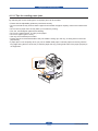
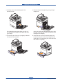
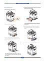
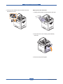
4.1.2.2 Clearing document jams
When an original jams while passing through the DADF, the warming message appears on the display
screen.
1. Remove any remaining pages from the DADF.
Misfeed of exiting paper
2. Open the DADF cover.
1. Remove the remaining documents from the
DADF.
2. Open the DADF cover.
3. Gently remove the jammed paper from the
DADF.
3. Open the document input tray upwards and pull
the document gently out of the DADF.
4. Close the DADF cover. Then reload the pages
you removed, if any, in the DADF.
4. Close the DADF cover and the document input
tray. Then place the documents back in the
DADF.
Service Manual
4-5
Samsung Electronics
Alignment & Troubleshooting
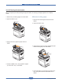
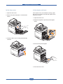
Roller misfeed
4. Remove the paper from the feed area by
carefully pulling.
1. Open the scanner lid.
2. Grasp the misfed paper, and remove the paper
from the feed area by carefully pulling it to the
right using both hands.
1
1
1
5. Close the white document background and the
scanner lid. Then load the removed pages back
into the DADF.
scanner lid
if you do not see the paper in this area, stop and
go to step 3.
1
scanner lid
3. Open the white document background.
Service Manual
4-6
Samsung Electronics
Alignment & Troubleshooting
4.1.2.3 Clearing paper jams
When a paper jam occurs, the warming message appears on the display screen. Refer to the table below to
locate and clear the paper jam.
Message
Location of jam
Paper Jam in tray 1
In the paper feed area (tray 1, optional tray, or
Paper Jam in tray2
multi-purpose tray)
Paper Jam in tray 2(HCF)
Paper Jam in tray3
Paper Jam in MP tray
Paper Jam in exit area
In the paper inside the machine
Paper Jam inside of machine
In the fuser area
Paper Jam at the bottom of duplex path In the duplex unit
Paper Jam at the top of duplex path
Paper Jam inside of duplex path
Paper jam in front of finisher
Paper jammed in the stacker.
Paper jam inside finisher
Paper jam at exit of finisher
Paper jammed in the stacker exit part.
Paper jam inside finisher’s duplex
Paper jammed in the stacker.
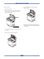
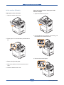
In the tray 1
2. Open the guide in the direction shown.
1. Open the side cover.
Service Manual
4-7
Samsung Electronics
Alignment & Troubleshooting
3. Carefully remove the misfed paper in the
direction shown.
5. Remove the jammed paper by gently pulling it
straight out.
If the paper does not move when you pull, or if
you do not see any paper in this area, stop and
go to step 4.
Once you remove the jammed paper here, open
the side cover and then close it to clear the error
message on the display.
4. Lift the front part of the tray up slightly to release
the tray from the machine.
Service Manual
6. Close the side cover and insert the paper tray.
Lower the rear part of the Tray to align the rear
edge with the corresponding slot of the machine,
then insert it completely.
4-8
Samsung Electronics
Alignment & Troubleshooting
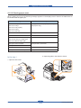
In the optional tray
4. Lift the front part of the tray slightly up to release
the tray from the machine.
1. Open the outer cover in tray 2.
If the paper does not move when you pull, or if
you do not see the paper in this area, stop and
go to step 3.
2. Open the inner cover of tray 2.
5. Remove the paper in the direction shown. To
avoid tearing the paper, pull it out gently and
slowly.
3. Pull the jammed paper out in the direction
shown. To avoid tearing the paper, pull it out
gently and slowly.
6. Insert the paper tray and close the two covers.
If the paper does not move when you pull, or if
you do not see any paper in this area, stop and
go to step 4.
Service Manual
4-9
Samsung Electronics
Alignment & Troubleshooting
In the optional high capacity feeder
3. Pull the jammed paper out, in the direction
shown, pulling gently and slowly in order to avoid
tearing the paper.
1. Open the outer cover of the high capacity feeder.
If the paper does not move when you pull, or if
you do not see any paper in this area, stop and
go to step 4.
2. Open the inner cover of the high capacity feeder.
4. Pull out the optional high capacity feeder.
5. Lift the front part of the tray slightly up to release
the tray from the machine.
Service Manual
4-10
Samsung Electronics
Alignment & Troubleshooting
In the multi-purpose tray
6. Remove the paper in the direction shown. Pull
it out gently and slowly in order to avoid tearing
the paper.
1. If the paper is not feeding properly, pull the
paper out of the machine.
If the jammed paper is not visible, or if the paper
is stuck, stop pulling and continue on to step 5.
2. Open and close the side cover. Printing
automatically resumes.
7. Insert the paper tray and close the two covers.
Service Manual
4-11
Samsung Electronics
Alignment & Troubleshooting
In the paper inside the machine
3. Open the guide in the direction shown and pull
the jammed paper gently out of the machine.
1. Open the side cover.
4. Open and close the front cover to resume
printing.
2. Remove the jammed paper, in the direction
shown.
If you do not see any paper in this area, go to
step 3.
Service Manual
4-12
Samsung Electronics
Alignment & Troubleshooting
In the fuser area
In the duplex unit area
1. Open the side cover.
If the duplex unit is not inserted correctly, paper
jam may occur. Make sure that the duplex unit is
inserted correctly.
2. Remove the jammed paper, in the direction
shown.
1. Open the side cover.
2. Release the guide to pull the jammed paper
easily.
3. Close the side cover. Printing automatically
resumes.
3. Remove the jammed paper.
4. Close the side cover.
Service Manual
4-13
Samsung Electronics
Alignment & Troubleshooting
In the stacker (finisher)
Paper jam inside finisher, Paper jam inside
finisher’s duplex
Paper jam in front of finisher
1. Open the stacker front cover.
1. Open the stacker front cover.
2. Pull the stacker lever 1a down. If necessary, pull
the stacker lever 1b down as well.
2. Press right of 1c lever and then push stacker to
left.
3. Remove the jammed paper.
3. Remove the jammed paper.
4. Slide in the stacker until you hear the sound
‘click’.
5. Close the stacker front cover.
Service Manual
4-14
Samsung Electronics
Alignment & Troubleshooting
Paper jam at exit of finisher
4. Pull up on the stacker lever and then close the
stacker front cover.
1. Gently pull the paper out through the exit area.
2. Close the side cover. Printing automatically
resumes.
3. Remove the jammed paper.
Service Manual
4-15
Samsung Electronics
Alignment & Troubleshooting
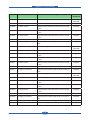
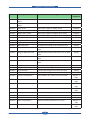
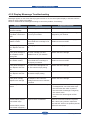
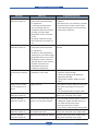
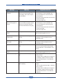
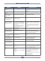
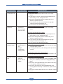
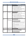
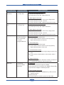
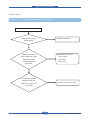
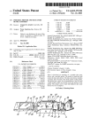
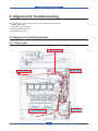
4.1.3 Abnormal Image Printing and Defective Roller
If a mark or other printing defect occurs at regular intervals down the page, it may be caused by a damaged
or contaminated roller. Make sure the repetition interval by consulting the table below.
If the roller is dirty, try to clean it. If the problem is still occurred after cleaning the roller, replace the part
including the defective roller.
NO
Roller
Period
Phenomenon
(mm)
Replace part
1
Pressure Roller
91.1
Offset, Spot, Line Burst
2
T2 Roller
88.0
White and Black Spot, Periodic Banding, Transfer Roller
Rear Side Paper Dirty
3
Registration Roller
59.7
Roll Mark
-
4
Pick-up Roller
72.3
Roll Mark
-
5
Drive Roller
77.8
Periodic Banding, Color Registration
ITB Unit
6
T1 Roller
44.0
White and Black Spot, Periodic Banding
ITB Unit
7
Exit Roller
47.1
Roll Mark, Vertical Scratch
-
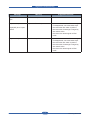
8
OPC Drum
94.3
White and Black Spot, Periodic Banding,
Ghost, Color Registration
Imaging Unit
Charger Roller
44.0
White and Black Spot, Periodic Banding
Imaging Unit
Magnetic Roller (K)
35.3
Periodic Banding
Imaging Unit
Magnetic Roller
(YMC)
35.3
Periodic Banding
Imaging Unit
9
Fuser Belt
127.7
Waving, Offset, Spot, Line Burst
Fuser Unit
10
ITB
785.4
White and Black Spot, Periodic Banding
ITB Unit
Service Manual
4-16
Fuser Unit
Samsung Electronics
Alignment & Troubleshooting
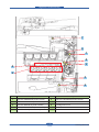
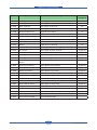
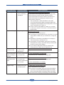
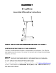
■ Repetitive defect Image check page
Print this page. Align the this page and the printed defect image and find the defective roller.
Start line
Magnetic roller
(CMYK)
Charge roller
T1 roller
Exit roller
Regi roller
Registration Roller
Pick up roller
Drive roller
T2 roller
Pressure roller
OPC Drum
Fuser belt
Service Manual
4-17
Samsung Electronics
Alignment & Troubleshooting
7
9
1
5
2
6
8
3
4
No
Description
No
Description
1
ROLLER-PRESSURE(JC66-01412A)
6
ROLLER-TRANSFER(JC66-01513A)
2
ROLLER-TRANSFER(JC66-01505A)
7
Exit roller
3
ROLLER-REGIIDLE(JC66-01506A)
8
Cartridge Drum unit
4
RUBBER-ROLLER PU(JC73-00216A)
9
Fuser belt
5
ROLLER-DRIVE(JC66-01511A)
Service Manual
4-18
Samsung Electronics
Alignment & Troubleshooting
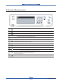
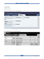
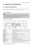
4.1.4 Control Panel overview
1
Machine Setup: Leads you to the machine setup and advanced settings.
2
Job Status: Shows the jobs currently running, queued jobs or completed jobs.
3
Status: Shows the status of your machine.
4
Display screen: Displays the current machine status and prompts during an operation.
You can set menus easily using the touch screen.
5
Numeric keypad: Dials fax number, and enters the number value for document copies or other options.
6
Clear: Deletes characters in the edit area.
7
Redial/Pause: In standby mode, redials the last number, or
in edit mode, inserts a pause into a fax number.
8
On Hook Dial: Engages the telephone line.
9
Interrupt: Stops a job in process to do an urgent copy job.
10
Clear All: Reverts the current settings to the default values.
11
Power Saver: Sends the machine into the power saver mode.
You can also turn the power on and off with this button.
12
Stop: Stops an operation at any time. The pop up window
appears on the screen showing the current job that the
user can stop or resume.
13
Start: Starts a job.
Service Manual
4-19
Samsung Electronics
Alignment & Troubleshooting
4.1.4.1 Introducing the touch screen and useful buttons
Touch screen
Machine Setup button
The touch screen allows for user-friendly operation
of the machine. Once you press the home icon
(
) on the screen, it shows the Main screen.
When you press Machine Setup button, you
can browse current machine settings or change
machine values.
• This button allows you to move to Copy, Fax,
Scan, Stored Documents menu directly.
• Machine Status: Shows the current status of the
machine.
• Admin Setting: Allows an administrator to set up
the machine.
• Usage Page Report:You can print the report on
the amount of printouts depending on the paper
size and type.
• : Shows Help. You can find the explanation by
feature contents.
• Copy: Enters the Copy menu.
• Fax: Enters the Fax menu. (Optional)
• Scan: Enters Scan to Email, NetScan, Scan to
Server menu.
• Stored Documents: Enters the Stored Documents
menu.
• USB: When USB memory is inserted into the USB
memory port on your machine, USB icon shows
on the display screen.
• SmarThru Workflow: Enters the SmarThru
Workflow menu.
(Optional)
• Toner Info.: Shows amount of toner used.
• LCD Brightness: Adjusts the brightness of the
touch screen.
• : You can change the display language.
• : Guides you to remove the USB memory
devices from the machine. Follow the instruction
on the LCD. This icon appears only when you
connect an USB memory module.
• Logout: Logs out from the currently logged in
account.
Service Manual
4-20
Samsung Electronics
Alignment & Troubleshooting
Job Status button
Power Saver button
When you press Job Status button, the screen
shows the lists of currently running jobs, queued
jobs and completed jobs.
When the machine is not in use, save electricity
with the provided power save mode. Pressing this
button puts the machine into power save mode.
If you press Power Saver button for more than two
seconds, a window appears, requesting that you
turn the power off. If you choose Yes, the power is
turned off.
This button can also be used to turn the button on.
Status
Off
• The machine is not in the power
save mode.
• Current Job tab: Shows the list of jobs in progress
and pending.
• Completed Job tab: Provides the list of completed
jobs.
• Active Notice tab: Displays any error codes that
have occurred.
• No.: Gives the order of jobs.
• Job Name: Shows job information like name and
type.
• Status: Gives the current status of each job.
• User: Provides user name, mainly computer
name.
• Job Type: Displays details of the active job, such
as job type, recipient phone number and other
information.
• Detail: Shows the detailed information of the
selected option on the Current Job, Completed
Job and Active Notice list.
• Delete: Removes the selected job from the list.
• Delete All: Removes all the jobs from the list.
• Close: Closes the job status window and switches
to previous view.
Service Manual
Description
• The machine is in the low power
save mode.
Blue
On
machine is in the power save mode.
Blink
The machine is in the ready power
save mode.
Interrupt button
When you press Interrupt button, the machine goes
into interrupt mode which means it stops a printing
job for urgent copy job. When the urgent copy job
completes, the previous printing job continues.
Status
Off
Description
The machine is not in interrupt
printing mode.
Blue
On
The machine is in interrupt printing
mode.
4-21
Samsung Electronics
Alignment & Troubleshooting
4.1.5 Understanding the Status LED
When the problem occurs, the Status LED indicates the machine’s condition by the light color of it’s action.
• Status
Status
Description
Off
• The machine is off-line.
• The machine is in power save mode. When data is received, or any
button is pressed, it switches to on-line automatically.
Green
Red
Service Manual
On
The machine is on-line and can be used.
Blinking
• When the backlight slowly blinks, the machine is receiving data from the
computer.
• When the backlight blinks rapidly, the machine is printing data.
On
• The imaging unit is totally out of lifespan.
Remove the old imaging unit and install a new one.
• The toner cartridge is totally empty. Remove the old toner cartridge and
install a new one.
• A paper jam has occurred.
• The cover is opened. Close the cover.
• There is no paper in the tray. Load paper in the tray.
• The machine has stopped due to a major error. Check the display
message.
• The waste toner container not installated in the machine, or full waste
toner container.
Blinking
• A minor error has occurred and the machine is waiting the error to be
cleared. Check the display message. When the problem is cleared, the
machine resumes.
• The toner cartridge is near the end of its life.
Order a new toner cartridge. You can temporarily improve print quality by
redistributing the toner.
4-22
Samsung Electronics
Alignment & Troubleshooting
4.1.6 Menu overview
4.1.6.1 Menu Map
The control panel provides access to various menus to set up the machine or use the machine’s functions.
These menus can be accessed by pressing
Machine Setup,
Job Status or touching menus on the
display screen. Refer to the following diagram.
Main screen
The Main screen is shown on the display screen on the control panel.
Some menus are grayed out depending on your model.
Copy
Fax (Optional)
Basic tab
Original Size
Reduce/Enlarge
Duplex
Output
Original Type
Darkness
Paper Supply
Advanced tab
ID Copy
N-Up
Poster Copy
Clone Copy
Book Copy
Booklet
Covers
Transparencies
Image tab
Erase Edge
Erase Background
Margin Shift
Basic tab
Address
Duplex
Resolution
Advanced tab
Original Size
Delay Send
Priority Send
Polling
Mailbox
Image tab
Original Type
Darkness
Erase Background
Color Mode
Stored Documents
Scan
Public tab
Detail
Edit
Delete
Delete All
Print
Secured tab
Detail
Edit
Delete
Print
Scan to Email
Basic tab
Advanced tab
Image tab
Output tab
NetScan
Basic tab
Advanced tab
Image tab
Output tab
Scan to Server
Basic tab
Advanced tab
Image tab
Output tab
USB
USB Format
USB Print
Scan to USB
Basic tab
Advanced tab
Image tab
Output tab
Service Manual
4-23
Samsung Electronics
Alignment & Troubleshooting
Machine Setup button
When you press the Machine Setup button on the control panel, the screen displays three menus. Machine
Status shows the supplies life, billing, counters and reports. Admin Setting lets you set the advanced
setup to use your machine in depth and conveniently. Usage Page Report can print the report on the amount
of printouts depending on the paper size and type.
Machine Status
Service Manual
Supplies Life tab
Machine Info. tab
Toner Cartridge-C
Toner Cartridge-M
Toner Cartridge-Y
Toner Cartridge-K
Imaging Unit-C
Imaging Unit-M
Imaging Unit-Y
Imaging Unit-K
Fuser Kit
Feed Roller Kit-Tray 1
Feed Roller Kit-Tray 2
Feed Roller Kit-Tray 3
Feed Roller Kit - Bypass Tray
Document Feeder Roller
BTR Kit
DADF Friction Pad Kit
Machine Details
Customer Support
Machine Serial Number
Hardware Options
Configuration
Software Versions
Tray Status
Tray
Status
Paper Size
Paper Type
Print/Report
System Report
Scan Report
Fax Report
Usage Counters
Total Impressions
Black Impressions
Black Copied Impressions
Black Printed Impressions
Color Impressions
Color Copied Impressions
Color Printed Impressions
Sheets
Copied Sheets
Copied Sheets
Color Copied Sheets
Printed Sheets
Black Printed Sheets
Color Printed Sheets
2 Sided Sheets
Copied 2 Sided Sheets
Black Copied 2-Sided Sheets
Color Copied 2-Sided Sheets
DADF Scan Page Counts
Platen Scan Page Counts
Printed 2 Sided Sheets
Black Printed 2-Sided Sheets
Color Printed 2-Sided Sheets
Analog Fax Sheets
Analog Fax 2-Sided Sheets
Fax Image Received
Analog Fax Images Sent
Analog Fax Images Received
Images Sent
Network Scanning Images Sent
Email Images Sent
Maintenance Impressions
Black Maintenance Impressions
4-24
Samsung Electronics
Alignment & Troubleshooting
Admin Setting
General tab
Setup tab
Device Info
General
tab
Copy Setup
Setup
tab
Date & Time
Default Settings
Device
Info
Measurement
Date
& Time
Timers
Default
Settings
Language
Measurement
Power Saver
Timers
Tray Management
Language
Altitude Adjustment
Power
OutputSaver
Options
Tray
Management
Contention
Management
Altitude
Sound Adjustment
Output
Options
Supplies
Management
Contention
Management
Machine Test
Sound
On Demand Overwrite
Supplies
Management
HDD Spoolling
Machine
Test
Stored Job
File Policy
On
Demand Overwrite
Country
HDD Spoolling
Stored Job File Policy
Country
Fax Setup
Network Setup
Copy
Setup
Authentication
Fax
SetupService
Optional
Network
Color Setup
Authentication
Optional Service
Color
Print/Report tab
Print
Print/Report
tab
Accounting Reports
Report
Print
Accounting Reports
Report
Usage Page Report
When the display “ Are you sure you want to print it” shows, press Yes.
Job Status button
This menu shows the job in process, in waiting, in completed and the notice message such as an error.
Current Job tab
Completed Job tab
Detail
Detail
Current
Delete Job tab
Completed
Job tab
Close
Delete All
Detail
Close
Delete
Delete All
Close
Detail
Close
Active Notice tab
Detail
Active
Close Notice tab
Detail
Close
Service Manual
4-25
Samsung Electronics
Alignment & Troubleshooting
4.1.6.2 Understanding the Copy screen
When you press Copy on the Main screen, the Copy screen appears which has several tabs and lost of
copying options. All the options are grouped by features so that you can configure your selections easily. If
the screen displays an other menu, press Home button to go to the Main screen. If you want to know more
information for copy screen, please consult the user manual.
Basic Tab
• Original Size : Selects the size of the originals.
• Reduce/Enlarge : Reduces or enlarges the size of a copied image.
• Duplex : Sets the machine to print copies on both sides of the paper.
• Output : Selects Collated or Uncollated copy options. If you install the optional stacker & stapler, then the
staple related option appears.
• Text, Text/Photo, Photo, Magazine : Improves the copy quality by selecting the document type for the
current copy job.
• Color, B/W : You can switch this copy mode between Color mode and B/W mode. Selects whether the user
print copies in mono or color.
• Light, Dark : Adjusts the brightness level to make a copy that is easier to read, when the original contains
faint markings and dark images.
• Paper Supply : Selects the paper supply tray.
• Erase Edge : Allows you to erase punch holes, staple marks, and fold creases along any of the four
documents edges.
• Erase Background : Prints an image with no background.
• Margin Shift : Creates a binding edge for the document.
• Scan Enhance : Use this feature for the better quality of copyoutput.
Service Manual
4-26
Samsung Electronics
Alignment & Troubleshooting
Advanced Tab
• ID Copy: Prints 2-sided originals on one sheet of paper. This feature is helpful for copying a small-sized
item, such as a business card.
• N-Up: Prints 2 or 4 original images, reduced to fit onto one sheet of paper.
• Poster Copy: Prints a large image into divided 9 pages.
• Clone Copy: Prints multiple image copies from the original document on a single page.
• Book Copy: Allows you to copy an entire book.
• Booklet: Creates booklets from a sequential set of either 1-sided or 2-sided originals.
• Covers: Automatically adds covers to your copied set using stock taken from a different tray.
• Transparencies: Adds a blank or printed divider between transparencies within a set.
Image Tab
• Erase Edge: Allows you to erase punch holes, staple marks, and fold creases along any of the four
documents edges.
• Erase Background: Prints an image with no background.
• Margin Shift: Creates a binding edge for the document.
• Scan Enhance: Use this feature for the better quality of copyoutput.
Service Manual
4-27
Samsung Electronics
Alignment & Troubleshooting
4.1.6.3 Understanding the FAX screen
When you press Fax on the Main screen, the Fax screen appears which has several tabs and lost of fax
options. All the options are grouped by features so that you can configure your selections easily.If the screen
displays an other menu, press Home button to go to the Main screen. If you want to know more information
for Fax screen, please consult the user manual.
Basic Tab
• Fax number input area : Shows the recipient’s fax number using the number keypad on the control panel. If
you configured the phone book, press Individual or Group.
• Add No : Lets you add more destinations.
• ← : Deletes the last digit entered.
• C : Removes all digits of the selected entry.
• Remove : Removes the selected fax number entry.
• Remove All : Removes all the fax numbers in the input area.
• Address : Picks up the frequently used fax numbers directly from your machine or from SyncThru Web
Service.
• Duplex : Selects whether the machine send faxes one side of the original, both sides of the original.
• Resolution : Adjusts the resolution options.
Advanced Tab
• Original Size: Selects the size of the original document. Press OK to update current setting.
• Delay Send: Sets the machine to send a fax at a later time without your intervention.
• Priority Send: Sends an urgent fax before reserved operations.
• Polling: Used when the receiver requests the document to be faxed remotely at sender’s absence or vice
versa. In order to use the polling function, the originals must be previously stored in the machine.
• Mailbox: Used to store a received fax or originals in the machine memory which are ready to be polled. You
can use a mailbox on the same machine you are using, or the one on a remote machine. Each mailbox has
a corresponding mailbox number, name and password.
• Back: Returns to the Basic tab.
Image Tab
• Original Type: Enhances the fax quality based on the type of the original document being scanned.
• Darkness: Adjusts the level of lightness or darkness of the fax.
• Erase Background: Reduces dark backgrounds or paper patterns as in newspaper originals.
• Color Mode: Selects whether the user sends the fax in mono or color.
• Back: Returns to the Basic tab.
Service Manual
4-28
Samsung Electronics
Alignment & Troubleshooting
4.1.6.4 Understanding the SCAN screen
To use the scanning feature, press Scan on the Main screen. If the screen displays an other menu, press
home button to go to the Main screen.
If the message asking Auth. ID and Password, it means the network administrator has set the authentication
in SyncThru Web Service.
Press Scan to Email, NetScan or Scan to Server.
• Scan to Email: Scans and sends the scanned output to the destination by email.
• NetScan: Scans and sends the scanned output to the destination with the Samsung Network Scan Manager
program.
• Scan to Server: Scans and sends the scanned output to the destination with SMB and FTP.
Service Manual
4-29
Samsung Electronics
Alignment & Troubleshooting
Basic tab
This section explains the Basic tab of Scan to Email and Scan to Server, and NetScan’s basic screen.
- Scan to Email
• From: Sender’s email address.
• To/Cc/Bcc: Recipients’ addresses. Cc is for copies to an additional recipient and Bcc is for the same as Cc
but without their name be displayed.
• Subject/Message: Subject and message of the email.
• Remove All: Erases everything in the input area.
• Address: Inputs the recipient’s address just by pressing stored addresses. You can store frequently used
email addresses from your computer using the SyncThru Web Service.
• Duplex: Selects whether the machine scans on one side of the paper (1 Sided), both sides of the paper (2
Sided), or both sides of paper but back is rotated 180 degrees (2 Sided, Rotate Side 2).
• Resolution: Selects the scanning resolution value.
• Back: Returns to the previous screen. If the network authentication is enabled, the log off confirmation
message popes up and closes Scan to Email.
- NetScan
If the authentication for network appears, you have to enter user name and password to enter the NetScan
screen.
• No.: Lists the number in order for application programs.
• Application: Shows the available application programs from your computer.
• Select: Moves to the application program you have selected.
Service Manual
4-30
Samsung Electronics
Alignment & Troubleshooting
- Scan to Server
• SMB: Sends the scanned file to SMB. Press SMB for that option.
• FTP: Sends the scanned file to FTP. Press FTP for that option.
• No.: Index number which you entered in SyncThru Web Service.
• Server: Alias name which you entered in SyncThru Web Service.
• Duplex: Selects whether the machine scans on one side of the paper (1 Sided), both sides of the paper (2
Sided), or both sides of paper but back is rotated 180 degrees (2 Sided, Rotate Side 2).
• Resolution: Selects the scanning resolution value.
• Back: Returns to the previous screen.
• Quality: Adjusts the display quality of the scan output.
• File Format: Selects the file format of the scan output.
• Scan Preset: Automatically changes some scan options such as file format, resolution, and more. You can
adjust options to fit each specific purpose.
• Back: Returns to the previous screen.
Advanced tab
• Original Size: Sets the originals to a specific fixed size. • Back: Returns to the previous screen.
Service Manual
4-31
Samsung Electronics
Alignment & Troubleshooting
Image tab
• Original Type: Selects whether the original is text or photo.
• Color Mode: Adjusts the color options of the scan output. If the original is color and you want to scan in
color, press Color Mode.
• Darkness: Adjusts the degree of darkness of the scan output. Use left/right arrow to adjust the values.
• Erase Background: Erases backgrounds like paper patterns.
• Scan to Edge: Scans originals from edge-to-edge.
• Back: Returns to the previous screen.
Output tab
• Quality: Adjusts the display quality of the scan output.
• File Format: Selects the file format of the scan output.
• Scan Preset: Automatically changes some scan options such as file format, resolution, and more. You can
adjust options to fit each specific purpose.
• Back: Returns to the previous screen.
Service Manual
4-32
Samsung Electronics
Alignment & Troubleshooting
4.1.6.5 Understanding the Stored Documents screen
• Public tab : Shows the job list of delay print and store print job.
• Secured tab : Shows the job list of secure print, secure receive, and secure store print job.
• User Name : Shows the user name who registered the job.
• File Name : Shows the job name which is registered as the job information. For the computer printing, the
file name shows.
• Date : Shows the date of the job registered.
• Page : Shows the total page number of the job.
• Detail : Pops the separate message showing the basic job information with the file size, the paper size and
the paper type, as well.
• Edit : Lets you to modify the file name.
• Delete : Deletes the selected list.
• Delete All : Deletes all the list.
• Print : Prints the selected list.
4.1.6.6 Understanding the USB screen
When USB memory is inserted into the USB memory port on your machine, USB icon shows on the display
• USB Format: You can delete image files stored on an USB memory device one by one or all at once by
reformatting the device.
• USB Print: You can directly print files stored on an USB memory device. You can print TIFF, BMP, JPEG,
PDF, and PRN files.
• Scan to USB: You can specify image size, file format, or color mode for each scanning to USB job.
Service Manual
4-33
Samsung Electronics
Alignment & Troubleshooting
4.1.7 Firmware Upgrade
• USB and Network port are used to F/W upgrade.
• Network applications (SWAS, SWS) can be used for network port upgrade.
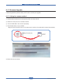
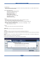
4.1.7.1. Using the common method
① Download the firmware file in the temporary folder. And unzip the file.
② Delete all current jobs from Job Status window
③ Connect USB cable in the machine (idle state)
④ Send firmware file( *.hd ) by usblist2
-D
rag the f/w file and Drop down on the usbprn2.exe. And then f/w update will be started automatically.
Drag and Drop
⑤ Please wait until end reboot.
Service Manual
4-34
Samsung Electronics
Alignment & Troubleshooting
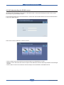
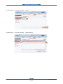
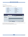
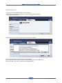
4.1.7.2. F/W upgrade using SWAS (SyncThru Web Admin Service)
- Start the SWAS program.
(Windows Start menu > Programs > Samsung Netowork Printer Utilities > SyncThru Web Admin Service)
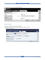
① Firmware Upgrade → Upgrade (check device using IP address)
1
1
1
2
2
2
3
3
3
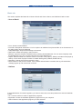
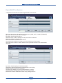
② Maintenance → Firmware upload (register firmware)
1
1
1
2
2
2
3
3
3
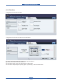
③ Maintenance → Firmware Upload (upload firmware)
1
1
1
2
2
2
3
3
3
4
4
4
Service Manual
4-35
Samsung Electronics
Alignment & Troubleshooting
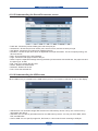
④ Maintenance → Firmware Upload (confirm uploaded firmware)
1
1
1
2
2
3
3
2
3
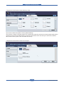
⑤ Maintenance → Firmware Upgrade → Upgrade (choose firmware)
1
1
1
2
2
3
3
2
3
⑥ Maintenance → Firmware Upgrade → Upgrade (choose firmware)
1
1
2
2
1
2
3
3
3
Service Manual
4-36
Samsung Electronics
Alignment & Troubleshooting
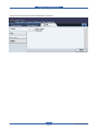
⑦ Maintenance → Firmware Upgrade → Upgrade
1
1
2
2
3
3
4
4
⑧ Maintenance → Firmware Upgrade → Upgrade (Done)
1
1
2
2
Service Manual
3
3
4-37
Samsung Electronics
Alignment & Troubleshooting
4.1.8 Diagnostics
4.1.8.1 Introduction
This document will capture the behavior specifications for the GUI Windows for Diagnostics. Each section of
this document describes one feature with a step window image and script.
However, used window image is not fixed image from the specification point of view. Acquire detail
information from script. Window image is just example image will be implemented.
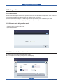
4.1.8.2 How to enter diagnostics mode
1. Press 3*4 key(1, 2, 3) simultaneously.
2. Enter password(1934).
3. Press ‘OK’ button.
4.1.8.3 How to exit diagnostics mode
By pressing the Home button, exit Diagnostics mode.
When exit Diagnostics mode, a popup window shall display.
By default, Reset Counters is No, Reboot Copier is Yes.
Service Manual
4-38
Samsung Electronics
Alignment & Troubleshooting
4.1.8.4 Diagnostics Menu Map
Information
Fault History
Fault Log
Fault Counters
General
Machine Serial number
Network IP Address
Images since last call
Service started
HFSI
Software version
Usage Counters
Test Rountines
Copier
NVM Read/Write
NVM Initialization
Engine/DADF Routines
Fax
NVM Read/Write
NVM Initialization
Fax Routines
Protocol Report
Network
NVM Initialization
Other
Print Test Pattern
Shading Test
Scan Edge Test
Memory Clear
Print Report
Reset Admin Password
Service Manual
4-39
Samsung Electronics
Alignment & Troubleshooting
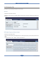
4.1.8.5 Information Tab
Information tab provides detail information of the machine.
General
• Diagnostics>Information>General
• When user selects General, OP displays Machine Serial Number, Network IP Address and Images since
last call.
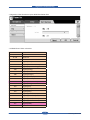
HFSI (High Frequency Service Items)
• Diagnostics>Information>HFSI
• W
hen user selects General, OP displays the list of HFSI( High Frequency Service Items) read from the
MCB.
In the list, there are “ Item”, “Status”, “Actual”, and “Max Life”.
Service Manual
4-40
Samsung Electronics
Alignment & Troubleshooting
• User Behavior
- User can select one item in the list to reset the counter using “Reset” button or to edit the Max.Life and
threshold value using “Edit” button.
• Items in this column are:
DADF Roller / Rubber Pad Life Page
T1/T2/T3 P-up Roller Life Page
Retard Roller Life Page
Bypass Rubber Pad Life page
Transfer Roller Life Page
Fuser Roller / Fuser Unit Life Page
Heat Roller Life Page
Pressure Roller Life Page
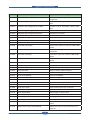
• Status
- The possible values in this column are ‘OK’, ‘Check’, ‘Negative’ and ‘Off’.
- OK : Actual counter is smaller than the threshold value
- Check : Actual counter is bigger than threshold value but smaller than Max.Life
- Off : Actual counter exceeds Max.Life
- Negative : There is no counter to display. In this case, it shall display ‘-‘ in the
Status and Max Life column.
• Actual
- Values in this column are actual counts for HFSI usage
• Max. Life
Values in this column are maximum life limits set for HFSI.
• Reset
This button is used to reset the actual counter after replacing the HFSI unit.
This button is disabled before user select one item in the list and enabled once user select any of the items
in the list.
Once user presses, a confirmation window shall display to user confirm again. The window is displayed as
below.
If user confirms reset, it will reset the counter to 0.
If the counter of selected item is 0, ‘Reset’ button shall be disabled.
Service Manual
4-41
Samsung Electronics
Alignment & Troubleshooting
• Edit
“Edit” button is disabled until user select one item in the list.
Selecting “Edit” button causes edit window to be displayed.
There are two input filed for ‘Maximum Life’ and for ‘Threshold’.
Each data field shall display default value or the last-saved value entered by the service engineer. The data
field shall support the numeric characters of 0 to 9.
The hard keypad characters of ‘#’, ‘phone’ and ‘*’ are not supported and shall generate an invalid entry
message if selected.
The hard keypad characters of ‘c’ shall delete all characters displayed within the selected data field. By
selecting ‘Cancel’, window moves back to HSFI window without saving user’s setting. By selecting ‘OK’
button, window moves back to HSFI window saving user’s setting. Threshold value shall not be greater than
Maximum Life.
Software Version
• Diagnostics>Information>Software Version
• When user selects Software version, OP displays the version of the Main Controller, Image Output Terminal,
User Interface, Network Controller, Document Feeder, Tray 2 Firmware, Tray 3 Firmware
Service Manual
4-42
Samsung Electronics
Alignment & Troubleshooting
Usage Counter
• Diagnostics>Information>Usage Counter
• When user selects Usage Counter, OP displays the amount of the Items shown below.
• Total Impressions
• Black Impressions
• Black Copied Impressions
• Black Printed Impressions
• Color Impressions
• Color Copied Impressions
• Sheets
• Copied Sheets
• Black Copied Sheets
• Color Copied Sheets
• Printed Sheets
• Black Printed Sheets
• Color Printed Sheets
• 2 Sided Sheets
• Copied 2 Sided Sheets
• Black Copied 2 Sided Sheets
Service Manual
• Color Copied 2-Sided Sheets
• Printed 2 Sided Sheets
• Black Printed 2 Sided Sheets
• Color Printed 2 Sided Sheets
• Fax Images Received
• Images Sent
• Server Fax Images Sent
• Network Scanning Images Sent
• Email Images Sent
• Maintenance Impressions
• Black Maintenance Impressions
• Known Jams in the IOT
• Known Jams in Finishing Device(s)
• Attempted Sheet Feeds from Internal trays
• Actual sheet feeds from Internal trays
• Normal Level Power On Hours
• Power Save Hours
• Attempted Original Sheet Feeds in the DADF
4-43
Samsung Electronics
Alignment & Troubleshooting
4.1.8.6 Fault History Tab
Fault History provides an error information occurred.
Fault Log
• Diagnostics>Fault History>Fault Log
• Fault log window shall display errors occurred while the product was operating.
• Diagnostics>Fault History>Fault Log>Clear
• When selecting “Clear” button, Pop-up will be displayed. If you want to delete the Fault history, touch the “OK”
button.
Service Manual
4-44
Samsung Electronics
Alignment & Troubleshooting
Fault Counters
• Diagnostics>Fault History>Fault Counters
• Fault counters window displays Fault group with number and name.
They are
• 01 Feeder
• 02 Fuser
• 03 Motor Fan
• 04 LSU
• 05 Option Interface
• 06 CRU
• 07 Finisher
• 08 DADF
• 09 FDI
• 10 Controller
• 11 Scanner
• 12 Mismatch Type
• 13 Network
• 14 Cloning
• 18 Memory State
• 21 Tray
• 24 MSOK
User shall select one item in the list at a time and multiple selection shall not supported. User can select ‘Non
Zero’ or ‘All’. By default, ‘Non Zero’ shall be selected.
When press ‘OK’, Fault Counters Detail Window shall be displayed.
Service Manual
4-45
Samsung Electronics
Alignment & Troubleshooting
Fault Counters Detail window shall display Fault code, description and value (counter) among the selected
Fault Group. Items of displayed Fault codes are different based on the selection of ‘Non Zero’ or ‘All’. When
selected ‘Non Zero’, Fault codes in the selected Fault Group having non zero counter shall be displayed.
When selected ‘All’, all Fault codes in the selected Fault Group shall be displayed. Display order of Fault
code is upward.
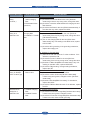
4.1.8.7 Test Routines Tab
4.1.8.7(a) Copier
NVM Read/Write
• Diagnostics>Test Routines>Copier>NVM Read/Write
“Edit” button shall be disabled until any NVM item is selected.
“Edit” button shall be disabled when read only NVM is selected. Search edit box has 00-000 as a default.
User shall input the whole number to find a specific NVM by pressing Find button. (Refer to NVM Read/Write
table) If matching NVM is found, the page including the specified NVM shall be displayed and the NVM is
shown as selected. If matching NVM is not found, error message such as “Invalid NVM number” shall be
displayed on the status area and search edit box displays default number.
Service Manual
4-46
Samsung Electronics
Alignment & Troubleshooting
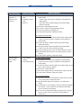
• Diagnostics>Test Routines>Copier>NVM Read/Write>Edit
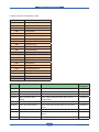
• NVRAM Read / Write code table
0~4
5
6~19
Reserved
DADF
Reserved
20
FAX
100
Engine(Motor)
101
Engine(Clutch & Actuator)
102
Engine(Paper Handling)
103
Engine(Timing)
104
Engine(Consumables)
105
Engine(Charger)
106
Engine(Developer)
107
Engine(Transfer)
108
Engine(Environment)
109
Engine(Fixing)
110
Engine(LSU)
111
Engine(Toner)
112
Engine(ACR)
113
Engine(Option/Finisher)
114
Engine(Option/SCF)
115
Engine(Option/Reserved)
116
Engine(Option/Reserved)
117
Engine(CTD)
118~255
Service Manual
Reserved
4-47
Samsung Electronics
Alignment & Troubleshooting
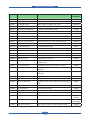
Code
NVM Description
Meaning
103-0000
Pick Up Start Time
psync ~ and pick up
103-0010
Regi Off Time
regi sensor on ~ regi clutch off
103-0021
Option Clutch On Time
Option feed sensor on ~ Option clutch on
103-0030
Delay Time of Feed Clutch On
regi clutch on ~ feed clutch on
104-0000
Pick up roller Life Page Counter
Pick up roller Life Page Counter
104-0010
Forward roller Life Page Counter
Forward roller Life Page Counter
104-0020
Retard roller Life Page Counter
Retard roller Life Page Counter
104-0030
T2 Pick-Up Roller Life Page Counter
T2 Pick-Up Roller Life Page Counter
104-0040
T3 Pick-Up Roller Life Page Counter
T3 Pick-Up Roller Life Page Counter
104-0060
Bypass Rubber Pad Life Page Counter
Bypass Rubber Pad Life Page Counter
104-0190
Transfer Roller Life Page Counter
Transfer Roller Life Page Counter
104-0210
Fuser Life Page Counter
Fuser Life Page Counter
105-0000
MHV DC Yellow
Charger HV Yellow DC Duty
105-0010
MHV DC Magenta
Charger HV Magenta DC Duty
105-0020
MHV DC Cyan
Charger HV Cyan DC Duty
105-0030
MHV DC Black
Charger HV Black DC Duty
105-0040
MHV DC Low Yellow
Charger HV Yellow Low DC Duty
105-0050
MHV DC Low Magenta
Charger HV Magenta Low DC Duty
105-0060
MHV DC Low Cyan
Charger HV Cyan Low DC Duty
105-0070
MHV DC Low Black
Charger HV Black Low DC Duty
105-0080
MHV VPP Yellow
Charger HV Yellow VPP Duty
105-0090
MHV VPP Magenta
Charger HV Magenta VPP Duty
105-0100
MHV VPP Cyan
Charger HV Cyan VPP Duty
105-0110
MHV VPP Black
Charger HV Black VPP Duty
105-0120
MHV AC Yellow
Charger HV Yellow AC Duty
105-0130
MHV AC Magenta
Charger HV Magenta AC Duty
105-0140
MHV AC Cyan
Charger HV Cyan AC Duty
105-0150
MHV AC Black
Charger HV Black AC Duty
106-0000
Deve DC Yellow
Deve DC Yellow
106-0010
Deve DC Magenta
Deve DC Magenta
106-0020
Deve DC Cyan
Deve DC Cyan
106-0030
Deve DC Black
Deve DC Black
107-0000
Transfer1 High Voltage(THV) Yellow
Transfer1 HV Yellow Duty
107-0010
Transfer1 High Voltage(THV) Magenta
Transfer1 HV Magenta Duty
107-0020
Transfer1 High Voltage(THV) Cyan
Transfer1 HV Cyan Duty
107-0030
Transfer1 High Voltage(THV) Black
Transfer1 HV Black Duty
107-0040
Transfer1 High Voltage(THV) Low Yellow
Transfer1 Low HV Yellow Duty In None Image
Area
Service Manual
4-48
Samsung Electronics
Alignment & Troubleshooting
Code
NVM Description
Meaning
107-0050
Transfer1 High Voltage(THV) Low Magenta
Transfer1 Low HV Magenta Duty In None
Image Area
107-0060
Transfer1 High Voltage(THV) Low Cyan
Transfer1 Low HV Cyan Duty In None Image
Area
107-0070
Transfer1 High Voltage(THV) Low Black
Transfer1 Low HV Black Duty In None Image
Area
107-0080
Transfer2 High Voltage(THV2)
Transfer2 HV
107-0090
Transfer2 High Voltage(THV2) Duplex
Transfer2 HV of Duplex
107-0100
PreTransfer1 Duty
PreTransfer1 Duty
107-0110
PreTransfer2 Duty
PreTransfer2 Duty
107-0120
Saw Plate Duty
Saw Plate Duty
109-0000
Fuser Bias Duty
Fuser Bias Duty
110-0000
LD Power Yellow(Half)
Yellow Laser Light Level, Value in PWM at Half
Speed
110-0010
LD Power Magenta(Half)
Magenta Laser Light Level, Value in PWM at
Half Speed
110-0020
LD Power Cyan(Half)
Cyan Laser Light Level, Value in PWM at Half
Speed
110-0030
LD Power Black(Half)
Black Laser Light Level, Value in PWM at Half
Speed
110-0040
LD Power Yellow
Yellow LD Power at Normal Speed
110-0050
LD Power Magenta
Magenta LD Power at Normal Speed
110-0060
LD Power Cyan
Cyan LD Power at Normal Speed
110-0070
LD Power Black
Black LD Power at Normal Speed
111-0000
Toner Vcon Yellow
Toner Vcon Yellow
111-0010
Toner Vcon Magenta
Toner Vcon Magenta
111-0020
Toner Vcon Cyan
Toner Vcon Cyan
111-0030
Toner Vcon Black
Toner Vcon Black
111-0060
Toner THV1 Yellow
Upper control limit of yellow TC sensor
111-0070
Toner THV1 Magenta
Upper control limit of magenta TC sensor
111-0080
Toner THV1 Cyan
Upper control limit of cyan TC sensor
111-0090
Toner THV1 Black
Upper control limit of black TC sensor
111-0140
Toner Target Yellow
Yellow target TC sensor value
111-0150
Toner Target Magenta
Magenta target TC sensor value
111-0160
Toner Target Cyan
Cyan target TC sensor value
111-0170
Toner Target Black
Black target TC sensor value
112-0120
Manual Color Regi X-offset Yellow
Distant from hsync to lsync (multi-hsync) for
yellow
112-0130
Manual Color Regi X-offset Magenta
Distant from hsync to lsync (multi-hsync) for
Magenta
Service Manual
4-49
Samsung Electronics
Alignment & Troubleshooting
Code
NVM Description
112-0140
Manual Color Regi X-offset Cyan
Distant from hsync to lsync (multi-hsync) for
Cyan
112-0150
Manual Color Regi X-offset Black
Distant from hsync to lsync (multi-hsync) for
Black
112-0160
Manual Color Regi Y-offset Yellow
Distant from psync to Image area for yellow
112-0170
Manual Color Regi Y-offset Magenta
Distant from psync to Image area for Magenta
112-0180
Manual Color Regi Y-offset Cyan
Distant from psync to Image area for Cyan
112-0190
Manual Color Regi Y-offset Black
Distant from psync to Image area for Black
112-0200
Manual Color Regi Width Yellow
Image Area Width for Yellow
112-0210
Manual Color Regi Width Magenta
Image Area Width for Magenta
112-0220
Manual Color Regi Width Cyan
Image Area Width for Cyan
112-0230
Manual Color Regi Width Black
Image Area Width for Black
117-0000
Total Condition On/Off for CTD
All Condition of CTD On/Off
117-0010
New Crum Condition On/Off for CTD
The Condition for New Crum of CTD On/Off
117-0020
Page Count Condition On/Off for CTD
The Condition for Page Count of CTD On/Off
117-0030
Page Count for CTD (Full)
Page Count for CTD (Full)
117-0040
Page Count for CTD (Short)
Page Count for CTD (Short)
117-0050
Minimum Compensation OD
Minimum Compensation OD
117-0060
Maximum Compensation OD
Maximum Compensation OD
117-0070
R_TRC Yellow
Reference TRC Value for Yellow
117-0080
R_TRC Magenta
Reference TRC Value for Magenta
117-0090
R_TRC Cyan
Reference TRC Value for Cyan
117-0100
R_TRC Black
Reference TRC Value for Black
117-0110
M_TRC Yellow
Measured TRC Value for Yellow
117-0120
M_TRC Magenta
Measured TRC Value for Magenta
117-0130
M_TRC Cyan
Measured TRC Value for Cyan
117-0140
M_TRC Black
Measured TRC Value for Black
Service Manual
Meaning
4-50
Samsung Electronics
Alignment & Troubleshooting
NVM Initialization
• Diagnostics>Test Routines>Copier>NVM Initialization
• By default, none of items is selected and Initialize button shall be disabled.
There shall be Back button.
• Diagnostics>Test Routines>Copier>NVM Initialization>Initialize
If you want to initialize the NVM values, press OK button.
When press OK button, SR shall show the initialization progress status and result.
When the result is get, pop up window shall be disappeared.
Service Manual
4-51
Samsung Electronics
Alignment & Troubleshooting
Engine/DADF Test Routines
• Diagnostics>Test Routines>Copier>Engine/DADF Test Routines.
When exit this window, OP shall send exit command. (CMD_COPY_COMP_EXITMODE)
By default, all Test routines will be displayed.
By default, search edit box has 00 .
OK/Reset button shall be disabled until any test routine is selected.
Maximum number of selection is 3.
Reset will deselect all selected test routines.
User select test routine by touching the row and deselect touching it again.
User input chain number in search edit box and only all test routines in the chain shall be
displayed.
By default, Start/Stop/Stop All shall be disabled.
Start button shall be enabled when selected item is not running.
Multiple selection shall not be supported.
Stop shall be enabled only when the selected item is running.
Stop All shall be enabled when there is any running test item.
Back button shall be disable when there is any running test item.
Service Manual
4-52
Samsung Electronics
Alignment & Troubleshooting
• Engine Diagnostic Contol(EDC) Menu
0~4
Reserved
5
DADF
6~19
Reserved
20
FAX
100
Engine(Motor)
101
Engine(Clutch & Actuator)
102
Engine(Paper Handling)
103
Engine(Timing)
104
Engine(Consumables)
105
Engine(Charger)
106
Engine(Developer)
107
Engine(Transfer)
108
Engine(Environment)
109
Engine(Fixing)
110
Engine(LSU)
111
Engine(Toner)
112
Engine(ACR)
113
Engine(Option/Finisher)
114
Engine(Option/SCF)
115
Engine(Option/Reserved)
116
Engine(Option/Reserved)
117
Engine(CTD)
118~255
Code
Reserved
Displayed Name
Meaning
100-0000
Main BLDC Motor
Main BLDC Motor is On/Off
100-0001
Main BLDC Motor Ready
Detect if Main BLDC Motor runs at normal speed
100-0002
Black OPC/DEV Motor
Black OPC/DEV BLDC Motor is On/Off
100-0003
Black OPC/DEV Motor
Ready
Detect if Black OPC/DEV BLDC Motor runs at
normal speed
100-0004
Color OPC Motor
Color OPC BLDC Motor is On/Off
100-0005
Color OPC Motor Ready
Detect if Color DEV BLDC Motor runs at normal
speed
100-0006
Color DEV Motor
Color DEV BLDC Motor is On/Off
100-0007
Color DEV Motor Ready
Detect if Color DEV BLDC Motor runs at normal
speed
100-0008
T1 Engage Motor
T1 Engage Motor On/Off
Service Manual
4-53
State
Displayed
On[Off]
High[Low]
On[Off]
High[Low]
On[Off]
High[Low]
On[Off]
High[Low]
On[Off]
Samsung Electronics
Alignment & Troubleshooting
Code
Displayed Name
Meaning
State
Displayed
100-0009
T1 Engae Sensor
Detect if the T1 Engage is On or Off.
100-0010
T2 Engage Motor
T2 Engage Motor On/Off
100-0011
T2 Engae Sensor
Detect if the T1 Engage is On or Off.
100-0012
Exit Motor Forward Fast
Exit Motor Forward Fast On/Off
On[Off]
100-0013
Exit Motor Forward Slow
Exit Motor Forward Slow On/Off
On[Off]
100-0014
Duplex Motor Forward
Duplex Motor Forward On/Off
On[Off]
100-0015
Duplex Motor Backward
Duplex Motor Backward On/Off
On[Off]
100-0016
Duplex Fan1 Run
Start/Stop Duplex Fan1 run
On[Off]
100-0017
Duplex Fan2 Run
Start/Stop Duplex Fan2 run
On[Off]
100-0018
Dupelx Fan1 Run Ready
Detects if Duplex Fan1 runs at normal speed.
High[Low]
100-0019
Dupelx Fan2 Run Ready
Detects if Duplex Fan2 runs at normal speed.
High[Low]
100-0020
T1 Elevating Motor
T1 Elevate Motor On/Off
On[Off]
100-0021
T2 Elevating Motor
T2 Elevate Motor On/Off (Optional)
On[Off]
100-0022
T3 Elevating Motor
T3 Elevate Motor On/Off (Optional)
On[Off]
100-0024
Waste Toner Motor
Waste Toner Motor On/Off
On[Off]
100-0025
Waste Toner Full Sensor
Detect if the waste toner is full or not.
100-0026
SMPS Fan Run
Start/Stop Deve. Fan run
On[Off]
101-0000
Bypass Feed Clutch
Engages drive to pick up a paper from bypass
Tray(MP Tray).
On[Off]
101-0001
T1 Pick-Up Clutch
Engages drive to pick up a paper from tray1.
On[Off]
101-0002
T2 Pick-Up Clutch
Engages drive to pick up a paper from tray2.
(Optional)
On[Off]
101-0003
T3 Pick-Up Clutch
Engages drive to pick up a paper from tray3.
(Optional)
On[Off]
101-0005
Registration Clutch
Engages drive to registartion rolls.
On[Off]
101-0006
Duplex Feed Clutch
Engages drive to feed a paper into duplex path.
On[Off]
101-0007
Duplex Gate Clutch
Engages drive to convert paper direction into duplex
path.
On[Off]
101-0008
T1 Feed Clutch
T1 Feed Clutch On/Off
On[Off]
101-0009
T2 Feed Clutch
T2 Feed Clutch On/Off
On[Off]
101-0010
T3 Feed Clutch
T3 Feed Clutch On/Off
On[Off]
101-0012
SMPS Fan Run Ready
Detects if Deve Fan runs at normal speed.
High[Low]
101-0013
Side Cover Interlock
Detect if the side cover is opened or closed.
Opened/
Closed
101-0014
Exit Cover Present Sensor
Detect when exit cover is in place.
101-0015
Out-Bin Full Sensor
Detect when a paper is at Duplex Ready sensor.
Service Manual
4-54
High[Low]
On[Off]
High[Low]
High[Low]
Install
[Not Install]
High[low]
Samsung Electronics
Alignment & Troubleshooting
Code
Displayed Name
Meaning
State
Displayed
102-0000
Tray1 Home Position
Detect when tray1 is closed.
Closed
[Opened]
102-0001
T1 Paper Empty Sensor
Detect when paper is in Tray1.
High[low]
102-0002
T1 Size1 sensor
Detects whether auto size1 sensor of tray1 is high
or low.
High[low]
102-0003
T1 Size2 sensor
Detects whether auto size2 sensor of tray1 is high
or low.
High[low]
102-0004
T1 Size3 sensor
Detects whether auto size3 sensor of tray1 is high
or low.
High[low]
102-0005
T1 Stack Height Sensor
Detects if paper in tray1 is elevated to the sensor.
High[low]
102-0006
T1 Paper Low Sensor
Detects when the stack height of tray1 is less than
25%.
High[low]
102-0007
Tray2 Home Position
Detect when tray2 is closed.
Closed
[Opened]
102-0008
T2 Paper Empty Sensor
Detect when paper is in tray2.
High[low]
102-0009
T2 Size1 sensor
Detects whether auto size1 sensor of tray2 is high
or low.
High[low]
102-0010
T2 Size2 sensor
Detects whether auto size2 sensor of tray2 is high
or low.
High[low]
102-0011
T2 Size3 sensor
Detects whether auto size3 sensor of tray2 is high
or low.
High[low]
102-0012
T2 Stack Height Sensor
Detects if paper in tray2 is elevated to the sensor.
High[low]
102-0013
T2 Paper Low Sensor
Detects when the stack height of tray2 is less than
25%.
High[low]
102-0014
Tray3 Home Position
Detect when tray3 is closed.
Closed
[Opened]
102-0015
T3 Paper Empty Sensor
Detect when paper is in tray3.
High[low]
102-0016
T3 Size1 sensor
Detects whether auto size1 sensor of tray3 is high
or low.
High[low]
102-0017
T3 Size2 sensor
Detects whether auto size2 sensor of tray3 is high
or low.
High[low]
102-0018
T3 Size3 sensor
Detects whether auto size3 sensor of tray3 is high
or low.
High[low]
102-0019
T3 Stack Height Sensor
Detects if paper in tray3 is elevated to the sensor.
High[low]
102-0020
T3 Paper Low Sensor
Detects when the stack height of tray3 is less than
25%.
High[low]
102-0028
Bypass Paper Empty Sensor Detects when paper is in Bypass Tray(MP Tray).
High[low]
102-0029
Feed Sensor
High[low]
Service Manual
Detect when a paper is at Feed sensor.
4-55
Samsung Electronics
Alignment & Troubleshooting
Code
Displayed Name
Meaning
State
Displayed
102-0030
T2 Feed Sensor (or Door
Open)
Detect when a paper is at T2 Feed sensor. (optional)
High[low]
102-0031
T3 Feed Sensor (or Door
Open)
Detect when a paper is at T3 Feed sensor. (optional)
High[low]
102-0033
Regi. Sensor
Detect when a paper is at Regi. sensor.
High[low]
102-0034
Exit Sensor
Detect when a paper is at Exit. sensor.
High[low]
102-0035
Duplex Jam1 Sensor
Detect when a paper is at Duplex Jam1 sensor.
High[low]
102-0036
Duplex Jam2 Sensor
Detect when a paper is at Duplex Jam2 sensor.
High[low]
105-0000
Yellow MHV Bias
Yellow MHV bias voltage on at normal drive level
On[Off]
105-0001
Magenta MHV Bias
Magenta MHV bias voltage on at normal drive level
On[Off]
105-0002
Cyan MHV Bias
Cyan MHV bias voltage on at normal drive level
On[Off]
105-0003
Black MHV Bias
Black MHV bias voltage on at normal drive level
On[Off]
105-0004
Yellow MHV Bias Read
Yellow Detect what the MHV value is on the MHV
Roller
On[Off]
105-0005
Magenta MHV Bias Read
Magenta Detect what the MHV value is on the MHV
Roller
On[Off]
105-0006
Cyan MHV Bias Read
Cyan Detect what the MHV value is on the MHV
Roller
On[Off]
105-0007
Black MHV Bias Read
Black Detect what the MHV value is on the MHV
Roller
On[Off]
106-0000
Yellow Dev Bias
Yellow Dev bias voltage on at normal drive level
On[Off]
106-0001
Magenta Dev Bias
Magenta Dev bias voltage on at normal drive level
On[Off]
106-0002
Cyan Dev Bias
Cyan Dev bias voltage on at normal drive level
On[Off]
106-0003
Black Dev Bias
Black Dev bias voltage on at normal drive level
On[Off]
107-0000
Yellow THV Bias Read
Detect what the THV value is on the THV Roller
Numeric 3
digits
107-0001
Magenta THV Bias Read
Detect what the THV value is on the THV Roller
Numeric 3
digits
107-0002
Cyan THV Bias Read
Detect what the THV value is on the THV Roller
Numeric 3
digits
107-0003
Black THV Bias Read
Detect what the THV value is on the THV Roller
Numeric 3
digits
107-0004
iTHV(+) Bias
iTHV plus bias voltage on at normal drive level
On[Off]
107-0005
iTHV Bias Read
Detect what the THV value is on the iTHV Roller
107-0006
iTHV(-) Bias
iTHV minus bias voltage on at normal drive level
109-0000
Fuser Temperature A
Detects what the temperature A is on fuser.
Numeric 3
digits
109-0001
Fuser Temperature B
Detects what the temperature B is on fuser.
Numeric 3
digits
Service Manual
4-56
On[Off]
Samsung Electronics
Alignment & Troubleshooting
Code
Displayed Name
Meaning
State
Displayed
109-0002
Fuser Fan Run Ready
Detects if Fuser Fan Motor runs at normal speed.
109-0003
Fuser Motor Forward
Fuser Motor Forward On/Off
On[Off]
109-0004
Fuser Fan Run
Fuser Fan Motor On/Off
On[Off]
109-0005
Fuser Bias
Fuser bias voltage on at normal drive level
On[Off]
109-0006
Heater Over Heat Sensor
Detect if the Heater is in Overheat Status.
High[Low]
109-0007
Heater Low Heat Sensor
Detect if the Heater is in Lowheat Status.
High[Low]
109-0008
Heater Open Heat Sensor
Detect if the Heater is in Openheat Status.
High[Low]
110-0000
LSU Motor1 Run Ready
Detects if LSU motor1 runs at normal speed.
High[Low]
110-0001
LSU Motor2 Run Ready
Detects if LSU motor2 runs at normal speed.
High[Low]
110-0002
LSU Fan1 Run Ready
Detects if LSU Fan Motor runs at normal speed.
High[Low]
110-0003
LSU Fan2 Run Ready
Detects if LSU Sub Fan Motor runs at normal speed.
High[Low]
110-0004
LSU Clean Motor
Detect if the LSU Clean Motor On/Off
High[Low]
110-0005
LSU Clean Sensor
Detect if the LSU Clean Motor is On or Off
High[Low]
110-0006
LSU Motor1 Run
LSU Motor1 On/Off
On[Off]
110-0007
LSU Motor2 Run
LSU Motor2 On/Off
On[Off]
110-0008
LSU LD Power1
LSU LD1 Power On/Off (yellow)
On[Off]
110-0009
LSU LD Power2
LSU LD2 Power On/Off (magenta)
On[Off]
110-0010
LSU LD Power3
LSU LD3 Power On/Off (cyan)
On[Off]
110-0011
LSU LD Power4
LSU LD4 Power On/Off (black)
On[Off]
110-0012
LSU Fan1 Run
Start/Stop LSU Fan Run
On[Off]
110-0013
LSU Fan2 Run
Start/Stop LSU Sub Fan Run
On[Off]
111-0000
Toner Dispense Motor
Yellow
Toner Dispense(Supply) Motor On/Off
On[Off]
111-0001
Toner Dispense Motor
Magenta
Toner Dispense(Supply) Motor On/Off
On[Off]
111-0002
Toner Dispense Motor Cyan
Toner Dispense(Supply) Motor On/Off
On[Off]
111-0003
Toner Dispense Motor Black Toner Dispense(Supply) Motor On/Off
On[Off]
111-0004
Toner Sensor Yellow
TC sensor in developer tank.
x.xx voltage
111-0005
Toner Sensor Magenta
TC sensor in developer tank.
x.xx voltage
111-0006
Toner Sensor Cyan
TC sensor in developer tank.
x.xx voltage
111-0007
Toner Sensor Black
TC sensor in developer tank.
x.xx voltage
112-0000
ACR Execute Now
Start Auto Color Registration
113-0000
Finisher Present Sensor
Detect if the Finisher is in place.
113-0001
Entrance Motor
Entrance Motor run as IOT Speed <about 5 sec>
On[Off]
113-0002
Exit Motor
Exit Motor run as IOT Speed <about 5 sec>
On[Off]
113-0003
Paddle Motor
Paddling
Service Manual
High[Low]
Install
[Not Install]
On
4-57
Samsung Electronics
Alignment & Troubleshooting
Code
Displayed Name
Meaning
State
Displayed
113-0004
Front Jog Home
Front Jogger move Home
On
113-0005
Front Jog Stand
Front Jogger move to Stand
On
113-0006
Rear Jog Home
Rear Jogger move Home
On
113-0007
Rear Jog Stand
Rear Jogger move to Stand
On
113-0008
Support Finger Home
Supporter move Home
On
113-0009
Support Finger Stand
Supporter move to Stand
On
113-0010
Ejector Motor
Ejecting
On
113-0011
Stacker Down
Stacker down to bottom
On
113-0012
Stacker Up
Stacker up to Stacking position
On
113-0013
Stapler
Staple when no cartridge
On
113-0014
Entrance Sensor
Detect paper at paper feeding area.
High[Low]
113-0015
Exit Sensor
Detect paper at paper exit area.
High[Low]
113-0016
Paddle Home Sensor
Detect Paddle Home position
High[Low]
113-0017
Front Jog Home Sensor
Detect Front Jog Home position
High[Low]
113-0018
Rear Jog Home Sensor
Detect Rear Jog Home position
High[Low]
113-0019
Support Finger Home
Sensor
Detect Support-Finger Home position
High[Low]
113-0020
Ejector Home Sensor
Detect Ejector Home position
High[Low]
113-0021
Ejector Encoder Sensor
Detect Ejector Encoder sensor
High[Low]
113-0022
Stacker Top Sensor
Detect Stacker Top position
High[Low]
113-0023
Stacker Bottom Switch
Detect Staple Bottom position
High[Low]
113-0024
Staple Home Sensor
Detect Staple Home position
High[Low]
113-0025
Staple Ready Sensor
Detect Staple Ready to clinching.
High[Low]
113-0026
Low Staple Sensor
Detect Staple Low
High[Low]
113-0027
Paper Detector Sensor
Detect paper in stapler area
High[Low]
113-0028
Finisher Door Switch
Detect Finsher Door Open or Close
High[Low]
113-0029
IOT Set Sensor
Detect Finisher is connected with IOT.
High[Low]
113-0030
Duplex Paper Sensor
Deetct Duplex Paper feeding from IOT.
High[Low]
117-0000
CTD Execute Now
Start CTD
117-0001
Print CTD Check Page
Print CTD Check Page
Service Manual
4-58
Samsung Electronics
Alignment & Troubleshooting
4.1.8.7(b) Fax
NVM Read/Write
• Diagnostics>Test Routines>Fax>NVM Read/Write
For the behavior, refer to Copier-NVM Read/Write.
Service Manual
4-59
Samsung Electronics
Alignment & Troubleshooting
For the behavior, refer to Copier-NVM Read/Write-Edit.
NVM Initialization
• Diagnostics>Test Routines>Fax>NVM Initialization
• By default, none of items is selected and Initialize button shall be disabled.
There shall be Back button.
Service Manual
4-60
Samsung Electronics
Alignment & Troubleshooting
• Diagnostics>Test Routines>Fax>NVM Initialization>Initialize
If you want to initialize the NVM values, press OK button.
When press OK button, SR shall show the initialization progress status and result.
When the result is get, pop up window shall be disappeared.
Protocol Report
• Diagnostics>Test Routines>Fax>Protocol Report
• When selecting Protocol Report, the sub-item will be displayed. By pressing the print, you can print the
protocol report.
Service Manual
4-61
Samsung Electronics
Alignment & Troubleshooting
Fax Routines
• Diagnostics>Test Routines>Fax> Fax Routines
• For the behavior, refer to Engine/DADF Test Routines
4.1.8.7(c) Network
NVM Initialization
• Diagnostics>Test Routines>Network>NVM Initialization
Service Manual
4-62
Samsung Electronics
Alignment & Troubleshooting
• Diagnostics>Test Routines>Network>NVM Initialization>Initialize
If you want to initialize the NVM values, press OK button.
When press OK button, SR shall show the initialization progress status and result.
When the result is get, pop up window shall be disappeared.
Service Manual
4-63
Samsung Electronics
Alignment & Troubleshooting
4.1.8.7(d) Other
• Diagnostics>Test Routines>Other
• Diagnostics>Test Routines>Other>Print Test Pattern
You can print the test pattern by pressing the start test button.
By default, Test Pattern number shall be 1.
You can select paper source by selecting tray of the image.
You can select simplex/duplex printing option by selecting 1 sided /2 sided button.
Service Manual
4-64
Samsung Electronics
Alignment & Troubleshooting
• Diagnostics>Test Routines>Other>Shading Test
The function is used to set the optimum scan quality determined by the specific characteristics of the CCD
(Charge Coupled Device). If copy image quality is poor perform this function to check the condition of the
CCD unit.
• Diagnostics>Test Routines>Other>Scan Edge Test
Service Manual
4-65
Samsung Electronics
Alignment & Troubleshooting
• Diagnostics>Test Routines>Other>Memory Clear
The function resets the system to factory default settings.
This function is used to reset the system to the initial value when the product is functioning abnormally. All the
values are returned to the default values, and all the information which was set by the user will be erased.
When select memory clear, user can select the country.
• Diagnostics>Test Routines>Other>Print Report
Service Manual
4-66
Samsung Electronics
Alignment & Troubleshooting
• Diagnostics>Test Routines>Other>Reset Admin. password
Service Manual
4-67
Samsung Electronics
Alignment & Troubleshooting
4.2 Troubleshooting
4.2.1 Procedure of Checking the Symptoms
Before attempting to repair the printer first obtain a detailed description of the problem from the customer.
Power On
OP Panel
ON?
- No Power
- Power Module error
- Main PBA error
- LCD Panel error
Ready or
Power save
Indicate
Error Massage
Refer to
Error Massage
< Chapter 4.2.2 >
Test Print
printing
Quality is
Nomal?
Refer to "Solution
of 4.2.6 Print Quality"
END
Service Manual
4-68
Samsung Electronics
Alignment & Troubleshooting
4.2.2 Display Meassage Troubleshooting
Messages appear on the Smart Panel program window or on the control panel display to indicate machine
status or errors. Refer to the tables
below to understand the messages meaning to correct the problem, if necessary.
Message
Meaning
Suggested Solutions
{Color} toner is low. Order
new toner cartridge
Toner Cartridge is almost empty.
{Color} imaging unit is not
compatible. Check user's
guide
The imaging unit you have installed Install a Samsung gunuine toner cartridge,
is not for your machine.
designed for your machine.
{Color} imaging unit is not
installed. Install it
The imaging unit is not tinstalled,
or the CRUM in the cartridge is not
connected.
Check the connection between imaging unit
CRUM connnector and SET.
{Color} imaging unit is
worn. Replace with new
one
The imaging unit is at the end of its
life.
Install a new Imaging unit.
{Color} toner cartridge is
not compatible. Check
user's guide
The toner cartridge you have
installed is not for your machine.
Install a new toner cartridge.
{Color} toner cartridge is
not installed. Install it
The toner cartridge is not installed
or the CRUM in the cartridege is
not properly connected.
Check the connection between toner cartridge
CRUM connnector and SET.
{Color} toner cartridge is
worn. Replace with new
one
The color toner cartridge has run
out. The machine stops printing.
Install a new toner cartridge.
{Color} toner cartridge is
worn. Replace with new
one
The toner cartridge has run out.
The machine stops printing.
Replace a new toner cartridge.
{Color} toner is empty.
Replace toner cartridge
The lifespan of the color toner
cartridge which the arrow indicates
is reached.
Install a new toner cartridge.
{Side/Main} Door is open.
Close it
The side door or main door is open. 1. Open and close the door. If the message is
not disappeared, check the below steps.
2. Check that the door switch is pushed.
3. Check that the Ui message is chaged by
door switch action.
4. Check the door switch signal on EDC
mode.
Communication problem
occurred with tray2
or
Communication problem
occurred with tray2(HCF)
Tray2 or HCF is not installed.
Service Manual
4-69
Install a new toner cartridge.
Check the connection between Tray2 and
HCF. If there is any problem, replace the
tray2 and HCF board. If the problem persists,
replace the main board.
Samsung Electronics
Alignment & Troubleshooting
Message
Meaning
Suggested Solutions
Communication error with Network
board
Check the Network board connection. If there
is any problem, replace the Network board. If
the problem persists, replace the main board.
Communication problem
Communication error with scanner
occurred with scanner unit unit
Check the Scanner connection. If there is any
problem, replace the Scanner board. If the
problem persists, replace the main board.
DC motor does not
operate: #03-010. Please
turn off then on
DC motor for transfer belt does not
operate.
Replace the Engage motor or Engage check
sensor for transfer belt.
DC motor does not
operate: #03-011. Please
turn off then on
DC motor for transfer roller does
not operate.
Replace the Engage motor or Engage check
sensor for transfer roller.
Did not supply enough
{Color} toner. Remove
seal tape & reinstall
Did not supply enough {black}
toner.
Remove the seal tape of the imaging unit.
Did not supply enough
{Color} toner. Please
open/close door
Not supplied toner to the imaging
unit.
1. Check the Toner supply Motor is driving
2. Check the toner supply shutter is working
out properly.
3. Check the toner supply entrance is closed.
4. Check the Toner supply pipe is closed.
5. Check the T/C sensor
6. Check TC sensor ADC of the Engine B/D
Exit door of scanner is
open
DADA exit door is open
1. Close the DADF exit door.
Fan does not operate:
#03-002~5. Please turn
off then on
Fan does not operate.
Find out the defective FAN. Replace it.
Fax unit error: #10-002.
Please turn off then on
1. Fax card is not installed.
1. Replace the Fax unit.
2. Fax card is not installed properly. 2. If the problem persists after replacing the
3. Fax card is out of order.
Fax unit, replace the Fax unit.
4. In case that you didn't modem
install after installing fax card
Finisher door is open.
Close it
Finisher door is open.
Close the finisher door.
Finisher error: #07007~014. Please turn off
then on
There is a problem in the finisher
unit.
Turn the machine off and reinstall the finisher
again. Check that the finisher cable is
connected properly.
Communication problem
occurred with network
board
Service Manual
4-70
Samsung Electronics
Alignment & Troubleshooting
Message
Meaning
Suggested Solutions
Fuser error: #02-001.
Please turn off then on
1. At warm up, the temperature
keep up the lower temperature
for regular time.
2. In case that the temperature
has not reached warm up
temperature after warm-up time.
3. At ready, Less than target
temperature and for more than
10 sec.
4. At printing, Less than printing
Ref. temp and for more than 10
sec.
1. Check the Thermostat. If it is defective,
replace it.
2. Check the Lamp. If it is defective, replace it.
3. Check the fuser connector. Reconnect it.
4. If the Heat On signal is not occurred from
Power supply, replace it.
Fuser error: #02-002.
Please turn off then on
1. At warm up, the temperature
Replace the Fuser/Fuser control board/Engine
keep up the lower temperature
controller
for regular time.
2. At warm up, after temperature
checking time, more than regular
temperature and for more 10 sec.
3. At standby or sleep, more than
Top temp and for a few minutes.
4. At power save mode, the
temperature keep up the
constant for regular time.
Hard disk drive error: #10- 1. Hard disk is not installed
003. Please turn Off then 2. Hard disk is out of order.
On
1. Turn off the power. And reconnect the
connector of the Hard disk.
2. If the error message is still displayed,
replace the Hard disk.
3. If the problem persists, replace the main
board.
Imaging unit error: #06013~16. Please turn off
then on
Imaging unit error
1. Check the T/C sensor Harness connection.
2. Check the output wave form of the T/C
sensor.
3. Check the Engine B/D TC Sensor ADC
LSU error: #04-000.
Please turn off then on
LSU motor does not operate.
Check the LSU motor noise. If there is any
dirving noise, check the motor signal.
LSU error: #04-001.
Please turn off then on
After LD on, the Laser beam detect
signal is not occurred or irregular.
1. Check the Beam Detecht signal. If there is
a BD signal, replace the Main board. If or
not, check the LD contol signal.
2. Check the LD Power is normal.
3. If it is normal, check the light receving part.
LSU error: #04-002.
Please turn off then on
LSU motor does not operate or the
drive signal is abnormal.
Check the LSU motor noise. If there is any
dirving noise, check the motor ready signal.
LSU error: #04-003.
Please turn off then on
Yellow LSU motor does not operate. Check the LSU motor noise. If there is any
dirving noise, check the motor signal.
Service Manual
4-71
Samsung Electronics
Alignment & Troubleshooting
Message
Meaning
Suggested Solutions
LSU error: #04-004.
Please turn off then on
After Yellow LD on, the Laser beam 1. Check the Beam Detecht signal. If there is
detect signal is not occurred or
a BD signal, replace the Main board. If or
irregular.
not, check the LD contol signal.
2. Check the LD Power is normal.
3. If it is normal, check the light receving part.
LSU error: #04-006.
Please turn off then on
Magenta LSU motor does not
operate.
Check the LSU motor noise. If there is any
dirving noise, check the motor signal.
LSU error: #04-007.
Please turn off then on
After Magenta LD on, the Laser
beam detect signal is not occurred
or irregular.
1. Check the Beam Detecht signal. If there is
a BD signal, replace the Main board. If or
not, check the LD contol signal.
2. Check the LD Power is normal.
3. If it is normal, check the light receving part.
LSU error: #04-009.
Please turn off then on
Cyan LSU motor does not operate.
Check the LSU motor noise. If there is any
dirving noise, check the motor signal.
LSU error: #04-010.
Please turn off then on
After Cyan LD on, the Laser beam
detect signal is not occurred or
irregular.
1. Check the Beam Detecht signal. If there is
a BD signal, replace the Main board. If or
not, check the LD contol signal.
2. Check the LD Power is normal.
3. If it is normal, check the light receving part.
Memory failure: #10-001.
Please turn off then on
At system booting, the memory is
not read.
Replace the memory.
Motor does not operate:
#03-000. Please turn off
then on
After ITB BLDC motor is operated,
the ready signal is not occurred
within 1 sec.
Check the ITB waste toner is eliminated
properly. If the ITB waste toner overflows,
the motor error will be occurred because of
increasing the torque. Replace the developing
unit.
Motor does not operate:
#03-006. Please turn off
then on
After Black OPC BLDC motor is
operated, the ready signal is not
occurred within 1 sec.
Check the ITB waste toner is eliminated
properly. If the ITB waste toner overflows,
the motor error will be occurred because of
increasing the torque. Replace the developing
unit.
Motor does not operate:
#03-007. Please turn off
then on
After Color OPC BLDC motor is
operated, the ready signal is not
occurred within 1 sec.
Check the ITB waste toner is eliminated
properly. If the ITB waste toner overflows,
the motor error will be occurred because of
increasing the torque. Replace the developing
unit.
Motor does not operate:
#03-008. Please turn off
then on
After Color Dev BLDC motor is
operated, the ready signal is not
occurred within 1 sec.
Take out and Shake the developing unit
horizontally. And reinstall it. If the problem
persists, Replace the developing unit.
Service Manual
4-72
Samsung Electronics
Alignment & Troubleshooting
Message
Meaning
Suggested Solutions
Original paper does not
feed in scanner
The lead edge of the document
failed to actuate the scan sensor
within the correct time after
actuating the registration sensor.
1. Open the DADF door. And remove the
jammed paper. Close the DADF door.
2. Open the platen door and remove the
jammed paper.
3. Open the reverse stack door and remove
the jammed paper.
4. Check the paper exit.
Original paper is too long
for scanner. Check size
Oversized document or doublefeeding of originals.
1. Check the paper exit and remove the
jammed paper.
2. Open the Platen door and remove the
jammed paper.
3. Open the ReverseStack door and remove
the jammed paper.
4. Open the DADF door and remove the
jammed paper.
Original paper jam in front Paper has jammed during duplex
of scanner duplex path
printing in the DADF.
1. Open the DADF door. And remove the
jammed paper. Close the DADF door.
2. Open the platen door and remove the
jammed paper.
3. Open the reverse stack door and remove
the jammed paper.
4. Check the paper exit.
Original paper jam in front The originals are jammed in DADF
of scanner
1. Remove the all document on DADF.
2. Remove the jammed paper in DADF.
Original paper jam inside
of scanner duplex path
1. The lead edge of the document
failed to actuate the reverse
stack sensor within the correct
time after actuating the gate
sensor.
2. The edge of the document failed
to actuate the reverse stack
sensor.
1. Open the ReverseStack door. And remove
the jammed paper.
2. Open the platen door and remove the
jammed paper.
3. Open the DADF door and remove the
jammed paper.
4. Check the paper exit.
Original paper jam inside
of scanner
The lead edge of the document
failed to actuate the gate sensor
within the correct time after
actuating the scan sensor.
When the machine is on, jammed
paper is detected in the DADF.
1. Open the DADF door. And remove the
jammed paper. Close the DADF door.
2. Open the platen door and remove the
jammed paper.
3. Open the reverse stack door and remove
the jammed paper.
4. Check the paper exit.
Service Manual
4-73
Samsung Electronics
Alignment & Troubleshooting
Message
Meaning
Suggested Solutions
Original paper jam inside
of scanner
After power on and initializing, the
original is sensed by DADF inner
sensor(Regi, Scan, Gate, Duplex,
Reverse Stack)
1. Open the DADF door. And remove the
jammed paper. Close the DADF door.
2. Open the platen door and remove the
jammed paper.
3. Open the reverse stack dooor and remove
the jammed paper.
4. Check the paper exit.
Original paper jam
while reversing paper in
scanner
The lead edge of the document
failed to actuate the duplex sensor
within the correct time when the
document was fed the wrong way.
1. Open the DADF door. And remove the
jammed paper. Close the DADF door.
2. Open the platen door and remove the
jammed paper.
3. Open the reverse stack door and remove
the jammed paper.
4. Check the paper exit.
Paper jam at exit of
finisher
Paper jammed in the stacker.
Open the stacker door and remove jammed
paper by lowering guide 1a or 1b.
Paper Jam at the bottom
of duplex path
Paper has jammed during duplex
printing.
If there is no paper but the error message
is displayed, check the Duplex sensor.
(Component Test)
Paper Jam at the top of
duplex path
Paper has jammed during duplex
printing.
If there is no paper but the error message
is displayed, check the Duplex sensor.
(Component Test)
Paper Jam in exit area
Paper has jammed in the fuser
area.
1.If there is not jammed paper but the
error is occured, Check the Exit Sensor
(Component Test -> Sensor Read -> EX
value)
Paper jam in front of
finisher
Paper jammed in the stacker.
Open the stacker door and remove jammed
paper by lowering guide 1a or 1b.
Paper Jam in MP tray
Paper misfed from multi-purpose
tray.
1. If pick up roller does not rotate , check the
pick up clutch.
2. If Pickup roller is rotating but the paper is
not feeding, replace the pick up rubber.
3. Check the feed sensor. If it is defective,
replace it.
Paper Jam in tray1
Paper has jammed in the feeding
area of the tray.
1. Open the side door and remove the jammed
paper.
2. If pick up roller does not rotate , check the
pick up clutch.
3. If Pickup roller is rotating but the paper is
not feeding, replace the pick up rubber.
4. Check the feed sensor. If it is defective,
replace it.
Service Manual
4-74
Samsung Electronics
Alignment & Troubleshooting
Message
Meaning
Suggested Solutions
Paper Jam in tray2
or
Paper Jam in tray2(HCF).
Paper has jammed in the feeding
area of the tray.
1. Open the tray2 or HCF door and remove
the jammed paper.
2. If pick up roller does not rotate , check the
pick up clutch.
3. If Pickup roller is rotating but the paper is
not feeding, replace the pick up rubber.
4. Check the feed sensor. If it is defective,
replace it.
Paper Jam in tray3
Paper has jammed in the feeding
area of the tray.
1. If there is no paper but the error message
is displayed, check the Feed sensor or
hardware.
2. If Pickup roller is rotating and the paper is
feeding, check the pick up clutch.
Paper Jam in tray3(HCF)
Paper has jammed in the feeding
area of the tray.
1. Open the tray3 door and remove the
jammed paper.
2. If pick up roller does not rotate, check the
pick up clutch.
3. If Pickup roller is rotating but the paper is
not feeding, replace the pick up rubber.
4. Check the feed sensor. If it is defective,
replace it.
Paper jam inside finisher
Paper jammed in the stacker.
Open the stacker door and remove jammed
paper by lowering guide 1a or 1b.
Paper jam inside finisher's Paper jammed in the stacker.
duplexer
Open the stacker door and remove jammed
paper by lowering guide 1a or 1b.
Paper Jam inside of
duplex path
Paper has jammed during duplex
printing.
If there is no paper but the error message
is displayed, check the Duplex sensor.
(Component Test)
Paper Jam inside of
machine
Paper has jammed in the
registration area
1. Open the Side door and remove the
jammed paper.
2. If there is not jammed paper but the error
is occured, Check the Registration Sensor
(Component Test -> Sensor Read -> RG
value)
3. If the paper stopped after actuating the Exit
sensor, Check the Exit sensor (Component
Test -> Sensor Read -> EX value)
Scanner locking switch is The CCD lock has been locked.
locked or another problem the CCD does not detect its home
occurred
location or move.
Unlock the CCD lock.
Sensor failure: #10-012.
Call for service
Check the external temperature sensor and
main board. If it is defective, replace it.
Service Manual
Sensor error.
4-75
Samsung Electronics
Alignment & Troubleshooting
Message
Meaning
Suggested Solutions
Shake {Color} toner
cartridge
The toner supply is low
Thoroughly roll the new cartridge five or six
times to distribute the toner evenly inside the
cartridge.
Staple cartridge is empty.
Replace it
Stapler is run out.
Replace the staple cartridge.
Staple cartridge is not
installed. Install it in
finisher
Staple cartridge is not installed
Install the staple cartridge.
Supplying and mixing
toner to {Color} imaging
unit... Please wait
Supplying and mixing toner to
{black} imaging unit
Wait until the message is disappeared.
System error: #02-000.
Please turn off then on
1. At warm up, the temperature is
less than reference temperature
for 20 sec.
2. Abnormal ADC has occurred.
3. ZeroCross Signal detect error
has occurred.
1. In case of meaning 1, replace the Fuser
unit.
2. In case of meaning 3, replace the Engine
contol board or Fuser control board or
SMPS.
System error: #02-003.
Please turn off then on
The communication error of the
MEGA88 Micom
Replace the Engine controller
System error: #10-004.
Please turn off then on
Communication error with UI
Check the UI connector. If there is any
problem, replace the UI board. If the problem
persists, replace the main board.
This IP address conflicts
The IP address is used in other
with an IP address already place elsewhere.
in use. Check it
Check the IP address or obtain a new IP
address.
Toner cartridge: #06-006.
Please turn off then on
Toner Cartridge Error
1. Reinstall the toner cartridge.
2. Reconnect the harness.
Toner cartridge: #06-007.
Please turn off then on
Toner Cartridge Error
1. Reinstall the toner cartridge.
2. Reconnect the harness.
Too much paper in finisher The stacker is full of printouts.
stacker. Remove printed
paper
Remove the printed paper.
Too much paper in output
bin tray. Remove printed
paper
The printed papers are full on the
output tray.
1. Remove the paper on the output tray.
2. Check the Outbin Full Senosr (Component
Test -> Sensor Read -> OB)
Top door of scanner is
open
1. DADF door is open during DADF 1. Open the DADF door. And remove the
driving.
jammed paper. Close the DADF door.
2. Platen Door is open during DADF 2. Open the platen door and remove the
driving.
jammed paper.
3. Open the reverse stack dooor and remove
the jammed paper.
4. Check the paper exit.
Service Manual
4-76
Samsung Electronics
Alignment & Troubleshooting
Message
Meaning
Suggested Solutions
Top door of scanner is
open
DADF door is open
1. Close the DADF door.
Tray2 door is open. Close
it
Tray2(HCF) door is open.
Close it
Tray2 or HCF door is open.
1. Open and close the door. If the message is
not disappeared, check the below steps.
2. Check that the door switch is pushed.
3. Check that the Ui message is chaged by
door switch action.
4. Check the door switch signal on EDC
mode.
Tray3 door is open. Close
it
Tray3 door is open.
1. Open and close the door. If the message is
not disappeared, check the below steps.
2. Check that the door switch is pushed.
3. Check that the Ui message is chaged by
door switch action.
4. Check the door switch signal on EDC
mode.
Service Manual
4-77
Samsung Electronics
Alignment & Troubleshooting
4.2.3 System Diagnostic
Problem Description
Cause Description
Action to Resolve
Low Image Density
1. Low Toner
[1. Low Toner Concentration]
for a Particular Color
Concentration
1.1) Print out CTD check page [EDC #117-0001].
2. High OPC Surface
1.2) If the output has low toner concentration, execute CTD
Potential
calibration [EDC #117-0000], and print CTD check page
3. Poor T1 Transferring
again.
1.3) If the toner concentration is still low, go to [DE-003] Failure
in CTD Calibration.
[2. High OPC Surface Potential]
2.1) Check and confirm MHV Bias for the color [TM #1050000~0016].
2.2) If there is any wrong value, change the value [TM #1050000~0016].
2.3) Turn on the Charging Bias for the color [EDC #1050000~0003]
2.4) Read the MHV value for the color [EDC #105-0004~0007]
2.5) If any mis-reading on the MHV value, replace HVPS-L PBA.
[3. Poor T1 Transferring]
3.1) Check and confirm THV1 Bias for the color [TM #1070000~0007]
3.2) If there is any wrong value, check and confirm the contact
point between the rear side of ITB and frame.
3.3) Read the THV1 value for the color [EDC #107-0000~0003]
3.4) If any mis-reading on the MHV value, replace HVPS-L PBA.
Low Image Density
for All Colors
1. Poor T2 Transfer
[1. Poor T2 Transfer]
2. Wrong CTD Sensing 1.1) C
heck and confirm THV2 Bias for the color [TM #1070008~0009]
1.2) If there is any wrong value, check and confirm the contact
point of T2 driving roller in side unit.
1.3) Read the THV2 value for the color [EDC #107-0004~0007]
1.4) If any mis-reading on the THV2 value, replace HVPS-L
PBA.
Vertical Irregular
Image Density for a
Particular Color
1. Unbalanced
Metering Blade Gap
2. Unbalanced
Developer
Distribution at
Developing Gap
Service Manual
[1. Unbalanced Metering Blade Gap]
1.1) Replace the Imaging unit.
[2. Unbalanced Developer Distribution at Developing Gap]
2.1) Replace the Imaging unit.
4-78
Samsung Electronics
Alignment & Troubleshooting
Problem Description
Cause Description
Action to Resolve
Vertical Irregular
1. Unbalanced T2
Image Density for All
Transfer
Colors
[1. Unbalanced T2 Transfer]
1.1) Check the THV value.[EDC #107-0005] If there is any
wrong value, replace the HVPS
1.2) Check the T2 Engage/Disenage Motoer[EDC #100-0010].
If it is defective, replace the T2 Engage Motor.
1.3) Check the T2 Engage/Disenage sensor [#EDC #100-0011].
If it is defective, replace the sensor.
1.4) When checking T2 Engage/Disenage [#EDC #100-0010],
check that the T2 Roller work or not. If not work, replace
the T2 Unit.
1.5) Check the ITB Drive Roller Ground. If it is defective, replace
the ITB.
Image Density
1. Unbalanced T1
Difference between
Transfer Roller Nip
Right and Left Sides
for a Particular Color
[1. Unbalanced T1 Transfer Roller Nip]
1.1) Check that the Front Cover is locking properly.
1.2) Take out the ITB and check the T1 roller state. If it is
defective, replace the ITB.
Image Density
Difference between
Right and Left Sides
for All Colors
1. Unbalanced T2
Transfer Roller Nip
[1. Unbalanced T2 Transfer Roller Nip]
1.1) Check that the Side Cover is locking properly.
1.2) Check the T2 Engage/Disenage Motoer[EDC #100-0010].
If it is defective, replace the T2 Engage Motor.
1.3) Check the T2 Engage/Disenage sensor [#EDC #100-0011].
If it is defective, replace the sensor.
1.4) When checking T2 Engage/Disenage [#EDC #100-0010],
check that the T2 Roller work or not. If not work, replace
the T2 Unit.
1.5) Check the ITB Drive Roller Ground. If it is defective, replace
the ITB.
Horizontal White
Line(s)
1. Mis-Contact on T1
and/or Charging
Bias
2. Electrostatic Noise
[1. Mis-Contact on T1 and/or Charging Bias]
1.1) Take out the ITB and check the T1 roller conditions. If it is
defective, replace the ITB.
1.2) Check and confirm MHV Bias for the color [TM #1050010~0016]. If there is any wrong value, change the value
[TM #105-0010~0016].
1.3) Turn on the Charging Bias for the color [EDC #1050000~0003]
1.4) Read the MHV value for the color [EDC #105-0004~0007]
1.5) If any mis-reading on the MHV value, replace HVPS-L PBA.
1.6) Check the OPC grounding. If the grounding is defective,
replace the Imaging unit.
1.7) Check the ITB grounding. If the grounding is defective,
replace the ITB unit.
Service Manual
4-79
Samsung Electronics
Alignment & Troubleshooting
Problem Description
Cause Description
Action to Resolve
Horizontal White
Line(s)
(continue..)
1. Mis-Contact on T1
and/or Charging
Bias
2. Electrostatic Noise
(continue..)
[2. Electrostatic Noise]
2.1) Check and confirm Dev Bias for the color [TM #1060000~003], If there is any wrong value, change the value.
2.2) Check the connection state between the Imaging unit and
Bias harness.
2.3) Check the Dev Bias for the color [EDC #106-0000~003]. If
the value has any noies, replace the HVPS
Horizontal Sharp
Line(s) for a
Particular Color
1. Mis-Contact on
[1. Mis-Contact on Charging Bias]
Charging Bias
1.1) C
heck and confirm MHV Bias for the color [TM #1052. Unstable T1 Transfer
0010~0016]. If there is any wrong value, change the value
Bias
[TM #105-0010~0016].
1.2) Turn on the Charging Bias for the color [EDC #1050000~0003] If any mis-reading on the MHV value, replace
HVPS-L PBA.
1.3) Check the OPC grounding. If the grounding is defective,
replace the Imaging unit.
[2. Unstable T1 Transfer Bias]
1.1) Take out the ITB and check the T1 roller conditions. If it is
defective, replace the ITB.
1.2) Check and confirm T1 Bias for the color[TM #1070000~0007], If there is any wrong value, change the value.
1.3) Read the T1 Bias value[EDC #107-0000~003]. If any misreading on the MHV value, replace HVPS PBA.
1.4) Check the ITB grounding. If the grounding is defective,
replace the ITB.
Horizontal Sharp
Line(s) for Multiple
Colors of 78mm gap
1. Unstable T2 Transfer [1. Unstable T2 Transfer Bias Contact]
Bias Contact
1.1) Check the connection harness of T2 Bias.
1.2) Check the confirm THV2 bias [TM #107-0008~0009].
If there is any wrong value, change the value. [TM #1070008~0009]
1.3) Read the THV2 bias[EDC #107-0005]. If it is defective,
replace the HVPS.
1.4) Check the ITB Drive Roller Ground. If it is defective, replace
the ITB.
Horizontal Thick
Band(s) for a
Particular Color
1. Unstable Charging
Bias
2. Unstable Transfer
Bias
Service Manual
[1. Unstable Charging Bias]
1.1) Check and confirm the Charge Bias [TM #105-0010~0016].
If there is any wrong value, change the value.
1.2) Check and confirm the Charge Bias [EDC #105-0000~003].
If there is a noise, check the ITB grounding.
4-80
Samsung Electronics
Alignment & Troubleshooting
Problem Description
Horizontal Thick
Band(s) for a
Particular Color
(continue..)
Cause Description
1. Unstable Charging
Bias
2. Unstable Transfer
Bias
(continue..)
Action to Resolve
1.3) If the ITB grounding is OK, check the THV bias. [TM #1070000~0009]
- If there is any wrong value, change the value [TM #1070000~0009],
- If the THV value is defective [EDC #107-0000~0005],
replace the HVPS.
1.4) Check the Transfer Bias Harness.
1.5) If it is OK, check the Charging Bias Harness.
1.6) If it is OK, replace the Imaging unit.
1.7) If the problem persists, replace the HVPS.
[2. Unstable Transfer Bias]
2.1) Check and confirm the transfer bias [TM #107-0000~0009].
If there is any wrong value, change the value [TM #1070000~0009].
2.2) If the THV value is defective [EDC #107-0000~0005],
replace the HVPS.
2.3) Check the transfer bias noise [EDC #107-0000~0005].
If there is a noise, check the ITB grounding.
2.4) If the grounding is OK, check the transfer bias connection.
2.5) If the transfer bias harness is connected properly, replace
the ITB.
2.6) If the problem persists, replace the HVPS
Horizontal Dark
Band on Black
Image
1. High Transfer
Voltage
2. Low Image Density
[1. High Transfer Voltage]
1.1) Check and confirm the THV bias[TM #107-0000~0009].
If there is any wrong value, change the value [TM #1070000~0009].
1.2) If the THV value is defective [EDC #107-0000~0005], check
the T1 roller contact conditions.
1.3) Check the T1 Bias Harness.
1.4) Check the ITB grounding. If it is defective, replace the ITB.
1.5) If the problem persists, replace the HVPS
[2. Low Image Density]
2.1) Check the T/C control value [TM #111-0006~0017]. If there
is any wrong value, change the value.
2.2) Check that the density is increasing or not. [EDC #1170000]
2.3) If the density is not increasing, check the CTD density [EDC
#117-0001]. And increase the color density until proper
level on Custom Color Setting.
2.4) If you can't increase the density on Custom Color, change
the T/C control value to increae the density [TM #1110006~0017].
Service Manual
4-81
Samsung Electronics
Alignment & Troubleshooting
Problem Description
Cause Description
Action to Resolve
Horizontal Dark
Band (1.8~2.1mm)
on All Images
1. Runout on Auger in
Developing Unit
[1. Runout on Auger in Developing Unit]
1.1) The problem occurs because of increasing the drive load in
Developing unit.
1.2) Check the OPC curve drive torque. If the drive torque is
increased, check the waste toner overflow of the OPC unit.
If it is overflowed, replace the developing unit.
Horizontal Periodic
Micro Jitter (sub1mm Pitch) for a
Particular Color
1. Unbalanced
Charging Bias
[1. Unbalanced Charging Bias]
1.1) It is occurs because of the unbalanced Charging Bias.
Check the external temparature sensor and the humidity
sensor.
1.3) Check the Charge Bias [TM #105-0010~0016]. If there is
any wrong problem, change the value.
1.4) Check the Charge Bias [EDC #105-0000~003].
1.5) If the charge bias is defective, replace the HVPS.
1.6) If the charge bias is OK, replace the Developing unit.
Horizontal Periodic
Jitter (2~3mm Pitch)
for YMC Color
1. High Torque loaded
on Waste Auger in
Developing Unit
[1. High Torque loaded on Waste Auger in Developing Unit]
1.1) The problem occurs because of increasing the drive load in
Developing unit.
1.2) Check the OPC curve drive torque. If the drive torque is
increased, check the waste toner overflow of the OPC unit.
If it is overflowed, replace the developing unit.
1.3) Check the dirve torque in Deve Roller curve.
If the drive torque of the Deve Roller is increased, shake
the developing unit horizontally and re-install it. If the
problem persists, replace the developing unit because of
the gear part.
Vertical White Band
1. ontaminations on
LSU Outer Window
2. Partially No
Developer on
Developing Roller
3. Vertical Damage on
ITB
[1. Contaminations on LSU Outer Window]
1.1) Check that the LSU windows is contaminated by dirt
1.2) Check that there is the contamination on the optical path of
the developing unit.
[2. Partially No Developer on Developing Roller]
2.1) Check that there is the dirt between Deve roller and Dr.
Blade in Developing unit.
[3. Vertical Damage on ITB]
3.1) If the surface of ITB gets damaged, replace the ITB.
Vertical Moving
White Band
Service Manual
1. Contaminations on
Doctor Blade Gap
[1. Contaminations on Doctor Blade Gap]
1.1) Check that there are the dirt or contaminations between
Deve roller and Dr. Blade in Developing unit.
4-82
Samsung Electronics
Alignment & Troubleshooting
Problem Description
Cause Description
Vertical White Band
for Copy Job
1. Contaminations on
CCDM or Scanning
Window
2. Image Cell Error on
CCDM
[1. Contaminations on CCDM or Scanning Window]
1. Contaminations on
Charging Roller
2. OPC Cleaning Fail
3. OPC Scratch
[1. Contaminations on Charging Roller]
1.1) If the Charging roller is contaminated, replace the
developing unit.
Vertical Band for a
Particular Color
Action to Resolve
[2. Image Cell Error on CCDM]
[2. OPC Cleaning Fail]
2.1) Check that there is the vertical band on OPC after normal
printing. If the vertical band occurs, replace the developing
unit because of the defective OPC cleaning Blade.
[3. OPC Scratch]
3.1) If the OPC is scratched, replace the developing unit.
Vertical Dark Band
1. Contaminations on
Charging Roller
2. Slip on Charging
Roller
[1. Contaminations on Charging Roller]
1.1) If the Charging roller is contaminated, replace the
developing unit.
[2. Slip on Charging Roller]
Vertical Random
Streak
1. OPC Scratch
[1. OPC Scratch]
1.1) If the OPC is scratched, replace the developing unit.
Full Solid Black/
Color Image
1. Mis-Contact on
Charging Bias
2. Wrong Charging
Bias from HVPS
[1. Mis-Contact on Charging Bias]
1.1) Check and confirm the Charge Bias[TM #105-0010~0016].
If there is any wrong value, change the value.
1.2) Check the Charge Bias [EDC #105-0000~003]. If it is
defective, replace the HVPS.
1.3) Check the connection between the charging bias Harness
and the developing unit.
1.4) If the connection is OK, check the charging roller contact.
1.5) If the ITB contact is defective, replace the ITB.
[2. Wrong Charging Bias from HVPS]
2.1) Check the external temparature sensor and humidity
sensor.
2.2) If the sensor is normal, check the Charge Bias[TM #1050010~0016]. If or not, change the value.
2.3) Check the Charge Bias [EDC #105-0000~003]. If it is
defective, replace the HVPS.
2.4) If it is normal, check the contact between charge high
voltage harness and developing unit.
Service Manual
4-83
Samsung Electronics
Alignment & Troubleshooting
Problem Description
Cause Description
Action to Resolve
Foggy Backgrounds 1. Low Charging Bias
for a Particular Color
[1. Low Charging Bias]
1.1) Check the external temparature sensor and humidity
sensor.
1.2) If the sensor is normal, check the Charge Bias[TM #1050010~0016]. If or not, change the value.
1.3) Check the Charge Bias [EDC #105-0000~003]. If it is
defective, replace the HVPS.
1.4) If it is normal, check the contact between charge high
voltage harness and developing unit.
1.5) If it is normal, check the OPC grounding.
Foggy Background
for All Colors
[1. Mis-Sensing Outter Temperature]
1.1) Check the external temparature sensor and humidity
sensor.
1. Mis-Sensing Outter
Temperature
2. Wrong Charging
Bias from HVPS
[2. Wrong Charging Bias from HVPS]
2.1) If the sensor is normal, check the Charge Bias[TM #1050010~0016]. If or not, change the value.
2.2) Check the Charge Bias [EDC #105-0000~003]. If it is
defective, replace the HVPS.
2.3) If it is normal, check the contact between charge high
voltage harness and developing unit.
2.4) If it is normal, check the OPC grounding.
Periodic White/
Black/Color Spots
1. Damage/
Contamination on
OPC
2. Damage/
Contamination
Charging Roller
[1. Damage/Contamination on OPC]
1.1) In case of falling off the coating on OPC, the periodic black/
color spot will be occured.
1.2) If charging is defective by OPC damage, white spot will be
occured.
[2. Damage/Contamination Charging Roller]
2.1) If the charging roller has the damage or contamination, the
periodic black/color spot will be occured.
White Spot on Solid
Image
Service Manual
1. Unstable T2 Transfer [1. Unstable T2 Transfer Roller Nip]
Roller Nip
1.1) C
heck the T2 Engage/Disenage motor running[#EDC #1002. High T2 Transfer
0010]. If it is defective, replace the T2 Engage/Disenage
Voltage
Motor.
1.2) Check the T2 Engage/Disenage sensor [#EDC #100-0011].
If it is defective, replace the sensor.
1.3) Check the T2 roller during T2 Engage/Disenage motor
running [#EDC #100-0010]. If it is defective, replace the T2
Unit.
1.4) Check the ITB Drive Roller Ground. If it is defective, replace
the ITB.
4-84
Samsung Electronics
Alignment & Troubleshooting
Problem Description
White Spot on Solid
Image
(continue..)
Cause Description
Action to Resolve
1. Unstable T2 Transfer [2. High T2 Transfer Voltage]
Roller Nip
2.1) C
heck the T2 transfer voltage [TM #107-0008~0009]. If
2. High T2 Transfer
there is any wrong value, change the value.[TM #107Voltage
0008~0009].
(continue..)
2.2) Check the T2 Bias Read [EDC #107-0005]. If it is defective,
replace the HVPS.
2.3) Check the ITB Drive Roller Ground. If it is defective, replace
the ITB.
Dot Size Black/Color 1. Developer Leakage
Spots
2. U
nstable Charging
Bias
[1. Developer Leakage]
1.1) The problem occurs because of the developer leakage.
1.2) Shake the developer horizontally and re-install it.
1.3) If the problem persists, print the 5~10 pages of the Full
Solide image. And print the 5 pages of temporary image. Is
the problem dieappeared?
1.4) Try these steps for 2,3 times. If the problem is not solved,
replace the developing unit.
[2. Unstable Charging Bias]
2.1) Check the external temparature sensor and humidity
sensor.
2.2) If the sensor is normal, check the Charge Bias[TM #1050010~0016]. If or not, change the value.
2.3) Check the Charge Bias [EDC #105-0000~003]. If it is
defective, replace the HVPS.
2.4) If it is normal, check the contact between charge high
voltage harness and developing unit.
2.5) If it is normal, check the OPC grounding.
Offset Image (afterimage on OPC)
1. Poor Erasing
2. Poor Mechanical
Cleaning
[1. Poor Erasing]
1.1) Check the Eraser Lamp working for each color.
1.2) If the Eraser lamp is normal, check that the Eraser Lens is
contaminated or not.
1.3) If the Eraser Lens is normal, check the OPC surface. If
the OPC rotates more than OPC life, the OPC coating
thickness will be thin.
[2. Poor Mechanical Cleaning]
2.1) When the OPC rotates, check the Cleaning Blade is
working normally.
Service Manual
4-85
Samsung Electronics
Alignment & Troubleshooting
Problem Description
Auger Marks (thick
slanted white band)
Cause Description
1. Low Toner
Concentration
2. Developer Loss
Action to Resolve
[1. Low Toner Concentration]
1.1) In case of Low Toner Concetration.
1.2) Check the T/C control value [TM #111-0006~0017]. If there
is any problem, change the value.
1.3) After operate Main , Black OPC/DEVE, Color OPC,
Color Deve BLDC Motor [EDC #100-0000], [EDC #1000002],[EDC #100-0004],[EDC #100-0006], operate the
toner supply motor for 10 sec [EDC #111-0000~0003].
Check the printed image.
1.4) If the problem is improved by toner supply, change the T/C
control value to raise the T/C [TM #111-0006~0017].
[2. Developer Loss]
2.1) The problem occurs because of the low toner.
2.2) Check the abnormal developing condition was occured by
the defective environmantal sensor.
2.3) Check the Charge Bias TM #105-0010~0016] and Deve
Bias [TM #106-0000~0003]. If there is any wrong value,
change the value.
2.4) Check the Charge Bias [EDC #105-0000~003]. If it is
defective, replace the HVPS.
2.5) Check the Deve Bias[EDC #106-0000~003]. If it is
defective, replace the HVPS.
2.6) If Charge bias and HVPS are normal, replace the
developing unit.
Carriers on Printed
Image
Service Manual
1. High OPC Surface
Potential
[1. High OPC Surface Potential]
1.1) The problems occurs because of abnormal charge/deve
conditions.
1.2) Check the environmental sensor.
1.3) Check the Charge Bias TM #105-0010~0016] and Deve
Bias [TM #106-0000~0003]. If there is any wrong value,
change the value.
1.4) Check the Charge Bias [EDC #105-0000~003]. If it is
defective, replace the HVPS.
1.5) Check the Deve Bias[EDC #106-0000~003]. If it is
defective, replace the HVPS.
4-86
Samsung Electronics
Alignment & Troubleshooting
Problem Description
Cause Description
Action to Resolve
Toner Supply Error
1. Toner Supply
Path is blocked by
Developer
[1. Toner Supply Path is blocked by Developer]
1.1) Check the Toner Supply Motor [EDC #111-0000~0003].
1.2) Check the toner supply shutter operates properly.
1.3) Check that the toner supply entrance is closed or not.
1.4) Check that the toner supply pipe is blocked or not.
1.5) Check the T/C sensor.
After operate Main , Black OPC/DEVE, Color OPC,
Color Deve BLDC Motor [EDC #100-0000], [EDC #1000002],[EDC #100-0004],[EDC #100-0006], Check the T/C
sensor value [EDC #111-0004~7].
1.6) If the T/C sensor value [EDC #111-0004~7] is constant
or abnormal, check the T/C Sensor or TC Sensor ADC of
Engine board.
Early Toner Empty
1. High Image Density
[1. High Image Density]
1.1) Check the environmental sensor.
1.2) If the density of printed image is high, check the T/C control
value [TM #111-0006~0017]. If it is abnormal, change the
value.
1.3) Operate the CTD density control[EDC #117-0000] and
check the density is decreased or not.
1.4) If the density is not decreased, operate the CTD density
Patch [EDC #117-0001]. Check the density, decrease the
density on Custom Color Setting
1.5) If you could not adjust the density on Custom Color,
operate [TM #111-0006~0017] to adjust the T/C.
Toner Contamination 1. Toner Contamination [1. Toner Contamination of the Internal Mechanism]
on Printed Image
of the Internal
1.1) Clean the toner contamination.
Mechanism
Toner Contamination 1. Toner Contamination [1. Toner Contamination on Paper Path]
on the Lead Edge of
on Paper Path
1.1) Clean the toner contamination on paper path.
the paper
Toner Contamination 1. Toner Contamination [1. Toner Contamination on Paper Path]
on the Back of the
on Paper Path
1.1) Clean the toner contamination on paper path.
Paper
2. Toner Contamination
on T2 Roller
[2. Toner Contamination on T2 Roller]
2.1) Clean the T2 unit.
Dragged Image
Service Manual
1. Motor Error of the
Developing Unit
[1. Motor Error of the Developing Unit]
1.1) In case that OPC isn't rotating.
1.2) Check and confirm Main drive motor, Black OPC/DEVE,
Color OPC, Color Deve BLDC Motor [EDC #100-0000],
[EDC #100-0002], [EDC #100-0004], [EDC #100-0006].
1.3) Check the OPC coupling in developing unit was installed.
4-87
Samsung Electronics
Alignment & Troubleshooting
Problem Description
Cause Description
Action to Resolve
Broken Lines on
Image
1. Lineburst on Fuser
Unit
[1. Lineburst on Fuser Unit]
1.1) Check the Fuser unit is working out properly.
1.2) Check the T/C contol value [TM #111-0006~0017]. If there
is any wrong value, change the value..
1.3) Check the CTD density [EDC #117-0000].
1.4) If the density is not decreased, operate the CTD density
Patch[EDC #117-0001]. And check the density, decrease
the density level on Custiom Color setting.
1.5) If you could not adjust the density on Custom Color, do [TM
#111-0006~0017] to adjust the T/C.
Insufficient Toner
Fixing on Printed
Image
1. Low Fusing
Temperature
2. High Toner Density
[1. Low Fusing Temperature]
[2. High Toner Density]
2.1) Check the Fuser unit is working out properly.
2.2) Check the T/C contol value [TM #111-0006~0017]. If there
is any wrong value, change the value..
2.3) Check the CTD density [EDC #117-0000].
2.4) If the density is not decreased, operate the CTD density
Patch[EDC #117-0001]. And check the density, decrease
the density level on Custiom Color setting.
2.5) If you could not adjust the density on Custom Color,
operate [TM #111-0006~0017] to adjust the T/C.
No Image Output at
Printing
1. Fail to Open LSU
Cover
2. No High Voltage
Output from HVPS
[1. Fail to Open LSU Cover]
1.1) Consult the LSU error flow chart.
No Image Output at
Copy
1. Fail to Obtain Scan
Data
[1. Fail to Obtain Scan Data]
Inaccurate Color
Registration
1. Failure in Auto Color [1. Failure in Auto Color Registration Process]
Registration Process 1.1) Refer to Fuser open error
2. Inaccuracies in
Imaging Process
[2. Inaccuracies in Imaging Process]
2.1) Execute the manual ACR
Service Manual
[2. No High Voltage Output from HVPS]
2.1) Check that abnormal developing condition was occured by
the defective environmental sensor.
2.2) Check the Charge Bias [TM #105-0010~0016] and Deve
Bias [TM #106-0000~0003]. If it is defective, change the
value.
2.3) Check the Charge Bias [EDC #105-0000~003]. If it is
defective, replace the HVPS
2.4) Check the Deve Bias [EDC #106-0000~003], replace the
HVPS.
2.5) If High voltage output and HVPS are normal, replace the
developing unit.
4-88
Samsung Electronics
Alignment & Troubleshooting
Problem Description
Failure in Auto Color
Registration
Cause Description
Action to Resolve
1. Failure in Auto Color [1. the contamination of ACR Sensor]
Registration Process 1.1) Check the contamination of ACR sensor
2. Inaccuracies in
1.2) If the sensor is contaminated , make it clean.
Imaging Process
[2. the abnormality of ACR Pattern Image]
1.1) Check the ACR Pattern Image.
1.2) If the Image is abnormal , replace the Imaging Unit.
[3. Fail to Obtain the ACR Sensing Data]
1.1) Check the ACR sensor connection and signal.
1.2) If the connection is wrong , correct it .
1.3) If the signal is abnormal , replace the sensor and/or
harness.
LSU Motor Not
Ready
1. LSU Polygon Motor
Error
[1. LSU Polygon Motor Error]
Replace the LSU unit
LSU Hsync Error
1. Error on LD/BD in
LSU
[1. Error on LD/BD in LSU]
Replace the LSU unit
Main BLDC Motor
Error
1. High Torque Loaded
on ITB and/or Paper
Feeding Unit
[1. High Torque Loaded on ITB and/or Paper Feeding Unit]
1.1) Check the torque ITB and/or Paper Feeding Unit
1.2) If the torque is very high. replace ITB and/or Paper Feeding
Unit
[2. Motor Signal is abnormal]
1.1) Check the wire connection from motor to Engine PBA.
1.2) If the connection is wrong , correct it .
1.3) If the connection is right , replace motor and/or harness .
Black OPC &
Developing BLDC
Motor Error
1. High Torque Loaded
on Black OPC and/
or Developing Unit
[1. High Torque Loaded on Black OPC and/or Developing Unit]
1.1) Check the torque Black OPC and/or Developing Unit
1.2) If the torque is very high. replace Black OPC and/or
Developing Unit
[2. Motor Signal is abnormal]
1.1) Check the wire connection from motor to Engine PBA.
1.2) If the connection is wrong , correct it .
1.3) If the connection is right , replace motor and/or harness .
Color Developing
BLDC Motor Error
1. High Torque Loaded
on Developing Unit
[1. High Torque Loaded on Developing Unit]
1.1) Check the torque Developing Unit
1.2) If the torque is very high. replace Developing Unit
[2. Motor Signal is abnormal]
1.1) Check the wire connection from motor to Engine PBA.
1.2) If the connection is wrong , correct it .
1.3) If the connection is right , replace motor and/or harness .
Service Manual
4-89
Samsung Electronics
Alignment & Troubleshooting
Problem Description
Color OPC BLDC
Motor Error
Cause Description
1. High Torque Loaded
on OPC Unit
Action to Resolve
[1. High Torque Loaded on OPC Unit]
1.1) Check the torque OPC Unit
1.2) If the torque is very high. replace OPC Unit
[2. Motor Signal is abnormal]
1.1) Check the wire connection from motor to Engine PBA.
1.2) If the connection is wrong , correct it .
1.3) If the connection is right , replace motor and/or harness .
Fuser BLDC Motor
Error
1. High Torque Loaded
on Fuser Unit
[1. High Torque Loaded on Fuser Unit]
1.1) Check the torque Fuser Unit
1.2) If the torque is very high. replace Fuser Unit
[2. Motor Signal is abnormal]
1.1) Check the wire connection from motor to Engine PBA.
1.2) If the connection is wrong , correct it .
1.3) If the connection is right , replace motor and/or harness .
Fuser Open Error
1. Thermistor Open
2. Thermostat Open
3. T2 Transfer MisContact
4. Engine PBA Error
[1. Thermistor Open]
1.1) Check resistance of thermistors.
1.2) If the resistance value is infinite or much high (Mohm),
replace the thermistor or Fuser Unit.
[2. Thermostat Open]
2.1) Check resistance of thermostats.
2.2) If the resistance value is infinite or much high (Mohm),
replace the thermostat or Fuser Unit.
[3. T2 Transfer Mis-Contact]
3.1) Open the side cover and check high voltage contacts of T2
roller.
3.2) If there are any contaminations on the contact, make it
clean.
[4. Engine PBA Error]
4.1) If there is no problems in the above 3 checks, and the error
is continuously displayed, replace Engine PBA.
No Booting
1. Power Out
2. Fail to Initialize
Video PBA
[1. Power Out]
1.1) Check and confirm 5V output from SMPS.
1.2) Check power wire connections from SMPS to Engine PBA.
1.3) Check core voltages in Video/Engine PBA.
[2. Fail to Initialize Video PBA]
2.1) Check the connections of DIMM Memory, HDD, and GUI
interface harness.
2.2) Reboot the set.
2.3) If the set does not initialize, replace the Video PBA.
Service Manual
4-90
Samsung Electronics
Alignment & Troubleshooting
Problem Description
Cause Description
Action to Resolve
Continuous Logo
Display at Initial
State
1. Fail to Initialize
Communication Port
between Video PBA
& GUI
[1. Fail to Initialize Communication Port between Video PBA &
GUI]
1.1) Check the connection between Video PBA and GUI PBA.
1.2) Reboot the set.
1.3) Send any printing command.
1.4) If the printing job works, replace GUI PBA.
1.5) If the printing job does not work, replace Video PBA.
No Response from
MCB
1. Disconnected
Communication
between Video PBA
& GUI
[1. Disconnected Communication between Video PBA & GUI]
1.1) Check the connection between Video PBA and GUI PBA.
1.2) Reboot the set.
1.3) If the set displayed the same error message, replace Video
PBA.
Service Manual
4-91
Samsung Electronics
Alignment & Troubleshooting
4.2.4 H/W problems and solutions
1) No Power
Description : Engine isn’t warming up & LCD does not display anything on.
Check the flow chart
Check whether
the LED on Main
PBA is flickered on
(+5V Check)
OFF:+5V N.G
N.G
Check +5V
On SMPS
O.K
Replace
Engine PBA
ON/BLINK - +5V O.K
Each Check +24V
On Engine PBA
N.G
Each Check +24V
On SMPS
Replace
SMPS
N.G
Replace
SMPS
O.K
O.K
Replace
Engine PBA
N.G
Check +3.3V
O.K
Replace
Engine PBA
Replace
SUB PBA
Service Manual
4-92
Samsung Electronics
Alignment & Troubleshooting
2) No Display on LCD
Description : Engine is warming up properly but LCD displays nothing.
Check the flow chart
Check +24V
On OP PBA
Check
the BLU Harness
on OP PBA
O.K
O.K
Replace
OP PBA or LCD
N.G
Check Connecting
Harness between
OP & MAIN PBA
Check +5V
On MAIN PBA
O.K
N.G
N.G
O.K
Replace
OP PBA
Replace
MAIN PBA
Connect the harness
correctly
Service Manual
4-93
Samsung Electronics
Alignment & Troubleshooting
3) LSU error
Description : LSU error message is displayed
Check the flow chart
1. Check LSU_5V/24VS with side cover closed
2. Enter the diagnostics mode. Check that the LSU
motor is up to the required speed.
N.G
Replace LSU
O.K
N.G
Check the wiring between LSU
and Engine PBA
Connect the harness correctly.
O.K
Check 5V/24V
on Engine PBA
N.G
Replace Engine PBA or SMPS
O.K
Reinstall
Developer
N.G
Replace OPC
End
Service Manual
4-94
Samsung Electronics
Alignment & Troubleshooting
4) Cover open error
Description : The cover open message is displayed but the print cover is closed.
Check the flow chart
Is the Hook lever Ok?
O.K
N.G
Check Micro Switch
Replace
Side Cover
O.K
Replace
Engine PBA
N.G
Replace
Micro Switch
Service Manual
4-95
Samsung Electronics
Alignment & Troubleshooting
5) Fuser Low/High Error
Description : Fuser Low/High Error is Displayed.
Check the flow chart
Enter the diagnostic mode.
And check the condition of the thermistor.
Wire connections between
FDB and other devices are
all correct?
N.G
Check wire connections
O.K
Verify resistance of AC
connector below 10ohm
N.G
Replace FUSER unit
O.K
N.G
IN FDB PBA, Check 24V
(in 6pin connector No1)
Go to Cover Open Session
O.K
O.K
In FDB PBA, Check
Lamp 1 signal (Con. No. 2)
Relay On signal (Con No.5)
N.G
Replace FDB PBA
O.K
Replace ENGINE PBA
Service Manual
4-96
Samsung Electronics
Alignment & Troubleshooting
4.2.5 Mechanism problems and solutions
1) Double feeding
Description : Double feeding occurs.
Sheet Guide Retard : JC63-00747A
MEA Unit-Roller PU : JC97-02259A
MEA Unit-Cassette : JC97-02273A
Check the flow chart
Is there the Sheet Guide
Retard in the regular position?
Yes
Is there any problem in the
MEA Unit-Roller PU(Pick-up)?
Replace the MEA Unit -Roller PU
(Pick-up)
Adjust the Sheet Guide Retard to
the regular position
Re-printing OK/NG?
NG
Replace the MEA Unit -Cassette.
OK
OK
End
End
Service Manual
NO
Yes
NO
4-97
Samsung Electronics
Alignment & Troubleshooting
2) JAM 0
Description : Paper is jammed at Tray 1
Leg-M_Act No Paper : JC61-01350A
Photo Interrupter : 0604-001095
Clutch:
HVPS :
MEA Unit-Roller PU : JC97-02259A
Leg-M_Act Ready DP : JC61-01435A
Motor DC-Main :
MEA Unit-Cassette : JC97-02273A
Check where the jammed paper
is located.
Paper still inside the Tray ?
No
Check if any object or obstruction is on
the path before the forward roller. If any,
remove it or them.
Yes
No
Pull out the tray and start the printing job with
Leg-M_Act No Paper on by lift upside.
Check if the Photo Interrupter(Registration
Sensor) works or not
Check if the MEA Unit -Roller PU is rolling or
not.
- You can make sure of it by actuating the
Leg-M_Act Ready DP. If it does not work,
replace the HVPS.
Does the MEA Unit Roller PU rotate?
End
No
End
Check the Clutch and the Motor
DC-Main work or not. If needed,
replace them.
Yes
OK
Replace the MEA Unit -Cassette or the
MEA Unit-Roller PU.
End
OK
End
Service Manual
4-98
Samsung Electronics
Alignment & Troubleshooting
3) JAM 1
Description : P
aper is jammed at Fuser.
Registration Jam occurred.
Leg-M_Act Ready DP : JC61-01435A Leg-M_Actuator Exit : JC61-01384A
Photo Interrupter : 0604-001095
Photo Interrupter : 0604-001095
HVPS:
Check where the jammed
paper is located
Lead edge of paper is located
between the Leg-M_Act Ready
DP and Leg- M_Actuator Exit?
NO
Push the Leg-M-Act
Ready DP down, and
check if it returns back
quickly.
Yes
Replace the Leg M_Act Ready DP
End
Yes
Does the Photo
Interrupter
(registration sensor)
work properly?
Check if any object or obstruct is
on the path. If any, remove it.
NO
OK
Yes
End
Check the Photo Interrupter
(Exit Sensor) works properly
or not.
Replace HVPS
NO
Replace HVPS
Service Manual
4-99
End
Samsung Electronics
Alignment & Troubleshooting
4) DADF Jam
Description : T
he error message about the DADF Jam has displayed regardless of removing the
Paper.
Leg-M_Act No Paper : JC61-01350A
Photo Interrupter : 0604-001095
Clutch:
HVPS :
Check if there is DADF jam
message regardless of
removing the document form
DADF tray
MEA Unit-Roller PU : JC97-02259A
Leg-M_Act Ready DP : JC61-01435A
Motor DC-Main :
MEA Unit-Cassette : JC97-02273A
Either the Motor step -DADF or
PBA Sub-DADF are defected.
Replace ELA HOU -DADF Sub
Ass ’y
Yes
NO
Error message is
disappeared?
NO
Check if driving unit works
Yes
Replace MEA UNIT HOLDER DADF
RUBBER
NO
Check if DADF is pulling
Document
Yes
Either the Motor -DADF or PBA
Sub-DADF are defected. Replace
ELA HOU-DADF Sub Ass ’y
Service Manual
Replace the PBA
Main-MFP
End
4-100
Samsung Electronics
Alignment & Troubleshooting
5) Scan Lock
Description : CCD module has some problems.
Check
the connection between the
Scan Motor and Joint PBA
CCD is moving when power on?
Connect the Harness
correctly.
Check the belt or gear in the Scan unit.
Check the connection of FFC cable.
Reassemble the belt or gear.
If necessary,
Replace those parts
Connect the FFC cable
correctly.
Check the Joint board
Check the CIS
Replace Joint board.
Replace CIS.
Check the Main board.
Replace Main board.
Replace Main board
Replace the scan motor
Service Manual
4-101
Samsung Electronics
Alignment & Troubleshooting
4.2.6 Image Quality problems and solutions
1) Vertical Black Line and Vertical Black Band
Description : 1. Straight thin black vertical line occurs in the printing.
2. Dark black vertical band occur in the printing.
[ Wrong Part ]
1. Cleaning blade
2. Charge roller
Check where vertical black line or vertical
black band is located.
Damaged cleaning
blade in the Imaging unit
NO
Contamination of the
charge roller in the
Imaging unit
YES
YES
Replace the drum cartridge and try
Replace the drum cartridge and try
again to print out.
again to print out.
YES
YES
End
End
Service Manual
4-102
Samsung Electronics
Alignment & Troubleshooting
2) Vertical White Line
Description : W
hite vertical voids in the image.
[ Wrong Part ]
1. LSU
2. Drum Cartridge
Check where vertical white line is located.
YES
Foreign matter stuck onto
the window of internal
lenses of LSU mirror.
Clean the LSU window with
recommended cleaner(IPA)
Clean the window with a
clean cotton swab.
NO
YES
Foreign matter or toner
particles between the
magnetic roller and doctor
blade
.
Replace the Imaging unit
and try again to print out.
NO
YES
It may occur when Burr
and foreign substances
are on the window of
the Imaging unit
Remove the foreign matter
and burr of the exposure
window. (the Imaging unit)
NO
YES
If the fuser is defective,
voids occur periodically at
the top of a black image.
Open the right cover and
check ribs that corresponds
to the position of the voids.
Remove if found.
If the problems are not solved,
replace the Imaging unit.
Service Manual
4-103
Samsung Electronics
Alignment & Troubleshooting
3) Dark Image or Black Image
Description : T
he printed image is dark or black.
[ Wrong Part ]
1. HVPS
Check the state of Black image.
YES, the state of connector is not good.
Check the state of the
connector which connects
the engine board and
HVPS
Re-connect connector of the
engine board and HVPS.
NO
.
YES, No charge voltage in the HVPS board
Check the charge voltage
output of HVPS
Replace the HVPS.
NO
Charge voltage is not
turned because of
contamination between
power supply in the side
of the drum cartridge and
charge terminal of HVPS.
Service Manual
YES
Clean the high voltage charge
terminal.
4-104
Samsung Electronics
Alignment & Troubleshooting
4) Background
Description : L
ight Dark background appears in whole area of the printing
[ Wrong Part ]
1. HVPS
2. Low Q/M of developer (High T/C of developer)
Background
Check the state of background
Does recycle
paper be used?
YES
The Imaging unit is not
guaranteed if using recycle paper.
NO
YES, the voltage output is not good in the HVPS board.
Check the voltage
output of HVPS
NO
Replace the HVPS.
.
YES, the life of it has been ended
The life of the
developer
The Imaging unit is basically
designed to print 50K sheets with
simplex mode. If it prints more than
60K sheets, a background can be
occurred. Replace the Imaging unit
when the life of it has been ended.
(carrier + toner)
Service Manual
4-105
Samsung Electronics
Alignment & Troubleshooting
5) Toner Supply Error
Description : The poor supply of toner in the printing job.
[ Wrong Part ]
1. Auger rotation
2. Toner supply DC motor
Check the toner supply error.
YES, the rotation of auger is not good.
The state of rotation of
auger in the toner
cartridge.
Replace the toner cartridge.
NO
Is the toner supply
motor normal?
NO(abnormal)
Replace the toner supply motor.
Service Manual
4-106
Samsung Electronics
Alignment & Troubleshooting
6) Horizontal stripes
Description : Horizontally aligned black streaks or smears appear.
Check the Imaging
unit is installed properly.
Take out and reinsert it.
Measure the
defective distance.
Service Manual
Replace the defective unit.
4-107
Samsung Electronics
Alignment & Troubleshooting
7) Blank Page
Description : The blank page is printed out when copying
Check that the DADF cover is closed.
Check that the scanner
lock is locked.
Unlock the scan lock.
Replace the defect unit.
Perform the shading
- CCD module
Test on diagnostic mode.
If shading test fails,
- CCD cable
Find the defect the
component.
- Scan Assy.
If the problem persists,
Check the LSU unit..
See the LSU error flow chart.
(Refer to the LSU error
Flow cahrt)
Service Manual
4-108
Samsung Electronics
Alignment & Troubleshooting
8) Light image
Description : The light page is printed out when copying
Check that the print
resolution setting is too
low or the toner save
mode.
Change the resolution setting or
cancel the toner save mode.
Check that the scanner
lock is locked.
Unlock the scan lock.
Check that the paper
or media in the tray
meet the product
specifications.
Use the proper media.
Replace the defect unit.
Perform the shading
Test on diagnostic mode.
If shading test fails,
- CCD module
- CCD cable
- Scan Assy.
Find the defect the
component.
Check the charge voltage
output of HVPS.
Service Manual
Replace the HVPS.
4-109
Samsung Electronics