1
www.seuservice.com
3rd PRINTING NOV 01
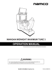
Deluxe Version
Owner’s Manual
SEGA ENTERPRISES, INC. USA
MANUAL NO. 4201-6478-01
VISIT OUR WEBSITE!
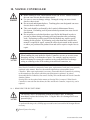
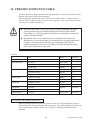
BEFORE USING THE PRODUCT, BE SURE TO READ THE FOLLOWING:
To maintain the safety:
To ensure the safe usage of the product, be sure to read the following before using the product. The following
instructions are intended for the users, operators and the personnel in charge of the operation of the product.
After carefully reading and sufficiently understanding the warning displays and cautions, handle the product
appropriately. Be sure to keep this manual nearby the product or elsewhere convenient for referring to it
when necessary.
Herein, explanations which require special attention are enclosed with dual lines. Depending on the potentially hazardous degrees, the terms of WARNING, CAUTION, etc. are used. Be sure to understand the
contents of the displays before reading the text.
Indicates that mishandling the
product by disregarding this
warning will cause a potentially
hazardous situation which can
result in death or serious injury.
Indicates that mishandling the product
by disregarding this caution will cause
a slight hazardous situation which can
result in personal injury and or material
damage.
For the sage usage of the product, the following pictographs are used:
Indicates “HANDLE WITH CARE.” In order to protect the human body an equipment, this
display is attached to places where the Owner’s Manual and or Service Manual should be referred
to.
Perform work in accordance with the instructions herein stated.
Instructions for work are explained by paying attention to the aspect of accident prevention. Failing to
perform work as per the instructions can cause accidents. In the case where only those who have technical expertise should perform the work to avoid hazardous situation, the instructions herein state that the
serviceman should perform such work.
Be sure to turn off power before working on the machine.
To prevent electric shock, be sure to turn off power before starting the work in which the worker touches
the interior of the product. If the work is to be performed in the power-on status, the Instruction Manual
herein always states to that effect.
Be sure to ground the Earth Terminal (this, however, is not required in the case where a power cord
with earth is used).
This product is equipped with the Earth Terminal. When installing the product, Connect the Earth Terminal to the “accurately grounded indoor earth terminal” by using an earth wire. Unless the product is
grounded appropriately, the user can be subject to electric shock. After performing repair, etc. for the
Control equipment, ensure that the Earth Wire is firmly connected to the Control equipment.
Ensure that the Power Supply used is equipped with an Earth Leakage Breaker.
This product does not incorporate the Earth Leakage Breaker. Using a power supply which is not
equipped with the Earth Leakage Breaker can cause a fire when earth leakage occurs.
Be sure to use fuses which meet the specified rating. (only for the machines which use fuses).
Using fuses exceeding the specified rating can cause a fire and electric shock.
Specification changes (removal of equipment, conversion and addition) not designated by SEGA
are not allowed.
The parts of the product include warning labels for safety, covers for personal protection, etc. It is very
hazardous to operate the product by removing parts and or modifying the circuits. Should doors, lids
and protective parts be damaged or lost, refrain from operating the product, and contact where the
product was purchased from or the office herein stated. SEGA shall not be held responsible for any
accidents, compensation for damage to a third party, resulting from the specifications not designated by
SEGA.
Ensure that the product meets the requirements of appropriate Electrical Specifications.
Before installing the product, check for Electrical Specifications. SEGA products have a nameplate on
which Electrical Specifications are described. Ensure that the product is compatible with the power
supply voltage and frequency requirements of the location. Using any Electrical Specifications different
from the designated Specifications can cause a fire and electric shock.
Install and operate the product in places where appropriate lighting is available, allowing warning
labels to be clearly read.
To ensure safety for the customers, labels and printed instructions describing potentially hazardous
situation are applied to places where accidents can be caused. Ensure that where the product is operated
has sufficient lighting allowing the warnings to be read. If any label is peeled off, apply it again immediately. Please place an order with where the product was purchased from or the office herein stated.
When handling the Monitor, be very careful. (Applies only to the product w/monitor.)
Some of the monitor (TV) parts are subject to high tension voltage. Even after running off power, some
portions are still subject to high tension voltage sometimes. Monitor repair and replacement should be
performed only be those technical personnel who have knowledge of electricity and technical expertise.
Be sure to adjust the monitor (projector) properly. (Applies only to the product w/monitor.)
Do not operate the product leaving on-screen flickering or blurring as it is. Using the product with the
monitor not properly adjusted may cause dizziness or a headache to an operator, a player, or the customers.
When transporting or reselling this product, be sure to attach this manual to the product.
In the case where commercially available monitors and printers are used in this product, only the
contents relating to this product are explained herein. Some commercially available equipment has
functions and reactions not stated in this manual. Read this manual together with the specific Instruction Manual of such equipment.
• Descriptions herein contained may be subject to improvement changes without notice.
• The contents described herein are fully prepared with due care. However, should any question arise or
errors be found, please contact SEGA.
INSPECTIONS IMMEDIATELY AFTER TRANSPORTING THE PRODUCT TO THE LOCATION.
Normally, at the time of shipment, SEGA products are in a status allowing for usage immediately after
transporting to the location. Nevertheless, an irregular situation may occur during transportation. Before
turning on power, check the following points to ensure that the product has been transported in a satisfactory status.
Are there any dented portions or defects (cuts, etc.) on the external surfaces of the cabinet?
Are Casters and Adjusters, damaged?
Do the power supply voltage and frequency requirements meet with those of the location?
Are all wiring connectors correctly and securely connected? Unless connected in the correct direction,
connector connections can not be made accurately. Do not insert connectors forcibly.
Do power cords have cuts and dents?
Do the fuses used meet specified rating? Is the Circuit Protector in an energized status?
Are all accessories available?
Can all Doors and Lids be opened with the Accessory keys? Can Doors and Lids be firmly closed?
TABLE OF CONTENTS
BEFORE USING THE PRODUCT, BE SURE TO READ THE FOLLOWING:
TABLE OF CONTENTS
INTRODUCTION OF THE OWNER’S MANUAL
1. HANDLING PRECAUTIONS ..........................................................................................
2. PRECAUTIONS CONCERNING INSTALLATION LOCATION ...................................
3. OPERATION .....................................................................................................................
4. NAME OF PARTS .............................................................................................................
5. ACCESSORIES .................................................................................................................
6. ASSEMBLING AND INSTALLATION ............................................................................
7. PRECAUTIONS TO BE HEEDED WHEN MOVING THE MACHINE ........................
8. CONTENTS OF GAME ....................................................................................................
9. EXPLANATION OF TEST AND DATA DISPLAY ........................................................
9 - 1 SWITCH UNIT AND COIN METER ............................................................
9 - 2 SYSTEM TEST MODE ..................................................................................
9 - 3 GAME TEST MODE ......................................................................................
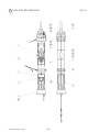
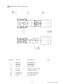
10. NOZZLE CONTROLLER................................................................................................
10 - 1 REMOVING THE SECURITY WIRE..........................................................
10 - 2 REMOVING THE ASSY SENSOR...............................................................
10 - 3 REMOVING THE NOZZLE CONTROLLER..............................................
10 - 4 DISASSEMBLING THE NOZZLE CONTROLLER...................................
11. COIN SELECTOR ...........................................................................................................
12. PROJECTOR........ ...........................................................................................................
12 - 1 CLEANING THE SCREEN..........................................................................
12 - 2 ADJUSTMENT OF TOSHIBA PROJECTOR...............................................
12 - 3 ADJUSTMENT OF MITSUBISHI PROJECTOR.........................................
13. REPLACING THE FLOURESCENT LAMP, AND LAMPS ..........................................
14. PERIODIC INSPECTION TABLE ..................................................................................
15. TROUBLESHOOTING ....................................................................................................
16. GAME BOARD ................................................................................................................
16 - 1 REMOVING THE GAME BOARD .............................................................
16 - 2 COMPOSITION OF GAME BOARD ..........................................................
17. DESIGN RELATED PARTS ............................................................................................
18. PARTS LIST .....................................................................................................................
19. WIRE COLOR CODE TABE ...........................................................................................
20. WIRING DIAGRAM ........................................................................................................
1
2-3
4-8
9
10 - 12
13 - 27
29
29 - 31
32 - 56
57
57 - 59
60
61 - 63
63 - 66
67 - 70
71 - 84
71
72 - 81
74
75 - 84
85 - 86
82 - 84
85 - 88
89
90 - 92
93 - 95
93 - 94
95
96
97 - 134
135
XXX
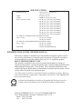
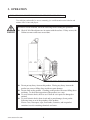
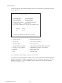
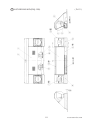
SPECIFICATIONS
Installation Space
: 1,290 mm (W) X 1720 mm (D)
(50.8 in. X 67.7 in.)
Height
: 2,190 mm (86.2 in.)
Weight
: APPROX. 295 kg. (650.4 lbs.)
Power, maximum current
: 491 W 5.47 A (AC 110V 50 Hz AREA)
485 W 5.43 A (AC 110V 60 Hz AREA)
466 W 4.82 A (AC 120V 60 Hz AREA)
489 W 2.82 A (AC 220V 50 Hz AREA)
507 W 2.89 A (AC 220V 60 Hz AREA)
515 W 2.80 A (AC 230V 50 Hz AREA)
464 W 2.55 A (AC 230V 60 Hz AREA)
470 W 2.48 A (AC 240V 50 Hz AREA)
470 W 2.44 A (AC 240V 60 Hz AREA)
For TAIWAN (TOSHIBA POJECTION DISPLAY TYPE)
Power, current
: 530 W 5.20 A (MAX.)
330 W 3.60 A (MIN.)
For TAIWAN (MITSUBISHI POJECTION DISPLAY TYPE)
Power, current
: 530 W 5.50 A (MAX.)
320 W 3.40 A (MIN.)
MONITOR
: 50 INCH COLOR MONITOR
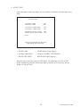
INTRODUCTION OF THE OWNERS MANUAL
This Owner's Manual is intended to provide detailed descriptions together with all
the necessary information covering the general operation of electronic assemblies,
electromechanicals, servicing control, spare parts, etc. as regards the product,
BRAVE FIREFIGHTERS DX TYPE.
This manual is intended for the owners, personnel and managers in charge of
operation of the product. Operate the product after carefully reading and sufficiently
understanding the instructions. If the product fails to function satisfactorily, nontechnical personnel should under no circumstances touch the internal system. Please
contact where the product was purchased from.
Use of this product is unlikely to cause physical injuries or damages to property. However,
where special attention is required this is indicated by a thick line, the word "IMPORTANT"
and its sign in this manual.
STOP
Indicates that mishandling the product by disregarding this display can cause the
product's intrinsic performance not to be obtained, resulting in malfunctioning.
IMPORTANT
SEGA ENTERPRISES, INC. (U.S.A.)/CUSTOMER SERVICE
45133 Industrial Drive, Fremont, California 94538, U.S.A.
Phone : (415) 701-6580
Fax : (415) 701-6594
DEFINITION OF LOCATION MAINTENANCE MAN AND SERVICEMAN
Non-technical personnel who do not have technical knowledge and expertise should
refrain from performing such work that this manual requires the location's
maintenance man or a serviceman to carry out, or work which is not explained in
this manual. Failing to comply with this instruction can cause a severe accident
such as electric shock.
Ensure that parts replacement, servicing & inspections, and troubleshooting are performed by the
location's maintenance man or the serviceman. It is instructed herein that particularly hazardous
work should be performed by the serviceman who has technical expertise and knowledge.
The location's maintenance man and serviceman are herein defined as follows:
"Location's Maintenance Man" :
Those who have experience in the maintenance of amusement equipment and vending machines,
etc., and also participate in the servicing and control of the equipment through such routine work
as equipment assembly and installation, servicing and inspections, replacement of units and
consumables, etc. within the Amusement Facilities and or locations under the management of the
Owner and Owner's Operators of the product.
Activities of Location's Maintenance Man :
Assembly & installation, servicing & inspections, and replacement of units & consumables as
regards amusement equipment, vending machines, etc.
Serviceman :
Those who participate in the designing, manufacturing, inspections and maintenance service of
the equipment at an amusement equipment manufacturer.
Those who have technical expertise equivalent to that of technical high school graduates as regards electricity, electronics and or mechanical engineering, and daily take part in the servicing &
control and repair of amusement equipment.
Serviceman's Activities :
Assembly & installation and repair & adjustments of electrical, electronic and mechanical parts of
amusement equipment and vending machines.
LISTED
UL
5K92
®
AMUSEMENT MACHINE
1. HANDLING PRECAUTIONS
When installing or inspecting the machine, be very careful of the following points and pay
attention to ensure that the player can enjoy the game safely.
Non-compliance with the following points or inappropriate handling running counter to the
cautionary matters herein stated can cause personal injury or damage to the machine.
Before performing work, be sure to turn power off. Performing the work
without turning power off can cause an electric shock or short circuit. In the
case work should be performed in the status of power on, this manual always
states to that effect.
To avoid electric shock or short circuit, do not plug in or unplug quickly.
To avoid electric shock, do not plug in or unplug with a wet hand.
Do not expose Power Cords and Earth Wires on the surface, (floor, passage,
etc.). If exposed, the Power Cords and Earth Wires are susceptible to damage.
Damaged cords and wires can cause electric shock or short circuit.
To avoid causing a fire or electric shock, do not put things on or damage
Power Cords.
When or after installing the product, do not unnecessarily pull the power cord.
If damaged, the power cord can cause a fire or electric shock.
In case the power cord is damaged, ask for replacement through where the
product was purchased from or the office herein stated. Using the cord as is
damaged can cause fire, electric shock or leakage.
Be sure to perform grounding appropriately. Inappropriate grounding can
cause an electric shock.
Be sure to use fuses meeting specified rating. Using fuses exceeding the
specified rating can cause a fire or electric shock.
Completely make connector connections for IC BD and others. Insufficient
insertion can cause an electric shock.
To avoid causing a fire or electric shock, do not make Specification changes
by removing, converting and making additions unless otherwise designated by
SEGA.
Be sure to perform periodic maintenance inspections herein stated.
STOP
IMPORTANT!
For the IC board circuit inspections, only the logic tester is allowed. The use
of a multiple-purpose tester is not permitted, so be careful in this regard.
The Projector is employed for this machine. The Projector's screen is
susceptible to damage, therefore, be very careful when cleaning the screen.
For details, refer to PROJECTOR.
1
www.seuservice.com
2. PRECAUTIONS CONCERNING INSTALLATION
LOCATION
This product is an indoor game machine. Do not install it outside. Even indoors,
avoid installing in places mentioned below so as not to cause a fire, electric shock,
injury and or malfunctioning.
Places subject to rain or water leakage, or places subject to high humidity in
the proximity of an indoor swimming pool and or shower, etc.
Places subject to direct sunlight, or places subject to high temperatures in the
proximity of heating units, etc.
Places filled with inflammable gas or vicinity of highly inflammable/volatile
chemicals or hazardous matter.
Dusty places.
Sloped surfaces.
Places subject to any type of violent impact.
Vicinity of anti-disaster facilities such as fire exits and fire extinguishers.
The operating (ambient) temperature range is from 5° C to 40° C.
Only in the case a projector is employed, the temperature range is from 5° Cto
30° C.
LIMITATIONS OF USAGE REQUIREMENTS
Be sure to check the Electrical Specifications.
Ensure that this product is compatible with the location's power supply,
voltage and frequency requirements.
A plate describing Electrical Specifications is attached to the product.
Non-compliance with the Electric Specifications can cause a fire and electric
shock.
This product requires the Breaker and Earth Mechanisms as part of the
location facilities. Using them in a manner not independent can cause a fire
and electric shock.
Ensure that the indoor wiring for the power supply is rated at 15A or higher
(AC single phase 100 ~ 120V area), and 7A or higher (AC 220 ~ 240V area).
Non-compliance with the Electrical Specifications can cause a fire and
electric shock.
Be sure to independently use the power supply equipped with the Earth
Leakage Breaker. Using a power supply without the Earth Leakage Breaker
can cause an outbreak of fire when earth leakage occurs.
Putting many loads on one electrical outlet can cause generation of heat and a
fire
resulting from overload.
When using an extension cord, ensure that the cord is rated at 15A or higher
(AC 100 ~ 120V area) and 7A or higher (AC 220 ~ 240V area). Using a cord
rated lower than the specified rating can cause a fire and electric shock.
www.seuservice.com
2
Electric current consumption
MAX. 5.47 A (AC 110V 50 Hz)
MAX. 5.43 A (AC 110V 60 Hz)
MAX. 4.82 A (AC 120V 60 Hz)
MAX. 2.82 A (AC 220V 50 Hz)
MAX. 2.89 A (AC 220V 60 Hz)
MAX. 2.80 A (AC 230V 50 Hz)
MAX. 2.55 A (AC 230V 60 Hz)
MAX. 2.48 A (AC 240V 50 Hz)
MAX. 2.44 A (AC 240V 60 Hz)
MAX. 5.20 A (For TAIWAN,TOSHIBA projection display)
MAX. 5.50 A (For TAIWAN,MITSUBISHI projection display)
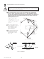
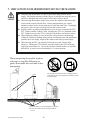
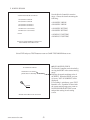
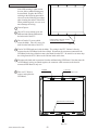
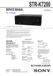
IMPORTANT!
For transporting the machine into the location's building, the minimum
necessary dimensions of the opening (of doors, etc.) are 1.3m(W) and
1.6m(H).
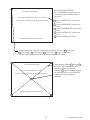
For the operation of this machine, secure a minimum area of 1.5m (W) X 2.5m
(D). For ventilation, provide an approximately 10cm. space between the rear
part of the cabinet and the wall.
2.5m -98.43 inches
STOP
1234567890123456789012345678901212345678901234567890123456789012123456789
1234567890123456789012345678901212345678901234567890123456789012123456789
1234567890123456789012345678901212345678901234567890123456789012123456789
1234567890123456789012345678901212345678901234567890123456789012123456789
1234567890123456789012345678901212345678901234567890123456789012123456789
1234567890123456789012345678901212345678901234567890123456789012123456789
1234567890123456789012345678901212345678901234567890123456789012123456789
1234567890123456789012345678901212345678901234567890123456789012123456789
1234567890123456789012345678901212345678901234567890123456789012123456789
1234567890123456789012345678901212345678901234567890123456789012123456789
1234567890123456789012345678901212345678901234567890123456789012123456789
1234567890123456789012345678901212345678901234567890123456789012123456789
1234567890123456789012345678901212345678901234567890123456789012123456789
Approx.10cm=
1234567890123456789012345678901212345678901234567890123456789012123456789
1234567890123456789012345678901212345678901234567890123456789012123456789
1234567890123456789012345678901212345678901234567890123456789012123456789
1234567890123456789012345678901212345678901234567890123456789012123456789
39.4 in
1234567890123456789012345678901212345678901234567890123456789012123456789
1234567890123456789012345678901212345678901234567890123456789012123456789
1234567890123456789012345678901212345678901234567890123456789012123456789
1234567890123456789012345678901212345678901234567890123456789012123456789
1234567890123456789012345678901212345678901234567890123456789012123456789
1234567890123456789012345678901212345678901234567890123456789012123456789
1234567890123456789012345678901212345678901234567890123456789012123456789
1234567890123456789012345678901212345678901234567890123456789012123456789
1234567890123456789012345678901212345678901234567890123456789012123456789
1234567890123456789012345678901212345678901234567890123456789012123456789
1234567890123456789012345678901212345678901234567890123456789012123456789
1234567890123456789012345678901212345678901234567890123456789012123456789
1234567890123456789012345678901212345678901234567890123456789012123456789
1234567890123456789012345678901212345678901234567890123456789012123456789
1234567890123456789012345678901212345678901234567890123456789012123456789
1234567890123456789012345678901212345678901234567890123456789012123456789
1234567890123456789012345678901212345678901234567890123456789012123456789
1234567890123456789012345678901212345678901234567890123456789012123456789
1234567890123456789012345678901212345678901234567890123456789012123456789
1234567890123456789012345678901212345678901234567890123456789012123456789
1234567890123456789012345678901212345678901234567890123456789012123456789
1234567890123456789012345678901212345678901234567890123456789012123456789
1234567890123456789012345678901212345678901234567890123456789012123456789
1234567890123456789012345678901212345678901234567890123456789012123456789
1234567890123456789012345678901212345678901234567890123456789012123456789
1234567890123456789012345678901212345678901234567890123456789012123456789
1234567890123456789012345678901212345678901234567890123456789012123456789
1234567890123456789012345678901212345678901234567890123456789012123456789
1234567890123456789012345678901212345678901234567890123456789012123456789
1234567890123456789012345678901212345678901234567890123456789012123456789
1234567890123456789012345678901212345678901234567890123456789012123456789
1234567890123456789012345678901212345678901234567890123456789012123456789
1234567890123456789012345678901212345678901234567890123456789012123456789
1234567890123456789012345678901212345678901234567890123456789012123456789
1234567890123456789012345678901212345678901234567890123456789012123456789
1234567890123456789012345678901212345678901234567890123456789012123456789
1234567890123456789012345678901212345678901234567890123456789012123456789
1234567890123456789012345678901212345678901234567890123456789012123456789
1234567890123456789012345678901212345678901234567890123456789012123456789
1234567890123456789012345678901212345678901234567890123456789012123456789
1234567890123456789012345678901212345678901234567890123456789012123456789
1234567890123456789012345678901212345678901234567890123456789012123456789
1234567890123456789012345678901212345678901234567890123456789012123456789
1234567890123456789012345678901212345678901234567890123456789012123456789
1234567890123456789012345678901212345678901234567890123456789012123456789
1234567890123456789012345678901212345678901234567890123456789012123456789
1234567890123456789012345678901212345678901234567890123456789012123456789
1234567890123456789012345678901212345678901234567890123456789012123456789
1234567890123456789012345678901212345678901234567890123456789012123456789
1234567890123456789012345678901212345678901234567890123456789012123456789
1234567890123456789012345678901212345678901234567890123456789012123456789
1234567890123456789012345678901212345678901234567890123456789012123456789
1234567890123456789012345678901212345678901234567890123456789012123456789
1234567890123456789012345678901212345678901234567890123456789012123456789
1234567890123456789012345678901212345678901234567890123456789012123456789
1234567890123456789012345678901212345678901234567890123456789012123456789
Approx.
Approx.
1234567890123456789012345678901212345678901234567890123456789012123456789
1234567890123456789012345678901212345678901234567890123456789012123456789
1234567890123456789012345678901212345678901234567890123456789012123456789
10cm=
1234567890123456789012345678901212345678901234567890123456789012123456789
10cm=
1234567890123456789012345678901212345678901234567890123456789012123456789
1234567890123456789012345678901212345678901234567890123456789012123456789
1234567890123456789012345678901212345678901234567890123456789012123456789
39.4 in
39.4 in
1234567890123456789012345678901212345678901234567890123456789012123456789
1234567890123456789012345678901212345678901234567890123456789012123456789
1234567890123456789012345678901212345678901234567890123456789012123456789
1234567890123456789012345678901212345678901234567890123456789012123456789
1234567890123456789012345678901212345678901234567890123456789012123456789
1234567890123456789012345678901212345678901234567890123456789012123456789
1234567890123456789012345678901212345678901234567890123456789012123456789
1234567890123456789012345678901212345678901234567890123456789012123456789
1234567890123456789012345678901212345678901234567890123456789012123456789
1234567890123456789012345678901212345678901234567890123456789012123456789
1234567890123456789012345678901212345678901234567890123456789012123456789
1234567890123456789012345678901212345678901234567890123456789012123456789
1234567890123456789012345678901212345678901234567890123456789012123456789
1234567890123456789012345678901212345678901234567890123456789012123456789
1234567890123456789012345678901212345678901234567890123456789012123456789
1234567890123456789012345678901212345678901234567890123456789012123456789
1234567890123456789012345678901212345678901234567890123456789012123456789
1234567890123456789012345678901212345678901234567890123456789012123456789
1234567890123456789012345678901212345678901234567890123456789012123456789
1234567890123456789012345678901212345678901234567890123456789012123456789
1234567890123456789012345678901212345678901234567890123456789012123456789
1234567890123456789012345678901212345678901234567890123456789012123456789
1234567890123456789012345678901212345678901234567890123456789012123456789
1234567890123456789012345678901212345678901234567890123456789012123456789
1234567890123456789012345678901212345678901234567890123456789012123456789
1234567890123456789012345678901212345678901234567890123456789012123456789
1234567890123456789012345678901212345678901234567890123456789012123456789
1234567890123456789012345678901212345678901234567890123456789012123456789
1234567890123456789012345678901212345678901234567890123456789012123456789
1234567890123456789012345678901212345678901234567890123456789012123456789
1234567890123456789012345678901212345678901234567890123456789012123456789
1234567890123456789012345678901212345678901234567890123456789012123456789
1234567890123456789012345678901212345678901234567890123456789012123456789
1234567890123456789012345678901212345678901234567890123456789012123456789
1234567890123456789012345678901212345678901234567890123456789012123456789
1234567890123456789012345678901212345678901234567890123456789012123456789
1234567890123456789012345678901212345678901234567890123456789012123456789
1234567890123456789012345678901212345678901234567890123456789012123456789
1234567890123456789012345678901212345678901234567890123456789012123456789
1.5m=59.1 in
FIG. 2
3
www.seuservice.com
3. OPERATION
PRECAUTIONS TO BE HEEDED BEFORE STARTING THE OPERATION
To avoid injury and trouble, be sure to constantly give careful attention to the behavior and
manner of the visitors and players.
In order to avoid accidents, check the following before starting the operation:
Check if all of the adjusters are in contact with the surface. If they are not, the
Cabinet can move and cause an accident.
Ensure that all of the Adjusters are in contact with the floor.
Do not put any heavy item on this product. Placing any heavy item on the
product can cause a falling down accident or parts damage.
Do not climb on the product. Climbing on the product can cause falling down
accidents. To check the top portion of the product, use a step.
To avoid electric shock, check to see if door & cover parts are damaged or
omitted.
To avoid electric shock, short circuit and or parts damage, do not put the
following items on or in the periphery of the product.
Flower vases, flowerpots, cups, water tanks, cosmetics, and receptacles/
containers/vessels containing chemicals and water.
www.seuservice.com
4
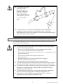
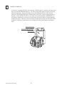
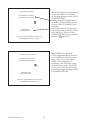
The Security Wire is an
important accident
preventative part. If
damaged, immediately
replace the Security
Wire. Using the Wire as
is damaged for operation
can cause personal
injury.
To avoid injury, be sure to provide sufficient space by considering the
potentially crowded situation at the installation location. Insufficient
installation space can cause the customers to come into contact with or hit the
others and result in injury or trouble.
PRECAUTIONS TO BE HEEDED DURING OPERATION ( PAYING ATTENTION TO CUSTOMERS ).
To avoid injury and trouble, be sure to constantly give careful attention to the behavior and
manner of the visitors and players.
To avoid injury and accidents, those who fall under the following categories
are not allowed to play the game.
• Those who need assistance such as the use of an apparatus when walking.
• Those who have high blood pressure or a heart problem.
• Those who have experienced muscle convulsion or loss of consciousness when
playing video game, etc.
• Those who have a trouble in the neck and or spinal cord.
• Intoxicated persons.
• Pregnant women or those who are in the likelihood of pregnancy.
• Persons susceptible to motion sickness.
• Persons whose act runs counter to the product's warning displays.
To avoid injury resulting from falling down, and electric shock due to spilled
drinks, instruct the player not to place heavy items or drinks on the product.
To avoid electric shock and short circuit, do not allow customers to put hands
and fingers or extraneous matter in the openings of the product or small
openings in or around the doors.
To avoid falling down and injury resulting from falling down, immediately
stop the customer's leaning against or climbing on the product, etc.
To avoid electric shock and short circuit, do not allow the customers to
unplug the power plug without a justifiable reason.
5
www.seuservice.com
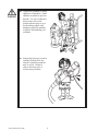
Caution the guardians of small
children to watch them. Small
children are unable to perceive
hazards. Use care so that they
do not come close to the
product when in play so as to
avoid making contact with,
bumping against the machine
or players, and tumbling over
accidents.
Instruct the players so as not to
wind the Security Wire for
Nozzle Controller around his
neck or wrists. Failure to
observe this may cause a
serious injury accident.
www.seuservice.com
6
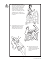
Instruct the player(s) to securely
hold Nozzle Controller when playing
the game. Instruct the player(s) to
suspend strap from his shoulder as
much as possible. The Nozzle
Controller weighs approximately
1.8Kg and sways during game play.
Dropping Nozzle Controller can
cause the player(s) or other people to
be injured.
Caution the player(s) so as not to
brandish the Nozzle Controller.
Hitting other people by Nozzle
Controller can cause an injury.
Instruct the player(s) to be
careful not to have fingers
pinched in when returning the
Nozzle Controller to its
position.
7
www.seuservice.com
Instruct the person(s) who has a disorder with hands or arms to refrain from
playing the game by explaining that playing the game may cause the
worsening of his condition.
Caution the player(s) so as not
to hold a Nozzle Controller by
2 or more Players to play the
game. Failure to observe this
may cause collisions or near
collisions.
Immediately stop such violent acts as hitting and kicking the product. Such
violent acts can cause parts damage or falling down, resulting in injury due to
fragments and falling down.
www.seuservice.com
8
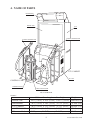
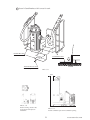
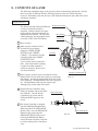
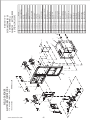
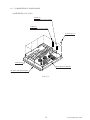
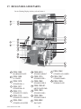
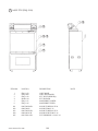
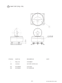
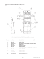
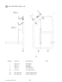
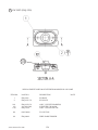
4. NAME OF PARTS
BILLBOARD
PROJECTOR
PTV
2P SIDE CONTROLLER
1P SIDE CONTROLLER
PTV CABINET
AC UNIT
CONTROL CABI
CASHBOX DOOR
COIN CHUTE DOOR
FIG. 4 OVERVIEW
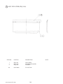
TABLE 4
Width
PROJECTOR
BILLBOARD
PTV CABINET
CONTROL CABI
When assembled
X
Length
44.9” [1,140 mm] X 20.9” [530 mm]
44.9” [1,140 mm] X 20.9” [530 mm]
44.9” [1,140 mm] X 33.5” [850 mm]
51.2” [1,300 mm] X 41.7” [1,060 mm]
51.2” [1,300 mm] X 67.7” [1,720 mm]
9
X
Height
Weight
X 62.2” [1,580 mm] 200.2 lbs (91 kg)
X 13.4” [340 mm]
61.6 lbs (28 kg)
X 37.0” [940 mm]
160.6 lbs (73 kg)
X 43.7” [1,110 mm] 178.2 lbs (81 kg)
X 86.2” [2,190 mm] 649.0 lbs (295 kg)
www.seuservice.com
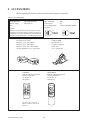
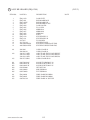
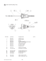
5. ACCESSORIES
When transporting the machine, make sure that the following parts are supplied.
TABLE 5 ACCESSORIES
DESCRIPTION
Part No. (Qty.)
Note
KEY MASTER
220-5576 (2)
For opening/closing
the doors
OWNERS MANUAL
420-6478-01 (1)
Figures
KEY
(2)
For the CASHBOX DOOR
If Part No. has no description, the Number has not been
registered or can not be registered. Such a part may not
be obtainable even if the customer desires to purchase it.
Therefore, ensure that the part is in safekeeping with you.
AC Cable (Power Cord)
600-6729 (1) AC 110V AREA
600-6695 (1) AC 120V AREA
600-6618 (1) AC 220 ~ 240V AREA
Used for installation, see 4 of Section 6.
CORD CLAMP
280-5009-01 (1)
Used for securing the
power cord.
see 4 of Section 6.
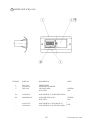
TOSHIBA
Remote Control for Projector
Used for adjustment.
See Section 12.
200-5536(1)
TEST
MODE
WRITING
R
G
B
MITSUBISHI
Remote Control for Projector
Used for adjustment.
See Section 12.
200-5532(1)
P
POWER
SET
R / B
POSITION
R / G / B
PIC-ADJ
TEST
1
ADJUST
RESET
ENTER
8
9
10
R-MUTE G-MUTE B-MUTE
-- PICTURE +
SELECT
MITSUBISHI
One of the above 2 types of
Remote Controls is used for the
Projector.
www.seuservice.com
10
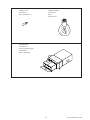
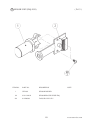
LAMP 6V 3W
390-5160 (1)
Spare, see Section 13.
LAMP 120V 40W
390-6648 (2)
Spare,
see Section 13.
CARTON BOX
601-10642 (1)
Used for transporting the
Game Board.
Refer to Next Page.
CH
EC
K
SI
11
DE
www.seuservice.com
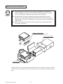
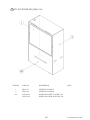
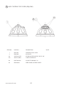
HOW TO USE THE CARTON BOX
STOP
IMPORTANT!
When asking for the replacement or repair of the product's Game Board
(SEGA HIKARU), be sure to put the Game Board together with the Shield
Case in a Carton Box. Otherwise, the request is not acceptable.
Put the Shield Case in the Carton Box by paying attention to the correct
direction as per the following instructions and as shown by the instructions
printed on the Carton Box. Handling in an erroneous manner can damage the
Game Board.
Remove the Shield Case Brackets from the Shield Case and put the Shield
Case in the Carton Box.
SHIELD CASE BRACKETS
The shape depends on the type of product.
"CHECK SIDE" Display
CH
EC
K
SI
DE
FILTER BOARD
Wrap the Shield Case with the packing material and put it in the Carton Box as shown. Putting
it upside down or packing otherwise in the manner not shown can damage the Game Board and
parts.
www.seuservice.com
12
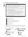
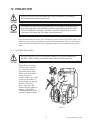
6. ASSEMBLING AND INSTALLATION
Perform assembly work by following the procedure herein stated. Failing to
comply with the instructions can cause electric shock hazard.
Assembling should be performed as per this manual. Since this is a complex
machine, erroneous assembling can cause an electric shock, machine damage
and or not functioning as per specified performance.
When assembling, be sure to use plural persons. Depending on the assembly
work, there are some cases in which working by one person alone can cause
personal injury or parts damage.
Perform connector connection securely. Insufficient insertion can cause
electric shock and short circuit hazards.
This work should be performed by the Location's Maintenance Man or
Serviceman. Working by those who do not have technical expertise can cause
such severe accidents as electric shock. Failing to perform work in
accordance with the explanations given in this manual can cause such severe
accidents as electric shock to the player during operation.
Be careful so as not to damage wiring. Damaged wiring can cause electric
shock and short circuit hazards.
When carrying out the assembling and installation, follow the following 6-item sequence.
1
2
3
4
5
6
ASSEMBLING THE PTV
ASSEMBLING THE CABINET
SECURING IN PLACE (ADJUSTER ADJUSTMENT)
POWER SUPPLY, AND EARTH CONNECTION
TURNING POWER ON
ASSEMBLY CHECK
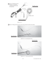
The master key (accessories) in addition to the tools such as a Phillips type screwdriver, wrench
for M16 hexagon bolt, socket wrench for M8 hexagon bolt, Ratchet Handle are required for the
assembly work.
Phillips type screwdriver
24mm
WRENCH (for M16 hexagon bolt)
SOCKET WRENCH,(for M8 hexagon bolt)
RATCHET HANDLE
KEY MASTER
13
www.seuservice.com
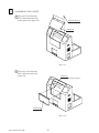
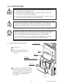
1
ASSEMBLING THE PTV
To perform work safely and securely, be sure to prepare a step which is in a
secure and stable condition. Performing work without using the step can cause
violent falling down accidents.
1 By using 2 Flat Head screws, secure the 2 Mask Bracket Uppers to the PTV ceiling.
2 Secure the Mask Bracket Lower to the front of PTV with 4 screws.
FLAT HEAD SCREW (2 each)
M4 X 14
MASK BRACKET UPPER
MASK BRACKET LOWER
TRUSS SCREW (4)
M5 X 20
FIG. 6. 1 a
www.seuservice.com
14
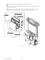
3 Install the Mask to the PTV
front. Install the Mask in a
manner hooking up to both 2
Mask Bracket Uppers and
the Mask Bracket Lower.
Simultaneously insert the
projections of the Mask into
the square holes in the PTV
Screen left and right.
TRUSS SCREW (2)
M5 X 25,flat washer used.
4 Secure the Mask by
fastening a screw for each
from both sides of PTV.
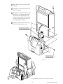
5 Connect 2 Wire Connectors
of the Billboard to the PTV
ceiling. At this time,
connect the Connectors with
using a step while another 2
persons supporting the
BILLBOARD for
performing work safely.
MASK
6 Mount the BILLBOARD onto the PTV and
FIG. 6. 1 b
move the BILLBOARD to the PTV screen
direction while hooking up the Billboard to
the 2 Mask Bracket Uppers. Be careful so
as not to damage the wiring at this time.
7 Secure the BILLBOARD with 2 screws.
SCREW (2)
M5 X 16,w/flat & spring washers
BILLBOARD
Connect the Connector
When performing work,
prepare a step.
FIG. 6. 1 c
15
www.seuservice.com
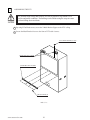
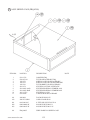
2
ASSEMBLING THE CABINET
1 Take out 2 screws from the
PTV Cabinet and unlock the
lock to remove the Upper Lid.
TRUSS SCREW (2)
M4 X 20
UPPER LID
FIG. 6. 2 a
2 Take out 2 screws from the
PTV Cabinet to remove the
Lower Lid.
SCREW (2)
M4 X 25,w/flat & spring washers
LOWER LID
FIG. 6. 2 b
www.seuservice.com
16
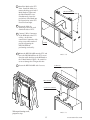
3 Move the PTV to the rear of the PTV
Cabinet.
PTV
4 Connect the wiring between the PTV
and PTV Cabinet.
5 Mount PTV on the PTV Cabinet. Lift
the PTV by 3 or more persons while
another person supporting the PTV
Cabinet so as not to cause the Cabinet
to move. At this time, use care so as
not to damage the wiring.
6 Secure the joint portion of PTV and
the PTV Cabinet with 4 screws.
Perform wiring connection.
TRUSS SCREW (4)
M5 X 30,flat washer used.
FIG. 6. 2 c
For performing work, use 4 or more workers.
17
www.seuservice.com
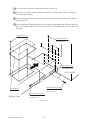
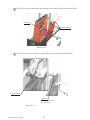
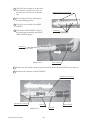
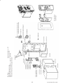
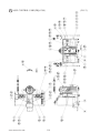
7 Take out 6 screws from the Control Cabi to remove Center Lid.
8 Insert the Control Cabi into the square hole in the PTV Cabinet. At this time, be careful so as
not to damage the wiring.
9 Fasten 4 Hexagon bolts to the bottom base of PTV Cabinet to secure the joint of PTV Cabinet
and Control Cabi.
10 Secure Joint Bracket L&R to the both sides of Cabinet's joint portion with 4 Hexagon Bolts for
each. The length of Bolts used for Control Cabi and for PTV Cabinet differ. Be very careful of
this point.
TRUSS SCREW (6)
M4 X 12
HEXAGON BOLT (4)
M8 X 40,w/spring washer,
flat washer used.
JOINT BRACKET R
(OPPOSITE SIDE)
JOINT BRACKET L
PTV CABINET
HEXAGON BOLT (2 each)
M8 X 20,w/spring washer,
flat washer used.
CENTER LID
CONTROL CABI
HEXAGON BOLT (2 each)
M8 X 40,w/spring washer,
flat washer used.
FIG. 6. 2 d
www.seuservice.com
18
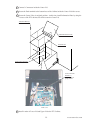
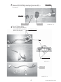
11 Connect 2 Connectors inside the Center Lid.
12 Secure the Earth terminal to the bottom base of the Cabinet inside the Center Lid with a screw.
13 Secure the Center Lid to its original position. At this time, install Information Plate by using the
2 screws of the PTV cabinet side which secure the Center Lid.
TRUSS SCREW (6)
M4 X 12
INFORMATION PLATE
CENTER LID
Connect the Connectors.
Connect the Earth.
SCREW (1)
M4 X 8,w/flat &
spring washers
FIG. 6. 2 e
14 Install in order of Lower Lid and Upper Lid to the PTV Cabinet.
19
www.seuservice.com
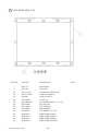
3
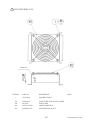
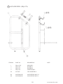
SECURING IN PLACE (ADJUSTER ADJUSTMENT)
Make sure that all of the adjusters are in contact with the floor. If they are not, the
cabinet can move and cause an accident.
1 This product has 8 casters (4 for PTV Cabinet, 4 for CONTROL CABI) and 11 Adjusters
(4 for PTV Cabinet, 7 for CONTROL CABI). (FIG. 6. 3a) When the installation position is
determined, cause the adjusters to come into contact with the floor directly, make adjustments in
a manner so that the casters will be raised approximately 5mm. from the floor and make sure
that the machine position is level.
Transport the product to the
installation position. When
installing the product near the wall,
be sure to secure the passage space
to allow player to get in the
machine.
ADJUSTER
2 Have all of the Adjusters make
contact with the floor. Adjust the
Adjuster's height by using a
wrench so that the machine
position is kept level.
3 After making adjustment, fasten
the Adjuster Nut upward and
secure the height of Adjuster
(FIG. 6. 3 b).
CASTER
FIG. 6. 3 a BOTTOM VIEW
ADJUSTER
CASTER
FASTEN UPWARD.
Approx.5mm
ADJUSTER
FIG. 6. 3 b ADJUSTER
www.seuservice.com
20
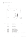
4 Secure 2 Guard Brackets with 2 screws for each.
GUARD BRACKET
GUARD BRACKET
TRUSS SCREW (2 each)
M4 X 12,large washers used
FLOOR
FIG. 6. 3 c
10cm
FIG. 6. 3 d
FIG. 6. 3 e
Refer to this Fig. (Scale:1/100)
for the layout of the place of
installation.
Provide ventilation space for the ventilation opening.
21
www.seuservice.com
4
POWER SUPPLY, AND EARTH CONNECTION
Be sure to independently use the power supply socket outlet equipped with an
Earth Leakage Breaker. Using a power supply without an Earth Leakage
Breaker can cause a fire when electric leakage occurs.
Ensure that the "accurately grounded indoor earth terminal" and the earth wire
cable are available (except in the case where a power cord plug with earth is
used). This product is equipped with the earth terminal. Connect the earth
terminal and the indoor earth terminal with the prepared cable. If the
grounding work is not performed appropriately, customers can be subjected to
an electric shock, and the product's functioning may not be stable.
Ensure that the power cord and earth wire are not exposed on the surface
(passage, etc.). If exposed, they can be caught and are susceptible to damage.
If damaged, the cord and wire can cause electric shock and short circuit
accidents. Ensure that the wiring position is not in the customer's passage
way or the wiring has protective covering.
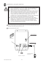
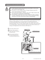
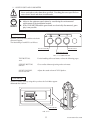
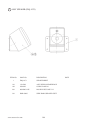
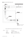
1 The AC Unit is located on one side of PTV Cabinet. The AC Unit has Main SW, Earth Terminal and the Inlet which connects the Power Cord.
2 Ensure that the Main SW is OFF.
EARTH TERMINAL
Connect with the
indoor earth terminal.
Main SW off
AC Cable (Power Cord)
INLET
To the Power Supply
Socket outlet
FIG. 6. 4 a AC unit
www.seuservice.com
22
3 Connect one end of the earth wire to
the AC Unit earth terminal, and the
other end to the indoor earth terminal.
The AC Unit earth terminal has a Bolt
and Nut combination. Take off the
Nut, pass the end of earth wire
through the Bolt, and fasten the Nut.
Note that the Earth Wire is
incorporated in the Power Cord for
the Areas of AC 120V (USA) and AC
220 ~ 240V, and therefore, this
procedure is not necessary.
Connect the Earth Wire
to the Earth Terminal.
FIG. 6. 4 b Earth Wire Connection
4 Firmly insert the power plug into
the socket outlet.
Insert the opposite side of Power
Cord plug to the AC Unit's connector ("INLET").
5 Perform wiring for the Power Cord
and Earth Wire. Install protective
covering for the Power Cord and
Earth Wire.
Wiring Cover
FIG. 6. 4 c Connecting Power Cord and Earth Wire
In case the Power Plug is apt to come out of place, secure
the Power Cord to the periphery of the AC Unit with the
Cord Clamp (an accessory).
HOW TO USE THE CORD CLAMP
23
www.seuservice.com
5
TURNING POWER ON
Turn the AC Unit Main SW ON to turn on power. When the power is turned on, the fluorescent
lamp inside the BILLBOARD lights up. The 2 Revolving lamps light up and turns round only
during the game play. The screen displays the System Starting mode for a while and then
proceeds to the ADVERTISE mode. Simultaneously at this time, sound is emitted from the 2
Speakers. If NO SOUND OUTPUT is set, sound is not emitted during the ADVERTISE. In
this product, turning power off does not clear the data such as the number of credits, Ranking,
and the latest point. Therefore, if power is turned on again after turning it off when play worth
credits are remaining, the game start screen is displayed on the monitor and the start buttons
flash.
Fluorescent lamp is lit.
On-screen images are outputted.
Sound is emitted.
www.seuservice.com
24
THE INTERFERENCE PREVENTION WIRING
In order to prevent electric shock and short circuit hazards, be sure to turn
power off before performing work.
Be careful so as not to damage wirings. Damaged wiring can cause fire,
electric shock and short circuit hazards.
Do not expose the IC BD, etc. without a good reason. Failure to observe this
can cause electric shock hazard or malfunctioning.
Work should be performed by the Location's Maintenance Man or technical
personnel. Performing work by those who do not have technical knowledge
and expertise can cause electric shock accident or malfunctioning.
When the identical machines are put side by side, the machines might malfunction due to the
interference of the Sight Sensor. To prevent interference, disconnect the Interference
Prevention Wiring from the Gun Sensor BD in either one of the 2 machines put as per the
following procedures. In case 3 or more identical machines are put side by side, use the Wiring
on every other machine. Further, the interference might occur on the cabinet which uses the
same type of the Sight Sensor such as The House of the Dead 2, etc.
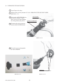
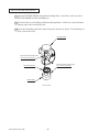
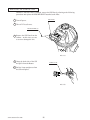
1 Turn off the Cabinet's power.
TRUSS SCREW (6)
M4 X 12
2 Take out 6 Truss screws to
INFORMATION PLATE
remove the Center Lid and the
Information Plate.
3 Disconnect the Interference
Prevention Wiring from the
Gun Sensor BD inside the Lid.
CENTER LID
GUN SENSOR BD
INTERFERENCE PREVENTION WIRING
HOD-60040
25
www.seuservice.com
6
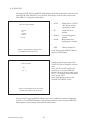
ASSEMBLING CHECK
In the TEST MODE, ensure that the assembly has been made correctly and IC BD. is satisfactory
(refer to Section 9).
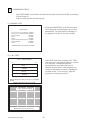
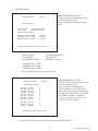
In the test mode, perform the following test:
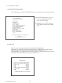
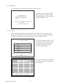
(1) MEMORY TEST
Selecting the RAM TEST on the test mode menu
screen causes the on-board memory to be tested
automatically. The game board is satisfactory if
the display beside each IC No. shows GOOD.
RAM TEST
IC15 IC16 IC17S IC18S
IC22 IC23 IC24S IC25S
IC28 IC29S
IC41
IC42
IC44 IC45S IC46 IC47S
IC91S IC92S
IC98
GOOD
GOOD
GOOD
GOOD
GOOD
GOOD
GOOD
GOOD
PRESS TEST BUTTON TO EXIT
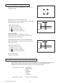
(2) C.R.T. TEST
C.R.T. TEST PAGE#1
0
In the TEST mode menu, selecting C.R.T. TEST
allows the screen (on which the projector is tested)
to be displayed. Although the projector
adjustments have been made at the time of
shipment from the factory, make judgment as to
whether an adjustment is needed by watching the
test mode screen. If it is necessary, adjust the
projector by referring to Section 12.
31
RED
GREEN
BLUE
WHITE
PRESS SERVICE BUTTON TO ANOTHER
PAGE
PRESS TEST BUTTON TO EXIT
12345678901234567890123456789
12345678901234567890123456789
12345678901234567890123456789
C.R.T. TEST PAGE#2
12345678901234567890123456789
12345678901234567890123456789
12345678901234567890123456789
12345678901234567890123456789
12345678901234567890123456789
12345678901234567890123456789
12345678901234567890123456789
12345678901234567890123456789
12345678901234567890123456789
12345678901234567890123456789
12345678901234567890123456789
12345678901234567890123456789
12345678901234567890123456789
12345678901234567890123456789
12345678901234567890123456789
12345678901234567890123456789
PRESS SERVICE BUTTON TO ANOTHER PAGE
12345678901234567890123456789
PRESS TEST BUTTON TO EXIT
12345678901234567890123456789
www.seuservice.com
26
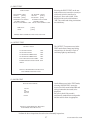
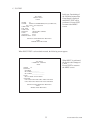
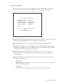
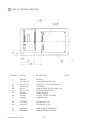
(3) INPUT TEST
INPUT TEST
1P WATER [OFF]
1P FOG
[OFF]
1P START [OFF]
2P WATER [OFF]
2P FOG
[OFF]
2P START [OFF]
1P SIGHT LOCATION
2P SIGHT LOCATION
[X:00H/Y:00H]
[X:00H/Y:00H]
1P OUT OF SCREEN OFF 2P OUT OF SCREEN OFF
SERVICE
TEST
Selecting the INPUT TEST on the test
mode menu screen causes the screen (on
which each switch is tested) to be
displayed. Press each switch. If the
display beside each switch indicates
"ON," the switch and wiring connections
are satisfactory.
[OFF]
[OFF]
PRESS TEST & SERVICE BUTTON TO EXIT
(4) OUTPUT TEST
The OUTPUT Test menu screen in the
TEST mode allows Lamps and wiring
connections to be checked. Check if
each lamp lights up satisfactorily.
OUTPUT TEST
1P START LAMP
2P START LAMP
OFF
OFF
1P NOZZLE VIBRATION
2P NOZZLE VIBRATION
OFF
OFF
LEFT REVOLVING LIGHT
OFF
RIGHT REVOLVING LIGHT OFF
>EXIT
SELECT WITH SERVICE BUTTON
AND PRESS TEST BUTTON
(5) SOUND TEST
On the Menu screen in the TEST mode,
selecting SOUND TEST causes the
screen (on which sound related BD and
wiring connections are tested) to be
displayed.
Be sure to check if the sound is
satisfactorily emitted from each speaker
and the sound volume is appropriate.
SOUND TEST MENU
AUTO
SE
VOICE
B.G.M.
>EXIT
SELECT WITH SERVICE BUTTON
AND PRESS TEST BUTTON
Perform the above inspections also at the time of monthly inspections.
27
www.seuservice.com
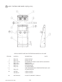
7. PRECAUTIONS TO BE HEEDED WHEN MOVING THE MACHINE
When moving the machine, be sure to pull out the plug from the power
supply. Moving the machine with the plug as is inserted can cause the power
cord to be damaged and could result in a fire and or electric shock.
When moving the machine on the floor, retract the Adjusters and ensure that
Casters make contact with the floor. During transportation, pay careful
attention so that Casters do not tread power cords and earth wires. Damaging
the power cords can cause an electric shock and or short circuit.
In places where step-like grade differences exist, be sure to separate the PTV,
PTV Cabinet, and the Control CABI. Inclining the PTV as is mounted on the
PTV Cabinet can cause the PTV to fall off from the Base and result in injury.
When lifting the cabinet, be sure to hold the catch portions or bottom part.
Lifting the cabinet by holding other portions can damage parts and installation
portions due to the empty weight of the cabinet, and cause personal injury.
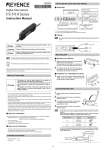
When moving the PTV, do not push it from the rear side. Push it from
sideways. Pushing the PTV from the rear side can have the PTV fall down,
causing personal injury etc. In case the floor has slanted surfaces or step-like
differences, be sure to move the machine by 2 or more persons.
When transporting the product in places
with steps or step-like differences in
grade, disassemble into each unit before
transporting.
Do not push PTV from the back. Pushing the PTV
from the back can cause the PTV to fall down. Push
it from the side.
GRIP
1234567890123456789012345678901212345678901234567890123456789012123456789012345678901234567890121234567890
1234567890123456789012345678901212345678901234567890123456789012123456789012345678901234567890121234567890
1234567890123456789012345678901212345678901234567890123456789012123456789012345678901234567890121234567890
1234567890123456789012345678901212345678901234567890123456789012123456789012345678901234567890121234567890
1234567890123456789012345678901212345678901234567890123456789012123456789012345678901234567890121234567890
On level surfaces, move the machine by causing
the Casters to make contact with the surfaces.
FIG. 7
www.seuservice.com
28
8. CONTENTS OF GAME
The following explanations apply to the case the product is functioning satisfactorily. Should
there be any moves different from the following contents, some sort of faults may have
occurred. Immediately look into the cause of the fault and eliminate the cause thereof to ensure
satisfactory operation.
HOW TO PLAY
REVOLVING LIGHT
The fluorescent lamp inside the Billboard
is always lit when the product is
energized. During Advertise, the game
images and the operating instruction are
outputted on the monitor. The Advertise
sounds during the Advertise Mode can be
set to ON or OFF in the TEST Mode.
BILLBOARD
PTV screen
1 Insert a coin(s).
2 When one play worth of coins is
inserted, the screen display
changes to "PRESS START
BUTTON" from "INSERT
COIN(S)." The number of credits
is displayed below the "PRESS
START BUTTON."
Up to 9 credits can be counted at a
time. Coins inserted after counting
9 credits are neither counted as
credits nor returned. However, the
coin meter functions.
START BUTTON
COIN Inlet
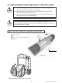
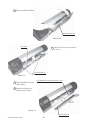
NOZZLE CONTROLLER
3 After one play worth of coins is inserted, the 2 Start
Buttons flash. Decide which side to play by pressing the
Start Button. Pressing the Start Button causes the credits
to be consumed. The Start Button of the side in play goes
off. The Start Button of the side not in play keeps
flashing if play worth credits still remain.
FIG. 8 a
4 Suspend Nozzle Controller's strap
from your shoulder and securely hold
the Controller. Turn the Nozzle
Controller to the screen, and the
Diffusion SIGHT appears on the
screen.
DRAINAGE Button
5 The Nozzle Controller is equipped
with the DRAINAGE Button (Red
Button) and the FOG STREAM SW
(Rotary Grip). Press the DRAINAGE
Button to spray water upon the
DRAINAGE SIGHT on the screen.
Pressing the DRAINAGE Button
causes the motor inside the Controller
to work, resulting in the Controller to
sway.
FOG STREAM SW
FIG. 8 b
29
www.seuservice.com
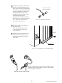
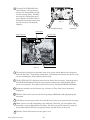
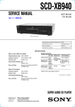
6 Twist the FOG STREAM SW for
water diffusion. The fog stream is
effective for distinguishing a nearby
fire and or flying sparks. Normally,
the actual fire extinguishing spot is
quite a distance from where water is
discharged from and the strong water
pressure can move or destroy the
obstacles.
FIG. 8 c
Standard Discharge
Fog Stream
TIME LIMIT
WATER GAUGE
1P
BONUS TIME
43
26.1
1P
DIFFUSION SIGHT
FIG. 8 d
7 The time limit is displayed on the upper center of the screen, and the Bonus time is displayed
below the time limit. The both time counts down. If the Bonus time remains after the fire is put
out, the remaining time will be added to the time limit.
8 The WATER GAUGE is displayed next to the time limit of the side in play. Keeping pressing
the DRAINAGE Button will drop the water pressure resulting in the flying distance and the
power to be weakened. The water pressure will recover by releasing the DRAINAGE Button.
9 Erroneous extinction can result in time loss, a decrease of Time Limit, due to unexpected
leaping fire.
10 When the Time Limit is near end, the Revolving lamps of Billboard left & right light up and
turn round.
11 If the Player succeeds to put out the fire within the Time Limit, he can proceed to the next stage.
12 When you move on with extinguishing a fire within the Time Limit, you will reach the final
scene where you must fight against a big flame. The final scene will be cleared if you put out
the big flame until the flame's power gauge becomes zero and all fires in the screen.
13 When the Time Limit becomes zero, the game is over.
www.seuservice.com
30
14 The game consists of 3 scenes. The time spent to clear and the score are displayed when each
scene is cleared.
15 If the Player's score is within the top 10 in rank upon clearing all 3 scenes, he can enter his
name. The entered name is displayed during ADVERTISE Mode.
16 After the Game Over, if one play worth or more credits remain, the screen displays the GAME
ENTRY Mode and the START Button flashes.
If no credits are left, the START Button remains unlit. Inserting a coin(s) within a certain time
period and pressing the START Button enables the player to continue play from that status.
KNACK OF PLAY
Put out the fire effectively by aiming at fire root!
The weak point of fire is the root. Spraying water on the object on fire directly enables you to
put out the fire effectively.
Use FOG STREAM to the close fire!
Fog stream is effective to fight against fire intercepting your sight.
Although power is not strong, the sprayed water expands wide and is capable of putting out fire
at a breath.
Use various methods for fire hard to put out!
Various obstacles exist in the place on fire. In order to put out fire beyond the obstacles, move
or destroy such obstacles in front of you with the pressure of water discharged. Also, to put out
fire hiding behind the objects, using fog stream is effective.
Predict wide expanding fire and put it out !
Fire spreads out unpredictably quick. Read the way a fire expands ahead of time and spray
water to check the spread of a fire. Put out fire around while checking the spread of a fire.
31
www.seuservice.com
9. EXPLANATION OF TEST AND DATA DISPLAY
By operating the switch unit, periodically perform the tests and data check. When installing the
machine initially or collecting cash, or when the machine does not function correctly, perform
checking in accordance with the explanations given in this section.
The following shows tests and modes that should be utilized as applicable.
SEGA HIKARU GAME BOARD is used for the product. The system of this game board
allows another game to be played by replacing the ROM Board Case mounted on the SEGA
HIKARU CASE. As such, the Test Mode of this system consists of the System Test Mode for
the system to execute SELF-TEST, COIN ASSIGNMENTS, etc. used in common for the
machines employing the SEGA HIKARU BOARD, and the Game Test Mode for the specific
product to execute Input/Output test for the operation equipment, difficulty setting, etc.
STOP
IMPORTANT!
The contents of settings changed in the TEST mode are stored when the test
mode is finished from EXIT in the menu mode. If the power is turned off
before the TEST mode is finished, the contents of setting change become
ineffective.
Executing "BACKUP DATA CLEAR" in the SYSTEM TEST MODE does
not clear the BOOKKEEPING data in the GAME TEST mode.
Entering the TEST mode clears fractional number of coins less than one credit
and BONUS ADDER data.
When performing the SYSTEM TEST Mode, do not turn the Nozzle
Controller to the screen. If the Nozzle Controller is turned to the screen, the
SYSTEM TEST Mode might be repeated due to reaction of the sensor. (The
same applies when turning on the DRAINAGE Button and FOG STREAM
SW.)
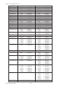
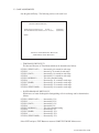
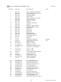
TABLE 9 EXPLANATION OF TEST MODE
ITEMS
DESCRIPTION
INSTALLATION OF
MACHINE
When the machine is installed, perform the following:
1. Check to see that each setting is as per standard setting made at the time of
shipment.
2. In the INPUT TEST mode, check such input devices as each SW, V.R., etc.
3. In the OUTPUT TEST mode, check such output devices as lamps, motors, etc.
4. In the SELF-TEST mode, check ICs on the IC Board.
REFERENCE
SECTIONS
9-2 F,G, 9-3 E
9-2 C, 9-3 B
9-3 C
9-2 B,J
MEMORY
Choose MEMORY TEST in the MENU mode to allow the MEMORY test to be
performed. In this test, PROGRAM RAMs, ROMs, and ICs on the IC Board are
checked.
PERIODIC
SERVICING
Periodically perform the following:
1. MEMORY TEST
2. Ascertain each setting.
3. In the INPUT TEST mode, test the CONTROL device
4. In the OUTPUT TEST mode, check such output devices as lamps, motors, etc.
CONTROL
SYSTEM
1. In the INPUT TEST mode, check such input devices as each SW, V.R., etc.
2. Adjust or replace each SW and VR.
3. If the problem can not be solved yet, check the CONTROL's moves.
9-2 C, 9-3 B
9-3 F, 10
MONITOR
In the MONITOR ADJUSTMENT mode,
check to see if the PROJECTOR adjustment is appropriately made.
9-2 E
12
IC BOARD
1. MEMORY TEST
2. In the SOUND TEST mode, check the sound related ROMs.
9-2 B,J
9-2 D, 9-3 D
DATA CHECK
Check such data as game play time and histogram to adjust the difficulty level, etc.
9-2 H, 9-3 G
www.seuservice.com
32
9-2 B,J
9-2 B,J
9-2 F,G, 9-3 E
9-2 C, 9-3 B
9-3 C
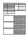
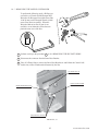
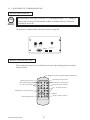
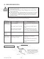
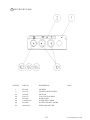
9 - 1 SWITCH UNIT AND COIN METER
Never touch places other than those specified. Touching places not specified can
cause electric shock and short circuit hazards.
STOP
IMPORTANT!
Adjust to the optimum sound volume by considering the environmental
requirements of the installation location.
If the COIN METER and the game board are electrically disconnected, game
play is not possible.
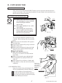
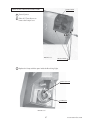
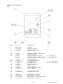
SWITCH UNIT
Open the coin chute door, and the switch unit
shown will appear.
The functioning of each SW is as follows:
SOUND VOLUME
TEST BUTTON
SERVICE BUTTON
FIG. 9. 1 a SWITCH UNIT
TEST BUTTON:
For the handling of the test button, refer to the following pages.
TEST
SERVICE BUTTON:
Gives credits without registering on the coin meter.
SERVICE
SOUND VOLUME:
Adjusts the sound volume of 2CH. Speaker.
SOUND VOLUME
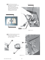
COIN METER
Open the Cashbox Door by using the key to have the Coin Meter appear
underneath the Cashbox.
COIN METER
FIG. 9. 1 b
33
www.seuservice.com
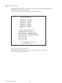
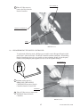
9 - 2 SYSTEM TEST MODE
A. SYSTEM TEST MODE MENU
Press TEST Button to enter the TEST MODE, and the following Menu screen will be displayed.
Press SERVICE Button to move the
arrow (>) to the desired item and
select with TEST Button.
SYSTEM MENU
X X X X X VERSION
RAM TEST
JVS TEST
SOUND TEST
C.R.T. TEST
SYSTEM ASSIGNMENTS
COIN ASSIGNMENTS
BOOKKEEPING
BACKUP DATA CLEAR
ROM TEST
CLOCK SETTING
B.F.F. TEST MENU
> EXIT
Bring the arrow to EXIT and press
TEST Button to return to the GAME
Mode.
SELECT WITH SERVICE BUTTON
AND
PRESS TEST BUTTON
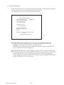
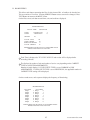
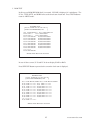
B. RAM TEST
This allows for checking the functioning of the RAM on the Game BD.
In this test, IC's are checked in every row. During the test, "CHECKING" is displayed at the
right-hand side of the screen. "BAD" is indicated for irregular RAMs, if any.
Upon finishing the test, "PRESS TEST BUTTON TO EXIT" is displayed on the lower center of
the monitor. Press TEST Button to return to the MENU screen.
RAM TEST
IC15 IC16 IC17S IC18S
IC22 IC23 IC24S IC25S
IC28 IC29S
IC41
IC42
IC44 IC45S IC46 IC47S
IC91S IC92S
IC98
GOOD
GOOD
GOOD
GOOD
GOOD
GOOD
GOOD
GOOD
PRESS TEST BUTTON TO EXIT
www.seuservice.com
34
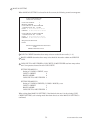
C. JVS TEST
JVS TEST
INPUT TEST
> EXIT
NODE
1/1
NAME
SEGA ENTERPRISES,LTD.;I/O BD JVS;
837-13551 ;Ver1.00;98/10
CMD VER
1.1
JVS VER
2.0
COM VER
1.0
SWITCH
2PLAYERS 13BITS
COIN
2SLOTS
ANALOG
8CH
DRIVER OUT 6CH
In this test, Functioning of
the I/O Board connected to
Game Board is displayed
and INPUT TEST can be
performed. Execute EXIT
to return to the MENU
screen.
SELECT WITH SERVICE BUTTON
AND
PRESS TEST BUTTON
When INPUT TEST is selected and executed, the following screen appears.
JVS TEST
> DISPLAY CONFIG
EXIT
NODE
1/1
SWITCH
SYSTEM _ _ _ _ _ _ _ _
PLAYER1 _ _ _ _ _ _ _ _ _ _ _ _ _
PLAYER2 _ _ _ _ _ _ _ _ _ _ _ _ _
COIN
SLOT1 0000 SLOT2 8000
ANALOG
CH1 6300 CH2 5A00 CH3 7D00 CH4 8100
CH5 1F00 CH6 1D00 CH7 1F00 CH8 2000
When INPUT is performed,
the Switch value changes to
1 from _.
Execute EXIT to return to
the MENU screen.
SELECT WITH SERVICE BUTTON
AND
PRESS TEST BUTTON
35
www.seuservice.com
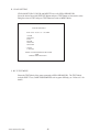
D. SOUND TEST
Sound Output can be performed and each Speaker can be checked.
Select the desired item and press TEST
Button, and sound is emitted from the
corresponding Speaker. Execute EXIT to
return to the MENU screen.
SOUND TEST
MAIN SPEAKER LEFT
MAIN SPEAKER RIGHT
> EXIT
SELECT WITH SERVICE BUTTON
AND
PRESS TEST BUTTON
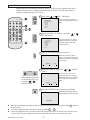
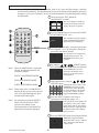
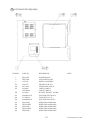
E. C.R.T. TEST
In this test, monitor adjustment can be performed. Periodically check to see if the monitor
adjustment is appropriate in this test. This test consists of 2 screens. Use SERVICE Button to
change the screen displayed. Press TEST Button to return to the MENU screen.
C.R.T. TEST PAGE#1
0
31
RED
GREEN
The first screen displays color bars. The
color adjustment can be checked. Each
of red, green, blue is the darkest at the
leftmost end, and becomes brighter
towards the right-hand end.
BLUE
WHITE
PRESS SERVICE BUTTON TO ANOTHER
PAGE
PRESS TEST BUTTON TO EXIT
12345678901234567890123456789
12345678901234567890123456789
12345678901234567890123456789
C.R.T. TEST PAGE#2
12345678901234567890123456789
12345678901234567890123456789
12345678901234567890123456789
12345678901234567890123456789
12345678901234567890123456789
12345678901234567890123456789
12345678901234567890123456789
12345678901234567890123456789
12345678901234567890123456789
12345678901234567890123456789
12345678901234567890123456789
12345678901234567890123456789
12345678901234567890123456789
12345678901234567890123456789
12345678901234567890123456789
12345678901234567890123456789
PRESS SERVICE BUTTON TO ANOTHER PAGE
12345678901234567890123456789
PRESS TEST BUTTON TO EXIT
12345678901234567890123456789
www.seuservice.com
36
The second screen displays crosshatches.
In this page, monitor size and deviation
can be checked.
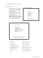
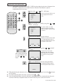
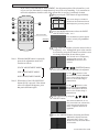
F. SYSTEM ASSIGNMENTS
The settings of cabinet and board can be changed. Set each item suitable to the connected
cabinet. Use the setting as is the time of shipment except for ADVERTISE SOUND.
SYSTEM ASSIGNMENTS
CABINET TYPE
2PLAYERS
ADVERTISE SOUND ON
MONITOR TYPE
HORIZONTAL
DISPLAY MODE
AUTOSCAN
SERVICE TYPE
COMMON
> EXIT
SELECT WITH SERVICE BUTTON
AND
PRESS TEST BUTTON
CABINET TYPE specifies Control Panel and number of Coin Chute. The number of Player
displayed in BOOKKEEPING varies in accordance with the value here.
ADVERTISE SOUND is used for settings of emitting sound during ADVERTISE.
MONITOR TYPE sets the on-screen display to the positional direction of monitor (HORIZONTAL or VERTICAL). If set to VERTICAL, the on-screen display for the test mode is
vertically positioned in accordance with the setting.
DISPLAY MODE sets the monitor's display frequency. In this mode, if other than
AUTOSCAN is selected and EXIT is executed, the display frequency is changed to the
selected setting.
SERVICE TYPE sets the functioning of when the Service Button is pressed, in case that
several Service Buttons exist.
• INDIVIDUAL
By pressing Service Button, Service credit can be obtained for the Player corresponding
to the Service Button pressed.
• COMMON
By pressing any Service Button, Service credit can be obtained for all Players.
37
www.seuservice.com
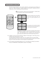
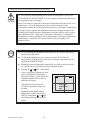
G. COIN ASSIGNMENTS
In this mode, the setting of incremental credit increase as against con insertion can be changed.
This test consists of 3 screens, and the following is the first screen.
The setting done in the first screen will be stored when exited.
COIN ASSIGNMENTS
COIN CHUTE TYPE
COMMON
COIN/CREDI SETTING
#1
COIN CHUTE #1
1COIN 1CREDIT
COIN CHUTE #2
1COIN 1CREDIT
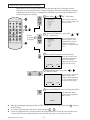
MANUAL SETTING
SEQUENCE SETTING
> EXIT
SELECT WITH SERVICE BUTTON
AND
PRESS TEST BUTTON
COIN CHUTE TYPE sets whether Coin Chute is used in common by all players or
separately allocated to each player in case 2 or more Coin Chutes are incorporated.
COMMON: This setting is for common use by plural players.
INDIVIDUAL: As each player uses an independent coin chute, setting to INDIVIDUAL
causes COIN CHUTE #2 to be disappeared.
COIN/CREDT SETTING is set when using one of the existing 26 settings or FREE PLAY.
The selected coin rates in the COIN/CREDIT SETTING are displayed below COIN CHUTE
#1 and COIN CHUTE #2. If you wish to set a coin rate rather than to select from the
existing setting, select MANUAL SETTING. The display next to COIN/CREDIT SETTING
indicates "MANUAL", not "#n" in this case.
www.seuservice.com
38
MANUAL SETTING
When MANUAL SETTING is selected in the first screen, the following second screen appears.
COIN ASSIGNMENTS
MANUAL SETTING
COIN TO CREDIT
1
BONUS ADDER
0
COIN CHUTE #1 MULTIPLIER
1 COINCOUNT AS 1COIN
COIN 1 2 3 4 5 6 7 8 9
CREDIT 1 2 3 4 5 6 7 8 9
COIN CHUTE #2 MULTIPLIER
1 COINCOUNT AS 1COIN
COIN 1 2 3 4 5 6 7 8 9
CREDIT 1 2 3 4 5 6 7 8 9
SEQUENCE SETTING
> EXIT
SELECT WITH SERVICE BUTTON
AND
PRESS TEST BUTTON
COIN TO CREDIT determines how many coins are needed for one credit. (1 ~ 9)
BONUS ADDER determines how many coins should be inserted to obtain one SERVICE
COIN.
COIN CHUTE #1 MULTIPLIER, COIN CHUTE #2 MULTIPLIER sets how many tokens
one Coin represents inserted in each COIN CHUTE.
SETTING EXAMPLE 1)
Setting of 2 COINS 1 CREDIT, set to:
COIN TO CREDIT
:2
BONUS ADDER
:0
COIN CHUTE #1 MULTIPLIER :1
SETTING EXAMPLE 2)
Setting of 5 COINS 6 CREDITS (5 COINS 1 BONUS), set to
COIN TO CREDIT
:1
BONUS ADDER
:5
COIN CHUTE #1 MULTIPLIER :1
When exiting from MANUAL SETTING, if the identical coin rate is in the existing COIN/
CREDIT SETTING, such existing mode other than what is set in the MANUAL SETTING is
confirmed.
39
www.seuservice.com
TABLE 1 COIN/CREDIT SETTING
NAME OF SETTING
SETTING
SETTING
SETTING
SETTING
SETTING
SETTING
SETTING
SETTING
SETTING
SETTING
SETTING
SETTING
SETTING
SETTING
SETTING
#1
#2
#3
#4
#5
#6
#7
#8
#9
#10
#11
#12
#13
#14
#15
FUNCTIONING OF COIN CHUTE #1
1
1
1
1
1
1
1
1
1
1
1
2
1
1
1
2
1
COIN
COIN
COIN
COIN
COIN
COIN
COIN
COIN
COIN
COIN
COIN
COINS
COIN
COIN
COIN
COINS
COIN
1
2
3
4
5
2
5
3
4
5
6
1
1
2
1
3
3
CREDIT
CREDITS
CREDITS
CREDITS
CREDITS
CREDITS
CREDITS
CREDITS
CREDITS
CREDITS
CREDITS
CREDIT
CREDIT
CREDITS
CREDIT
CREDITS
CREDITS
SETTING #20
3
4
1
2
3
4
1
COINS
COINS
COIN
COINS
COINS
COINS
COIN
1
1
1
2
3
5
5
CREDIT
CREDIT
CREDIT
CREDITS
CREDITS
CREDITS
CREDITS
SETTING #21
SETTING #22
5 COINS
1 COIN
1 CREDIT
2 CREDITS
SETTING #23
2
4
5
1
COINS
COINS
COINS
COIN
1
2
3
3
CREDIT
CREDITS
CREDITS
CREDITS
1
2
3
4
5
1
COIN
COINS
COINS
COINS
COINS
COIN
1
2
3
4
6
6
CREDIT
CREDITS
CREDITS
CREDITS
CREDITS
CREDITS
SETTING #16
SETTING #17
SETTING #18
SETTING #19
SETTING #24
SETTING #25
SETTING #26
SETTING #27
www.seuservice.com
FREE PLAY
40
FUNCTIONING OF COIN CHUTE #2
1
1
1
1
1
1
1
1
1
1
1
2
2
2
1
2
1
2
3
4
1
2
3
4
1
2
3
4
5
3
5
2
4
5
2
4
5
1
2
3
4
5
1
2
3
4
5
COIN
COIN
COIN
COIN
COIN
COIN
COIN
COIN
COIN
COIN
COIN
COINS
COINS
COINS
COIN
COINS
COIN
COINS
COINS
COINS
COIN
COINS
COINS
COINS
COIN
COINS
COINS
COINS
COINS
COINS
COINS
COINS
COINS
COINS
COINS
COINS
COINS
COIN
COINS
COINS
COINS
COINS
COIN
COINS
COINS
COINS
COINS
FREE
1 CREDIT
1 CREDIT
1 CREDIT
1 CREDIT
1 CREDIT
2 CREDITS
2 CREDITS
3 CREDITS
4 CREDITS
5 CREDITS
6 CREDITS
1 CREDIT
1 CREDIT
1 CREDIT
1 CREDIT
3 CREDITS
1 CREDIT
3 CREDITS
1 CREDIT
1 CREDIT
1 CREDIT
2 CREDITS
3 CREDITS
5 CREDITS
1 CREDIT
2 CREDITS
3 CREDITS
5 CREDITS
1 CREDIT
1 CREDIT
2 CREDITS
1 CREDIT
2 CREDITS
3 CREDITS
1 CREDIT
2 CREDITS
3 CREDITS
1 CREDIT
2 CREDITS
3 CREDITS
4 CREDITS
6 CREDITS
1 CREDIT
2 CREDITS
3 CREDITS
4 CREDITS
6 CREDITS
PLAY
Table 2: COIN/CREDIT SETTING (COIN CHUTE INDIVIDUAL TYPE)
NAME OF SETTING
SETTING #1
SETTING #2
SETTING #3
SETTING #4
SETTING #5
SETTING #11
SETTING #12
SETTING #15
SETTING #17
SETTING #18
SETTING #19
EACH SEAT'S COIN CHUTE
1 COIN
1 CREDIT
1 COIN
2 CREDITS
1 COIN
3 CREDITS
1 COIN
4 CREDITS
1 COIN
5 CREDITS
1 COIN
6 CREDITS
2 COINS 1 CREDIT
1 COIN
1 CREDIT
2 COINS 3 CREDITS
3 COINS 1 CREDIT
4 COINS 1 CREDIT
1 COIN
1 CREDIT
2 COINS 2 CREDITS
3 COINS 3 CREDITS
4 COINS 5 CREDITS
NAME OF SETTING EACH SEAT'S COIN CHUTE
SETTING #21
5 COINS 1 CREDIT
SETTING #23
2 COINS 1 CREDIT
4 COINS 2 CREDITS
5 COINS 3 CREDITS
SETTING #25
1 COIN
1 CREDIT
2 COINS 2 CREDITS
3 COINS 3 CREDITS
4 COINS 4 CREDITS
5 COINS 6 CREDITS
SETTING #27
FREE PLAY
Table 3: MANUAL SETTING
C O I N TO C R E D I T
1
2
3
4
5
6
7
8
9
BONUS ADDER
NO BONUS
2 COINS GIVE
3 COINS GIVE
4 COINS GIVE
5 COINS GIVE
6 COINS GIVE
7 COINS GIVE
8 COINS GIVE
9 COINS GIVE
COIN
CHUTE (#1/# 2)
MULTIPLIER
1
1
1
1
1
1
1
1
1
41
COIN
COINS
COINS
COINS
COINS
COINS
COINS
COINS
COINS
1
2
3
4
5
6
7
8
9
CREDIT
CREDIT
CREDIT
CREDIT
CREDIT
CREDIT
CREDIT
CREDIT
CREDIT
ADDER
1 EXTRA COIN
1 EXTRA COIN
1 EXTRA COIN
1 EXTRA COIN
1 EXTRA COIN
1 EXTRA COIN
1 EXTRA COIN
1 EXTRA COIN
COIN COUNTS AS
COIN COUNTS AS
COIN COUNTS AS
COIN COUNTS AS
COIN COUNTS AS
COIN COUNTS AS
COIN COUNTS AS
COIN COUNTS AS
COIN COUNTS AS
1
2
3
4
5
6
7
8
9
COINS
COINS
COINS
COINS
COINS
COINS
COINS
COINS
COINS
www.seuservice.com
SEQUENCE SETTING
When SEQUENCE SETTING is selected in either first or second screen, the SEQUENCE
SETTING Mode (the third screen) appears.
In this mode, number of credits required for starting game can be set.
COIN ASSIGNMENTS
SEQUENCE SETTING
SEQUENCE1
SEQUENCE2
SEQUENCE3
SEQUENCE4
SEQUENCE5
SEQUENCE6
SEQUENCE7
SEQUENCE8
> EXIT
2CREDITS
2CREDITS
1CREDIT
1CREDIT
0CREDIT
0CREDIT
0CREDIT
0CREDIT
[ B.F.F. GAME X X X X X X X X]
[ SEGA ENTERPRISES,LTD.
]
DESCRIPTION OF SEQUENCE
SEQ1 CREDIT TO 1 PLAYER START
SEQ2 CREDIT TO 2 PLAYERS START
SEQ3 CREDIT TO 1 PLAYER CONTINUE
SEQ4 CREDIT TO 2 PLAYERS CONTINUE
SEQ5 NOT USED
SEQ6 NOT USED
SEQ7 NOT USED
SEQ8 NOT USED
SELECT WITH SERVICE BUTTON
AND
PRESS TEST BUTTON
Each sequence can be set between 1 ~ 5.
In this example, setting of Sequence 1 is for 1 Player with 1 credit to start game.
Select EXIT to return to the first screen.
www.seuservice.com
42
H. BOOKKEEPING
This allows such data as operating time/No. of coins inserted/ No. of credits to be checked, etc.
This test consists of 2 screens. Pressing SERVICE Button causes screen to be changed. Press
TEST Button to return to the MENU screen.
On the first screen, such data as total time, coin, and credit are displayed.
BOOKKEEPING
TOTAL TIME
COIN1
COIN2
55H27M13S
16 SERVICE1
4 SERVICE2
CREDIT
5
0
10
TOTAL COIN
COIN CREDIT
SERVICE CREDIT
TOTAL CREDIT
20
10
5
15
PRESS SERVICE BUTTON TO ANOTHER PAGE
PRESS TEST BUTTON TO EXIT
Total Time is displayed as "X X H X X M X X S" and no date will be displayed after
exceeding 24 hours.
The displays for number of coin and number of service vary depending on the CABINET
TYPE set in SYSTEM ASSIGNMENTS.
Number of credit displays 1 if COIN CHUTE TYPE is set to COMMON in COIN
ASSIGNMENTS. If COIN CHUTE TYPE is set to INDIVIDUAL, the applicable number in
CABINET TYPE setting will be displayed.
On the second screen, each sequence displays the frequency of functioning.
BOOKKEEPING
PLAYER1
SEQ1
SEQ2
SEQ3
SEQ4
SEQ5
SEQ6
SEQ7
SEQ8
1
0
1
0
0
0
0
0
PLAYER2
SEQ1
0
SEQ2
1
SEQ3
0
SEQ4
1
SEQ5
0
SEQ6
0
SEQ7
0
SEQ8
0
PRESS SERVICE BUTTON TO ANOTHER PAGE
PRESS TEST BUTTON TO EXIT
43
www.seuservice.com
I. BACKUP RAM CLEAR
Clears contents of BOOKKEEPING, operating time, coin/credit data, number of games played,
etc.
BACKUP RAM CLEAR
YES (CLEAR)
> NO (CANCEL)
SELECT WITH SERVICE BUTTON
AND
PRESS TEST BUTTON
Selecting YES clears the aforementioned data. Select NO and press TEST Button to have the
MENU mode return without clearing data.
Note that this does not affect the data of BOOKKEEPING in GAME TEST Mode. To clear the
contents of BOOKKEEPING in GAME TEST Mode, enter into GAME TEST Mode and
execute BACKUP DATA CLEAR.
www.seuservice.com
44
J. ROM TEST
In this test, on-ROM-BD ROM check is executed. If GOOD is displayed, it is satisfactory. The
IC No., TYPE, BYTE, and WORD refers to the check sum of each unit. Press TEST Button to
return to MENU mode.
ROMBD TEST
[ B.F.F. GAME X X X X X X X X ]
[ SEGA ENTERPRISES,LTD.
]
NO. TYPE RESULT NO. TYPE RESULT
IC29 16M ---IC51 64M GOOD
IC30 16M ---IC52 64M GOOD
IC31 16M GOOD
IC53S 64M GOOD
IC32 16M GOOD
IC54S 64M GOOD
IC33 16M GOOD
IC55S 64M GOOD
IC34 16M GOOD
IC56S 64M GOOD
IC37 64M GOOD
IC57S 64M GOOD
IC38 64M GOOD
IC58S 64M GOOD
IC39 64M GOOD
IC59S 64M GOOD
IC40 64M GOOD
IC60S 64M GOOD
•••• ••• ••••
IC50 64M GOOD
PRESS TEST BUTTON TO EXIT
In case of above screen, IC 29 and IC 30 do not display GOOD or BAD.
Press SERVICE Button to proceed to the screen the check sum is displayed.
ROMBD TEST
[ B.F.F. GAME X X X X X X X X]
[ SEGA ENTERPRISES,LTD.
]
NO. TYPE BYTE WORD NO. TYPE BYTE WORD
IC29 16M **** **** IC51 64M **** ****
IC30 16M **** **** IC52 64M **** ****
IC31 16M **** **** IC53S 64M **** ****
IC32 16M **** **** IC54S 64M **** ****
IC33 16M **** **** IC55S 64M **** ****
IC34 16M **** **** IC56S 64M **** ****
IC37 64M **** **** IC57S 64M **** ****
IC38 64M **** **** IC58S 64M **** ****
IC39 64M **** **** IC59S 64M **** ****
IC40 64M **** **** IC60S 64M **** ****
•••• ••• •••• ••••
IC50 64M **** ****
PRESS TEST BUTTON TO EXIT
45
www.seuservice.com
K. CLOCK SETTING
YEAR, MONTH, DAY, HOUR, and MINUTE are set for SEGA HIKARU BD.
Select the desired item with SERVICE Button and press TEST Button to increase the value.
Bring the arrow to EXIT and press TEST Button to return to MENU Mode.
CLOCK SETTING
1999 07/07 07:07 07 07 WED
YEAR
MONTH
DAY
HOUR
MINUTE
SECOND
-> EXIT
CANCEL
SELECT WITH SERVICE BUTTON
AND
PRESS TEST BUTTON
L. B.F.F. TEST MENU
Enters the TEST Mode of the game connected to SEGA HIKARU BD. The TEST Mode
includes INPUT Test, GAME ASSIGNMENTS such as game difficulty, etc. Refer to 9-3 for
details.
www.seuservice.com
46
9 - 3 GAME TEST MODE (B.F.F. TEST MODE)
A. MENU SCREEN
SYSTEM TEST MENU screen
Select and execute B.F.F. TEST MENU
in SYSTEM TEST MENU screen to
have the Menu screen of GAME TEST
MODE displayed.
In the GAME TEST MODE, various
settings for "BRAVE FIRE FIGHTERS"
can be performed.
Operation method is same as in the
SYSTEM TEST MODE. By pressing
SERVICE Button, move the arrow to the
desired item and press TEST Button to
execute/change the selected item.
SYSTEM MENU
RAM TEST
JVS TEST
SOUND TEST
C.R.T. TEST
SYSTEM ASSIGNMENTS
COIN ASSIGNMENTS
BOOKKEEPING
BACKUP DATA CLEAR
ROM TEST
CLOCK SETTING
ŮB.F.F. TEST MENU
EXIT
SELECT WITH SERVICE BUTTON
AND PRESS TEST BUTTON
B.F.F TEST MENU
INPUT TEST
OUTPUT TEST
SOUND TEST
GAME ASSIGNMENTS
NOZZLE SENSOR SETTING
BOOKKEEPING
BACKUP DATA CLEAR
ŮEXIT
SELECT WITH SERVICE BUTTON
AND PRESS TEST BUTTON
• INPUT TEST
: Performs INPUT TEST
• OUTPUT TEST
: Performs OUTPUT TEST
• SOUND TEST
: Performs SOUND TEST
• GAME ASSIGNMENTS
: Set the game difficulty.
• NOZZLE SENSOR SETTING
: Sets the Nozzle Sensor reaction.
• BOOKKEEPING
: Displays various data.
• BACKUP DATA CLEAR
: Clears BOOKKEEPING data, etc.
• EXIT
: Exit from the TEST Mode.
47
www.seuservice.com
B. INPUT TEST
Allows the status of each Controller, Button, Switch, etc. to be checked. Periodically check the
status in this mode.
INPUT TEST
1P WATER [OFF]
1P FOG [OFF]
1P START [OFF]
2P WATER [OFF]
2P FOG [OFF]
2P START [OFF]
1P SIGHT LOCATION
2P SIGHT LOCATION
[X:00H/Y:00H]
[X:00H/Y:00H]
1P OUT OF SCREEN OFF 2P OUT OF SCREEN OFF
SERVICE
TEST
[OFF]
[OFF]
PRESS TEST & SERVICE BUTTON TO EXIT
• 1P (2P) WATER
: DRAINAGE BUTTON
• 1P (2P) FOG
: FOG STREAM SWITCH
• 1P (2P) START
: START BUTTON
• 1P (2P) SIGHT LOCATION
: VALUE OF NOZZLE'S SIGHT LOCATION
• 1P (2P) OUT OF SCREEN
: JUDGEMENT FOR OUT OF SCREEN
• SERVICE
: SERVICE BUTTON
• TEST
: TEST BUTTON
Press each Button, and the display changes to ON from OFF.
The volume value when the Nozzle is turned to the screen is displayed in hexadecimal numerals
within the range of 00H ~ FFH as corresponding to X and Y coordinate values below "1P (2P)
SIGHT LOCATION." "OUT OF SCREEN" goes ON as the sensor can not react when the
Nozzle is turned out of screen.
www.seuservice.com
48
C. OUTPUT TEST
Allows the status of each Lamp, Motor, etc. to be checked. Periodically check the status in this
mode.
OUTPUT TEST
1P START LAMP
2P START LAMP
OFF
OFF
1P NOZZLE VIBRATION
2P NOZZLE VIBRATION
OFF
OFF
LEFT REVOLVING LIGHT
RIGHT REVOLVING LIGHT
OFF
OFF
>EXIT
SELECT WITH SERVICE BUTTON
AND PRESS TEST BUTTON
• START LAMP
: START Buttons' Lamps light up.
• NOZZLE VIBRATION
: Vibration of NOZZLE CONTROLLER.
• REVOLVING LIGHT
: REVOLVING LIGHT lights up.
Bring the arrow to each item and press TEST Button. The right-hand side "ON" & "OFF"
display automatically alternates and the lamp lights up and goes off in consistency with the
display of "ON" and "OFF."
49
www.seuservice.com
D. SOUND TEST
Selecting SOUND TEST in the MENU Mode displays the following and allows sounds used in
game (B.G.M./VOICE/EFFECT) to be checked. Periodically check the status of the sound
related BD., IC, and Speaker in this Mode.
SOUND TEST MENU
AUTO
SE
VOICE
B.G.M.
• AUTO
: Sound Effects >VOICE
>B.G.M. are emitted
sequentially in order.
• SE
: Sound Effects are
emitted.
• VOICE
: Voice during game is
emitted.
• B.G.M.
: Background music
during game is emitted.
>EXIT
•
EXIT
SELECT WITH SERVICE BUTTON
AND PRESS TEST BUTTON
Select the item with SERVICE Button
and press TEST Button.
Sounds used in the game such as SE,
VOICE, B.G.M. are emitted in each test
item.
In AUTO, SE, VOICE, and B.G.M.
respectively, every time SERVICE
Button is pressed, the next sound within
No. 0 ~ X is emitted. (The screen shown
left is in case of SE)
Press TEST Button to return to the
SOUND TEST MENU screen.
SOUND TEST
SE
No.
: Finishes Sound Test.
0
SELECT WITH SERVICE BUTTON
PRESS TEST BUTTON TO EXIT
In case of AUTO, pressing SERVICE Button once causes sounds to be emitted continuously
from No. 0. Press SERVICE Button to stop emitting sound for a while, and press SERVICE
Button again to restart emitting sound from the current status.
www.seuservice.com
50
E. GAME ASSIGNMENTS
Sets the game difficulty. The following can be set for each level.
GAME ASSIGNMENTS
TIME BONUS DIFFICULTY
LEVEL 5
WATER DRAINAGE DIFFICULTY LEVEL 5
(NORMAL)
(NORMAL)
>EXIT
SELECT WITH SERVICE BUTTON
AND PRESS TEST BUTTON
• TIME BONUS DIFFICULTY
The Increase/Decrease of Time Bonus added can be determined as follows.
LEVEL1 (VERY EASY) ......... Increased by 64 seconds in each stage
LEVEL2 ................................... Increase by 32 seconds in each stage.
LEVEL3 (EASY) ..................... Increased by 16 seconds in each stage.
LEVEL4 ................................... Increased by 11 seconds in each stage.
LEVEL5 (NORMAL) .............. This is the standard setting.
LEVEL6 ................................... Decreased by 11 seconds in each stage.
LEVEL7 (HARD) .................... Decreased by 16 seconds in each stage.
LEVEL8 ................................... Decreased by 32 seconds in each stage.
LEVEL9 (VERY HARD) ......... Decreased by 64 seconds in each stage.
• WATER DRAINAGE DIFFICULTY
Effectiveness of water discharged in distinguishing a fire in each stage can be determined as
follows.
LEVEL1 (VERY EASY) ......... Increased by 35%
LEVEL2 ................................... Increased by 25%
LEVEL3 (EASY) ..................... Increased by 15%
LEVEL4 ................................... Increased by 5%
LEVEL5 (NORMAL) .............. This is the standard setting.
LEVEL6 ................................... Decreased by 5%
LEVEL7 (HARD) .................... Decreased by 15%
LEVEL8 ................................... Decreased by 25%
LEVEL9 (VERY HARD) ......... Decreased by 35%
Select EXIT and press TEST Button to return to GAME TEST MODE Menu screen.
51
www.seuservice.com
F. NOZZLE SENSOR
Sets the Nozzle Controller's reaction
range. Choose the item from among the
following.
NOZZLE SENSOR SETTING
1P NOZZLE CHECK
2P NOZZLE CHECK
•1P NOZZLE CHECK
•2P NOZZLE CHECK
1P NOZZLE SETTING
2P NOZZLE SETTING
•1P NOZZLE SETTING
•2P NOZZLE SETTING
1P DEFAULT SETTING
2P DEFAULT SETTING
>EXIT
•1P DEFAULT SETTING
•2P DEFAULT SETTING
SELECT WITH SERVICE BUTTON
AND PRESS TEST BUTTON
Select EXIT and press TEST Button to return to GAME TEST MODE Menu screen.
1P(2P) NOZZLE CHECK
The Nozzle Controller can be checked by
moving the SIGHT in the current moving
range.
Displays the actual coordinate value of
the SIGHT. When the SIGHT goes out
of screen, "OUT OF SCREEN" will be
displayed.
If everything is satisfactory, press TEST
Button to exit. If problem is found with
the current moving range area, return to
NOZZLE SENSOR SETTING screen
and perform setting in each setting
screen.
1P NOZZLE CHECK
1P SIGHT LOCATION
[X:000.000/Y:000.000]
SIGHT
PRESS TEST BUTTON TO EXIT
www.seuservice.com
52
Aim at the UPPER-LEFT corner of the screen
1P(2P) NOZZLE SETTING
Sets t he SENSOR's reaction range area
by marking 4 corners and the center of
the screen.
Decide with 1P START or 1P WATER BUTTON
1 Aim at UPPER-LEFT corner of the
1P NOZZLE SETTING
screen
2 Aim at UPPER-RIGHT corner of the
screen
3 Aim at LOWER-RIGHT corner of the
screen
4 Aim at LOWER-LEFT corner of the
screen
5 Aim at CENTER of the screen
PRESS TEST BUTTON TO EXIT
Perform Marking for setting the screen range sequentially in order of 1 Upper Left >
2 Upper Right > 3 Lower Right > 4 Lower Left > 5 Center of the screen.
Turn the SIGHT and mark with START Button or DRAINAGE Button.
1P NOZZLE SETTING
Aim at the CENTER of the screen
Decide with 1P START or 1P WATER BUTTON
Upon finishing marking 1 through 4 ,
the screen range's diagonal extended
from the 4 corners is displayed.
Afterward, 5 Center is marked and then
the screen proceeds to 1P(2P) NOZZLE
CHECK after all 5 markings are
completed.
PRESS TEST BUTTON TO EXIT
53
www.seuservice.com
1P NOZZLE CHECK
The Nozzle Controller can be checked by
moving the SIGHT freely within the
moving range determined in the 1P (2P)
NOZZLE SETTING.
Displays the actual coordinate value of
the SIGHT. When the SIGHT goes out
of screen, "OUT OF SCREEN" will be
displayed.
Select YES (SAVE) to save the setting
data, and the setting is complete. Select
NO (CANCEL) to return to 1P (2P)
NOZZLE SETTING and set the marking
again from 1 Upper Left.
1P SIGHT LOCATION
[X:000.000/Y:000.000]
YES(SAVE)
>NO (CANCEL)
SELECT WITH SERVICE BUTTON
AND PRESS TEST BUTTON
1P(2P) DEFAULT SETTING
The pre-programmed default value can
be set as the Nozzle Controller's sensor
range. Check to see by moving the
SIGHT. If the default value is
satisfactory, select YES (Save) to save
the default value setting. If the SIGHT
does not move within the correct range,
perform the setting individually in the 1P
(2P) NOZZLE SETTING.
1P DEFAULT SETTING
1P SIGHT LOCATION
[X:000.000/Y:000.000]
YESÅiSAVEÅj
>NO (CANCEL)
SELECT WITH SERVICE BUTTON
AND PRESS TEST BUTTON
www.seuservice.com
54
G. BOOKKEEPING
BOOKKEEPING
BOOKKEEPING (PAGE1/2)
Displays the data of operating status with
respect to game play time.
Page 1/2 displays the detailed game play
time.
PAGE 1/2
TIME REPORT
TOTAL TIME
00D 00H 00M 00S
PLAY TIME
00D 00H 00M 00S
NUMBER OF GAMES
00
AVERAGE PLAY TIME
LONGEST PLAY TIME
SHORTEST PLAY TIME
0M 00S
0M 00S
0M 00S
PRESS TEST BUTTON TO CONTINUE
• TOTAL TIME
• PLAY TIME
• NUMBER OF GAMES
: The total energized time.
: Total play time.
: Total number of plays.
• AVERAGE PLAY TIME
• LONGEST PLAY TIME
• SHORTEST PLAY TIME
Press TEST Button to proceed to the next screen.
BOOKKEEPING
BOOKKEEPING (PAGE2/2)
Displays the data of operating status with
respect to game play time.
Page 2/2 displays the Histogram of
Number of Play as against Play Time.
By-playtime play frequency bookkeeping
is displayed in increments of 30 seconds
from 0M00S to 9M59s. Playtime in
excess of 10 minutes is saved all in the
category of OVER 10M00S.
PAGE 2/2
TIME HISTOGRAM
0M 00S ~ 0M 29S
0M 30S ~ 0M 59S
1M 00S ~ 1M 29S
1M 30S ~ 1M 59S
2M 00S ~ 2M 29S
2M 30S ~ 2M 59S
3M 00S ~ 3M 29S
3M 30S ~ 3M 59S
0
0
0
0
0
0
0
0
9M 00S ~ 9M 29S
9M 30S ~ 9M 59S
OVER 10M 00S
0
0
0
PRESS TEST BUTTON TO EXIT
Press TEST Button to return to the Menu screen of GAME TEST Mode.
55
www.seuservice.com
H. BACKUP DATA CLEAR
Clears BOOKKEEPING data and RANKING data.
When clearing, bring the arrow to "YES" and press TEST Button. Move the arrow to "NO" and
press TEST Button when not clearing. The screen automatically returns to the Menu screen of
GAME TEST Mode.
BACKUP DATA CLEAR
YES (CLEAR)
>NO (CANCEL)
SELECT WITH SERVICE BUTTON
AND PRESS TEST BUTTON
www.seuservice.com
56
10. NOZZLE CONTROLLER
Before starting to work, ensure that the Power SW is OFF. Failure to observe
this can cause electric shock or short circuit.
Use care so as not to damage wirings. Damaged wiring can cause electric
shock or short circuit.
Do not touch undesignated places. Touching places not designated can cause
electric shock or short circuit.
This work should be performed by the Location's Maintenance Man or
Serviceman. Performing work by non-technical personnel can cause electric
shock hazard.
Do not perform work other than those specified in this Manual in order to
prevent accidents during performing work and operation after performing
work. Performing work not specified in this Manual may require special
training for this product. If performing work other than those stated in this
manual is required for repair, contact the offices herein stated in this manual
or where you purchased the product from and ask for repair or inquire how to
repair.
When handling the parts inside the Nozzle Controller, use care so as not to cause
damaging, missing, or deformation of parts. For example, applying excessive
load in an attempt to connect the connector to the wrong direction can damage
wiring or soldering on the PCB resulting in insufficient connection, etc.
Since Nozzle Controller is composed of many parts, replacement of each part is not separately
explained in this manual. However, this manual explains how to disassemble Nozzle
Controller. When a part replacement is necessary, disassemble Nozzle Controller by referring
to this manual up to the point in which the part replacement is explained. In order to
disassemble Nozzle Controller, first remove Security Wire and then take off Nozzle Controller
from the Cabinet.
Security Wire can be replaced in the manner as Security Wire is removed. When Nozzle
Controller is removed from the cabinet, the Hose and Nozzle Controller, respectively, can be
replaced.
10 - 1 REMOVING THE SECURITY WIRE
The Security Wire is an important accident preventative part. If damaged,
immediately replace the Security Wire. Using the Wire as is damaged will cause
personal injury.
To perform following work, a Phillips type screwdriver and a wrench for M3 hexagon Nut are
necessary.
1 Turn off power for safety.
57
www.seuservice.com
1 Take off 4 Truss screws and remove the removing side of Panel Lid from the Control Cabinet.
PANEL LID
TRUSS SCREW (6)
M4 X 12
PHOTO 10. 1 a
2 Take off a screw from the inside where Panel Lid is removed to take off a Shoulder pin.
SHOULDER PIN
SCREW (1)
M4 X 6,w/spring washer,
flat washer used.
PHOTO 10. 1 b
www.seuservice.com
58
4 Take off 4 Flat Head screws
from the nose of Nozzle
Controller and remove the
Security Plate.
SECURITY PLATE
FRONT VIEW
FLAT HEAD SCREW (4)
M3 X 10
PHOTO 10. 1 c
5 Take off 2 Flange Nuts and remove the Security Hook from the Security Plate.
SECURITY HOOK
PHOTO 10. 1 d Security Plate (Front)
SECURITY WIRE
FRQ-2708
FLANGE NUT (2)
M3
PHOTO 10. 1 e Security Plate (Reverse)
59
www.seuservice.com
10 - 2 REMOVING THE ASSY SENSOR
1 Turn off power for safety.
2 Perform work up to the procedure áC in 10-1 REMOVING THE SECURITY WIRE.
(PHOTO 10. 1 c)
ASSY SENSOR
3 Take out the ASSY SENSOR from
the Nozzle Controller. At this
time, use care so as not to damage
NOZZLE CONTROLLER
the wiring and the joint portion.
4 Disconnect the wiring connector
from the ASSY SENSOR board.
PHOTO 10. 2 a
5 Take off 2 screws to disassemble
the ASSY SENSOR.
SCREW (2)
M3 X 6,w/flat & spring washers
PHOTO 10. 2 b
PHOTO 10. 2 c
www.seuservice.com
60
10 - 3 REMOVING THE NOZZLE CONTROLLER
To perform the following work, a Philips type
screwdriver, a Wrench for M4 Hexagon Nut,
Wrenches for Hexagon Nut (width across flats
14 & 50 mm), and a Hexagon Wrench (width
across flats 2mm) are needed. When the
Wrench width across flats 50 mm is not
available, use an alternative Pliers that can
pinch the same size of the Nut.
@
2
mm
1 Perform work up to the procedure 3 in 10-1 REMOVING THE SECURITY WIRE.
2 Disconnect the connector from the Inner Hose Bracket.
3 Take off 4 Flange Nuts to remove the Inner Hose Brackets A and B from the Control Cabi.
At this time, remove Earth terminal fastened by the Nut.
FLANGE NUT (4)
M4
Remove Earth terminal
INNER HOSE BRACKET
Disconnect the connector.
PHOTO 10. 3 a
61
www.seuservice.com
4 Take off 2 screws, loosen a
HEXAGON NUT (2)
Hexagon Bolt, and separate Inner
Hose Bracket A from B.
When reassembling, match the
notch portion of the Inner Hose
Bracket A & B and the Nut
fastening part's flat surface.
INNER HOSE BRACKET A
INNER HOSE BRACKET B
SCREW (2)
M4 X 8,w/flat & spring washers
PHOTO 10. 3 b
5 Take off the Nut which secures the
Hose to remove the Nozzle
Controller together with Hose from
the Control Cabinet.
NUT
NUT
HOSE
PHOTO 10. 3 c
www.seuservice.com
62
SET SCREW (2)
M4 X 6
6 Take off 2 Set screws to
remove the Hose from the
Nozzle Controller.
NOZZLE CONTROLLER
HOSE
PHOTO 10. 3 e
10 - 4 DISASSEMBLING THE NOZZLE CONTROLLER
To perform the following work, a Philips type screwdriver and a Hexagon Wrench (width
across flats 1.5mm) are needed. The Nozzle Controller contains small parts. When taking
Nozzle Controller to pieces, be very careful so as not to damage, distort, or lose the parts.
Further, when putting the parts together, use care so as not to pinch wiring in.
SET SCREW (2)
M3 X 6
@
1.5
mm
1 Perform work as per 10-3
REMOVING THE NOZZLE
CONTROLLER to remove Nozzle
Controller from the Control Cabi.
END RING
2 Take off 2 Set screws to remove the
END RING from the Nozzle
Controller.
PHOTO 10. 4 a
63
www.seuservice.com
3 Take off 4 screws which are on the center
line of Nozzle Controller's one side. At
this time, leave the 4 screws of the other
side.
SCREW (4),M3 X 25 NUT (4),M3
The other side from the reverse.
4 Take off 4 pairs of Screw and Nut from
the strap installing portion.
5 Take off 2 screws which secure ASSY
NOZZLE.
6 Take out the ASSY NOZZLE slowly to
SCREW (4)
M3 X 10,spring washer used.
the point where the metallic parts inside
ASSY NOZZLE appears.
SCREW (2)
M4 X 14,w/spring washer
PHOTO 10. 4 b
ASSY NOZZLE
7 Remove one side of body. Removing one side of body allows Strap and SW Unit to be removed.
8 Disconnect the connector of ASSY NOZZLE.
Disconnect the connector.
Disconnect the connector.
SW UNIT
STRAP
PHOTO 10. 4 c
www.seuservice.com
ASSY NOZZLE
64
9 Remove ASSY NOZZLE from the Body. Removing ASSY
ASSY NOZZLE
NOZZLE allows Joint Ring, Return Spring, and Action Grip to
be removed.
JOINT RING
ACTION GRIP
RETURN SPRING
PHOTO 10. 4 d
10 Take off 2 Flange Nuts to
remove Nut from the SW base,
and the SW UNIT can be taken
to pieces for each part.
FLANGE NUT (2) M3
NUT
FLANGE NUT (2) M3
FIG. 10. 4 a
SW MS-327-R
509-5913
PHOTO 10. 4 e
65
www.seuservice.com
INSTALLING RETURN SPRING
1 Insert the RETURN SPRING through the Joint Ring Shaft. At this time, insert one end of
RETURN SPRING into the Joint Ring hole.
2 Fit Action Grip on to Joint Ring with Return Spring attached. At this time, insert the Return
Spring's edge to the Action Grip's hole.
3 Secure the Joint Ring and turn the Action Grip to the direction as shown. The Joint Ring is in
place in the Action Grip.
ACTION GRIP
Insert the Return Spring's edge
to the Action Grip's hole.
Insert the Return Spring's edge
to the Action Grip's hole.
RETURN SPRING
JOINT RING
FIG. 10. 4 b
www.seuservice.com
66
11. COIN SELECTOR
HANDLING THE COIN JAM
If the coin is not rejected when the REJECT button is pressed, open the coin chute door and
open the selector gate. After removing the jammed coin, put a normal coin in and check to see
that the selector correctly functions.
CLEANING THE COIN SELECTOR
STOP
IMPORTANT!
1
2
3
4
5
6
GATE
Remove and clean smears by using a
soft cloth dipped in water or diluted
chemical detergent and then
squeezed dry.
Never apply machine oil, etc. to the
Coin Selector.
After cleaning the Coin Selector,
insert a regular coin in the normal
working status and ensure that the
Selector correctly functions.
FIG. 11 a
The coin selector should be cleaned once every
3 months. When cleaning, follow the procedure
below:
Turn the power for the machine OFF. Open the
coin chute door.
Open the gate and dust off by using a soft brush
(made of wool, etc.).
Remove and clean smears by using a soft cloth
dipped in water or diluted chemical detergent
and then squeezed dry.
Remove the CRADLE.
When removing the retaining ring
(E ring), be very careful so as not to bend the
rotary shaft.
Remove stain from the rotary shaft and shaft
receiving portions by wiping off with a soft
cloth, etc.
After wiping off as per áD above, further apply
a dry cloth, etc. to cause the coin selector to dry
Insert a coin
completely.
CRADLE
FIG. 11 b
while keeping the
Reject Button
pressed down and
check if it is
rejected.
COIN INSERTION TEST
Once every month, when performing the Coin
SW Test, simultaneously check the following:
Does the Coin Meter count satisfactorily?
Does the coin drop into the Cashbox correctly?
Is the coin rejected when inserted while keeping
the Reject Button pressed down?
COIN METER
FIG. 11 c
67
www.seuservice.com
www.seuservice.com
68
K
L
29
7
5
J
5
C
1
B
2
5
28
17
F
18
D
G
27
E
H
A
M
14
6
12
26
2701 N. KILDARE CHICAGO, IL 60639
1-800-336-6630
WWW.WGEC.COM
ELECTRONICS CORPORATION
WELLS-GARDNER
24
25
11
19
3
16
15
20
8
4
22
21
13
9
23
10
8
4
812-4050-011
2
DESCRIPTION
BUTTON BEZEL, NYLON
REJECT BEZEL, NYLON
REJECT FLAP
NUT KEPS #8-32 X 5/16 HEX
891-1311-16
891-1312-16
891-1109-16
020X1877-005
20
21
22
23
MICROSWITCH, BLACK - MED.
BRACKET, LAMPSIDE
BRACKET, COVERSIDE
BRACKET, HOLD DOWN
892-1002-021
892-1002-10
28
29
MINI DOOR W/DBV C/O
892-1002-01
27
MINI DOOR 2 ENTRIES
891-0614-16
26
SCREW, PAN HEAD
891-0604-16
25
SLEEVE, SNAP-ON
892-1002-11
24M
ELASTIC SNAP NUT
892-1002-09
24L
CLIP, SNAP-ON
COVER, PLASTIC
892-1002-08
891-1125-00
24H
ADJUSTER, COIN
892-1002-07
891-1116-16
24G
BRACKET, MICROSWITCH
24K
891-1110-00
REJECT CUP BASE PLATE
REJECT CUP SIDE PLATE
KEP NUT
24J
891-1107-00
891-1106-00
24D
24F
891-1105-01
24C
24E
890-1206-02
24B
SCREW,FLAT HEAD M/S
SPRING, E/R BUTTON
891-1121-00
19
MICROSWITCH ASSEMBLY
LAMP WEDGE BASE 6 VOLT
891-1118-00
18
890-1007-00
LAMPHOLDER
891-1117-00
17
24A
E/R BUTTON US $1 COIN RIGHT
891-1113-011
16
891-2216-16
BASE PLATE ASSEMBLY
E/R BUTTON US 4x25c/$1 LEFT
891-1113-03
15
24
COVER PLATE
891-1008-107
14
LOCK SINGLE BIT
891-0100-4016
891-0547-00
METAL CASHBOX
DOUBLE FRAME
13
12
11
891-0509-162
ENCLOSURE W/CHUTE
025X3712-001
025X3711-001
9
10
CLAMP UK 5/8" CABINET
891-0514-00
8
KEYHOOK
WASHER INTERNAL TOOTH 3/4"
890-1019-00
6
890-1300-00
SCREW TRILOBULAR
890-1017-00
5
7
CLAMP SCREW
890-1003-00
HINGE SCREW
S-10 US $1 COIN MECH RIGHT
S-7 US 25c COIN MECH LEFT
4
890-1002-00
812-4150-011
3
W.G. PART #
#
1
WGD15-2110-01
OVER/UNDER MINI DOOR
2 ENTRIES WITH BILL
VALIDATOR
BOTTOM DOOR
& SPECIAL ENCLOSURE
69
www.seuservice.com
Tom Happ
Ph: 847-593-6161 ext. 107
[email protected]
Fx: 847-956-2091
Happ Controls, 106 Garlisch Drive, Elk Grove, IL 60007
Visit our website http://www.happcontrols.com
Guardian Hasp
30-2400-200
OPTIONAL DOLLAR BILL ACCEPTOR
THE COIN DOOR ASSEMBLY USED ON BRAVE FIREFIGHTER DX TYPE
COMES EQUIPPED TO ACCEPT A DOLLAR BILL ACCEPTOR. ALL
NEEDED WIRING CONNECTIONS ARE CONVIENENTLY LOCATED
INSIDE THE GAME FOR THIS APPLICATION.
THE COIN DOOR CAN ACCCOMMODATE THE FOLLOWING
VALIDATOR(S):
FORWARD-MOST
HOLE POSITION
**42-1155-00
Mars 2000 series
MARS VALIDATOR $1, 2, 5 300 CAP
The frame and cashbox enclosure on this coindoor has been modified to accomodate
a Mars 2000 series upstacker. A 2000 series stacker can be added by simply removing the cut-out plate. This one entry door can be ordered through Happ Controls or
one of Happ Controls authorized distributors. The part number is 40-6000-10EX.
The Mars stacker can be obtained through an autherized Mars distibutor.
Note: Your game may have either Happ Controls Coin Door Assembly or the Wells
Gardner Coin Door Assembly (not shown).
**Happ part number
Security Locking Bar/Bracket Set Part No.# 999-0966
Modified Cash Box (For use when DBA installed)
Part No. # 999-1106
Plastic Cash Box - Full Size Part No. # 999-1177
www.seuservice.com
70
12. PROJECTOR
Since the Projector has been adjusted at the time of shipment, avoid making
further adjustments without good reason.
STOP
IMPORTANT!
The Projector is subject to color deviation due to Convergence deviation caused
by the geomagnetism at the installation location and peripheral magnetic field.
After the installation of machine, and before commencing operation, check for
Convergence deviation and if deviated, make adjustments.
Projector adjustments are stored. Due to distortion or color deviation in the TEST mode, if an
adjustment is necessary, use the Remote Control to make adjustments. There are two Projector
Makers (Toshiba and Mitsubishi) and the adjustment method varies depending on the specific
maker.
12 - 1 CLEANING THE SCREEN
Since the Projector screen is susceptible to damage, pay careful attention to its
handling. When cleaning, refrain from using water or volatile chemicals.
When the screen surface
becomes dirty with dust,
etc., clean it by using a
soft cloth such as gauze.
When water, and volatile
chemicals such as
benzine, thinner, etc., spill
on the screen surface, it
may be subject to damage,
therefore, do not use
them. Also, since the
surfaces are susceptible to
damage, refrain from
rubbing them with a hard
material or using a duster.
FIG. 12. 1
71
www.seuservice.com
12 - 2 ADJUSTMENT OF TOSHIBA PROJECTOR
SETTING THE INTERFACE
STOP
IMPORTANT!
In this product, set to INPUT LEVEL: 0.7V and IMPEDANCE: 75Ω. Failure to
observe this can cause CRT membrane to burn or Shutdown device to function
resulting in power off.
The Projector's Connector Panel contains the Interface setting SW.
WINNER
LAMP
COM
AC IN
AC100-120V~
AC100-120V~
IMPEDANCE
RGB IN
HIGH
INPUT LEVEL
75 ¶ @ @0.7V
1~3V
REMOTE CONTROL BUTTONS
When adjusting the Projector, direct the Remote Control's light emitting portion towards the
Projector Screen.
REMOTE CONTROL LIGHT EMITTING PORTION
MODE (mode selection)
TEST
MODE
WRITING
R
G
B
P
TEST (adjust/normal shift)
R. G. B. (color selection)
WRITING (storing the data)
P (automatic color matching)
SET
SET (to decide the selection)
PIC - ADJ (item selection)
POSITION
PIC-ADJ
POSITION (to select the position)
RESET
RESET
ADJUST
SELECT (pattern selection)
ADJUST (adjustment)
SELECT
www.seuservice.com
72
AUTOMATIC COLOR MATCHING
The Projector may be subject to color deviations affected by earth magnetism, the building steel
frames, etc. When the Projector is initially installed or the Projector's installation position is
changed, have the color matching performed automatically.
1 Keep pressing the P button (red) for approximately 3 seconds to have
the ensuing movements performed automatically.
TEST
MODE
WRITING
R
G
B
POSITION
ADJUST
The Projector will shift to the color deviation
correction mode from the game mode, with
the green cross pattern appearing on the
screen.
P
SET
PIC-ADJ
RESET
SELECT
The cross pattern moves up/down and right/
left to start the movement of searching the correct screen position and inclination.
When the green cross pattern movements are finished, similar detection
is performed sequentially in order of red and then blue cross movements. After detecting by green, red and blue cross movements, the
game mode returns with the color deviation status being corrected.
Although very rarely, the TRY AGAIN error display in red may appear. At this time, press the
P button (red) for approximately 3 seconds.
Even after the above operation is repeated, if the error condition still exists, then the display
shifts to PLEASE ADJ. In this case, the auto color matching function can not be used. Contact
the place of contact herein stated or where the product was purchased from.
If the automatic color matching indicates an error, color matching can manually be performed.
Refer to CONVERGENCE ADJUSTMENT (manual color matching).
73
www.seuservice.com
ADJUSTING THE ON-SCREEN CONTRAST
Although the on-screen picture quality has been adjusted at the time of shipment from the
factory, the on-screen contrast can be readjusted if desired. When the Game Board is replaced,
readjustment may be necessary. Changing the CONTRAST causes the light and shade of the
on-screen images to be changed.
1 Press either
or
PIC - ADJ button.
CONTRAST
BRIGHTNESS
H.POSI
V.POSI
H.SIZE
V.SIZE
EXIT
PIC-ADJ
TEST
MODE
WRITING
R
G
B
POSITION
ADJUST
P
SET
The on-screen menu will
have one item in purple and
6 items in white.
PIC-ADJ
RESET
SELECT
Herein,
procedure 2
is skipped.
2 Choose CONTRAST by using either
or
PIC - ADJ button.
PIC-ADJ
SET
CONTRAST
BRIGHTNESS
H.POSI
V.POSI
H.SIZE
V.SIZE
EXIT
Have CONTRAST displayed in purple. Since
CONTRAST is selected
initially, no particular
operation is required in this
case.
3 Press the SET button (to decide selection).
When the selection of the
CONTRAST adjustment
mode is decided, the
adjustment data scale bar
appears on the screen.
CONTRAST
230
. . . . . . . . . . . . . . . . . . . .
4 Make adjustment by using either
or
ADJUST button.
ADJUST
As the Cursor is moved, the
adjustment data value
changes. Make adjustment
so as to obtain the desired
on-screen contrast status.
CONTRAST
156
. . . . . . . . . . . . . . . . . . . .
WRITING
5 Press the WRITING button (for storing and finish).
The WRITING display
appears and the adjustment
data is stored.
WRITING
When discontinuing the adjustment, choose EXIT from the menu at the stage of procedure 2 and press
the SET button.
To continue adjusting other menu items, repeat procedure 2 ~ 4 .
Unless the adjustment data is stored, the data in the adjusted--status will be erased at the time the power
is turned off and the pre-adjustment status will remain when the power is turned on next time.
www.seuservice.com
74
ADJUSTING THE SCREEN BRIGHTNESS
Although the on-screen picture quality has been adjusted at the time of shipment from the
factory, readjustment can be made if desired. When the Game Board is replaced, readjustment
may be necessary. Changing the BRIGHTNESS causes the brightness of the on-screen images
of black portions to be changed.
1 Press either
PIC-ADJ
TEST
MODE
WRITING
R
G
B
POSITION
P
SET
or
CONTRAST
BRIGHTNESS
H.POSI
V.POSI
H.SIZE
V.SIZE
EXIT
PIC - ADJ button.
The on-screen menu will have one
item in purple and 6 items in
white.
PIC-ADJ
2 Choose BRIGHTNESS by using either
ADJUST
or
PIC
- ADJ button.
RESET
PIC-ADJ
SELECT
SET
CONTRAST
BRIGHTNESS
H.POSI
V.POSI
H.SIZE
V.SIZE
EXIT
Have the BRIGHTNESS displayed
in purple.
3 Press the SET button (to decide selection).
When the selection of the
BRIGHTNESS adjustment mode
is decided, the adjustment data
scale bar appears on the screen.
BRIGHTNESS
128
....................
4 Make adjustment by using either
ADJUST
or
ADJUST
button.
As the Cursor is moved, the
adjustment data value changes.
Make adjustment so as to obtain
the desired on-screen brightness
status.
BRIGHTNESS
156
....................
WRITING
5 Press the WRITING button (for storing and finish).
The WRITING display appears
and the adjustment data is stored.
WRITING
When discontinuing the adjustment, choose EXIT from the menu at the stage of procedure 2 and press
the SET button.
To continue adjusting other menu items, repeat procedure 2 ~ 4 .
Unless the adjustment data is stored, the data in the adjusted status will be erased at the time the power
is turned off and the pre-adjustment status will remain when the power is turned on next time.
75
www.seuservice.com
ADJUSTING THE ON-SCREEN DISPLAY POSITION
Although the on-screen display position (H. POSI, V. POSI) has been adjusted at the time of
shipment from the factory, readjustment can be made if desired. When the Game Board is
replaced, readjustments may be necessary.
1 Press either
PIC-ADJ
TEST
MODE
WRITING
R
G
B
POSITION
P
SET
or
CONTRAST
BRIGHTNESS
H.POSI
V.POSI
H.SIZE
V.SIZE
EXIT
PIC - ADJ button.
The on-screen menu will have
one item in purple and 6 items in
white.
PIC-ADJ
2 Choose H. POSI or V. POSI by using either
ADJUST
or
PIC ADJ button.
RESET
PIC-ADJ
SELECT
CONTRAST
BRIGHTNESS
H.POSI
V.POSI
H.SIZE
V.SIZE
EXIT
SET
Have the H. POSI or V. POSI
displayed in purple. The Figure
shows the status in which H.
POSI is selected.
3 Press the SET button (to decide selection).
When the selection of the H.
POSI or V. POSI is decided, the
adjustment data scale bar appears
on the screen.
H.POSI
128
. . . . . . . . . . . . . . . . . . . .
4 Make adjustment by using either
ADJUST
or
ADJUST
button.
When making adjustments
in vertical directions, also
use either
or
ADJUST button.
WRITING
As the Cursor is moved, the
adjustment data value changes.
Make adjustment so as to obtain
the desired on-screen position
status.
H.POSI
156
. . . . . . . . . . . . . . . . . . . .
5 Press the WRITING button (for storing and finish).
The WRITING display appears
and the adjustment data is stored.
WRITING
When discontinuing the adjustment, choose EXIT from the menu at the stage of procedure 2 and press
the SET button.
To continue adjusting other menu items, repeat procedure 2 ~ 4 .
Unless the adjustment data is stored, the data in the adjusted status will be erased at the time the power
is turned off and the pre-adjustment status will remain when the power is turned on next time.
www.seuservice.com
76
ADJUSTING THE SCREEN SIZE
Although the on-screen size (H. SIZE, V. SIZE) has been adjusted at the time of shipment from
the factory, readjustment can be made if desired. When the Game Board is replaced,
readjustments may be necessary.
1 Press either
PIC-ADJ
TEST
MODE
WRITING
R
G
B
POSITION
P
SET
or
CONTRAST
BRIGHTNESS
H.POSI
V.POSI
H.SIZE
V.SIZE
EXIT
PIC - ADJ button.
The on-screen menu will have one
item in purple and 6 items in
white.
PIC-ADJ
2 Choose H. SIZE or V. SIZE by using either
ADJUST
or
PIC - ADJ button.
RESET
PIC-ADJ
SELECT
CONTRAST
BRIGHTNESS
H.POSI
V.POSI
H.SIZE
V.SIZE
EXIT
Have the H. SIZE or V. SIZE
displayed in purple. The Figure
shows the status in which H. SIZE
is selected.
3 Press the SET button (to decide selection).
SET
When the selection of the H. SIZE
or V. SIZE adjustment mode is
decided, the adjustment data scale
bar appears on the screen.
H.SIZE
128
. . . . . . . . . . . . . . . . . . . .
4 Make adjustment by using either
or
ADJUST
button.
ADJUST
When making adjustments
in vertical directions, also
use either
or
button.
WRITING
As the Cursor is moved, the
adjustment data value changes.
Make adjustment so as to obtain
the desired on-screen position
status.
H.SIZE
156
. . . . . . . . . . . . . . . . . . . .
5 Press the WRITING button (for storing and finish).
The WRITING display appears
and the adjustment data is stored.
WRITING
When discontinuing the adjustment, choose EXIT from the menu at the stage of procedure 2 and press
the SET button.
To continue adjusting other menu items, repeat procedure 2 ~ 4 .
Unless the adjustment data is stored, the data in the adjusted status will be erased at the time the power
is turned off and the pre-adjustment status will remain when the power is turned on next time.
77
www.seuservice.com
CONVERGENCE ADJUSTMENT (manual color matching)
To avoid circuitry malfunctioning due to electrical load increase, never utilize
CONVERGENCE ADJUSTMENT (Line Convergence Adjustment in particular)
for adjusting screen size changes.
There is no means to restore the Convergence Adjustment data once stored, to its
original state. To avoid changing the screen size by erroneously using
convergence adjustment, do not perform the green Line Convergence Adjustment.
As such, be sure to perform the adjustment work from this page onward by the
Technical staff and the location's Maintenance Personnel who are well versed in
such adjustment work. In the Static Convergence Adjustments, if satisfactory
adjustments can not be performed, do not make another convergence adjustments
inadvertently. Contact the office herein stated or where the product was
purchased from.
STOP
IMPORTANT!
To avoid making the adjustment work ineffective, do not press the RESET
button during adjustment.
To discontinue adjustment work, keep pressing the TEST button for
approximately 3 seconds at the stage before storing the adjustment data by
pressing the WRITING button.
Should the screen be abnormally disturbed by noise due to static electricity,
etc., turn the power off without storing the adjustment data.
Pressing the or PIC - ADJ button
in the Convergence Adjustment mode
status will display the Adjustment
Menu shown right. Do not utilize this
Adjustment Menu as this is the one
applied at the factory.
Adjusting this menu causes the
Customer's adjustment range to be
deviated.
Should the menu shown right be
displayed by mistake, first choose
EXIT by using either
or
PIC ADJ button and then press the SET
button.
www.seuservice.com
78
ADJUST MODE
SUB VSIZE
SUB HSIZE
SUB BRIGHT
EXIT
Adjustment menu used in the factory.
STATIC CONVERGENCE ADJUSTMENT
In the static convergence adjustment, each of red and blue images is comprehensively moved to
and superimposed on the green color. If automatic color matching function is not sufficiently
satisfactory, perform this adjustment. Be sure to perform automatic color matching before
starting the above adjustment.
1 Keep pressing the TEST button for
approximately 3 seconds.
TEST
MODE
WRITING
P
ADJUST MODE
R
G
POSITION
B
SET
PIC-ADJ
DO NOT PUSH THIS.
ADJUST
The screen will change to
ADJUST mode from the Game
mode to cause the green test
pattern to be displayed on the
screen.
2 Press the R button to have the red adjustment
mode.
RESET
ADJUST MODE
SELECT
The red test pattern is added to
the display. The frame color
turns red and this signifies the
red adjustment mode.
3 Make adjustment by using the
When either of 2 ~ 4 COLOR
SELECT buttons (R, B) is pressed, if the
color desired to be adjusted disappears,
press that particular button again. For
example, if the red color needs to be
adjusted again at the stage of 4 , the R
button need to be pressed twice.
ADJUST buttons.
ADJUST MODE
Make adjustment so as to have
red superimposed on green.
When red is superimposed on
green, the color becomes
yellow.
4 Press the B button to have the blue adjustment
mode.
ADJUST MODE
Similarly as in the case of red,
adjust the blue color. When
green, red, and blue are superimposed, the color becomes
white.
5 Press the WRITING button (for storing and finish).
ADJUST MODE
The WRITING display appears
and the adjustment data is
stored. After the data is stored,
the Game mode returns.
WRITING
79
www.seuservice.com
POINT CONVERGENCE ADJUSTMENT
In the POINT CONVERGENCE adjustment, each of red, green and blue images is partially
moved for color matching. The adjustment may be necessary when the Game Board is replaced or
changed, or screen size is changed. Be sure to perform automatic color matching before starting
the adjustment.
1 Keep pressing the TEST button for
approximately 3 seconds.
ADJUST MODE
TEST
MODE
WRITING
R
G
B
2 Press the MODE button twice to have the POINT
P
ADJUSTMENT mode. Note 1
SET
ADJUST MODE
MARKER
POSITION
ADJUST
The screen changes to ADJUST
mode from the Game mode and
displays the green test pattern.
PIC-ADJ
RESET
DO NOT
PRESS.
The crosshatch test pattern appears
and the MARKER indicating the
adjustment point is displayed.
3 Using either R or B button, select the desired color
to be adjusted. Note 2 By using the G button, the
green color can also be selected.
SELECT
ADJUST MODE
The selected color is displayed by
superimposing on green. The
MARKER will be in the color
selected.
4 By using the
ADJUST buttons,
move the MARKER to the position to be adjusted.
Note 1 When the MODE button is repeatedly
pressed, the adjustment modes will
circulate as follows:
ADJUST MODE
STATIC ADJUSTMENT MODE
LINE ADJUSTMENT MODE
The MARKER moves in the
direction of the button's arrow.
However, the movable point is
predetermined.
5 Make adjustment by using the
ADJUST buttons.
POINT ADJUSTMENT MODE
Note 2 When either of the COLOR SELECT
buttons (R, B) is pressed, if the desired
color to be adjusted disappears, press
that particular button again.
Although the direct vicinity of the
MARKER's center moves most
conspicuously, make adjustment
by paying attention to the periphery area also. Shown left is the
magnified MARKER periphery.
6 Press the SELECT button as necessary to
superimpose Game Board images. Note 3
Note 3 By repeatedly pressing the SELECT
button, only the Projector's TEST
pattern screen and the screen
superimposing the Game Board Test
pattern can be alternately displayed.
ADJUST MODE
If the test pattern is not displayed in
the periphery of the screen, adjustments can be made by pressing the
SELECT button to superimpose the
test pattern and the Game Board's
CRT test screen.
7 Press the WRITING button (for storing and finish).
ADJUST MODE
WRITING
www.seuservice.com
80
WRITING is displayed and the
adjustment data is stored. After the
data is stored, the Game Board
screen returns.
LINE CONVERGENCE ADJUSTMENT
In the LINE CONVERGENCE ADJUSTMENT, the adjustment point of the column line (vertical) or row line (horizontal) is comprehensively moved for color matching. It is convenient to
utilize this adjustment when the color of the column line or row line is uniformly deviated.
1 Keep pressing the TEST button for approximately
3 seconds.
TEST
MODE
WRITING
R
G
B
POSITION
ADJUST MODE
P
SET
PIC-ADJ
2 Press the MODE button once to have the POINT
ADJUSTMENT mode. Note 1
DO NOT PUSH.
ADJUST
The screen changes to ADJUST
mode from the Game Board mode
and displays the green test pattern.
ADJUST MODE
RESET
MARKER
SELECT
The crosshatch test pattern appears
and the vertically long MARKER
is shown.
3 Using either R or B button, select the desired color to
be adjusted. Note 2 Although the green color can also
be selected by using the G button, to avoid the screen
size change adjustment, do not choose green.
ADJUST MODE
Note 1 When the MODE button is repeatedly
pressed, the adjustment modes will
circulate as follows:
STATIC ADJUSTMENT MODE
The selected color is displayed by
superimposing on green. The
MARKER will be in the color
selected.
4 By using the
POSITION buttons,
move the MARKER to the position to be adjusted.
LINE ADJUSTMENT MODE
ADJUST MODE
POINT ADJUSTMENT MODE
Note 2 When either of the COLOR SELECT
buttons (R, B) is pressed, if the desired
color to be adjusted disappears, press
that particular button again.
ADJUST MODE
Use the
buttons to select
the column line, and the MARKER
moves in the right/left direction.
However, the movable range is
predetermined.
buttons to select
Use the
the row line and the MARKER
moves in the up/down direction.
However, the movable range is
predetermined.
5 Make adjustment by using the
ADJUST buttons.
ADJUST MODE
The selected column line or row
line (shown left is the column line)
can be moved in the desired up/
down or right/left directions as
applicable.
6 Press the WRITING button (for storing and finish).
ADJUST MODE
WRITING is displayed and the
adjustment data is stored. After
the data is stored, the Game Board
screen returns.
WRITING
81
www.seuservice.com
12 - 3 ADJUSTMENT OF MITSUBISHI PROJECTOR
STOP
IMPORTANT!
For the operation of Remote Control, use only the Keys of R/B,
(UP shift),
(LEFT shift),
(DOWN shift),
(RIGHT shift), TEST,
-, +, and PICTURE. Do not press keys other than those explained in this
manual.
When operating the Remote Control, have it point the screen.
The Projector has DYNAMIC CONVERGENCE adjustment functions. This manual does not
refer to the functions as the adjustment of DYNAMIC CONVERGENCE is very troublesome
and in addition, visual effects are negligible.
(UP shift)KEY
R/B KEY
POWER
(RIGHT shift)KEY
(LEFT shift)KEY
R / B
(DOWN shift)KEY
R / G / B
TEST
1
ENTER
8
9
10
TEST KEY
R-MUTE G-MUTE B-MUTE
+KEY
-- PICTURE +
MITSUBISHI
+KEY
PICTURE KEY
www.seuservice.com
82
•POWER KEY.......................... This does not have power ON/OFF function.
Does not function even if it is pressed.
•R/B KEY ................................. Used to select "R" for red adjustment or "B" for blue adjustment in the
STATIC CONVERGENCE ADJUSTMENT mode.
•
(UP shift) KEY .................. Used to move the test cross upward in the STATIC CONVERGENCE
ADJUSTMENT mode.
•
(LEFT shift) KEY ............ Used to move the test cross to the left in the STATIC CONVERGENCE
ADJUSTMENT mode.
•
(DOWN shift).................... Used to move the test cross downward in the STATIC CONVERGENCE
ADJUSTMENT mode.
•
(RIGHT shift) KEY.......... Used to move the test cross to the right in the STATIC CONVERGENCE
ADJUSTMENT mode.
•TEST KEY .............................. This is the ON/OFF key in the STATIC CONVERGENCE ADJUSTMENT
mode. In the ON status of this key, the test cross pattern appears in the
approximately on-screen center.
•ENTER KEY ........................... Used for DYNAMIC CONVERGENCE.
• - KEY ..................................... Used to decrease the adjustment data in the adjustment mode of CONTRAST, BRIGHTNESS, HORIZONTAL/VERTICAL POSITIONS and
WIDTH.
• + KEY .................................... Used to increase the adjustment data in the adjustment mode of CONTRAST, BRIGHTNESS, HORIZONTAL/VERTICAL POSITIONS and
WIDTH.
•PICTURE KEY ....................... Used for the ADJUSTMENT mode of CONTRAST, BRIGHTNESS, HORIZONTAL/VERTICAL POSITIONS and WIDTH.
Every time this key is pressed, the ADJUSTMENT mode proceeds as
follows:
NORMAL
OPERATION
CONTRAST
ADJUSTMENT
MODE
BRIGHTNESS
ADJUSTMENT
MODE
H-POSI
ADJUSTMENT
MODE
V-HEIGHT
ADJUSTMENT
MODE
V-POSI
ADJUSTMENT
MODE
H-WIDTH
ADJUSTMENT
MODE
EXPLANATIONS OF ADJUSTMENT MODES
•CONTRAST ................. Used to vary image contrast. Use + and - keys to adjust.
•BRIGHTNESS ............. Used to change image brightness. Use + and - keys to adjust.
•H-POSI ......................... Used to move the image position in the horizontal direction. Use + and - keys to
adjust.
•H-WIDTH .................... Used to change the horizontal width of image. Use + and - keys to adjust.
•V-POSI ......................... Used to move the image position in the vertical direction. Use + and - keys to
adjust.
•V-HEIGHT ................... Used to change the vertical width of image. Use + and - keys to adjust.
83
www.seuservice.com
STATIC CONVERGENCE ADJUSTMENT
Press the TEST KEY to change the screen to Red Line
Adjustment mode.
RED 31K
H:+75 V:-11
+
Superimpose the red line on the green line.
When the red line is superimposed on the green line, the
green line turns to yellow or white.
Çq
To MOVE RED LINE:
Use
key to move it left.
Use
key to move it right.
Use
key to move it upward.
Use
key to move it downward.
Press the R/B KEY.
Changes to the Blue Line Adjustment screen.
Every time the key is pressed, "from red to blue" and
"from blue to red" are alternated.
SUPERIMPOSING BLUE LINE ON GREEN LINE:
Superimposing blue line on green line causes the green
line to turn to white.
Ça
TO MOVE BLUE LINE:
Use
key to move it left.
Use
key to move it right.
Use
key to move it upward.
Use
key to move it downward.
Press the TEST KEY.
Adjustment is finished.
AUTOMATIC CANCELLATION OF ADJUSTMENT MODE
In each adjustment mode, only in the case where an effective key input (variation of values and
images) is not performed within the time limit indicated below, the adjustment mode is
automatically cancelled and finished, shifting to on-screen normal images.
Approximately 6 seconds
CONTRAST
BRIGHTNESS
H-POSI
H-WIDTH
V-POSI
V-HEIGHT
Approximately 5 min.
STATIC CONVERGENCE
www.seuservice.com
84
13. REPLACEMENT OF FLUORESCENT LAMP AND LAMPS
When performing work, be sure to turn power off. Working with power on
can cause electric shock and short circuit hazards.
The Fluorescent Lamp, when it gets hot, can cause burn. Be very careful
when replacing the Fluorescent Lamp.
Be sure to use lamps of the designated rating. Using lamps of undesignated
rating can cause a fire or malfunctioning.
To perform work safely and securely, be sure to prepare a step which is in a
secure and stable condition. Not using a step or using an unstable step can cause
violent falling down accidents.
REPLACING THE FLUORESCENT LAMP INSIDE THE BILLBOARD
SASH
1 Turn off power.
2 Take off 3 Truss Screws to remove
the Sash.
TRUSS SCREW (3)
M4 X 10
PHOTO 13 a
When performing work, be sure to use a step.
85
www.seuservice.com
3 Remove the Billboard Plate.
BILLBOARD PLATE
PHOTO 13 b
FL COVER
4 Take off 2 Truss Screws to remove
FL Cover.
TRUSS SCREW (2)
M4 X 10
PHOTO 13 c
5 Draw the Billboard Lid out
FLUORESCENT LAMP 30W: 390-5251-30-01
GLOW BULB: 390-5638-1E
of the cabinet.
6 Replace the Fluorescent
Lamp and Glow Lamp.
PHOTO 13 d
BILLBOARD LID
www.seuservice.com
86
REPLACING THE REVOLVING LIGHT
LAMP COVER
1 Turn off power.
2 Take off 5 Truss Screws to
remove the Lamp Cover.
PHOTO 13 e
TRUSS SCREW (5)
M4 X 10
3 Replace the Lamp with the spare inside the Revolving Light.
LAMP 120V 40W
390-6648
LAMP(Spare)
PHOTO 13 f
87
www.seuservice.com
REPLACING THE START BUTTON
When the COIN SETTING is changed, remove the SW Plate by referring to the following
procedures and replace the DENOMI SHEET attached to the Plate.
1 Turn off power.
SW PLATE
2 Take off 2 Truss Screws.
TRUSS SCREW (2)
M4 X 10
3 Remove the SW Plate from the
Cabinet. At this time, use care
so as not to damage the wire.
FIG. 13 a
4 Grasp the both sides of the SW
LAMP 6V 3W
390-5160
and pull it from the Button.
5 Pull the Lamp straight out from
the SW and replace.
FIG. 13 b
www.seuservice.com
88
14. PERIODIC INSPECTION TABLE
The items listed below require periodic check and maintenance to retain the performance of this
machine and to ensure safe business operation.
When handling the controller, the player will be in direct contact with it . In order to always
allow the player to enjoy the game, be sure to clean it regularly. Also, it is advisable to provide
wet tissue, etc. available for player use.
Be sure to check once a year to see if Power Cords are damaged, the plug is
securely inserted, dust is accumulated between the Socket Outlet and the
Power Plug, etc. Using the product with dust as is accumulated can cause fire
and electric shock hazards.
Periodically once a year, request the place of contact herein stated or the
Distributor, etc. where the product was purchased from, as regards the internal
cleaning. Using the product with dust as is accumulated in the interior
without cleaning can cause a fire or accident. Note that cleaning the interior
parts can be performed on a pay-basis.
TABLE 14
Item
Interval
Reference
CABINET
Check Adjusters'contact with surface.
Daily
3
CONTROLLER
Cleaning
As necessary
Sight check
Weekly
9 , 10
Check SWes.
Monthly
9 , 10
Check COIN SW.
Monthly
9
Coin insertion test.
Monthly
11
Cleaning of COIN SELECTOR.
Trimonthly
11
SCREEN cleaning.
Weekly
12 - 1
Check adjustments.
Monthly or when moving.
6, 9 , 12
MEMORY TEST.
Monthly
9
Check settings.
Monthly
9
Cleaning
Annually
See above.
As necessary.
See below.
COIN CHUTE DOOR
PROJECTOR
GAME BD
INTERIOR
POWER SUPPLY PLUG Inspection and cleaning
Cabinet surfaces
Cleaning
CLEANING THE CABINET SURFACES
When the cabinet surfaces are badly soiled, remove stains with a soft cloth dipped in water or
diluted (with water) chemical detergent and squeezed dry. To avoid damaging surface finish, do
not use such solvents as thinner, benzine, etc. or abrasives, bleaching agent and chemical
dustcloth.
89
www.seuservice.com
15. TROUBLESHOOTING
In order to prevent electric shock and short circuit, be sure to turn power off
before performing work.
Be careful so as not to damage wirings. Damaged wiring can cause electric
shock or short circuit.
After removing the cause of the functioning of the Circuit Protector, reinstate
the Circuit Protector. Depending on the cause of the functioning, using the
Circuit Protector as is without removing the cause can cause generation of
heat and fire hazard.
In case a problem occurs, first check wiring connector connections.
TABLE 15 a
PROBLEMS
CAUSE
COUNTERMEASURES
Power is not supplied.
Securely insert the power plug into the plug
socket.
Power supply/voltage is not correct.
Make sure that power supply/voltage is
correct.
The Circuit Protector functioned
due to the momentary overload.
After eliminating the cause of overload,
reinstate the AC Unit's Circuit Protector
(see 4 , Section 6, Refer to the following).
The color on PTV
screen is
incorrect.
Image adjustment is inappropriate.
Adjust appropriately (see Sec.12).
Color deviation
on PTV screen.
Affected by peripheral machines or
the building's steel frames.
Perform convergence adjustment
(see Sec. 12).
With Main SW
ON, no activation.
Change installation direction or position.
Move the machine which causes the
problem.
CIRCUIT PROTECTOR
CIRCUIT PROTECTOR
Functions due to the activation of
bimetal. To restore the function,
wait for approximately one minute
or longer until the bimetal cools
off. (Press the Button.)
FIG. 15 a
www.seuservice.com
90
TABLE 15 b
PROBLEMS
CAUSE
COUNTERMEASURES
Sound volume adjustment is not
appropriate.
Adjust sound volume (see Sec. 9).
Board and Amplifier malfunctioning.
Perform the sound test and confirm
(see Sec. 9).
Due to environmental changes, etc.,
sighting became inappropriate.
Perform sighting adjustment in the test
mode (see Sec. 9).
LED BD malfunctioning.
Check to ensure that the LED lights up. If
it does not light up, replace (see next page).
Sensor Unit malfunctioning.
Replace the Sensor Unit (see Sec.10).
LED BD, Front Glass, and Mirror are
soiled.
Wipe off soiled surfaces (see Sec. 14 and
next page).
Malfunctioning of microswitch.
Check for ON and OFF in the INPUT test
and if it is not functioning, replace the
microswitch (see Sec.10).
Malfunctioning of Sensor BD.
Replace the Sensor BD (see Sec.10).
The Fluorescent
lamp does not
light up.
The Fluorescent tube is burnt out.
Replace the Fluorescent tube
(see Sec. 13).
The Lamp does
not light up.
Lamp malfunctioning.
Replace the Lamp (see Sec. 13).
No sound is
emitted.
Controller
sighting is not
satisfactory.
During game play,
the Controller is
not operable for
shooting.
91
www.seuservice.com
REPLACEMENT OF LED BD
If the LED emitting 2 lights can not
be seen, fault or malfunctioning may
be considered. Replace the LED by
referring to the following procedures.
Also refer to the following procedures
when cleaning the surface of the LED.
When performing work, use care so as
not to damage the wiring.
1 Turn off power.
2 Take off 2 screws which secure the
Billboard and slide the Billboard to
the backward of the PTV.
If light emission from the 2 LED's
can not be seen, replace.
3 Take off total of 2 screws which
secure the Mask. Take off a screw for
each from the both sides of the PTV.
FIG. 15 b
4 Total of 10 LED boards are inside the Mask. The wiring in the PTV Cabinet is directly
connected to the LED Board in the lower Mask. Disconnect the connector connected to the
LED Board in the lower Mask to remove the Mask from the PTV. Be careful so as not to drop
the wiring from the PTV Cabinet to the Cabinet inside at this time.
5 Disconnect the both ends' connectors from the malfunctioning LED Board. Note that since the
10 LED Boards' wiring are linked together, the connector which connects to the head of
connected LED Board is only one.
6 Take out 2 U Nuts to
LED BD
838-13145-02
U NUT (2)
M3,plastic washer used.
remove and replace the
LED Board.
Disconnect the connector here.
FIG. 15 c
www.seuservice.com
92
16. GAME BOARD
In order to prevent electric shock and short circuit hazards, be sure to turn
power off before performing work.
Be careful so as not to damage wirings. Damaged wiring can cause fire,
electric shock and short circuit hazards.
Do not expose the Game BD, etc. without a good reason. Failure to observe
this can cause electric shock hazard or malfunctioning.
The electronic parts on the IC Board could be damaged due to human body's static
electricity. Before performing IC Board related work, be sure to discharge
physically accumulated statics by touching grounded metallic surfaces, etc.
STOP
IMPORTANT!
Put the Game Board in the Carton Box (an accessory) together with the Shield
Case when requesting for the replacement or repair. Transporting the Game
Board in an undesignated status for replacement/repair is unacceptable.
In this manual, how to remove the Game Board is explained for convenience.
However, this work should be performed by SEGA SERVICEMAN.
16 - 1 REMOVING THE GAME BOARD
TRUSS SCREW (2)
M4 X 20
1 Turn off power.
2 Take off 2 screws from the PTV
Unlock.
Cabinet to unlock and remove the
Upper LID.
UPPER LID
SCREW (2)
M4 X 25,w/flat & spring washers
LOWER LID
3 Take off 2 screws from the PTV Cabinet to
remove the Lower LID. Take off 3 screws
to remove Shield Case Lid, and the Game
Board appears. This work should never be
performed by those other than Sega
Serviceman.
FIG. 16. 1 a
93
www.seuservice.com
4 Disconnect all connectors connecting to the Filter Board of Shield Case.
5 Take off 4 screws which secure the Shield Case to the Base (wooden base) and take out Shield
Case from the Cabinet.
6 Take off 2 screws for each and remove 2 Shield Case Brackets from the Shield Case. Pack up
the Shield Case with packing materials, put it into a carton box, and request service.
SHIELD CASE BRACKET
SCREW (4)
M4 X 16,w/flat &
spring washers
Disconnect all of
the wiring connectors.
SHIELD CASE LID
SCREW (3)
M4 X 8,w/flat & spring washers
SHIELD CASE
FIG. 16. 1 b
www.seuservice.com
94
16 - 2 COMPOSITION OF GAME BOARD
GAME BD FRQ ( 833-13783 )
SCREW (2)
M3 X 30,w/flat & spring washers
SCREW (3)
M3 X 50,w/flat & spring washers
FLANGE NUT (8)
ROM BD FRQ
834-13784
MAIN BD SEGA HIKARU
834-13821
BD TRAY FOR SEGA HIKARU
105-5380
FIG. 16. 2
95
www.seuservice.com
17. DESIGN RELATED PARTS
For the Warning Display stickers, refer to Section 1.
4
Opposite side6
2
3
5
7
11
9
Opposite side
10
8
9
11
14
Opposite side
5
7
Opposite side
13
15
12
12
14
16
17
17
18
2 FRQ-1203
BILLBOARD PLATE
3 FRQ-1205
FL COVER
4 FRQ-1210
STICKER BILL L
5 FRQ-1211
STICKER BILL R
6 FRQ-1111
STICKER PTV SIDE L
7 FRQ-1112
STICKER PTV SIDE R
8 FRQ-1052
STICKER LID UPPER
www.seuservice.com
9 FRQ-2512
STICKER WEIGHT
10 FRQ-1374
STICKER PIPE L
11 FRQ-1382
STICKER PIPE R
12 FRQ-1355-01
INSTR PLATE ENG
13 FRQ-1003
STICKER CABI L
14 FRQ-1004
STICKER CABI R
15 FRQ-2002
SW PLATE
96
16 FRQ-1062
STICKER LID LOWER
17 FRQ-1357
STICKER PANEL
18 FRQ-1309
DESIGN PLATE
18. PARTS LIST
1 TOP ASSY FRQ
( D-1/2 )
97
www.seuservice.com
1 TOP ASSY FRQ
PART NO.
DESCRIPTION
1
2
3
4
5
6
8
15
16
17
18
19
20
21
23
FRQ-1000
FRQ-1100
FRQ-1300
FRQ-0001
FRQ-0002
421-10042 ~
SGM-4346
440-WS0033XEG
440-WS0002XEG
FRQ-0003
421-8885
421-8479-01
FRQ-0004
440-CS0173-EG
440-CS0175-EG
ASSY CABINET
ASSY PTV
ASSY CONTROL CABI
JOINT BRKT L
JOINT BRKT R
DENOMI SH 1GAME ~
POLY COVER 1200 X 1200 X 1300
STICKER W BD POWER OFF ENG
STICKER W POWER OFF ENG
GUARD BRKT
STICKER CAUTION FORK
STICKER INSTR SUNLIGHT ENG
INFO PLATE
STICKER C PLAYPIPE ENG
STICKER C EPILEPSY ENG
201
202
203
204
205
206
207
208
209
030-000840-SB
068-852216-0B
000-T00530-0B
030-000820-SB
068-552016-0B
000-P00408-W
000-T00412-0B
068-441616-0B
000-T00412-0B
HEX BLT W/S BLK M8 X 40
FLT WSHR BLK 8.5-22 X 1.6
M SCR TH BLK M5 X 30
HEX BLT W/S BLK M8 X 20
FLT WSHR BLK 5.5-20 X 1.6
M SCR PH W/FS M4 X 8
M SCR TH BLK M4 X 12
FLT WSHR BLK 4.4-16 X 1.6
M SCR TH BLK M4 X 12
401
402
403
405
406
407
408
411
601-6604-70
SGM-2675
420-6478-01
390-5160
600-6729
600-6695
600-6618
SGM-4111
220-5576
280-5009-01
CARTON BOX 70
POLYETHYLENE BAG, 240 X 370
OWNERS MANUAL FRQ ENG
LAMP WG B TYPE 6V 3W
AC CABLE CONNECT TYPE 15A
AC CABLE CONNECT TYPE USA 15A
AC CABLE CONNECT TYPE FOR EXP
KEY BAG (SGB-1035X)
KEY MASTER FOR 220-5575
CORD CLAMP 21
/
/
/
/
/
/
GPD-0002X
421-8740
421-6690-06
421-6690-01
421-6690-03
421-6690-05
SHIPPING BRKT
CAUTION INSTR COP U/R
STICKER 110V
STICKER 120V
STICKER 220V
STICKER 240V
/
/
421-6119-91
421-6120-91
STICKER FCC
STICKER SEGA USA
www.seuservice.com
98
NOTE
AC 110V AREA
AC 120V AREA
AC 220 ~ 240V AREA
AC 110V AREA
AC 120V AREA
AC 220V AREA
AC 240V AREA
123
ITEM NO.
( D-2/2 )
USA
2 ASSY CABINET (FRQ-1000)
( D-1/2 )
99
www.seuservice.com
2 ASSY CABINET (FRQ-1000)
( D-2/2 )
ITEM NO.
PART NO.
DESCRIPTION
1
2
3
4
5
6
7
8
9
FRQ-1001
FRQ-1020
FRQ-1070
FRQ-4000
FRQ-4100
FRQ-1005
FRQ-1006
FRQ-1007
FRQ-1008
ASSY SUB-CABI
AC UNIT
ASSY SPEAKER
ASSY MAIN BD
ASSY PWR SPLY
SPEAKER COVER L
SPEAKER COVER R
SPEAKER NET L
SPEAKER NET R
000-T00416-0C
000-F00416
000-T00420-0B
068-552016
000-P00530-S
050-F00400
000-P00416-W
M SCR TH CRM M4 X 16
M SCR FH M4 X 16
M SCR TH BLK M4 X 20
FLT WSHR 5.5-20 X 1.6
M SCR PH W/S M5 X 30
FLG NUT M4
M SCR PH W/FS M4 X 16
201
202
203
204
206
207
208
www.seuservice.com
100
NOTE
3 ASSY SUB-CABI (FRQ-1001)
( D-1/2 )
101
www.seuservice.com
3 ASSY SUB-CABI (FRQ-1001)
ITEM NO.
( D-2/2 )
PART NO.
DESCRIPTION
1
2
3
4
5
6
7
8
9
10
11
12
13
14
15
16
FRQ-1050
FRQ-1060
HOD-1530
FRQ-1002
FRQ-1009
FRQ-1010
FRQ-1011
FRQ-1012
HOD-1003
253-5460-01
601-5699X
117-5284
601-9377
253-5396-91
FRQ-1003
FRQ-1004
ASSY LID UPPER
ASSY LID LOWER
FAN UNIT
PTV CABINET
LEG CASTER BRKT A
JOINT BRKT
HOLDER BRKT
LEG CASTER BRKT B
LOCKING BRKT HOD
AIR VENT BLACK
LEG ADJUSTER BOLT M16 X 75
PLATE 6-80 BLACK
CASTER FAI=75
CABINET HANDLE
STICKER CABI L
STICKER CABI R
101
102
103
280-5009-01
280-0419
601-0460
CORD CLAMP 21
HARNESS LUG
PLASTIC TIE BELT 100 MM
201
202
203
204
205
206
207
208
209
210
211
212
213
214
030-000830-SB
011-F00310
011-T03512
068-852216-0B
000-T00416-0C
000-P00420-W
000-T00420-0B
030-000630-SB
050-F00400
030-000616-SB
050-H00400
060-S00400
060-F00400
050-H01600
HEX BLT W/S BLK M8 X 30
TAP SCR FH 3 X 10
TAP SCR TH 3.5 X 12
FLT WSHR BLK 8.5-22 X 1.6
M SCR TH CRM M4 X 16
M SCR PH W/FS M4 X 20
M SCR TH BLK M4 X 20
HEX BLT BLK W/S M6 X 30
FLG NUT M4
HEX BLT W/S BLK M6 X 16
HEX NUT M4
SPR WSHR M4
FLT WSHR M4
HEX NUT M16
301
302
303
304
305
306
307
308
309
FRQ-60003X
FRQ-60004
FRQ-60010
HOD-60024
FRQ-60027
FRQ-60028
600-6743-150
600-7141-200
FRQ-60048
WIRE HARN FRONT CABI01
WIRE HARN FRONT CABI02
WIRE HARN FRONT CABI03
WIRE HARN FRONT CABI04
WIRE HARN E FRONT CABI01
WIRE HARN E FRONT CABI02
ASSY RGB CABLE 150CM
CABLE JVS TYPE A-B 200CM
WIRE HARN E FRONT CABI03
www.seuservice.com
102
NOTE
4 ASSY LID UPPER (FRQ-1050)
ITEM NO.
PART NO.
DESCRIPTION
1
2
3
FRQ-1051
FRQ-1052
TH-1015
LID UPPER
STICKER LID UPPER
LOCKING TONGUE
101
220-5575
CAM LOCK MASTER W/O KEY
103
NOTE
www.seuservice.com
5 ASSY LID LOWER (FRQ-1060)
ITEM NO.
PART NO.
DESCRIPTION
1
2
3
FRQ-1061
FRQ-1062
FRQ-1063
LID LOWER
STICKER LID LOWER
LID BRKT
050-F00400
FLG NUT M4
201
www.seuservice.com
104
NOTE
6 FAN UNIT (HOD-1530)
Connector
ITEM NO.
PART NO.
DESCRIPTION
105-5340-01
FAN BRKT LONG
101
102
103
260-0011-02
601-8543
280-5275-SR10
AXIAL FLOW FAN AC100V 50-60HZ
FAN GUARD
CORD CLAMP SR10
201
000-P00312-W
M SCR PH W/FS M3 X 12
1
105
NOTE
www.seuservice.com
7 ASSY SPEAKER (FRQ-1070)
ITEM NO.
PART NO.
DESCRIPTION
1
FRQ-1071
SPEAKER BRKT
101
102
130-5096
280-0425
ASSY SERVO SPEAKER BOX
CORD CLAMP 10
201
000-P00512-W
M SCR PH W/FS M5 X 12
301
HOD-60025
WIRE HARN SPEAKER UNIT
www.seuservice.com
106
NOTE
8 AC UNIT (FRQ-1020)
ITEM NO.
PART NO.
DESCRIPTION
HOD-1021X
421-7468-02
421-8202
421-9108
AC BRKT
STICKER C.P W/PIC
STICKER EARTH MARK
STICKER AC IN
109
110
280-0417
270-5081
450-5126
450-5134
450-5135
509-5453-91-H-B
214-0202
512-5046-10000
512-5046
310-5029-G20
280-5009
280-5009-01
601-0460
280-5275-SR10
TERMINAL BINDING POST BLACK
NOISE FILTER 20A
MAGNET CONTACT S-N10CX
MAGNET CONTACT S-10CX AC230V
MAGNET CONTACT S-10CX AC120V
SW ROCKER J8 H-B
AC INLET PANEL TYPE
C.P 10000MA CE UL
C.P 5000MA CE UL
SUMITUBE F G 20MM
CORD CLAMP 21
CORD CLAMP 21
PLASTIC TIE BELT 100 MM
CORD CLAMP SR10
201
202
000-P00408-W
000-P00416-W
M SCR PH W/FS M4 X 8
M SCR PH W/FS M4 X 16
301
302
303
304
HOD-60023
600-6911-048
600-6911-049
600-6911-050
WIRE HARN AC UNIT IN
WIRE HARN AC UNIT SW
WIRE HARN AC UNIT NOISE FILTER
WIRE HARN AC UNIT OUT
1
2
3
4
101
102
103
104
105
106
107
108
107
NOTE
AC 110V AREA
AC 220 ~ 240V AREA
AC 120V AREA
AC 110 ~ 120V AREA
AC 220 ~ 240V AREA
www.seuservice.com
9 ASSY PTV (FRQ-1100)
ITEM NO.
PART NO.
DESCRIPTION
1
2
3
4
5
6
FRQ-1150
FRQ-1200
FRQ-1110
HOD-1101
FRQ-1113
FRQ-1114
ASSY MASK
ASSY BILLBOARD
PTV W/STICKER FRQ
PTV HOLDER
MASK BRKT LOWER
MASK BRKT UPPER
000-T00520-0B
000-F00412
000-T00525-0B
000-P00516-W
068-552016-0B
M SCR TH BLK M5 X 20
M SCR FH M4 X 12
M SCR TH BLK M5 X 25
M SCR PH W/FS M5 X 16
FLT WSHR BLK 5.5-20 X 1.6
201
202
203
204
205
www.seuservice.com
108
NOTE
10 PTV W/STICKER FRQ (FRQ-1110)
ITEM NO.
PART NO.
DESCRIPTION
1
2
FRQ-1111
FRQ-1112
STICKER PTV SIDE L
STICKER PTV SIDE R
200-5788-31
200-5799-31
PROJECTION DSPL T 50TYPE 31K
PROJECTION DSPL M 50TYPE 31K
101
109
NOTE
www.seuservice.com
11 ASSY MASK (FRQ-1150)
ITEM NO.
PART NO.
DESCRIPTION
1
2
FRQ-1151
JPT-1082
MASK BASE
IR COVER
101
102
103
838-13145-02
280-5275-SR10
280-5008
LED BD GUN SENSE HOD
CORD CLAMP SR10
CORD CLAMP 15
201
202
203
204
205
206
050-U00300
068-330808-PN
050-H00400
060-F00400
060-S00400
069-000026
U NUT M3
FLT WSHR PLASTIC 3.3-8 X 0.8
HEX NUT M4
FLT WSHR M4
SPR WSHR M4
FLT WSHR 3.2-11 X 0.5
301
302
303
304
HOD-60011
HOD-60013
HOD-60014
HOD-60035
WIRE HARN MASK01
WIRE HARN MASK03
WIRE HARN MASK04
WIRE HARN E MASK01
www.seuservice.com
110
NOTE
12 ASSY BILLBOARD (FRQ-1200)
( D-1/2 )
111
www.seuservice.com
12 ASSY BILLBOARD (FRQ-1200)
ITEM NO.
( D-2/2 )
PART NO.
DESCRIPTION
1
2
3
4
5
6
7
8
9
10
11
12
13
14
15
16
FRQ-1250
FRQ-1201
FRQ-1202X
FRQ-1203
FRQ-1204
FRQ-1205
FRQ-1206
FRQ-1207
FRQ-1208
FRQ-1209
FRQ-1210
FRQ-1211
253-5457
421-7501-09
440-WS0002XEG
440-WS0012XEG
LAMP UNIT
BILLBOARD BOX
BILLBOARD LID
BILLBOARD PLATE
LAMP COVER
FL COVER
MIRROR A
MIRROR B
MIRROR C
SASH
STICKER BILL L
STICKER BILL R
FL HOLDER
STICKER FL30W
STICKER W POWER OFF ENG
STICKER W HIGH TEMP ENG
101
103
280-5009
280-5009-01
390-5637-30EX
390-5538-30EX
390-5636-30EX
280-5275-SR10
CORD CLAMP 21
CORD CLAMP 21
ASSY FL30W EX W/CONN HIGH T
ASSY FL30W EX W/CONN HIGH L
ASSY FL30W EX W/CONN HIGH S
CORD CLAMP SR10
201
202
203
204
205
206
000-T00410-0C
000-P00412-W
000-P00425-W
050-H00400
060-S00400
060-F00400
M SCR TH CRM M4 X 10
M SCR PH W/FS M4 X 12
M SCR PH W/FS M4 X 25
HEX NUT M4
SPR WSHR M4
FLT WSHR M4
301
302
303
FRQ-60009
FRQ-60045
600-6295-04
WIRE HARN BILLBD01
WIRE HARN BILLBD02
WIRE HARN AC SKT WH
102
www.seuservice.com
112
NOTE
13 LAMP UNIT (FRQ-1250)
ITEM NO.
PART NO.
DESCRIPTION
1
FRQ-1251
UNIT BRKT
101
390-6639
PATLITE UNIT KP-100
201
202
050-U00800
060-F00800
U NUT M8
FLT WSHR M8
113
NOTE
www.seuservice.com
14 ASSY CONTROL CABI (FRQ-1300)
www.seuservice.com
( D-1/3 )
114
14 ASSY CONTROL CABI (FRQ-1300)
ITEM NO.
( D-2/3 )
PART NO.
DESCRIPTION
FRQ-1350
FRQ-1360
FRQ-1370
FRQ-1380
FRQ-1390
FRQ-2000
FRQ-2500
FRQ-4300
RCT-1040
FRQ-1301
FRQ-1302
FRQ-1303
FRQ-1304
FRQ-1305
FRQ-1306
FRQ-1307
FRQ-1308
FRQ-1309
FRQ-1310
FRQ-1311
253-5366
DP-1167
105-5171
105-5172
FRQ-1356
601-5525-188
421-7501-02
440-WS0002XEG
421-8885
ASSY CONTROLLER PANEL L
ASSY CONTROLLER PANEL R
ASSY SIDE PIPE L
ASSY SIDE PIPE R
METER UNIT
ASSY CONTROL TOP COVER
ASSY PLAY PIPE
ASSY I/O CONTROL
SW UNIT
CONTROL CABI BASE
TOWER
HYDRANT SIDE COVER L
HYDRANT SIDE COVER R
CENTER LID
SIDE LID L
SIDE LID R
PANEL LID
DESIGN PLATE
INNER HOSE BRKT A
INNER HOSE BRKT B
CASH BOX
TNG LKG
CHUTE PLATE SINGLE
CHUTE PLATE DOUBLE
SHOULDER PIN
BUSH 1.2T 188MM
STICKER 6.3V 0.15A
STICKER W POWER OFF ENG
STICKER CAUTION FORK
102
103
104
105
106
/
220-5482-91 ~
220-5237-92 ~
220-5575
220-5574
280-5009
310-5029-F20
280-5275-SR10
220-5727
ASSY C.C 2DR ~
ASSY C.C 2DR ~
CAM LOCK MASTER W/O KEY
CAM LOCK W/KEYS
CORD CLAMP 21
SUMITUBE F F 20MM
CORD CLAMP SR10
CASH DOOR BRKT
201
202
203
204
205
206
207
208
209
210
211
212
213
214
000-T00412-0B
000-T00412-0C
000-P00408-W
030-000616-SB
060-F00600-0B
000-P00412-W
068-441616-0C
000-P00425-W
050-F00400
000-P00406-S
030-000820-SB
068-852216-0B
000-T00408-0C
028-A00406-P
M SCR TH BLK M4 X 12
M SCR TH CRM M4 X 12
M SCR PH W/FS M4 X 8
HEX BLT W/S BLK M6 X 16
FLT WSHR BLK M6
M SCR PH W/FS M4 X 12
FLT WSHR CRM 4.4-16 X 1.6
M SCR PH W/FS M4 X 25
FLG NUT M4
M SCR PH W/S M4 X 6
HEX BLT W/S BLK M8 X 20
FLT WSHR BLK 8.5-22 X 1.6
M SCR TH CRM M4 X 8
SET SCR HEX SKT CUP P M4 X 6
1
2
3
4
5
6
7
8
9
10
11
12
13
14
15
16
17
18
19
20
21
22
23
24
25
27
28
29
101
115
NOTE
OTHERS
USA
www.seuservice.com
14 ASSY CONTROL CABI (FRQ-1300)
ITEM NO.
301
302
303
305
306
307
( D-3/3 )
PART NO.
DESCRIPTION
FRQ-60016
FRQ-60017
FRQ-60018
600-6455-02
600-7134
600-6709-52
600-6709-54
WIRE HARN CONTROL CABI01
WIRE HARN CONTROL CABI02
WIRE HARN CONTROL CABI03
WIRE HARN C.C DOOR SINGLE
WIRE HARN COIN CHUTE 2
WIRE HARN EARTH 400MM
WIRE HARN EARTH 150MM
www.seuservice.com
116
NOTE
OTHERS
USA
15 ASSY CONTROLLER PANEL L (FRQ-1350)
* REPLACEMENT PARTS MAY DIFFER FROM ORIGINAL ON GAME
ITEM NO.
PART NO.
DESCRIPTION
FRQ-1351
FRQ-1352
FRQ1-1362-01
FRQ-1354
FRQ-1355-01
FRQ-1357
FRQ-1358
FRQ-1359
MAIN PANEL L
PANEL PLATE
KIT IMPROVED SMALL HOSE WTIH CONVERTER
HOSE PLATE
INSTR PLATE ENG
STICKER PANEL
GUARD RUBBER
ASSY HOSE-SEE BRAVE FIREFIGHTER HOSE ASSY
GUARD STICKER
101
280-5009
280-5009-01
CORD CLAMP 21
CORD CLAMP 21
201
000-T00410-0C
M SCR TH CRM M4 X 10
1
2
*3
4
5
6
7
*8
9
117
NOTE
www.seuservice.com
16 ASSY CONTROLLER PANEL R (FRQ-1360)
* REPLACEMENT PARTS MAY DIFFER FROM ORIGINAL ON GAME
ITEM NO.
PART NO.
DESCRIPTION
FRQ-1361
FRQ-1352
FRQ1-1362-01
FRQ-1354
FRQ-1355-01
FRQ-1357
FRQ-1358
FRQ-1359
MAIN PANEL R
PANEL PLATE
KIT IMPROVED SMALL HOSE WTIH CONVERTER
HOSE PLATE
INSTR PLATE ENG
STICKER PANEL
GUARD RUBBER
ASSY HOSE-SEE BRAVE FIREFIGHTER HOSE ASSY
GUARD STICKER
101
280-5009
280-5009-01
CORD CLAMP 21
CORD CLAMP 21
201
000-T00410-0C
M SCR TH CRM M4 X 10-Manual
1
2
*3
4
5
6
7
*8
9
www.seuservice.com
118
NOTE
17 ASSY SIDE PIPE L (FRQ-1370)
ITEM NO.
PART NO.
DESCRIPTION
1
2
3
4
FRQ-1371X
FRQ-1372
FRQ-1373
FRQ-1374
SIDE PIPE L
HOLDER A
HOLDER B
STICKER PIPE L
101
601-6076
LEG ADJUSTER 32
201
202
000-T00412-0B
000-T00406-0B
M SCR TH BLK M4 X 12
M SCR TH BLK M4 X 6
119
NOTE
www.seuservice.com
18 ASSY SIDE PIPE R (FRQ-1380)
ITEM NO.
PART NO.
DESCRIPTION
1
2
3
4
FRQ-1381X
FRQ-1372
FRQ-1373
FRQ-1382
SIDE PIPE R
HOLDER A
HOLDER B
STICKER PIPE R
101
601-6076
LEG ADJUSTER 32
201
202
000-T00412-0B
000-T00406-0B
M SCR TH BLK M4 X 12
M SCR TH BLK M4 X 6
www.seuservice.com
120
NOTE
19 METER UNIT (FRQ-1390)
PART NO.
DESCRIPTION
NOTE
1
2
3
FRQ-1391
421-6591-01
HOT-1007
METER BRKT
STICKER COIN METER
LID COIN CNTR
NOT USED
OTHERS
USA
101
220-5643-01
MAG CNTR DC5V 6P WH MZ-674-D04
201
000-P00308-W
M SCR PH W/FS M3 X 8
NOT USED
220-5617-02
220-5643-02
MAG CNTR DC5V W/CONN 6P YE
MAG CNTR DC5V 6P YE MZ-674-D05
/
/
121
OTHERS
USA
123
ITEM NO.
USA
www.seuservice.com
20 ASSY CONTROL TOP COVER (FRQ-2000)
ITEM NO.
PART NO.
DESCRIPTION
1
2
FRQ-2001
FRQ-2002
HYDRANT TOP COVER
SW PLATE
101
102
509-5610-03YE
280-5275-SR10
SW PB 30M YELLOW W/L WH 5V 3W
CORD CLAMP SR10
201
000-T00410-0C
M SCR TH CRM M4 X 10
301
HOD-60020
WIRE HARN CONTROL PANEL
www.seuservice.com
122
NOTE
21 SW UNIT (RCT-1040)
ITEM NO.
PART NO.
DESCRIPTION
KR-1060
421-8126
SW BRKT
STICKER SWITCH PANEL
101
102
103
104
105
509-5028
220-5179
601-0042
310-5029-F20
601-0460
SW PB 1M
VOL CONT B-5K OHM
KNOB 22 MM
SUMITUBE F F 20MM
PLASTIC TIE BELT 100 MM
301
600-6568-53
WIRE HARN SW UNIT
1
2
123
NOTE
www.seuservice.com
22 ASSY PLAY PIPE (FRQ-2500)
www.seuservice.com
( D-1/2 )
124
22 ASSY PLAY PIPE (FRQ-2500)
( D-2/2 )
ITEM NO.
PART NO.
DESCRIPTION
1
2
3
4
5
6
7
8
9
10
13
FRQ-2550
FRQ-2600
FRQ-2700
FRQ-2501
FRQ-2503
FRQ-2504
FRQ-2505
FRQ-2506
FRQ-2507
FRQ-2512
FRQ-2511
SW UNIT
VIBRATION UNIT
ASSY NOZZLE
PLAY PIPE
LID
ACTION GRIP
JOINT RING
END RING
RETURN SPRING
STICKER WEIGHT
STRAP
101
102
100-5344
280-5275-SR10
OILES 80B-2530
CORD CLAMP SR10
201
202
203
204
205
206
207
000-P00310-0B
FAS-000059
FAS-000015
050-H00300-0B
028-A00306-P
000-P00308-W
060-S00300
M SCR PH BLK M3 X 10
M SCR PH W/S BLK M4 X 14
M SCR PH BLK M3 X 25
HEX NUT BLK M3
SET SCR HEX SKT CUP P M3 X 6
M SCR PH W/FS M3 X 8
SPR WSHR M3
301
FRQ-60021X
WIRE HARN PLAY PIPE EXT
125
NOTE
www.seuservice.com
23 SW UNIT (FRQ-2550)
103
* REPLACEMENT PARTS MAY DIFFER FROM ORIGINAL ON GAME
ITEM NO.
PART NO.
DESCRIPTION
1
2
FRQ-2502
FRQ-2551-US
SW BASE
SW PLATE
* 101
102
* 103
FRQ-2552-US
310-5029-D20
FRQ5-2552
ASSY - SW WITH HARNESS
SUMITUBE F D 20 MM
ASSY - SW WITH PLATE
201
050-F00300
FLG NUT M3
301
FRQ-60041
WIRE HARN TRIGGER
www.seuservice.com
126
NOTE
24 VIBRATION UNIT (FRQ-2600)
ITEM NO.
PART NO.
DESCRIPTION
1
2
3
4
FRQ-2601
FRQ-2602
FRQ-2603
FRQ-2604
BEARING BASE
JOINT SHAFT
MOTOR SHAFT
MOTOR BRKT
101
102
350-5599
601-10583
MOTOR TE-35BLL-12-32S
COUPLING AL-035 6-5
201
202
203
000-P00316-S
000-P00316-W
029-0185
M SCR PH W/S M3 X 16
M SCR PH W/FS M3 X 16
M SCR PH M2.6 X 3
127
NOTE
www.seuservice.com
25 ASSY NOZZLE (FRQ-2700)
ITEM NO.
PART NO.
DESCRIPTION
1
2
3
4
5
6
7
8
9
FRQ-2701
FRQ-2702
FRQ-2703
FRQ-2704
FRQ-2705
FRQ-2706
FRQ-2707
FRQ-2708
FRQ-2030
NOZZLE CAP
SENSOR BRKT
BUSH
SECURITY PLATE
NOZZLE / WITH THREADED ROD
INSULATION SHEET
SECURITY HOOK
SECURITY WIRE
SENSOR UNIT
102
103
5091-5912
310-5029-D20
MICRO SW AH166461
SUMITUBE F D 20 MM
201
202
203
204
000-F00312-0B
000-P00306-W
000-P00210
050-F00300
M SCR FH BLK M3 X 12
M SCR PH W/FS M3 X 6
M SCR PH M2 X 10
FLG NUT M3
301
302
FRQ-60043
FRQ-60044
WIRE HARN NOZZLE
WIRE HARN SPRAY SW
www.seuservice.com
128
NOTE
26 SENSOR UNIT (FRQ-2030)
ITEM NO.
( D-1/3 )
PART NO.
DESCRIPTION
JPT-2031
SENSOR HOLDER
101
838-13144-02
SENSOR BD GUN SENSE FRQ
201
012-P00306
TAP SCR #2 PH 3 X 6
1
129
NOTE
www.seuservice.com
27 ASSY I/O CONTROL (FRQ-4300)
ITEM NO.
PART NO.
DESCRIPTION
1
2
FRQ-4301
837-13551-92
BD BASE
I/O CONTROL BD FOR JVS
101
102
103
104
105
106
107
601-10397-01
270-5052-04
270-5117
838-13143-05
280-5009
280-5009-01
601-0460
280-0419
SLIONTEC AL TAPE 8060 200 X 240
L.FILTER D
FERRITE CORE TDK ZCAT3035-1330
IC BD GUN SENSE FRQ
CORD CLAMP 21
CORD CLAMP 21
PLASTIC TIE BELT 100 MM
HARNESS LUG
201
202
203
011-P00325
011-F00310
011-T03512
TAP SCR PH 3 X 25
TAP SCR FH 3 X 10
TAP SCR TH 3.5 X 12
301
302
FRQ-60015
HOD-60040
WIRE HARN I/O CONTROL01
WIRE HARN FREQ.CHANGE
www.seuservice.com
130
NOTE
28 ASSY MAIN BD (FRQ-4000)
ITEM NO.
PART NO.
DESCRIPTION
1
2
3
FRQ-4001
FRQ-4200
105-5382
WOODEN BASE
ASSY SHIELD CASE
SHIELD CASE BRKT
104
400-5397
601-10369
280-5009
280-5009-01
601-0460
SW REGU FOR JVS
STEREO PWR AMP 47
CORD CLAMP 21
CORD CLAMP 21
PLASTIC TIE BELT 100 MM
201
202
203
000-P00416-W
011-F00310
000-P00408-W
M SCR PH W/FS M4 X 16
TAP SCR FH 3 X 10
M SCR PH W/FS M4 X 8
301
302
303
304
305
FRQ-60005
FRQ-60006X
FRQ-60007
FRQ-60008X
FRQ-60047
WIRE HARN MAIN BD01
WIRE HARN MAIN BD02
WIRE HARN MAIN BD03
WIRE HARN MAIN BD04
WIRE HARN MAIN BD05
101
102
103
131
NOTE
www.seuservice.com
29 ASSY SHIELD CASE (FRQ-4200)
ITEM NO.
PART NO.
DESCRIPTION
1
2
3
4
5
7
8
9
10
11
833-13783
839-1079-01
105-5378
105-5379
105-5381
421-9174
421-10023-AAB
421-10023-BAK
441-313783
601-10642
GAME BD FRQ
FLT BD SEGA HIKARU FRQ
SHIELD CASE FOR SEGA HIKARU
SHIELD CASE LID FOR SEGAHIKARU
FLT BD BRKT FOR SEGA HIKARU
STICKER CAUTION ANTISTATIC
STICKER BD SERIAL NUMBER AAB
STICKER BD SERIAL NUMBER BAK
STICKER 833-13783
CARTON BOX SEGA HIKARU
101
102
260-0064
280-5275-SR10
FAN MOTOR DC12V
CORD CLAMP SR10
201
202
203
010-P00310-F
000-P00408-W
000-P00325-W
S-TITE SCR PH W/F M3 X 10
M SCR PH W/FS M4 X 8
M SCR PH W/FS M3 X 25
301
FRQ-60037
WIRE HARN FAN SHIELD CASE
www.seuservice.com
132
NOTE
30 ASSY PWR SPLY (FRQ-4100)
ITEM NO.
PART NO.
DESCRIPTION
1
FRQ-4101
PWR SPLY BASE
101
103
838-11855
280-5009
280-5009-01
SSR,CONN BD
CORD CLAMP 21
CORD CLAMP 21
201
202
/
011-P00325
011-F00310
000-P00616
TAP SCR PH 3 X 25
TAP SCR FH 3 X 10
M SCR PH W/FS M6 X 16
301
FRQ-60001
WIRE HARN PWR SPLY01
/
/
/
/
HOD-60038
HOD-60039
560-5384
560-5377
WIRE HARN XFMR IN
WIRE HARN XFMR OUT
XFMR 100-120V 100V 10A WB
PWR XFMR 200-240V 100V 10A CE
133
NOTE
AC 110 ~ 120V AREA
AC 220 ~ 240V AREA
www.seuservice.com
31 BRAVE FIRE FIGHTER HOSE ASSY *
PLAY PIPE SHOWN FOR REFERENCE ONLY
999-1299
ELBOW FITTING
(KIT A)
FRQ5-2514-03
HOSE ASSY
(INCLUDES 999-1299 KIT A)
FRQ1-2514-03
HOSE
999-1300
KIT B
USE EXISTING FITTING FROM OLD
HOSE ASSY
REPLACE ONLY IF NECESSARY
* REPLACEMENT HOSE MAY DIFFER FROM ORIGINAL ON GAME
ITEM NO.
PART NO.
DESCRIPTION
999-1300
999-1929
FRQ1-2514-03
FRQ5-2514-03
COMPRESSION FITTING
MOD 1 1/2” - 1 1/4” ELBOW FITTING
HOSE
HOSE ASSY (INCLUDES 999-1929 KIT A)
www.seuservice.com
134
NOTE
19. WIRE COLOR CODE TABLE
THE WIRE COLOR CODE is as follow:
A
B
C
D
E
PINK
SKY BLUE
BROWN
PURPLE
LIGHT GREEN
Wires other than those of any of the above 5 single colors will be displayed by 2
alphanumeric characters.
1
2
3
4
5
7
8
9
RED
BLUE
YELLOW
GREEN
WHITE
ORANGE
BLACK
GRAY
If the right-hand side numeral of the code is 0, then the wire will be of a single color shown
by the left-hand side numeral (see the above).
Note 1: If the right-hand side alphanumeric is not 0, that particular wire has a spiral color
code. The left-hand side character shows the base color and the right-hand side
one, the spiral color.
<Example>
51 .............. WHITE / RED
RED
WHITE
Note 2: The character following the wire color code indicates the size of the wire.
U:
K:
L:
None:
AWG16, UL1015
AWG18, UL1015
AWG20, UL1007
AWG22, UL1007
135
www.seuservice.com
Warranty
Your new Sega Product is covered for a period of 90 days from the date of shipment. This certifies
that the Printed Circuit Boards, Power Supplies and Monitor are to be free of defects in workmanship or materials under normal operating conditions. This also certifies that all Interactive Control
Assemblies are to be free from defects in workmanship and materials under normal operating conditions. No other product in this machine is hereby covered.
Sellers sole liability in the event a warranted part described above fails shall be, at its option, to
replace or repair the defective part during the warranty period. For Warranty claims, contact your
Sega Distributor.
Should the Seller determine, by inspection that the product was caused by Accident, Misuse, Neglect, Alteration, Improper Repair, Installation or Testing, the warranty offered will be null and void.
Under no circumstances is the Seller responsible for any loss of profits, loss of use, or other damages.
This shall be the exclusive written Warranty of the original purchaser expressed in lieu of all other
warranties expressed or implied. Under no circumstance shall it extend beyond the period of time
listed above.