1
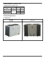
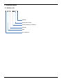
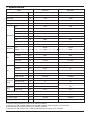
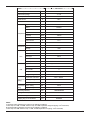
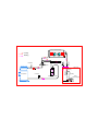
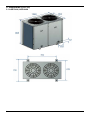
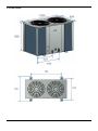
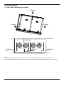
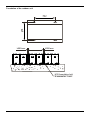
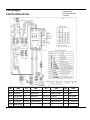
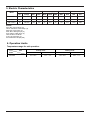
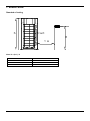
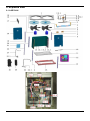
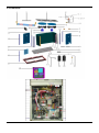
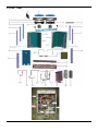
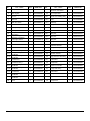
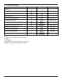
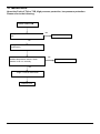
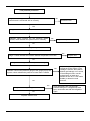
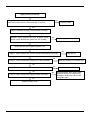
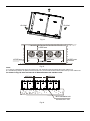
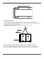
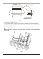
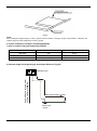
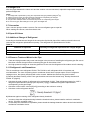
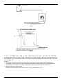
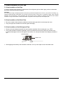
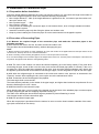
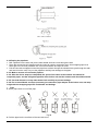
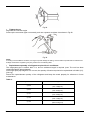
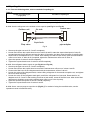
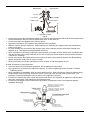
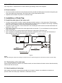
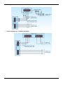
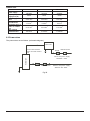
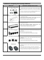
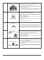
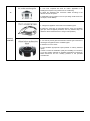
SERVICE MANUAL CONDENSING UNITS ASE-76AH, ASE-96AH, ASE-120AH Content Part 1 General Information .......................................... 2 Part 2 Outdoor Units .................................................... 5 Part 3 Installation ....................................................... 25 Part 4 Control ............................................................. 49 1 Part 1 General Information 1. Model Names of Outdoor Units ......................................... 3 2. External Appearance ......................................................... 3 3. Nomenclature ..................................................................... 4 2 1. Model Names of Outdoor Units 1.1 Model Names of Outdoor Units: Outdoor unit Capacity Power supply Model ASE-76AH ASE-96AH ASE-120AH 380~415V3N-50Hz kW Btu/h 22 76 28 96 35 120 2. External Appearance 2.1 Outdoor Unit ASE-76AH ASE-96AH ASE-120AH Btu/h 3 3. Nomenclature 3.1 Outdoor unit: A S E - 76 A H Heating Refrigerant R410A Cooling capacity (76 kBtu/h) External Split Air conditioner 4 MOV 120C(H) Part 2 Outdoor Units 1. Specifications .................................................................. 6 2. Dimension ........................................................................ 8 3. Service Space ..................................................................10 4. Wiring Diagrams ..............................................................12 5. Electric Characteristics ...................................................13 6. Operation Limits ..............................................................13 7. Sound Levels ...................................................................14 8. Exploded View .................................................................15 9. Troubleshooting...............................................................21 10. Malfunctions.....................................................................22 5 1. Specifications ASE-76AH Model Power supply - 380~415V-3N-50Hz ASE-96AH 380~415V-3N-50Hz Ambient temp range ? -7~52 -7~52 Rated input W 11700 14400 Rated current A 19.3 23.7 dB(A) 65 67 Type - scroll scroll Brand - Copland Copland Model - ZP90KCE-TFD-522 ZP120KCE-TFD-522 Qty. - 1 1 Btu/h 74500 100000 Input W 6950 9110 Rated current A 12.3 16.6 Locked rotor Amp A 110 110 Type - R410A R410A Charge g 5400 6000 Type - Axial fan Axial fan Dimension mm Φ530 Φ530 Drive type - Direct Direct Motor input W 310+292 670+644 Motor speed rpm 928/942 1250/1220 - Copper tube and aluminum fin mm Φ7.94 Φ7 No. of rows - 2 3 Fin per inch FPI 18 19 Length x height mm 2185x880 2179x882 Liquid side / Gas side mm Φ9.52/Φ22 Φ9.52/Φ25 Max. pipe length m 50 50 Max. difference in level m 30 30 Noise level Compressor Refrigerant Fan Capacity Type Tube size Coil Refrigerant piping Connection wiring Copper tube and aluminum fin Power wiring mm 2 5x6.0 5x6.0 Signal wiring mm 2 4x1.0 4x1.0 Dimension (WxHxD) mm 1260x908x700 1260x908x700 Packing (WxHxD) mm 1320x1060x730 1320x1060x730 Net / Gross weight kg 174/193 187/204 Shipping Qty per 20'/40'/40'HD pcs 24/54/54 24/54/54 Notes: 1. Nominal cooling capacities are based on the following conditions: Indoor temp: 27°CDB, 19°CWB; Outdoor temp: 35°CDB; Equivalent refrigerant piping: 7.5m (horizontal) 2. Nominal heating capacities are based on the following conditions: Indoor temp: 20°CDB; Outdoor temp: 7°CDB, 6°CWB; Equivalent ref. piping: 7.5m (horizontal) 6 ASE-120AH Model Power supply - 380~400V-3N-50Hz Ambient temp range ? -7~52 Rated input W 17300 Rated current A 28.6 dB(A) 69 Type - scroll Brand - Danfoss Model - SH140A4ALC Qty. - 1 Btu/h 118000 Input W 10862 Rated current A 21.4 Locked rotor Amp A 147 Type - R410A Charge g 7200 Type - Axial fan Dimension mm Φ531 Drive type - Direct Motor input W 621+587 Motor speed rpm 1230/1180 - Copper tube and aluminum fin mm Φ7 Noise level Compressor Refrigerant Fan Capacity Type Tube size Coil No. of rows 3 Fin per inch FPI 19 Length x height mm 1376x880 mm Φ12.7 / Φ28.6 m 50 Liquid side / Gas side Refrigerant Max. pipe length piping Max. difference in level m 30 Connection Power wiring wiring Signal wiring mm 2 mm 2 Dimension (WxHxD) mm 1260x908x700 Packing mm 1320x1060x730 Net / Gross weight kg 201/217 Shipping Qty per 20'/40'/40'HD pcs 24/54/54 (WxHxD) 5x6.0 4x1.0 Notes: 1. Nominal cooling capacities are based on the following conditions: Indoor temp: 27°CDB, 19°CWB; Outdoor temp: 35°CDB; Equivalent refrigerant piping: 7.5m (horizontal) 2. Nominal heating capacities are based on the following conditions: Indoor temp: 20°CDB; Outdoor temp: 7°CDB, 6°CWB; Equivalent ref. piping: 7.5m (horizontal) 7 Outdoor heat-exchanger Cooling Heating 4-way valve Stop valve HP Switch Stop valve T3 Indoor unit Discharge temp. sensor LP Switch Liquid-gas seperator Check valve Compressor Capillary Capillary Indoor heat-exchanger T2 T4 2. Dimension (Units: mm) 2.1 ASE-76AH, ASE-96AH 8 2.2 ASE-120AH 9 3. Service Space 3.1 ASE-76AH, ASE-96AH, ASE-120AH Air outlet Air inlet Air inlet ≥1000 mm ≥500 mm ≥1000 mm ≥1000 mm ≥1000 mm Note: 1. In case any obstacles exist above the outdoor unit, such obstacles must be 2000mm above the outdoor unit. 2. If miscellaneous articles are piled around the outdoor unit, such articles must be 400mm below the top of the outdoor unit. 10 Foundation of the outdoor unit 676 762 ≥500 mm ≥500 mm M12 foundation bolt 4 screws for 1 unit 11 4. Wiring Diagrams 1 - Compressor Output 2 - S.V.O (4 Way Valve Output) 3 - FAN Output 4.1 ASE-76AH, ASE-96AH, ASE-120AH 4-N Item COMP FAN1-2 CAP1-2 S.V KM(1) XT4-10 12 Name Compressor Outdoor fan Fan capacitance 4-way valve AC contactor Middle wire joint Item HEAT(A) CT1 XT1-2 XT3 H-PRO(A) - Name Crank Current detector 4-way terminal 3-way terminal High pressure switch - Item RT3A RT4 XS1-5, XP1-5 L-PRO(A) K1 - Name Pipe temp. sensor Room temp. sensor Connectors Low pressure switch Temp. protect switch - Item T1 SW1-3 C1-3 KM1-2 CN8-208 - Name Transformer Switch Filter capacitor Relay P.C. board socket - 5. Electric Characteristics Model Outdoor Unit Power Supply Compressor OFM Hz Voltage Min. Max. MCA TOCA MFA MSC RLA KW FLA ASE-76AH 50 380-415 342 438 17.5 18 20.5 86 16.5 0.573 2.613 ASE-96AH 50 380-415 342 438 20 21 23.8 110 20 1.373 6.26 ASE-120AH 50 380-400 342 440 25 28.6 30 147 21.4 1.373 6.26 Remark: MCA: Min. Current Amps. (A) TOCA: Total Over-current Amps. (A) MFA: Max. Fuse Amps. (A) MSC: Max. Starting Amps. (A) RLA: Rated Locked Amps. (A) OFM: Outdoor Fan Motor. FLA: Full Load Amps. (A) KW: Rated Motor Output (kW) 6. Operation Limits Temperature range for unit operation: Cooling mode Item Model All model Heating mode Outdoor Indoor Outdoor Indoor 21℃~52℃ 17℃~32℃ -10℃~24℃ 20℃~27℃ 13 7. Sound Levels Standard of testing h Front H 1 m Note: H = (h+1) / 2 14 Model H ASE-76AH 63 ASE-96AH 64 ASE-120AH 65 Noise level (dB(A)) 8. Exploded View 8.1 ASE 76AH 15 No. Part Name QTY BOM Code No. Part Name QTY BOM Code 1 top cover welding part 1 201275990072 12.9 Wire joint 1 202301450121 2 four-way valve ass'y 1 201675990299 12.10 Wire joint 7 202301450122 2.1 Pressure controller 1 202301820042 12.11 Wire joint 1 202301450130 2.2 4-way valve 1 201600600110 12.12 Three-phase power protection devices 1 202301600518 2.3 4-Ways valve solenoid 1 201600600179 13 front-right support pillar 1 201275990070 2.4 Valve body 1 201601600314 14 asynchronism fan motor 2 202400400563 2.5 Pipe joint 2 201601200004 15 condensor ass'y 1 201575990016 1 201275990060 15.1 condensor 1 201575990007 1 201275990073 15.2 condensor input pipe ass'y 1 201675990282 condensor output ass'y 1 201675990281 3 4 Electronic control box mounting plate fan motor supproting ass'y 5 The air grille 2 201275990062 15.3 6 Axial fan 1 201200300014 16 Axial fan 1 201200300035 7 Handle 2 201148700003 17 The partition 1 201275990066 8 After the column about 2 201275990068 18 Left panel 1 201275990064 9 Right front panel 1 201275990063 19 Before the column 1 201275990069 10 Under electronic control box mounting plate 1 201275990061 20 front-left pillar ass'y 1 201275990095 11 Chassis Parts 1 201275990097 21 Electronic control box cover 1 201275990065 12 outdoor electric box ass'y 1 203375990018 22 back middle pillar 1 201275990092 12.1 electric box welding ass'y 1 201275990107 23 Wooden chassis 1 202675990010 1 201275990087 24 compressor suction pipe ass'y 1 201675990302 1 201375990006 24.1 pressure controller 1 202301800953 12.2 12.3 wiring base installation ass'y Outdoor control board assembly 12.4 Capacitor 2 202300320025 25 Gas-liquid separator 1 201601100097 12.5 Relay 2 202300800071 26 coopland compressor 1 201401400710 12.6 AC contactor 1 202300850050 27 high pressure valve ass'y 1 201675990293 12.7 Transformer 1 202300900093 27.1 Valve body 1 201601600312 12.8 Wire joint 1 202301450110 - - - 16 - 8.2 ASE-96AH 17 No. QTY BOM Code 1 Welding together pieces of roof QTY BOM Code 1 201275990102 12.8 Wire joint 1 202301450130 2 Four-way valve assembly 1 201675990271 12.9 Three-phase power protection devices 1 202301600518 2.1 Pressure controller 1 202301820042 12.10 Compressor capacitor 2 202401000410 2.2 4-way valve 1 201600600110 13 Front right column 1 201275990109 2.3 4-Ways valve solenoid 1 201600600113 14 Induction motor 2 202400400456 2.4 Cube Valve 1 201601601291 15 Condenser components 1 201575990014 2.5 Pipe joint 1 201601200004 15.1 Condenser 1 201575990015 3 Electronic control box mounting plate 1 201275990060 15.2 1 201675990258 4 Motor bracket assembly 1 201275990106 15.3 1 201675990244 5 The air grille 2 201275990062 16 Axial fan 1 201200300035 6 Axial fan 1 201200300014 17 The partition 1 201275990066 7 Handle 2 201148700003 18 Left panel 1 201275990064 8 After the column about 2 201275990068 19 Before the column 1 201275990069 9 Right front panel 1 201275990063 20 1 201275990104 10 Under electronic control box mounting plate 1 201275990061 21 1 201275990065 11 Chassis Parts 1 201275990097 22 After the column 1 201275990067 12 Outdoor electronic control box components 1 203375990015 23 Wooden chassis 1 202675990010 12.1 Outdoor control board assembly 1 201375990006 24 Components of the compressor back to the trachea 1 201675990267 12.2 Relay 2 202300800071 24.1 Pressure controller 1 202301820021 12.3 Contactor 1 202300850034 24.2 Pipe joint 1 201601200004 12.4 Transformer 1 202300900093 25 Gas-liquid separator 1 201601100097 12.5 Wire joint 1 202301450110 26 Copeland Compressor 1 201401400620 12.6 Wire joint 1 202301450121 27 High-pressure valve assembly 1 201675990269 12.7 Wire joint 7 202301450122 27.1 Cube Valve 1 201601600316 18 Part Name No. Part Name Input tube condenser components Output tube condenser components Components before the left column Electronic control box cover 8.3 ASE AH 19 No. Part Name QTY BOM Code No. Part Name Bottom mounting plate of electronic control box Outdoor electronic control box components QTY BOM Code 1 201275990079 1 203375990015 1 201275990107 1 201275990087 1 201375990006 1 The partition 1 201275990085 21 2 The air grille 2 201275990062 22 4 Welding together pieces of roof 1 201275990102 22.1 5 Axial fan 1 201200300035 22.2 6 After the column 1 201275990117 22.3 7 After the column about 4 201275990068 22.4 Relay 2 202300800071 8 Gas-liquid separator 1 201601100097 22.5 Contactor 1 202300850034 9 Front panel 1 201275990084 22.6 Transformer 1 202300900093 1 201275990118 22.7 Wire joint 1 202301450110 1 201275990080 22.8 Wire joint 1 202301450121 10 11 Components before the left column Top mounting plate of electronic control box electric box welding ass'y wiring base installation ass'y Outdoor control board assembly 12 Front right column 1 201275990116 22.9 Wire joint 7 202301450122 13 Induction motor 2 202400400456 22.10 Wire joint 1 202301450130 14 Axial fan 1 201200300014 22.11 Three-phase power protection devices 1 202301600518 15 Motor bracket assembly 1 201275990106 22.12 Compressor capacitor 2 202401000410 16 Condenser ass'y II 1 201575990019 23 Chassis Parts 1 201275990111 1 201675990337 24 Wooden chassis 1 202675990010 1 201675990345 25 High pressure valve ass'y 1 201675990363 Condenser II 1 201575990020 25.1 Cube Valve 1 201601600316 Condenser ass'y I 1 201575990017 26 Suction pipe ass'y of compressor 1 201675990356 1 201675990305 26.1 pressure controller 1 202301800953 1 201675990321 27 4-way valve ass'y 1 201675990359 1 201575990018 27.1 Cube Valve 1 201601601292 1 201675990384 27.2 4-way valve 1 201600600110 1 201675990367 27.3 Pressure controller 1 202301820020 1 201275990065 28 Compressor 1 201402300130 16.1 16.2 16.3 17 17.1 17.2 17.3 18 19 20 20 Inlet pipe ass'y of condenser Outlet pipe ass'y of condenser Inlet pipe ass'y of condenser Outlet pipe ass'y of condenser Condenser I Inlet pipe ass'y II of condenser Inlet pipe ass'y of condenser Electronic control box cover 9. Troubleshooting Type LED1 LED2 Remarks Standby ☆ ☆ - Cooling mode ◆ ◇ - Heating mode ◆ ◆ - Defrosting mode ◇ ◆ - Phase sequence protection ◆ ●★ Manual reset Communication failure ◆ ●●★ Manual reset Outdoor condenser temp. sensor error ◆ ●●●★ Manual reset Outdoor ambient temp. sensor error ◆ ●●●●★ Manual reset Protection of low pressure ◇ ●★ Auto reset Protection of high pressure ◇ ●●★ Auto reset Protection of over-current ◇ ●●●★ Auto reset Protection of condenser hi-temp. ◇ ●●●●★ Auto reset Note: ☆: Light for 1 second, extinguish for 1 second; ◆: Light; ◇: Extinguish; ●: Light for 0.4 second, extinguish for 0.4 second; ★: Light for 2 second, extinguish for 2 second. 21 10. Malfunctions: About the Fault of T3A or T3B, High pressure protection, low pressure protection. Please refer to the following: Fault of T3A or T3B Judge 1: Whether the sensor is break off. Yes Connects it well. No Judge 2: Whether the sensor is malfunction. Validate: Short-connect the outdoor ambient temperature sensor, check whether it can run normally No Judge 3: PCB is malfunction Replace PCB 22 Yes Replace it. Low pressure protection Judge 1: The wiring between the low pressure switch and main control board is connected well or correctly No Connect it well Yes Judge 2: Whether the low pressure switch is broken Validate: Short connect the low pressure switch socket, check whether the system can run normally Yes Replace low pressure switch No Check whether the refrigerant system is ok Judge 3: Check whether the outdoor ambient temperature is too low Yes Stop the unit No Judge 4: The refrigerant of the system is leakage Validate: Connect the pressure gauge to the gauge joint of the system, check whether the pressure is lower than 0.15MPa No Yes Judge 5: The refrigerant pipe is blocked No Yes Leak hunting: charge nitrogen or refrigerant to the system, if the leakage is serious, there will be distinct gas leakage “cici” sound; if the leakage is little, use the suds(mixture of water and abluent is also ok, if it can make bubble) or electronic leak detector. Drop refrigerant, then use the high pressure nitrogen or refrigerant to blow pipe, vacuumize and add the refrigerant again Replace outdoor PCB 23 High pressure protection No Judge 1: Whether the wiring between the high pressure switch and main control board is connected well or correctly Connect it well Yes Judge 2: Whether the high pressure switch is broken Validate: Short connect the high pressure switch socket, check whether the system can run normally Yes Replace high pressure switch No Check whether the refrigerant system is ok Judge 3: Check whether the outdoor ambient temperature is too high No Judge 4: Check whether the outdoor unit is bad ventilation No Judge 5: Check whether the heat exchanger is dirty No Judge 6: Check whether the refrigerant pipe is blocked No Replace outdoor PCB 24 Yes Yes Yes Yes Stop the unit Make the outdoor unit ventilate well Clean the heat exchanger Drop refrigerant, then use the high pressure nitrogen or refrigerant to blow pipe, vacuumize and add the refrigerant again Part 3 Installation 1. Note ...............................................................................26 2. Installation of Outdoor Units ......................................27 3. Heat Insulation of the Pipe ..........................................35 4. Installation of Connective Pipe...................................36 5. Installation of Drain Pipe .............................................41 6. Electric Connection .....................................................42 7. Methods of configuring and selecting installation ....45 25 1. Note CAUTION: Install the unit where enough space of installation and maintenance is available. Install the unit where the ceiling is horizontal and enough for bearing the weight of the indoor unit. Install the unit where the air inlet and outlet are not baffled and are the least affected by external air. Install the unit where the supply air flow can be sent to all parts in the room. Install the unit where it is easy to lead out the connective pipe and the drain pipe. Install the unit where no heat is emitted from a heat source directly. Installing the equipment in any of the following places may lead to faults of the equipment (if that is inevitable, consult the supplier): The site contains mineral oils such as cutting lubricant. Seaside where the air contains much salt. Hot ring area where corrosive gases exist, e.g., sulfide gas. Factories where the supply voltage fluctuates seriously. Inside a car or cabin. Place like kitchen where oil permeates. Place where strong electromagnetic waves exist. Place where flammable gases or materials exist. Place where acid or alkali gases evaporate. Other special environments. Install the unit where enough space of installation and maintenance is available. Install the unit where the air inlet and air outlet are free from obstacles and strong wind. Install the unit in a dry and well ventilated place. Install the unit where the bearing surface is level and can bear weight of the unit, and is suitable for installing the unit horizontally without increasing noise or vibration. Install the unit where the operation noise and the expelling of air do not affect neighbors. Install the unit where no flammable gas is leaked. Install the unit where it is convenient for pipe connection and electric connection. 26 2. Installation of Outdoor Units 2.1 Important: Construction Checkpoints 1). Installation Check the model and name to avoid mistaken installation. 2). Refrigerant pipe The refrigerant pipes must have the specified diameter. Nitrogen of a certain pressure must be filled into the refrigerant pipe before welding. The refrigerant pipe must undergo heat insulation treatment. After the refrigerant pipe is installed completely, the indoor unit cannot be powered on before performing the airtight test and creating a vacuum. 3). Pressure test The refrigerant pipe must undergo the airtight test [with 2.94MPa (30kgf/cm2G) nitrogen]. 4). Creating a vacuum Be sure to use the vacuum pump to create a vacuum of the connective pipe at both air side and liquid side concurrently. 5). Refrigerant replenishment If the pipe is longer than the reference pipe, the refrigerant replenishment quantity for each outdoor unit should be calculated through the formula obtained according to the actual length of the pipe. Record the refrigerant replenishment quantity, actual length of pipe and the height difference of the indoor & outdoor units onto the operation confirmation table (on the electric control box) of the outdoor unit in advance for future reference. 6). Electric wiring Select the power supply capacity and wire size according to the design manual. The power wire size of the air conditioner should be greater than that of ordinary motors. In order to prevent disoperation of the air conditioner, do not interleave or entwine the power cable (380~415V/3N/50Hz) with the connection wires (low-voltage wires) of the indoor/outdoor unit. Power on the indoor unit after performing the airtight test and making a vacuum. 7). Trial run Perform the trial run only after the outdoor unit has been powered on for over 12 hours. 2.2 Installation Space When installing the unit, leave a space for maintenance shown in the following figure. Install the power supply at the side of the outdoor unit. Ensure enough space for installation and maintenance. (Fig-14 and Fig-15) 27 Air outlet Air inlet Air inlet Fig-14 ≥1000 mm ≥500 mm ≥1000 mm ≥1000 mm ≥1000 mm Fig-15 NOTE: 1. In case any obstacles exist above the outdoor unit, such obstacles must be 2000mm above the outdoor unit. 2. If miscellaneous articles are piled around the outdoor unit, such articles must be 400mm below the top of the outdoor unit. As shown in Fig-16, leave an interval of 500mm between the outdoor units. ≥500 mm ≥500 mm M12 foundation bolt 4 screws for 1 unit Fig-16 28 The distance of the foundation bolt is shown in Fig-17. 676 762 Fig-17 2.3 Convey Outdoor Unit Use 4 steel ropes of a Ф6mm or bigger size to hoist the outdoor unit and convey it into the room. In order to prevent scratch and deformity the outdoor unit, apply a guard board to the surface of contact between the steel ropes and the air conditioner. Remove the cushion for use in the transport after finishing the transport. (Fig-18) Fork truck can be used for conveying. Steel wire Guard board Base and bracket Holes for fork truck Fig-18 2.4 Snow protection facilities must be installed in the snowfall areas. (Fig-19) In case the snow protection facilities are incomplete, faults may occur. In order to prevent influence caused by snow, set up raised pavilion, and install snow protection sheds at the air inlet and air outlet. 29 Snow protection Snow protection shed at the air outlet shed at the air inlet Snow protection shed at the air inlet Fig-19 2.5 Installation of Refrigerant Pipe The refrigerant pipe adapter is located inside the outdoor unit. When the pipe is connected from the front side, the pipe can be let out through the right front board. (Fig-20 and Fig-21) So remove the left front board first. (Three M5 screws) The pipe can be connected from the front left lower side or the bottom notch of the outdoor unit. When the pipe is connected from the front side, the pipe can be led out through the pipe & wire panel. In case the pipe is connected from the bottom notch, install it leftward, rightward or backward after leading it out. When the pipe is led from the front, use a cover plate to seal the bottom notch in order to prevent intrusion of dust or trash. Fig-20 30 Fig-21 NOTE: When welding the refrigerant pipe, in order to prevent internal oxidation of the pipe, nitrogen must be filled in. Otherwise, the oxidized chips may block refrigerating circulatory system. 2.5.1 Size of Outdoor Unit Pipes and Piping Methods 1) Size of outdoor unit pipes and piping methods Model Gas side ASE-76AH Liquid side Φ22 Φ9.52 ASE-96AH Φ25 Φ9.52 ASE-120AH Φ28.6 Φ12.7 2) Allowed length of refrigerant pipe and height difference (Fig-22) Height difference between indoor unit and outdoor unit H 30m Outdoor unit Max. pipe length L 50m Indoor unit . Fig-22 31 Table 1: 76000, 96000 Btu/h 120000 Btu/h 50m 50m Outdoor upper 30m 30m Outdoor lower 30m 30m Max. equivalent length of pipe (L) Max. height difference Height difference between indoor unit and outdoor unit (H) 3) Connection between indoor unit and outdoor unit (Fig %WXK Fig-23 32 2.6 Airtight Test After the pipes between the indoor unit and the outdoor unit are connected, replenish compressed nitrogen to perform airtight test. NOTE: 2 1. The airtight test is performed by using the compressed nitrogen [2.94MPa (30kg/cm G)]. 2. Tighten the spool of the gas valve and liquid valve before compressing the nitrogen. 3. Compress the nitrogen at the air vent of the gas valve. 4. The gas valve and liquid valve are closed in the process of compressing the nitrogen. 5. Do not use oxygen, flammable gas or toxic gas in the airtight test. 2.7 Vacuumize Use a vacuum pump to make a vacuum. Do not use refrigerant gas to expel air. When making the vacuum, start from the air side. 2.8 Open All Valves 2.9 Additional Charge of Refrigerant According to the diameter and length of the connective liquid side pipe of the outdoor unit and indoor unit, calculate the refrigerant replenishment quantity. The refrigerant for replenishment is R410A. Table 2: Diameter of liquid line Quantity of refrigerant replenished for 1m pipe length φ 9.52 φ 12.7 0.060kg 0.115kg 2.10 Remove Trash and Moist in the Pipe Trash and foreign matters may come into the pipe in the process of installing the refrigerant pipe. Be sure to blow them off with nitrogen before connecting the pipe to the outdoor units. Use high-pressure nitrogen to clean the pipelines. Do not use the refrigerant of the outdoor unit for cleaning. 2.11 Refrigerant Leak Precautions This air conditioner uses refrigerant R410A. The R410A is safe refrigerant which is harmless and non-flammable. The room for placing the air conditioner should have a proper space. Even if refrigerant leakage occurs, the density threshold will not be crossed. Additional measures may also be taken. 1) Density threshold: Density of the Freon gas that does not harm the human body. Density threshold of R410A: 0.3 [kg/m3] Calculate the total quantity of refrigerant to be replenished (A [kg]). Total refrigerant quantity for 10HP = refrigerant replenishment quantity upon shipment (11[kg]) + additional refrigerant replenishment corresponding to the pipe length Calculate out the indoor volume (B [m3]) (according to the minimum volume) Calculate out the refrigerant density: 2) Measures against crossing of the refrigerant density threshold In order to keep the refrigerant density below the threshold value, please install a mechanic ventilation device. (Perform ventilation often) In case frequent ventilation is impossible, please install the leakage detection alarm device linked with the mechanical ventilation device. 33 Outdoor unit Room in which refrigerant is leaked (All refrigerant is leaked) Fig-24 Fig-25 &RPSOHWLQJWKH&RQQHFWLRQ6\VWHP1DPH In case multiple systems are set, in order to identify the connection system of the indoor unit and outdoor unit, it is necessary to give name to each system, and mark it onto the nameplate on the electric control box cover of the outdoor unit. 127( : The indoor unit and outdoor unit are categorized into system A and system B. When installing and connecting the indoor unit and outdoor unit, identify the label carefully, and make sure that indoor unit corresponds to the outdoor unit exactly. Otherwise, it may lead to fault of the air conditioner. Model of indoor unit. Room name Example: the first system indoor unit A of the 2nd floor is recorded as: 2F 1A. 34 3. Heat Insulation of the Pipe 3.1 Heat Insulation of the Pipe In order to prevent faults caused by condensate of the refrigerant pipe and drain pipe, perform condensate prevention and heat insulation properly. CAUTION: If it is forecast that high humidity/temperature environment (condensate temperature is over 23℃) may exist in the ceiling, e.g., inside the ceiling with slab, ceiling which is in the same environment as the outdoor air), it is necessary to apply 10mm or thicker adiabatic wool (16~20kg/m2 ) to the refrigerant pipe and the drain pipe in addition to applying the general heat insulation materials. Enough heat insulation materials should also be applied to the refrigerant joint and the pipe joint. 3.2 Heat Insulation of the Drain Pipe Be sure to entwine heat insulation materials round the drain pipe which runs through the room. Carry through heat insulation for the drain pipes thoroughly. 3.3 Heat Insulation of the Refrigerant Pipe Please use heat-resistant materials as heat insulation materials of the air-side pipe. (e.g., EPT) Cover heat insulation materials separately at the liquid side and the air side. Moreover, perform heat insulation thoroughly for the air-side pipes of the indoor unit, and prevent water from dripping outside the unit. (air-side pipe) Indoor unit Fig-26 After applying the auxiliary heat insulation materials, use vinyl resin tape to seal it lest water leak. 35 4. Installation of Connective Pipe 4.1 Preparation before Installation Check the height difference between the indoor unit and the outdoor unit, and check the length and number of bends of the refrigerant pipeline, which must meet the following requirements: Max. Height difference....30m (If the height difference is greater than 5m, it is better to put the outdoor unit above the indoor unit). Max. Pipeline length.........50m Max. Number of bends.....15 In the process of installing the connective pipe, do not lemmas the air, dust or foreign substance intrudes into the pipeline system. Install the connective pipe only after fixing the indoor and outdoor units. Keep dry when installing the connective pipe. Do not let moist intrude into the pipeline system. 4.2 Procedure of Connecting Pipes 5.2.1 Measure the required length of the connective pipe, and make the connective pipes in the following procedure. 5.2.1.1 Connect the indoor unit first, and then connect the outdoor unit. The pipe bend should be handled carefully, without damaging the pipe. NOTE: 1. Before screwing up the flared nut, apply refrigerant oil at the outer surface of the pipeline flare and the taper surface of the connection nut. Screw up the nut for 3~4 circles beforehand. 2. When connecting or disconnecting the pipeline, be sure to use two spanners concurrently. 3. Do not rest the weight of the connective pipe on the adapter of the indoor unit. Too heavy load on the adapter of the indoor unit may deform the pipe and thus affect the cooling/heating effect. 4.2.1.2 The valve of the outdoor unit should be closed completely (as in the factory status). Every time when connecting the pipe, screw off the nut at the valve, and connect the flared pipe (within 5 minutes). If the nut is put away for a long time after being screwed off the valve, dust and other foreign substance may intrude into the pipeline system and lead to fault. Before connecting the pipe, use the refrigerant to expel air out of the pipe. 4.2.1.3 After the refrigerant pipe is connected to the indoor and outdoor units, expel air as instructed in the “Expel air” section. After expelling the air, screw up the nut at the maintenance orifice. 4.2.1.4. Precautions for the flexible part of the pipeline The bend angle shall not exceed 90°. The bend shall be preferably in the middle of the pipe length, and higher bend radiuses are preferred. Do not bend the flexible pipe for over 3 times. 4.2.1.5 Bend the thin-wall connective pipe When bending the pipe, cut out a notch of the desired size at the bend of the adiabatic pipe, and then expose the pipe (wrap the pipe with the wrapping tape after bending it). The radio of the elbow pipe should be as large as possible to prevent flattening or crush. Use the pipe bender to make close elbow pipe. 4.2.1.6 Use purchased copper pipe When the cooper pipe is purchased from the market, be sure to use the heat insulation materials of the same type (with a thickness of over 9mm). 36 Fig-27 4.2.2 Deploy the pipelines Drill a porthole on the wall, and put the hole sheath and hole cover through the wall. Place the connective pipe together with the indoor & outdoor connection wires. Use wrapping tape to tie them tight. Do not let air penetrate into it lest condensation and drips of moist. Pull the connective wrapped connective pipe from outdoor through the sheath which gets through the wall, and lead it into the room. Lay out the pipelines carefully lest damage to the pipes. 4.2.3. Make a vacuum of connective pipeline. 4.2.4. After the above steps are completed, the spool of the valve of the outdoor unit should be completely open, and the refrigerant pipeline of the indoor unit and the outdoor unit should be smooth. 4.2.5. Use leak detector or soap water detect leak carefully to prevent leakage. 4.2.6. Put on an adiabatic envelope (accessory) at connective pipe adapter of the indoor unit, and wrap it tight with the wrapping tape lest condensate and leakage. Flare a. Use a pipe cutter to cut off the pipe. Fig-28 b. Pull the pipe into the rear flare of the connective nut. 37 Fig-29 Tighten the nut Align with the connective pipe Screw up the connection pipe nut manually, and use a spanner to tighten it as shown in Fig-38 Fig-30 NOTE: According to the installation conditions, too large torque will damage the flaring, and too small torque will lead to looseness and leakage. Determine the tightening torque by reference to the following table. Replenishment quantity of refrigerant required for air conditioner The single-pass pipe is shorter than 5 m, and no additional length is required (note: The unit has been replenished before being shipped). If the single-pass pipe length is 5 m or more, the quantity of fluorine required to be replenished is 0.060X (L-5). (Unit: kg) Record the replenishment quantity of the refrigerant and keep the record properly for reference in future maintenance. Table 3: 38 Pipe diameter Torque φ 6.35 1420~1720N.cm (144~176kgf.cm) φ 9.53 3270~3990N.cm (333~407kgf.cm) φ 12.7 4950~6030N.cm (504~616kgf.cm) φ 16.0 6180~7540N.cm (630~770kgf.cm) φ 19.0 9720~11860N.cm (990~1210kgf.cm) 4.3 Expelling Air 4.3.1. From the following table, select a method of expelling air. Table 4: Length of connective pipe (single pass) Procedure of expelling air Less than 5m Use refrigerant in the outdoor unit 5~15m Use vacuum pump or refrigerant tank. If the air conditioner is relocated, be sure to use a vacuum pump or refrigerant tank to expel air. 4.3.1.2. Use the refrigerant in the outdoor unit to expel air (see Fig-31 and Fig-32) Outdoor unit Intdoor unit Air side C A D B Stop valve Liquid side pipe adapter Fig-31 Screw up the pipe nuts at A, B, C and D completely. Loosen and remove the square-head cover of valves A and B, rotate the square-head spool of valve B counterclockwise for 45 degrees and stay for about 10 seconds, and then close the spool of valve B tightly. Detect leak for all adapters at A, B, C and D. After making sure that no leak exists, open the maintenance orifice nut of valve A. After all air is expelled, tighten the maintenance orifice nut of valve A. Open the spools of valves A and B completely. Tighten the square-head cover of valves A and B completely. 4.3.1.3. Use refrigerant tank to expel air (see Fig.6-8 and Fig.6-9) Screw up the pipe nuts at A, B, C and D completely. Loosen and remove the square-head cover and the maintenance orifice nut of valves A and B. Connect the filler hose of the refrigerant tank with the maintenance orifice of valve A. Loosen the valve of the refrigerant tank, continue filling refrigerant for 6 seconds to expel the air, and tighten the nut of valve B quickly. Loosen the valve of the refrigerant tank again, and fill the refrigerant for 6 seconds. Detect leak for all adapters at A, B, C and D. After making sure that no leak exists, screw off the filler hose. After all the filled refrigerant is expelled, screw up the maintenance orifice nut of valve A quickly. Open the square-head spools of valves A and B completely. Tighten the square-head cover of valves A and B. 4.3.1.4. Use a vacuum pump to expel the air (Fig-32) (For method of using the manifold valve, see the operation manual of manifold valve): 39 Manifold valve Multimeter manometer -76cmHg Hi -handle Lo-handle Filler hose Vacuum pum p Filler hose Lo pressure valve Fig-32 Loosen and remove the maintenance orifice nut of valve A, and connect the filler hose of the manifold valve to the maintenance orifice of valve A (tighten both valve A and valve B). Connect the filler hose adapter to the vacuum pump. Open the low pressure (Lo) handle of the manifold valve completely. Start the vacuum pump to extract air. At the beginning of extracting air, slightly loosen the maintenance orifice nut of valve B, check whether any air enters it (the vacuum pump noise changes and the multi-meter indicate from negative to 0). Then tighten this maintenance orifice nut. Upon completion of vacuuming, tighten the low pressure (Lo) handle of the manifold valve completely and stop the vacuum pump. Keep extracting air for over 15 minutes. Check whether the multi-meter points at -1.0X10 Pa (-76cmHg). Loosen and remove the square-head cover of valves A and B. After opening valves A and B completely, tighten the square head cover of valves A and B. Remove the filler hose off the maintenance orifice of valve A, and then tighten the nut. 4.3.1.5. Procedure of using stop valve Open the spool until it touches the stop block. Do not attempt to open further. Use a spanner or a similar tool to tighten the bonnet. The bonnet tightening torque is shown in Table 3 “Tightening torque”. Upon completion of installation, open all valves before trial run. Each unit has two valves of different sizes located at the outdoor unit side. Of the two valves, one is gas valve and the other is liquid valve. The procedure of opening/closing the valve is shown in the right figure (Fig-33). Procedure of opening the valve: Open the square-head cover, use a spanner to capture the square head and open it thoroughly. Then tighten the square-head cover. Procedure of closing the valve: Same as the procedure of opening the valve, but rotate the spanner clockwise thoroughly. Fig-33 40 4.4 Leak Detection Use soap water or a leak detector to check whether gas leakage exists at the adapters. 4.5 Heat Insulation Use heat insulation materials to wrap the part protruding outside the flared pipe joint and the refrigerant pipe of the liquid pipe and the gas pipe, and ensure that no gap exists between them. Imperfect heat insulation may lead to condensate drips. 5. Installation of Drain Pipe 5.1 Install the drain pipe of the indoor unit Bush (Checking orifice) Bush (Checking orifice) Main drain pipe over 50m m over 100m m In order to prevent drain overflow, install a drainage controller at place 1 of the drain pipe. (The drainage controller is designed to smoothen the drainage when the static pressure outside the unit is high, especially at the air inlet, in addition to remove stink through the drain pipe.) The drain of water is natural. In the construction, the external pipe of the outdoor unit slants downward at a gradient of 1/50~1/100. The number of bends and folds of the drain pipe should not exceed 2. Try to avoid bends in order to prevent trash accumulation. In the construction, do not drop trash into the drip tray or drain pipe of the indoor unit. Upon completion of installing the drain pipe, remove the inspection panel. Put water into the drip tray to check whether the water can be drained levelly and steadily. Checking panel Checking panel Drain pipe Fig-34 NOTE: Drain pipe trash gains easily at the drainage controller. Be sure to install a stopper and a structure that cleans up trash easily. 5.2. Trial draining of the drain pipe Open the side panels of the indoor unit, fill water inward, and check whether the water can be drained smoothly. Check water leak at the joint. 5.3. Heat insulation of drain pipe After making sure that the water drains smoothly and no water is leaked, use adiabatic wool bushes to preserve heat of the drain pipe. Otherwise, condensate will occur. 41 6. Electric Connection 6.1 Electric field wiring CAUTION: Use special power supply for the air conditioner. Design power supplies specific to the indoor unit and outdoor unit. The supply voltage must comply with the nominal voltage. The external supply circuit of the air conditioner must have a ground wire, and the power supply ground wire of the indoor unit must be connected with the external ground wire firmly. The wiring must be performed by professional technicians according to the circuit diagram labels. Distribute the wires according to the relevant electric technical standards promulgated by the State, and set the Residual Current-operated Circuit Breaker (RCCB) properly. The power wire and the signal wire shall be laid out neatly and properly, without mutual interference or contacting the connection pipe or valve. No power cable is attached to this equipment. The user can select the power cable by reference to the stipulated power supply specifications. No joint of wires is allowed. Upon completion of wire connection, double check it and then connect the power supply. 42 6.1.1 Duct type - 76 kBtu/h; 96 kBtu/h; 120 kBtu/h: 6.1.2 Floor standing type - 76 kBtu/h; 96 kBtu/h: 43 Outdoor unit: Model ASE-76AH ASE-96AH ASE-120AH Power supply 380~415V3N-50Hz 380~415V3N-50Hz 380~415V3N-50Hz 60/40 60/40 60/40 YCW-450/750 2 4*6.0 mm YCW-450/750 2 6.0 mm YCW-450/750 2 4*6.0 mm YCW-450/750 2 6.0 mm YCW-450/750 2 4*6.0 mm YCW-450/750 2 6.0 mm RVV-300/500 2 4*1.0 mm RVV-300/500 2 4*1.0 mm RVV-300/500 2 4*1.0 mm RVVP-300/300 5*0.5mm² RVVP-300/300 5*0.5mm² RVVP-300/300 5*0.5mm² Capacity of power supply/ fuse (A) Power supply cable Grounded wire Connective wire of indoor to outdoor unit Wire controls connective wire 6.3 Power wires The power wires are as follows: (schematic diagram) Indoor unit Control wire between indoor unit and outdoor unit RCCB Manual switch Indoor unit power supply Outdoor unit 220-240V~ 50Hz RCCB Manual switch Outdoor unit power supply 380-415V 3N~ 50Hz Fig-35 44 7. Methods of configuring and selecting installation Material name Characteristics, advantages and other contents 1. Install the filter at the main body grille in case the storey height is low, and at the main body of the indoor unit in case the storey height is high. 1 2. It cleans conveniently at the time of installing/uninstalling the filter. 3. The button structure is easy to install and uninstall. ` 1. For purpose of air inlet. 2 2. Must adopt fire-resistant materials. (Those materials other than specified by Midea than specified by Midea be applied) 3. The heat insulation material must be glass wool. 1. For purpose of air outlet. 3 2. Must adopt fire-resistant materials. (Those materials other materials. (Those materials other shall not be applied) 3. The heat insulation material must be glass wool. 1. Install the unit at the air inlet so that the air flows smoothly and the noise is lower. 4 2. The noise value varies with the length. 3. The hose joint should be bent lest detachment of the pipe. 1. Install the unit at the air outlet so that the air flows smoothly and the noise is lower. 5 2. The noise value varies with the length. 3. The hose joint should be bent lest detachment of the pipe. 1. Install the unit at the air outlet so that the air flows smoothly and the noise is lower. 6 2. Select 1BY2 or 1BY3 according to the quantity of the diffusers. 3. The diffuser pipes should preferably have the same length after branching, and the minimum length of the ventilation pipes is 5m. 45 1. Fixed model that diffuses air at a 360 angle. 7 2. The outline size should increase when the air volume is over 350CMH. (For above 303), i.e., when about 9 diffusers are required, the outline size should increase. 3. The diffuser pipes should preferably have the same length after branching, and the minimum length of the ventilation pipes is 5m. 1. Fixed model that diffuses air at a 360 angle. 2. The outline size should increase when the air volume is over 350CMH. (For above 303), i.e., when about 9 diffusers are required, the outline size should increase. 8 3. Proper air speed: For air speed of over 2-3.5m/s, select other diffusers (with great noise). 4. Install the diffuser pipe if it is necessary to install the model of over 3.5m/s. 5. For purpose of cooling-only model. 1 The lengthwise adjustable model which diffuses air at a 360 angle. 9 2. With the change of the cooling/heating air flow, the horizontal and vertical distance of the fan can be adjusted (applicable to department store and exhibition hall where the decorative effect is essential). 1. Low noise compared with other air outlets. Applicable to tall buildings that require along distance of air conditioning. 10 2. Select the ventilation pipe connection caliber according to the distance and the air speed. 3. Applicable to storey height of over 5m (for design of tall storey such as temple, consult Midea). 1. The fan is the adjustable type which can change direction of air flow. It is used for deluxe decoration. 11 2. The outline size should increase when the air flow is over 450CMH (3 or 4 SOLT) when about 6 diffusers are required, the outline size should increase. 3. If the proper air speed is 2.5-5m/s and actual air speed reaches over 5m/s, it is necessary to choose other diffusers (with higher noise values). 46 1. Low noise compared with other air outlets. Applicable to tall buildings that require a long distance of air conditioning. 12 2. Select the ventilation pipe connection caliber according to the distance and the air speed. 3. Applicable to storey height of over 5m (for design of tall stores such as temple, consult Midea). 1. Flanges and pipelines connected to the ventilation pipes. 2. When the noise pipe is connected with the hose, the ventilation pipe tape must be applied (otherwise, with only adhesive tape, the adhesion will be weakened due to change of temperature). Auxiliary materials 1. It is used to prevent glass wool leak and seal the gas at the time of the flanges and pipelines of the ventilation pipes. 2. Entwine for over 3 circles. 3. Use ventilation pipe-specific tapes (instead of ordinary adhesive tapes). In order to ensure the installation quality and durability, it is necessary to use the auxiliary materials of standard specifications provided by Midea Electronics and the auxiliary products of the specified manufactures. 47 48 Part 4 Control 1. Central Control Monitor (Optional) ............................. 50 49 1&HQWUDO&RQWURO0RQLWRU2SWLRQDO &&0 1) 2YHUYLHZ %XWWRQVDQG)XQFWLRQV 50 Liquid Crystal Display: 51 2) Installation Note: To differentiate each centralized controller, the controllers in the same RS-485 net should be with different address with each other. NOTE: 1. Never turn screws too tightly, otherwise the cover would be dented, or the Liquid Crystal would be broken. 2. Do not cut wires when installing the cover of Central Control Monitor. 52 Appendix 1: Indoor Temp. and Pipe Temp. Sensor Resistance Value Table (℃--K) ℃ K Ohm ℃ K Ohm ℃ K Ohm ℃ K Ohm -20 115.266 20 12.6431 60 2.35774 100 0.62973 -19 108.146 21 12.0561 61 2.27249 101 0.61148 -18 101.517 22 11.5000 62 2.19073 102 0.59386 -17 96.3423 23 10.9731 63 2.11241 103 0.57683 -16 89.5865 24 10.4736 64 2.03732 104 0.56038 -15 84.2190 25 10.000 65 1.96532 105 0.54448 -14 79.3110 26 9.55074 66 1.89627 106 0.52912 -13 74.5360 27 9.12445 67 1.83003 107 0.51426 -12 70.1698 28 8.71983 68 1.76647 108 0.49989 -11 66.0898 29 8.33566 69 1.70547 109 0.48600 -10 62.2756 30 7.97078 70 1.64691 110 0.47256 -9 58.7079 31 7.62411 71 1.59068 111 0.45957 -8 56.3694 32 7.29464 72 1.53668 112 0.44699 -7 52.2438 33 6.98142 73 1.48481 113 0.43482 -6 49.3161 34 6.68355 74 1.43498 114 0.42304 -5 46.5725 35 6.40021 75 1.38703 115 0.41164 -4 44.0000 36 6.13059 76 1.34105 116 0.40060 -3 41.5878 37 5.87359 77 1.29078 117 0.38991 -2 39.8239 38 5.62961 78 1.25423 118 0.37956 -1 37.1988 39 5.39689 79 1.21330 119 0.36954 0 35.2024 40 5.17519 80 1.17393 120 0.35982 1 33.3269 41 4.96392 81 1.13604 121 0.35042 2 31.5635 42 4.76253 82 1.09958 122 0.3413 3 29.9058 43 4.57050 83 1.06448 123 0.33246 4 28.3459 44 4.38736 84 1.03069 124 0.32390 5 26.8778 45 4.21263 85 0.99815 125 0.31559 6 25.4954 46 4.04589 86 0.96681 126 0.30754 7 24.1932 47 3.88673 87 0.93662 127 0.29974 8 22.5662 48 3.73476 88 0.90753 128 0.29216 9 21.8094 49 3.58962 89 0.87950 129 0.28482 10 20.7184 50 3.45097 90 0.85248 130 0.27770 11 19.6891 51 3.31847 91 0.82643 131 0.27078 12 18.7177 52 3.19183 92 0.80132 132 0.26408 13 17.8005 53 3.07075 93 0.77709 133 0.25757 14 16.9341 54 2.95896 94 0.75373 134 0.25125 15 16.1156 55 2.84421 95 0.73119 135 0.24512 16 15.3418 56 2.73823 96 0.70944 136 0.23916 17 14.6181 57 2.63682 97 0.68844 137 0.23338 18 13.9180 58 2.53973 98 0.66818 138 0.22776 19 13.2631 59 2.44677 99 0.64862 139 0.22231 53 Take-back of electrical waste Information for Users to Disposal of electrical and electronic equipment (private households) Icon on the product or in the accompanying documentation means that used electric or electronic products must not be disposed together with domestic waste. For the correct disposal of the product hand it over to a place for take-back, where it is collected free of charge. By correct disposal of the product you can help to preserve valuable natural resources and help in preventing potential negative impacts to environment and human health, which could be consequence of incorrect disposal of waste. Ask for more details from local authorities, nearest collection point, in Waste Acts of respective country, in the Czech Republic in Act no. 185/2001 Coll., in the wording of later regulations. In case of incorrect disposal of this waste, a fine can be imposed according to national regulations. Manufacturer: Sinclair Corporation Ltd., 1-4 Argyll Street, London W1F 7LD, UK Supplier and technical support: Nepa, spol.s.r.o. Purky ova 45 612 00 Brno Czech Republic www.nepa.cz Toll-free info line: +420 800 100 285