1
FUEL SYSTEM—1
Group 14
FUEL SYSTEM
CONTENTS
F U E L PUMP
Paragraph
Page
F u e l P u m p Disassembly
Removal
Cleaning and Inspection
Assembly
7
5
Operation
5
4
Service Diagnosis
1
3
F u e l P u m p T e s t i n g (on Vehicle)
Pressure Test
V a c u u m Test
Volume Test
I n l e t V a l v e Test
6
4
(Fuel Pump)
BED S E R I E S C A R B U R E T O R S
A u t o m a t i c Choke - W e l l Type
19
15
Carburetor A d j u s t m e n t s
Accelerator P u m p
F a s t Idle A d j u s t m e n t
Choke Unloader ( W i d e Open K i c k )
Bowl Vent Valve Adjustment
Idle Speed A d j u s t m e n t { C u r b I d l e )
18
13
Carburetor
15
9
Cleaning C a r b u r e t o r
16
11
Inspection and Reassembly
Throttle Body
M a i n Body
Checking F l o a t S e t t i n g
Air Horn
17
11
8
7
14
9
Disassembly
Service Diagnosis
S e r v i c i n g the C a r b u r e t o r
AFB S E R I E S C A R B U R E T O R S
A u t o m a t i c Choke ( W e l l T y p e )
Carburetor Adjustments
Fast Idle Adjustment
Choke Unloader A d j u s t m e n t
Accelerator P u m p A d j u s t m e n t
Secondary T h r o t t l e Lever A d j u s t m e n t
Secondary T h r o t t l e L o c k - O u t A d j u s t m e n t
.
24
25
23
24
2 — FUEL SYSTEM
A F B S E R I E S CARBURETORS-Continued
CONTENTS—Continued
Paragraph
C a r b u r e t o r Assembly
M a i n and T h r o t t l e Body Casting
Accelerator P u m p Test
I n t a k e Check B a l l
Discharge Check Needle
A i r Horn-Assembly
F l o a t A l i g n m e n t Setting
F l o a t Level S e t t i n g
Float Drop Setting
~
Page
22
21
-
21
18
-
25
26
~-
20
18
26
28
Fuel Tank (Imperial)
Removal
Installation
27
29
F u e l T a n k ( T o w n and C o u n t r y )
Removal
Installation
28
30
A d j u s t i n g the A n t i - S t a l l Device
32
36
A d j u s t i n g the R a m M a n i f o l d
A F B 2903S Series C a r b u r e t o r
Idle Speed and M i x t u r e A d j u s t m e n t ( O n Vehicle)
Fast Idle Adjustment (On Vehicle)
I n d e x i n g the Choke Piston
33
36
29
32
30
34
31
35
A F B Carburetor — Disassembly
A i r H o r n — Disassembly
M a i n Body Disassembly
Cleaning and Inspection
-
I d l e Speed A d j u s t m e n t ( C u r b I d l e )
S e r v i c i n g the Carburetor
-
F U E L TANK
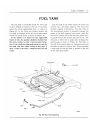
F u e l T a n k ( A l l Models Except T o w n and C o u n t r y
and I m p e r i a l )
Removal
Installation
RAM MANIFOLD
Ram Manifold -
Removal
Ram Manifold -
Installation
S e t t i n g the R a m M a n i f o l d T h r o t t l e L i n k a g e
P o s i t i o n i n g the Accelerator Shaft
P o s i t i o n i n g the Accelerator Pedal
- . -
FUEL SYSTEM —3
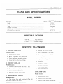
DATA AND SPECIFICATIONS
P
361 Cu. In. V-8
ENGINE
383 C u . I n . V-8
Make
-
Model
413 C u . I n . V Carter
-
M-2769S
Type
Diaphragm
N u m b e r o f Valves
Driven
By
3
.
Camshaft
P u m p Pressure (Pounds)
3% to 5
[FECIAL TOOLS
T109-43
Plug
C-3411.
Remover
Pressure Gauge
E DIAGNOSIS
1. FUEL PUMP LEAKS—FUEL
b. Leaks i n fuel line or
Possible Causes?
c.
a.
Loose housing screws,
c. Loose d i a p h r a g m m o u n t i n g plates.
e.
Frozen gas lines.
f.
I m p r o p e r l y seating valves.
g.
V a p o r lock.
h.
Weak m a i n spring.
i.
I n c o r r e c t fuel pump,
j.
Restricted fuel
fittings.
2. F U E L PUMP L E A K S — O I L
Possible Causes:
a.
D i r t or r e s t r i c t i o n i n fuel tank.
d. W o r n , r u p t u r e d , or t o r n diaphragm.
b. W o r n , r u p t u r e d or t o r n diaphragm,
d. Loose inlet or outlet line
fittings.
Cracked or deteriorated p u l l r o d oil seal.
filter.
b. Loose rocker a r m p i v o t p i n .
c. Loose p u m p m o u n t i n g bolts.
4. FUEL PUMP N O I S E
d. Defective pump t o block gasket.
Possible Causes:
3. I N S U F F I C I E N T F U E L D E L I V E R Y
a.
Loose m o u n t i n g bolts.
b.
Scored o r w o r n rocker a r m .
Possible Causes:
a. V e n t i n t a n k filler neck restricted.
also cause collapsed fuel t a n k . )
(This w i l l
c. W e a k or broken rocker a r m s p r i n g .
4 — FUEL SYSTEM
Group 14
FUEL SYSTEM
F U E L PUMP
F u e l p u m p Model M-2769S is used on a l l De Soto,
C h r y s l e r and I m p e r i a l engines. T h e service procedures f o r t e s t i n g , disassembly, overhaul, cleaning and
reassembly o f the fuel p u m p appears below.
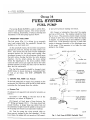
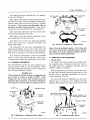
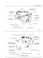
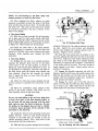
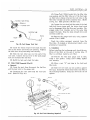
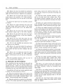
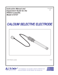
5. OPERATION—FUEL PUMP
T h e fuel p u m p ( F i g . 1) is d r i v e n b y an eccentric
cam (cast i n t e g r a l w i t h the camshaft) t h r o u g h the
m e d i u m or a s h o r t push r o d .
A s the camshaft rotates, the eccentric cam presses
against the push r o d , f o r c i n g the p u m p rocker a r m
d o w n . T h i s a c t i o n l i f t s the p u l l r o d and d i a p h r a g m
u p w a r d s against the fuel p u m p m a i n s p r i n g , t h u s
c r e a t i n g a v a c u u m i n the valve housing, w h i c h opens
the i n l e t valves, f o r c i n g fuel i n t o the valve h o u s i n g
chamber. On the r e t u r n stroke, the m a i n s p r i n g
forces the d i a p h r a g m to the d o w n p o s i t i o n w h i c h
closes the i n l e t valves and expels the fuel i n the valve
h o u s i n g chamber, t h r o u g h the outlet valve to the fuel
filter and the c a r b u r e t o r .
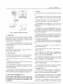
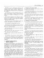
t y and a l o w pressure r e a d i n g w i l l result.
( 4 ) Connect a tachometer, t h e n s t a r t the engine
and r u n at 500 r . p . m . The r e a d i n g should be f r o m
3% t o 5 p.s.i. The pressure should r e m a i n constant
or r e t u r n to zero v e r y , v e r y slowly w h e n the engine
is stopped. A n i n s t a n t drop to zero indicates a leaky
outlet valve. I f the pressure is too low, a weak m a i n
s p r i n g or i m p r o p e r assembly of the d i a p h r a g m m a y
be the cause. I f the pressure is too h i g h , the m a i n
s p r i n g is too s t r o n g .
ROCKER ARM HOUSING
ROCKER ARM
FOLLOWER SPRING
T h e f u e l filter assembly should be changed every
10,000 miles, to i n s u r e h a v i n g a n u n r e s t r i c t e d flow
of fuel at a l l times. D O N O T A T T E M P T T O
CLEAN.
i.
— DIAPHRAGM
AND PULL ROD
ASSEMBLY
Mr
SCREW ASSEMBLY
TESTING FUEL PUMP—(On ¥ e M c l e )
I f the fuel p u m p f a i l s to s u p p l y fuel p r o p e r l y t o the
c a r b u r e t o r , the f o l l o w i n g tests should be made before
r e m o v i n g the fuel p u m p f r o m the vehicle.
VALVE-ASSEMBLY
(SERVICED ONLY
IN VALVE BODY)
VALVE B O D Y -
a. Pressure Test
SCREW ASSEMBLY
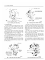
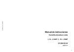
I f leakage is n o t apparent, test p u m p f o r pressure, as
follows :
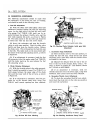
(1) I n s e r t a "T" fitting i n t h e fuel line at
c a r b u r e t o r , as s h o w n i n F i g u r e 2.
the
•1
AIR DOME \
DIAPHRAGM
( 2 ) Connect a 6 i n c h piece o f hose between t h e
" T " fitting a n d gauge C-8411. ( T h e hose should n o t
exceed 6 inches. A longer hose m a y collect f u e l and
the a d d i t i o n a l w e i g h t w o u l d be added t o the pressure
of the p u m p and r e s u l t i n a n inaccurate r e a d i n g . )
( 3 ) V e n t t h e p u m p f o r a f e w seconds ( t h i s relieves a n y a i r t r a p p e d i n the f u e l c h a m b e r ) . I f t h i s
is n o t done, the p u m p w i l l n o t operate a t f u l l capaci-
-VALVE ASSEMBLY
(SERVICED ONLY
IN VALVE BODY)
-COVER
60x189
Fig.
1 - F u e l Pump M-2769S (Exploded V i e w )
FUEL
SYSTEM
—5
a. Removal
(1)
Remove the p i v o t p i n plug, u s i n g Tool T109-
43.
TACHOMETER
(ENGINE S P E E D )
6 INCH
MAXIMUM
( 2 ) Disengage t h e rocker a r m follower s p r i n g
f r o m the rocker a r m and the r o c k e r a r m housing.
( 3 ) T u r n t h e p u m p on i t s side ( p i v o t p i n hole
d o w n ) and t a p g e n t l y t o remove t h e p i v o t p i n .
( 4 ) Disengage t h e rocker a r m f r o m the diap h r a g m p u l l r o d , b y the s l i d i n g r o c k e r a r m o u t o f
the housing.
Fig. 2—Pressure Testing Fuel P u m p
b. Vacuum Test
The v a c u u m test should be made w i t h the fuel l i n e
disconnected f r o m the c a r b u r e t o r . ( T h i s w i l l a l l o w
the p u m p t o operate at f u l l capacity, w h i c h i t m u s t
do to p r i m e a d r y c a r b u r e t o r . )
The v a c u u m r e a d i n g should be at least 10" h.g.
v a c u u m at 500 r . p . m . w i t h the fuel line disconnected
at the c a r b u r e t o r .
( 5 ) Remove t h e screws a t t a c h i n g t h e valve body
to the r o c k e r a r m housing. Separate the valve body
and r o c k e r a r m h o u s i n g and l i f t out the d i a p h r a g m
and p u l l r o d assembly.
( 6 ) Remove t h e screws t h a t a t t a c h t h e valve body
to the valve h o u s i n g cover. Separate cover and valve
body and remove the outlet a i r dome d i a p h r a g m .
b. Cleaning and Inspection
( 1 ) Clean a l l fuel p u m p p a r t s (except d i a p h r a g m )
i n a suitable solvent, t h e n b l o w d r y w i t h compressed
air.
( 2 ) Check the condition of t h e valve seats and
p a r t s f o r g u m deposits.
c. Volume Test
The fuel p u m p should supply 1 q u a r t o f fuel i n 1
m i n u t e or less at 500 r . p . m .
d. Inlet Valve Test
To test the i n l e t valve, connect a v a c u u m gauge on
the i n l e t fitting w h i l e the line is disconnected.
( 3 ) I f g u m deposits are found, remove w i t h den a t u r e d alcohol.
( 4 ) I f t h e valves are badly w o r n or damaged, i n stall a complete new valve body assembly. T h e
valves are not serviced individually.
( 1 ) S t a r t t h e engine or t u r n over w i t h s t a r t i n g
motor.
( 5 ) Inspect t h e d i a p h r a g m f o r cracks, t o r n screw
holes or r u p t u r e s . Check the r u b b e r o i l seal on the
end o f the p u l l r o d f o r d e t e r i o r a t i o n .
( 2 ) There should be a noticeable v a c u u m present,
n o t a l t e r n a t e d b y blowback.
( 6 ) Inspect the o u t l e t a i r dome d i a p h r a g m f o r
cracks or d e t e r i o r a t i o n .
( 3 ) I f blowback is present, t h e i n l e t valves are
n o t seating p r o p e r l y and should be cleaned, o r a n e w
valve body installed.
( 7 ) Inspect t h e rocker a r m f o r scoring or g a l l i n g
on the camshaft or push r o d b e a r i n g surface.
c. Assembly (Fig. 1)
I f the fuel p u m p does not p e r f o r m to the above
test requirements, the fuel p u m p should be removed
f r o m the vehicle and reconditioned as f o l l o w s :
7. FUEL PUMP DISASSEMBLY (Fig, 1)
N O T E : Before disassembling the fuel pump, mark
the housings in such a manner that the "Inlet" will
be facing the inlet fuel line when reassembled. T h i s
is important!
(1)
the
Place t h e airdome d i a p h r a g m i n p o s i t i o n on
valve body
or
filter
housing
(depending
on
p u m p ) , w i t h i n l e t passage hole over passage.
( 2 ) A l i g n t h e scribe m a r k s on t h e cover ( o r filter
housing, depending on p u m p ) a n d the valve body,
t h e n i n s t a l l a t t a c h i n g screws. T i g h t e n securely.
( 3 ) Slide the d i a p h r a g m p u l l r o d up i n t o t h e
rocker a r m housing. Place the valve body i n posi-
6 — FUEL SYSTEM
t i o n on the d i a p h r a g m w i t h the scribe m a r k s aligned.
(Be sure the holes i n the d i a p h r a g m , rocker a r m
housing and valve bodies are aligned.) Compress the
u n i t together. T h e n i n s t a l l the a t t a c h i n g screws, b u t
do not t i g h t e n . N E V E R U S E S H E L L A C OR A N Y
OTHER ADHESIVE ON T H E DIAPHRAGM,
(4) Slide t h e rocker a r m i n t o t h e housing and
gage the d i a p h r a g m p u l l r o d . A l i g n the p i v o t
holes i n the a r m w i t h those i n the housing, t h e n
s t a l l p i v o t p i n . I n s t a l l new p l u g and d r i v e i n
curely.
enpin
inse-
(5) I n s t a l l t h e rocker a r m follower s p r i n g over
the tab on the rocker a r m and over the dimple i n the
housing.
(6) Engage t h e ends of t h e bowl r e t a i n i n g strap
i n the slots of the filter housing. T i l t the r e t a i n i n g
s t r a p to one side, f a r enough to i n s t a l l the ceramic
filter.
(7) I n s t a l l a new ceramic filter, s p r i n g and bowl.
Center the b o w l , then t i g h t e n the r e t a i n i n g screw
securely.
( 8 ) Place the pump i n a vise ( w i t h protector
j a w s ) and push on the rocker a r m u n t i l f u l l t r a v e l
is reached. H o l d i n t h i s position, w h i l e t i g h t e n i n g
the a t t a c h i n g screws. ( T h i s w i l l prevent t e a r i n g
of the d i a p h r a g m w h e n the p u m p is i n operation and
the p u m p a r m i n its f u l l stroke.)
(9)
Test t h e fuel p u m p as described previously.
BBD S E R I E S C A R B U R E T O R
DATA AND SPECIFICATIONS
CARBURETOR
Type
B a l l and B a l l D u a l T h r o a t
Model
BBD-2923S or BBD-2924S
BORE
-
VENTURI
-
MAIN METERING
1-9"16"
1-5/16"
JET
Standard
N o . 120-245S
No. 120-238S
One Size L e a n
N o . 120-248S
N o . 120-248S
Two
N o . 120-250S
N o . 120-250S
Sizes L e a n
ADJUSTMENTS
F l o a t S e t t i n g ( a t center o f f l o a t s )
Accelerator P u m p (top o f p l u n g e r to a i r h o r n )
Fast Idle
9/32"
1 - f or — 1/64"
1375 to 1425 r . p . m .
F a s t Idle S e t t i n g
Choke U n l o a d e r
.015"
( w i d e open k i c k )
I d l e M i x t u r e ( b o t h screws)
I d l e Speed ( c u r b i d l e )
( w i t h air conditioning)
Bowl Vent Valve Setting
1
/
4"
1 f u l l t u r n open ±
y
2
500 r . p . m .
575 r . p . m .
.060"
CHOKE
Type
Control
Setting
Well-Automatic
Thermostatic
Coil
On I n d e x
Spring
FUEL SYSTEM —7
SPECIAL TOOLS
T109-287S
E l e v a t i n g Legs ( 3 )
T109-288S
E l e v a t i n g Legs
T109-239
F l o a t Gauge ( 9 / 3 2 " )
) P a r t of T109-289U
(1)
T109-44
W i r e Gauge (.015" F a s t I d l e )
T109-22
B e n d i n g Tool
T109-31
Choke Unloader Gauge ( % " )
.060"
D r i l l (Bowl Vent Valve)
T109-213
B e n d i n g Tool
S E R V I C E DIAGNOSIS
8. POOH IDLING
v.
I n t a k e m a n i f o l d leak,
Possible Causes:
w . I n t e r n a l coolant leak.
a.
Incorrect a i r idle adjustment.
x.
L o w b o i l i n g p o i n t fuel ( w i n t e r fuel i n s u m m e r ) .
b.
Carbonized idle tube or poor seating shoulder.
y.
L o w grade fuel.
Co M a n i f o l d heat control valve stuck.
z. I n c o r r e c t valve t i m i n g .
d.
I d l e air bleed carbonized or o f incorrect size.
e.
Idle discharge holes plugged or gummed.
f. T h r o t t l e body
shaft.
carbonized
or
worn
throttle
g . A i r leak at m o u n t i n g between carburetor and
manifold.
h.
Damaged or w o r n idle needle.
i.
I n c o r r e c t fuel or float level.
j.
Choke does n o t completely open.
k. Loose m a i n body to t h r o t t l e body screws.
1.
9. POOR PERFORMANCE—MIXTURE TOO LEAN
Possible Causes:
a.
Damaged m a i n m e t e r i n g j e t .
b. Damaged t i p or bad top shoulder seat of m a i n
discharge j e t .
c.
V a c u u m p i s t o n w o r n o r stuck,
do Incorrect fuel or float level.
e.
A u t o m a t i c choke n o t operating properly.
f.
Incorrect fuel p u m p pressure.
Carburetor i c i n g .
m. D i s t r i b u t o r advance vacuum leak.
10. POOR PERFORMANCE—MIXTURE T O O RICH
n. Loose d i s t r i b u t o r base plate bearing.
Possible Causes:
o.
Corroded w i r e ends or d i s t r i b u t o r towers.
a.
p.
Incorrect d i s t r i b u t o r p o i n t gap.
b. Excessive fuel p u m p pressure.
q.
Fouled spark plugs.
c. H i g h float or fuel level.
r.
Incorrect ignition timing.
d. Damaged needle and seat.
s.
I n c o r r e c t spark p l u g gap.
e.
L e a k i n g float.
t.
Overheated spark plugs.
f.
Worn main metering jet.
u.
Compression n o t w i t h i n l i m i t s .
g.
S t i c k i n g choke.
Restricted a i r cleaner.
8 — FUEL SYSTEM
11. E X C E S S I V E FUEL CONSUMPTION
d.
W o r n needle valve and seat.
Possible Causes:
e.
L e a k i n g float.
f.
Excessive fuel p u m p pressure.
a.
Overloading ( p u l l i n g t r a i l e r s , etc.).
b.
I m p r o p e r rear axle r a t i o .
c. W r o n g speedometer pinion.
N O T E : Presence of fuel dye around carburetor gaskets does n o t necessarily denote a leak or a flooding
condition. T i g h t e n a i r h o r n a t t a c h i n g screws securely t o correct.
d.
Brakes d r a g g i n g .
e.
Detonation or pre-ignition.
f.
D r i v i n g at excessive speeds.
g.
L o w t i r e pressure.
h.
Short t r i p or heavy traffic d r i v i n g .
i.
D r i v i n g i n snow or m u d .
j.
D r i v i n g i n high winds.
k.
Unnecessary use o f accelerator.
c. F a u l t y acceleration p u m p discharge ball.
1.
S t i c k y choke.
d.
13.
POOR ACCELERATION
Possible Causes:
a. Step-up p i s t o n stuck i n down position (lean
m i x t u r e at wide open t h r o t t l e ) .
b. Accelerator p u m p piston (or p l u n g e r ) leather
too h a r d , w o r n or loose on stem.
Accelerator p u m p i n l e t check ball f a u l t y .
m. I n c o r r e c t i g n i t i o n t i m i n g .
e. Incorrect fuel o r float level.
n.
f.
W o r n accelerator p u m p and t h r o t t l e linkage.
o. H i g h fuel level i n carburetor.
g.
A u t o m a t i c choke n o t operating properly.
p.
Stuck m a n i f o l d heat c o n t r o l valve.
h.
Carburetor gummed up.
q.
Fouled spark plugs.
i.
F a u l t y coil.
r.
L o w engine compression.
j.
Loose d i s t r i b u t o r base plate bearing.
s.
W o r n camshaft lobes.
k.
D i s t r i b u t o r n o t advancing p r o p e r l y .
t.
S t i c k i n g valves.
1.
Incorrect ignition timing.
u.
E l e v a t i o n and atmospheric conditions.
m. I n c o r r e c t spark p l u g gap.
I n c o r r e c t d i s t r i b u t o r advance.
v. Restricted t a i l pipe or muffler causing exhaust
back pressure.
w. I n c o r r e c t valve t i m i n g .
12.
CARBURETOR FLOODS OR LEAKS
Possible Causes:
n.
Fouled spark plugs.
o. Overheated spark plugs.
p.
M a n i f o l d heat control valve stuck.
q.
L o w fuel pump pressure or vacuum.
r.
Compression n o t up t o specifications.
a.
Cracked body.
s.
L o w grade of fuel.
b.
Defective body gaskets.
t.
D e t o n a t i o n or p r e - i g n i t i o n .
u.
I n c o r r e c t valve t i m i n g .
c. H i g h float or fuel level.
FUEL SYSTEM — 9
C A R B U R E T O R MODELS
BBD-2923S OR BBD-2924S
14. SERVICING THE
CARBURETOR
D i r t , dust, w a t e r and g u m m y deposits are some of
the m a i n causes f o r poor c a r b u r e t o r operation.
P r o p e r cleaning, however, and i n s t a l l a t i o n of new
p a r t s , where required, w i l l r e t u r n the c a r b u r e t o r
to its o r i g i n a l l y designed performance.
W h e n o v e r h a u l i n g the carburetor, several items
of i m p o r t a n c e should be observed to assure a good
j o b . A l l p a r t s should be carefully cleaned i n a suitable solvent and inspected f o r damage and wear.
Replace questionable p a r t s w i t h N E W ones.
Use a i r pressure only, to clear the various orifices
and passages.
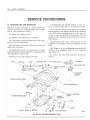
SERVICE PROCEDURES
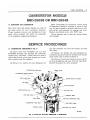
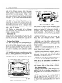
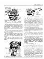
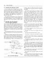
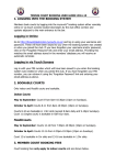
15. CARBURETOR DISASSEMBLY (Fig. 3)
( 1 ) I n s e r t t h r e e Tool T109-287S and one Tool
T109-288S elevating legs t h r o u g h the c a r b u r e t o r
t h r o t t l e body stud holes. (These tools are used to
protect the t h r o t t l e valves f r o m damage and to p r o vide a suitable base f o r w o r k i n g . )
( 2 ) Remove the
h a i r p i n clip and
disengage
ACCELERATOR PUMP ARM
the
fast idle connector r o d f r o m the t h r o t t l e and
idle levers.
( 3 ) Remove the h a i r p i n clip and disengage the
accelerator p u m p r o d f r o m the t h r o t t l e lever and the
p u m p rocker a r m , as shown i n F i g u r e 4.
( 4 ) Remove t h e a i r h o r n r e t a i n i n g screws and l i f t
a i r h o r n s t r a i g h t up and a w a y f r o m the m a i n body.
D i s c a r d the gasket (2 screws recessed).
CHOKE VALVE
ACCELERATOR PUMP PLUNGER
BOWL VENT SEAL
CHOKE PISTON CYLINDER
AIR HORN
FAST IDLE SCREW
IDENTIFICATION TAG
FAST IDLE CAM
FAST IDLE LEVER -
. THROTTLE BODY
MAIN BODY
ACCELERATOR
PUMP ROD <
THROTTLE LEVER .
fast
FAST IDLE CONNECTOR
ROD
IDLE SPEED SCREW
ELEVATING LEG (TOOL)
58x240B
Fig. 3—Carburetor Assembly BBD-2923S or BBD-2924S
10 —FUEL SYSTEM
—FLOAT
STEP UP PISTON
.ACCELERATOR PUMP
CONNECTOR ROD
J
•IS
FAST IDLE
C O N N E C T O R ROD
/
CENTER HOLE
GASKET
"i
HAIRPIN C U P
58x241A
Fig. 4—Removing ©r Installing Fast Idle a n d
Pump Rods
( 5 ) Disengage t h e accelerator p u m p plunger f r o m
the accelerator p u m p a r m b y p u s h i n g up on b o t t o m
of p l u n g e r a n d s l i d i n g p l u n g e r shaft off hook, as
s h o w n i n F i g u r e 5. Slide p l u n g e r o u t o f a i r h o r n
and remove the compression s p r i n g a n d seat.
I f the old p l u n g e r can be used a g a i n o r i f a n e w
p l u n g e r is t o be installed, place t h e p l u n g e r i n a
j a r o f clean gasoline o r kerosene t o p r e v e n t t h e leather f r o m d r y i n g out.
_ _ NEEDLE
Ox*— V A L V E
r
111
w
58x242 A
Fig. 6—Removing or Installing Float
w e l l , as shown i n F i g u r e 7. L i f t out t h e step-up
p i s t o n s p r i n g . Remove the step-up p i s t o n gasket
f r o m the b o t t o m o f t h e w e l l .
STEP-UP PISTON
STEP-UP RODS
STEP-UP PISTON
SPRING
MAIN
' METERING
JETS
( 6 ) Remove t h e fuel i n l e t needle valve, seat and
gasket f r o m t h e m a i n body.
( 7 ) L i f t out t h e float f u l c r u m p i n retainer, and
l i f t out the floats a n d f u l c r u m p i n , as s h o w n i n
F i g u r e 6.
( 8 ) Remove t h e step-up p i s t o n and r e t a i n i n g
screw a n d slide the step-up p i s t o n a n d rods o u t o f
R E T A I N I N G SCREW
60x102
ACCELERATOR
PUMP SHAFT
ACCELERATOR
PUMP ARM
Fig. 7—Removing
m Girnsira.ling Step-Up Piston
SPECIAL TOOL
C H O K E PISTON
LINK
CHOKE
PISTON
PLUG
58x246A
Fig. 5—Removing
or Installing Accelerator Pump
MAIN
METERING JET
>
58x244A
Fig. 8—Removing or Installing Main Metering Jets
FUEL
(9) Remove t h e m a i n m e t e r i n g j e t s a n d gaskets,
as shown i n F i g u r e 8.
SPARK
IDLE T R A N S F E R PORTS
A
(10) Remove the v e n t u r i cluster idle bleed screws,
t h e n l i f t t h e v e n t u r i cluster and gaskets up and away
f r o m t h e m a i n body, as shown i n F i g u r e 9. Discard
the gaskets. Do not remove the idle orifice tubes or
the main vent tubes from the cluster. T h e y can be
cleaned i n a solvent and d r i e d w i t h compressed air.
(11) I n v e r t t h e c a r b u r e t o r and drop o u t t h e accelerator p u m p discharge check ball.
- \
IDLE
16. CLEANING C A I B U R E T O I
The recommended solvent f o r g u m deposits is den a t u r e d alcohol w h i c h is easily obtainable. There
are other commercial solvents, however, w h i c h m a y
be used w i t h satisfactory results.
IMPORTANT
I f the commercial solvent or cleaner recommends the
use of water as a rinse, it should be " H O T . " After
rinsing, all trace of water must be blown from the
passages with air pressure. I t is further advisable to
rinse all parts in clean kerosene or gasoline to be cer-
Fig.
9 - R e m o v i n g or Installing Venturi Cluster
ADVANCE
PORT
/
IDLE M I X T U R E
VALVES
SCREWS
SPEED
r
SCREW
(13) Remove t h e screws t h a t a t t a c h t h e t h r o t t l e
body to the m a i n body. Separate the bodies and
discard the gasket.
I t is usually not advisable to remove the t h r o t t l e
shaft or valves f r o m the t h r o t t l e body, unless wear
or damage necessitates the i n s t a l l a t i o n o f new parts.
V
THROTTLE
(12) Remove t h e idle m i x t u r e a d j u s t i n g screws
and springs f r o m the t h r o t t l e body.
The c a r b u r e t o r n o w has been disassembled i n t o
three sub-assemblies, the a i r h o r n , m a i n body and
t h r o t t l e body and the components of each disassembled as f a r as necessary f o r cleaning and inspection.
SYSTEM—11
.1'
Fig.
- GASKET
^-
60x104
1 0 — P o r t s in Relation to Throttle V a l v e s
tain no trace of moisture remains. Never clean jets
with a wire, drill or other mechanical means, because
the orifices may become enlarged, making the mixture too rich for proper performance.
17.
INSPECTION A N D 1EASSEMBLY
a. Throttle Body
(1) Inspect t h e t h r o t t l e shaft and t h r o t t l e body
for excessive wear. I f either or b o t h are w o r n t o
the p o i n t w h e r e the c a r b u r e t o r operation w i l l be
affected, replace as r e q u i r e d .
D u r i n g m a n u f a c t u r e , the location of the idle t r a n s fer p o r t and the spark advance c o n t r o l p o r t s t o t h e
t h r o t t l e valve, is carefully established f o r one p a r t i c u l a r assembly ( F i g . 1 0 ) .
I f a new shaft should be installed i n an old, w o r n
t h r o t t l e body, i t w o u l d be v e r y u n l i k e l y t h a t the
o r i g i n a l r e l a t i o n s h i p of the p o r t s to the valves w o u l d
Fig. 1 1-lnstalling Throttle V a l v e s
12 — F U E L
SYSTEM
be obtained. C h a n g i n g the relationship o f the valves
t o the p o r t s w o u l d adversely affect n o r m a l car opera t i o n between the speeds o f 15 and 30 miles per h o u r .
I f i t has been determined, however, t h a t a new shaft
o r valves is to be installed, adhere to the f o l l o w i n g
instructions.
( 2 ) M a r k t h e p o s i t i o n o f t h e t h r o t t l e valves i n t h e
bores. Be sure the i d l e speed screw is backed off.
( 3 ) Remove t h e screws t h a t hold t h e t h r o t t l e
valves t o the shaft and slide the valves out o f the
bores.
CAUTION
These screws are staked on the opposite side and care
should be used a t r e m o v a l so as n o t t o .break off i n
the shaft.
( 4 ) Slide t h e t h r o t t l e shaft and lever out o f t h e
body.
( 5 ) I n s t a l l new t h r o t t l e shaft and lever.
( 6 ) I n s t a l l t h r o t t l e valves i n t h e i r respective bores
( w i t h the valve numbers t o w a r d the m a n i f o l d
flange). I n s t a l l new screws b u t do n o t t i g h t e n . H o l d
the valves i n place, w i t h the fingers pressing on the
h i g h sides o f the valves, as shown i n F i g u r e 1 1 .
T a p the valves l i g h t l y w i t h a s c r e w d r i v e r t o seat
i n the t h r o t t l e bores. T i g h t e n the screws securely
and stake b y squeezing w i t h p l i e r s .
( 7 ) I n s t a l l t h e idle m i x t u r e screws and springs
i n the t h r o t t l e body. ( T h e tapered p o r t i o n m u s t be
s t r a i g h t a n d smooth. I f the tapered p o r t i o n is
grooved or r i d g e d , new idle m i x t u r e screws should
be i n s t a l l e d to insure h a v i n g correct idle m i x t u r e
control.) D O N O T U S E A S C R E W D R I V E R . T u r n
STEP-UP RODS MUST MOVE FREELY
60x106
Fig. 13—Step-Up Rod Free Play
t h e screws l i g h t l y against t h e i r seats w i t h t h e fingers.
Back off one f u l l t u r n f o r approximate adjustment.
b. Main Body
(1) I n v e r t the m a i n body and place a new gasket
i n p o s i t i o n and place the t h r o t t l e body on the m a i n
body and a l i g n . I n s t a l l screws and t i g h t e n securely.
( 2 ) I n s t a l l t h e accelerator p u m p discharge check
b a l l i n the discharge passage and check the accelera t o r p u m p system; fuel i n l e t and discharge check
balls as f o l l o w s :
( 3 ) Pour clean gasoline i n t o t h e carburetor bowl,
a p p r o x i m a t e l y / i n c h deep. Remove the p u m p
p l u n g e r f r o m the j a r o f gasoline, flex the leather
several times, t h e n slide d o w n i n t o the p u m p c y l i n der. Raise the p l u n g e r and press l i g h t l y on the
p l u n g e r shaft to expel a l l a i r f r o m the p u m p
passage.
l
2
( 4 ) U s i n g a s m a l l clean brass r o d , hold t h e discharge check b a l l d o w n f i r m l y on i t s seat. A g a i n
raise the p l u n g e r and press d o w n w a r d . N o fuel
should be e m i t t e d f r o m either the i n t a k e o r discharge passage, as shown i n F i g u r e 12.
I f any fuel does e m i t f r o m either passage, i t i n d i cates the presence o f d i r t o r a damaged check b a l l .
Check the passage again and repeat test. I f leakage is s t i l l evident, i n s t a l l a new check ball. The
fuel i n l e t check b a l l is located a t the b o t t o m o f the
p l u n g e r w e l l and should r a t t l e freely w h e n the
carburetor is shaken.
58x249B
Fig. 12—Testing Accelerator Pump Intake a n d
Discharge Check Balls
( 5 ) I n s t a l l new gaskets on t h e v e n t u r i cluster, and
i n s t a l l i n p o s i t i o n i n the m a i n body. (Refer t o F i g .
9 ) . I n s t a l l the idle bleed screws and t i g h t e n securel y . Test p u m p discharge b y pressing p u m p p l u n g e r
FUEL SYSTEM— 13
d o w n . T w o fine streams o f fuel should be forced
f r o m the cluster. I f e i t h e r s t r e a m is r e s t r i c t e d or
d i v e r t e d , remove cluster and reclean. A f t e r test,
p o u r the f u e l f r o m the b o w l and remove p u m p
plunger.
( 6 ) I n s t a l l t h e m a i n m e t e r i n g j e t s and gaskets.
T i g h t e n securely. (Refer to F i g . 8 ) .
( 7 ) Before i n s t a l l i n g t h e step-up piston, be sure
the step-up rods are able to move freely, each side
of the v e r t i c a l p o s i t i o n , as shown i n F i g u r e 13. The
step-up rods m u s t be s t r a i g h t and smooth.
FROM TOP O F
PUMP SHAFT TO
BOTTOM O F
AIR HORN
( 8 ) Slide t h e step-up p i s t o n gasket d o w n i n t o posit i o n i n the p i s t o n w e l l , t h e n i n s t a l l the step-up p i s t o n
s p r i n g , step-up p i s t o n and rods. C a r e f u l l y guide
t h e step-up rods i n t o the m a i n m e t e r i n g j e t s . (Refer
to F i g . 7 ) . I n s t a l l the r e t a i n i n g screw and t i g h t e n
securely. Check p i s t o n f o r free operation i n the
well.
THROTTLE VALVES SEATED ^ 3 . , .
A step-up p i s t o n stuck i n the U p p o s i t i o n w i l l
cause a r i c h m i x t u r e a t p a r t t h r o t t l e , whereas a
p i s t o n stuck i n the D o w n p o s i t i o n w i l l cause a lean
m i x t u r e at w i d e open t h r o t t l e and poor acceleration.
c. Checking Float Setting
(1)
I n s t a l l t h e floats and f u l c r u m p i n .
( 2 ) Assemble t h e fuel inlet needle valve, seat and
gasket a n d i n s e r t i n p o s i t i o n i n the m a i n body.
T i g h t e n securely. ( I f the needle valve is r i d g e d or
b a d l y w o r n , i n s t a l l a new needle valve and seat
assembly.)
( 3 ) U s i n g Tool T109-239 or a " T " scale, check t h e
float s e t t i n g , as shown i n F i g u r e 14. There should
be 9 / 3 2 " f r o m top o f the c r o w n o f each float t o t o p
FLOAT UP HELD AGAINST
NEEDLE VALVE
^
%^
^
^^^^^^
\
FLOAT G A U G E
60x107
71
4—Checking
FAST IDLE
SCREW O F F
FAST IDLE
CAM
58x255B
Fig.
15—Measuring Accelerator Pump Travel
of the m a i n body. E a c h float m u s t be adjusted t o
t h i s s e t t i n g a n d should not touch the sides o f the
b o w l . I n s t a l l float f u l c r u m p i n r e t a i n e r .
d. A i r Horn
( 1 ) Check the freedom o f t h e choke mechanism i n
the a i r h o r n . The shaft and p i s t o n m u s t float free
to operate c o r r e c t l y . I f the choke p i s t o n sticks i n
the c y l i n d e r , pierce the welsh p l u g and remove p l u g
and p i s t o n . Clean t h o r o u g h l y a n d r e i n s t a l l p i s t o n .
I n s t a l l new p l u g .
( 2 ) Remove accelerator p u m p p l u n g e r f r o m gasoline, slide compression s p r i n g and s p r i n g seat over
shaft. I n s t a l l assembly i n a i r h o r n a n d engage w i t h
accelerator p u m p a r m . (Refer t o F i g . 5 ) .
(3) Place a new gasket on t h e m a i n body, and i n s t a l l the a i r h o r n . I n s t a l l a t t a c h i n g screws and
t i g h t e n securely. ( W h e n i n s t a l l i n g a i r h o r n , be sure
the leather on the p l u n g e r does n o t w r i n k l e or f o l d
back.)
(4) Engage t h e accelerator p u m p r o d w i t h t h e
p u m p rocker a r m and i n s t a l l loose end i n the center
hole o f t h r o t t l e lever. (Refer t o F i g . 4 ) . I n s t a l l
h a i r p i n clip to secure.
•
Fig.
§
¥l©at
Setting
( 5 ) Engage the f a s t idle connector r o d i n t h e fast
idle lever and t h r o t t l e lever. I n s t a l l h a i r p i n clip t o
secure. (Refer t o F i g . 4.)
18. CABBURETOl ADJUSTMENTS
I t is v e r y i m p o r t a n t t h a t the f o l l o w i n g adjustments
are made on a reconditioned c a r b u r e t o r and i n the
sequence l i s t e d :
14 —FUEL SYSTEM
. UNLOADER
GAUGE
iHROTTLE VALVE
b#lf
LIGHT FINGER PRESSURE
' A G A I N S T CHOKE VALVE
T i l
THROTTLE VALVES IN
WIDE OPEN POSITION
^ ^ ^ ^ ^ ^ ^ ' ' . ^ ^ FAST IDLE C A M
\
INDEX MARK
FAST IDLE ADJUSTING S C R E W
58x252 A
58x254B
Fig. 16—Checking Fast Idle Setting
Fig. 18—Checking Choke Unloader Setting
a. Accelerator Pump
(1) Back off t h e idle speed a d j u s t i n g screw. Open
the choke valve so t h a t the t h r o t t l e valves can be
completely seated i n the bores. Be sure t h a t the
p u m p connector r o d is i n s t a l l e d i n the center hole
of the t h r o t t l e lever.
( 2 ) H o l d i n t h i s position, and i n v e r t t h e carburet o r . Slide w i r e gauge Tool T109-44 .015" between t h e
t h r o t t l e valves and the bore (side opposite p o r t s ) .
T i g h t e n the fast idle a d j u s t i n g screw u n t i l a s l i g h t
d r a g is f e l t as gauge is b e i n g w i t h d r a w n , as shown
i n F i g u r e 16.
( 2 ) Close t h e t h r o t t l e valves t i g h t l y . Measure t h e
distance between the top o f t h e a i r h o r n and the
end o f p l u n g e r shaft, as s h o w n i n F i g u r e 15. T h i s
measurement should be 1 " ± o r — 1/64 i n c h .
( 3 ) A g a i n , i n v e r t t h e carburetor a n d open t h e
valves to w i d e open position. Close the t h r o t t l e
valves and the choke valve t i g h t l y .
( 3 ) To adjust p u m p t r a v e l , bend t h e p u m p connector r o d , u s i n g Tool T109-213, a t t h e l o w e r angle
of r o d , u n t i l correct t r a v e l has been obtained.
( 4 ) Release t h e choke valve only. T h i s again posit i o n s the f a s t idle cam to fast idle. The i n d e x m a r k
on the cam should s p l i t the center o f the f a s t idle
screw shank, as shown i n F i g u r e 17.
b. Fast Idle Adjustment
(1) Open t h e t h r o t t l e valves and hold t h e choke
valve i n the f u l l y closed p o s i t i o n . Close t h e t h r o t t l e
valves. T h i s w i l l p o s i t i o n the f a s t idle cam t o the
fast idle p o s i t i o n .
I f an adjustment is necessary, bend the t a n g on
the choke shaft lever, u s i n g Tool T109-22 u n t i l the
i n d e x m a r k on the cam indexes w i t h the a d j u s t i n g
screw.
INDEX MARK
58x253B
Fig. 17—Fast Idle Index Mark A l i g n e d
•
-
~
58x256B
Fig. 19—Bending Fast Idle Lever Tang
FUEL SYSTEM—15
c. Choke Unloader (wide open kick)
( 1 ) H o l d t h e t h r o t t l e valves i n t h e wide open posit i o n . I n s e r t Tool T109-31 ( o r a
d r i l l shank)
between the upper edge o f the choke valve and the
i n n e r w a l l of the a i r h o r n , as shown i n F i g u r e
18.
( 2 ) W i t h a finger l i g h t l y pressing against t h e
valve, a s l i g h t d r a g should be f e l t as gauge is b e i n g
w i t h d r a w n . I f an a d j u s t m e n t is necessary, bend the
t a n g on the fast idle lever, u s i n g Tool T109-22, as
shown i n F i g u r e 19 u n t i l correct clearance has been
obtained.
C H O K E ROD
DUST S E A L WASHER
COVER
CALIBRATION
IOCK
M A R K S \
NUT
d. Bowl Vent Valve Adjustment
( 1 ) W i t h the t h r o t t l e valves held closely, i t should
be possible to i n s e r t a .060" d r i l l shank between the
b o w l vent valve and the a i r h o r n .
(2) I f an adjustment is necessary, bend t h e short
t a n g on the vent valve o p e r a t i n g lever, u s i n g Tool
T109-22 u n t i l correct clearance has been obtained.
e. Idle Speed Adjustment (curb idle)
The idle speed a d j u s t m e n t is made after the
b u r e t o r has been installed on the engine.
THERMOSTATIC C O I L ^ J ^ t ^
SPRING AND H O U S I N G
'
-INDEX MARK
57P55
Fig. 20—Well Type Automatic Choke Unit
be clean and move freely. O t h e r t h a n an occasional
cleaning, the choke requires no s e r v i c i n g . I t is v e r y
i m p o r t a n t , however, t h a t t h e choke c o n t r o l u n i t
w o r k freely i n the w e l l and at the choke shaft.
car-
( 1 ) W i t h the t h r o t t l e valves closed and t h e choke
valve w i d e open (engine at n o r m a l o p e r a t i n g t e m p e r a t u r e ) adjust the idle speed screw to give 500
r . p . m . u s i n g a tachometer, (575 r . p . m . on a i r condit i o n equipped c a r s ) .
( 2 ) A d j u s t the idle m i x t u r e screws u n t i l the engine operates smoothly. Recheck the tachometer
and again adjust the idle screw to give the correct
engine r . p . m .
19. AUTOMATIC C H O K E — W E L L TYPE
To f u n c t i o n p r o p e r l y , i t is i m p o r t a n t t h a t a l l p a r t s
Move the choke
movement on the
choke u n i t should
C H O K E U N I T is
a t t e m p t to r e p a i r
F i g . 20.)
r o d up and d o w n to check f o r free
p i v o t . I f the u n i t binds, a new
be installed. T H E W E L L T Y P E
serviced as an assembly. D o n o t
or change the index s e t t i n g . (See
W h e n i n s t a l l i n g the w e l l t y p e choke u n i t , be cert a i n t h a t the coil h o u s i n g does not contact the sides
of the w e l l i n the i n t a k e m a n i f o l d . A n y contact at
t h i s p o i n t w i l l affect choke operation.
D o not l u b r i c a t e any p a r t s o f the choke or the cont r o l u n i t . T h i s causes an accumulation o f d i r t w h i c h
w i l l result i n b i n d i n g of the choke mechanism.
16 — FUEL SYSTEM
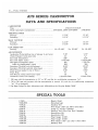
AFB S E R I E S CARBURETOR
DATA AND SPECIFICATIONS
CARBURETOR
Type
Model (automatic t r a n s m i s s i o n )
4 Barrel Downdraft
AFB-2927S, 2950S AFB-2968S
AFB-2903S
T H R O T T L E BORE
Primary
Secondary
MAIN VENTURI
Primary
Secondary
LOW SPEED
Primary
.
.
1-7/16"
1-11/16"
1-3/16"
1-5/16"
1-3/16"
1-9/16"
JET
No. 67-.032"
ADJUSTMENTS
Accelerator P u m p S e t t i n g (top of plunger to a i r h o r n )
Choke Unloader ( w i d e open k i c k )
F a s t Idle A d j u s t m e n t
F a s t Idle Speed ( r p m )
Idle Speed A d j u s t m e n t ( r p m )
( w i t h air conditioning) ( r p m )
Secondary T h r o t t l e Lever A d j u s t m e n t
Secondary T h r o t t l e Lock-Out A d j u s t m e n t
F l o a t S e t t i n g (gasket to top of
floats)
Float Drop
Idle M i x t u r e ( b o t h screws-turns open)
A u t o m a t i c Choke U n i t S e t t i n g
*
1-7/16"
1-9/16"
N o . 67-.035"
7/16"
y±"
.020"
1775-1825
500
550*
19/64"
.020"
7/32"
%"
1-2
2 Notches R i c h
N o . 65-.035"
7/16"
A "
.010"
***1475-1525
**725-750
*550
19/64"
.020"
9/32"
%"
1-2
1 Notch Rich
l
550 r p m w i t h the transmission i n " D " or " R " and the a i r c o n d i t i o n i n g compressor " o n " .
** 725 to 750 r p m and constant w i t h the t r a n s m i s s i o n i n n e u t r a l ( N ) and the a i r c o n d i t i o n i n g compressor
" o n " ( i f so equipped).
***On R a m Charge De Soto A d v e n t u r e r and 1375-1425 on the Chrysler Model C300F.
S P E C I A L TOOLS
C-3400
T109-287S
T109-22
T109-29....
T109-31
T109-41
T109-58
T109-59
T109-106
T109-126
T109-200
T109-213
...
.
R e p a i r Stand
E l e v a t i n g Legs
B e n d i n g Tool
W i r e Gauge (.020" and .030") ( F a s t I d l e )
.Gauge
(Choke U n l o a d e r )
B e n d i n g Tool ( F a s t Idle E n d U n l o a d e r )
Screwdriver B i t
Screwdriver B i t
F l o a t Gauge ( 7 / 3 2 " )
.Float Gauge ( 9 / 3 2 " )
W i r e Gauge (.010" and .012") ( F a s t I d l e )
B e n d i n g Tool
FUEL SYSTEM—17
CHOKE VALVE
STEP-UP PISTON A N D
58x275 A
STEP-UP PISTON AND ROD COVER PLATE (2)
CHOKE
PISTON LINK
ACCELERATOR PUMP
CONNECTOR LINK
FUEL INLET C O N N E C T I O N
-f-V ACCELERATOR PUMP
SHAFT
MODEL NUMBER AND DATE
STAMPED O N BOSS
(AT CENTER O F CARBURETOR)
SECONDARY THROTTLE
OPERATING LEVER
.
^JLT,
*~
7
PUMP C O N N E C T O R
ROD IN CENTER
HOLE O F ARM
/
PRIMARY THROTTLE
SHAFT ARM (OUTER)
DISTRIBUTOR VACUUM FITTING
THROTTLE OPERATING ROD
PRIMARY THROTTLE SHAFT ARM (INNER)
PRIMARY THROTTLE SHAFT D O G
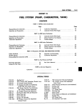
Fig. 21—Carburetor A s s e m b l y
58x276 A
18 — F U E L SYSTEM
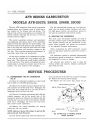
AFB SERIES CARBURETOR
MODELS AFB-2927S, 2950S, 2968S, 2903S
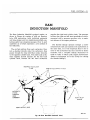
The new A F B ( a l u m i n u m f o u r b a r r e l ) c a r b u r e t o r
contains m a n y new features, some o f w h i c h are a
new location f o r the step-up rods and pistons. The
step-up rods, pistons and springs are accessible f o r
service w i t h o u t r e m o v i n g the a i r h o r n , o r the carb u r e t o r f r o m the engine.
The v e n t u r i assemblies ( p r i m a r y and secondary)
are replaceable and contain m a n y o f the c a l i b r a t i o n
points f o r b o t h the h i g h and l o w speed system. One
fuel b o w l feeds b o t h the p r i m a r y and secondary nozzles on the r i g h t side w h i l e the other fuel b o w l takes
care o f the p r i m a r y and secondary nozzles on the
left side. T h i s provides i m p r o v e d performance i n
c o r n e r i n g , quick stops and acceleration.
A l l the m a j o r castings of the c a r b u r e t o r are a l u m i n u m , w i t h the t h r o t t l e body cast i n t e g r a l w i t h the
m a i n body. T h i s allows an overall h e i g h t r e d u c t i o n
i n the carburetor. The section c o n t a i n i n g the accele r a t o r p u m p is t e r m e d the p r i m a r y side o f the carb u r e t o r . The rear section is the secondary.
The five conventional systems are t w o float systems, t w o l o w speed systems ( p r i m a r y side o n l y ) ,
t w o h i g h speed systems, one accelerator p u m p syst e m and one automatic choke control system.
20. SERVICING THE CARBURETOR
D i r t , dust, w a t e r and g u m m y deposits are some of
the m a i n causes f o r poor carburetor operation. H o w ever, proper cleaning and the i n s t a l l a t i o n of new
parts, w h e r e required, w i l l r e t u r n the carburetor
to i t s o r i g i n a l l y designed performance.
W h e n o v e r h a u l i n g the A F B carburetor, several
items o f importance should be observed to assure a
good j o b .
The c a r b u r e t o r should be carefully disassembled
and a l l p a r t s should be cleaned i n a suitable solvent
and inspected f o r wear or damage.
A i r pressure only should be used to clean the
v a r i o u s orifices and channels. Replace questionable
p a r t s w i t h new ones.
SERVICE PROCEDURES
2 1 . DISASSEMBLING THE AFB CARBURETOR
(Fig. 21)
tons and rods out of the a i r h o r n , as shown i n F i g u r e
22. Remove the step-up p i s t o n springs.
( 1 ) Place t h e c a r b u r e t o r assembly o n repair stand
Tool C-3400 or T-109-287S e l e v a t i n g legs.
( 6 ) Remove t h e ten screws t h a t attach the a i r
STEP-UP PISTON AND ROD
( 2 ) Remove t h e h a i r p i n clip t h a t attaches the f a s t
idle connector r o d to the choke lever. Disengage r o d
f r o m lever, t h e n s w i n g r o d at a n arc u n t i l i t can be
disengaged f r o m the fast idle cam.
STEP-UP PISTON SPRING
( 3 ) Remove t h e retainer and s p r i n g t h a t holds t h e
t h r o t t l e connector r o d i n the center hole o f t h e
accelerator p u m p a r m . Remove the h a i r p i n clip t h a t
attaches the l o w e r end o f r o d i n the p r i m a r y t h r o t t l e
shaft lever. Disengage r o d f r o m a r m and lever,
t h e n remove f r o m c a r b u r e t o r .
( 4 ) Remove the screws a t t a c h i n g
p i s t o n and r o d cover plates.
the
step-up
N O T E : H o l d c o v e r d o w n w i t h a finger to p r e v e n t t h e
p i s t o n a n d r o d s f r o m flying o u t .
(5) L i f t off the plates and slide the step-up pis-
COVER PLATES 58x277
-~
STEP-UP PISTON
r
\
STEP-UP ROD
Fig. 22—Removing or Installing Step-Up
Pistons a n d Rods
FUEL
h o r n to the m a i n body ( 1 screw i n hole i n a i r h o r n ) .
L i f t a i r h o r n s t r a i g h t up and a w a y f r o m the m a i n
body.
N O T E : W h e n r e m o v i n g a i r h o r n , u s e c a r e so a s n o t
to bend o r d a m a g e t h e floats.
( 7 ) Remove t h e accelerator p u m p plunger lower
s p r i n g f r o m the p u m p c y l i n d e r .
SYSTEM—19
PRIMARY VENTURI
( C H O K E SIDE)
SECONDARY
VENTURI
(CHOKE SIDE)
PRIMARY
VFNTURI
(PUMP S I D E )
.
SECONDARY
VFNTURI
(PUMP SIDE)
^ '*
a. Disassembling the A i r Horn
Place the a i r h o r n i n an i n v e r t e d p o s i t i o n on the
bench (to p r o t e c t the floats).
(1) U s i n g a suitable tool, remove t h e float f u l c r u m
pins (left and r i g h t ) and l i f t t h e floats up and out
of bosses on a i r h o r n .
N O T E : I t i s s u g g e s t e d t h a t t h e float o n t h e p u m p
side be m a r k e d s o t h a t t h e floats c a n be r e - i n s t a l l e d
in their respective positions.
( 2 ) Remove t h e t w o needle valves f r o m t h e i r respective seats, a f t e r m a r k i n g the one on the p u m p
side f o r identification. U s i n g a w i d e blade screwd r i v e r , remove the needle valve seats. Be sure each
needle valve is r e t u r n e d t o i t s o r i g i n a l seat at reassembly.
( 3 ) Remove the h a i r p i n clip t h a t holds the accele r a t o r p u m p connector l i n k i n the p u m p a r m and
p l u n g e r shaft. Disengage l i n k f r o m p u m p a r m a n d
shaft.
Slide the accelerator p u m p p l u n g e r and
s p r i n g out o f the a i r h o r n . Remove the a i r h o r n t o
m a i n body gasket and discard.
( 4 ) Place the accelerator p u m p plunger i n a j a r
of clean gasoline or kerosene, to p r e v e n t the leather
f r o m d r y i n g out.
( 5 ) Remove t h e fuel i n l e t fitting and filter screen
f r o m the a i r h o r n .
DISCHARGE CHECK
NEEDLE (IN HOLE)
ACCELERATOR / PUMP CYLINDER
' ''
|L
l\
f*;
f%lf^^W
y
S E C O N D A R Y JET (2)
A PRIMARY J E T (2)
58*2/8
Fig. 24—Removing or Installing Main Metering Jets
( 6 ) U s i n g a p r i c k punch, pierce t h e welch p l u g
and remove i t f r o m the end o f choke p i s t o n c y l i n d e r .
Remove cotter p i n t h a t attaches the p i s t o n l i n k t o
the choke valve lever. Slide choke p i s t o n and l i n k
out o f cylinder.
b. M a i n B o d y D i s a s s e m b l y
(1) Remove t h e screws t h a t a t t a c h the accelerat o r p u m p j e t h o u s i n g to the m a i n body. L i f t out the
j e t housing and gasket, as shown i n F i g u r e 23.
D i s c a r d the gasket. I n v e r t the m a i n body and d r o p
out the discharge check needle f r o m the discharge
passage.
( 2 ) U s i n g Tool T109-58, remove t h e m a i n meteri n g jets ( p r i m a r y side), as shown i n F i g u r e 24.
N O T E : T h e p r i m a r y and secondary main metering
j e t s a r e not interchangeable.
I t is very important
t h a t t h e s e j e t s be i n s t a l l e d i n t h e i r r e s p e c t i v e locat i o n s i n t h e m a i n body a t r e a s s e m b l y .
GASKET
PRIMARY VENTURI (PUMP SIDE)
h?IMAKY VENTURI
C H O K E SIDE
/
/
'4 si-
MODEL NUMBER
A N D DATE
STAMPED
O N BOSS
<**
• 'f '
A
58x283
Fig. 23—Removing or Installing Accelerator
P u m p Jet Housing
Fig. 25—Removing or Installing Primary Venturi
20 — FUEL SYSTEM
SECONDARY VENTURI PUMP SIDE
GASKET
PUMP JET HOUSING
^
SECONDARY VENTURI
(CHOKE SIDE)
y
h
IDLE DISCHARGE PORTS
PRIMARY
THROTTLE
VALVES
ACCELERATOR
PUMP INTAKE
PASSAGE
CHOKE SIDE OF
CARBURETOR
PUMP SIDE OF CARBURETOR
SECONDARY VENTUF
NOZZLE BLEEDER TUBE
PRIMARY VENTURI
^
( 5 ) Remove the screws t h a t attach the secondary
v e n t u r i (choke and p u m p side) to the m a i n body.
L i f t the secondary v e n t u r i assemblies s t r a i g h t up
and away f r o m the body, as shown i n F i g u r e 26.
NOZZLE
\
BLEEDER TUBE
DO NOT REMOVE TUBES R O M
VENTURI
58x284
Fig. 26—Removing or Installing Secondary Venturi
( 3 ) A g a i n using Tool T109-58, remove the m a i n
m e t e r i n g jets (secondary side), as shown i n F i g u r e
24.
( 4 ) Remove the screws
v e n t u r i (choke and p u m p
L i f t the v e n t u r i s t r a i g h t
m a i n body, as shown i n
gaskets.
t h a t a t t a c h the p r i m a r y
side) to the m a i n body.
up and a w a y f r o m the
F i g u r e 25. D i s c a r d the
N O T E : The v e n t u r i assemblies are not interchangeable, side f o r side and m u s t be re-installed i n t h e i r
o r i g i n a l location a t reassembly.
VA INCH BIT
CHECK BALL SEAT
PLUG
^
58x287
Fig. 28—Ports in Relation to Throttle V a l v e s
MAIN BLEED TUBE %
IDLE TUBE
IDLE TRANSFER PORTS
58x286
Fig. 27—Removing or Installing Accelerator Pump
Intake Check Ball Seat
( 6 ) I n v e r t the m a i n and t h r o t t l e body casting, and
remove the accelerator p u m p i n t a k e check b a l l
p l u g . U s i n g Tool T109-59, s c r e w d r i v e r b i t , remove
the check b a l l seat, as shown i n F i g u r e 27. A g a i n
i n v e r t the body casting and drop out the i n t a k e
check ball.
( 7 ) Remove the t w o idle m i x t u r e a d j u s t i n g screws
and springs f r o m the t h r o t t l e body p o r t i o n of the
m a i n casting.
The c a r b u r e t o r now has been disassembled i n t o
t w o units, the a i r h o r n and m a i n and t h r o t t l e body
casting. The component p a r t s of each have been
disassembled as f a r as necessary f o r cleaning and
inspection.
I t is usually not advisable to remove the t h r o t t l e
shafts or valves, unless w e a r or damage necessitates
the i n s t a l l a t i o n of new p a r t s . D u r i n g the manufact u r e of the carburetor, the location of the idle t r a n s fer ports and the idle discharge p o r t s to the valve
is carefully established f o r one p a r t i c u l a r assembly,
as shown i n F i g u r e 28. The valves are m i l l e d to
give the proper p o r t relation.
I f new t h r o t t l e shafts should be installed i n an
old, w o r n body, i t w o u l d be v e r y u n l i k e l y t h a t the
o r i g i n a l relationship of these p o r t s to the valves
w o u l d be obtained. A v e r y slight change i n the p o r t
r e l a t i o n s h i p to the valves w o u l d adversely affect
n o r m a l c a r b u r e t o r operation, between the speeds of
15 and 30 miles per hour.
I t is recommended t h a t i f the t h r o t t l e shafts are
excessively w o r n , t h a t a new c a r b u r e t o r be installed.
FUEL SYSTEM
I f the t h r o t t l e valves, however, have become nicked,
b u r r e d or damaged, new valves m a y be installed,
p r o v i d i n g the f o l l o w i n g i n s t r u c t i o n s are carefully
followed.
N O T E : The screws t h a t a t t a c h the t h r o t t l e valves
are staked on the opposite side and care should be
used i n r e m o v a l so as not to break the screws i n the
t h r o t t l e shaft. Remove the staked p o r t i o n of the
screws w i t h a file.
Remove the screws t h a t attach the p r i m a r y
t h r o t t l e valves to the t h r o t t l e shaft and slide valve
(or valves) o u t o f the bores.
Remove the screws t h a t a t t a c h the secondary
t h r o t t l e valves to the t h r o t t l e shaft and slide valve
(or valves) out of bores.
T h e p r i m a r y valves and secondary valves are
not interchangeable and should be k e p t separate i n
order t h a t each m a y be r e t u r n e d to i t s respective
bore. (See F i g . 29.)
c. Cleaning and Inspection
22.
a.
—21
CARBURETOR ASSEMBLY
M a i n a n d Throttle B o d y C a s t i n g
(1) Slide t h e p r i m a r y t h r o t t l e valve (or valves)
i n t o t h e i r respective bores, i n s t a l l new screws, b u t do
not t i g h t e n . Be sure the idle speed a d j u s t i n g screw
is backed out. H o l d the valves i n place w i t h fingers
(fingers pressing on the h i g h side o f the v a l v e s ) .
( 2 ) Tap t h e valves l i g h t l y w i t h a screwdriver to
seat i n the bores. H o l d i n g the valves i n t h i s posit i o n , t i g h t e n the screws securely. Stake screws b y
squeezing w i t h pliers.
( 3 ) I n s t a l l the t w o idle m i x t u r e a d j u s t i n g screws
and springs i n the t h r o t t l e body p o r t i o n of the casting.
The tapered p o r t i o n m u s t be smooth and
s t r a i g h t . I f the tapered p o r t i o n is grooved or r i d g e d ,
a new idle m i x t u r e a d j u s t i n g screw should be i n stalled to insure h a v i n g correct idle m i x t u r e control.
N O T E : D o n o t u s e a screwdriver.
The recommended solvent f o r g u m deposits is den a t u r e d alcohol. There are other other commercial
solvents, however, w h i c h m a y be used w i t h satisf a c t o r y results.
The a d j u s t m e n t should be made w i t h the fingers.
T u r n the idle m i x t u r e a d j u s t i n g screws l i g h t l y
against t h e i r seats and back off one f u l l t u r n f o r an
a p p r o x i m a t e adjustment.
IMPORTANT
I f t h e commercial solvent or cleaner recommends the
use o f a w a t e r rinse, i t should be " H O T . " A f t e r
r i n s i n g , a l l trace of w a t e r m u s t be blown f r o m the
passages w i t h a i r pressure. I t is f u r t h e r advisable
to rinse a l l p a r t s i n clean kerosene or gasoline to be
c e r t a i n no trace of moisture remains. Never clean
j e t s w i t h a w i r e , d r i l l , or other mechanical means,
because the orifices m a y become enlarged, m a k i n g
the m i x t u r e too r i c h f o r proper performance.
( 4 ) Place new secondary v e n t u r i gaskets i n posit i o n , i n s t a l l the secondary v e n t u r i ( p u m p and choke
side) b y l o w e r i n g s t r a i g h t d o w n on gaskets. I n s t a l l
a t t a c h i n g screws and t i g h t e n securely.
s SECONDARY VAIVE
(THICK)
^^^K
^^^^
•
N O T E : B e s u r e a l l t h e m e t e r i n g holes a n d v e n t t u b e s
a r e c l e a n , i n b o t h t h e p r i m a r y a n d secondary v e n t u r i .
( 5 ) Place new p r i m a r y v e n t u r i gaskets i n position,
t h e n i n s t a l l the p r i m a r y v e n t u r i ( p u m p and choke
side) b y l o w e r i n g s t r a i g h t d o w n on the gaskets. (See
F i g . 2 5 ) . I n s t a l l a t t a c h i n g screws and t i g h t e n securely.
( 6 ) I n s t a l l the p r i m a r y and secondary m a i n meteri n g jets, u s i n g Tool T109-58. (See F i g . 24.) T i g h t e n
j e t s securely.
( 7 ) I n v e r t t h e carburetor and i n s t a l l the accelerat o r p u m p i n t a k e check b a l l . I n s t a l l seat and t i g h t e n
securely, u s i n g Tool T109-59 ( F i g . 2 7 ) . I n s t a l l
screw p l u g and t i g h t e n securely.
b.
Accelerator P u m p Test
(1) Pour clean gasoline i n t o t h e carburetor bowl
( a p p r o x i m a t e l y / i n c h deep). Remove the accelerat o r p u m p p l u n g e r f r o m the j a r o f gasoline. F l e x
the leather several times, t h e n slide onto the p u m p
cylinder.
l
2
PRIMARY VALVC-"
Fig. 29—Throttle V a l v e Identification
(2)
I n s t a l l t h e accelerator pump discharge check
22 —FUEL SYSTEM
needle i n the discharge passage. Raise the p u m p
p l u n g e r and press l i g h t l y on the p l u n g e r shaft t o
expel a i r f r o m the p u m p passages. U s i n g a s m a l l
clean brass r o d , hold the discharge check needle
firmly on i t s seat. A g a i n raise the p l u n g e r and press
d o w n w a r d . N o fuel should be e m i t t e d f r o m either
the i n t a k e o r discharge passage.
(8) I f fuel does e m i t f r o m the i n t a k e passage,
disassemble t h e i n t a k e check b a l l and reclean the
passage. F u e l leakage a t the discharge check needle
indicates the presence o f d i r t or - a damaged check
needle. Clean a g a i n and t h e n i n s t a l l a new check
needle. Retest f o r leakage.
( 4 ) I f either the i n t a k e check ball or discharge
check needle leaks a f t e r above test and service fix,
a t t e m p t t o reseat as f o l l o w s :
c. Intake Check Ball
Remove the screw p l u g , gasket, b a l l seat and b a l l
f r o m the b o t t o m o f the t h r o t t l e body flange. I n s t a l l
a new b a l l and b a l l seat. I n s t a l l screw p l u g and n e w
gasket and retest as described p r e v i o u s l y .
d. Discharge Check Needle
( 1 ) W i t h t h e discharge check needle installed, i n sert a piece o f d r i l l r o d d o w n on the needle. L i g h t l y
t a p the d r i l l r o d w i t h a h a m m e r to f o r m a new seat.
Remove and discard old needle and i n s t a l l a new one.
Retest as described previously. I f the service fix does
not correct the condition, a new c a r b u r e t o r m u s t be
installed.
( 2 ) I n s t a l l t h e 'accelerator p u m p discharge check
needle, j e t h o u s i n g and gasket. I n s t a l l h o u s i n g a n d
a t t a c h i n g screws. T i g h t e n screws securely.
(3)
Press, d o w n on t h e accelerator p u m p plunger
THESE SURFACES MUST BE PARALLEL.
AIR HORN FUEL BAFFLE .
FLOAT GAUGE
GASKET IN PLACE
57
x 802 A
Fog, 3 ii-Checking Float Height
shaft and as the p l u n g e r is being depressed, a clear
s t r a i g h t stream should e m i t f r o m each j e t . i f t h e
streams are i d e n t i c a l ( i f either one is d i v e r t e d o r
r e s t r i c t e d ) a new accelerator p u m p j e t housing
should be installed. A f t e r test, p o u r the gasoline
f r o m the c a r b u r e t o r b o w l and remove p u m p plunger.
e. Air Horn Assembly
(1) Slide t h e fuel inlet screen i n t o t h e fuel line
fitting,
t h e n i n s t a l l fitting i n a i r h o r n . T i g h t e n
securely.
( 2 ) Check t o see i f t h e leather on t h e accelerator
p u m p p l u n g e r is h a r d , cracked or w o r n . I f any s i g n
o f w e a r o r d e t e r i o r a t i o n is evident, i n s t a l l a new
p l u n g e r assembly.
( 3 ) Slide the accelerator plunger i n t o a i r h o r n ,
and i n s t a l l the accelerator p u m p l i n k . I n s t a l l the ret a i n i n g h a i r p i n clip t o secure.
( 4 ) Place a new a i r h o r n t o m a i n body gasket i n
position on the a i r h o r n and i n s t a l l the float needle
valve seats. (Re sure each needle seat a n d needle is
reinstalled i n i t s o r i g i n a l p o s i t i o n . )
(5) Slide t h e r i g h t and left floats i n t o position i n
the a i r h o r n and i n s t a l l the float f u l c r u m p i n s .
N O T E : Be sure the marked float is installed on the
pump side of the air horn.
( 6 ) A f t e r t h e floats have been installed, check t h e
float alignment, level a n d d r o p settings as f o l l o w s :
f. Float Alignment Setting
(1) S i g h t d o w n t h e side o f each float shell t o det e r m i n e i f the side o f the float is p a r a l l e l t o t h e
outer edge o f the a i r h o r n casting, as s h o w n i n F i g ure 3 0 .
I
\/
MINIMUM CLEARANCE WITHOUT BINDING-
57 x 801
Fig. 30—Checking Float Alignment
( 2 ) I f t h e sides of t h e float are n o t i n a l i g n m e n t
w i t h the edge o f casting, bend the float lever b y
a p p l y i n g pressure t o t h e end o f the float shell w i t h
the fingers w h i l e s u p p o r t i n g the float lever w i t h the
thumb.
FUEL SYSTEM — 2 3
N O T E : T o avoid damage to t h e float, apply only
enough pressure t o bend the float lever.
( 3 ) A f t e r a l i g n i n g the floats, remove as m u c h
clearance as possible between t h e a r m s o f the float
lever a n d the lugs on the a i r h o r n . T o do t h i s , bend
the float lever. T h e a r m s o f the float lever should
be p a r a l l e l as possible t o the i n n e r surfaces o f the
lugs or the casting.
g. Float Level Setting
(1) W i t h t h e a i r h o r n i n v e r t e d , t h e a i r h o r n gask e t i n place and the float needle seated, slide float
gauge Tool T109-106 ( 7 / 3 2 " ) between t h e t o p o f t h e
float (at outer end) and t h e a i r h o r n gasket, as shown
i n F i g u r e 3 1 . F l o a t should j u s t t o u c h gauge.
( 2 ) Check t h e other float i n t h e same manner.
I f an a d j u s t m e n t is necessary, bend the float a r m
u s i n g T o o l T109-22, u n t i l correct clearance has been
obtained. A f t e r b e n d i n g a r m , recheck the float
alignment.
h. Float Drop Setting
(1) H o l d i n g t h e a i r h o r n i n a n u p r i g h t position,
measure the distance f r o m the top o f the floats
(outer end) t o the a i r h o r n gasket, as s h o w n i n
F i g u r e 32. T h i s measurement should be % i n c h . I f
an a d j u s t m e n t is necessary, bend the stop tabs on
the float levers u n t i l the correct d r o p s e t t i n g has
been obtained. Bend t h e t a b t o w a r d s the needle
seat to lessen the d r o p , or a w a y f r o m t h e seat to
increase the d r o p .
( 2 ) A f t e r t h e floats have been checked and adjusted, continue t o assemble the c a r b u r e t o r as f o l lows:
( 3 ) Place t h e accelerator p u m p p l u n g e r lower
s p r i n g i n the p u m p c y l i n d e r , t h e n l o w e r the a i r
h o r n c a r e f u l l y d o w n on the m a i n body.
GASKET IN PLACE
\\
57 x 803 A
STOP TABS
Fig. 32—Checking Float Drop
cylinders, followed b y the step-up pistons and stepup rods. I n s t a l l the cover plates and a t t a c h i n g
screws w h i l e h o l d i n g the step-up pistons d o w n i n
position. T i g h t e n screws securely.
( 6 ) Slide t h e choke p i s t o n i n t o i t s c y l i n d e r i n t h e
a i r h o r n , g u i d i n g the l i n k i n t o the slot i n the choke
valve lever. A l i g n hole, t h e n i n s t a l l a t t a c h i n g cotter
p i n . Place a n e w welsh p l u g over c y l i n d e r opening
and secure b y r a p p i n g w i t h a hammer. Check the fit
of the choke valve i n a i r h o r n . The valve should be
evenly spaced on a l l sides. Loosen screws and rep o s i t i o n i f necessary.
( 7 ) Engage t h e t h r o t t l e connector r o d w i t h t h e
p r i m a r y t h r o t t l e shaft lever and i n s t a l l h a i r p i n clip.
Slide the flat washer over the other end o f r o d and
engage w i t h the accelerator p u m p a r m . I n s t a l l ret a i n e r s p r i n g and r e t a i n e r securely.
( 8 ) Engage t h e lower end. o f t h e fast idle connector r o d w i t h the fast idle cam, t h e n s w i n g i n a n
arc t o lock i n cam. Slide other end o f r o d i n t o the
choke shaft lever and secure w i t h h a i r p i n clip.
WIRE
GAUGE-
CAUTION
Be sure the fuel baffles on the a i r horn, slide down
in front (bowl side) of the float chamber baffles, or
the air horn will not index correctly with the main
body and can cause the floats to hang up. Be sure
the leather on the plunger does not curl or wrinkle.
Accelerator pump operation will be affected if this
precaution is not observed.
( 4 ) I n s t a l l t h e (10) a i r h o r n a t t a c h i n g screws and
t i g h t e n securely. ( T h e t w o l o n g screws should be
installed i n the holes t h a t are located a t the a i r
cleaner m o u n t i n g surface. T h e 1 i n c h screw a t the
f r o n t and the l / i n c h a t t h e r e a r . )
FAST IDLE
ADJUSTING S C R E W
'KIT
INDEX MARK O N C A M .
HIGH STEP O F FAST IDLE C A M '
l
2
(5)
Slide the step-up p i s t o n springs i n t o t h e p i s t o n
C H O K E VALVE TIGHTLY C L O S E D — - - ^
58x289 A
Fig. 33—Checking Fast Idle Adjustment
24 —FUEL SYSTEM
23. CARBURETOR ADJUSTMENTS
UNLOADER G A U G E
':•./• INCH)
The f o l l o w i n g adjustments should be made w i t h
the c a r b u r e t o r on t h e bench f o r ease o f w o r k i n g ,
and should be made i n t h e f o l l o w i n g o r d e r :
a. Fast Idle Adjustment
(1) W i t h t h e choke valve held t i g h t l y closed and
c a r b u r e t o r i n v e r t e d , t i g h t e n the fast idle a d j u s t i n g
screw ( o n t h e h i g h step o f t h e fast idle c a m ) u n t i l
w i r e gauge Tool T109-29 (.020 i n c h ) can be i n serted between the p r i m a r y t h r o t t l e valve a n d t h e
bore (side opposite idle p o r t ) , as shown i n F i g u r e
33. T h e index m a r k o n t h e fast idle c a m should be
i n d i r e c t line w i t h t h e fast idle screw shank.
( 2 ) I n v e r t t h e carburetor a n d open t h e t h r o t t l e
valves t o w i d e open p o s i t i o n . Close t h e choke valve
t i g h t l y a n d t h e n close t h e t h r o t t l e valves. Release
the choke valve. T h i s w i l l p o s i t i o n the fast idle c a m
to fast idle. T h e i n d e x m a r k o n t h e c a m should s p l i t
the center o f t h e fast idle a d j u s t i n g screw, as s h o w n
i n F i g u r e 34.
( 3 ) I f an a d j u s t m e n t is necessary, bend t h e fast
idle connector r o d a t t h e angle, u s i n g Tool T109-213,
u n t i l t h e i n d e x m a r k on t h e c a m indexes t h e fast
idle a d j u s t i n g screw.
b.
Choke Unloader Adjustment ..
\
V
^ ^ ^ ^ ^ ^ ^ ^ ^ ^ ^ ^ ^ M
j
I 58x291
.
LIGHT FINGER
PRESSURE
AGAINST
CHOKE V A L V I
B E N D
UNLOADER LIP
T H R O T T L E VALVES WIDE O P E N
k
Fig.
35—Checking Choke Unloader (wide o p e n kick)
Adjustment
c. Accelerator Pump Adjustment
(1) Move t h e choke valve t o wide open position, t o
release the fast idle cam. B a c k off t h e idle speed
a d j u s t i n g screw ( c u r b i d l e ) u n t i l t h e t h r o t t l e valves
are seated i n t h e bores.
(2) Measure t h e distance f r o m t h e t o p o f t h e a i r
h o r n t o t h e t o p o f t h e p l u n g e r shaft, u s i n g a " T "
scale, as shown i n F i g u r e 36. T h i s distance should
be 7/16 i n c h on A F B 29035.
( 1 ) W i t h t h e t h r o t t l e valves i n t h e wide open posit i o n , i t should be possible to i n s e r t Tool T109-31 ( %
i n c h ) gauge between t h e upper edge o f t h e choke
valve a n d t h e i n n e r w a l l o f t h e a i r h o r n , as s h o w n
i n F i g u r e 35.
(3) I f an adjustment is necessary, bend t h e
t h r o t t l e connector r o d a t t h e l o w e r angle, u s i n g T o o l
T109-213, u n t i l correct t r a v e l has been obtained.
( 2 ) I f a n a d j u s t m e n t is necessary, bend t h e u n loader l i p o n t h e t h r o t t l e shaft lever, u s i n g Tool
T109-41, u n t i l correct opening has been obtained.
(1) To check t h e secondary t h r o t t l e lever adjustment, block t h e choke valve i n t h e w i d e open p o s i t i o n
and i n v e r t t h e carburetor.
d.
Secondary Throttle Lever Adjustment
-SCALE
PLUNGER S H A F T s
HOKE VALVE
OPEN
*7/16
A1
THIS A N G J f
: 11
:
;
Ah-
SHAHK O F FAST
- IDLE ADJUSTING
•V
BEND THROTTLE
C O N N E C T O R AT
THIS A N G L E ,
V- Vv
34—Fast Idle C a m Indexing
IDLE SPEED SCREW
BACKED O F F
THROTTLE VALVES SEATED IN BORES
VALVfS CLOS
Fig.
INCH
Fig.
58*292
36—Checking Accelerator Pump Travel
FUEL SYSTEM —25
Fig. 39—Cross-Over Choke Control Unit
Fig. 37—Checking Secondary Throttle Opening
(2) Slowly open t h e p r i m a r y t h r o t t l e valves u n t i l
i t is possible t o measure 19/64 i n c h between the
lower edge of the p r i m a r y valve and the bore (opposite idle p o r t ) as shown i n F i g u r e 37. A t t h i s
measurement, the secondary valves should j u s t s t a r t
to open.
(3) The stop lugs on b o t h t h e p r i m a r y and secondary t h r o t t l e levers should contact the bosses on the
flange at the same t i m e .
(4) I f an a d j u s t m e n t is necessary, bend the seco n d a r y t h r o t t l e o p e r a t i n g r o d at the angle, u s i n g
Tool T109-213, u n t i l correct adjustment has been
obtained.
(5) A t wide open t h r o t t l e , the p r i m a r y and seco n d a r y t h r o t t l e valves should reach the f u l l v e r t i c a l
position.
( 6 ) W i t h t h e p r i m a r y and secondary t h r o t t l e
valves i n the t i g h t l y closed p o s i t i o n , i t should be
possible t o I n s e r t Tool T109-29 (.020 i n c h ) w i r e
gauge, between the positive closing shoes on the
secondary t h r o t t l e levers, as shown i n F i g u r e 38.
( 7 ) I f a n a d j u s t m e n t is necessary, bend t h e shoe
on the secondary t h r o t t l e lever, u s i n g T o o l T109-22,
u n t i l correct clearance has been obtained.
©. Secondary Throttle Lock-Out Adjustment
( 1 ) Crack t h e t h r o t t l e valves, t h e n m a n u a l l y open
and close the choke valve. T h e t a n g on the secondary
t h r o t t l e lever should freely engage I n the notch o f
the lock-out dog.
( 2 ) I f a n a d j u s t m e n t is necessary, bend t h e t a n g
on the secondary t h r o t t l e lever, u n t i l engagement
has been made. Use T o o l T109-22 f o r t h i s operation.
(3) A f t e r adjustments have been made, r e i n s t a l l
carburetor on engine, u s i n g a new gasket.
(4) I t i s suggested t h a t t h e carburetor bowl be
filled w i t h clean gasoline. T h i s w i l l help prevent
d i r t t h a t is t r a p p e d i n the fuel system f r o m being
dislodged b y the free flow o f fuel, as the carburetor
is p r i m e d .
24.
A U T O M A T I C CHOKE (Well Type)
To f u n c t i o n p r o p e r l y , i t is i m p o r t a n t t h a t a l l p a r t s
be clean and move freely. Other t h a n the occasional
cleaning, the automatic choke c o n t r o l requires no
servicing. I t is v e r y i m p o r t a n t , however, t h a t the
choke c o n t r o l u n i t w o r k s freely at the t h e r m o s t a t i c
coil s p r i n g h o u s i n g and at the choke shaft. Move the
choke r o d up and d o w n to check f o r free movement
of the coil h o u s i n g on the p i v o t . I f u n i t binds, a new
u n i t should be installed. The W e l l T y p e Choke Cont r o l U n i t is serviced o n l y as a complete u n i t . D o n o t
a t t e m p t to repair. (See F i g . 39.)
Fig. 38—Checking Clearance Between Closing Shoes
Do n o t l u b r i c a t e any p a r t s o f the choke o r c o n t r o l
u n i t since t h i s causes d i r t accumulation w h i c h
26 — FUEL SYSTEM
w o u l d result i n b i n d i n g of the choke mechanism.
25. IDLE SPEED ADJUSTMENT (Curb Idle)
Do n o t a t t e m p t to change the c a l i b r a t i o n s e t t i n g .
(Refer to specifications.) T h i s is pre-determined
and should i t be changed, i m p r o p e r choke a c t i o n
w o u l d result.
The idle speed adjustment is made after the carbur e t o r has been installed on the engine.
Clean a l l choke p a r t s u s i n g a suitable solvent and
then b l o w d r y w i t h compressed a i r . E x a m i n e a l l
choke p a r t s f o r wear or damage. W o r n or damaged
p a r t s m u s t be replaced w i t h new i n order to i n s u r e
p r o p e r choke operation.
W h e n i n s t a l l i n g the w e l l t y p e choke u n i t , make
c e r t a i n t h a t the coil h o u s i n g does n o t contact the
sides o f the w a l l i n the i n t a k e m a n i f o l d . A n y contact at t h i s p o i n t w i l l affect choke operation.
(1) W i t h t h e t h r o t t l e valves closed and t h e choke
valve w i d e open (engine at n o r m a l o p e r a t i n g t e m p e r a t u r e ) , adjust the idle screw at 500 r p m (725750 r p m on A F B 2903S R a m M a n i f o l d C a r b u r e t o r s )
u s i n g a tachometer (550 r p m on a i r conditioner
equipped c a r s ) .
( 2 ) A d j u s t t h e idle m i x t u r e screws u n t i l the engine operates smoothly, t h e n recheck the tachometer
and again adjust the idle screw to give the correct
engine r p m .
F U E L TANK
DATA AND SPECIFICATIONS
FUEL TANK
Location
Conventional-Under T r u n k Compartment
T o w n and Country—Left Rear Q u a r t e r Panel
Capacity (Gallons) ( A l l De Soto, C h r y s l e r a n d
I m p e r i a l Models except T o w n and C o u n t r y )
23
T o w n a n d C o u n t r y Models
22
Filler
Cap
N o n Vented
SPECIAL TOOLS
C-3582-Spanner
Wrench
(Fuel
Gauge)
C - 3 5 8 4 - F i l l e r Tube Remover ( T o w n and
C o u n t r y and I m p e r i a l )
FUEL SYSTEM —27
F U E L TANK
The fuel t a n k on a l l models except the T o w n and
The fuel t a n k on a l l models except the T o w n and
C o u n t r y Models is located at the rear of the body,
C o u n t r y has a 23 gallon capacity.
under the t r u n k c o m p a r t m e n t
C o u n t r y capacity is 22 gallons.
F i g u r e 40.
floor,
as shown I n
I n the T o w n and C o u n t r y models, the
The T o w n and
The filler tube on
the conventional models is accessible t h r o u g h
the
fuel t a n k Is mounted i n the left r e a r q u a r t e r panel
center o f the deck opening lower panel, w h i l e the
beyond the wheel house, as shown i n F i g u r e 4 1 .
T o w n and C o u n t r y fills at the left rear upper quar-
appreciable
t e r panel between the q u a r t e r post and the f i n . The
l e n g t h of t i m e , the gasoline should be drained f r o m
fuel t a n k is fitted w i t h a gauge u n i t , i n c l u d i n g the
If
the vehicle is to stored f o r any
the entire system, I n order to prevent g u m f o r m a -
suction pipe, as shown i n F i g u r e 42. The filter on
t i o n . I f the vehicle has been undercoated, be sure the
the end o f the suction pipe Is a replaceable u n i t and
fuel t a n k vent tube (under k i c k u p i n floor pan) Is
prevents the e n t r y of w a t e r or d i r t . W h e n i n s t a l l i n g
open. I f t h i s is not done, a collapsed fuel t a n k w i l l
a t a n k u n i t , be sure the filter is pushed on the end
result.
of the tube u n t i l seated.
Fig.
40—Fuel Tank M o u n t i n g
28 —FUEL SYSTEM
SERVICE PROCEDURES
26. FUEL TANK (Fig. 40) A L L DESOTO A N D CHRYSLER MODELS (Except Town and Country and
Imperial)
b. Installation
a. Removal
Before i n s t a l l i n g the t a n k gauge u n i t , check the
condition of the filter on the end o f suction tube. I f
filter is corroded, i n s t a l l a new filter.
( 1 ) D r a i n the tank, disconnect t h e fuel line and
the w i r e lead to the gauge u n i t .
(1) Position fuel t a n k gauge u n i t i n tank, using a
new gasket. T i g h t e n securely, u s i n g Tool C-3582.
( 2 ) Disconnect vent tube a t hose connection at
leading edge o f t a n k .
( 3 ) Remove the nuts t h a t hold t h e ends o f the fuel
t a n k hold d o w n straps to the f r a m e . L o w e r f r o n t
end of t a n k f a r enough to disengage filler tube f r o m
r e a r panel and slide out f r o m under car.
( 4 ) Remove the t a n k gauge u n i t , using spanner
w r e n c h Tool C-3582. Check the r u b b e r g r o m m e t
a r o u n d the filler tube. I f cracked or deteriorated,
i n s t a l l a new g r o m m e t at reassembly.
( 2 ) Slide the fuel t a n k under car. Raise t h e t a n k
f a r enough to engage the filler spout w i t h the openi n g i n the r e a r panel.
( 3 ) Push t h e t a n k t o w a r d t h e rear t o f u l l y engage
the filler spout i n the opening.
( 4 ) H o l d the fuel t a n k i n t h i s position, and place
the hold d o w n straps i n position, feeding the attachi n g studs t h r o u g h holes i n the end of the straps.
I n s t a l l the nuts b u t do not t i g h t e n .
CAP ASSY
TANK ASSY
60x97
Fig.
41 — F u e l
Tank Mounting (Town a n d Country)
FUEL SYSTEM
—29
( 3 ) U s i n g Tool C-3584, hooked i n t o t h e filler tube
cap opening, p u l l the filler tube out of the fuel t a n k .
A s filler tube is being removed, the vent tube on the
filler tube w i l l p u l l out of the connector hose. (Refer
t o F i g . 43.) Slide g r o m m e t off filler tube.
- S U C T I O N TUBE FITTING
-TERMINAL
( 4 ) Loosen t h e nuts t h a t hold t h e ends o f t h e fuel
t a n k hold d o w n straps u n t i l the b u t t o n head studs
can be disengaged f r o m the floor p a n brackets. D i s engage studs f r o m brackets and at the same t i m e
s u p p o r t the t a n k . D r o p the t a n k s t r a i g h t d o w n and
out f r o m under car.
G A U G E UNIT
S U C T I O N TUBE
FILTER
FLOAT57x275
Fig. 42—Fuel Gauge Tank Unit
( 5 ) Guide the b u t t o n head o f t h e studs i n t o t h e
slots i n the f r a m e and d o w n i n t o p o s i t i o n . T i g h t e n
the hold d o w n strap a t t a c h i n g nuts securely.
( 6 ) Slide t h e vent tube hose over t h e end o f the
vent tube. Connect the lead w i r e to the t a n k gauge
u n i t and reconnect the fuel line.
( 7 ) Refill the t a n k and check f o r leaks.
27* FUEL T A N I (Imperial) (Fig, 43)
a. Removal
( 1 ) D r a i n t h e t a n k , t h e n disconnect t h e fuel line
a n d the lead w i r e to the gauge u n i t .
( 2 ) Disengage t h e vent tube f r o m t h e vent tube
hose. (Refer to F i g . 43.)
( 5 ) Remove t h e gauge t a n k u n i t , using spanner
w r e n c h Tool C-3582.
Check the r u b b e r g r o m m e t removed f r o m the
filler tube. I f cracked or deteriorated, i n s t a l l a new
g r o m m e t at reassembly.
b. Installation
Before i n s t a l l i n g the t a n k gauge u n i t , check the cond i t i o n of the filter on the end o f suction tube. I f
filter is corroded, i n s t a l l a new filter.
( 1 ) Position the fuel t a n k gauge u n i t i n t a n k ,
u s i n g a new gasket. U s i n g Tool C-3582, t i g h t e n
u n i t securely.
(2) Place a new " 0 " seal r i n g i n the fuel t a n k
filler neck.
( 3 ) Slide t h e fuel t a n k up i n t o position against
floor pan. I n s t a l l the b u t t o n head studs i n t o slots i n
the m o u n t i n g brackets. Snug nuts d o w n b u t do not
tighten.
Fig. 43—Fuel Tank Mounting (Imperial)
30 — FUEL SYSTEM
( 4 ) Slide g r o m m e t over t h e filler tube, t h e n i n s e r t
filler tube t h r o u g h opening i n rear p a n e l (Be sure
the vent tube Is up and engages the r u b b e r hose connection.)
( 5 ) Push the filler tube d o w n u n t i l the tube is
aligned w i t h the t a n k neck opening. U s i n g a r u b ber hammer, d r i v e the tube i n t o the seal r i n g u n t i l
the dimples on the tube seat on the shoulder o f the
seal retainer. (Check to see t h a t the v e n t tube has
entered the hose c o r r e c t l y . )
( 6 ) Connect t h e vent tube on t h e f o r w a r d end o f
the t a n k w i t h the r u b b e r hose and vent tube m o u n t e d
on the floor pan. Be sure the end of the tube is open.
(Refer to F i g . 43.)
( 7 ) T i g h t e n t h e t a n k hold down 'strap a t t a c h i n g
nuts securely. Connect the fuel line to the t a n k and
w i r e lead to the t a n k u n i t .
( 8 ) Refill the t a n k and check f o r leaks.
disengage the hold d o w n strap f r o m the bracket.
I f strap is to be replaced, refer to F i g u r e 4 1 .
( 7 ) Loosen t h e t a n k gauge u n i t , using a spanner
w r e n c h Tool C-3582. Slide the u n i t up and out of
the t a n k .
Check the condition o f the rubber " 0 " r i n g . I f
cracked or deteriorated, Install a new " 0 " r i n g at
reassembly.
b. Installation
Before I n s t a l l i n g the t a n k gauge u n i t , check the cond i t i o n o f the filter on the end o f suction tube. I f the
filter is corroded, i n s t a l l a new filter.
( 1 ) Position t h e fuel t a n k gauge u n i t I n t a n k ,
using a new gasket. T i g h t e n securely, u s i n g Tool
C-3582.
( 2 ) Slide the hold down strap up under quarter
panel, i n s e r t i n g the end o f strap i n t o slot. A l l o w
the strap to hang.
28. FUEL T A N 1 (Town and Country) (PC-1, PC-3)
(Fig. 41)
( 3 ) I n s t a l l a new " 0 " r i n g I n the neck o f t h e tank.
(Fig. 41).
a. Removal
( 4 ) Slide the t a n k up under t h e q u a r t e r panel w i t h
the gauge u n i t f a c i n g f r o n t o f the vehicle. Push the
t a n k up Into position. M a k e sure the filler neck is
aligned w i t h the opening i n top o f the q u a r t e r
panel. A t t a c h w i t h the strap and bolt. Do not
tighten.
( 1 ) D r a i n t h e t a n k , and disconnect t h e fuel line
and the lead to the gauge u n i t under the r e a r fender,
behind the wheel house.
( 2 ) Remove t h e screws t h a t a t t a c h the stone
shield t o the l o w e r edge o f the wheel house a t the
rear. Remove the shield.
( 3 ) Remove t h e b u t t o n p l u g at the r e a r of wheel
house ( i n f r o n t o f gauge u n i t ) .
( 4 ) Remove t h e bolt and washer t h a t attaches t h e
t a n k hold d o w n s t r a p to the l o w e r support.
( 5 ) Place a new gasket over the filler tube and
d o w n against the flange. I n s e r t the filler tube d o w n
Into neck o f t a n k . D r i v e the tube Into " 0 " r i n g
u n t i l the dimples I n the tube contact the seal r e t a i n er. Be sure the anchor tab on tube is aligned w i t h
a screw hole. I n s t a l l the screws and t i g h t e n securely.
( 5 ) Remove t h e filler cap a n d t h e filler tube sleeve
a t t a c h i n g screws. U s i n g a suitable tool, o r T o o l
C-3584, p u l l out the filler tube. Slide the sleeve out
of the body opening. Remove the gasket f r o m sleeve
and " 0 " r i n g f r o m the filler tube.
( 6 ) T i g h t e n t h e fuel t a n k hold down strap bolt
securely.
( 6 ) Slide the t a n k d o w n and o u t f r o m under the
q u a r t e r panel. Reach up under the q u a r t e r panel and
F o r t e s t i n g the fuel gauge, refer to the E l e c t r i c a l
Group, "Gauges."
( 7 ) I n s t a l l t h e stone shield. Connect fuel line and
lead to gauge u n i t . Reinstall the b u t t o n plugs. Refill the t a n k and check f o r leaks.
FUEL SYSTEM —31
RAM
INDUCTION MANIFOLD
The R a m I n d u c t i o n M a n i f o l d equipped engine, as
shown i n F i g u r e 44, consists o f t w i n a i r cleaners,
t w i n A F B carburetors ( w i t h individual automatic
w e l l t y p e chokes) a n d t w o a l u m i n u m m a n i f o l d s , cont a i n i n g e i g h t long sweeping passages ( f o u r i n each
m a n i f o l d ) a l l o f w h i c h represent a n e w method o f
fuel i n d u c t i o n .
The a i r - f u e l m i x t u r e f r o m each c a r b u r e t o r flows
i n t o a chamber d i r e c t l y under t h e c a r b u r e t o r , t h e n
passes t h r o u g h t h e long i n d i v i d u a l i n t a k e branches
to t h e opposite c y l i n d e r b a n k . T h e r i g h t h a n d carbur e t o r supplies a i r - f u e l m i x t u r e f o r t h e left h a n d
cylinder bank, whereas t h e left h a n d c a r b u r e t o r
MANIFOLD
EQmuim
TUBE
HAM
supplies the r i g h t hand c y l i n d e r bank. T h e passages
between t h e r i g h t a n d left h a n d m a n i f o l d s are i n t e r connected w i t h a pressure equalizer tube, t o m a i n t a i n balance o f the engine pulsations.
The t h r o t t l e l i n k a g e operates t h r o u g h a center
m o u n t e d b a l l c r a n k a n d controls b o t h c a r b u r e t o r s a t
t h e same t i m e . I t is v e r y i m p o r t a n t t h a t i f one o r
more o f t h e c a r b u r e t o r s has been removed o r e i t h e r
m a n i f o l d , t h a t a complete l i n k a g e a d j u s t m e n t be
made i n o r d e r t o o b t a i n peak engine performance.
(Refer t o P a r a g r a p h 3 1 o f t h i s G r o u p f o r s e t t i n g
the t h r o t t l e l i n k a g e . )
AIR RESONATOu TUBES
i
—
Fig. 44—Ram Manifold (Sectional V i e w )
60^167
32 — FUEL SYSTEM
SERVICE PROCEDURES
29.
REMOVING THE R A M MANIFOLDS
Should i t become necessary to remove e i t h e r the
r i g h t or left i n t a k e ( o r b o t h ) m a n i f o l d s , refer to F i g ure 45, t h e n proceed as f o l l o w s :
(1)
D r a i n the cooling system.
(2)
Remove the c a r b u r e t o r a i r cleaners.
( 3 ) Disconnect t h e fuel line between the fuel p u m p
and the left hand c a r b u r e t o r .
(4) Disconnect the fuel line between the l e f t and
r i g h t hand carburetor.
( 5 ) Disconnect the v a c u u m line between the r i g h t
h a n d c a r b u r e t o r and the d i s t r i b u t o r . Disconnect the
A n t i - S t a l l device v a c u u m line.
(6)
Remove the h i g h tension coil w i r e .
( 7 ) Disconnect the t h r o t t l e linkage at b o t h carburetors and the bellcrank, to the accelerator shaft.
( 8 ) Loosen the clamps t h a t attach the equalizer
tube couplings to the manifolds and to the equalizer
tube. Slide either coupling i n w a r d on the tube f a r
enough to clear the m a n i f o l d tube opening. L i f t the
equalizer tube, couplings and clamps up and a w a y
f r o m engine.
( 9 ) Disconnect the power steering hoses ( i f so
equipped) at the p u m p and secure against the fire
wall.
(10) Remove the a i r conditioning compressor and
brackets ( i f so equipped). Refer to A i r C o n d i t i o n i n g , Group 24.
To remove the left
follows:
Fig. 45—Ram Manifold (Exploded V i e w )
hand m a n i f o l d ,
proceed
as
FUEL SYSTEM —33
(11) Remove the e i g h t a t t a c h i n g bolts t h a t hold
the left fender shield access plate to the fender
shield, t h e n slide the plate o u t o f t h e engine compartment.
(12) Remove t h e t w o bolts t h a t attach the left
hand by-pass pipe t o t h e lower chamber.
(13)
Remove t h e t w o bolts t h a t a t t a c h t h e left
hand exhaust m a n i f o l d elbow to the lower chamber.
D i s c a r d t h e gaskets.
(14) Remove t h e f o u r bolts t h a t attach t h e r a m
m a n i f o l d t o t h e r i g h t bank cylinder head. Remove
the exhaust passage crossover cover.
(15) L i f t t h e r a m manifold and carburetor f r o m
the engine as an assembly.
-RIGHT BANK CARBURETOR ROD
BELL CRANK
ADJUSTING LINK
3/16"x3" PIN
(WELDING ROD)
(5) L O C K I N G BOLT AND NUT
TOP VIEW
ADJUSTING LINK
(D L O C K I N G NUT
©
LOCKING
BOLT A N D NUT
ACCELERATOR SHAFT
TO TRANSMISSION ROD
TRANSMISSION
THROTTLE CONTROL LEVER
K I C K D O W N POSITION
WIDE OPEN
THROTTLE POSITION
LEFT BANK
CARBURETOR ROD
L O C K I N G NUT
0
ANTI-STALL UNIT
\
»
D
L
E
POSITION
ACCELERATOR PEDAL T O SHAFT ROD
BELL CRANK
3/16"xl0" PIN (WELDING ROD)
ACCELERATOR SHAFT
TO THROTTLESHAFT LEVER ROD
ACCELERATOR SHAFT BRACKET
ACCELERATOR PEDAL
ACCELERATOR PEDAL T O SHAFT ROD
ACCELERATOR SHAFT T O TRANSMISSION ROD
SIDE VIEW
®
LOCKING NUT'
ADJUSTING LINK
Fig. 46—Throttle Linkage - Ram Manifold (Schematic V i e w )
60x191
34 —FUEL SYSTEM
(16) Remove the nuts t h a t attach t h e carburetor
to the i n t a k e m a n i f o l d , t h e n disconnect the a u t o m a t i c
choke r o d f r o m the lever. Remove the c a r b u r e t o r .
m a t i c choke control r o d w i t h the choke lever. Secure w i t h clip. I n s t a l l the carburetor m o u n t i n g nuts
and t i g h t e n .
(17) Remove the t w o bolts t h a t r e t a i n t h e autom a t i c choke I n the m a n i f o l d . L i f t choke assembly,
gasket, reinforcement and w e l l cup out o f the m a n i fold.
( 3 ) Place the intake manifold assembly i n posit i o n on the r i g h t hand bank cylinder head. Place
the exhaust crossover passage cover over the passage, t h e n i n s t a l l the m a n i f o l d a t t a c h i n g bolts finger
tight.
To remove the r i g h t h a n d r a m m a n i f o l d , proceed
as follows :
(18) Remove the eight a t t a c h i n g bolts t h a t hold
the r i g h t fender shield access plate to the fender
shield, t h e n slide the plate out o f the engine compartment.
(19) Remove t h e t w o bolts t h a t a t t a c h t h e r i g h t
hand exhaust bypass pipe to the l o w e r chamber.
(20) Remove the t w o bolts t h a t a t t a c h the r i g h t
hand exhaust m a n i f o l d elbow to the lower chamber.
D i s c a r d the gaskets.
(21) Remove the f o u r bolts t h a t a t t a c h the r a m
m a n i f o l d to the left h a n d bank c y l i n d e r head. Remove the exhaust passage crossover cover.
(22) L i f t t h e r a m manifold and c a r b u r e t o r f r o m
the engine as an assembly.
(23) Remove t h e nuts t h a t a t t a c h t h e carburetor
to the i n t a k e m a n i f o l d , t h e n disconnect the autom a t i c choke r o d f r o m the lever. Remove the carburetor.
(24) Remove the t w o bolts t h a t r e t a i n t h e autom a t i c choke i n the m a n i f o l d , l i f t choke assembly,
gasket, r e i n f o r c e m e n t and w e l l cup out o f the m a n i fold.
W i t h the manifolds removed, w o r k can n o w be
done on c y l i n d e r heads, tappets, etc.
30.
INSTALLING THE R A M M A N I F O L D
W h e n i n s t a l l i n g the r a m m a n i f o l d , be sure and use
new gaskets and be sure a l l m a t i n g surfaces are
smooth a n d clean. Check to be sure t h a t b o t h m a n i fold heat c o n t r o l valves are o p e r a t i n g freely. I f stuck
or b i n d i n g , free up, u s i n g heat c o n t r o l valve solvent.
To i n s t a l l the left hand r a m i n t a k e m a n i f o l d , r e f e r
to F i g u r e 45, t h e n proceed as f o l l o w s :
( 1 ) Place t h e automatic choke c o n t r o l u n i t i n t h e
r e i n f o r c e m e n t and w e l l cup. Slide the assembly d o w n
i n t o p o s i t i o n i n the i n t a k e m a n i f o l d , u s i n g a n e w
gasket. I n s t a l l a t t a c h i n g bolts and t i g h t e n .
( 2 ) Place t h e c a r b u r e t o r i n position on t h e m o u n t i n g pad o f the i n t a k e m a n i f o l d and engage the auto-
(4) Slide a new gasket between t h e left hand exhaust m a n i f o l d elbow and the lower chamber o f the
i n t a k e m a n i f o l d . I n s t a l l a t t a c h i n g bolts finger t i g h t .
( 5 ) Slide a new gasket between t h e left hand exhaust by-pass pipe and the m a n i f o l d l o w e r chamber.
I n s t a l l the a t t a c h i n g bolts and t i g h t e n to 10 footpounds torque. T i g h t e n the elbow a t t a c h i n g bolts
to 10 foot-pounds torque and the i n t a k e m a n i f o l d
bolts to 50 foot-pounds torque.
(6) Slide the left hand fender shield access plate
i n t o position against the fender shield. I n s t a l l the
bolts and t i g h t e n .
I f b o t h r a m manifolds were removed, continue to
i n s t a l l the r i g h t hand m a n i f o l d as f o l l o w s :
(7) Place the automatic choke control u n i t i n t h e
reinforcement and w e l l cup, slide the assembly d o w n
i n t o p o s i t i o n i n the intake m a n i f o l d , u s i n g a new
gasket. I n s t a l l a t t a c h i n g bolts and t i g h t e n .
( 8 ) Place t h e c a r b u r e t o r i n position on the m o u n t i n g pad o f the i n t a k e m a n i f o l d and engage the autom a t i c choke c o n t r o l r o d w i t h the choke lever. Secure
w i t h clip. I n s t a l l the c a r b u r e t o r m o u n t i n g nuts and
tighten.
(9) Place the intake m a n i f o l d assembly i n posit i o n on the left hand bank c y l i n d e r head. Place
the exhaust crossover passage cover over the passage, then i n s t a l l the m a n i f o l d a t t a c h i n g bolts finger
tight.
(10) Slide a new gasket between t h e r i g h t h a n d
exhaust m a n i f o l d elbow and the lower chamber of
the i n t a k e m a n i f o l d . I n s t a l l the a t t a c h i n g bolts
finger t i g h t .
(11) Slide a new gasket between t h e r i g h t hand
exhaust by-pass pipe and the lower chamber. I n s t a l l
a t t a c h i n g bolts and t i g h t e n t o 10 foot-pounds torque.
T i g h t e n t h e elbow a t t a c h i n g bolts t o 10 foot-pounds
torque and the i n t a k e m a n i f o l d bolts to 50 footpounds torque.
(12) Slide the r i g h t h a n d fender shield access
plate i n t o p o s i t i o n against the fender shield. I n s t a l l
bolts and t i g h t e n .
FUEL SYSTEM — 35
(13) Place the a i r c o n d i t i o n i n g compressor and
brackets i n p o s i t i o n ( i f so equipped) and I n s t a l l the
a t t a c h i n g bolts. T i g h t e n securely. (Refer t o the
A i r C o n d i t i o n i n g G r o u p 24 f o r method o f r e c h a r g i n g
the system.)
(14) Reconnect t h e Power Steering hoses t o the
p u m p ( i f so equipped). (Refer to Power Steering
Group 19 f o r method of bleeding a i r out o f the
system.)
(15) Slide t h e equalizer tube, clamps and couplings over the m a n i f o l d tubes. Slide either c o u p l i n g
o u t w a r d f a r enough t o firmly engage the m a n i f o l d .
T i g h t e n the clamps securely.
(16) Reconnect t h e t h r o t t l e linkage at b o t h carburetors and bellcrank to accelerator shaft.
(17)
(18) Reconnect t h e v a c u u m line between t h e left
hand c a r b u r e t o r and the d i s t r i b u t o r and the v a c u u m
line to the A n t i - S t a l l device.
(19) Reconnect t h e fuel line between t h e l e f t and
r i g h t h a n d carburetor.
fuel
(21) Reinstall the r i g h t and left c a r b u r e t o r a i r
cleaners.
(22)
To p o s i t i o n the accelerator shaft, refer to F i g u r e
46 t h e n proceed as f o l l o w s :
( 1 ) Loosen t h e a d j u s t i n g nuts " A " and " B " (accelerator shaft to t r a n s m i s s i o n r o d and accelerator
shaft to t h r o t t l e shaft lever r o d ) .
( 2 ) I n s e r t a piece of 3/16 inch d r i l l rod, 10 inches
l o n g i n t o the accelerator shaft bracket and t h r o u g h
hole i n the lever.
( 3 ) Move t h e transmission t h r o t t l e control lever
f o r w a r d u n t i l i t stops. T i g h t e n the locknut " A " securely. T h i s positions the accelerator shaft.
b. Positioning the Accelerator Pedal
To p o s i t i o n the accelerator pedal, proceed as f o l l o w s :
(1)
Reinstall the h i g h tension coil w i r e .
(20) Reconnect t h e fuel line between the
p u m p and the left h a n d carburetor.
a. Positioning the Accelerator Shaft
Refill t h e cooling system to required capacity.
A f t e r the r a m m a n i f o l d s have been installed, i t is
v e r y i m p o r t a n t t h a t the s e t t i n g the t h r o t t l e l i n k a g e
be p e r f o r m e d i n o r d e r to o b t a i n peak engine performance.
31. SETTING THE R A M MANIFOLD
THROTTLE LINEAGE
S e t t i n g the t h r o t t l e l i n k a g e is a v e r y i m p o r t a n t step,
i f i m p r o p e r l y set. V a r i o u s conditions affecting car
performance can be encountered, such as loss o f
performance, no w i d e open t h r o t t l e response, delayed s h i f t i n g o f the transmission, no k i c k d o w n , delayed upshifts, etc.
S e t t i n g the t h r o t t l e linkage is divided i n t o f o u r
p a r t s ; namely, p o s i t i o n i n g t h e accelerator shaft,
p o s i t i o n i n g the accelerator pedal, s e t t i n g t h e bellc r a n k and s y n c h r o n i z i n g each carburetor and adj u s t i n g a n t i - s t a l l device. I t is v e r y i m p o r t a n t t h a t
the t h r o t t l e linkage be set i n t h i s order. A t any t i m e
the t h r o t t l e linkage is reset, t h e a n t i - s t a l l device
m u s t be reset.
Unsnap t h e accelerator pedal t o shaft r o d .
( 2 ) T u r n the threaded end o f the r o d either i n or
out u n t i l a measurement o f 114 degrees is obtained
between the floor o f the car and the flat face o f the
accelerator pedal.
N O T E : T h i s measurement can be made w i t h a protractor.
(3) A f t e r correct measurement has been obtained,
reconnect the r o d . Remove t h e d r i l l r o d f r o m the
accelerator shaft bracket.
c. Setting the Bellcrcmk
To set t h e bellcrank, refer t o F i g u r e 46, t h e n p r o ceed as f o l l o w s :
(1) Loosen locking nuts " C " and " D " ( l e f t and
r i g h t bank carburetor r o d s ) .
(2) Back off the a n t i - s t a l l a d j u s t i n g plunger f a r
enough t o allow t h e bellcrank to be pivoted.
N O T E : H o l d the a n t i - s t a l l control push r o d w h i l e
a d j u s t i n g set screw t o prevent damage t o t h e
diaphragm.
(3) P i v o t the bellcrank u n t i l a % inch piece of
d r i l l r o d 3 inches long can be inserted t h r o u g h t h e
bellcrank hole and d o w n i n t o the l o c a t i n g hole i n the
intake manifold.
6
(4) Inspect each c a r b u r e t o r t o be sure t h e choke
valves are open, t h a t t h e fast idle cams are released,
and t h a t the t h r o t t l e valves are i n the closed position.
(5) T i g h t e n l o c k i n g nuts " C " and " D " securely.
Remove t h e d r i l l r o d f r o m bellcrank.
(6) Push r e a r w a r d on t h e accelerator shaft to
t h r o t t l e shaft lever r o d a d j u s t i n g l i n k , u n t i l stop is
f e l t . T i g h t e n the l o c k i n g n u t " B " securely.
36 — FUEL SYSTEM
32.
ADJUSTING THE ANTI-STALL DEVICE
(1) To readjust the a n t i - s t a l l device, i t is necessary t h a t t h e engine be at n o r m a l o p e r a t i n g t e m perature and t h a t t h e curb Idle speed be 725 to 750
r p m and constant w i t h the t r a n s m i s s i o n i n n e u t r a l
( N ) and t h e a i r c o n d i t i o n i n g compressor " O N " ( i f
so equipped). (See P a r a g r a p h 33 " A d j u s t i n g t h e
R a m M a n i f o l d A F B 2903S Series C a r b u r e t o r s " to
o b t a i n t h i s Idle speed.)
( 3 ) W i t h the t r a n s m i s s i o n I n D r i v e ( D ) and
the p a r k i n g b r a k e and the foot brakes applied,
the a n t i - s t a l l plunger t o w a r d the b e l l c r a n k
clearance o f .010" has been obtained. (Refer to
47.)
with
turn
until
Fig.
33. ADJUSTING THE 1 A M M A N I F O L D
AFB' 2903S SERIES CARBURETOR
T w i n 4 b a r r e l A F B 2903S series carburetors are
used on the R a m I n d u c t i o n M a n i f o l d equipped cars.
These c a r b u r e t o r s are f u n d a m e n t a l l y the same as
A F B 4 b a r r e l carburetors used on other 1960 models.
T h e service procedures f o r disassembly, cleaning,
Inspection and reassembly f o l l o w the same sequence
o f operations as covered f o r the other A F B carburetors.
The f o l l o w i n g i n f o r m a t i o n covers Only the adjustments t h a t differ f r o m conventional mounted carburetors.
t a i n i n g a good idle setting, since these carburetors
are equipped w i t h a bypass a i r bleed f o r s e t t i n g the
idle speed.
The i g n i t i o n t i m i n g should be checked to make
c e r t a i n i t is w i t h i n specifications, 5 ° B T C on the
Chrysler Model C300F and 7 y ° on the De Soto
R a m Charge A d v e n t u r e r engine as t h i s also affects
idle q u a l i t y . I f the i g n i t i o n t i m i n g is not w i t h i n
specifications, disconnect the vacuum advance line
at the d i s t r i b u t o r as there is f u l l v a c u u m advance
at idle and set the t i m i n g w i t h the engine idle speed
below 600 r p m and t r a n s m i s s i o n i n n e u t r a l and a i r
c o n d i t i o n i n g compressor " O F F " ( i f so equipped).
I f , under these conditions, idle speed is s t i l l above
600 r p m , adjust b o t h carburetor idle bypass a i r
bleed screws equally u n t i l desired idle speed is
obtained.
2
Connect the vacuum advance line and w a r m engine up to n o r m a l o p e r a t i n g temperature. Disconnect each c a r b u r e t o r t h r o t t l e r o d at the bell c r a n k
on the m a n i f o l d , then proceed as f o l l o w s :
( 1 ) T u r n all a d j u s t i n g screws ( m i x t u r e and bypass) i n finger t i g h t .
( 2 ) Open the by-pass idle a i r bleed screws
full turn.
one
( 3 ) Open each idle m i x t u r e screw % t u r n .
( 4 ) Connect a tachometer, t h e n s t a r t the engine.
a. Idle Speed and Mixture Adjustment (On the Vehicle)
Before the Idle speed and m i x t u r e adjustments are
made, inspect t o be sure t h a t the t h r o t t l e l i n k a g e to
b o t h c a r b u r e t o r s allows the r e t u r n to the idle posit i o n simultaneously. T h i s is v e r y I m p o r t a n t i n ob-
( 5 ) T u r n the m i x t u r e screws on t h e left carb u r e t o r y t u r n at a t i m e u n t i l the smoothest idle
has been obtained.
8
( 6 ) Repeat t h i s procedure on the r i g h t carburet o r , keeping the m i x t u r e screws w i t h i n % t u r n of
each other.
( 7 ) W i t h t h e transmission i n N e u t r a l ( N ) , a i r
conditioning compressor " O N " ( i f so equipped) and
p a r k i n g brake applied, set the curb idle speed f r o m
725 t o 750 r p m by a d j u s t i n g the by-pass a i r bleed
screws on each carburetor. Be sure to keep the bypass a i r bleed screw openings equal on b o t h carburetors.
( 8 ) Repeat steps 5, 6 and 7 u n t i l a smooth idle a t
725 to 750 r p m has been obtained.
( 9 ) Connect each carburetor t h r o t t l e r o d at t h e
bellcrank.
60x190
Fig. 47—Anti-Stall Adjustment
I f either carburetor has been removed f o r cleani n g o r r e p a i r , set the t h r o t t l e linkage as o u t l i n e d
under the " R a m M a n i f o l d " P a r a g r a p h 3 1 .
FUEL SYSTEM —37
b. Fast Idle Adjustment (On Vehicle)
W h e n m a k i n g fast idle adjustment on the vehicle,
each A F B c a r b u r e t o r should be adjusted i n d i v d u a l l y .
To make the fast idle adjustment, proceed as f o l lows :
( 1 ) T h e engine should be at n o r m a l operating
t e m p e r a t u r e and have a c u r b idle speed of 725 to
750 r p m w i t h t r a n s m i s s i o n i n ( N ) and a i r conditioni n g compressor " O N " ( i f so equipped).
(2) T u r n a i r c o n d i t i o n i n g compressor " O F F " ( i f
so equipped).
(3)
Remove each a i r cleaner.
(4) Disconnect each t h r o t t l e r o d at t h e bellcrank
on the i n t a k e m a n i f o l d .
(5) Open t h e t h r o t t l e valves of t h e l e f t carburetor
far enough t o allow p o s i t i o n i n g o f the fast idle cam
to the fast idle index m a r k . The r i g h t carburetor
should r e m a i n at the curb idle p o s i t i o n .
(6) A d j u s t fast idle screw u n t i l a f a s t idle speed
of 1375 to 1425 r p m is obtained on the Chrysler
Model C-300F and 1475 to 1525 on the De Soto R a m
Charge A d v e n t u r e r engine.
( 7 ) A f t e r the desired engine speed has been obtained, open the t h r o t t l e s l i g h t l y to a l l o w the fast
idle cam t o r e t u r n to the open choke ( o r off fast idle)
position.
( 8 ) Repeat steps 5, 6 and 7 i n s e t t i n g r i g h t carb u r e t o r fast idle speed as i t is v e r y i m p o r t a n t at the
completion of t h i s step ( 8 ) , t h a t each c a r b u r e t o r has
identical fast idle speeds.
N O T E : There is no specification for engine rpm
with both carburetors simultaneously set at the fast
idle position.
( 9 ) Connect b o t h carburetor t h r o t t l e rods to the
bell crank.
c. Indexing the Choke Piston
Before i n d e x i n g the choke p i s t o n , be sure the i g n i t i o n system and t i m i n g are at the r e q u i r e d specifications, t h a t the m a n i f o l d heat c o n t r o l valves are opera t i n g p r o p e r l y ( t h i s is v e r y i m p o r t a n t f o r n o r m a l
w a r m - u p of the e n g i n e ) .
A f t e r the above items have been inspected and
corrected i f necessary, index the choke p i s t o n as f o l lows :
(1)
Remove t h e choke housing baffle plate.
( 2 ) Remove t h e t h r o t t l e r e t u r n s p r i n g , so t h a t
the t h r o t t l e can be set at one q u a r t e r open.
(3)
Be sure t h e choke valve is wide open.
( 4 ) Slide a .026 inch w i r e i n t o the choke piston
slot, so t h a t the hook on the end enters the slot i n
the cylinder, as shown i n F i g u r e 47. ( T h i s gauge
can be made b y b e n d i n g the .026 i n c h end o f w i r e
gauge Tool T109-189 t o f o r m the shape, as shown i n
F i g . 47.)
(5) Push on the choke valve, counter-clockwise,
t r a p p i n g the w i r e gauge between the p i s t o n and the
c y l i n d e r slot (choke l i n k a g e h a n g i n g f r e e ) .
( 6 ) I t should now be possible t o insert a N o . 32
d r i l l between the choke valve and w a l l o f the a i r
h o r n . I f an a d j u s t m e n t is necessary, bend the l i n k
t h a t connects the choke shaft to the choke p i s t o n
lever (at angle) u n t i l the correct clearance has been
obtained.
( 7 ) Place t h e choke baffle plate i n position and
i n s t a l l r e t a i n i n g screws. T i g h t e n securely.
(8)
Connect t h e t h r o t t l e r e t u r n s p r i n g .