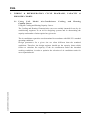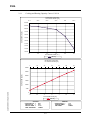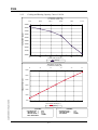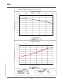
1
Technical Manual SPLIT SYSTEM AIR CONDITIONER 50 Hz A i r C o n d i t i o n e r s CAL CONTENTS page P-1 JULY 2000 5130-26135-86 A. PREFACE 1. CAL LINE GENERAL DESCRIPTION 1.1 Product Options 1.3 Technical data table Specifications for CAL (CASSETTE) 50Hz Models 1.4 Standards Compliance and Agency License Listings 1.5 Bar-code system 1-1 1-1 1-2 1-2 1-3 1-6 2. WIRING & REFRIGERATION CYCLE DIAGRAMS, CAPACITY & PRESSURE CHARTS2-1 2.1 Using CAL Model Air-Conditioner Cooling and Heating Capacity Curves 2.1.1 Cooling and Heating Capacity Curves CAL 18 2.1.2 Cooling and Heating Capacity Curves CAL 24 2.1.3 Cooling and Heating Capacity Curves CAL 36 2.1.4 Cooling and Heating Capacity Curves CAL 363 2.1.5 Cooling and Heating Capacity Curves CAL 483 2.1.6 System Performance Charts CAL 18 2.1.7 System Performance Charts CAL 24 2.1.8 System Performance Charts CAL 36 2.1.9 System Performance Charts CAL 363 2.1.10 System Performance Charts CAL 483 2-2 2-2 2-3 2-4 2-5 2-6 2-7 2-8 2-9 2-10 2-11 2.2 REFRIGERATION CYCLE 2.2.1 Refrigeration Cycle CAL 18 2.2.2 Refrigeration Cycle CAL 24 2.2.2.1Refrigeration Cycle CAL 24 (Effective from S/N1149052338) 2.2.3 Refrigeration Cycle CAL 36 2.2.3.1Refrigeration Cycle CAL 36 (Effective from S/N1149044026) 2.2.5 Refrigeration Cycle CAL 363 2.2.6 Refrigeration Cycle CAL 483 2-12 2-12 2-13 2-14 2-15 2-16 2-17 2-18 2.3 CASSETE - Low Profile In-Ceiling Unit 2-19 Bill of Material 2-26 PCB Placement 2-27 Electrical & wiring Diagram 2.4.1 CAL 18 / CAL 24 / CAL 36 1PH 2.4.2 CAL 363 / CAL 483 3 PH 2-28 2-28 2-29 2.4 1--1 I CAL A . Preface INTRODUCTION The Service Manual for CAL model split air-conditioners provides comprehensive technical documentation for the equipment. This manual contains information intended for a variety of uses and is intended for application engineers, architects, designers and various level service and installation personnel. This manual includes information on the optional features offered by the CAL series. In addition, it includes general information for service personnel on split air-conditioners, electrical wiring diagrams, refrigeration cycle diagrams and cooling & heating capacity JULY 2000 5130-26135-86 curves for the various series models. Created by: Alex LIBERMAN Technical Support International Marketing [email protected] Tadiran reserves the right to change product specifications without prior notice. 1-0P-1 CAL 1. CAL LINE GENERAL DESCRIPTION 1.1 Product Options Line: CAL Characteristics: Mini-Central 50Hz Models: Options 50Hz Models 1 PHASE 3 PHASE C H CAL 18 ✔ ✔ CAL 24 ✔ ✔ CAL 36 ✔ ✔ CAL 363 ✔ ✔ CAL 483 ✔ ✔ - Heating and Cooling by heat pump. C - Cooling only (No heat pump). JULY 2000 5130-26135-86 H 1-11-1 - Non Exist ✔ - Exist CAL 1.2 Nameplate Information Technical information for a specific unit appears on the unit nameplate, which is attached to the indoor and/or the outdoor units. (See Figure 1-1: Typical Technical Data Nameplate for 50Hz models). The 50Hz models Nameplate includes the following information: MODEL Air-conditioner (A/C) model name. CLIMATE CLASS Type of climate for which the unit was designated - classified by: Class A (standard) or Class B (desert conditions < 52°C.) VOLT/PHASE/Hz A/C power supply, for example: 230/1/50 = 230V/1ph/50Hz. COS (ϕ) Power factor for the unit. FUSE Required fuse size (Amp.) CAPACITORS [ µ F] All capacitor values according to this sequence (Compressor capacitor / Outdoor motor capacitor / Indoor motor capacitor). REFRIGERANT R-22 [gr] Quantity of refrigerant charge (for 8 m piping length). COMPRESSOR Type and Catalogue No. of compressor. CAPACITY BTU/H Cooling and Heating capacity in Btu/h according to ISO 5151 standard (1000Btu/h=293W). CAPACITY W Cooling and Heating capacity in Watts (1000W=3,413Btu/h). INPUT POWER Power consumption in cooling and heating modes (Watts). AMPER Current consumption in cooling and heating modes (Amp.). SERIAL NO. Unit serial number (normally blank, since Bar Code system is JULY 2000 5130-26135-86 used). 1-21-2 CAL 1 . 3 Technical data table Specifications for CAL (CASSETTE) 50Hz Models Model 50Hz Cooling Capacity Btu/h Kcal/h (Watt) Btu/h Kcal/h (Watt) Watt Watt Amp. - 1ph - 3ph Cool Heat Heating Capacity Power Consumption Cooling Power Consumption Heating Operating Current (Cooling/Heating) EER – Energy Efficiency Ratio COP– Coefficient Of CAL-18H CAL-24H CAL-36H CAL-48H 20,000 5,050 (5,860) 21,000 5,300 (6,150) 2,050 2,120 9.4 / 9.7 26,000 6,560 (7,620) 27,000 6,820 (7,910) 2,610 2,640 12.0 / 12.1 34,000 8,580 (9,960) 34,000 8,580 (9,960) 3,780 3,110 17.4 / 14.3 45,000 11,360 (13,190) 45,500 11,490 (13,330) 4,790 4,440 7.9,6.2,6.2/7.5,5.8,5.8 8.8,7.2,7.2/8.7,7.0,7.0 9.8 2.9 10.0 3.0 9.0 3.2 9.0 3.0 Performance Moisture Removal Power Supply (Volt/Hz/ph) l/h 1Ph 3Ph j f - Inch m (ft) m (ft) Amp. 0.92 1/4" - 1/2" Indoor Unit 50Hz CAL-I18H Front Panel Air Filter Unit Dimensions (HxLxD) Color Power Factor Refrigerant Lines Maximum Piping Length Maximum Height Difference Time Delay Fuse - 1ph - 3ph Control Mode Temperature Control A/C Options: Grill Dimensions (HxLxD) OCT. 2000 5130-26135-86 Air Flow (Turbo/High/Low) Noise Level Unit Net Weight Grill Net Weight Indoor Fan Motor: Speed (Turbo/High/Low) Full Load Amperage Motor Capacitor Electric Heater (original model) Blower Wheel mm in mm in m3/h cfm dBA Kg. (Lb.) Kg. (Lb.) Watt R.P.M. Amp. mF/Volt Watt Type Outdoor Unit 50Hz Casing Dimensions (HxLxD) Color mm in 2.2 2.4 3.2 220/240V, 50Hz, 1ph 380/415V, 50Hz, 3ph 0.95 0.95 (0.92 - 3Ph) 1/4" - 5/8" 3/8" - 3/4" 30 (98') 15 (49') 16 25 3 ¥ 10 I.R. Remote Control / Auto. Microcomputer C / H / HDE (drain pan available for all models) 220/240V 50Hz 1ph - 16 - CAL-I24H 5.2 380/415V, 50Hz, 3ph 0.92 3/8" - 3/4" CAL-I36H 3 ¥ 16 CAL-I48H White 1 Removable/Washable Filter 575 ¥ 575 ¥ 295 22 5/8 ¥ 22 5/8 ¥ 11 5/8 720 ¥ 720 ¥ 30 28 11/32 ¥ 28 11/32 ¥ 1 3/16 790 / 700 / 620 970 / 725 / 650 465 / 410 / 365 570 / 425 / 380 43 / 39 / 35 49 / 42 / 39 27 (59) 28 (62) 3 (6.5) 3 (6.5) 885 / 790 / 700 2 Removable/Washable Filters 1,175 ¥ 575 ¥ 295 46 1/4 ¥ 22 5/8 ¥ 11 5/8 1,320 ¥ 720 ¥ 30 51 31/32 ¥ 28 11/32 ¥ 1 3/16 1,630 / 1,325 / 1,180 1,830 / 1,480 / 1,070 960 / 780 / 695 1,075 / 870 / 630 46 / 40 / 34 53 / 46 / 39 50 (110) 53 (117) 6 (13) 6 (13) 1130 / 875 / 790 980 / 800 / 710 1190 / 970 / 705 2 ¥ 0.6 0.6 2mF / 370V 1,600 2.5mF / 370V 1,600 CAL-O18H CAL-O24H 2mF / 370V 2 ¥ 1,200 2.5mF / 370V 2 ¥ 1,200 CAL-O36H CAL-O48H White 900 ¥ 640 ¥ 320 35 7/16 ¥ 21 1/4 ¥ 12 19/32 1100 ¥ 640 ¥ 320 43 5/16 ¥ 21 1/4 ¥ 12 19/32 Air Flow m3/h 4,080 / 3,485 / 2,550 (Turbo/High/Low) cfm 2,400 / 2,050 / 1,500 Noise Level dBA 53 / 50 / 46 53 / 50 / 46 Net Weight Kg (Lb.) 66 (145) 75 (165) Fittings Type Flare Compressor 1ph CR24K6PFZ-502 H29B32UABKA H28A423ABKA 3ph H23A423DBEA Thermal Protector Internal Overload Full Load Amperage - 1ph Amp. 10.4 12.4 16.8 - 3ph 3 ¥ 5.7 Lock Rotor Amperage - 1ph Amp. 51.0 76.0 92.0 - 3ph 3 ¥ 39.0 Compressor Capacitor mF/Volt 45mF / 400V 40mF / 400V 60mF / 400V Capillary 1ph 2 ¥ 0.059" ¥ 30" 2 ¥ 0.064" ¥ 32" 2 ¥ 0.070" ¥ 32" 3ph 2 ¥ 0.070" ¥ 32" R-22 Freon Gas- 1ph gr. (Oz.) 2,050 (72.3) 2,120 (74.8) 2,500 (88.2) - 3ph 2,500 (88.2) Oil for Compressor Type 3GS or Compatible Outdoor Fan Motor: HP 1/5 Motor Capacitor mF/Volt 5mF / 400V Speed R.P.M. 900 / 700 / 500 Motor Full Load Amperage Amp. 1.3 Specifications and performance data are subject to change without notice. For CAL-24, CAL-36 and CAL-363, use the tubing adapter that supplied inside the condenser. 1-31-3 1140 ¥ 640 ¥ 400 44 7/8 ¥ 25 3/16 ¥ 15 3/4 54 / 51 / 47 90 (198) H23A56QDBEA 3 ¥ 7.5 3 ¥ 62.0 Expansion Valve 3,600 (127.0) CAL 1 . 4 Standards Compliance and Agency License Listings ✔ - Approved - - Not Applicable (N/A) 50 Hz Model CE GS(TUV) EUROVENT CAL 18 ✔ ✔ ✔ CAL 24 ✔ ✔ ✔ CAL 36 ✔ ✔ ✔ CAL 363 ✔ ✔ ✔ CAL 483 ✔ ✔ ✔ - Confirmation according to CE directives. Geprüfte Sicherheit (safety approved - German law) International Standards Organization European Committee of air handling, air conditioning and refrigerating equipment manufacturers. T he s Insti tuti on da rd of SI el Is ra St an ISO 9001 ua l it .. TUV Rheinland .. geprufte Sicherheit rm Q JULY 2000 5130-26135-86 CE GS ISO EUROVENT y As su re d Fi 1-41-4 CAL 1.5 Bar-code system Finished goods (packed evaporator or condenser) are labeled by Bar Code for easy identification of product configuration and storage. Each unit has Bar Code labels as shown below, one on each side of the packed unit and small labels (with unit serial number only) are located on each unit (near the nameplate on the evaporator, beneath the valves and in the connection box of the condenser). The structure of the Bar Code label: A. Complete unit name, for example: GFL-2020C (GFL-2020 model without heat pump). B. Important components (up to 2 lines) about the specific unit, for example: CARRIER MEXICO, NEW R.C, TAC-404. C. Unit catalog number/order number, for example: CATALOG NO. 51382057712/880472 (prefix of 5138 for evaporator and 5139 for condenser). D. Unit serial number, for example: S/N 2248119059 = 22 - for factory use; 48 - 1998; 059185 - running (serial) number. E. Tadiran order number, for example: 880472 = 88 - 1998; 0 group; 472 order running number. F. Small S/N cables (X3). An additional Bar Code label displays the PALLET NO. (see next page) and is used for storage only. A B JULY 2000 5130-26135-86 C D E F Figure 1-4: Typical Evaporator/Condenser Unit Bar Code Identification Label 1-51-5 CAL JULY 2000 5130-26135-86 Figure 1-5: Typical Pallet Bar Code Label 1-61-6 CAL 2. WIRING & REFRIGERATION CYCLE DIAGRAMS, CAPACITY & PRESSURE CHARTS 2.1 Using CAL Model Air-Conditioner Cooling and Heating Capacity Curves Using the Cooling and Heating Capacity Curves. The Cooling and Heating Characteristics curves are mainly intented for use by air conditioning engineers as an aid in designing systems and in determining the capacity and number of units required at a given site. JULY 2000 5130-26135-86 The air conditioner capacities were determined in accordance with ISO 5151 standard operating conditions: Design parameters for a given site are often different than the standard conditions. Therefore, the design engineer should use the capacity charts which follow to calculate the capacity of the air conditioners under the intended working conditions, in order to optimize the selection of air conditioner units for use at a particular site. 1-72-1 CAL 2.1.1 Cooling and Heating Capacity Curves CAL 18 COOLING CAPACITY OUTDOOR TEMP. [°F] 75.2 82.4 24 28 89.6 96.8 104 111.2 40 44 21000 20500 CAPACITY [Btu/H] 20000 19500 19000 18500 18000 17500 17000 16500 16000 32 36 OUTDOOR TEMP. [°C] [Btu/H] HEATING CAPACITY OUTDOOR TEMP [°F] 5 14 -15 -10 23 32 41 50 59 5 10 15 30000 CAPACITY [Btu/H] 25000 20000 15000 10000 JULY 2000 5130-26135-86 5000 0 -5 0 OUTDOOR TEMP [°C] [Btu/H] COOLING * OUTDOOR R.H. = 40% INDOOR R.H. = 47% INDOOR TEMP. = 27 °C TURBO MAX. AIR SPEED: 1-82-2 HEATING * OUTDOOR R.H. = 77% INDOOR TEMP. = 20 °C AIR SPEED: TURBO CAL 2.1.2 Cooling and Heating Capacity Curves CAL 24 COOLING CAPACITY OUTDOOR TEMP. [°F] 75.2 29000 82.4 89.6 96.8 104 111.2 32 36 40 44 50 59 28000 CAPACITY [Btu/H] 27000 26000 25000 24000 23000 22000 21000 20000 24 28 OUTDOOR TEMP. [°C] [Btu/H] HEATING CAPACITY OUTDOOR TEMP [°F] 14 23 32 41 35000 CAPACITY [Btu/H] 30000 25000 20000 15000 JULY 2000 5130-26135-86 10000 5000 -15 -10 -5 0 5 10 OUTDOOR TEMP [°C] [Btu/H] COOLING * OUTDOOR R.H. = 40% INDOOR R.H. = 47% INDOOR TEMP. = 27 °C TURBO MAX. AIR SPEED: 1-92-3 HEATING * OUTDOOR R.H. = 77% INDOOR TEMP. = 20 °C AIR SPEED: TURBO 15 CAL 2.1.3 Cooling and Heating Capacity Curves CAL 36 COOLING CAPACITY OUTDOOR TEMP. [°F] 75.2 45000 82.4 89.6 96.8 104 111.2 28 32 36 40 44 50 59 40000 CAPACITY [Btu/H] 35000 30000 25000 20000 15000 10000 5000 0 24 OUTDOOR TEMP. [°C] [Btu/H] HEATING CAPACITY OUTDOOR TEMP [°F] 14 23 32 41 45000 40000 CAPACITY [Btu/H] 35000 30000 25000 20000 15000 10000 JULY 2000 5130-26135-86 5000 0 -15 -10 -5 0 5 10 OUTDOOR TEMP [°C] [Btu/H] COOLING * OUTDOOR R.H. = 40% INDOOR R.H. = 47% INDOOR TEMP. = 27 °C TURBO MAX. AIR SPEED: 1-102-4 HEATING * OUTDOOR R.H. = 77% INDOOR TEMP. = 20 °C AIR SPEED: TURBO 15 CAL 2.1.4 Cooling and Heating Capacity Curves CAL 363 COOLING CAPACITY OUTDOOR TEMP. [°F] 75.2 45000 82.4 89.6 96.8 104 111.2 28 32 36 40 44 50 59 40000 CAPACITY [Btu/H] 35000 30000 25000 20000 15000 10000 5000 0 24 OUTDOOR TEMP. [°C] [Btu/H] HEATING CAPACITY OUTDOOR TEMP [°F] 14 23 32 41 45000 40000 CAPACITY [Btu/H] 35000 30000 25000 20000 15000 10000 JULY 2000 5130-26135-86 5000 0 -15 -10 -5 0 5 10 OUTDOOR TEMP [°C] [Btu/H] COOLING * OUTDOOR R.H. = 40% INDOOR R.H. = 47% INDOOR TEMP. = 27 °C TURBO MAX. AIR SPEED: HEATING * OUTDOOR R.H. = 77% INDOOR TEMP. = 20 °C AIR SPEED: TURBO 1-112-5 15 CAL 2.1.5 Cooling and Heating Capacity Curves CAL 483 COOLING CAPACITY OUTDOOR TEMP. [°F] 75.2 82.4 24 28 89.6 96.8 104 111.2 32 36 OUTDOOR TEMP. [°C] [Btu/H] 40 44 50 59 47000 CAPACITY [Btu/H] 46000 45000 44000 43000 42000 41000 40000 HEATING CAPACITY OUTDOOR TEMP [°F] 14 23 32 41 60000 CAPACITY [Btu/H] 50000 40000 30000 20000 JULY 2000 5130-26135-86 10000 0 -15 -10 -5 0 5 10 OUTDOOR TEMP [°C] [Btu/H] COOLING * OUTDOOR R.H. = 40% INDOOR R.H. = 47% INDOOR TEMP. = 27 °C TURBO MAX. AIR SPEED: 1-122-6 HEATING * OUTDOOR R.H. = 77% INDOOR TEMP. = 20 °C AIR SPEED: TURBO 15 CAL 2.1.6 System Performance Charts CAL 18 COOLING DISCHARGE PRESSURE 350 HEATING DISCHARGE PRESSURE 400 PRESSURE [psi] PRESSURE [psi] 300 250 200 150 100 350 300 250 200 150 100 50 50 0 0 -10 24 28 32 36 40 OUTDOOR TEMP. [°C] 84 PRESSURE [psi] PRESSURE [psi] 82 80 78 76 74 72 70 -10 32 36 40 OUTDOOR TEMP. [°C] 0 5 10 15 HEATING INDOOR AIR dT 30 25 dT [°C] 16 dT [°C] -5 35 17 15 14 20 15 10 5 13 JULY 2000 5130-26135-86 15 OUTDOOR TEMP. [°C] 44 COOLING INDOOR AIR dT* 18 10 90 80 70 60 50 40 30 20 10 0 68 28 5 HEATING SUCTION PRESSURE 86 24 0 OUTDOOR TEMP. [°C] COOLING SUCTION PRESSURE 88 -5 44 0 -10 12 24 28 32 36 40 OUTDOOR TEMP. [°C] * OUTDOOR R.H. = INDOOR R.H. = INDOOR TEMP. = MAX. AIR SPEED: 40% 51% 80 °F TURBO 1-132-7 44 -5 0 5 10 OUTDOOR TEMP. [°C] * OUTDOOR R.H. = INDOOR TEMP. = AIR SPEED: 70% 70 °F TURBO 15 CAL 2.1.7 System Performance Charts CAL 24 HEATING DISCHARGE PRESSURE 400 350 350 300 PRESSURE [psi] PRESSURE [psi] COOLING DISCHARGE PRESSURE 300 250 200 150 100 250 200 150 100 50 50 0 0 -10 24 28 32 36 40 44 -5 0 5 10 15 OUTDOOR TEMP. [°C] OUTDOOR TEMP. [°C] HEATING SUCTION PRESSURE COOLING SUCTION PRESSURE 90 90 80 70 PRESSURE [psi] PRESSURE [psi] 85 80 75 70 60 50 40 30 20 10 0 65 24 28 32 36 40 -10 44 -5 0 5 10 15 OUTDOOR TEMP. [°C] OUTDOOR TEMP. [°C] HEATING INDOOR AIR dT COOLING INDOOR AIR dT* 35 25 30 20 dT [°C] dT [°C] 25 15 10 20 15 10 JULY 2000 5130-26135-86 5 5 0 0 24 28 32 36 40 OUTDOOR TEMP. [°C] * OUTDOOR R.H. = INDOOR R.H. = INDOOR TEMP. = MAX. AIR SPEED: 40% 51% 80 °F TURBO 1-142-8 44 -10 -5 0 5 10 OUTDOOR TEMP. [°C] * OUTDOOR R.H. = INDOOR TEMP. = AIR SPEED: 70% 70 °F TURBO 15 CAL 2.1.8 System Performance Charts CAL 36 COOLING DISCHARGE PRESSURE HEATING DISCHARGE PRESSURE 300 350 PRESSURE [psi] PRESSURE [psi] 400 300 250 200 150 100 250 200 150 100 50 50 0 0 -10 24 28 32 36 40 0 5 10 15 OUTDOOR TEMP. [°C] OUTDOOR TEMP. [°C] COOLING SUCTION PRESSURE HEATING SUCTION PRESSURE 90 88 86 84 82 80 78 76 74 72 80 70 60 PRESSURE [psi] PRESSURE [psi] -5 44 24 28 32 36 40 50 40 30 20 10 0 -10 44 -5 0 5 10 15 OUTDOOR TEMP. [°C] OUTDOOR TEMP. [°C] COOLING INDOOR AIR dT* HEATING INDOOR AIR dT 25 JULY 2000 5130-26135-86 20 15 14.5 14 13.5 13 12.5 12 dT [°C] dT [°C] 16 15.5 15 10 5 0 24 28 32 36 40 OUTDOOR TEMP. [°C] * OUTDOOR R.H. = INDOOR R.H. = INDOOR TEMP. = MAX. AIR SPEED: 40% 51% 80 °F TURBO 1-152-9 44 -10 -5 0 5 10 OUTDOOR TEMP. [°C] * OUTDOOR R.H. = INDOOR TEMP. = AIR SPEED: 70% 70 °F TURBO 15 CAL 2.1.9 System Performance Charts CAL 363 COOLING DISCHARGE PRESSURE HEATING DISCHARGE PRESSURE 300 350 PRESSURE [psi] PRESSURE [psi] 400 300 250 200 150 100 250 200 150 100 50 50 0 0 -10 24 28 32 36 40 0 5 10 15 OUTDOOR TEMP. [°C] OUTDOOR TEMP. [°C] COOLING SUCTION PRESSURE HEATING SUCTION PRESSURE 90 88 86 84 82 80 78 76 74 72 80 70 60 PRESSURE [psi] PRESSURE [psi] -5 44 24 28 32 36 40 50 40 30 20 10 0 -10 44 -5 0 5 10 15 OUTDOOR TEMP. [°C] OUTDOOR TEMP. [°C] COOLING INDOOR AIR dT* HEATING INDOOR AIR dT 25 JULY 2000 5130-26135-86 20 15 14.5 14 13.5 13 12.5 12 dT [°C] dT [°C] 16 15.5 15 10 5 0 24 28 32 36 40 OUTDOOR TEMP. [°C] * OUTDOOR R.H. = INDOOR R.H. = INDOOR TEMP. = MAX. AIR SPEED: 40% 51% 80 °F TURBO 1-16 2-10 44 -10 -5 0 5 10 OUTDOOR TEMP. [°C] * OUTDOOR R.H. = INDOOR TEMP. = AIR SPEED: 70% 70 °F TURBO 15 CAL 2.1.10 System Performance Charts CAL 483 COOLING DISCHARGE PRESSURE HEATING DISCHARGE PRESSURE 400 350 PRESSURE [psi] PRESSURE [psi] 350 300 250 200 150 300 250 200 150 100 100 50 50 0 0 24 28 32 36 40 OUTDOOR TEMP. [°C] -10 44 80 82 70 80 60 78 50 76 74 72 70 68 40 30 20 10 0 66 24 28 32 36 40 OUTDOOR TEMP. [°C] -10 44 COOLING INDOOR AIR dT* 0 5 10 15 HEATING INDOOR AIR dT 35 30 19.5 19 25 dT [°C] dT [°C] -5 OUTDOOR TEMP. [°C] 20.5 20 JULY 2000 5130-26135-86 15 HEATING SUCTION PRESSURE 84 PRESSURE [psi] PRESSURE [psi] COOLING SUCTION PRESSURE -5 0 5 10 OUTDOOR TEMP. [°C] 18.5 18 17.5 17 16.5 20 15 10 5 16 0 24 28 32 36 40 OUTDOOR TEMP. [°C] * OUTDOOR R.H. = INDOOR R.H. = INDOOR TEMP. = MAX. AIR SPEED: 40% 51% 80 °F TURBO 1-17 2-11 44 -10 -5 0 5 10 OUTDOOR TEMP. [°C] * OUTDOOR R.H. = INDOOR TEMP. = AIR SPEED: 70% 70 °F TURBO 15 CAL 2.2 REFRIGERATION CYCLE 2.2.1 Refrigeration Cycle CAL 18 1/2" D V' V C S MUFFLER RV E COPELAND COMP. CR24K V V 20,100 BTU/h 5,075 Kcal/h 1,860 WATTS 10.8 EER V' MOTOR 78 Watt 700/790/ 885 RPM V AIR AIR IN OUT AIR AIR IN OUT WASHABLE AIR FILTER MOTOR 1/5 HP 900/700/500 RPM AIR AIR IN OUT PROPELLER PLASTIC 6 BLADES 500 mm D. BLOWERS QTY: 1 DIAM. : 282 mm L' WIDTH : 148 mm BLADES : 13 CAPILLARY L L 1/4" JULY 2000 5130-26135-86 2 X 0.059" X 30" OUTDOOR COIL INDOOR COIL 2 ROWS 4 CIRCUITS 13 F.P.I. 48 PLAIN TUBES 2 ROWS 2 CIRCUITS 14 F.P.I. 18 GROOVED TUBES 1-18 2-12 CAL 2.2.2 Refrigeration Cycle CAL 24 5/8" D V' V C S MUFFLER RV E BRISTOL COMP. H25B303 V' V V 26,500 BTU/h 6,690 Kcal/h 2,430 WATTS 10.9 EER MOTOR 101 Watt 790/875/ 1130 RPM V AIR AIR IN OUT AIR AIR IN OUT WASHABLE AIR FILTER MOTOR 1/5 HP 900/700/500 RPM AIR AIR IN OUT PROPELLER PLASTIC 6 BLADES 500 mm D. BLOWERS 1 QTY: DIAM. : 282 mm L' WIDTH : 148 mm BLADES : 13 CAPILLARY L L 3/8" 1/4" JULY 2000 5130-26135-86 2 X 0.064" X 32" OUTDOOR COIL INDOOR COIL 2 ROWS 4 CIRCUITS 12 F.P.I. 48 PLAIN TUBES 3 ROWS 3 CIRCUITS 14 F.P.I. 27 GROOVED TUBES 1-19 2-13 CAL 2.2.2.1 Refrigeration Cycle CAL 24 (Effective from S/N1149052338) 5/8" D V' V C S MUFFLER RV E BRISTOL COMP. H29B32U V' V V 27,500 BTU/h 6,940 Kcal/h 2,570 WATTS 10.7 EER MOTOR 101 Watt 790/875/ 1130 RPM V AIR AIR IN OUT AIR AIR IN OUT WASHABLE AIR FILTER MOTOR 1/5 HP 900/700/500 RPM AIR AIR IN OUT PROPELLER PLASTIC 6 BLADES 500 mm D. BLOWERS 1 QTY: DIAM. : 282 mm L' WIDTH : 148 mm BLADES : 13 CAPILLARY L L 3/8" 1/4" JULY 2000 5130-26135-86 2 X 0.064" X 32" OUTDOOR COIL INDOOR COIL 2 ROWS 4 CIRCUITS 13 F.P.I. 48 PLAIN TUBES 3 ROWS 3 CIRCUITS 14 F.P.I. 27 GROOVED TUBES 1-20 2-14 CAL 2.2.3 Refrigeration Cycle CAL 36 5/8" 3/4" D V' V C S MUFFLER RV E COPELAND COMP. CR42K6 V' V V 35,200 BTU/h 8,890 Kcal/h 3,240 WATTS 10.9 EER V AIR MOTOR 87 Watt 710/800/ 980 RPM IN AIR AIR IN OUT 2 WASHABLE AIR FILTERS MOTOR 1/5 HP 900/700/500 RPM AIR OUT AIR IN PROPELLER PLASTIC 6 BLADES 500 mm D. L' BLOWERS QTY: 2 DIAM. : 282 mm WIDTH : 148 mm BLADES : 13 CAPILLARY JULY AUG.2000 19995130-26135-86 L L 3/8" 2 X 0.070" X 32" OUTDOOR COIL INDOOR COIL 2 ROWS 4 CIRCUITS 16 F.P.I. 48 PLAIN TUBES 2 ROWS 4 CIRCUITS 2X18 GROOVED TUBES 1-21 2-15 CAL 2.2.3.1 Refrigeration Cycle CAL 36 (Effective from S/N1149044026) 5/8" 3/4" D V' V C S MUFFLER RV E V BRISTOL COMP. H28A423 V' V 37,000 BTU/h 9,340 Kcal/h 3,410 WATTS 10.9 EER V AIR MOTOR 87 Watt 710/800/ 980 RPM IN AIR AIR IN OUT 2 WASHABLE AIR FILTERS MOTOR 1/5 HP 900/700/500 RPM AIR OUT AIR IN PROPELLER PLASTIC 6 BLADES 500 mm D. L' BLOWERS QTY: 2 DIAM. : 282 mm WIDTH : 148 mm BLADES : 13 CAPILLARY JULY 2000 5130-26135-86 L L 3/8" 2 X 0.070" X 32" OUTDOOR COIL INDOOR COIL 2 ROWS 4 CIRCUITS 16 F.P.I. 48 PLAIN TUBES 2 ROWS 4 CIRCUITS 14 F.P.I. 2X18 GROOVED TUBES 1-22 2-16 CAL 2.2.4 Refrigeration Cycle CAL 363 5/8" 3/4" D V' V C S MUFFLER RV E BRISTOL COMP. H23A423 V' V V 35,200 BTU/h 8,890 Kcal/h 3,400 WATTS 10.4 EER V AIR MOTOR 87 Watt 710/800/ 980 RPM IN AIR AIR IN OUT 2 WASHABLE AIR FILTERS MOTOR 1/5 HP 900/700/500 RPM AIR OUT AIR IN PROPELLER PLASTIC 6 BLADES 500 mm D. L' BLOWERS QTY: 2 DIAM. : 282 mm WIDTH : 148 mm BLADES : 13 CAPILLARY JULY 2000 5130-26135-86 L L 3/8" 2 X 0.070" X 28" OUTDOOR COIL INDOOR COIL 3 ROWS 4 CIRCUITS 13 F.P.I. 72 PLAIN TUBES 2 ROWS 4 CIRCUITS 14 F.P.I. 2X18 GROOVED TUBES 1-23 2-17 CAL 2.2.5 Refrigeration Cycle CAL 483 3/4" D V' V C S MUFFLER RV E CAPILLARY BY PASS BRISTOL COMP. H23A56 V' V V 47,500 BTU/h 1,200 Kcal/h 4,560 WATTS 10.4 EER V AIR MOTOR 87 Watt 710/800/ 980 RPM IN AIR IN OUT 2 WASHABLE AIR FILTERS EXTERNAL EQUALIZER AIR MOTOR 1/5 HP 900/700/500 RPM PROPELLER PLASTIC 6 BLADES 500 mm D. AIR OUT AIR IN L' JULY 2000 5130-26135-86 L BLOWERS 2 QTY: DIAM. : 282 mm WIDTH : 148 mm BLADES : 13 L 3/8" OUTDOOR COIL THERMAL EXPANSION VALVE INDOOR COIL 3 ROWS 6 CIRCUITS 16 F.P.I. 72 PLAIN TUBES 2 ROWS 4 CIRCUITS 14 F.P.I. 2X18 GROOVED TUBES 1-24 2-18 CAL 2.3 Cassette – Low Profile In-Ceiling Unit The Cassette unit designed to be installed between the drop (false ceiling) and the main ceiling. The Cassette unit allows delivering high capacities without using metal or flexible ducts. Cassette Advantages: One. Improved air distribution (better than high wall or floor unit). Two. Does not occupy wall or floor area. Three. Option for fresh air (built in). Four. Option for conditioned air supply to adjacent room (built in). Five. The indoor unit designed to the size of (one or two) standard false ceiling panels. Installation: 1. The Cassette evaporator must be installed in a level position. 2. Electrical connections are similar to the ANL-S connections, excluding the TH-1 & TH-2 sensors that are connected inside the evaporator on the blower orifice and the coil. Connect the TH-1 & TH-2 sensors to the electrical box. 3. Piping connections: the valves are fixed to the indoor unit allowing manipulation of the valves using a single wrench. 4. Evaporator adjustment: four, three or two air outlets available, according to the installation needs. Tubing Adapters: AUG. 2000 5130-26135-86 CAL-24: CAL-24: The indoor indoorfittings fittingsare are1/4" 1/4"(discharge) (discharge)and and 5/8” 5/8¢(suction), (suction),while whilethe theoutdoor outdoorfittings fittingsare are3/8" 3/8" The (discharge) and 5/8 ¢ (suction). With each outdoor unit, we supply inside the outdoor additional (discharge) 5/8” Inside each CAL-24 outdoor unit, an additional fitting adapter Fitting adapter 1/4" to 3/8 ¢ (Cat. No. 51305815790 – supplied condenser, no need to 1/4" to 3/8” is supplied (Cat. No. 51305815790 – supplied with with eacheach condenser, no need to order). order). Thisadapter Fitting must Adapter must be installed on the condenser 1/4" discharge Fitting. The This fitting be installed on the evaporator 1/4" discharge fitting. The interconnecting refrigerant tubesrefrigerant should be tubes only 3/8” (discharge) and 5/8” (suction). interconnecting are to be only 1/4 ¢ (discharge) and 5/8¢ (suction). CAL-36: CAL-36: The The indoor indoorfittings fittingsare are3/8" 3/8"(discharge) (discharge)and and 3/4” 3/4¢(suction), (suction),while whilethe theoutdoor outdoorfittings fittingsare are3/8" 3/8" (discharge) 5/8”¢ (suction). eachoutdoor CAL-36unit, outdoor unit, additional adapter (discharge) and 5/8 (suction). Inside With each we supply inside thefitting outdoor additional 3/4" to 5/8”is supplied (Cat. No. 51305815780 – supplied with with eacheach condenser, no need to order). Fitting adapter 3/4" to 5/8 ¢ (Cat. No. 51305815780 – supplied condenser, no need to This fitting adapter must be installed on the evaporator 3/4" suction fitting. The interconnecting order). This Fitting Adapter must be installed on the condenser 3/4" suction Fitting. The refrigerant tubesrefrigerant should be tubes only 3/8” (discharge) and 5/8” (suction). interconnecting are to be only 3/8 ¢ (discharge) and 3/4¢ (suction). 1-25 2-19 CAL Replacing the TH-1 (return/intake air) sensor During TH-1 replacement, removal of the intake grill is required (turn the plastic screws 90°). Then, totally remove the front cover by unscrewing the screws on the intake grill corners and also remove the drain pan. Replacing the TH-2 (indoor coil temperature) sensor Begin with the procedures as in the replacement of TH-1 sensor. Remove the drain pan by unscrewing the (4 or 6) screws that connect the drain pan to the evaporator body. Replacing Indoor Fan Motor Capacitor Begin with the procedures as in the replacement of TH-1 sensor. Remove the orifice (intake assembly) from the drain pan by unscrewing 2 screws. Remove the blower wheel by unscrewing its central (holding) screw. Now the capacitor can easily be replaced. Replacing Indoor Fan Motor Begin with the procedures as in the replacement of indoor fan motor capacitor. Disconnect the motor electrical harness. Replace the fan motor. Replacing Drain Pump Begin with the procedures as in the replacement of TH-2 sensor. Remove the blower wheel. Unscrew 2 screws that attaches the drain pump. Replacing Safety Level Switch Begin with the procedures as in the replacement of TH-2 sensor and unscrew the screws that attach the safety level switch. Finally, disconnect the safety level switch electrical harness. JULY 2000 5130-26135-86 Replacing Indoor Coil Begin with the procedures as in the replacement of the drain pump. Remove both coil supports (2 screws) and unscrew the single screw that attaches the coil to the evaporator back. In addition, the following components must be removed before removing the indoor coil: fittings (6 screws), drain pump, safety level switch and TH-2 sensor. Cassette Drain Pump Water Elevation Water elevation is 300 mm from false ceiling. The drain pipe cannot go higher than 300 mm because of the risk of water return from the pipe, when the unit stops (back flow) which could overflow the drain pan! 1-26 2-20 CAL Specification for the Water (Drain) Pump Control Water (Drain) Pump specifications Operation Life: Power Supply: Motor Type: Operating temperature: Operating humidity: Working fluid: Height difference: 15 years or 15,000 hours. 230V±10% - 1ph - 50Hz. Single phase 2 poles. 0 - 40∞C. Maximum 95%. Water condensation at 5∞C min. See the installation instructions of the unit. The Water Pump control is designed to control the water pump in the Cassette (CAL) type air conditioners. The Water Pump control operates the water pump with the TAC-404 Electronic Control Family. The Water Pump control is connected between the Main (TAC-444) and the Display Assy (TAC-460) in series. The main task of the water pump is to prevent a water flood whenever the air conditioner unit is in Cool mode or when switching to Off mode after Cool mode. The basic algorithm is that the water pump will work whenever the air conditioner is in cool mode and for the next 5 min. after the compressor is turned to Off in Cool Mode. Mechanical design: The water pump is designed to fit into the electric control box of the Cassette air conditioner. The PCB is attached to the electronic control box by four “snaps”. The “snaps” are placed on the four PCB corners (4mm hole). The Control is connected to the Main Board (TAC-444) and the Display Assy (TAC-460) via an RJ11 connector. The Control is connected to the Safety Level Switch (flood sensor) via two 6.3mm terminals. The Control is connected to the water pump via two 4.7mm terminals. JULY 2000 5130-26135-86 The control is connected to 230Vac power supply via a two terminal block. Electrical design: The pump control is powered by the TAC-444 main unit with a 10-18Vdc unregulated power supply. The pump control “reads” the communication line using the Current loop method. 1-27 2-21 CAL Inputs: Item 1. Description Operation Designation Main – Control Connects between the Main control unit communication (TAC-444) and the Pump Control. Control – Display Connects between the Pump control and Communication the Display (TAC-460). Safety Level Switch Signals the unit in case the drain has (flood sensor) overflowed. 4. Power 15V Unregulated DC 50mA. Via Con1. 5. Communication 20mA Current loop method. Via Con1. Description Pump Control Operation 220Vac 1A N/O Control Designation Con.4 2. 3. Con1. Con2. Con3. Output: Item 1. Performance: The Pump Control uses the 20mA current loop method or the Open Collector method to monitor the communication between the TAC-444 – Main Unit & the TAC-460 Display. Normal operation: The Pump Control drives the Water Pump in the following conditions: ∑ When the A/C is in Cool mode (Reverse Valve off) and the compressor is activated. ∑ The Water Pump works continuously, as long as the compressor works, in cooling mode. ∑ The Water Pump will work for additional 5min. after any compressor stops (in Cool mode). ∑ Immediately when the safety level switch (flood sensor) indicates overflow. JULY 2000 5130-26135-86 When the floating sensor indicates overflow and turns the compressor off (temporary or total system halt) the Water Pump will work for additional 5min. ∑ After entering the Rest Loop (thermostat stop), the Water Pump will work for additional 5min. ∑ After a system operation halt (failure), the Water Pump will work for additional 5min. ∑ When switching from Cool to Heat mode, the Water Pump will work for additional 5min. ∑ In Heat mode, the water pump is always switched off. 1-28 2-22 CAL Recovery from power failures: The Pump-Control will activate the water pump for 5 min. each time after power recovery if the previous mode was Cool mode. Emergency operation: When the Pump Control detects a water overflow, by the safety level switch, it stops the communication between the TAC-444 - Main unit and the TAC-460 – Display. As mentioned above, the Pump-Control is connected in series between the TAC-444 and the TAC-460. The Pump-Control stops all commination simply by disconnecting the Display from the Main. This will cause the POWER indication light to flash (as in “normal” communication failure). During that time the Pump Control will activate the Water Pump as long as needed. The Pump Control will reactivate the communication when the overflow sensor is switched off. In case the overflow situation is repeated 3 times during a period of 30min., the Pump-Control will disable the operation of the A/C (total system halt), by disconnecting the communication, until a power reset. Otherwise, the Pump Control will begin the counting again. Recovery from the total system halt is done by sending Off to the system and then re-entry to On by mean of the 3-position slide switch (on the Display Assy). In case the safety level switch continuously signals fault (for a long time period), the Pump Control JULY 2000 5130-26135-86 will disconnect the communication, until the water level drops to normal. 1-29 2-23 CAL Water (Drain) Pump Troubleshooting Chart Warning: Always unplug the A/C before performing cleaning or maintenance activities. Symptom 1 Constant overflow. Probable Cause Corrective Action 1. Faulty Safety Level Switch. 1. Replace Safety Level Switch. 2. Stuck Safety Level Switch. 2. Remove obstruction or replace Safety Level Switch. 3. Safety Level Switch is disconnected. 3. Connect the Safety Level Switch. 4. Disconnected Water Pump communication cable. 4. Connect the Water Pump. 5. Totally clogged drainage. 5. Remove obstruction and clean the drain pan. Remove obstruction and clean the drain pan. Clean also the area near the water pump and the water pump filter. See all the above mentioned. 2 Cyclic overflow (three times during 30 min.) Partial blockages near the water pump that cause low handling capacity of the water pump. 3 Temporary overflow. Any reason from the above mentioned. This can also be a normal situation due to very high humidity levels that can cause high water flow. Note: flashing of the POWER indication light will indicate all types of overflow failures! Generally, water leaks can be caused due to ice formation at the bottom of the evaporator coil, due to lack of refrigerant (for example). When the evaporator enters the De-Ice procedure, the melted ice leaks from the drain pan. Important Note: remember that the condensed humidity must be pumped out of the drain pan after the unit is switched off. You must not turn the unit off by cutting out the main power supply. If the unit will be switched off via the power supply, the water pump will not operate for additional 5min. as required to remove the accumulated water, so a water leak can occur! JULY 2000 5130-26135-86 Air Distribution: Circulating the room air significantly reduces the temperature differences in the conditioned room. Circulation of the air is achieved by central air suction and the four directional louvers. The louvers are controlled (only) manually. If necessary, up to two louvers can be in a closed position, preventing air outlet to the specific direction that the closed louvers are facing. In Cassette models, there is high significance to the louver position in Cool and Heat modes. In Heat mode, it is strongly recommended that one or two louvers be closed to increase the air speed and the airflow downwards, especially in very high ceiling installations. Note: maximum of two louvers allowed to be closed for all units (see also: “Minimum clearances” at the Installation instructions). 1-30 2-24 CAL Conditioned Air Supply to an Adjacent Room: Option for delivering conditioned air to adjacent room via additional ducts is available in all models. One knockout exists in CALI-28-24 models or two knockouts in CALI-36-48 models. The knockouts are on one side only. Take this into consideration before positioning the indoor (evaporator) unit! Insulation of this duct is unnecessary only if it is routed via conditioned space (no humidity). Important Note: the maximal length of the duct should not exceed 3 meters. Beyond 3 meters, the airflow to the adjacent room will be insufficient. Also note: ∑ A return air path must be provided in case the conditioned air to the adjacent room option is being used. The return air path can be simply leaving the door open, installing a grill at the bottom of the door or an undercut at the bottom of the door. In the last option, consideration should be taken for the heat load in the space between the two conditioned rooms. ∑ Close the louver facing the adjacent room, to improve the airflow in the duct. ∑ Before connecting the ducts to the adjacent room (or rooms), verify that the unit capacity fits the heat load to be accepted from the adjacent room (or rooms). When the Cassette unit is installed over false ceiling, there is the possibility using one large unit (CALI 36 or CALI-48) for two rooms. In this case, locate the unit half in each room. It is possible only if the common wall thickness does not exceed 10 cm. In this case, no return air from the next room is needed. See also “Conditioned air supply to an adjacent room” in the Installation Procedure. Fresh Air Renewal: JULY 2000 5130-26135-86 Connection to a 4” fresh air inlet duct option is available in all Cassette models. The fresh air intake knockout is located near the conditioned air to the adjacent room duct knockout. For all models, option for only one duct is available. This duct does not require any insulation. Fresh air create positive pressure in the room, preventing external air entrance via any openings in the room and by that improves the air quality in the room. Important Note: in simple installations, the fresh air supply should not exceed 10% of the total airflow to prevent excessive heat load on the unit. Otherwise, a primary air treatment system with separate deflectors is recommended. Note: the fresh air knockout panel is located beside the blower intake. For fresh air ducts up to 2 meters, the air suction is performed by the unit’s blower suction power. Whenever the duct is longer than 2 meters, a supplementary fan motor should be added. Do not connect the supplementary fan motor to the Electronic Control supply. The supplementary fan motor should be powered only by a separate power supply in order to stop the fresh air supply in case of high outdoor temperature, and so on. See also “Fresh air renewal” in the Installation Procedure. 1-31 2-25 DIODE DIODE LED CONNECTOR CONNECTOR 8. 9. 10. 11. 12. 1-32 2-26 30. RELAY TRANSISTOR RESISTOR RESISTOR RESISTOR RESISTOR RESISTOR RESISTOR RESISTOR RESISTOR RESISTOR IC IC IC IC CRYSTAL CRYSTAL CRYSTAL FERRITE FERRITE CAPACITOR 7. 14. 15. 16. 17. 18. 19. 20. 21. 22. 23. 24. 25. 26. 27. 28. 29. CAPACITOR CAPACITOR 5. 6. CONNECTOR CAPACITOR 4. 13. Item CAPACITOR CAPACITOR CAPACITOR No. 1. 2. 3. JULY 2000 5130-26135-86 1N4004 1N4148 SLR-34MG [GREEN] RJ11 AR-623PT-4 MOLEX 5566-4A 39-290043 MOLEX 5566-2A 39-290023 JQAP-12V 2N2222A 1.5K 3.6K 22K 270Om 5.1K 5% 24K 4.3K 10K 4.7M OPTOCOUPLER SFH615A OPTOCOUPLER SFH6156-3 LM7805CT AT90S2313 HC-49/U 1.8432MHz HC-49/T 1.8432MHz HC-49/E 1.8432MHz BC3533 BC3550 100 pF 1mF 16V 33pF 130 pF Specification 47mF 16V 470mF 25V 0.1mF TO-92 CR-25 CR-25 CR-25 CR-25 CR-25 CR-25 CR-25 CR-25 CR-25 DIP-4 SMD TO-220 PDIP-20 * * * * SOD-27 (DO-35) 3mm * * Package SSL 5X11 SSL 10X16 Ceramic Capacitor COG RD16 Ceramic Capacitor COG RD16 SSL 5X11 Ceramic Capacitor COG RD16 Ceramic Capacitor COG RD16 1 3 3 1 1 1 3 1 1 2 1 1 1 1 1 1 1 1 2 2 1 1 2 1 2 1 2 1 2 1 Qty. 1 1 2 MATSUSHITA PHILIPS/MOTOROLA PHILIPS/SAMSUNG PHILIPS/SAMSUNG PHILIPS/SAMSUNG PHILIPS/SAMSUNG PHILIPS/SAMSUNG PHILIPS/SAMSUNG PHILIPS/SAMSUNG PHILIPS/SAMSUNG PHILIPS/SAMSUNG SIEMENS SIEMENS PHILIPS/SAMSUNG ATMEL MEC/MURATA MEC/MURATA MEC/MURATA SAMSUNG SAMSUNG MOLEX PHILIPS/SAMSUNG PHILIPS/SAMSUNG ROHM/LITEON JST/ARIN MOLEX PHILIPS/SAMSUNG PHILIPS/SAMSUNG PHILIPS/SAMSUNG PHILIPS/SAMSUNG Manufacturer PHILIPS/SAMSUNG PHILIPS/SAMSUNG PHILIPS/SAMSUNG Bill Of Material (BOM) – Water Pump for CAL (Cassette) K1 Q2, Q3, Q4 R1, R4, R16 R10 R17 R5 R6 ,R8 ,R11 R7 R9 R13, R12 R14 ISO1 ISO1 (Option) U1 U2 Y1 Y1 Y1 Fer1, Fer2 Fer1, Fer2 J4 D4 D5 D3 J1, J3 J2 C9, C10 C5 C6, C7 C4 Reference C1 C2 C3, C8 CAL CAL JULY 2000 5130-26135-86 PCB Placement - Water Pump for CAL (Cassette) 1-33 2-27 CAL JULY 2000 5130-26135-86 2 . 4 ELECTRICAL & WIRING DIAGRAM 2.4.1 CAL 18 / CAL 24 / CAL 36, 1 PH Important Note: Always refer to specific electrical diagram on the unit. 2-28 CAL JULY 2000 5130-26135-86 2.4.2 CAL 363 / CAL 483, 3 PH Important Note: Always refer to specific electrical diagram on the unit. 2-29