1
LY
I
O
N
•-I
•·1
.
E
·1
ER
EN
C
",,~------------~------------~
R
EF
~
LY
O
N
E
ER
EN
C
I.-
.::
~
EF
I~
R
I
I '
I
•
I
· t/lAINTENANCE MANUAL
LY
O
N
Page
GENERAL INFORMATION
General Precautions for Assembly and Disassembly . . .
. . . . . . . . . . . . . . . •••••. . . . . . . . . . • . . . . . . .
2
........
. . . . . . • • • • . • • • • . . . . . . • . . . . . . . . • • • • . . • • . . . . . . . . . . . . . . . .. 3
Lubricant Change Schedule ..
Torque Specifications.
. . . . . . . . . . . . . . . . . . . . . . . . . . . . . . . . . . . . . . . . . . . . . . . . . . . . . . . . . . . . . . . . . . . . . . . . . . . . . . . . .. 3
Axle Identification . .
. . . . . • •. . •. . . . . . . ••• ••. . . . . . . . . •. . .
. . . . . . . •• • . .
.•.. .. .••..•.•. ... . . 3
Gear Set Identification . . . . • . . . . . . . • . . . . . . . . . • . . . . . . . . . . . . . . . . . . . . . . . . • • . . . . . . . . • . . . . . . . . . . . . . . . • . • • . . . . . . .. 4
E
CARRIER SECTION
Carrier Assembly (Illustration) . . . . . . . .. . . . • • . . .
. . • • ••.. ... ... .. •• . .... ...• • . . . .. ..•.... . . .. ••........ .. 5
Removal of Carrier from Axle Housing . . . . . . . • • .
.. .••.. ..
.. .... .. .•.. . . 6
Removal of Differential from Carrier . . . . . . . . . . . . . . . . . . . . . . . . . . . . . . . . . . . . . . . . . . . . . . . . . . . . . . . . . . . . . . . . . . . . . . .. 6
Differential Disassembly . . .
. . .. •. • . .. . ..... . •. .. . . . . . ... . • • . • ... . . . . . . . . . .• •....•• • • ....... ... .. 7
Pinion Disassembly. . . . . . . . . . . . . . . . . . . . . . • . • • . . . . . • . • . . . . . . . . . . . . • . . . . . . . . • • • . . . . . . . • . . . . • • • . . . . . . . . . .. 8, 9
. .. . .. . . ... .. . .... ... .... , .. . ... .• •.• . . . . .. . . . . ..... . .. .• • • . ..
10,11 ,12
Pinion Assembly ..... .
Pinion Posi tion ....
....• . . . . .•.. .. ... . .. ..... .. ... .. . . ..... ... .. . . ..... . ...... ... . •. ..
. ... .. 13, 14,15
Differential Assembly . . . . . . . . . . . . . . . . . . . . . . . . .. . . . .... . . . . . . . . . . . ... . . . . . . • . . . . . . . . .•• . . .. ... .. .
. . . .. 16
Differential Installation . . . . . . . .
. . . .. ... . .
. . . . . . . . . . • . . . .. . . ..•. . . . . . . . . . . . . . • . . . . .. . . . . .. . . 17
Ring Gear and Pinion Tooth Contact Pattern ..... ... .... . ......... . . ... .. .. . .. . .. ..... . . . . .... . .... .. . . . .. . 18, 19
1~::~:Lo:~:;pe~:~s;mbIY into Axle Housing. . . . . . • . • • • . . . . . . . . . . • • • . . . . . • . • • . • . • . . . . . . . • • • • . . . . . . . . . . . .. 20
Pinion Mount WelDisc Brake Di sassembly . . . . . . . . . . . . . • • • • . . . . . . . • . • • . . . . . . . • . . . . . . . . .. • . . . . • . . . . . . . . . ... 21 , 22
Pinion Mount Wet Disc Brake Assembly .. . . . . . . . . . . • . • . . • .
.. ...•... .
. . . . . . . . .. .
. ......... . 23, 24
NoSPIN Differential Disassembly. . . .
. . . . . . . •• .
. .. ... . ... ... .. . .. . . ... .. ...... .... ... ... . . . 25, 26
NoSPIN Differential Assembly ........................ .... .... .. .. , ..... ... . ..... . . . .. . .... .. . , ..... • .... 27, 28
Installation Test(NoSPIN Differential) .... .. .. . .... .. ... ... .. . ... c. . ~ . . . . .... . . .. . . .. .. . . . . . . . . . .... . . ....... 29
Trouble Shooting (NoSPtN Differential) . . . . . • • • • . . . . • . • . . . . . . . . . .. • • .. .. . . .. • . . . . . . .. . . . . . .. .. . . . . .. • • . . . . . .. 30
. • •• .... ... • . ... .. • • .... .. •• •..... .. 31
Differential Lock (Illustration) . . .
. . . . ... .
Differential Lock Disassembly . . . . . . .
. . . .. . . • • . . .. . . . . . .. • .. . . . . . . . • • . . . . . .. • .. . . . • • . . . . .. • • • • . . .. 31·33
Differential Lock Assembly. . . . . .
. ....... ... . . ..... . ........ .. .. .... .. . . ... . ....... .. . ..... 34·37
38,39
Inspection arid Failure An alysis .. .. " . .. . .... ... ... . ... . ......... .. .... . . . .. . . . . ... .. .... . . .. . ... . .. ..
Diagnosis of Rear Axle Problems . .... . .. . . .. .. .. . .. . . ........... . . . , . . . . . .. . . . . . . . • . . . . . . . . . . . . . . . . . . . . . . .. 40
IMPORTANT SAFETY NOTICE
Proper service and repair is important to th e safe, reli able operation of all motor vehicles or driving axles. The service
procedures recommended and described in this service manual are effective methods for performing service operations.
Some of these service operations require the use of tools specially designed for the purpose. Special tools should be used
when recommended and in the method described.
It is impossiqle to know, evaluate, and advise the service trade of all conceivable ways in which service might be performed
or of the hazardous consequences 01 each.
Accordingly, anyone who uses a service procedure or tool which is not recommended must first satisfy himself that neither
his safety nor the vehicle safety will be jeopardized by the service methods he selects.
auld an axle assembly require replacement of component parts, it is recommended that "Original Equipmenl"
lacement parts be used. They may be obtained through your service dealer or other original equipment manufacturer
R
I
l
I
I
I
1
CONTENTS
ER
EN
C
1
I
t
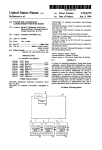
Models PS/PR-1350
Carrier Assembly, Pinion Mount Wet Disc Brakes,
NoSPIN Differential Option, Differential Lock Option
EF
I
f
I
rts supplier. The use of non-original equipment replacement parts is not recommended as their use may cause unit failure
and affect vehicle safety.
"
I
R
EF
ER
EN
C
E
O
N
LY
PAGES 2-7 MISSING
'I t
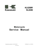
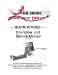
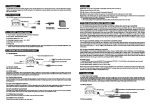
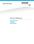
Pinion Disassembly
"
!.r!,
, 18
17
V
\.,'
LY
/
1
@
~'-. ~~
~{\
20 21
ER
EN
C
11 .
12.
13.
14.
15.
16.
17.
18.
19.
20.
21.
Bearing Cup (Pinion Inner)
Bearing Cone (Pinion Inner)
Pinion
Bearing Assembly (Straight Roller)
Shim (Pinion Position)
Steering Cylinder Socket (Optional)
Slotted Nut
Cotter Pin
Carrier Sub-Assembly (Steering)
Flat Washer
Locknut
R
1. Remove pinion cage cap screws which hold pinion
assembly to the carrier housing.
Ct
8
2. Remove pinion and cage assembly from carrier
housing. If difficulty is encountered in removing pinion
assembly from carrier housing, place brass drift on
inner end of pinion gear and tap lightly.
NOTE: Retain shims for possible use during
reassembly.
~
1 ~
J
EF
1. Pinion Nut - Slotted (Required Self,
Locking with 2-Speed Range Box or
Pinion Mount Wet Disc Brake)
2. Cotter Pin
3. Flat Washer
4 . End Yoke or Companion Flange
5. Oil Seal (Not Req. w/Pinion Wet Brake)
6. Bearing Cone (Pinion Outer)
7. Hex Bolt
8. Bearing Cup (Pinion Outer)
9. Bearing Retainer Cap
10. Pinion Bearing Spacer
I ~
I
E
19
10
O
N
/
l ~
.,.",.
,.
~
~
--
I
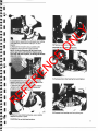
10. Remove outer pinion bearing cup.
E
CAUTION: Do not nick bearing bore.
ER
EN
C
3. Mount pinion assembly in a soh jawed vise, holding
yoke stationary, and remove cotter pin, nut, and
washer.
4. Remove the end yoke using a suitable puller.
5. Remove pinion gear from cage assembly.
NOTE: It may be necessary to tap outer end of
pinion gear with a soft hammer. Replace pinion
nut, flush with end of pinion, so damage to threads
does not occur.
O
N
LY
I
I
I
I
I
-..
11. Remove pinion roller bearing from end of pinion.
6. Located between pinion bearings is a selective
spacer, used for pinion bearing preload. Retain this
spacer for possible use in reassembly.
7. Remove old pinion oil seal and discard . Always
replace it with a new seal at time of reassembly.
8. Lift out outer pinion bearing cone.
EF
I
I
R
I
I
I
.j
. ~ ..,
12. Remove inner bearing cone from pinion gear.
'Re,mc)Ve inner pinion bearing cup, use a suilable
adapter and press or puller.
CAUTION: Do not nick bearing bore.
9
-- -- -
- -
- - -- - - - - - -----,.,J
•
O
N
LY
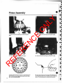
Pinion Assembly
E
5. Install outer pinion bearing cup into pinion cage.
EF
,
2. Press roller bearing onlo the pinion gear.
R
I'
4. Install inner pinion bearing cup inlo pinion cage.
ER
EN
C
1. Press inner pinion bearing cone onto the pinion
gear.
3. Stake roller bearing in six places, using staking tool.
NOTE: Make sure all cage bores are free. of nicks,
dirt, or any contamination.
10
•
6. Use a feeler gauge or shim stock (_0015 Approx.) to
ensure bearing cups are completely seated in bearing
bores. This is necessary for proper pinion position.
I
10. Inspect end yoke or flange seal surface for grooves
caused by lip of seal. If grooves can be detected with
fingernail , it should be replaced .
11. Install end yoke onto pinion, without seal, and
torque to 325 ft. lbs. (400 N·M) so bearing preload can
be checlied.
NOTE: Pinion cage should be rotated while
tightening pinion end nullo seat and align the
pinion bearings.
LY
I
I
t
7. Place selective preload spacer,lhat was removed
during disassembly, onto pinion.
E
,I
ER
EN
C
I
12. To measure preload, clamp flange horizontally in a
soft jawed vise. Wrap a strong cord around pinion
cage. Attach end to spring scale. Read scale only while
pinion cage is turning. Scale reading or bearing
preload must be between 5:14 Ibs.
NOTE: When preload reading does nol fall wlthfn
allowable limits, bearing load can be increased by
using a thinner spacer or decreased by using a
thicker spacer•
•001" (.025 mm) change in preload spacer
thickness, changes scale reading by
approximalely 10 Ibs.
I
~l
I
lilt
. 1
lilt
lilt I
~
R
~
8. Place pinion cage onto pinion gear inner bearing.
EF
'~" I
'" I
The pinion spacers are available in the following
thicknesses. Measure the spacer before assembly to
assure correct thickness.
INCHES
.5135
.5165
.5195
.5225
.5245
.5255
.5265
.5275
.5284
.5295
.5305
M.M.
13.04
13.12
13.19
13.27
13.32
13.35
13.37
13.40
13.42
13.45
13.47
INCHES
.5315
.5325
.5335
.5345
.5355
.5375
.5395
.5405
.5435
.5485
M.M.
13.50
13.52
13.55
13.58
13.60
13.65
13.70
13.73
13.80
13.93
NOTE: Closer adjuslment can be made by working
next thinner spacer to desired thickness using
emery clolh on a flat surface.
~/
9. Instalt outer pinion bearing cone onto pinion.
t
O
N
J
CAUTION: Wash spacer thoroughly of emery
cuttings before installing on pinion.
11
R
EF
ER
EN
C
E
O
N
LY
PAGES 12-17 MISSING
LENGTHWISE
BEARING
ARC
1__ _
ROOT
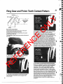
3. If the pattern is concentrated more toward the heel
(as shown above). backlash must be reduced.
Recheck backlash as described in step 6. page 17. To
reduce backlash, loosen the right side adjusting ring
until the measured backlash is within specification. The
tooth contact pattern should now have the sarne
general shape and location as shown in step 2. If the
contact pattern still does not conform, less backlash
than normal is required . To avoid reducing difterential _
bearing preload excessively, further loosening of thE" ..
right hand adjusting ring should be accompanied by " _Y
equal tightening of the left hand adjusting ring. Place a
dial indicator direclly on each adjusting ring to measure
the exact amount of additional adjustment. Decreasing
backlash moves the ring gear toward the pinion.
ER
EN
C
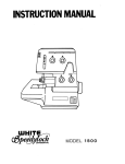
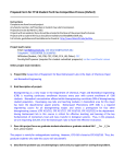
Gear tooth nomenclature
The toe of the gear toolh is the portion of Ihe tooth
surface at the end towards the center.
The heet of the gear tooth is the portion of the tooth
surface at the outer end.
The top land of a gear tooth is the surface of the top of
the tooth.
O
N
~.L- _____
E
HEEL
LY
Ring Gear and Pinion Tooth Contact Pattern
R
EF
1. Paint ring gear teeth with marking compound and
rotate with pinion to obtain contact pattern.
4. If the patlern is concentrated at the toe (as shown
above), more backlash is required . Recheck backlash.
To increase backlash, tighten the right side adjusting
ring further until the measured backlash is within
specification. The tooth contact pallern should now
spread across the ring gear tooth as in step 2. tf the
contact pallern slill does not conform, more backlash
than normal is required. To avoid increasing differential
2. The tooth contact patlerns should have the same
general shape and position as the ring gear teeth
shown above.
18
bearing preload excessively, further tightening of th'lr -..
right hand adjusting ring should be accompanied by
,
equal loosening of the left hand adjusting ring . Place a
dial indicator directly on each adjusting ring to measure
the exact amount of the additional adjustment.
Increasing backlash moves the ring gear away from
the pinion.
\
I
I
LY
O
N
E
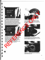
6. If pattern is concentrated at the tooth top land (as
shown above), the pinion is too far away from the ring
gear and must be moved closer to the ring gear to
establish its proper mounting distance and tooth
contact pattern. This is accomplished by selecting a
thinner pinion bearing cage shim. Readjust
pinion-to-ring gear backlash as required once proper
mounting distance has been established.
8, On axles equipped with the differential lock option,
install the stationary collar onto the splined end (flange
half), of the differential support case.
R
I
I
I
7. After proper ring gear pattern is achieved, again
torque the differential bearing cap bolts to 150-160 ft.
Ibs. (200-220 N-M) . Install adjusting ring retainers and
new cotter keys of proper size.
ER
EN
C
I
I
5. If a pattern is concentrated at the ring gear tooth root
as shown above, the pinion is too close to the ring
gear. It must be moved out and away to establish its
proper mounting distance and contact pattern as
shown in step 2, page 18. This is accomplished by
choosing a thicker pinion bearing cage shim. Readjust
pinion-to-ring gear backlash, as required . once proper
pinion mounting distance has been established.
EF
I
I
I
I
I
I
I
\
•
9_ tnstall spiral locking ring into groove on splined end
of differential support case.
19
J
.
.~
I
I
I
I
I
I
I
ER
EN
C
E
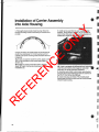
2. Apply Permatex #2 gasket sealer to axle housing at
carrier mounting flang e. A 1/4 inch bead around the
outside of all carrier mounting studs and each stud hole
is required.
3A. If studs are used to mount Ihe carrier. apply Loctite
#271 or its equivalent to the threads and torque to
30-50 ft. Ibs.
3B. If bolts are used to mount the carrier. thread 2
studs 180· apart. into the axle housing as an
installation aid.
4. Install carrier assembly into axle housing. Install
washers. Torque bolls to 56·62 ft . Ibs_ or lock nuts to
49-54 ft. Ibs. Bolls and locknuts must be cleaned and
coated with Loctite #271 , or its equivalent.
O
N
1. Thoroughly clean inside of axle housing. Slone the
housing mounting surface if necessary to remove bUrrs
or nicks.
LY
Installation of Carrier Assembly
into Axle Housing
R
EF
4B. If axle is equipped with differential lock, insert s l i .
collar into axle housing and engage on axle shaft
•
spline prior to carrier assembly installation.
5. Assemble axle shafts, hubs, brakes, and all wheel
end paris at this time following procedures outlined in
the PS-PR 1350 Wheel End Manual .
6. Clean drain plug and install. Fill unll with proper
hypoid gear lubricant to same level as fill hole located
in bowl of axle housing.
•
20
- - - - -- - -- - -- - - - - - -.-------- -- - --
I
I
I
I
I
I
I
...j
I
I
")
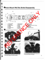
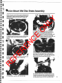
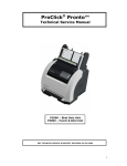
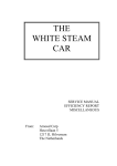
.inion Mount Wet Disc Brake Disassembly
I
I
I
I
I
I
I
20
11
9
B. Sialionary Disc
9. Rotating Disc
to. Piston
11. O-Ring
12. O-Ring
13. Oil Seal
14. Power Plate
8
ER
EN
C
1. Heax Head Bolt
2. Flat Washer
3. Sealing Washer
4. Oil Seal
5. Housing
6. Hex Socket Plug
7. O-Ring
I
10
O
N
12
5
o
17
6
15. Bleeder Screw
16. Orifice Insert
17. End Yoke or Companion Flange
1B. Flat Washer
19. Pinion Nul
20. 12 point Cap Screw
E
13
.)
_emove drain plug and drain hydraulic oil.
EF
,.
4. Remove housing to power plale bolts.
2. Remove pinion nut and washer.
R
I
I
I
I
I
I
1
LY
3 2
\. \
"
. ../
3. Turn assembly to vertical position as shown. and lift
pinion yoke or flange out of carrier assembly.
5. Lift housing off power plale assembly. Inspect outer
O-ring seal and replace if damaged.
21
LY
O
N
9. Lift power plate away from pinion bearing cage
assembly.
IMPORTANT NOTE: BEFORE
INSTALLING REPLACEMENT INPUT
YOKE SEALS, THOROUGHLY CLEAN
EACH BORE. APPLY A THIN
UNIFORM COATING OF #2
PERMATEX TO BORE WALLS.
CAREFULLY INSTALL NEW SEALS •
UNTIL FLUSH, MAKING SURE LIP
DIRECTION IS THE SAME AS THE
ORIGINAL SEAL.
R
EF
ER
EN
C
(rounded) brake discs and clean thoroughly with
suitable petroleum base solvent. Inspect rotating discs
for wear in the involute splines. Replace jf worn. If OK,
measure Ihickness of bonded friction material. wilh 0·1 "
micrometer. I( discs measure less than .240 in. (6.1
mm) they must be replaced. Replace all seals when
replacing bonded discs.
Inspect stationary discs for warpage using a straight
edge. If warpage is indicated discs must be replaced.
Inspect all brake discs for heat damage. Replace if
necessary.
NOTE: tf brake discs are within specifications, and
the assembly was operating, inner hydraulic piston
seals do not need replacing . However if discs need
replacing, replace piston seals also.
7. To replace piston seal, direct piston away from
operator. apply low air pressure (15Ibs. maximum) into
hydraulic inlet.
CAUTION: If high pressure Is applied, the piston
may "pop" out with considerable force. Also avoid
spray of hydraulic fluid.
Remove old O-rings. Clean thoroughly and replace
with new seals.
E
6. Remove both stationary (steel) and rotating
8. To replace pinion seal, or repair carrier assembly, it
will be necessary to remove power plate. Remove
power plate to carrier bolts as shown.
22
.
,"-.~-
I
I
LY
O
N
E
ER
EN
C
1. Sel power plale inlo posilion on pinion bearing cage
assembly. Make certain hydraulic inlel is al proper
position.
4. Posilion and align brake discs belore inslalling
housing (cover). Position slalionary (sleel) disc lirst.
Allernale remaining rotating (bonded) discs and
slalionary discs as shown. Inslall2 housing bolls, 1800
apart, aligning stationary discs. Slide yoke (flange)
slowly onlo pinion splines, rolaling from lefllo righl unlil
center splines in rotating discs line up correctly.
5. Remove yoke and inslall ouler O-ring seal onto
2. Bolls allaching power plate to carrier assembly must
be cleaned and coated wilh #271 Loctite or its
equivalent.
power plate in seal register. lube wilh hydraulic fluid .
Inslall housing as shown. Visually align boll holes and
position drain hole on bottom side of carrier.
R
I
I
I
I
I
I
J
I
I
I
I
I
I
I
NOTE: All parts must be thoroughly cleaned before
reassembly. Replace necessary seals and a-rings
at this time. lubricate all seals and a-rings wilh
hydraulic fluid .
EF
I
'inion Mount Wet Disc Brake Assembly
I
3. Torque bolls 10100-125 fI. lbs. (135-162 N-M).
6. Install flat washers and new sealing washers onto
housing to power plate bolts. Coat threads with #271
Loclite or its equivalent. Install bolts through housing
and alternately torque to 20-25 fl. Ibs. (26-32 N-M).
23
_. .- -
_. --~..,.
I
r: ~
• .----m
8. After assembly has been installed into the vehicle. it
will be necessary to bleed hydraulic system. and either
fill. or hook up cooling lines to cooling section of wet
disc brake. Follow procedures outlined in vehicle
•
R
EF
ER
EN
C
maintenance manual.
E
7. Install yoke (flange) and torque pinion nut to 325 ft.
Ibs. (440 N-M).
O
N
LY
I~
•
24
I
I
I
~
~
~
~
....
,'~
~
I
~ I
I
~ I
." I
I
I
~
~
~
Description
The NoSPIN differenlial provides equal amounts of
drive tin e torque to both right and len driving wheels
and also permits differential action for turning corners.
The unit is installed in the differential case in place 01
conventional gears, pinions and spider. The action of
the unit is the same for both drive and coast loads.
CAUTION: Turn the engine off and raise all driving
wheels of a·NoSPIN differential equipped axle
when servicing wheels, brakes, axles or tires to
prevent the.vehicle from moving. Axles equipped
ith NoSPIN differentials deliver power to both
heels - eye" when only one wheel is on the
•
ground. Failure to observe these cautionary
measures may cause the vehicle to move which
can result in damage or injury.
Routine Inspection
Carefully follow th e recommended lubrication,
preventative maintenance and inspection procedures
of the vehicle/manufacture as part of NoSPIN
diHerenlial preventative maintenance. Except for
lesling for proper operation, and a possible change in
the way brake adjustments are made (as explained
below), maintenance. inspection and lubrication
requiremenls of NoSPIN differential equipped vehicles
are lhe same as for vehicles wilh standard differenlials.
~
I
;*
4 Spring Retainer
5 Side Gear
Differential Removal
1. With carrier mounted in a holding fixture, remove
adjusling nut lock. and mark position of adjusting nut
for proper adjustment when reassembling. Bearing
saddles must be replaced in original position. Mark as
shown above. Remove bearing saddle bolls and lift
ring gear and differential clear of carrier.
Check for Proper Operation of NoSPIN Differential
At 90 day intervals, the drive axles should be raised
and the NoSPIN differenlial checked (see page 29) 10
be sure it isoperating properly. This test will also
determine if bolh axle shafts are intact.
Brake
When making brake adjustments, the wheels on both
sides of the vehicle must be raised and the
transmission placed in neulral so that the ring gear and
opposite wheels are free to rotate with the wheels on
the side being adjusted.
R
,,
,
,
1 Spider Assembly
2 Clutch Member Assembly
3 Spring
O
N
~
0
E
~
I
ER
EN
C
~
I
EF
I
I
I
I
I
I
I
LY
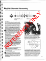
'~ 4JoSPIN Differential Disassembly
; ~rVIClng NoSPIN Differentials
..
y decision to disassemble the axle for inspection
ould be made only after performing the operation
tests staled on page 29 and after consulting the trouble
shooting guide on page 30 and determining that the
NoSPIN diff~rential. or some other axle part, is not
working properly.
2. A retaining bolt and washers are useful to keep the
NoSPIN differential assembly intact when removing it
from Ihe differential case and when reinstalling it in th e
axle housing. You will note that the retaining washers
must be small enough to pass through the case ends
(dimension "A"), yet large enough to restrain the two
side gears (dimension " B") and the balance of the
NoSPIN differential assembly when all parts are
assembled and the springs are compressed.
25
Cleaning and Inspection
•
Wash all parts thoroughly with clean, non·flammable
solvent Inspect all mating surfaces and splines for
possible wear or damage. Replace all worn or
damaged parts before reassembly . Springs should
have a compressed operating height of .620 inch at 88
load pounds ± to%. Replace with new springs if not
within these specifications.
.:
.::
~
I~
•
R
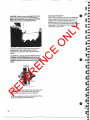
4. If retaining bolts and washers were used, mount unit
in a small press as shown and remove nut. Slowly
release press until spring pressure is released.
5. Remove side gears, springs, spring relainers , driven
clutch assemblies and spider assembly.
•
26
I::
I~
EF
ER
EN
C
CAUTION: If a retaining bolt and washers are not
available, hold the differential case firmly as the
last bolts are being removed from the case halves
to absorb spring pressure and prevent possible
Injury.
I
-""
E
3. Mark the differential case halves so they may be
reassembled in their original position, remove
differential case bolls and nuts and separate case
halves.
O
N
LY
CAUTION: Failure to use a retaining bolt or some
other restraining means when separating the
differential case halves can cause injury. NoSPIN
differentials contain compressed springs.
I
F
•
I
')
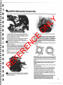
... ~oSPIN Differential Assembly
I
I
I
I
,.., I
I
I
~
~.,'
,,"
LY
.
~
~
~-:J
.
~
~
~
~
I
I
I
I
I
I
I
R
~
.
Am
..,.. J
I
I...
7. Assemble driven clutch assembly over the spring
with the teeth up.
NOTE: Verify that the spring Is functioning freely
by compressing the driven clutch over the side
gear splines. Be sure the spring is not binding and
that there is good contact between end coil and
retainer when driven clutch and side gear splines
are fully meshed,
8. Position the spider assembly over the driven clulch
assembly.
ER
EN
C
~
1. Wash the differential case, ring gear, dilferential
case bolts and nuts, and bearing assemblies, in clean,
non lIammable solvent. Inspect for damage, wear, or
corrosion. Replace if necessary.
2. Inspect axle shafts for excessive wear or damage.
Fit axle shaft into side gear of NoSPIN to insure
smooth, tight fit. If either the axles or side gears are
they must be replaced .
....Posilion the ring gear and differential case half as
shown in slep one.
NOTE: To protect bearing. during the following
steps, Install bearing cup on bearing cone,
4. Lightly lubricate inside 01 dilferential case and install
smooth ground hub 01side gear inlo bore of diHerential
case. Be sure the side bearing will rota Ie freely in the
case.
5. Assemble spring retainer over the side gear splines
with the retaining lip (outside diameter) down.
EF
~
E
~
O
N
~
APlace spring over the side gear spline and against
~ retainer lip with the smaller diameter of the spring
against the retainer.
SpidlH K.,
IMPORTANT: Be sure the slot in the hold out ring Is
properly aligned over the long tooth of the spider.
9. Place the remaining driven clutch assembly onto the
spider.
NOTE: Again be sure the slot in the hold out ring is
properly positioned over the long tooth of the
spider.
10. Assemble the remaining retainer, spring , and side
gear as in step #6.
11 . Mount the plain case half over the side gear and
compress the springs, be sure side gear splines are
competely meshed with Ihe driven clulch splines.
12. Hold the case halves firmly together, aligning
marks, and start at least 2 case bolts 180" apart. To
compress Ihe springs in Ihe NoSPIN, a press can be
used to aid assembly.
CAUTION: 00 not release pressure until bolts are
started and spring pressure has been salely
contained. Failure to follow procedure could
release case halves under extreme pressure.
27
O
N
LY
I
13. Inslall the remaining differential case bolts and
torque to 80-90 ft. Ibs. (108·122 N·M).
•
R
EF
ER
EN
C
E
14. Install ring gear, and differential case into carrier
lollowing procedure in differential assembly section of
this manual.
•
28
- - _ ._ - _ .. _ --
-
- - -- - -- - - -
F. - - -- - --
I
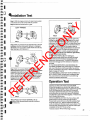
: ttnstallation Test
I
~
I
I
"" I
I
,., I
~
LEFT WHEEL
Step 3 With an assistant on the opposite side, start the
installation test by rotating both wheels in a forward
direction as far as possible, (Both wheels should stop
after rotating a short distance.)
,
I
I
~ I
I
I
I
I
~
ER
EN
C
~I
~,) .
'
~
Step 4
Step 4 With an assistant firmly holding the right
wheel forward (against the stop), rotate the left wheel
rearward while listening for an indexing or clicking
sound, (The right wheel must be held firmly against the
stop or the left wheel will not disengage freely.) Grasp
the left wheel to stop its rotation, and move it slightly
forward (in the direction of the stop). The NoSPIN
differential should lock up.
R
~
reversed.
EF
~
~'J
I
Step 6 With the assistant on the opposite side firmly
holding the right wheel rearward (against the stop),
rotate the left wheel forward, again listening for an
indexing or clicking sound, (Again, the right wheel must
be held firmly against the stop or the lelt wheel will not
disengage freely.) Grasp the left wheel to stop its
rotation, and move it slightly rearward (in the direction
of the stop), The NoSPIN differential should lock up,
REPEAT STEPS 3, 4, 5 and 6, except hold the left
wheel against the stops and rotate the right wheel,
in both forward and reverse.
IF PROPERLY INSTALLED, the rotating (or
overrunning) wheel should cam out easily by hand,
rotate freely in both directions and produce a soft
indexing or clicking sound, The NoSPIN differential
should not reengage until the direction of rotation is
E
Step 3
O
N
Step 6
LY
Step 1 With the engine turned off, raise driving axle(s)
until all tires are out of contact with any surface,
Step 2 Place the transmission in gear,
Step 5
Step 5 Rotate both wheels rearward as far as
.ssible. (Both wheels should stop after rotating a
distance,)
wort
IF YOU HEAR REPEATED LOUD INDEXING OR
CLICKING SOUNDS when performing this installation
test, one of the driven clutch assemblies may not be
properly assembled to the spider. Recheck installation
steps on pages 27 and 28,
IF EITHER WHEEL DOES NOT ROTATE FREELY IN
BOTH DIRECTIONS, recheck each installation step.
Also, check hand and foot brakes for possible drag
caused by improper adjustment.
Operation Test
Check to see that both wheels of each NoSPIN
differential equipped axle are driving , Make this test
under load, so that engine torque is applied through the
NoSPIN differential with the wheels on the ground,
One way to achieve this load is to drive up against a
solid obstruction (on loose dirt or gravel, if possible)
and attempt to spin both wheels together. 'Perform this
test in forward and reverse .
CHECK CAMMING ACTION, On a lIat surface, with
good traction, drive the vehicle in a tight circle in
forward and reverse to be sure that the outside wheet
is free to overrun (Le " that the outside tire does not
scuff), A clicking or indexing sound may be heard, The
sound of gear reengagement may also be heard upon
completion of the turn, This is normal.
"Exercise Caution When Performing This Test.
29
•
TROUBLESHOOTING THE NoSPIN DIFFERENTIAL
Polenlial problems are slaled on Ihe leh; possible
causes for Ihose problems are lisled, by number, on
Ihe right The explanalion of Ihese "possible causes "
follows below chart.
POSSIBLE CAUSE(S)
1
2
•
• •
driving or tend s to go straight when making turns
•
•
No differential action; binding in turns
•
Hub studs shearing; fear tire scuffing;
axle shaft breakage
Steering difficulty; vehicle pulls on slraight forward
3
•
4
5
6
7
8
•
•
•
Grind ing noises
Continuous "clicking" sound in straight forward driving
•
Excessive backlash in vehicle drivetrain; engine lug
•
•
•
or vehicle surge during turns
•
•
•
•
•
•
•
•
•
•
•
•
• •
•
ER
EN
C
Difficulty in turning vehicle from standing start
Erratic operation of NoSPIN differential; premature
•
wear or failure of NoSPIN differential parts
'NOTE: NoSPlN difle'erma" ..... Memil occasional "melal(.c;" 5OU1'Ids d\l9lO backlash bu~1
EF
R
•
",to Urllt This ;s nomlal'
1. Improper installation; defective NoSPIN
differential. Follow lest procedures oullined on page
29. Correcl inslallalion or repair or replace Ihe NoSPIN
differential if Ihe vehicle fails any slep of Ihe test
procedure.
2, Overloading andlor improper weight
distribution. Remove excess weight and redistribute
Ihe load from side to side, according 10 Ihe vehicle
manufacturer's instruction.
3. Unequal rolling radii of the drive tires, A smaller
radius tire will cause the wheel to overrun constantly
when power is applied. The olher lire (with Ihe larger
radius) will do alilhe driving. Replace tires or adjusl tire
pressures un Iii rolling radii are equal.
4. Broken axle shaft. Replace. NOTE: It is possible to
operale a NoSPIN equipped vehicle on one axle shah.
However, Ihis praclice is not recommended in Ihat
serious damage can occur to other axle parts.
5. Bent axle shaft or housing; axle shafts on
different center lines. Replace bent axle shafts or
housing, or realign hub faces and bolt circles in bolh
the differential carrier and axle housing.
6. Larger than normal steering angle; short turning
radius. Vehicles designed wilh high tuming angles
may surge, have sleering difficulty and cause lire wear
during sharp turns. Reduce maximum turning angle
and have the drive decelerate when engine surge
begins.
7. Improper wheel alignment. Correct as required .
30
14
•
•
•
•
•
•
•
•
E
clutch assemblies
13
•
Tendency to side-slip or "fishtail" on icy surface
Sluggish reengagement of NoSPIN differenlial
12
O
N
Excessive driveline noise
10 11
•
• •
•
• • • • •
• • • • • • •
Excessive lire wear
9
LY
PROBLEM
•
•
•
•
•
•
•
•
•
•
8. Worn or defective axle parts. Check the condition
of the ring gear, pinion gear, bearings, seals, etc.
Replace as required .
9, Foreign matter in axle housing or improper
assembly of axle parts. Inspecl for contamination.
Check assembly of axle parts.
10. Incorrect ring and pinion adjustmenls; worn
driveline parts (Iransmission gears, U·joints, etc.).
Replace or adjust parts as required .
11. High crown in road ; poor traction surface under
all drive wheels. The lendency 10 side·slip or " fishtail"
on icy surface sloping toward the curb is more
pronounced when using a traclion differenliallhan
when using a convenlional differenlial. Stability can be
retained when side-slip occurs by deceleraling (Ielling
off the acceleralor). CAUTION: Do not apply brake.
To do so may result in loss of vehicle control.
12. Heavy gear lubricant. In sub· zero lemperatures,
gear lubricant can Ihicken and impede the normal
funclion of Ihe NoSPIN differenlial. Spicer
recommends thaI the axle oil be changed lor cold
wealher opera lion 10 Ihe lighlesl acceplable lubricant.
Such as 75W, 75W-90, or 75W-140. Heal conlrol
devices, garaging and a warm-up period may also
provide relief from Ihis problem.
13. Low cylinder pressure, undersized cylinder, •
excessive angle of articulation, excessive vehicle
weight. Correcl as required.
14. Improper application of product. Review
application guidelines of vehicle manufaclurer.
t""
I
,.., ':}
I
..
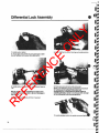
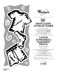
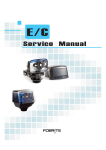
" ifferential Lock Disassembly
~
~ I
fill} I
pill)
,.., I
LY
20
O
N
~
~
~
I
,.., I
,."
....,"", .~
\
.
~I
~
'~I
"
~
~
~
~
I
I
I
I
I
1. Indicator Switch
2. Screw (Guide)
3. Jam Nut
4. Spring Retainer
5. Spring
6. Rod
7. Fork
8. Bushing
9. Hex Bolt
1O. Flat Washer
t 1. Piston
12. Oil Seal
t 3. Shaft (Pivot)
14. Shifter Housing
15. Diff. Case (Flange Half)
16. Collar (Stationary)
17. Retaining Ring (Spiral)
18. Collar (Sliding)
19. Axle Shaft
20. Axle Housing
1. Raise vehicle until wheels of axle with differenlial
lock clear ground. Support with floor stands.
2. Disconnecl drive shaft.
3. Drain oil from axle.
4. Remove steering cylinder to gain access to
differenlial lock shifter assembly.
5. Disconnect hydraulic line and indicator switch wires
from shifter assembly.
R
~
~
~
•
ER
EN
C
'"
I
EF
~
E
~
6. Remove mounting bolts from differential lock shifter
assembly and remove shifter assembly from axle
housing.
NOTE: Removal of the differential lock stationary
and slide collars is covered in the carrier section of
this manual.
31 I
\
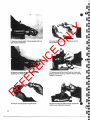
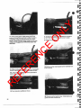
10. Loosen jam nut and remove guide screw from
spring retainer.
ER
EN
C
E
7. Remove indicator switch. Check operation with test
light. Replace if defective.
O
N
LY
•
11. Using a small drift punch and hammer. drive pivot
shaft out of shifter housing. Inspect for wear or scoring.
Replace if necessary.
R
EF
8. Remove complete spring retainerfguide screw
assembly from shifter housing.
9. Remove rod and spring from guide screw.
32
12. Remove fork from shifter housing. Inspect fork
ends for wear. Replace if necessary.
•
.
•
~-----------
V)
~I
i"!t
1
1
.-
•'
-'
LY
'
-- . ~~
..
.," ':
13. Inspect bronze pivot bushings in fOrk. If worn.
replace.
~
I
ER
EN
C
~
E
iI!'9
"""'~
"""
..;
.
"...
I
I
"'" I
~
I
I
'" I
~
~
~
~
~
NOTE: It may be necessary to apply compressed
air through the hydraulic inlet to aid piston
removal.
CAUTION: Stay clear from inside area of shifter
housing when applying compressed air to avoid
personal injury. Place a shop towel inside the
shifter housing to restrict piston travel and prevent
damage to the piston. USE ONLY 15 PSI MAX. AIR
PRESSURE.
15. Inspect oil seal on pislon. Replace if necessary.
R
~
14. Remove piston from shifter housing.
EF
~
O
N
,..1
----_.-
16. Inspecl piston and piston bore in shifter housing. If
either is pitted or scored. replace.
1
eJ
I
33
•
E
5. Insert shift fork in shifter housing and install pivot pin.
ER
EN
C
1. Install seal on piston.
2. Thoroughly clean shifter housing and apply a light
coat of hydraulic oil to piston bore and piston.
O
N
LY
Differential Lock Assembly
3. Install piston into piston bore until recessed approx.
1/8".
EF
NOTE: USe 01 a piston Installing tool (Dana tool
#451063), is recommended to prevent damage to
the oil seal.
6. Stake area around both ends of pivot pin.
NOTE: The lollowlng steps outlined the procedure
lor setting·up the proper diHerentiallock
engagement. It is important that these steps be
closely followed in order to avoid possible damage
to the diHerentiallock during operation.
R
4. Install new bushing into shift fork if required .
7. Install indicalor switch into gUide screw and
34
ER
EN
C
•
11. Install spring retainer/guide screw assembly into
shiMer housing and tighten.
E
8. Thread jam nut onto guide screw until bottomed
against screw head .
O
N
LY
•
12. Apply #2 Permatex to shiMer housing flange. Install
shiMer assembly on axle housing. Make sure fork
engages groove in slide collar.
NOTE: The installation of the diflerentlallock
stationary and slide collars is covered in the carrier
section of this manual.
R
EF
9. Thread guide screw into spring retainer approx.
three turns.
I
•
Insert rod into guide screw. DO NOT INSTALL
RING AT THIS TIME.
13. Install flat washers and mounting bolts. Torque to
44-48 M. lbs.
35
LY
O
N
17. Thread jam nut against spring retainer and torque
to 100 ft. Ibs. DO NOT allow guide screw to rotate.
18. Remove air pressure.
ER
EN
C
E
14. While rotating pinion, apply approx. 50 PSI air
pressure through hydraulic inlet in shifter housing to
completely engage mating diHerentiallock collars.
NOTE: Check individual wheel rotation to be sure
collars are enagaged and differential action has
beenlosl.
19. Remove spring retainer/guide screw assembly from
shifter housing.
15. While continuing to apply air pressure, thread guide
screw in until it stops, indicating rod contact with fork.
".
:.
R
EF
15A. Attach test light to indicator switch terminals to
verify rod is contacting fork.
16. Turn screw in an additional 116 turn.
20. Remove rod lrom guide screw. Install spring over
guide screw and re-install rod.
36
F.
I
I
I
I
I
i'IIIt I
I
•
22. Loosely connect hydraulic line to shifter housing
and bleed air from line.
23. Tighten hydraulic line and connect wires to
indicator switch.
24: Actuate differenliallock from cab of vehicle and
verify engagemen t with indicator light.
25. Install steering cylinde r.
LY
'}
26. Connecl drive shaft and lower vehicle.
27. Refill axle to correct level wilh proper lubricant.
(Refer to lubricant section of this manual).
~
~
21 . Install complete spring retainer/guide screw
assembly into shifter housing and torque to 100 ft . Ibs.
~
~
••
•I
•
•
•
..,.•
E
~
~J
~ '
jIIII'\
~
~
~
jIII\
~
~
~
~
R
~
~
~
EF
~
ER
EN
C
~
~
O
N
~
iI'I)
~J
.., •
...
~
!iI!)
37
•
Inspection and Failure Analysis
Fracture of ring gear teeth at the
looth loe.
Scored and/or scufled ring and
pinion gear teeth.
RECOMMENDED REPAIR
1. ExceSSive loading of the gear beyond design intent .
Replace ring gear and pinion as matched set.
2. Incorrect gear adjustment (excessive backlash).
Carefully follow the recommended procedures for
adjusting ring gear and pinion backlash and tooth
pattern.
1. Shock impact loading.
Replace ring gear and pinion as matched set.
O
N
Fracture of ring gear teeth at the
tooth heel.
PROBABLE CAUSE
2. Incorrect gear adjustment (insuHicient backlash) .
Carefully tollow the recommended procedures for
adjusting ring gear and pinion backlash looth pattern.
1. InsuHicient lubrication
Replace nng gear and pinion as a matched set.
Replace pinion beatings laking care to set ring and
pinion position and bearing preloads properly.
2. Contaminated lubricant.
E
FAILURE MODE
LY
This section is intended to serve as a gUide for describing and explaining commonly encountered axle problems or
failures, and for recommending appropriate repair procedures.
3. Wrong lubricant or lubricant with depleted additives.
ER
EN
C
4. Worn pinion bearings which result in pinion end play
and incorrect ring and pinion looth contact.
Overheated ring and pinion gear 1. Prolonged operation at excessive temperatures.
teeth. Look lor discoloration 01
2. Incorrecllubricanl.
the gear teeth.
3. Low oil level.
Use correct lubricant, fill to proper level and change at
recommended inlervals.
Replace ring and pinion as a matched set.
•
Use correct lubricant, fill to specified level and change
at recommended intervals.
4. Contaminated lubricant.
All olthe above can result in inadequate lubricant film
between tooth surfaces which causes surfaces to
overheat due to excessive friction.
PitIed drive pinion teeth.
Bent axle housing.
1. Extremely severe service.
Replace ring gear and pinion as a matched set.
2. Insufficient lubrication .
Use correct lubricant, fill to proper level and change at
recommended intervals.
1. Vehicle overloading.
Replace axle housing .
2. Vehicle accident.
EF
3. Shock loading.
Worn or pitted bearing.
R
Leaking oil seal.
1. Insuflicientlubrication.
2. Conlamina\ed lubrtcant.
3. Very severe service.
4. Normal wear.
Use correct Il:Ibricant, lill to proper level and change at
recommended levels.
1" Prolonged operation at excessive oil temperatures.
Replace the oil seal and mating surface if damaged.
2. Scored or dented yoke wear surface.
Use correct lubricant, fill to proper level and change at
the recommended intervals.
3. Improperly installed oil seal.
4< Nicked or cut seal lip .
5. Contaminated lubricant.
(continued on nexl page)
38
Replace bearing cups and cones in matched sets.
Check roller ends lor excessive wear by comparlOg
used rollers with a new bearing.
•
•
- - ---
I
) .. ,etnspection and Failure Analysis
I
~
I
'~" I
~
3. Pinion endplay.
Replace the ring gear and pinion as a matched sel if
necessary.
Fracture..ot differential Side
gears and pinion males.
Shock loading of differential components.
Scoring andlor seizure of cross
shatt arms and pinion mate
gears.
~
3. Extremely severe service.
4. Unequal tire pressures.
Scored or worn thrust washer
surfaces.
Worn pinion roller bearing
retainer bore.
Replace differential side gears, pinIOn males, cross
shaft and thrust washers as a set.
Use correct lubricant, fill 10 proper level and change at
recommended intervals.
Replace differential side gears and pinion males as a
set. Replace wom axle shafts .
Replace any scored washer and anywashef that is
.005 inch thinner than a new one.
Use correct tubl'icanl, fiJI to pmper level and change at
recommended intervals .
1. Severe servica.
Replace carrier housing.
Check pinion for excessive endpJay.
3. Inadequate lubrication.
Use correct lubricant, fill to proper Jevel and change al
recommended intervals.
4. Contaminated lubricant.
Twisted or broken axle shaM.
Severe vehi<:le operation.
Fractured axle shaM al the
l1ange.
1. Loose wheel bearing.
Replace the shaft.
2. Bent axle housing .
Check housing distortion . Make certain thaI wheel
bearings are not worn or misadjusted.
3. Loose shaMto wheel hub bolts.
Replace the shaM.
R
~
Replace differential side gears, pinion males. and
cross shaft as a set.
2. Excessive pinion end play.
EF
~
1. Insufficientlubricalion.
2. Improper lubrication.
3. Contaminated lubricant.
~
~
Replace the ring gear and pinion as a matched set.
1. Excessive wheel spinning.
2. Inadequate lubrication .
Severe service.
1
'" I
11'1
II!!\ I
II!!\
1
1
I
e
e I·
j
e
e
Replace the end yoke.
Check the pinion spline for excessIVe wear.
Severe service.
II!!\I .....
~
~
1. Severe service.
2. Loose pinion nul.
Fatigue fraclure of the pinion
gear teeth. Look rorclear-cut.
wavy fracture lines
(beachmarks) .
~
""~
iI!iI
LY
looseness.
RECOMMENDED REPAIR
O
N
~
Excessive end yoke spline
PROBABLE CAUSE
E
~
FAILURE MODE
ER
EN
C
1
"" I
I
"" I
~
1
•
39
•
•
Diagnosis of Rear Axle Problems
Noise on Drive
1. Excessive pinion to ring gear
backlash,
2. WOIn pinion and ring gear.
3. Worn pinion bearings.
4. loose pinion bearings.
5. Excessive pinion end p lay.
6. Worn differential bearings.
7 . Loose diHerenlia! bearings.
8. Excessive ring gear run-ou\.
9. low tubricanllevel.
10. Wrong or poor grade lubricant.
11. Benl ax le housing.
Noise on Coast
RECOMMENDED REPAIR
1. Adjust
2. Replace
3. Replace
4. Adjust
5. Adjus t
6. Replace
7. Adjust
8. Replace
9. Replenish
10. Replace
11. Replace
LY
PROBABLE CAUSE
O
N
FAILURE MODE
1. Axle noises heard on drive will
usually be heard on coas t,
1. Adjust or replace
(See above)
E
although not as loud.
2. Pinion and ring gear 100 light
2. Adjust
IntermIttent
Noise
ER
EN
C
(audible when decelerating and
disappears when driving),
Constant Noise
1. Flat spot on pinion or ring
gear leeth.
2. Flat spot on bearings.
3. Worn pinion splines.
4. Worn axle shaft dowel holes.
5. Worn hub studs.
6. Benl axle shaft.
1. Worn differential side gears
and pinions.
2. Worn differential spider.
3. Worn diHerenUallhrust
washers.
4. Worn axle shalt splines.
1. Replace
2. Tighten
1. Replace
2.
3.
4.
5.
6.
Replace
Replace
Replace
Replace
Replace
•
1. Replace
2. Replace
3. Replace
4. Replace
R
EF
Noisy on Turns
1. Warped ring gear.
2. Loose differential case bolts.
•
40
LY
O
N
E
ER
EN
C
EF
R
~
e I
~~-----~
E
ER
EN
C
EF
R
O
N
LY
, I
•