1
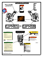
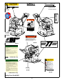
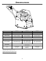
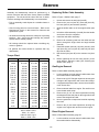
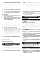
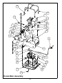
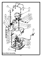
OPERATOR’S SAFETY
AND SERVICE MANUAL
GPR65,
GPR68 &
GPR77
This manual covers the following serial numbers
and higher for each model listed:
GPR65. . . . . . . . . . . . . . . . . . . . 6500001
GPR68. . . . . . . . . . . . . . . . . . . . 6800001
GPR77. . . . . . . . . . . . . . . . . . . . 7700010
REVERSIBLE PLATES
MBW, Inc.
MBW (UK) Ltd.
MBW FRANCE S.A.R.L.
250 Hartford Rd • PO Box 440
Slinger, WI 53086-0440
Phone: (262) 644-5234
Fax: (262) 644-5169
Email: [email protected]
Website: www.mbw.com
Units 2 & 3 Cochrane Street
Bolton BL3 6BN, England
Phone: 01204 387784
Fax: 01204 387797
Z.A. d’Outreville
11 rue Jean Baptiste Néron,
60540 BORNEL, France
E-mail: [email protected]
Website: www.mbw.com
Phone: +33 (0) 3 44 07 15 96
Fax: +33 (0) 3 44 07 41 28
L16456 / 09.14.N
©MBW, Inc. 2004
Printed in the USA
TABLE OF CONTENTS
Safety Information . . . . . . . . . . . . . . . . . . . . . . 1
Service. . . . . . . . . . . . . . . . . . . . . . . . . . . . . . . . 9
Introduction . . . . . . . . . . . . . . . . . . . . . . . . . . . . . . . . . 1
Torque Chart . . . . . . . . . . . . . . . . . . . . . . . . . . . . . . . 9
Safety Precautions . . . . . . . . . . . . . . . . . . . . . . . . . . . 1
Replacing Shifter Cable Assembly . . . . . . . . . . . . . . . 9
Safety Decals . . . . . . . . . . . . . . . . . . . . . . . . . . . . . . . 1
Gas Engine Removal . . . . . . . . . . . . . . . . . . . . . . . . . 9
Safety Decal Set #16031 . . . . . . . . . . . . . . . . . . . . . . 3
Diesel Engine Removal . . . . . . . . . . . . . . . . . . . . . . 10
Specifications. . . . . . . . . . . . . . . . . . . . . . . . . . 4
Operation . . . . . . . . . . . . . . . . . . . . . . . . . . . . . 5
Introduction . . . . . . . . . . . . . . . . . . . . . . . . . . . . . . . . . 5
Before Starting & Operating . . . . . . . . . . . . . . . . . . . . 5
Starting Engine . . . . . . . . . . . . . . . . . . . . . . . . . . . . . . 5
Operating . . . . . . . . . . . . . . . . . . . . . . . . . . . . . . . . . . 5
Stopping Engine . . . . . . . . . . . . . . . . . . . . . . . . . . . . . 5
Maintenance . . . . . . . . . . . . . . . . . . . . . . . . . . . 6
Maintenance Schedule . . . . . . . . . . . . . . . . . . . . . . . . 6
Fluid Levels. . . . . . . . . . . . . . . . . . . . . . . . . . . . . . . . . 6
Engine Maintenance . . . . . . . . . . . . . . . . . . . . . . . . . . 6
Engine Speed . . . . . . . . . . . . . . . . . . . . . . . . . . . . . . . 6
Belt Adjustment. . . . . . . . . . . . . . . . . . . . . . . . . . . . . . 6
Exciter Oil Change Procedure . . . . . . . . . . . . . . . . . . 6
Checking the Shifter Cable . . . . . . . . . . . . . . . . . . . . . 7
Exciter Removal . . . . . . . . . . . . . . . . . . . . . . . . . . . . 10
Exciter Disassembly . . . . . . . . . . . . . . . . . . . . . . . . . 10
Actuator Disassembly. . . . . . . . . . . . . . . . . . . . . . . . 11
Shifter Disassembly . . . . . . . . . . . . . . . . . . . . . . . . . 11
Shifter Assembly . . . . . . . . . . . . . . . . . . . . . . . . . . . 11
Actuator Assembly . . . . . . . . . . . . . . . . . . . . . . . . . . 11
Exciter Assembly . . . . . . . . . . . . . . . . . . . . . . . . . . . 12
Parts Replacement Cycles and Tolerances . . . . . . . 13
Replacement Parts . . . . . . . . . . . . . . . . . . . . . 15
Actuator Assembly . . . . . . . . . . . . . . . . . . . . . . . . . . 16
Shifter Assembly . . . . . . . . . . . . . . . . . . . . . . . . . . . 18
Exciter Assembly . . . . . . . . . . . . . . . . . . . . . . . . . . . 20
Honda Main Assembly . . . . . . . . . . . . . . . . . . . . . . . 22
Diesel Main Assembly . . . . . . . . . . . . . . . . . . . . . . . 24
Handle Assembly . . . . . . . . . . . . . . . . . . . . . . . . . . . 26
Warranty . . . . . . . . . . . . . . . . . . . . . . . . . . . . . 28
WARNING
CALIFORNIA PROPOSITION 65 WARNING
Engine exhaust and some of its constituents are
known in the state of California to cause cancer, birth
defects, and other reproductive harm.
SAFETY INFORMATION
Introduction
SAFE DRESS: Do not wear loose clothing,
rings, wristwatches, etc. near machinery.
This Safety Alert Symbol is used to call attention
to items or operations which may be dangerous
to those operating or working with this
equipment.
The symbol can be found
throughout this manual and on the unit. Please read these
warnings and cautions, along with all decals, carefully
before attempting to operate the unit. Make sure every
individual who operates or works with this equipment is
familiar with all safety precautions.
NOISE PROTECTION: Wear OSHA specified
hearing protection devices.
EYE PROTECTION: Wear OSHA specified
eye shields, safety glasses, and sweat bands.
FOOT PROTECTION: Wear OSHA specified
steel-tipped safety shoes.
WARNING
HEAD PROTECTION: Wear OSHA specified
safety helmets.
GENERAL WARNING.
Indicates information
important to the proper operation of the
equipment. Failure to observe may result in
damage to the equipment and/or severe bodily
injury or death.
DUST PROTECTION: Wear OSHA specified
dust mask or respirator.
CAUTION
OPERATOR: Keep children and bystanders
off and away from the equipment.
GENERAL CAUTION.
Indicates information
important to the proper operation of the
equipment. Failure to observe may result in
damage to the equipment.
REFERENCES: For details on safety rules and regulations
in the United States, contact your local Occupational Safety
and Health Administration (OSHA) office. Equipment
operated in other countries must be operated and serviced
in accordance and compliance with any and all safety
requirements of that country. The publication of these
safety precautions is done for your information. MBW does
not by the publication of these precautions, imply or in any
way represent that these are the sum of all dangers present
near MBW equipment.
If you are operating MBW
equipment, it is your responsibility to insure that such
operation is in full accordance with all applicable safety
requirements and codes. All requirements of the United
States Federal Occupational Safety and Health
Administration Act must be met when operated in areas that
are under the jurisdiction of that United States Department.
Safety Precautions
LETHAL EXHAUST GAS: An internal
combustion engine discharges carbon
monoxide, a poisonous, odorless, invisible
gas. Death or serious illness may result if
inhaled. Operate only in an area with proper
ventilation.
NEVER OPERATE IN A
CONFINED AREA!
DANGEROUS FUELS: Use extreme caution
when storing, handling and using fuels, as
they are highly volatile and explosive in vapor
state. Do not add fuel while engine is running.
Stop and cool the engine before adding fuel.
DO NOT SMOKE!
Safety Decals
SAFETY GUARDS: It is the owner's
responsibility to ensure that all guards and
shields are in place and in working order.
Carefully read and follow all safety decals. Keep them in
good condition. If decals become damaged, replace as
required. If repainting the unit, replace all decals. Decals
are available from authorized MBW distributors. Order the
decal set listed on the following page(s).
IGNITION SYSTEMS: Breakerless, magneto,
and battery ignition systems can cause severe
electrical shocks. Avoid contacting these
units or their wiring.
-1-
GPR65 & GPR68
RUN
IDLE STOP
THROTTLE
15843
FORWARD
#15843 Diesel only
REVERSE
14665
#14465
#13484
#12500
01064
#15874 (not included in kit)
OR
16993
16994
#16993 (not included in kit)
1.
2.
3.
4.
5.
6.
7.
8.
GASOLINE PLATE
OPERATING INSTRUCTIONS
Check engine oil level.
Open fuel valve.
Choke engine. A warm engine may not need to be
choked.
Open throttle part way.
Pull starter rope.
After starting: open choke, return throttle to idle
position.
During operation, when excessive kickback is
noticed, maximum compaction has been reached.
To stop, return throttle to the idle position, use
engine stop switch, close fuel valve.
#16994 (not included in kit)
CAUTION
UNLEADED GASOLINE
13481
#13481 Gas only
17287
#17287
WARNING
OPERATION OF THIS EQUIPMENT MAY
CREATE SPARKS THAT CAN START FIRES
AROUND DRY VEGETATION. A SPARK
ARRESTER MAY BE REQUIRED. THE
OPERATOR SHOULD CONTACT LOCAL FIRE
AGENCIES FOR LAWS OR REGULATIONS
19791
RELATING TO FIRE PREVENTION
15866
OR
Machine may fall and cause injury or damage if
lifted improperly. Lift by rollcage only.
GPR65/68:
GPR77:
Gas = 330 lbs (149 kg) Gas = 397 lbs (180 kg)
Diesel = 360 lbs (163 kg) Diesel = 399 lbs (181 kg)
#15866 Gas only
DIESEL PLATE
OPERATING INSTRUCTIONS
#19791
1.
2.
3.
4.
Check engine oil level.
Check fuel level.
Set engine speed control in the middle position.
Move decompression lever (if equipped) to the up
position. (Located on top of the engine)
5. Use key (if equipped) or starting handle to start
engine (Refer to engine instruction book for proper
“Manual Starting” procedure.)
6. After starting return engine speed control to the idle
position and allow engine to reach operation
temperature.
7. During operation run engine at full throttle, when
excessive kickback is noticed maximum compaction
has been reached.
8. To stop, return throttle to the idle position and allow
engine to idle for one minute then move control to
stop position.
CAUTION
Read the Operating Instructions
before operating this piece of
equipment.
Keep unauthorized and untrained
people away from this
equipment.
ROTATING & MOVING PARTS!
Make sure all guards and safety
devices are in place.
Wear approved hearing protection,
foot protection, eye protection and
head protection.
STOP
SHUT OFF the motor before servicing or cleaning.
DO NOT RUN in an enclosed area.
The engine produces carbon
monoxide, a POISONOUS GAS.
15832
#15832 Diesel only
Failure to comply could result in serious
bodily injury.
13483
#13483
Safety Decals #16031
-2-
GPR77
CAUTION
17287
RUN
Machine may fall and cause injury or damage if
lifted improperly. Lift by rollcage only.
GPR65/68:
GPR77:
Gas = 330 lbs (149 kg) Gas = 397 lbs (180 kg)
Diesel = 360 lbs (163 kg) Diesel = 399 lbs (181 kg)
IDLE STOP
THROTTLE
15843
#15843 Diesel
#17449 Gasoline
#17287
FORWARD
#12500
WARNING
REVERSE
14665
#14665
ROTATING PARTS
can crush and cut.
Keep hands away!
12573
#12573
ENGINE
OIL DRAIN
15845
#15845
WARNING
OPERATION OF THIS EQUIPMENT MAY
CREATE SPARKS THAT CAN START FIRES
AROUND DRY VEGETATION. A SPARK
ARRESTER MAY BE REQUIRED. THE
OPERATOR SHOULD CONTACT LOCAL FIRE
AGENCIES FOR LAWS OR REGULATIONS
19791
RELATING TO FIRE PREVENTION
GPR77
#19791
19131
#19131
GASOLINE PLATE
OPERATING INSTRUCTIONS
1. Check engine oil level.
2. Open fuel valve.
3. Choke engine. A warm engine may not need to be
choked.
4. Open throttle part way.
5. Pull starter rope.
6. After starting: open choke, return throttle to idle
position.
7. During operation, when excessive kickback is
noticed, maximum compaction has been reached.
8. To stop, return throttle to the idle position, use
engine stop switch, close fuel valve.
19133
#19133
15866
OR
#15866 Gas only
CAUTION
DIESEL PLATE
OPERATING INSTRUCTIONS
Check engine oil level.
Check fuel level.
Set engine speed control in the middle position.
Move decompression lever (if equipped) to the up
position. (Located on top of the engine)
5. Use key (if equipped) or starting handle to start
engine (Refer to engine instruction book for proper
“Manual Starting” procedure.)
6. After starting return engine speed control to the idle
position and allow engine to reach operation
temperature.
7. During operation run engine at full throttle, when
excessive kickback is noticed maximum compaction
has been reached.
8. To stop, return throttle to the idle position and allow
engine to idle for one minute then move control to
stop position.
Read the Operating Instructions
before operating this piece of
equipment.
Keep unauthorized and untrained
people away from this
equipment.
1.
2.
3.
4.
ROTATING & MOVING PARTS!
Make sure all guards and safety
devices are in place.
Wear approved hearing protection,
foot protection, eye protection and
head protection.
ENGINE
OIL DRAIN
STOP
SHUT OFF the motor before servicing or cleaning.
DO NOT RUN in an enclosed area.
The engine produces carbon
monoxide, a POISONOUS GAS.
15845
#15845
Failure to comply could result in serious
bodily injury.
13483
#13483
15832
#15832 Diesel only
Safety Decal Set #16031
-3-
SPECIFICATIONS
GPR65
Centrifugal Force
GPR68
6000 lbf (27 kN)
Exciter vpm
GPR77
7775 lbf (34 kN)
4400 vpm
4700 vpm
Width & Length
15 in x 26.3 in
(381mm x 668mm)
18 in x 26.3 in
(457 mm x 668 mm)
22 in x 26.3 in
(559 mm x 668 mm)
Travel Speed
92 ft./min. (28 m/min.)
88 ft./min. (27 m/min.)
86 ft./min. (26 m/min.)
Compaction Depth
Up to 22 in (56 cm) See Note Below
Compaction Area
6900 sq. ft./hr (640 sq. m/hr)
7920 sq. ft./hr (736 sq. m/hr)
9460 sq. ft./hr (879 sq. m/hr)
Operating Weight
Honda - 325 lbs (147 kg)
Hatz-365 lbs (165 kg)
Honda - 330 lbs (150 kg)
Robin - 330lbs (150 kg)
Hatz- 370 lbs (168 kg)
Honda - 397 lbs (180 kg)
Hatz- 399 lbs (181 kg)
Honda 3400 RPM
Hatz 3600 RPM
Engine Speed
Engine
Honda GX160
Hatz 1B20
ROBIN EX17
Honda GX160
Hatz 1B20
Specifications subject to change without notice
Compaction depth: Clean sand & optimum moisture.
MBW recommends that lifts not exceed 12” (31 cm)
-4-
Honda GX270
Hatz 1B20
OPERATION
Introduction
7.
Allow engine to warm up for one or two minutes.
Diesel Engine-
MBW equipment is intended for use in very severe
applications. They are powered by four cycle engines and
are available in different sizes and a selection of engines.
This parts manual contains only standard parts. Variations
of these parts as well as other special parts are not included.
Contact your local MBW distributor for assistance in
identifying parts not included in this manual.
1.
When starting the engine, the THROTTLE LEVER
ON THE HANDLE MUST BE IN AN IDLE POSITION.
2.
The engine has an automatic decompression
system, however it is recommended to slowly pull the
starter rope until you feel a slight resistance. Let the
starter rope recoil completely and then pull the starter
rope quickly, do not jerk the starter handle, until the
engine starts.
3.
Let the starter rope recoil completely and pull the
starter rope quickly to start the engine.
4.
After the engine starts make sure the throttle lever is
in the idle position.
5.
Let the engine warm up in the idle position for one or
two minutes.
Before Starting & Operating
• REMEMBER! It is the owner’s responsibility to
communicate information on the safe use and proper
operation of this unit to the operators.
• Review ALL of the Safety Precautions listed on page 1 of
this manual.
• Familiarize yourself with the operation of the machine
and confirm that all controls function properly.
Operating
• Know how to STOP the machine in case of an
emergency.
1.
After the engine warms up, fully open the throttle.
2.
Never leave the compactor idling unattended. The
MBW Reversible plate compactor is designed to
move without operator application of the control
lever.
3.
The number of passes needed to reach the
compaction level desired will depend on soil type and
moisture content. Maximum compaction of the soil
has been reached when excessive kickback is
noticed in the compactor.
• Make sure hands, feet, and clothing are at a safe
distance from any moving parts.
• OIL LEVEL - Check the oil level in the engine. For more
information see “Lubrication” under the respective
engine’s “Owners Manual” or the Maintenance section of
this manual.
• AIR CLEANER - Check to ensure element is in good
condition and properly installed.
Stopping Engine
• FUEL SUPPLY - The engines on MBW equipment
require an automotive grade of clean, fresh, unleaded
gasoline.
• FUEL FILTER - If clogged or damaged, replace.
Starting Engine
1.
Move throttle to idle position.
2.
Let engine idle for one or two minutes.
3.
Turn switch on engine to “STOP” position (throttle
stop position on diesel engines). For detailed
instructions refer to the Engine Manual.
4.
Turn off fuel valve.
Gasoline Engine-
WARNING
1.
Open fuel valve.
2.
Turn engine switch to “ON”.
3.
Set throttle to idle.
4.
Choke engine if necessary (you may not need to
choke a warm engine).
Leaving the equipment unattended for any
amount of time.
5.
Pull starter rope repeatedly until engine starts.
6.
Move choke lever to open position.
Before making any repairs or adjustments to the
machine.
Always stop the engine before:
Adding fuel.
-5-
MAINTENANCE
WARNING
CAUTION
Always exercise the stopping procedure before
servicing or lubricating the unit.
Always verify fluid levels and check for leaks after
changing fluids.
After servicing the unit, replace and fasten all
guards, shields, and covers to their original
positions before resuming operation.
Collect and dispose of all hazardous materials
according to local legislation. Do not drain oil
onto ground, into open streams, or down sewage
drains.
Maintenance Schedule
SYSTEM
MAINTENANCE
EACH USE
Engine
Refer to engine operator/owner manual
Exciter
Check oil level
EVERY 50
HOURS
EVERY 500
HOURS
YEARLY
X
X
X
X
Check for oil leaks
X
Change oil
Tighten Bolts1
X
X
Hardware
Check and tighten as needed1
X
X
Shockmounts
Check for cracks or tears
X
X
1.
Check all hardware after the first 5 hours of use, then follow the maintenance schedule.
Fluid Levels
SYSTEM
FLUID VOLUME
RECOMMENDED OIL
Exciter
15 oz
MBW Ground Pounder® Exciter Oil1
Engine
1.
Refer to engine operator/owner manual
MBW #01058 ---- 6-Pack (8 oz bottles)
MBW #17320 ---- 1 quart (32 oz)
Engine Maintenance
Belt Adjustment
Refer to the engine owner’s manual for maintenance
intervals and procedures.
1.
Remove the Beltgaurd
2.
Loosen (don’t remove) the (4) 1/2” hex head
capscrews securing the engine deck to the
baseplate.
3.
Re-tension the belt by lifting the engine deck to
provide 3/8 - 1/2 inch of “play” on one side of the belt.
4.
Retighten the (4) 1/2” hex head capscrews.
5.
Reinstall the beltgaurd.
Engine Speed
1.
2.
The Honda engine should be set to an operating
speed of 3400 rpm. The Hatz engine should be set to
3600 rpm. Check the engine owner’s manual for the
procedure on setting the operating speed.
The idle speed must not exceed 1800 rpm. If the idle
speed is higher, the clutch may not disengage.
Check the engine owner’s manual for the procedure
on setting the idle speed.
Exciter Oil Change Procedure
-6-
1.
Let the machine cool.
2.
Clean all visible debris from the machine before
servicing
3.
Remove the (4) 1/2” hex head cap screws securing
the engine deck to the baseplate.
13. Assemble the engine deck and handle assembly to
baseplate. (Do not tighten bolts)
4.
Remove the (4) 1/4” hex head cap screws securing
the beltgaurd to the side plate on the engine deck and
remove the beltgaurd and belt.
14. Reconnect the shifter/shifter cable assembly to the
handle assembly.
5.
Now is a good time to inspect and consider replacing
the v-belt.
6.
Disconnect the shifter lever/cable from the handle
assembly by removing the (2) 1/4” bolts and nuts
securing the lever to the handle.
7.
Lift the engine deck and handle assembly off of the
exciter assembly.
8.
Now is a good time to inspect and consider replacing
the shock mounts.
9.
15. Reinstall the belt and set tension per belt adjustment
procedure.
16. Start the engine and test the shifter for proper plate
motion. Stop engine.
17. Recheck the belt tension.
18. Reinstall the beltgaurd.
Checking the Shifter Cable
Refer to Figure 1 Shifter Cable, page 7.
Locate the drain plug to the left of the pulley and tilt
the exciter subassembly toward a drain pan to aid in
the removal of all used oil and particles.
WARNING
Danger exciter oil can be scalding hot! Allow
exciter to cool down before draining. Collect all oil
drained and dispose of according to local
legislation.
10. Using a drain pan to catch the used exciter oil,
remove the socket head pipe plug and drain the oil.
(Examine the oil for metal chips as their presence
may indicate future problems.)
11. Tip the exciter subassembly away from the drain pan
and fill the exciter subassembly through the pipe plug
opening. Use only MBW® Exciter Oil. (Oil can be
purchased from your local MBW distributor).
12. Reinstall the socket head pipe plug using sealant.
1.
Clean all visible debris from the machine before
servicing.
2.
Remove the (4) 1/2” hex head capscrews securing
the engine deck to the baseplate.
3.
Remove the (4) 1/4” hex head capscrews securing
the beltguard to the side plate on the engine deck and
remove the beltguard and the belt.
4.
Disconnect the shifter handle from the handle by
removing the (2) 1/4” socket head capscrews.
5.
Separate the engine deck and the baseplate.
6.
Push the shifter lever (item #8) into the forward
position and hold.
7.
Turn the exciter pulley counterclockwise and feel for
resistance.
8.
Repeat steps 6 & 7 for the reverse position.
9.
Repeat steps 6, 7 and 8.
10
9
7
4
1
5
1
8
2
Figure 1 Shifter Cable
-7-
3
6
10. If the cable has been properly adjusted, and no
resistance is noticed, Skip to step 20.
18. Tighten the 10mm hex bolt (item #10) on the shifter
housing until resistance against the shifter lever
(item#8) is noticed then loosen slightly.
11. Loosen the 10mm jam nut (item #9) on the shifter
housing.
19. Tighten the 10mm jam nut (item #9).
12. Loosen the 10mm hex bolt (item #10) on the shifter
housing approximately 1/4”.
20. Repeat steps 6-9. If the cable has been properly
adjusted and resistance is still noticed, the lever and
cable may need to be replaced.
13. Loosen both hex nuts (item #1) securing the shifter
cable to the angle bracket (item #4).
21. Reconnect the engine deck to the baseplate using
the capscrews removed in step 3. (Do not tighten the
bolts.)
14. Move the shifter lever (item #8) to the reverse
position and hold.
22. Secure the shifter lever to the handle using the
capscrews removed in step 4.
15. Move the actuator arm (item #6) all the way forward,
and then back off slightly.
16. Retighten the hex nuts (item #1) to the angle bracket
(item #4).
23. Reinstall the belt and adjust tension (Refer to Belt
Adjustment, page 6.).
17. Move the shift lever (item #8) to the forward position.
24. Reinstall the beltguard.
-8-
SERVICE
Replacing Shifter Cable Assembly
Assembly and disassembly should be performed by a
service technician who has been factory trained on MBW
equipment. The unit should be clean and free of debris.
Pressure washing before disassembly is recommended.
Refer to Figure 1 Shifter Cable, page 7.
1.
Unbolt and remove the ball joint (item #5).
• Prior to assembly, wash all parts in a suitable cleaner or
solvent.
2.
Remove the jam nut (item #7), dust seal (item #3),
hex nuts (item #1) and washers (item #2).
• Check moving parts for wear and failure. Refer to the
Replacement section in this manual for tolerance and
replacement cycles.
3.
Slide the shifter cable out of the angle bracket (item
#4).
4.
Unbolt the shifter assembly (item #8) from the handle
and remove from the compactor.
5.
Install the new shifter assembly.
6.
Remove all necessary parts from the cable end and
slide it through the engine deck and angle bracket
(item #4).
7.
Install the washer (item #2), hex nuts (item #1), dust
seal (item #3), jam nut (item #7) and ball joint (item
#5) onto the cable.
8.
Bolt the ball joint (item #5) to the actuator arm (item
#6).
9.
Before tightening the two hex nuts (item #1) to the
angle bracket, adjust the cable (See Checking the
Shifter Cable, page 7).
• All shafts and housings should be oiled prior to pressing
bearings. Also, ensure that the bearings are pressed
square and are seated properly.
• All bearings should be replaced when rebuilding any
exciter or gearbox.
• All gaskets and seals should be replaced after any
disassembly.
Torque Chart
SIZE
1/4-20
1/4-28
5/16-18
5/16-24
3/8-16
3/8-24
7/16-14
7/16-20
1/2-13
1/2-20
9/16-12
5/8-11
5/8-18
3/4-16
1-8
1-14
1-1/2-6
M6
M8
M 10
GRADE 2
GRADE 5
76 in•lbs
49 in•lbs
87 in•lbs
56 in•lbs
13 ft•lbs
8 ft•lbs
14 ft•lbs
9 ft•lbs
23 ft•lbs
15 ft•lbs
26 ft•lbs
17 ft•lbs
37 ft•lbs
24 ft•lbs
41 ft•lbs
27 ft•lbs
57 ft•lbs
37 ft•lbs
64 ft•lbs
41 ft•lbs
82 ft•lbs
53 ft•lbs
112 ft•lbs
73 ft•lbs
112 ft•lbs
83 ft•lbs
200 ft•lbs
144 ft•lbs
483 ft•lbs
188 ft•lbs
541 ft•lbs
210 ft•lbs
1462 ft•lbs
652 ft•lbs
4 ft•lbs
3 ft•lbs
10 ft•lbs
6 ft•lbs
20 ft•lbs
10 ft•lbs
CONVERSIONS
in•lbs x 0.083 = ft•lbs
ft•lbs x 12 = in•lbs
ft•lbs x 0.1383 = kg•m
ft•lbs x 1.3558 = N•m
GRADE 8
9 ft•lbs
10 ft•lbs
18 ft•lbs
20 ft•lbs
33 ft•lbs
37 ft•lbs
52 ft•lbs
58 ft•lbs
80 ft•lbs
90 ft•lbs
115 ft•lbs
159 ft•lbs
180 ft•lbs
315 ft•lbs
682 ft•lbs
764 ft•lbs
2371 ft•lbs
7 ft•lbs
18 ft•lbs
30 ft•lbs
Gas Engine Removal
Refer to Honda Main Assembly, page 22.
1.
Let the machine cool and clean all visible debris from
the machine before disassembly.
2.
Remove the (4) 3/8” flanged capscrews securing the
rollcage to the engine deck and remove the rollcage.
3.
If equipped with throttle cable, remove the air cleaner
cover and air filter.
4.
Remove throttle cable from engine. Be careful not to
loose throttle cable clamp.
5.
Remove the (4) 1/4” hex head capscrews securing
the beltguard to the side plate on the engine deck and
remove the beltguard and belt.
6.
Now is a good time to inspect and consider replacing
the v-belt.
7.
Remove the (4) hex head capscrews securing the
engine to the engine deck and remove the engine.
Diesel Engine Removal
Refer to Diesel Main Assembly, page 24.
1.
-9-
Let the machine cool and clean all visible debris from
the machine before disassembly.
2.
Remove the (4) 3/8” flanged capscrews securing the
rollcage to the engine deck and remove the rollcage.
3.
Remove the pulley (item #26) and key (item #4 or
#28).
3.
Remove throttle cable from engine. Be careful not to
loose throttle cable clamp.
4.
4.
Remove the (4) 1/4” hex head capscrews securing
the beltguard to the side plate on the engine deck and
remove the beltguard and belt.
Remove the (2) 5/16” flanged capscrews (item #31)
securing the stone guard to the housing and remove
the stone guard (item #27).
5.
Remove the (4) flanged cap screws (item #31)
securing the actuator assembly (item #22) and
separate it from the housing.
6.
Orient the exciter so the cover is facing up.
7.
Remove all (10) 5/16” flanged capscrews (items #34)
securing the cover to the housing.
8.
Tap on the housing handles to loosen the cover and
separate it from the housing.
5.
6.
Now is a good time to inspect and consider replacing
the v-belt.
Remove the (4) hex head capscrews securing the
engine to the engine deck and remove the engine.
Exciter Removal
1.
Let the machine cool and clean all visible debris from
machine before disassembly.
2.
Remove the (4) 1/4” hex head capscrews securing
the beltguard to the side plate on the engine deck and
remove the beltguard and belt.
3.
Now is a good time to inspect and consider replacing
the v-belt.
9.
4.
Remove the (4) 1/2” hex head capscrews securing
the engine deck to the base plate.
10. Remove the cover gasket (item #13).
5.
Disconnect the shifter lever from the handle by
removing the (2) 1/4” socket head capscrews.
6.
Separate the engine deck and base plate.
7.
Disconnect the shifter cable from the actuator
assembly and exciter housing by removing the 1/4”
bolt and jam nut securing the ball joint to the actuator
lever and removing the (2) hex head capscrews
securing the angle bracket to the exciter assembly.
(Refer to Figure 1 Shifter Cable, page 7..)
8.
Now is a good time to inspect and consider replacing
the shock mounts.
9.
Remove the (6) hex nuts and washers securing the
exciter assembly to the base plate and remove the
exciter.
Exciter Disassembly
Refer to Exciter Assembly, page 20.
Place the cover on the work surface with the shafts
oriented up.
11. Remove the 5/16” flanged capscrew (item #33)
securing the shifter assembly (item #24) to the cover
and remove the shifter assembly.
12. Remove all (4) exciter weights (items #14, #19 and
#20).
NOTE: It may be necessary to heat the bolts (item #10)
to loosen the bond.
13. Remove the (2) large retaining rings (item #1) from
the exciter cover.
14. Invert the cover and place in a vise with the shafts
hanging freely and the cover laying flat.
15. Remove the (2) 5/16” capscrews and brass washers
(items #30 and #35) from the bearing access holes in
the cover.
16. Use a 1/4” pin punch at least 2” long through the
access holes to press the bearings and shafts out of
the cover.
Alternate between the two access holes evenly to
prevent damage to the cover and bearings during
removal. Have an assistant hold the shafts during
removal to prevent dropping them.
Collect and dispose of all hazardous materials
according to local legislation.
2.
All internal components are attached to the cover,
so lift straight up!
CAUTION
CAUTION
1.
CAUTION
Clean the housing and drain the oil as described in
the EXCITER OIL CHANGE PROCEDURE section
of this manual.
17. Remove the (2) large retaining rings (item #1) from
the housing.
Remove the screw (item #32) securing the washer
(item #23) to the input shaft (item #25) and remove
the washer.
18. Remove the four (4) 5/16” capscrews and brass
washers (items #30 and #35) from the bearing
access holes in the housing.
- 10 -
19. Use a 1/4” pin punch at least 2” long through the
access holes to press the bearings shafts out of the
housing.
Shifter Disassembly
Refer to Shifter Assembly, page 18.
CAUTION
Alternate between the two access holes evenly to
prevent damage to the housing and bearings during removal. Have an assistant hold the bearings
during removal to prevent dropping them.
20. Remove the oil seal (item #7) from the exciter cover.
1.
Slide the shaft (item #4) out of the shifting yoke (item
#1).
2.
Tip the yoke and catch the detent balls (item #2)
when they fall out.
3.
Drive the spiral pins (item #5) out with a small punch.
4.
Remove the springs (item #3).
5.
Clean and inspect all parts.
21. Remove the breather pin (item #29), felt filter (item
#2), and the retaining ring (item #3) from the cover.
Shifter Assembly
22. Remove all four small retaining rings (item #9) from
the shafts.
Refer to Shifter Assembly, page 18.
1.
24. Clean the shafts and remove both gears and the key
(items #4 #15 and #16).
Insert the shaft (item #4) into the shifting yoke (item
#1). Position the hole in the shaft the same way as
shown in the illustration.
2.
25. Press the bearing (item #18) out of the gear (item
#16).
Insert both detent balls (item #2) into the shifting
yoke.
3.
26. Clean and inspect the bearings, housing, cover,
gears and shafts. Replace parts as needed.
Insert the springs (item #3) into the shifting yoke
behind each detent ball.
4.
Compress the springs and insert the spiral pins (item
#5).
23. Press the bearings (items #6 and #8) off of both ends
of each shaft.
NOTE: Bearings, gears and exciter weights should be
replaced as complete sets.
Actuator Assembly
Actuator Disassembly
Refer to Actuator Assembly, page 16.
Refer to Actuator Assembly, page 16.
1.
Install the (2) o-rings (items #4 and #3) onto the
actuator cover (item #5).
2.
Assemble the thrust bearing (item #9), belleville
washer (item #2), and the key (item #1) onto the
actuator shaft (item #8). NOTE: Belleville washer to
be installed with the cupped face up!
1.
Remove the cotter pin (item #11).
2.
Unscrew the castle nut (item #12) halfway.
3.
Tap the top of the castle nut and actuator shaft (item
#8) to release the taper lock.
4.
Remove the castle nut.
3.
Insert the actuator into the cover.
5.
Remove the actuator shaft (item #8) from the
assembly.
4.
Assemble the actuator bushing (item #6) onto the
actuator through the top of the cover.
6.
Remove the key (item #1), belleville washer (item
#2), and the thrust bearing (item #9). from the
actuator.
5.
Assemble the o-ring (item #3) onto the bushing.
6.
Assemble the actuator arm (item #7) and the spiral
pin (item #10) to the bushing. NOTE: Orientation of
the arm is important! Use the figure as an installation
guide.
7.
Remove the washer (item #13) and actuator arm
(item #7).
8.
Remove the o-ring (item #3) and actuator bushing
(item #6).
7.
Apply a bead of silicone sealant to the actuator arm
around the actuator.
9.
Remove the last two o-rings and the spiral pin (item
#10).
8.
Assemble the washer (item #13) and castle nut (item
#12) to the actuator.
9.
Tighten the castle nut and install the cotter pin (item
#11).
10. Clean and inspect all parts.
- 11 -
Exciter Assembly
16. Support the shafts by the weights and press on the
inner races of the cylindrical bearings (item #6).
Refer to Actuator Assembly, page 16.
17. Install two small retaining rings (item #9).
1.
Press the cylindrical bearings (item #6) into the
exciter housing (item #11).
2.
Install two large retaining rings (item #1) into the
housing.
3.
Press the spherical bearings (item #8) onto the
shafts.
19. Align the timing marks on the gears and hold all
shafts vertical.
20. Set the new gasket (item #13) on the cover.
21. Place the housing on top of the cover being sure to
smoothly insert the shafts into the housing.
CAUTION
Be sure to press the bearings onto the correct
ends of the shafts! They need to go on the end of
the input shaft (item #25) with the pulley keyway,
and on the end of the idler shaft (item #17) with the
larger hole.
22. Carefully turn over the entire exciter so the cover is
facing up.
23. Bolt the cover to the housing using flanged
capscrews (items #34).
4.
Install two small retaining rings (item #9).
5.
Press the breather pin (item #29) into the cover (item
#12) leaving 3/16” to 1/4” of the pin protruding beyond
the inside of the cover, and replace the felt filter (item
#2) and the retaining ring (item #3).
6.
18. Bolt the shifter assembly (item #24) to the cover using
flanged capscrew (item #33) and medium strength
loctite applied to only the screw threads.
Press the input shaft (item #25) into the cover by
pressing on the bearing outer race only, and install
the large snap ring (item #1).
CAUTION
Apply high strength thread locker to the threads
in the shaft only! Correct weight placement is
CRITICAL! Refer to the figures on page 12 and
page 20 to ensure proper orientation and placement.
24. Reassemble all bearing access hole capscrews (item
#30) and brass washers (item #35) using liquid
gasket maker sealant.
25. Lightly lubricate the sealing lip of the new oil seal
(item #7) and press it into the cover.
26. Install the stone guard (item #27) on the cover using
flanged capscrew (item #31) and apply thread
sealant to the threads.
27. Install the key (item #4 or #28) and the pulley (item
#26) using the washer (item #23) and bolt (item #32)
to secure them to the input shaft. Use medium
strength loctite on the capscrew threads.
28. Bolt the actuator assembly (item #22) to the exciter
housing using capscrews (item #31).
7.
Bolt the lower weight (item #14) to the input shaft
using capscrew (item #10) by applying high
strength thread locker to the threads in the shaft
only, torque to 100 ft./lb.!
8.
Install key (item #4) to the input shaft using medium
strength loctite.
9.
Press on gear (item #15) with the timing mark up
using medium strength loctite.
29. Add oil to the exciter per the fluid level chart on page
6 and install the pipe plug (item #36) (see Exciter Oil
Change Procedure, page 6).
30. Reassemble the bottom plate, roll cage, engine and
shifter cable by referring to the disassembly
instructions on page 9.
31. Check the shifter cable assembly for proper
adjustment (see Checking the Shifter Cable, page 7).
SHIFTING DOGS ORIENTED
ON TOP AND FACING IN.
10. Repeat step #7 for the upper weight (item #14).
11. Repeat step #6 for the idler shaft (item #17).
12. Bolt the lower weight (item #20) to the idler shaft
using capscrew (item #10) by applying high
strength thread locker to the threads in the shaft
only, torque to 100 ft./lb.!
13. Press the slide bushing (item #18) centered into the
gear (item #16).
14. Lightly oil the idler shaft and slide on the gear with the
timing mark up.
15. Repeat step #12 for the upper weight (item #19).
- 12 -
Figure 2: Correct weight Orientation
Parts Replacement Cycles and Tolerances
Bearings
Replace anytime a bearing is rough, binding, discolored or removed from housing or
shaft.
Clutch
Replace clutch if it does not disengage below 1800 rpm.
Engine Components
Refer to your engine manufacturer’s Owner’s Manual.
Hardware
Replace any worn or damaged hardware as needed. Replacement hardware should
be grade 5 and zinc plated unless otherwise specified.
Safety Decals
Replace if they become damaged or illegible.
Seals & Gaskets
Replace if a leak is detected and at every overhaul or tear down.
V-Belts
Replace if cracked, torn, or stretched to the point the belt won’t tension properly.
- 13 -
This page intentionally left blank
REPLACEMENT PARTS
The warranty is stated in this book on page 28. Failure to
return the Warranty Registration Card renders the warranty
null and void.
DECAL LOCATION
MBW has established a network of reputable distributors/
dealers with trained mechanics and full facilities for
maintenance and rebuilding, and to carry an adequate parts
stock in all areas of the country. Their sales engineers are
available for professional consultation. If you cannot locate
an MBW distributor in your area, contact MBW or one of our
Sales Branches listed below.
When ordering replacement parts, be sure to have the
following information available:
• Model and Serial Number of machine when ordering
MBW parts
• Model and Serial Number of engine when ordering
engine parts
• Part Number, Description, and Quantity
• Company Name, Address, Zip Code, and Purchase
Order Number
• Preferred method of shipping
STAMPED LOCATION
REMEMBER - You own the best! If repairs are needed,
use only MBW parts purchased from authorized
MBW distributors.
The unit’s serial number can be found in the following
locations:
• Decal applied to side plate of engine deck, behind
engine.
• Stamped into deck, behind engine.
Write Model Number here
Write Serial Number here
Contact Information
MBW, Inc.
MBW (UK) Ltd.
250 Hartford Rd • PO Box 440
Slinger, WI 53086-0440
Phone: (262) 644-5234
Fax: (262) 644-5169
Email: [email protected]
Website: www.mbw.com
Units 2 & 3 Cochrane Street
Bolton BL3 6BN, England
Phone: 01204 387784
Fax: 01204 387797
- 15 -
MBW FRANCE S.A.R.L.
Z.A. d’Outreville
11 rue Jean Baptiste Néron,
60540 BORNEL, France
E-mail: [email protected]
Website: www.mbw.com
Phone: +33 (0) 3 44 07 15 96
Fax: +33 (0) 3 44 07 41 28
13
12
7
10
3
6
5
1
4
2
11
9
8
Actuator Assembly
- 16 -
1.
2.
3.
4.
5.
6.
7.
8.
9.
10.
11.
12.
13.
PART NO.
06858
14391
14392
14393
14406
14407
14408
15131
14432
F0203SP
F0208CP
F0813SCN
F08SW
DESCRIPTION
KEY, 3/16” SQUARE x 5/8” LONG
BELLEVILLE WASHER
O-RING, 1.36 ID
O-RING, 2.05 ID
ACTUATOR COVER
ACTUATOR BUSHING
ACTUATOR ARM
ACTUATOR
THRUST BEARING
SPIROL PIN, 1/8” x 3/8” LONG
COTTER PIN, 1/8” x 1” LONG
SLOTTED CASTLE NUT, 1/2-13
PLAINWASHER, 1/2”
- 17 -
QTY
1
1
2
1
1
1
1
1
1
1
1
1
1
1
4
2
5
3
Shifter Assembly
- 18 -
ITEM
PART NO.
DESCRIPTION
QTY
1.
2.
3.
4.
5.
14071
14389
14390
14410
F0205SP
SHIFTING YOKE
STEEL BALL, 5/16”
COMPRESSION SPRING
YOKE SLIDING SHAFT
SPIROL PIN, 1/8” x 5/8” LONG
- 19 -
1
2
2
1
2
30
Exciter Assembly
- 20 -
35
22
31
5
21
9
6
11
31
1
13
16
9
5
6
10
19
1
10
18
15
17
20
4
10
14
1
10
8
25
14
9
1
24
8
9
34
33
36
35
29
12
2
30
3
7
27
31
26
28
4
23
32
ITEM
PART NO.
1.
2.
3.
4.
5.
6.
7.
8.
9.
10.
11.
12.
13.
14.
01000
01072
01191
06335
07203
07456
07457
07458
07469
08799
14067
14068
14395
14399
19114
14403
14404
14405
14411
14416
19110
14417
19112
14424
14430
14993
15060
17024
19109
17025
19118
19132
17083
19115
19135
F0205SP
F051804HCS
F051806FWS
F051808FSS
F051808FWS
F051810FWS
F05BFW
F0618SPP
15.
16.
17.
18.
19.
20.
21.
22.
23.
24.
25.
26.
27.
28.
29.
30.
31.
32.
33.
34.
35.
36.
DESCRIPTION
GPR65/68 GPR77H GPR77D
RETAINING RING, INT. 5000-315
FILTER, FELT
RETAINING RING, INTERNAL
KEY, 1/4 SQ X 1 RD ENDS
PIN,DOWEL 1/4 X 1/2
BEARING, ROLLER 80 X 40
SEAL, OIL
BEARING, SPHERICAL ROLLER
RETAINING RING, EXT. 5108-156
FERRY CAP SCREW , 1/2-13 X 1-3/4
HOUSING, EXCITER GPR MACH’D
COVER, EXCITER HSN’G MACH
GASKET, GPR HOUS’G COVER
WEIGHT, DRIVING EXCITER
WEIGHT, DRIVING EXCITER
GEAR, DRIVE EXCITER
GEAR, DRIVEN EXCITER
SHAFT, DRIVEN EXCITER
BUSHING, SLIDE
WEIGHT, RHT EXCITER DRIVEN
WEIGHT, RHT EXCITER DRIVEN
WEIGHT, LFT EXCITER DRIVEN
WEIGHT, LFT EXCITER DRIVEN
MOUNT, SHIFT CABLE
ASSEMBLY, ACTUATOR
WASHER, COUNTERSUNK
ASSEMBLY, SHIFTER
SHAFT, EXCITER
SHAFT, EXCITER
PULLEY
PULLEY, 3.4 OVER A-BELT
PULLEY, 4.0 OVER A-BELT
GUARD, STONE
GUARD, STONE
KEY, 1/4 SQ X 3/4 lg.
PIN, SPIROL 1/8 X 5/8 RD
HHCS, 5/16-18 X 1/2 GR5 ZP
FWLS, 5/16-18 X 3/4 ZP
FHSS, 5/16-18 X 1 ZP
FWLS, 5/16-18 X 1 ZP
FWLS, 5/16-18 X 1-1/4 ZP
WASHER, 21/64 X 3/4 X .064 BRASS
PLUG, PIPE 3/8-18 NPT
- 21 -
4
1
1
2
2
2
1
2
4
4
1
1
1
2
1
1
1
1
1
4
1
1
1
2
2
1
2
4
4
1
1
1
4
1
1
1
2
2
1
2
4
4
1
1
1
2
1
1
1
1
2
1
1
1
1
1
1
1
1
1
1
1
1
1
1
1
1
1
1
1
1
1
1
1
1
1
1
1
1
1
1
6
8
1
1
10
6
1
1
1
1
6
8
1
1
10
6
1
1
1
1
6
8
1
1
10
6
1
29
13
3
12
4
18
26
2
8
7
23
16
1
27
17
10
26
25
24
11
6
36
28
35
33
19
20
5
21
22
31
15
32
14
36
9
34
30
Honda Main Assembly
- 22 -
ITEM
1.
2.
3.
4.
5.
6.
7.
8.
9.
10.
11.
12.
13.
14.
15.
16.
17.
18.
19.
20.
21.
22.
23.
24.
25.
26.
27.
28.
29.
30.
31.
32.
33.
34.
35.
36.
PART NO.
00032
00808
01185
05831
01444
15674
17370
07636
14429
18110
14993
14992
16105
19127
16849
16992
19101
16852
19105
16861
16862
16975
16974
18767
16986
19119
17006
19108
17117
19124
19136
F0203HTB
F042006FWS
F042006HCS
F0420HN
F0428HN
F051812HCS
F051814HCS
F052408FSS
F072008FSS
F052406HCS
F05LW
F05SW
F061608FWS
F0616FN
F071420FSS
F0714HN
F07LW
F081307HCS
F0813ELN
F08LW
F08SW
14477
19511
20414
DESCRIPTION
KEY, 3/16” SQUARE x 1-5/8” LONG
KEY, 1/4” SQUARE x 1-3/4” LONG
V-BELT, (A-33)
V-BELT, (A-35)
ENGINE, HONDA, GX160
ENGINE, HONDA, GX270
ENGINE, ROBIN, EX17
EXHAUST DEFLECTOR
ROD END, 1/4-28
SHIFTER & CABLE ASSEMBLY (Order 18109 for sleeve only)
WASHER, COUNTERSUNK
WASHER, COUNTERSUNK
CLUTCH, CENTRIFUGAL
CLUTCH, CENTRIFUGAL
BASEPLATE (GPR65)
BASEPLATE (GPR68)
BASEPLATE (GPR77)
ENGINE DECK
ENGINE DECK
BELTGUARD
BELTGUARD
OIL DRAIN LINE, HONDA 5.5hp
OIL DRAIN LINE, HONDA 8hp
OIL DRAIN LINE
ROLLCAGE
ROLLCAGE
EXCITER ASSEMBLY, CAST IRON
EXCITER ASSEMBLY GPR77
SHOCKMOUNT, 2.95” OD x 2.17” LONG
EXTENSION, BELT GUARD
SPACER, CLUTCH, 1-3/8 OD x 5/8 LG
TAPPING BOLT, #8 x 3/8”
FLANGE LOCKING SCREW, 1/4-20 x 3/4”
HEX HEAD CAP SCREW, 1/4-20 x 3/4”
HEX NUT, 1/4-20
HEX NUT, 1/4-28
HEX HEAD CAP SCREW, 5/16-18 X 1-1/2”
HEX HEAD CAP SCREW, 5/16-18 X 1-3/4”
FLAT HEAD SOCKET SCREW, 5/16-24 X 1”
FLAT HEAD SOCKET SCREW, 7/16-20 X 1”
HEX HEAD CAP SCREW, 5/16-24 X 3/4”
LOCK WASHER, 5/16”
WASHER, 5/16”
FLANGE LOCKING BOLT, 3/8-16 x 1”
FLANGE LOCKNUT, 3/8-16
FLAT HEAD SOCKET SCREW, 7/16-14 x 2-1/2”
HEX NUT, 7/16-14
LOCK WASHER, 7/16”
HEX HEAD CAP SCREW, 1/2-13 x 7/8”
ELASTIC LOCKNUT, 1/2-13
LOCK WASHER, 1/2”
WASHER, 1/2”
SERVICE PARTS
SHIFTER, NO CABLE
SHIFT HANDLE LEVER ONLY
KIT, SHIFT CABLE
- 23 -
GPR65 GPR68 GPR68R GPR77
1
1
1
1
1
1
1
1
1
1
1
1
1
1
1
1
1
1
1
1
1
1
1
1
1
1
1
1
1
1
1
1
1
1
1
1
1
1
1
1
1
1
1
1
1
1
1
1
1
1
1
1
1
1
4
4
4
4
1
1
2
2
4
4
4
4
1
1
1
1
1
1
1
1
1
1
1
1
4
4
4
4
1
1
1
1
4
4
4
4
8
8
8
8
8
4
4
4
4
4
4
4
4
6
6
6
6
6
6
6
6
6
6
6
6
4
4
4
4
4
4
4
4
4
4
4
4
8
8
8
8
28
9
13
24
25
30
14
29
6
26
7
1
19
16
5
3
10
17
38
2
8
18
27
20
37
36
34
21
23
4
22
32
15
33
12
35
36
11
31
Diesel Main Assembly
- 24 -
ITEM
PART NO.
1.
2.
00808
01182
05831
06747
F072010FSS
14429
16523
16544
16578
16852
19105
16859
19119
16862
16849
16992
19101
17006
19108
17064
19129
17065
19127
17117
18087
18094
19124
18110
19136
F042006FWS
F042006HCS
F0420HN
F0428HN
F051808HCS
F05LW
F05SW
F061608FWS
F0616FN
F06LW
F06SW
F071420FSS
F0714HN
F07LW
F081307HCS
F0813HN
F08LW
F08SW
M10C016FWS
M08C016FWS
3.
4.
5.
6.
7.
8.
9.
10.
11.
12.
13.
14.
15.
16.
17.
18.
19.
20.
21.
22.
23.
24.
25.
26.
27.
28.
29.
30.
31.
32.
33.
34.
35.
36.
37.
38.
14477
19511
20414
H50426000
01635210
DESCRIPTION
KEY, 1/4” SQUARE x 1-3/4” LG.
V-BELT, (A-34)
V-BELT, (A-35)
SCS, M8 X 25MM
FSS, 7/16-20 X 1-1/4
ROD END, 1/4-28 RH
FITTING, PLUG, HYDRAULIC
WASHER, COUNTERSUNK
FITTING, ADAPTOR, HYDRAULIC
ENGINE DECK
ENGINE DECK
ROLLCAGE, COATED
ROLLCAGE, COATED
BELTGAURD
BASEPLATE, GPR 65
BASEPLATE, GPR 68
BASEPLATE, GPR 77
EXCITER, CAST IRON
EXCITER, CAST IRON
HATZ, DIESEL
HATZ, DIESEL, 1” STRAIGHT SHAFT
CLUTCH, TAPER SHAFT
CLUTCH, STRAIGHT SHAFT
SHOCKMOUNT, 2.95 OD X 2.17 LONG
HOSE, 1/2 X 8.75
PLATE, GAURD, ENGINE, 1B20
EXTENSION, BELT GAURD
SHIFTER CABLE ASM AND SLEEVE (Order 18109 for sleeve only)
SPACER, CLUTCH, 1-3/8 OD x 5/8 LG.
FWLS, 1/4-20 X 3/4 ZP
HHCS, 1/4-20 X 3/4 GR5 ZP
NUT, HEX 1/4-20 ZP
NUT, HEX 1/4-28 ZP
HHCS, 5/16-18 X 1 GR5 ZP
LOCKWASHER, 5/16 ZP
WASHER, 5/16 X 3/4 X 15ga ZP
FWLS, 3/8-16 X 1
FLANGE WHIZ-LOCK NUT, 3/8-16
LOCKWASHER, 3/8 ZP
WASHER, 25/64 X 1 X 1/8 ZP
FSS, 7/16-14 X 2-1/2”
NUT, HEX 7/16-14 ZP
LOCKWASHER, 7/16 ZP
HHCS, 1/2-13 X 7/8 GR5 ZP
NUT, HEX, 1/2-13, ZP
LOCKWASHER, 1/2 ZP
WASHER, 9/16 X 1-3/8 X 12ga ZP
FWS, M10 X 16
FWS, M8 X 16
SHIFTER, NO CABLE
SHIFT HANDLE LEVER ONLY
KIT, SHIFT CABLE
AIR FILTER HATZ DIESEL 1B20 & 1B30 (NOT SHOWN)
FUEL FILTER HATZ DIESEL (NOT SHOWN)
- 25 -
GPR65
GPR68
1
1
1
1
GPR77
1
1
1
1
1
1
1
1
1
1
1
1
1
1
1
1
1
1
1
1
1
1
1
1
1
1
1
1
1
1
1
1
1
4
1
1
4
1
1
1
1
4
1
1
1
4
4
4
4
4
1
1
6
6
6
4
4
4
4
2
4
1
1
1
4
4
4
4
4
1
1
6
6
6
4
4
4
4
2
1
4
1
1
1
4
1
1
1
4
4
4
4
4
8
4
4
5
3
15
4
1
17
19
2
8
17
19
11
18
Handle Assembly
- 26 -
12
10
6
9
14
7
13
16
ITEM
PART NO.
1.
2.
3.
4.
5.
6.
7.
8.
9.
10.
11.
12.
13.
14.
15.
16.
17.
18.
19.
01018
01019
01056
01145
05477
06921
16860
16908
19268
18089
02715
F023204FSS
F0232HN
F02LW
F042007SCS
F0420FN
F081306HCS
F081310HCS
F08LW
GPR65/68
DESCRIPTION
GPR77
GASOLINE GASOLINE
BUSHING, NYLON, OUTER
BUSHING, NYLON, INNER
HAIRPIN, 1/8” x 2-3/8” LG.
SPRING CLAMP
SWIVEL, THROTTLE CABLE
HANDLE BRACKET
HANDLE, COATED
SHOCKMOUNT, 2” O.D. x 2-1/8 LG.
THROTTLE LEVER
THROTTLE CABLE
HANDLE SPACER
FLAT HEAD SOCKET SCREW, #8-32 x 1/2” LG/
HEX NUT, #8-32
LOCKWASHER, #8
SOCKET HEAD CAP SCREW, 1/4-20 x 7/8” LG.
FLANGE LOCKNUT, 1/4-20
HEX HEAD CAP SCREW, 1/2-13 x 3/4” LG.
HEX HEAD CAP SCREW, 1/2-13 x 1-1/4” LG.
LOCKWASHER, 1/2”
- 27 -
2
2
2
1
1
2
1
4
1
1
2
2
2
2
2
8
8
2
2
2
1
1
2
1
4
1
1
2
2
2
2
2
2
4
4
8
GPR65/68 GPR77
DIESEL DIESEL
2
2
2
2
2
2
1
1
2
1
4
1
1
2
2
2
2
2
8
8
2
1
4
1
1
2
2
2
2
2
2
4
4
8
WARRANTY
WHAT DOES THIS WARRANTY COVER? MBW, Incorporated (MBW)
warrants each New Machine against defects in material and workmanship
for a period of twelve (12) months. "New Machine" means a machine
shipped directly from MBW or authorized MBW dealer to the end user. This
warranty commences on the first day the machine is sold, assigned to a
rental fleet, or otherwise put to first use.
MBW warrants each Demonstration Machine against defects in material
and workmanship for a period of six (6) months. "Demonstration Machine"
means a machine used by MBW or its agents for promotional purposes.
This warranty commences on the first day the machine is sold, assigned to
a rental fleet, or otherwise put to first use.
This warranty covers the labor cost for replacement or repair of parts,
components, or equipment on New Machines or Demonstration Machines,
and MBW shall pay labor costs at MBW's prevailing rate to affect the
warranted repair or replacement. MBW reserves the right to adjust labor
claims on a claim-by-claim basis.
This warranty covers the shipping cost of replacement parts, components,
or equipment via common ground carriers from MBW to an authorized
MBW dealer. Air freight is considered only in cases where ground
transportation is not practical.
MAY THIS WARRANTY BE TRANSFERRED? This warranty is nontransferable and only applies to the original end user of a new machine or
demonstration machine.
WHAT DOES THIS WARRANTY NOT COVER?
1.This warranty does not cover any Used Equipment. "Used Equipment"
means any MBW machine or equipment that is not a New Machine or a
Demonstration Machine. All Used Equipment is sold AS IS/WHERE IS
WITH ALL FAULTS.
2.This warranty does not cover any New Machine, Demonstration
Machine, or their equipment, parts, or components altered or modified in
any way without MBW's prior written consent. This warranty does not
cover the use of parts not specifically approved by MBW for use on MBW
products. This warranty does not cover misuse, neglect, shipping damage,
accidents, acts of God, the operation of any New Machine or
Demonstration Machine in any way other than recommended by MBW in
accordance with its specifications, or any other circumstances beyond
MBW's control. This warranty does not cover any New Machine or
Demonstration Machine repaired by anyone other than MBW factory
branches or authorized MBW distributors.
3.This warranty does not cover, and MBW affirmatively disclaims, liability
for any damage or injury resulting directly or indirectly from design,
materials, or operation of a New Machine or Demonstration Machine or any
other MBW product. MBW's liability with respect to any breach of warranty
shall be limited to the provisions of this document and in no event shall
exceed an amount equal to the purchase price of the New Machine or
Demonstration Machine purchased from MBW.
4.This warranty does not cover engines, motors, and other assemblies or
components produced by other manufacturers and used on a New
Machine or Demonstration Machine, as said engines, motors, and other
assemblies or components may have warranties provided by the
manufacturer thereof. This warranty does not apply to consumable items,
such as v-belts, filters, trowel and screed blades, seals, shock mounts,
batteries, and the like, all of which are sold AS IS/WHERE IS WITH ALL
FAULTS.
5.This warranty does not cover the cost of transportation and other
expenses which may be connected with warranty service but not
specifically mentioned herein.
6.This warranty does not cover any updates to any New Machine,
Demonstration Machine, or any other MBW product. MBW reserves the
right to improve or make product changes without incurring any obligation
to update, refit, or install the same on New Machines or Demonstration
Machines previously sold.
WHAT MUST YOU DO TO OBTAIN WARRANTY COVERAGE? Each
New Machine or Demonstration Machine is accompanied by a Warranty
Registration Card. You must sign, date, and return the Warranty
Registration Card to the place of origin of the New Machine or
Demonstration Machine, either to MBW, Inc. at P.O. Box 440, Slinger,
Wisconsin 53086, MBW (UK), Ltd. at Units 2 & 3 Cochrane Street, Bolton
BL3 6BN, United Kingdom or MBW FRANCE SARL at
ZA D'Outreville, 5 Rue Jean Baptiste Neron, Bornel 60540 France, within
ten (10) days after purchase, assignment to a rental fleet, or first use. This
signed warranty card is the buyer's affirmation that he has read,
understood, and accepted the warranty at the time of purchase. Failure to
return the warranty card as specified herein renders the warranty null and
void. In order to receive warranty coverage consideration, warranty claims
must be submitted within thirty (30) days after the New Machine or
Demonstration Machine fails. Warranty claims must be submitted to MBW,
Inc., MBW (UK), Ltd. or MBW FRANCE SARL, and written authorization for
the return of merchandise or parts under the warranty must be obtained
before shipment to MBW.
WHAT WILL MBW DO? MBW's obligation under this warranty is limited to
the replacement or repair of parts for a New Machine or Demonstration
Machine at MBW factory branches or at authorized MBW distributors, and
such replacement or repair is the exclusive remedy provided hereunder.
Labor must be performed at an authorized MBW distributor. MBW
reserves the right to inspect and render a final decision on each warranty
case, and MBW's repair or replacement is solely within the discretion of
MBW.
IT IS EXPRESSLY AGREED THAT THIS SHALL BE THE SOLE AND
EXCLUSIVE REMEDY UNDER THIS WARRANTY. UNDER NO
CIRCUMSTANCES SHALL MBW BE LIABLE FOR ANY COSTS, LOSS,
EXPENSE, DAMAGES, SPECIAL DAMAGES, INCIDENTAL DAMAGES,
OR PUNITIVE DAMAGES ARISING DIRECTLY OR INDIRECTLY FROM
THE USE OF THE NEW MACHINE OR DEMONSTRATION MACHINE
WHETHER BASED UPON WARRANTY, CONTRACT, NEGLIGENCE,
STRICT LIABILITY, OR ANY OTHER LEGAL THEORY.
THE FOREGOING WARRANTY IS EXPRESSLY IN LIEU OF ALL
OTHER WARRANTIES, EXPRESS OR IMPLIED, INCLUDING THE
WARRANTIES OF MERCHANTABILITY, FITNESS FOR USE, AND
FITNESS FOR A PARTICULAR PURPOSE, AND ALL OTHER
OBLIGATIONS OR LIABILITY ON MBW'S PART. MBW NEITHER
ASSUMES NOR AUTHORIZES ANY OTHER PERSON TO ASSUME ON
BEHALF OF MBW ANY OTHER LIABILITY OR WARRANTY IN
CONNECTION WITH THE SALE OR SERVICE OF ANY NEW MACHINE,
DEMONSTRATION MACHINE , OR ANY OTHER MBW PRODUCT.
EXTENDED RAMMER WARRANTY - MODELS R422, R442,
R482 & R483.
This extended warranty commences on the last day of MBW’s standard,
one year, “limited warranty” and runs for an additional four years
(48 months). This extended warranty is limited to part replacement and
shipping costs of rammer bellows and non-metallic slide bearings only.
This extended warranty does not cover labor, down time, or any other cost
beyond that of component replacement and freight. This extended
warranty is subject to all limitations set fourth in MBW’s “limited warranty”,
above.
- 28 -
NOTES:
29
NOTES:
30