1
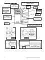
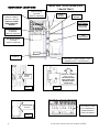
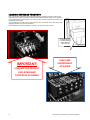
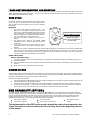
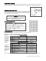
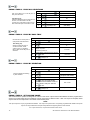
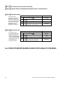
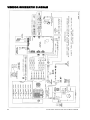
COMBO VENDOR MODEL 3548 SERVICE MANUAL INTRODUCTION ................................2 SPECIFICATIONS ...............................3 VENDOR SET UP ...............................4 UNPACKING ...............................................................4 INSTALLATION ............................................................4 GROUNDING (EARTHING) & ELECTRICAL ....................4 COMPONENT LOCATIONS ...........................................5 REFRIGERATION OPERATION .............................7 THERMOSTAT SETTING........................................7 LOADING SNACK PRODUCTS ....................................8 SPIRAL AND TRAY ADJUSTMENT ................................8 SPIRAL TIMING...........................................................8 PRODUCT PUSHERS ...................................................8 LOADING BEVERAGE PRODUCTS ............................9 LOADING COIN MECHANISM .................................... 10 BILL VALIDATOR OPERATION (OPTIONAL) ............ 10 SALES MODE ...................................10 DISPLAY CREDIT - ELECTRONIC PRICING ................. 10 "USE EXACT CHANGE" LED OPERATION ........... 10 "MAKE ANOTHER SELECTION" LED OPERATION ............................................................. 11 VEND CYCLE ........................................................... 11 CHANGE RETURN .................................................... 11 DEX CAPABILITY (OPTION) ............. 11 BEVERAGE AREA OPERATION......... 12 SOLD OUT VEND SEQUENCE .................................... 12 SERVICE MODE ............................... 13 SERVICE MODE BUTTON.......................................... 13 KEYPAD OPERATION ............................................... 13 PROGRAMMING ....................................................... 13 PRESS 1 - TUBE FILL AND DISPENSE COINS MODES.............................................................................13 PRESS 2 - MOTOR COUNT MODE ...............................14 OPTIONS MENU ..............................................................14 PRESS 3 THEN 1 - FORCE VEND OPTION ..................14 PRESS 3 THEN 2 - BILL ESCROW OPTION .................14 PRESS 3 THEN 3 - MULTI VEND OPTION ....................15 PRESS 3 THEN 4 - FREE VEND OPTION .....................15 The Model and Serial numbers are needed for you to obtain quick service and parts information for your vendor. The numbers are given on the identification plate located on the back of the vendor. Write them into the spaces below for your records. PRESS 3 THEN 6 - OPTICS OPTION ........................... 15 PRESS 4 - VENDOR CONFIGURATION MENU ........... 16 PRESS 4 THEN 3 - VENDOR CONFIGURATION......... 16 PRESS 4 THEN 6 - VENDOR SPACE-TO-SALES........ 16 PRESS 5 - PRICING ...................................................... 16 PRESS 5 THEN 3 - PRICE ALL SELECTIONS ............. 17 PRESS 5 THEN 2 - PRICE BY ROW / TRAY ................ 17 PRESS 5 THEN 1 - PRICE BY SELECTION ................. 17 PRESS 5 THEN 4 - SET COUPON VALUE ................... 17 PRESS 5 THEN 5 - SET TOKEN VALUE ...................... 18 PRESS 6 - ACCOUNTING MODE.................................. 18 PRESS 7 (not applicable in this model) .......................... 20 PRESS 8 - TEST VEND SELECTION MODE ................ 20 PRESS 9 - TEST VEND ALL SELECTIONS MODE ...... 20 PRESS 0 - DIAGNOSTICS MODE ................................. 21 PREVENTATIVE MAINTENANCE...... 23 PARTS ORDERING PROCEDURE ...... 23 BEFORE CALLING FOR SERVICE ...... 23 VENDOR SCHEMATIC DIAGRAM .... 24 If you have questions concerning the information in the manual, replacement parts, or the operation of the vendor, note your machine’s Model and Serial Numbers before contacting: VendNet MODEL NUMBER: _______________ SERIAL NUMBER: _______________ 165 North 10th Street Waukee, Iowa 50263 - USA Parts: (888) 259-9965 Service: (800) 833-4411 Parts Fax: 515-987-4447 All Other: (888) 836-3638 E-Mail: [email protected] INTRODUCTION This manual contains instructions, service and installation guidelines for the Combo Vendor. The Combo Vendor is designed as a combination snack and beverage merchandiser. The vendor is capable of dispensing a wide variety of snacks and beverages. The Combo Vendor model is equipped with an electronic control system. All vending functions, pricing, and features are programmed through the controller. Changes can be made without any additional accessories or remote parts. Selections can be priced individually from $.05 to $99.95 in five cent increments (US currency). Accountability mode records Total Cash transactions and Total Vend cycles performed by the vendor. Information for individual selections, complete rows or total vendor can be compiled and used for inventory and ordering records. Control System malfunctions are recorded and displayed when the vendor is placed in Service Mode. Nonfunctioning motors or selections are indicated. Each selection has an individual motor. When one selection motor fails the other selections are unaffected and will continue working. The vending sequence is ―first-in, first-out‖ for each selection, eliminating the need for stock rotation to ensure product freshness. Read this manual thoroughly. Become familiar with the vendor’s components and features. The initial setup of a vendor is a very important step towards insuring that the equipment operates trouble-free. Carefully follow the instructions for the initial installation of the vendor to avoid service problems and minimize setup time. Access to the service area of this vendor should be permitted only to individuals having knowledge and practical experience in vendor setup and loading, especially in areas of safety and hygiene. 2 4217818.001 Combo Vendor Service Manual REV B SPECIFICATIONS DIMENSIONS Width Height Depth Weight / Shipping Weight 34.5 inches (876mm) 72 inches (1829mm) 29 5/8 inches (752) mm 551 lbs. (254kg) / 600 lbs. (272kg) 34.5 inches (876mm) 72 inches (1829mm) 29 5/8 inches (752) mm 551 lbs. (254kg) / 600 lbs. (272kg) Snack Window Size (tempered glass only) 21 3/4" X 25 1/4" X 1/8" Thick (552mm X 641mm X 3mm) 21 3/4" X 25 1/4" X 1/8" Thick (552mm X 641mm X 3mm) Live Display Window Size (tempered glass only) 9 1/4" X 23 3/4" X 1/8" Thick (235mm X 603mm X 3mm) N/A STANDARD SNACK TRAY CONFIGURATION (MAY VARY) See manual page Trays Total Selections Snack Selections Medium Snack Selections Candy Selections Standard Capacity (may vary) Page 5 3 21 6 6 9 225 Page 6 2 14 4 4 6 150 STANDARD BEVERAGE TRAY CONFIGURATION (MAY VARY) See manual page Live Display Selections Live Display Can Selections Can Capacity Live Display Bottle Selections Bottle Capacity Pre cool bottle can Total Beverage Capacity (may vary) Page 12 8 3 130 5 56 n/a 186 page12 5 3 130 2 28 16 Bottles 34 Cans 208 ELECTRICAL Voltage Cycle Amperage Transformer COINAGE (NOTE: MDB Version International Domestic 120 VAC 60 Hz 2.5A/300W 120 VAC to 24 VAC 240 VAC 50 Hz 1.25A/300W 240 VAC to 24 VAC DOLLAR BILL VALIDATOR AND/OR CARD READER IS OPTIONAL) Industry Standard MDB Coin Mechanisms, Bill Validators and Card Readers (OPTIONALLY EQUIPPED) VENDOR OPERATION Location Sound Level Recommended Operating Temperature 3 Suitable for indoor use only. This appliance is not suitable for installation in an area where a water jet could be used. Produces less than 70 dBA during normal operation. Between 32° and 100° F° (0° and 37.8° Celsius) 4217818.001 Combo Service Manual REV B VENDOR SET UP UNPACKING This vendor was thoroughly inspected before leaving the factory and the delivering carrier has accepted responsibility for this vendor. Note any damage or irregularities at the time of delivery and report them to the carrier. Request a written inspection report from the claims inspector to file any claim for damage. File the claim with the carrier (not the manufacturer) within 15 days after receipt of the vendor. Carefully remove the outside packing material being careful not to damage the vendor’s finish or exterior. Inspect the vendor for concealed shipping damage. Report any damage hidden by the shipping material directly to the delivering carrier on a Hidden Damage Report. NOTE: if the power supply cord is damaged, it must be replaced by the manufacturer, its service agent, or similarly qualified individual in order to avoid hazard. INSTALLATION Position the vendor in its place of operation. Make sure to level the vendor by placing a bubble level on the top of the machine and adjusting the vendor leg levelers. Position the vendor so the power cord easily reaches the power outlet or receptacle (DO NOT USE AN EXTENSION CORD). Check that the door will open fully without interference. NOTICE: VENDOR MUST BE LEVEL AND THERE MUST BE A MINIMUM OF 4" BETWEEN BACK OF VENDOR AND THE WALL FOR PROPER AIR FLOW Retrieve the vendor keys from the coin return cup. Open outer door and remove all internal packing material. GROUNDING (EARTHING) & ELECTRICAL Consult local, state, and federal codes and regulations before installing the vendor. Refer to the Safety Installation Guidelines document found in the service package shipped with your vendor. Before connecting the vendor, the integrity of the main electrical supply must be checked for correct polarity, presence of ground (earth) and correct voltage. These checks should be repeated at six-month intervals with the routine safety electrical testing of the vendor itself. If the receptacle is not properly grounded or polarized, contact a licensed electrician to correctly polarize and/or ground the receptacle to ensure safe operation. For proper operation of any equipment utilizing electronically controlled components, the equipment should be placed on an isolated, or dedicated, noise-free circuit properly polarized and grounded. Use of a surge suppressor is recommended for locations where electrical noise is present. After all set up has been completed turn on the Power Switch (see Component Locations diagram later in manual). 4 4217818.001 Combo Vendor Service Manual REV B COMPONENT LOCATIONS INSIDE VIEW - DOOR SHOWN OPEN 3 SNACK TRAYS SERVICE MODE BUTTON (SEE FIG. 3 BELOW) DOOR SWITCH POWER SWITCH BACK OF CABINET (SEE FIG. 1 BELOW) TURN OFF POWER WHEN SERVICING VENDOR CONTROL BOARD OPTIONAL DOLLAR BILL VALIDATOR COIN MECHANISM BEVERAGE DOOR LATCHES (SEE FIG. 2 BELOW) LIVE DISPLAY (SEE FIG. 4 BELOW) COIN BOX AIR INTAKE - UNDER CABINET - KEEP SCREEN CLEAN - CLEAN MONTHLY LIFT UP ON LATCHES AND PULL OUT POWER SWITCH BE SURE LATCHES ARE CLOSED TIGHT BEFORE CLOSING OUTER DOOR FIG. 2 FIG. 1 SERVICE MODE BUTTON FIG. 3 5 REMOVE SCREW AND LIFT UP ON DOOR TO LOAD PRODUCTS INTO LIVE DISPLAY RE-INSTALL SCREW TO HOLD DOOR AND PRODUCT IN PLACE FIG. 4 4217818.001 Combo Service Manual REV B COMPONENT LOCATIONS SERVICE MODE BUTTON (SEE FIG. 3 BELOW) POWER SWITCH BACK OF CABINET (SEE FIG. 1 BELOW) TURN OFF POWER WHEN SERVICING VENDOR INSIDE VIEW - DOOR SHOWN OPEN 2 SNACK TRAYS DOOR SWITCH CONTROL BOARD OPTIONAL DOLLAR BILL VALIDATOR LIVE DISPLAY / STORAGE (SEE FIG. 4 BELOW) COIN MECHANISM BEVERAGE DOOR LATCHES (SEE FIG. 2 BELOW) COIN BOX AIR INTAKE - UNDER CABINET - KEEP SCREEN CLEAN - CLEAN MONTHLY LIFT UP ON LATCHES AND PULL OUT POWER SWITCH BE SURE LATCHES ARE CLOSED TIGHT BEFORE CLOSING OUTER DOOR FIG. 1 SERVICE MODE BUTTON FIG. 2 LIFT DISPLAY DOOR PULL FORWARD TO STORE PRODUCT / LOAD LIVE DISPLAY FIG. 3 6 4217818.001 Combo Vendor Service Manual REV B REFRIGERATION OPERATION THERMOSTAT The Vendor's refrigeration system will operate trouble-free for many years and with highest efficiency with proper operation and maintenance. It is critical that the machine be positioned with a minimum of a 4" space between the back of the machine and the wall. Also, it is critical that the bottom screen and refrigeration compartment be kept clean. Clean/vacuum the screen under the cabinet monthly. CLEAN SCREEN UNDER CABINET MONTHLY NOTICE: THERE MUST BE A MINIMUM OF 4" BETWEEN BACK OF VENDOR AND THE WALL FOR PROPER AIR FLOW WARMER COLDER THERMOSTAT SETTING The Vendor's thermostat is set at the factory and should not need to be adjusted. If the beverage compartment is too cold or too warm make slight adjustments and allow the interior temperature to stabilize for a minimum of 24 hours prior to making any further adjustments. Rotating clockwise adjusts colder … counterclockwise adjusts the temperature warmer. NOTICE: DO NOT MAKE LARGE ADJUSTMENTS AWAY FROM FACTORY SETTING AS THIS MAY RESULT IN A FREEZE UP OF THE EVAPORATOR COIL AND/OR BEVERAGES. PROLONGED FREEZE UPS WILL CAUSE THE REFRIGERATION TO OVERHEAT AND MAY CAUSE PERMANENT DAMAGE TO THE SYSTEM. 7 4217818.001 Combo Service Manual REV B LOADING SNACK PRODUCTS Lift the tray up slightly and pull forward until the tray stops then tilt down for ease of loading. Load product from front to back making sure all items fit freely between the spirals. Do not attempt to force oversized products or packages into the spaces. Do not skip a space. Place the product on the bottom of the compartment on the spirals with the labels facing the front of the vendor for easy identification by the customer. To vend properly the product must be wider and taller than the diameter of the spiral being used. Undersized products may cause vend problems. SPIRAL AND TRAY ADJUSTMENT The shape, size and thickness of a product affect how well it falls off the tray. Most products can be vended successfully when the spiral end is positioned at 6 o’clock. If vending problems occur with spiral ends at the standard 6 o’clock position, adjust the drop-off either by retiming the spiral or installing a Product Pusher. ADJUST SPIRAL COUNTER CLOCKWISE FOR THICKER PRODUCTS SPIRAL TIMING Each spiral can be rotated in 45º (degree) increments for a different drop-off point. Most products can be vended successfully when the spiral end is positioned at the position of 6 o’clock. ADJUST SPIRAL CLOCKWISE FOR THINNER PRODUCTS (i.e. 7:00 (0'CLOCK)) (i.e. 3:00 (0'CLOCK)) The general rule is: The narrower the product, the higher the timing. Thick Products - 4-6 o’clock Most products – 6 o’clock Thin Products - 6-8 o’clock ADJUST SPIRAL END POSITION FOR SUCCESFUL VEND. MOST PRODUCTS VEND PROPERLY AT THE 6:00 (0'CLOCK) SETTING SHOWN ABOVE To change the spiral end position: 1. 2. 3. 4. 5. Remove the tray to have access to the back of the motors. Pinch the snap tabs of the spiral coupling and push out until it separates from the motor. Rotate the spiral to the desired position and reinsert the spiral coupling into the motor. Make sure the spiral coupling snaps fully into the motor as shown. Replace the tray and test vend the selection to make sure product vends correctly. ADJUST SPIRAL END POSITION BY PINCHING SNAP TABS OF SPIRAL COUPLING ON BACK OF MOTOR - PULL OUT OF MOTOR THEN SNAP BACK INTO DESIRED POSITION PRODUCT PUSHERS If the product still will not vend properly after re-timing of the spiral then install a Product Pusher. The Product Pushers are provided in the service package of the vendor. Snap onto spirals only as necessary as shown. IF AFTER ADJUSTING THE SPIRAL END THE PRODUCT STILL DOESN'T FALL OFF TRAY … SNAP PROVIDED PRODUCT PUSHERS ONTO END OF SPIRALS TO ENSURE PRODUCT WILL FALL 8 4217818.001 Combo Vendor Service Manual REV B LOADING BEVERAGE PRODUCTS Push in on latches simultaneously on both sides of trays then pull forward until the tray stops to load. Load product from front to back making sure all items fit freely between the spirals. Do not attempt to force oversized products into the spaces. Do not skip a space. Place the product on the bottom of the compartment on the spirals. To vend properly the product must be wider and taller than the diameter of the spiral being used. Undersized products may cause vend problems. Load bottle product cap down in bottle trays as shown. Can tray is for 12oz. cans only. PUSH IN ON TRAY LATCHES ON BOTH SIDES AND PULL OUT TO LOAD IMPORTANT: LOAD BOTTLED PRODUCT CAPS DOWN AND TILTED BACK AS SHOWN 9 LOAD CANS HORIZONTALLY AS SHOWN 4217818.001 Combo Service Manual REV B LOADING COIN MECHANISM The Coin Mechanism must be loaded with some level of each coin in order for the vendor to operate properly. The coins need to be loaded into the coin mechanism by insertion into the front coin insert. PRESS SERVICE MODE BUTTON AND ENTER TUBE FILL MODE (PRESS 1) First enter the SERVICE MODE then TUBE FILL MODE (See SERVICE MODE instructions, pg.8). Make sure to load the correct coins into their correct tubes. Each tube should be kept loaded with at least one roll of each coin to keep above the tube low level sensors. Once the tubes are loaded to these levels the Dollar Bill INSERT COINS THROUGH FRONT DOOR COIN INSERT TO FILL COIN TUBES Validator will accept bills. If the coin tubes fall below this level the Dollar Bill Validator may stop accepting bills and the front display will light the "EXACT CHANGE ONLY" indicator LED. Alternatively, you can load the coins into the slots above the respective coin tubes. This is not the preferred method. By using TUBE FILL mode the control board can then accurately determine coin levels. On some Coin Mechanisms there are buttons above each tube to dispense the coins (may vary depending on which coin mechanism that is used). The coins can also be dispensed within the Service Mode described later. More advanced and brand specific Coin Mechanism operating instructions can be obtained on the Service portion of the website listed at the beginning and end of this manual BILL VALIDATOR OPERATION (OPTIONAL) To remove the bills from the Dollar Bill Validator push the tab on the top of the bill box and lift up. To clear jams or cleaning unlatch lower unit as shown. Dollar Bill Validator cleaning instructions as well as more advanced service information can be obtained on the Service portion of the website listed at the beginning and end of this manual. SALES MODE The vendor automatically defaults to Sales Mode after it is turned on. In the Sales Mode, the vendor accepts money deposits, pays out change and dispenses product to the customer. DISPLAY CREDIT - ELECTRONIC PRICING This vendor is equipped with the Electronic Pricing feature. The customer verifies the price by pressing the selection number (i.e. 22) before inserting money. If a selection is made and credit has not been established, the price for that selection is displayed and will flash. When money or credit is accepted, then the amount of credit is displayed. "USE EXACT CHANGE" LED OPERATION If the coin levels in the coin mechanism tubes are below the low-level sensors, the indicator LED next to ―USE EXACT CHANGE‖ will illuminate. This indicates the Coin Mechanism does not have enough coins in the coin mech tubes to make change. This also indicates that the Dollar Bill Validator may be disabled until change can be made. 10 4217818.001 Combo Vendor Service Manual REV B "MAKE ANOTHER SELECTION" LED OPERATION If a selection is made that is not available (i.e. 79 is not a good selection) or if there is a selection motor failure the indicator LED next to ―MAKE ANOTHER SELECTION‖ will illuminate. If this is a motor failure the controller will display which motor has failed upon entering the Service Mode (described later in this manual). VEND CYCLE If a selection is made and the accumulated credit is greater than or equal to the price of the selection, then a vend attempt will take place. If credit is less than the selection price, the price is displayed and will flash. Operation 1. 2. 3. 4. 5. The control system verifies the selection exists. If the selection is not available or failed previously the cycle stops and the "MAKE ANOTHER SELECTION" indicator LED is illuminated. The control system stores this error MOTOR HOME POSITION that will be displayed in the SERVICE MODE of operation. BACK OF MOTOR SHOWN If no error is detected the vend cycle continues. The vend motor starts its rotation and a vend timer is … MOTOR ROTATES started. UNTIL SWITCH OPENS ON The selection motor rotates to the MOTOR HOME FLAT OF CAM POSITION (as shown). The motor switch opens on the flat of motor cam. If the home switch signal is sensed, then the vend is considered successful. The amount of remaining credit is returned. If there is no home switch signal detected and the vend timer has expired (approx. 10 seconds), then the vend is considered failed. The vend motor is then shut down and ―MAKE ANOTHER SELECTION‖ indicator light is turned on. The customer can press selection buttons to make another selection or they can press the coin return button to receive their money back. A failed motor must be test vended in the Service Mode to clear the failure. Credit and Counters After a successful vend … The total non-resettable vend count is incremented by one and the total non-resettable cash value is incremented by the price of the vended selection. The total resettable vend count is incremented by one and the resettable total cash value is incremented by the price of the vended selection. NOTE: Test vends are not included in the counter totals. CHANGE RETURN If after inserting credit the customer desires their money back the coin return button needs to be pressed. Upon insertion of a dollar bill and a change request is desired the vendor will do one of two things depending upon the setting of the FORCE VEND and BILL ESCROW features (operation as described later in the Service Mode section of this manual). Two modes of change return operation … If the bill is inserted and FORCE VEND is set to OFF and BILL ESCROW is set to ON when the customer requests change they will receive their bill back from the Dollar Bill Validator. If the bill is inserted and FORCE VEND is set to OFF and BILL ECROW is set to OFF when the customer requests change they will receive coin change back … the vendor can be used as a bill changer. Operating the vendor in this manner is fine except the vendor may run low on coins more often and thus not be able to accept bills and may result in lost sales. DEX CAPABILITY (OPTION) This vendor has the option of DEX capability. DEX is an acronym for Direct EXchange. It is a vending industry communication standard which was originally created for the grocery industry. The option permits the operator to download with a handheld computer accounting data from the control board automatically. This data can then be used to accurately track cash accountability as well as evaluate the product marketing aspects within one vendor or many. The DEX option requires the purchase of extra harnessing, a handheld computer, and software to be used effectively. The data set which is defined includes, among others: Cash Count by selection Prices by selection Value of Bills in the bill validator Vend Count by selection Value of Coin in the Coin box The implementation of the DEX option may be beyond the needs of most operators but if more information is desired contact the service entity listed at the beginning and end of this manual 11 4217818.001 Combo Service Manual REV B BEVERAGE AREA OPERATION The Beverage Area motors are combined in a preset fixed pattern corresponding to the visible Live Display selections. Notice that Selection 40 is actually tied to two motors in the Top Can Tray … Selection 42 is tied to the next two motors … Selection 44 is tied to the fifth motor in that tray. In the same manner, Selection 50 is tied to the first four motors in the Middle Bottle Tray … Selection 54 is then tied to motors 5-7 on that tray and so on. THE SELECTIONS INSIDE THE MACHINE ARE LINKED TO THE 8 OR 5 DISPLAYED SELECTIONS IN THE OUTER DOOR DISPLAY … AS SHOWN BELOW The Control System will rotate through the tied motors within a selection. For example: when a customer selects Selection 50 the Control System will remember which motor was last vended and vend the next motor in that sequence. By vending in sequence this ensures a first-in / first-out rotation of product. This combining of motor columns (Space-to-Sales) in varying quantities creates different capacities for each Selection. This combining of motors to selections is fixed and provides the following capacities by Selection: selection 1 can tray 1 can tray 2 bottle trays 1 bottle tray 40 52 (12oz. Cans) 52 (12oz. Cans) Total 42 52 (12oz. Cans) 52 (12oz. Cans) 44 26 (12oz. Cans) 26 (12oz. Cans) 12 oz. Can Capacity = 50 16 (24 oz. max.) 16 (24 oz. max.) TOP TRAY - 12 oz. CANS ONLY Selection Selection Sel 40 42 44 Totals 1 Pre cool tray 54 12 (24 oz. max.) 12 (24 oz. max.) 60 12 (20 oz. max.) PRE COOL 63 8 (20 oz. max.) 16 BOTTLES 65 8 (20 oz. max.) OR 34 CANS Total 186 208 MIDDLE TRAY - CANS OR BOTTLES (up to 24 oz.) Total Bottle (or Cans) Capacity = SOLD OUT VEND SEQUENCE If a selection is made and the accumulated credit is greater than or equal to the price of the selection, then a vend attempt will take place. If credit is less than the selection price, the price is displayed and will flash. Selection 50 Selection 54 OPTION PRE COOL BOTTOM TRAY - CANS OR BOTTLES (up to 20 oz.) Selection 60 The beverage area is equipped with a Vend Sensing system. Selection Selection 63 65 Upon selection of a beverage selection the control system determines whether there is product available to vend. When a vend request is made the Control System monitors whether a beverage product impacts the SOLDOUT SENSOR BRACKET. The SOLDOUT SENSING BRACKET is attached to a switch that opens when an impact occurs. This is a successful vend attempt and the normal vend cycle follows. If the Control System does not sense an impact to the SOLDOUT SENSING BRACKET then the Control System will attempt to rotate that selection motor one additional time. If a product impact is sensed at this time then this is considered a successful vend and the normal vend cycle follows. If upon this second attempt no product impact is sensed then that motor is flagged as SOLD OUT. The Control System will then attempt to vend the next motor tied to that selection using the same two-rotation process. If a product impact is not sensed it then moves on to the next motor tied to that selection. It will continue this process until it has attempted a two-rotation process for each motor tied to that selection. If all attempts fail then the entire selection will be flagged as SOLD OUT and the "MAKE ANOTHER SELECTION" indicator LED is illuminated. The Control System will not attempt to vend any motor after is it flagged as SOLD OUT until the motors are reset to not SOLD OUT. The Control System will monitor the DOOR SWITCH Door Switch located on the inside of the main outer door. Once the main outer door is opened the switch will open and the Control (INSIDE DOOR) System will assume all beverages have been loaded and reset SOLDOUT the flagged motors to active (not SOLD OUT). SENSOR Vend and Cash counters only will increment on successfully vended product. If BRACKET the customer fails to receive their beverage they have the option of vending another product or receiving their money back (change). 12 4217818.001 Combo Vendor Service Manual REV B SERVICE MODE The Service Mode is used to access the programming features of the controller: Set Price, Test Vend, Retrieve Accounting Information, or Set Custom Program Settings. If credit exists when entering the Service Mode, it will be restored when the vendor is returned to Sales Mode. SERVICE MODE BUTTON SERVICE MODE BUTTON The Service Mode Button is located near the top right corner of the control board. Press the button to access the Service Mode programming features. Press the button again to exit and return to Sales Mode. If no keypad button is pressed within 60 seconds while in Service Mode, the controller automatically exits to the Sales Mode. DISPLAY Check the display after pressing the Service Mode Button and/or Keypad Buttons to make sure that the program is responding correctly. KEYPAD OPERATION In Service Mode buttons thru are used to access the various modes, menus and sub-menus as well as entering price values The asterisk/star button is used to escape or back up within menus. Pressing the asterisk/star button repeatedly will back out of the Service Mode into the Sales Mode of operation. The pound/number symbol or save a setting. button is used to enter a menu, confirm PROGRAMMING Press the Service Mode Button; check the display for instructions or choices while using the keypad. PRESS 1 - TUBE FILL AND DISPENSE COINS MODES Tube Fill Mode counts coins as they are deposited and shows the deposited amount. This permits the control system to accurately track coin tub e inventories Dispense Coins Mode pays out coins from the coin mech coin tubes. This mode will also display the current quantity of coins in the coin mech tubes. TUBE FILL MODE STEP 1. Press Service Mode Button 2. Press and begin depositing coins Press repeatedly to exit. 3. DISPLAY 40 (Motor Count is displayed) Totalized amount of entered coins (Sales Mode) DISPENSE COINS MODE STEP DISPLAY 1. Press Service Mode Button 2. Press 3. Then Press 4. Or Press to dispense dimes .10 - (10¢ coins) 5. Or Press to dispense nickels .05 - (5¢ coins) 6. Or Press 7. Press to enter coin mode to dispense quarters to dispense more than 3 coin types repeatedly to exit. 40 (Motor Count is displayed) .25 .25 - (25¢ coins) See Note below (Sales Mode) **Note: For dispensing of coins on coin mechanisms with more than 3 tubes use keys greater in the same sequence as shown above.** 13 4217818.001 Combo Service Manual REV B PRESS 2 - MOTOR COUNT MODE STEP Motor Count Mode displays the total quantity of working motors. DISPLAY 1. Press Service Mode Button 40 (Motor Count is displayed) 2. Press then wait … counts available motors 40 (Motor Count is displayed) Press to exit. 3. (Sales Mode) OPTIONS MENU This menu allows access to the following features: FORCE VEND OPTIC OPTION BILL ESCROW POS MESSAGE (not applicable in this model) MULTI VEND TEMPERATURE (not applicable in this model) FREE VEND KEYPAD BACKLIGHT (not applicable in this model) FAST CHANGE (not applicable in this model) DROP SENSOR SENSITIVITY (not applicable in this model) and PRESS 3 THEN 1 - FORCE VEND OPTION By pressing then this alternates between FORCE VEND ON (displayed as FrcY) or FORCE VEND OFF (displayed as Frcn). STEP This option will force the customer to complete a purchase once they have deposited money of any form. 1. Press Service Mode Button 2. Press OPtn 3. then Press 4. Press to save setting. Press repeatedly to exit. 3. DISPLAY 40 (Motor Count is displayed) … repeat to toggle mode ON/OFF FrcY or Frcn (default is FrcN) FrcY or Frcn (last displayed setting) (Sales Mode) and PRESS 3 THEN 2 - BILL ESCROW OPTION By pressing then this alternates between BILL ESCROW ON (displayed as ESCY) or BILL ESCROW OFF (displayed as ESCn). STEP This option allows the last bill accepted to be returned, provided the bill acceptor is capable of such a feature. 1. Press Service Mode Button 2. Press 3. then Press 4. Press to save setting. Press repeatedly to exit. 3. DISPLAY 40 (Motor Count is displayed) OPtn … repeat to toggle mode ON/OFF ESCY or ESCn (default is ESCY) ESCY or ESCn (last displayed setting) (Sales Mode) NOTE: If you want the vendor to be used as a dollar bill changer (customer inserts bill then presses the asterisk/star button to receive coin change for bill) then set FORCE VEND to OFF (Frcn) and BILL ESCROW to OFF (ESCn). Operating the vendor in this manner is fine except the vendor may run low on coins more often and thus not be able to accept bills and may result in lost sales. 14 4217818.001 Combo Vendor Service Manual REV B AND PRESS 3 THEN 3 - MULTI VEND OPTION By pressing then this alternates between MULTI VEND ON (displayed as NULY) or MULTI VEND OFF (displayed as NULn). STEP This option allows the customer to purchase more than one product if enough credit has been deposited. When this option is active, any credit remaining after a vend attempt is not automatically returned. At this point, the customer has the option of: DISPLAY 1. Press Service Mode Button 2. Press 3. then Press Making another selection if there's enough credit OR Depositing more money OR 4. Press to save setting. Press the asterisk/star remaining credit. 3. Press repeatedly to exit. button to receive 40 (Motor Count is displayed) OPtn … repeat to toggle mode ON/OFF NULY or NULn (default is NULn) NULY or NULn (last displayed setting) (Sales Mode) NOTE: After 5 minutes any credit that is left on the display will disappear AND PRESS 3 THEN 4 - FREE VEND OPTION By pressing then This option makes all products available at no cost. No money is accepted by the vendor. The message "FREE" is displayed. This does not change the set prices. Once FREE VEND is set to OFF the selection prices revert back to the price set amounts. this alternates between FREE VEND ON (displayed as FrEY) or FREE VEND OFF (displayed as FrEn). STEP 1. Press Service Mode Button 2. Press 3. then Press 4. Press to save setting. Press repeatedly to exit. 3. DISPLAY 40 (Motor Count is displayed) OPtn … repeat to toggle mode ON/OFF FrEY or FrEn (default is FrEn) FrEY or FrEn (last displayed setting) (Sales Mode) AND PRESS 3 THEN 6 - OPTICS OPTION By pressing then This option must be set to oPtY for this model. This along with the Space-to-Sales setting turns on the vend sensor for the beverage selections. There is no vend sensor for the snack selections. this alternates between OPTICS ON (displayed as oPtY) or OPTICS OFF (displayed as oPtn). STEP 1. Press Service Mode Button 2. Press 3. then Press 4. Press to save setting. Press repeatedly to exit. 3. DISPLAY 40 (Motor Count is displayed) OPtn … repeat to toggle mode ON/OFF oPtY or oPtn (Must be set to oPtY) Make sure displays oPtY (Sales Mode) AND , AS WELL AS AND THRU ( ALL OTHER OPTIONS) WITHIN (MODE 3) ARE NOT APPLICABLE TO THIS MODEL 15 4217818.001 Combo Service Manual REV B PRESS 4 - VENDOR CONFIGURATION MENU This menu allows access to the following features: ITEM (can/bottle) - (not applicable in this model) ROW (snack/can/bottle) - (not applicable in this model) SPACE-TO-SALES (STS) ADVANCED CONFIGURATION - (not applicable in this model) ALL (snack/can/bottle) NOTE: This model requires that the entire vendor be set to SNACK … to reset this back to factory setting: AND - PRESS 4 THEN 3 - VENDOR CONFIGURATION By pressing then This sets the operating mode of the vendor. This model should always be set to a SNACK configuration (SnAc). repeatedly this sets vendor configuration … must be set on SnAc STEP 1. Press Service Mode Button 2. Press 3. then Press 4. Press to save setting. Press repeatedly to exit. 3. AND DISPLAY 40 (Motor Count is displayed) Cbs ALL … SnAc until displays SnAc Make sure displays SnAc (Sales Mode) - PRESS 4 THEN 6 - VENDOR SPACE-TO-SALES By pressing then This sets the Space-to-Sales mode of the vendor. This model should always be set to a STSF configuration. repeatedly this sets vendor space-to-sales … must be set on STSF STEP 1. Press Service Mode Button 2. Press 3. then Press 4. Press to save setting. Press repeatedly to exit. 3. DISPLAY 40 (Motor Count is displayed) Cbs until displays STSF STSF Make sure displays STSF (Sales Mode) PRESS 5 - PRICING (The maximum price that can be set is $99.95) ITEM — set price by individual selections ROW— set price by tray ALL ITEMS — set price by entire vendor. COUPONS — set coupon value by Item, Row, or ALL TOKENS — set token value by Item, Row, or ALL 16 4217818.001 Combo Vendor Service Manual REV B AND - PRESS 5 THEN 3 - PRICE ALL SELECTIONS STEP DISPLAY This menu allows you to set the price of every item all at once. 1. Press Service Mode Button 2. Press Prc Time Saving Tip: Instead of setting the price of each item one at a time, it is much faster to set the common price of the entire vendor; then go back and set the price of each item or row. 3. Press Enter price (i.e. 50 = .50) ALL AND 4. 4. 5. Press to save. Press repeatedly to exit. 40 (Motor Count is displayed) 0.50 0.50 (Sales Mode) - PRESS 5 THEN 2 - PRICE BY ROW / TRAY STEP Use this menu to set the price of a tray/row all at the same time. Time Saving Tip: Instead of setting the price of one item at a time, set the common price of a Tray/Row, then go back and set the price of each item. Press Service Mode Button 2. Press Prc 3. Press Enter tray/row number and price Example: Top row=1, row below top row=2, etc. Program will then request input of the next Row. ro - 4. 5. 6. AND DISPLAY 1. Press to save. Press repeatedly to exit. 40 (Motor Count is displayed) ro 01 0.50 ro 01 0.50 (Sales Mode) - PRESS 5 THEN 1 - PRICE BY SELECTION STEP This menu allows price setting by each selection . Press Service Mode Button 2. Press Prc 3. Press 4. Enter selection and price -(prompted to enter selection) 10 0.50 5. 6. AND DISPLAY 1. 40 (Motor Count is displayed) Press to save. The program will then request input of the next selection number and you can continue to enter prices. Each time Press to save. Press repeatedly to exit. Item 11 0.50 (Sales Mode) - PRESS 5 THEN 4 - SET COUPON VALUE This mode allows the operator to designate the values of "free vend" coupons that the bill validator has been programmed to accept. The control board can have 5 different coupons each having a different value. After one coupon is accepted, further coupons will not be accepted until a successful vend has taken place. NOTE: This option requires a coupon programmed bill validator. The coupons are special order. The specially programmed bill validator and special coupons can be purchased from the parts entity listed at the beginning and end of this manual. If no coupon value is set, coupons will be shown as free vends. 17 4217818.001 Combo Service Manual REV B STEP DISPLAY 1. Press Service Mode Button 2. Press Prc 3. Press CPn 4. Press 5. Enter desired Coupon1 Value … setting to 0.00 will set Coupon Value one Free Vend 1.50 6. Press 1.50 7. Press 2 times to add values for Coupons 2-5 or Press to Sales Mode. AND 40 (Motor Count is displayed) CPn1 0.00 for Coupon 1… the set value is shown to save. repeatedly to exit - PRESS 5 THEN 5 - SET TOKEN VALUE This mode allows the operator to designate the values of "free vend" tokens.. The control board can have 5 different tokens each having a different value. NOTE: This option requires a specially tuned coin mechanism. The tokens are special order. The specially tuned coin mechanism and special tokens can be purchased from the parts entity listed at the beginning and end of this manual. If no token value is set, tokens will be shown as free vends. STEP DISPLAY 1. 40 (Motor Count is displayed) Press Service Mode Button 2. Press Prc 3. Press thn 4. Press 5. Enter desired Token1 Value … setting to 0.00 will set Token Value one Free Vend 1.50 6. Press 1.50 7. Press 2 times to add values for Tokens 2-5 or Press Sales Mode. thn1 0.00 for Token 1 … the set value is shown to save. repeatedly to exit to PRESS 6 - ACCOUNTING MODE This mode accesses the submenus that displays or resets data for various types of cash and vend totals. Counts can be viewed by individual items, rows or as the whole vendor. The counter s rollover at 999,999 vends and $999,9999.99 sales. Historical Totals: These are the counts since the initialization of the vendor. They cannot be reset. Resettable Totals: These are totals since the last reset. These can be reset at any time. You have the option to reset just an item, row or the whole vendor. Note: Clearing counts only clears the resettable counters. Clearing by item and row will only clear the item or row entered. 18 4217818.001 Combo Vendor Service Manual REV B Description of counters: Historical Vend Count: Total number of vends ever Historical Cash Count: Total cash value ever sold Resettable Vend Count: Total number of vends since counters were last reset/cleared Resettable Cash Count: Total cash value since counters were last reset/cleared AND - ACCOUNTING TOTALS FOR ALL SELECTIONS - ENTIRE VENDOR This menu displays the total sales values and total vend count for the entire vendor. STEP DISPLAY 1. Press Service Mode Button 2. Press 3. Press 4. Press - Historical Vend Count 28 (example) 5. Press - Historical Cash Count 21.00 (example) 6. Press - Resettable Vend Count 14 (example) 7. Press - Resettable Cash Count 10.50 (example) 12. Press to clear counters for all selections then Clr? 13. Press again to confirm clearing of counters for all selections Clrd Press repeatedly to exit to Sales Mode. 14. AND 40 (Motor Count is displayed) Acct then press … All … 28 (example) (Sales Mode) - ACCOUNTING TOTALS FOR A ROW/TRAY This menu displays the total sales values and total vend count for a row/tray in the vendor. STEP Press Service Mode Button 2. Press 3. Press then enter row/tray number 4. Press - Historical Vend Count 14 (example) 5. Press - Historical Cash Count 10.50 (example) 6. Press - Resettable Vend Count 7 (example) 7. Press - Resettable Cash Count 5.25 (example) 12. Press to clear counters for all selections then Clr? 13. Press again to confirm clearing of counters for all selections Clrd Press repeatedly to exit to Sales Mode. 14. 19 DISPLAY 1. then press … 40 (Motor Count is displayed) Acct ro 1 … 14 (example) (Sales Mode) 4217818.001 Combo Service Manual REV B AND - ACCOUNTING TOTALS FOR A SELECTION This menu displays the total sales value and total vend count for an individual selection. STEP DISPLAY 1. Press Service Mode Button 2. Press then press … 3. Press then enter selection number (i.e. 22) 4. Press - Historical Vend Count 10 (example) 5. Press - Historical Cash Count 8.50 (example) 6. Press - Resettable Vend Count 4 (example) 7. Press - Resettable Cash Count 3.00 (example) 12. Press to clear counters for all selections then Clr? 13. Press again to confirm clearing of counters for all selections Clrd Press repeatedly to exit to Sales Mode. 14. 40 (Motor Count is displayed) Acct - - … 22 (example) (Sales Mode) PRESS 7 (NOT APPLICABLE IN THIS MODEL) PRESS 8 - TEST VEND SELECTION MODE Use this menu to test vend individual selection motors. The selection will display during the test vend. If a test vend fails the indicator LED next to the "MAKE ANOTHER SELECTION" will illuminate. STEP NOTE: Test vends are not included in the ACCOUNTING MODE counter totals. DISPLAY 1. Press Service Mode Button 40 (Motor Count is displayed) 2. Press 3. Press selection number on keypad and wait 4. Repeat step 3 for other selections. 5. Press repeatedly to exit to Sales Mode. -10 (Sales Mode) PRESS 9 - TEST VEND ALL SELECTIONS MODE This menu will test vend all selection motors. Each selection will display as it vends. If a test vend attempt on a particular motor fails, then the indicator LED next to the "MAKE ANOTHER SELECTION" will illuminate. NOTE: By entering this mode each selection motor will turn … any product loaded will be vended … if the door is open, be prepared to catch product as it is vended. STEP NOTE: Pressing at any time will stop the test. If a selection motor does not stop at home test that individual selection to return it to the home position 1. Press Service Mode Button 2. Press and wait. The motor selection number will display while it is being tested. 3. 4. 20 DISPLAY 40 (Motor Count is displayed) 10 40 Press to stop the test Press repeatedly to exit to Sales Mode. (Sales Mode) 4217818.001 Combo Vendor Service Manual REV B PRESS 0 - DIAGNOSTICS MODE AND - VENDOR SELF-DIAGNOSTIC TEST STEP This menu is used to perform a vendor selfdiagnostics test. Monitor the display for possible error messages. Record errors as they are displayed. DISPLAY 1. Press Service Mode Button 40 (Motor Count is displayed) dIAG Press 2. Press tESt (test start) E## (failed motor(s)) CtL (control board test) ChSu (check sum control board test) Cn (Coin Mechanism test) biLL (bill validator test - (when installed - option) rdr1 (card reader test - (when installed - option) to start test repeatedly to exit to 3. Press Sales Mode. (Sales Mode) Possible Error Codes Displayed Error Description E## or ESc oPEn (displayed when entering Service Mode) Selection Motor Diagnostic ## = motor that has failed or Possible Remedy Check motor connection, test vend motor ESc oPEn - Coin Return Motor failed Control Board input Error Good or Sl (keypad stuck) Keypad stuck error: check keypad connection, test all buttons, replace keypad ChSu Control board checksum error Good or Fail Upon Fail turn power off … wait 30 seconds and turn power back on … continues to Fail - replace control board Cn Coin Mechanism Diagnostic Good or Chg3 (communication error) turn power off … check coin mechanism connection … wait 30 seconds and turn power back on … continues to display Chg3 - replace coin mechanism biLL (when installed option) Bill Validator Diagnostic Good or Bil7 (communication error) turn power off … check bill validator connection … wait 30 seconds and turn power back on … continues to display Bil7 - replace bill validator rdr1 (when installed option) Card Reader Diagnostic Good or rdr8 (communication error) turn power off … check card reader connection … wait 30 seconds and turn power back on … continues to display rdr8 - replace card reader Ctl For additional trouble shooting assistance contact the service entity listed at the beginning and end of this manual. 21 4217818.001 Combo Service Manual REV B AND - TEST RELAY (NOT APPLICABLE IN THIS MODEL) AND - CONTROL BOARD LOG (ENGINEERING DIAGNOSTIC MENU - TECHNICIAN ONLY!) AND - COIN REJECT RATE STEP This mode tracks the percentage of coins that have been rejected by the coin mechanism. This will be reset when ALL counters are reset in the ACCOUNTING MODE. A high reading (> 10%) may indicate an unclean or damaged coin mechanism. AND DISPLAY 1. Press Service Mode Button 2. Press 3. Press to view reject percentage Press repeatedly to exit to Sales Mode. 4. 40 (Motor Count is displayed) Diag CrJ (Sales Mode) - BILL REJECT RATE STEP This mode tracks the percentage of bills that have been rejected by the bill validator. This will be reset when ALL counters are reset in the ACCOUNTING MODE. A high reading (> 15%) may indicate an unclean or damaged bill validator. DISPLAY 1. Press Service Mode Button 2. Press 3. Press to view reject percentage Press repeatedly to exit to Sales Mode. 4. 40 (Motor Count is displayed) Diag brJ (Sales Mode) ALL OTHER OPTIONS WITHIN (MODE 0) ARE NOT APPLICABLE TO THIS MODEL 22 4217818.001 Combo Vendor Service Manual REV B PREVENTATIVE MAINTENANCE CAUTION: ALWAYS DISCONNECT POWER SOURCE BEFORE CLEANING OR SERVICING WARNING: THIS VENDOR MUST NOT BE CLEANED WITH A WATER JET. ONCE A MONTH Clean Screen under cabinet Keep refrigeration compartment free of dust, lint, and debris Clean cabinet interior Wash with a mild detergent and water, rinse and dry thoroughly. Odors may be eliminated by including baking soda or ammonia in the cleaning solution. Plastic parts may be cleaned with a quality plastic cleaner. The vend mechanism must be kept clean. Any build-up can cause the mechanisms to malfunction. Do not get the cleaning solution on electrical components. To insure proper vending keep delivery slide area free of dirt and sticky substances. Clean Cabinet Exterior Wash with a mild detergent and water, rinse and dry thoroughly. Clean occasionally with a quality car wax or cleaner. PARTS ORDERING PROCEDURE When ordering parts, include the following: Model and serial number of the vendor Shipping address Address where the invoice should be sent Quantity of parts ordered Any special shipping instructions Desired carrier: air or air special, truck, parcel post, or rail. Signature and ordering date. If a purchase order is used, be sure is it visible and legible Please be sure that you refer to the correct part number, vendor model number, and vendor serial number when ordering. These can be confirmed by checking the parts manual found. Further information can be obtained on the Service portion of the website listed at the beginning and end of this manual. NOTE: ―Left‖ or ―Right‖ when used in the name or description of the part are determined while facing the front of the vending vendor with the door closed. BEFORE CALLING FOR SERVICE Please check the following: If the power is turned on at the fuse box, is the vendor the only thing that does not work? Is the vendor plugged directly into the outlet? Is the circuit breaker at the fuse box reset? WARNING: Do not use extension cords! NOTE: Please have your Model and Serial Number available when you call. 23 4217818.001 Combo Service Manual REV B VENDOR SCHEMATIC DIAGRAM 24 4217818.001 Combo Vendor Service Manual REV B NOTES: If you have questions concerning the information in the manual, replacement parts, or the operation of the vendor, note your machine’s Model and Serial Numbers before contacting: VendNet 165 North 10th Street Waukee, Iowa 50263 - USA Parts: (888) 259-9965 Service: (800) 833-4411 Parts Fax: 515-987-4447 All Other: (888) 836-3638 E-Mail: [email protected] 25 4217818.001 Combo Service Manual REV B