1
----SHARP----
SERVICE MANUAL
CE-150
Color graphic printer
WWW.
PC-1500
.INl'O
SHARP CORPORATION
Do not sale this PDF !!!
All and more about Sharp PC-1 500 at http://www.PC-1500.info
SERVICE MANUAL
DPG 1301
COLOR GRAPHIC PRINTER
{CE-150 Printer)
TABLE OF CONTENTS
Page
I. FEATURES AND OUTLINE . . . . . . . . . . . . . . . . . . . . . . . . . . . . . . . . . .
2. SPECIFICATIONS , • , • , •.• , , .•.•.•.•• . . .. • . .. • , ......... .. . .
3. MECHANISM A.ND OPERATION . . . . . . . • . . . . . . . . . . . . . . . . . . . . . . .
4. DISASSEMBLY AND REASSEMBLY . . . . . . . . . . . . . . . . . . . . . . . . . . . .
S. REPAIR AND MAINTENANCE . . . . . . . . . . . . . . . . . . . . . . . . . . • . . . . .
6. OILING STANDARD . . . . ....... . . . . .. . . .. . . . .. . .. . . . . . . . . . . .
7. ADHESION STANDARD . ... . . . ... . . . ... . .. . ....... . . . . ... . ..
8. CIRCUIT DIAGRAM & WIRING . . ... . .. .. . . . . . . . . ... . .. . • . . . . .
9. PARTS GUrnE AND PARTS LIST .... . ....... . . . • . . . • .. . . . ....
File this manual into the service manual "PC-1500 & Option"
Do not sale this PDF !! !
I
4
8
16
26
27
28
29
All and more about Sharp PC-1500 at http:/lwww.PC-1500.info
Tho Color Graphic P"rinter DPG 1301 is an X·Y polottcr that uses ball·point pens as it s writing instru·
ments. Driven by stepping motors, it is capable of high accuracy plotting with a resolution of 0.2 mm
and printing at a speed of 12 cps. The carriage bas a four-pen capacity. COior selection is done by
moving the caniagc in an X axial direction, permitting random color graphic plotting. The printer has
tl1c folowing features:
I) 4-color graphic plotting
2) Compactness and light weight
3) High resolution of 0.2 mm x 216 steps
4) Printing of a max.imum of 36 columns/line
5) Powered by a nickel-cadmium battery
6) 58 nun width plain paper can be used
Do not sale this PDF !!!
All and more about Sharp PC-1500 at http:/lwww.PC-1500.info
1. FEATURES AND OUTLINE
The color graphic printer is an X-Y plotter that uses ball point pens.
It permits high speed printing of as many as 12 characters per second with high resolution power of
0.2mm a.s driven by the stepping motor.
Four pens or different colors are fitted on the carriage which permi ts you to draw graphics or different
colors as the color is selected in moving on the X'1xis.
I. Four color graphic plot
2. Compact and light weight
3. Bigh resolution of 0.2mm x 216 steps
4. Print ing width of 36 columns/line at a maximum
S. Allows operation by means of NiCd battery
6. Use <>f ordinary paper of S8mm wide
2. SPECIFICATIONS
1. Model name: DPG 1301
2 . Printing functions
Print method:
Drive system:
Printing speed:
Printing columns:
Step1>lng speed:
S1e1>plng distance:
Line drawing speed :
Character size:
Ball point pen recording with four color rotary select system
Drum type X-Y plotter
12 characters/second for specified characters (Reference)
36 columns/line for specified characters
36. 18. 12. 9 columns selective
260 steps/second
0.2mm for X-axis and 0.2mrn for Y-ax is
52mmisecond (X and Y axis)
73mm/ second for 45° direction
One example or printed character
.........-....... ..... __
Sl•tt
0.2
1.2
I) Character size: I.OS x 1.45. forline width of02S
2) Character-to.character spacing: 1.2±1(1,\
3) Line spacing: 2.4±10%
Do not sale this PDF !! !
,,
,
,,
,
,,
,;-;f
0
All and more about Sharp PC-1500 at http://www.PC-1500.info
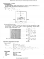
3. Effective range of plotting
1) Plotting directio'n
In reference wiih the carriage moving direction , the rightward direction is determined to be
X-axis(+) and tlte leftward direction is determined to be X-axis(- ).
2) Effective range of plotting
X-axis: 43.2mrn, 216 steps
Y-axis: Any range as determined by software.
y
- x ......·--1--...-x
y
216 neps
Effeccive range of
plotting
43.2 mm
5 mnl
9.8mm
58mm
3) Accumulative e1tror in V<1xis
As the paper is fed by means of friction with rubber for the Y-axis, there may arise a slight
deviation , which should be within a range of ±3mm as measured in the following manner,
provided that specific paper guide is in use.
Example - Programme
l0:GRAPH :
GLCURSOR <8,0>
20:""0R A=J TO 20
30:RLJNE - <0, - 200
)-(5, 0) -(0, 200
) - ( 5, 0)
40:"l£X T A
50 : RL JNE -<0, - 185
)- ( - 2 05, 0) - (0,
- J 5)
60: RLJNE - (2 ! 0,0>
-<0,- i 5> - C- 215
' 0)
4. Recording paper and ball point pens
'C!l: FJ~ O
[Recording paper)
Kind :
Din1ensions:
Ordinary paper
Paper width: 58~mm (2· 1/4")
Core size:
70mm (2·3(4"), max.
Paper length: About 55m (for the core size of 70mm)
Recommended paper: High quality paper of about 45kg with thickness of 65 to 80 micron.
( 1,000 sheets of 788 x I ,09 J mm paper equals to 45kg.)
(Weight: equivalent to 52.3 g/m 2 )
[Ball point pen)
Color:
Black, blue, red, green
Size:
5¢ x 23.3
Kind of ink:
Life:
Water color
2 50m (820 ft .) or more
2
Do not sale this PDF !!!
All and more about Sharp PC-1500 at http://www. PC-1500.info
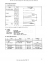
5. Electrical characteristics
5~ 1 .
Input/Output teminals
No.
Name
Color position sensor
X motor
B
I
0
A
2
0
D
3
c
4
0
B
s
0
A
6
7
Motor cornrnon
D
8
c
9
B
10
A
II
(+)
B
12
(-)
A
13
Y motor
Magnet
Circ11it diagram
~
I
f-:\.
:::(. M
~
"
,.....
:{ M\.
<>
.J
A
0
0
:
115000
I
Pen down upon current supply to the magnet in above polarity.
5-2. Magnet
J. Voltage:
2. Type:
3. DC resistance:
4. Peak current:
4.85±0.6SV
Self:holding magnet
SUbl 0% (20°C)
About I. I A (2o•c, 4 .85V)
About l.4A (0°C. S.SV, worst case)
5-3. Motor (260 steps/second)
Item
X-axis
Y-axis
o-so·c
l
Voltage
5 .85V±0.65V
2
Type
4 -phase stepping motor (2 phase excitation)
3
DC resisiance
(A l) 3on±10%
Condition
25!2±10%
2o•c
(resistance per phase)
4
5
Peak current
(per phase)
Average current
(per phase)
(A3) Abt. 0.23A
Abt. 0. 19A
Abt. 0.27A
20°c 4.ssv
ifc, S.SV, (worst 'case)
(A4) Abt. 0. 12A
(AS) Abt . 0. 16A
Abt. 0.13A
Abt. 0.18A
20°c. 4.ssv
0°C, 5.SV, (worst •Case)
JA~ Abt. O. l 6A
3
Do not sale this PDF !! !
All and more about Sharp PC-1500 at http://www.PC-1500.info
5-4. Power coniumption
Print patter
Current
Power
consptn (mA) consptn (W)
Scale
Voltage
ACll 64 character set
S=O
4.8V
soo- 550
2.4 -2 .6
ACll 64 character set (excluding CR)
4.8V
400-450
1.9 -2.2
4.2V
340- 370
1.4 - 1.6
ACJI 64 character set
S=J
S=J
S=J
5.8V
500-580
2.9 - 3.4
"5" printed in 5 columns
S=l
4 .8V
385
1.8
-
4 .8V
260
1.2
4 .8V
180
0.9
45° line drawing
(L=O)
4 .8V
490
2.4
45° dot drawing
(L= l)
4 .8V
790
3.8
ACII 64 character set
Paper feed action
X·axis forward and backward
5-5. Color position sensing switch
I. Operating voltage:
DC 24V, max.
2. Operating current:
IOOmA, max.
3. Contact resistance:
150m~, rnax.
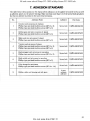
6 . D urability
Item and test method
No.
I
2
Life
6.5 million characters ASCII 64 character set
are continuously printed in the minimum
scale (S=O). At any time during the test
(ic. 1, 2, 4, and 6.5 million characters),
appearance, operating conditions. and print
quality are te·sted .
Pen life
Continuous operational test is carried out
in the print mode shown in Attached
Drawing 4-1, v.•ith a ne\v pen in use.
Test item
I. Appearance
2. Print quality
I . lnk life
Specification
Life: 6 .5 million
characiers
Must be good .
Musi be able to draw
more than 250 meters.
3. MECHANISM AND OPERATION
The printer roughly consists of six blocks - a frame, X-Oirection drive, Y-direction drive , pen drive
mechanism, color cha.ngc mechanism, and pen take-o-ut mechanism sections. An explanation of these
blocks will be given below.
1 . F rame Section
111e frame section has a side plate (right), side plate (left), holding plate, and paper guide. The
various mechanisms arc mounted both inside and outside. The lower edge of the frame is bent in the
shape of the Jetter Land acts as a mounting leg.
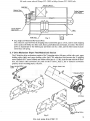
2. X Drive Mechan ism Section
The principal elements of the X-direction drive mechanism are the X stepping motor, idle gear.
bobbin gea1, pulley support base (left), pulley supp-Ori base (right), slider unit, wire, etc.
4
Do not sale this PDF !!!
All and more about Sharp PC-1500 at http://www.PC-1500.info
Stepping Motor
Idle Gear
Bobbin Gear
Pulley SUJpport
B<:ite (A. ht)
'
Pulley Support
Base (Lettt
--Wi re
Slide Unit
Fig. 1
0
• Step Angle and Minimum Movement Pitch
The reduction ratio between the stepping motor and bobbin gear is I :9.01 , and for each stepping
motor pulse (18°/360), the slider unit, that is, penX direction movement, is 0.2mm. The motive
power ls transmitted to the bobbin gear and slider unit by a wire, and the wire tension is maint;iined by a coil spring.
3. Y Drive Mechanism (Paper Feed Mechanism) Section
The Y ·direction drive mechanism consists of the Y stepping motor, idle gear, rubber roller unit, paper
holding roller (fight) and paper holding roller (left). The reduction ratio between the Y step ping
motor (called the Y motor below) and rubber roller gear is l :7.86. As is the case with the X direction, the rubber roller movement per pulse of the Y motor, that is, the Y diteclion movement
quantity of the recording paper, is 0.2mm.
Paper Holding Roller
(Left)
Fig. 2
5
Do not sale this PDF !! !
All and more about Sharp PC-1500 at http://www.PC-1500.info
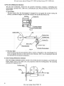
4. Pen Drive Mechanism Section
The pen drive mechanism, namely the pen up·down mechanism, comprises a self-holding type
electromagnet, ejection lever, roller lever, and baU-point pens. Pen up and down directions are as
shown below.
• Pen-up State
The pen retracts when the electromagnet is enc rgized for 5 ms against the actuator spring, and
held by a permanent magnet even after the current is cut off after the initial 5 ms.
Actuator Pin
Permanent Magnet
Actuator Rotation Center
Fig. 3
Rubber Roller
Ptn
'\'
Ejection lever
Coupling Leve.,.
Actuator Pin
R II r Lever
Recording Paper
Actuator Rotation Otnter
Fig. 4.
• Pen-down State
From its pen-up state the pen descends when a current is impressed to t he electromagnet for 5
ms in an opposite direction to that used for pen retraction. After 5 ms, the pen-down state will
be main!ained by !he actuator spring force.
5. Co lor Change Mechanism Section
The color change mechanism section consists of the X-direction drive mechanism, a pen holder and
holder stopper, both in !he slider unit, and projeccions inside the holding plates. The operating
principles are explained below.
Side Plate (Lett>
Pulley
Fig. 5
6
Do not sale this PDF !!!
All and more about Sharp PC-1500 at http://www.PC-1500.info
Holder Stopper
Wire
r--"T
'
I
~II
-T--,
I
-.I
·=~
"f._''l"E
I
I :>·r
1J
II '-'+-re-'
I I
I
I I
I
I I
I
I I
I
l
I
I
I
I
o
I
I
:
I
I
J~~~~~~~:=:=:=:=:=~L~-~-~J-~--~
I
I
i- :'--+--~-·,.__=-_j
Fig. 5
To operate the color change mechanism, first, t he slider is moved to the area a· l in Figure 6 ( 45
pulses to the left from the origin). Then, the holder stopper in the slider contacts the projection on
the holding plate, and the wedge section of the holder stopper slips out of the pen holder, which
frees it to rotate. Next, by repeating the movement of the X motor for 30 pulses each in direction
A and to the left, the pen (I) in Figure 5 changes to pen (2) . The spring moves the holder stopper to
the right until it returns to the origin. If then enters the pen holder groove. The pen holde is then
fixed, and printing is ready.
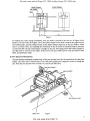
6. Pen Ejection Mechanism
The pen ejection mechanism c-onsists <.>tily of !he pen ejection lever 11131 is mounted on the side plate
(right). The slider unit is moved fully to the side plate (right) and is stopped ill order to change the
pen. Push the pen ejection lever towards you, and the pen will eject.
Pen Ejection LO'i'er.
Slidet Unit
Fig. 6
7
Do not sale this PDF !! !
All and more about Sharp PC-1500 at http://www.PC-1500.info
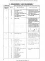
4. DISASSEMBLY AND REASSEMBLY
1. Disassembly
Remove the following parts from the frame in the sequence $hown below.
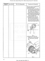
Disassembly
Sequence
Part No.
Part to be Removed
I
4-1
Electromagnet Unit
Wire Unit
Pen Take·out Bar Unit
Pulley Suppon Base (Right) Unit
Y Idle Gear
Paper Holding Roller Support
Plate (Right) Unit
•
Motor Cover
• Lift up the motor cover (7-1)
2·4
6-1
2-7
3-2
3-5
2
7-1
Point for Disassembly
•
•
Disassemble after removing
cross-recessed pan head machine
screws (SP2 x 3) and (SP2.3 x
3), and sleeves (2-5).
Note - brass fittings may slide
off. (Don't lose)
section covering the crossrecessed pan head machine
screws (SP2.3 x 3) which hold
the motor.
Remove the entire ntotor cover
(7-1) by inserting a flat-blade
screwdriver in the paper guide
as shown in the diagram below.
J
~
[!:!]
0
L
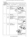
3
3-3
Rubber Roller Unit
•
4
3-1
7-4
2-3
Y Motor Unit
l'lat Wafer Assembly
Bobbin Unit
• Suction solder in the junction
•
s
2-2
X Idle Unit
3-4
Paper Holding Roller Suppon
Plate (Left) Unit
2-1
2-6
X Motor Unit
Pulley Support Base (Left) Unit
Slider Shaft (A)
Slider Shaft (B)
Slider Unit
Ejection LA:vcr Shaft Unit
Ejection Lever
Color Change
Reed Switch Unit
Rubber Bushing
Rubber Pad
2-8
2-9
4-5
4-2
4-3
4-7
<1-6
7-2
7-3
8
0
•
Push the rubber roller unit
bearing to the left and remove
from the right side of the rubber
roller unit (3-3) as it comes off
the frame unit ( I· I).
section of the two printed
circuit boards.
Note - brass fittings may slide
off. (Don't lose)
Push in plastic tabs from inside
of flame.
Do not sale this PDF !!!
All and more about Sharp PC-1500 at http://www.PC-1500.info
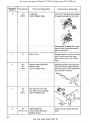
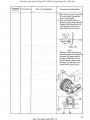
2'. Reassem bly
Reassembly can be completed most efficiently by referring to the reassembly sequence and precau·
lions shown below.
Reassembly Parts Symbol
Sequence
3· l
SP2.5 x 3
2-1
SP2.5 x 3
7-3
7-2
2
2-6
3-3
WFl.7
3.5
3
2-2
REl.5
2·.l
Parts to be Reassembled
Precautions for Reassembly
X Motor Unit
Cross-recessed Pan Head Machine
Screws
Y Motor Unit
Cross-recessed Pan Head
Machine Screws
Ru b ber Pad
Rubber Bu"1ting
Paper Holding RoUer Support
Rubber Roller Unit
Plain Washer
Paper Holding RoUer Plate
(Right) Unit
0
X Idle Gear
Type E Stopper Ring
Move the bobbin gear by one tooth
and inser t the X idle gear.
Bobbin Gear Un it
/
Recommend to engage after mark·
ing the tooth-tip and moving the
gear by one tooth.
9
Do not sale this PDF !! !
All and more about Sharp PC-1500 at http://www.PC-1500.info
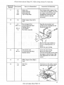
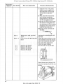
Reassembly Parts Symbol
Sequence
4
3·2
REl.5
Parts to be Reasse.mbled
Y Idle ~ar
Type E Stopper Ring
Precau lions for Reassembly
Insert the Y idle gear after moving
the paper feed gca• by one tooth.
Recommend to engage after marking the tooth tip and moving the
gear by one tooth.
5
7-1
6
4-2
4-3
RE2
Motor Cover
Hang the motor cover by its square
hole on the hook (In the paper
guide Bon the rear of the frame
unit.
Ejection [..ever Shaft Unit
Ejection Lever
Type E Stopper Ring
Insert the ejection lever shaft unit
into the frame through a bearing
hole and press in the coupling lever
from outside the frame.
~~
,,j
"'
cC:i:/
~
,;
7
6· 1
6·2
RE l.2
8
4- 7
SP!.4 x 1.6
~-
~
Pen Take·out Lever Unit
Pen Takc·out Lever Spring
Type E Stopper Ring
~
Color Change bar.
Cross-recessed Pan Head
Screws may be coaited with lock
paint.
Machine Screws
10
Do not sale this PDF !!!
All and more about Sharp PC-1500 at http:/lwww.PC-1500.info
Reassembly
Parts Symbol
Sequence
9
45
2·8
2·9
RE-2
10
2-6
11
41
SP2.5 x 3
Wf2.S
7.4
Parts to be Reassembled
Slider Unit
Slider Shaft (A)
Slider Shaft (B)
Type E Stop Ring
Precautions for Reassembly
Never bring another magnet close
to the slider unit magnet. If you do
the magnet inside the slider unit
demagnetizes causing the color
detection switch to operate
incorrectly.
Pulley Support Base (left)
Uni t
Electromagnet Unit
Cro~s.rcccsscd Pan Head
Mac hine Screws
Lock Washer
Flat Wafer Assembly
Hang the electromatnet unit
actuator on the coupling lever on
the ejection lever unit.
~~
.~
•"'
--~~~
~
Mount so that open strokes are
0 .6 mm. Clamping torque, 3 .S
kg<m.
Screw lock paint coating.
12
46
SP2x3
Screw lock paint coating.
Rotate the bobbin gear.
The reed switch must actuate when
the magnet at the left edge of the
slider approaches the closest reed
switch.
Pulley Support Base (Right}
Unit
13
14
Reed Switch Unit
Cross·recessed Pan Head
Machine Screws
2-4
2·5
Wire Unit
Sleeve
(Fig. I)
Do not sale this PDF !! !
11
All and more about Sharp PC-1500 at http://www.PC-1500.info
Reassembly Parts S.ymbol
Sequence
Parts to be Reassembled
Precautions for Reassembly
The wire must be stretched in the
order described below :
I) As shown in Fig. I , the spring
must be pressed against the side
plate using a ftnger tip with the
knot of the wire in alignment
with the side plate at point (A).
2) Next, thread the leading edge of
the wire through the puUey (B)
and the protrusion (C).
3) As shown in Fig. 2. align the
slit (D) of the bobbin gear so
that ii should on a line drawn
between the bobbin gear shaft
(E) and the idler gear shaft (F).
®
@
Fig. 2
4) Wind the wire around the
bobbin gear for one and half a
tum , then thread ii through
slits.
Fig. 3
12
Do not sale this PDF !!!
All and more about Sharp PC-1500 at http://www.PC-1500.info
Reassembly Parts Symbol
Sequence
Parts to be Reassembly
Precautions for Reassembly
5) Wind tlte wire around the pullc
(G), then thread through the
hole in the side plate.
6) Now, set the slider unit to a
distance of 5mm from the right
(magnet side), then thread the
wire through the hole in the
slider unit as shown in Fig. 4.
s ..
Fig. 4
Hold the wire at the point (A)
and stretch the wire towards the
direction (H) , then adjust the
location of the slider unit so
that the distance between the
side plate and the slider unit
should become about Smm.
©
®
13
Do not sale this PDF !! !
All and more about Sharp PC-1500 at http://www.PC-1500.info
Reassembly
Sequence
Parts Symbol
Parts to be Reassembled
Precautions for Reassembly
7) Apply the wire to the pulley
support bracket (riglit) (2·7) ,
then thread the wire Utrough
the hole in the side plate,
again.
8) Next, insen the wire into the
sleeve, thread through the
spring hook loop, then thread
the wire through the sleeve.
9) Pull the one of t he wire (i) until
the tension of I 60 grams is on
the spring (about 2mm of spring
elongation), then set the sleeve
using the long nose pliers.
IO)Check a proper movement of
the slider.
~
~
~
SP2 x 3
SP2.3 x 3
S· I
S-2
5.3
S-4
Phillips head, small, pan head
screw
Cross-recessed Pan Head Machine
Screw
llall·point Pen (lllack)
Dall·point Pen (lllue)
8all·point Pen (Green)
llall·point Pen (Red)
Securing of the bobbin gear with
the wire.
Adjust Ute relative positions of the
wire and slider so that the d rawing
line in the X·direction will be at
the center of the paper guide.
Screw lock paint coating.
Move the slider to the left edge.
JI
JI ZLT\-A
0
o~
t7'
~
"7
]
lnsert the pen tip at the tip of the
pen return spring and push the rear
section.
14
Do not sale this PDF !!!
All and more about Sharp PC-1500 at http:/lwww.PC-1500.info
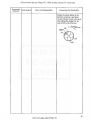
Reassembly
Parts Symbol
Sequence
Paris to be Reassembled
Precautions for Reassembly
Rotate the rotary holder in the
direction of arrow A and insert
the pen. Mount the pen color posilion making lhe magnel for the
reed switch as the reference.
Rotation
co ~rection
Magnet
Jg' D
\ 1:J
I
\J LI
Ct
-~
C2
15
Do not sale this PDF !! !
All and more about Sharp PC-1500 at http://www.PC-1500.info
5. REPAIR AND MAINTENANCE
1. Handling Precautions
1l Carrying Printer
(I) Carry the printer by hold·
ing it i_n the directions
shown by
Carrying
the printer in the
direction will cause various
troubles.
(2) The printer may be carried
by holding on to the upper
face of the motor cover
and paper guide. However,
do not apply strong
pressure to it.
iJ .
Motor Cover
Goar
Gear
...___,~l
Color
Changing bar-'
Ir
::,;:
I;
I
Elec1roi'magnet
J
Slider Unit
21 Sections where Pressure Should
Not be Applicd:
(I) Do not touch the slider unit except when taking a pen out. Particularly. never apply pressure
in the direction of rotation.
(2) Do not touch the wire. The pulley may come off.
(3) Do not touch the color changing bar. When bent , color changing cannot be accomplished.
31 Sections Not to be Touched
(I) No shaft should be touched with bare hands.
(2) Do not touch the pen return spring.
(3) Do not touch the rotary holder except when the slider is positi()ned at U1e left edge of the
frame and a pen is 1r1oun!ed.
(4) Do not touch the slider.
41 Sections Where Magnetic Substances Should be l<ept Away
(I) Do not pla.ce a magnetic substance or powder, a permanent magnet, or an electromagnet
close to the permanent magnet of the color position detector.
(2) A strong care earth magnet is used in the electromagnet unit.
51 Other;
Be very careful not to drop the pen or in any way bend ii. When the i11k is exhausted, hold by
the tail plug sect ion and shake it.
2. Maintenance
Perform repairs and maintenance as shown below to maintain U1e initial printer quality as long as
possible.
11 Cleaning
Clean the printer and remove paper dust, dirt . etc. periodically (about every Uuee months or
after using 5 rolls of recording paper).
(Points for Cleaning)
(I) Paper dust, dirt, etc. should be vacuumed up.
(Use an electric vacuum cleaner).
(2) Use alcohol or benzene when removing stains. Thinner, trichloroethylene and ketone solvent
may damage the plastic parts and should not be used.
(3) Grease any places where there is no grease or where it is not sufficient. (Do not grease unless
greasing is :required . Do not use a lubrican't except that which is specified . Refer to Item 6.
Oiling Standard.)
21 Recording Paper
( I ) Use recording paper recommended in Paragraph 24 of the specifications.
16
Do not sale this PDF !!!
All and more about Sharp PC-1500 at http://www.PC-1500.info
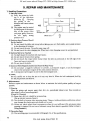
3 .. Repairs
The printer has three repair ~evels (A , B, and C) taking into account the difficulty of after sale
services and repairs. Persons in charge of repairs are asked to make repairs after comparing their own
technical proficiencies and th.e required repair level.
1) Repair Levels
Level A: A general knowledge of the principles and construction of the printer and some degree
of skill are required. l~xperience or a high degree of skill is not required.
Level B: A good knowled!ge o f the principles and construction of the printer and the skill to
disassernble the printer and to use measuring instruments, jigs, and tools accociated
with disassembly and reassembly arc required. This level requires experience in making
repairs.
Level C: A high degree of special knowledge regarding the principles and construction o f the
printer are required along with the ability to use measuring instruments, jigs, and tools
associated with the printer. ln-liepth experience ~rid skill in repair work are required.
2)
Repair Procedure
W11en a fault occurs, carefully observe and check the type of failure and the condilions surrounding it. Find out the cause and make repai" after checking the location of 1he fault, referring to the "Repair Guide."
(I) "Phenomenon"' : Determine the trouble phenomenon from 1his column.
Compare the trouble with this column and verify whether it coincides.
(2) "Condition" :
(3) "Cause ":
Causes bassed on the condition of the trouble are listed. Verify the cause .
Use the repair level described above when making repairs after fully
considering the repair level.
(4) "Locations and Methods of Checking":
TI1e column lists where to check fo.r trouble and by whal method. Check
according to the instructions in this column and locate the trouble.
(5) " Repair Method" : Repair the trouble according to t he instructions described in this column.
If the same phenomenon or condit ions cxis1 after making repairs, check
the other items in the cause coJu mn and rnake nece.ssary repairs.
3)
Repair Tools
• Screwdrivers (Precision Screwdrivers)
Phillips Type 4. equivalent to No. 000.
PltiUips Type 5, equivalent to No. 00.
Flat-blade Type 5
• ET Holders E-Ring
ET 2
ET 1.5
ET 1.2
• Radio pliers. or recd pliers
• r·weezers
• Soldering iron
Do not sale this PDF !! !
17
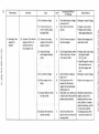
CD
Phenomenon
I. Does not draw
lines
2. Lateral lines
cannot be drawn
Condition
~use
Level
X·motor (2-1), Y-motor
(3-1) , and pen drive electromagnet (4-1) operate
normally, but no printing is
done.
Pens (5 -1 to 4) have come
off, or the ink is exhau.sted.
A
(I) X·motor (2-1) does not
rotate.
(I) X-motor lead wire is
0
:J
0
( JI
Ql
(!>
:T
-u
,,
0
(2) Abnom1ality is noticed
regardless of whether
the pen is moving up or
down.
B
cut.
(4) Foreign matter has
accumulated between
gears.
(5) Low battery voltage.
(i;"
Are the pens mounted properly? Do the pens have
enough ink?
Repair Method
Mount properly. Replace the
pens.
)>
(2) Idle gear (2·2) is deformed.
(3) Deformation of bobbin
gear unit (2-3), misalignment of !WO-piece
teeth.
0
Location and Method
of Checking
(6) Slider unit (4-5) does
not slide properly on
shaft.
(1) Foreign matter has accumulated in the moving section of the slider
B
B
Replace X-motor.
0.
3
~
Replae·e the X idle gear.
Ill
Replace bobbin gear unit.
0
c:
r:::T
-en
:::r
Ill
-a
-u
A
Rotate bobbin and unit by
hand and check for foreign
Remove foreign matter.
matter.
A
B
A
unit.
(2) Contact between pen
take-out lever unit (6-1)
and pen.
Check that a normal current
is impressed to each phase of
the motor.
Check if the X id.le gear is
normal.
Dismount wire unit (2-4),
rotate bobbin gear by hand,
and check rotation state.
Ill
:l
B
Check if battery voltage is
be.low 4.5V.
Dismount wire and move
Recharge to regular
voltage.
• Replace slide unit.
• Remove foreign matt er if
it is obstruct ing movement.
Remove any foreign matter
slider unit to the right and
left by hand.
Check that slider unit moves
smoothly on the effective
printing area 311d c heck for
an abnormal load by slov.1y
rotating the bobbin gur by
hand.
Check contact between pen
Replace pen take-out I.ever.
take-out lever and slider unit .
()
'
~
01
0
0
Ill
-
:::r
:::::
r
"O
-u
0
•
~
01
0
0
5·
O'
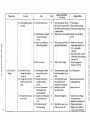
Phenomenon
Condition
Cause
Level
(3) Wire fastening position
on bobbin has mov·ed.
B
(4) Improper pulley ro ta·
tion of pulley support
base unlt(right).
(5) Sleeve (2·5) and frame
make contact.
B
B
0
0
:J
sa.
(/)
(6) X motor unit ( 2· 1) is
operating improperly.
B
( I) Wire has come off
A
(2) Wire is cut.
B
(3) Bobbin gear and wire
slip.
(4) Gear is damaged
A
Dl
(I)
(2) X·motor rotates, but
slider unit docs not
move to the right or
left.
;;;s-
u;·
-0
.,,0
3. Insufficient
Lateral Movement
( I ) Operates in pen-down
mode only, and not
normal.
(1) Rubber roller unit
(3-3) is scratched.
A
c
Location and Method
of Checking
Rotate bobbin gear unit (2·3)
by hand and check that
slider unit moves smoothly
from left edge to righ t edge.
Dismount wire from pulley
and check fo r smooth
rotation.
Check for deformation
between frame unit and
sleeve, as well as for other
phenomena.
Dismount X idle gear (2·2),
slowly rotate motor gear,
and check for abnormal load.
Check if wire has come off
the bobbin gear.
Check that wire has not been
cut.
Confirm that wire is properly
screwed on to bobbin gear.
Check that X idle gtar and
bobbin gear are operating
properly.
Slowly rotate the rubber
roller by hand and check for
scratches and fo reign matter .
Repair ~le thod
Restretch wire if its fasten·
ing position is wrong.
)>
Replace pulley support base
unit .
Repalce sleeve.
~
ID
A
B
Check the surface of the
print paper.
Check the contact between
the ejec tion lever and
ejection roller ( 4-4 ) .
a.
3
0
iil
Q)
er
0
-en
c
Replace motor.
:::1'
Ill
-a
Restretch wire properly .
-0
()
Replace wire unit.
'
c.n
• Tighten the screws.
• Replace the bobbin gear
-
~
unit.
• Replace damaged gear.
• Replace rubber roller
unit if scratches are
fo und.
• Remove foreign matter.
(2) Print paper has
irrcgulations.
(3) Deformation of ejection
lever shaft unit (4-2).
Ill
::i
Use normal print paper.
• Replace ejection lever
shaft unit.
0
0
Q)
:::1'
::::
r
"
-0
()
•
~
c.n
0
0
::i
O'
"'0
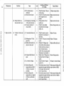
Phenomenon
Condition
Cause
Level
(4) Low battery voltage
A
(5) Contact between setscrew of return spring
and small roUer.
A
Location and Method
of Checking
Check that bat tery voltage is
not below 4.5V.
~love slider and confirm
contact.
Repair Method
Recharge to normal voltage.
• Replace rotary holder.
• Replace paper holding
roller support plate u nit.
)>
Q)
::>
4. Drawing is done
segment by
segment
0
0
:J
0
(I) Actuator oft he electromagnet unit ( 4· I) is
detached from the
electromagnet coil.
(I) Current is not being
supplied to the electro.
magnet properly.
A
Check if current is going to
the electromagnet .
(2) Abnormally large
electromagne t energize
stroke.
B
Check if gap between rubber
roller and pen tip is 0.6mm
in the pen·up mode.
CD
-u
.,,
0
0.
3
0
a;
Q)
I Jl
Ql
: :r
(ii'
Replace electromagnet and
repair drive circuit .
(3) Low battery voltage
(4) Eleclromagnet unj( is
faulty.
(5) Rotary holder on slider
A
B
/\.
unit has moved.
(6) Ejection lever does not
operate smoothly.
c
Check if battery voltage is
below 4.SV.
Check operation of the
actuator for the electro·
magnet unit, spring fatigue,
deformation , etc.
Check that rotary holder pen
is directly above the specified
position (print position) .
• Replace with a pen having
the standard length
(23.3~~ 1 mm).
• Adjust the gap by turning
the mounting screw o n
the electromagnet unit
(4·1).
Recharge to normal voltage.
cr
0
c
UJ
::r
,
Q)
"O
-0
()
'
~
(.11
0
0
i
Q)
Replace electromagnet unit.
Manually rnnintain electro·
rnagnel actuator in the
energized position, rotate
rotary holder in a counterclockwise direction. and fix
It in iu proper position .
Check for a bend in the
• Exchange ejection lever
ejection lever shaft unit .
ejection lever and inspect the
bearing section.
::r
::::
"O
:::::
-0
0
'
~
(.11
0
0
::>
0
Phenomenon
Condition
Cause
Level
(2) Electromagnet operates
normally
(I) Pen movement is slow.
B
(2) Deformation and fatigue
of pen return spring
(4-5-3).
(3) Paper is not winding on
0
B
A
rubber roller properly.
0
:J
0
L~ation
and Method
of Checking
Check the shape o! the pen
Also check for rotary holder
deformation and the presence
of foreign ma11er.
Inspect the pen return spring.
Remove paper andl check for
paper guide dcfonnation,
( JI
Ql
(!>
(4) Pen istoo long,
; :J"
c;;·
A
Measure the pen length.
-u
.,,0
5. Color does nor
Ch.an~
(I) Pen moves 10 color
change area without
moving up.
(2) Carriage docs not move
until it reaches the left
edge.
(3) RotaJ)' holder does not
rotate at all.
-"'
(1) Elecrromagnet induced
pen up function is abnormal.
{I) foreign matter has ac·
cumulated in slider
section.
(2) Contact between slide
shaft support plate
(4-5-5) and frame_
(I) Fatigue and deformation
of color chanse bar.
(4-7).
(2) Pe11 rip has come off
the return spring.
B
Check transmission system
from elec!Iomagnet to pen
Repair Method
• Pen exchange.
• Rotary holder exchange.
• Removal of foreign matter.
QI
Repalce rotaJ)' holder set
(4·5·2).
• Return it to its normal
shape using tweezers. etc.
if it is only slightly
deformed.
• Remount properly if small
roller which holds the paper
haJ come off.
• Mount a proper pen
(leng01 23.3~?mm)
~e Phenomenon 4.
B
Check for foreign matter.
Check if sllder moves
smoothly by rot at Ing the
bobbin gear by hand.
Check for contact.
:::J
0.
3
~
Dl
er
0
c:
-en
:::r
QI
-a
-u
()
_.
'
01
0
0
Dl
:::r
:::
drive.
A
)>
Remove foreign matter and
exchange slider unit.
Replace slider unit.
r
"
-u
()
_.
•
01
B
B
Check color change bar.
Check all four pc111 to see
if they have come off.
• Gently lift color chan~
bar using tweezers.
• Replace color change click.
• Repair using tweezers.
• Replace rotary holder if
rctum spring is deformed.
0
0
5·
O'
I\)
I\)
Phenomenon
Condition
Cause
Level
(3) Pen return spring is
deformed.
(2) Reed switch is faulty
B
(1) Discrepancy in mounting
B
B
Location and Method
of Checking
Repair Method
Check the shape of the pen
• Replace rotary holder.
return spring.
Check if reed switch actuates Replace reed switch unit
when magnetic nux is
(4·6).
norm a.I.
(3) Rotary holder rotations arc short by one
of the reed switch unit.
(2) Excessive rotation of
rotary holder.
A
Check position of reed
switch unit.
Check if rotary holder
excessively due to foreign
maner, etc.
Replace reed switch unit.
)>
Q)
::>
Remove foreign malle1, etc.
0.
3
0
a;
Q)
0
0
:J
-
7. Paper is not fed.
(I) Y motor (3·1) does not
rotate.
(I) Y motorlead wire is cut.
B
0
I Jl
Ql
CD
: :r
(ii'
(2) Deformation of Y idle
gear (3·2).
(3) Rubber roller unit (3·3)
does not rotate well.
B
B
-u
.,,
0
(4) Foreign matter between
gears.
A
(5) Low battery voltage.
A
(6) Paper holding roller
support plate unit (left)
(3-4) does not operate
smoothly.
(7) Paper holding roller
support plate unit ( right)
(3-5) does not function
well.
B.
B
Check if normal current is
impressed to each phase of
the motor.
Check if Y idle gear is normal
or not.
Dismount Y idle gear and
check rubber roller rotations.
Cautio n rotations are heavy
due to friction be tween
rubber roller and paper guide
when paper is not inserted.
Slowly rotate Y idel gear by
hand and check for foreign
matter.
Check if battery voltage is
below 4.5V.
Hook tweezer tips in hole of
spring hook on paper holding
roller support plate unit and
move it up and down.
Hook tweezer tips in hole of
spring hook on paper holding
roller support plate unit and
move it up and down.
Replace X motor.
cr
0
c
UJ
::r
Replace Y idle gear.
Replace rubber roller u nit.
,
Q)
-0
-0
()
'
~
(.11
0
0
i
Q)
::r
::::
Remove foreign matter.
Recharge to normal voltage.
-0
:::::
-u
'
0
Replace paper holding roller
support plate unit (left).
~
(.11
0
0
::>
0
Replace paper holding roller
support plate unit (right}.
Phenomenon
Condition
Cause
Level
( 2) Paper and rubber roller
slip.
(1) Damage to paper hold-
A
ing roller (large) (3-6)
and paper holding roller
(small) (3-7).
(2) Defonnation of paper
guide.
(3) Foreign matter in paper
guide.
-
8. Y-direction
movement is
insufficient.
I Jl
Ql
CD
: :r
(ii'
-0
.,,
0
(I) Character alignment o n
one line is bad, and
the line rises at the
right end.
(2) Stepping error in
Y-direction.
c
A
( I ) Roll paper load is too
heavy.
A
(1) Y drive mechanism gear
B
is damaged .
( 2) Sliding paper feed gear,
by one tooth, gear ing
of rubber roller unit is
not enough.
(3) Rubber roller unit
A
B
bearing is worn.
( 4) Low battery voltage.
~
Replace damaged rolle1.
Q)
0
:J
Check if paper holding
roller is there.
Repair Method
)>
0
0
Location and Method
of Checking
A
=>
a.
Check for paper guide
defonnation.
Check for foreign matter in
paper guide and for inscrtion of paper.
Replace paper guide.
Check that roll paper is
guided smoothly into the
printer.
Repair roll paper guide.
-
Check Y idle gear (3-2),
rubber roller unit (3-3) gear,
and Y motor unit (3· I ) gear.
Check that the two-piece
tooth gear on rubber roller
unit is engaging after being
slid by one too th .
Move rubber roller unit gear
up and down by h and and
check for play .
Replace gears.
,
-0
-u
()
'
Check if battery voltage is
below 4.5V.
3
Remove foreign matter.
0
a;
Q)
O'
0
c
UJ
::r
Q)
~
(.11
0
0
i
Q)
Mount after setting it
properly .
::r
::::
-0
:::::
• Replace rubber roller unit
if wear is noticed.
• Fix by using a cyanoacrylate adhesive when
there is play between the
bearing and frame.
• Replace printer.
Recharge to regular voltage.
-u
()
'
~
(.11
0
0
=>
0
~
Condition
Cause
Level
(3) Origin position differs
after making many
movemtnts in Y dircction. Origin position
changes after printing
a large number of
characters.
(1) Rubber roller and paper
slip.
A
Phcnon1enon
0
-
OJ
:>
A
A
0
( J)
Ill
Cl>
Wipe off rubber roller stain.
a.
(3} Roll paper is guided
improperly.
:J
Check for slaincd rubber
roller.
Repair Method
)>
(2) Defom1ation of paper
guide.
0
Location and Method
of Checking
(4) Paper type does not
match printer.
A
Check paper guide .
Check roll paper rot at ion
and ensure that the center
of the paper and tl1e center
of the pnnter are aligned .
Check that the specified
paper is used.
• Repair paper guide if
there 1s any deforma tion.
• Replace printer.
Repair roll paper guide.
"U
0
Tl
<n
OJ
cr
-
0
c
( /)
::r
OJ
~
'O
Use the specified paper.
-0
0
•
~
" ;J
u;·
3
0
CJl
9. Character misalignment is
substantial.
( l) "F" is drnwn as shown
below.
f
(1) Improper engagement
of bobbin gear uni t
(2·3) after sliding b y
one tootl1.
(2) Rotary holder and
slidcr do not lock
sufficie ntly.
(3) Play between pen return
A
Mount properly.
0
0
OJ
: :r
::::
'O
B
B
Check ro tary holder play
by rotating it slow ly by
hand.
Check by rotating X bobbin
Exchange slider unit.
:::::
Replace rotary holder.
()
B
several seconds by hand in
the pen-down onode.
Check for slack in wire
~-u
'
gear back and for1Jt for
spring ~nd JX'll tips.
(4) Wire spring fatigue in
wire unit (2-4). clonga·
tion of wire.
Check gea r engagement.
~
CJl
0
0
Replace wire unit.
:>
0
Phenomenon
Condition
(2) "F" is printed as shown
below.
FF
OK
NG
(3) ··P" is shon as shown
below.
0
0
p F
:J
0
I Jl
Ql
OK
NG
Cause
(I) Pen and return spring.
Level
B
(2) Play in entire slider.
B
(1) Faulty engagement of
paper feed gear insjde
rubber roller unit
after sliding by one
tooth.
(2) Substantial play in
rubber roller bearing.
A
Location and Method
of Checking
Repair Method
Check by rotating Y idle gear Replace rotary holder.
back and forth for several
seconds by hand in the pendown mode.
Check slider and X drive
Exchange slider.
system.
Check gear engagement.
Mount properly.
)>
Q)
=>
a.
3
0
a;
Q)
cr
0
c
UJ
B
Check for play by moving
the gear vertically.
Replace rubber roller unit.
::r
,
Q)
"O
"U
CD
()
: :r
(ii'
-0
'
~
<.n
0
0
i
.,,
0
Q)
::r
::::
"O
:::::
"U
()
'
~
<.n
0
0
=>
0
..,
"'
All and more about Sharp PC-1500 at http:/lwww.PC-1500.info
6. OILING STANDARD
Two types of oil arc used in this printer - G488 and CRC S-56. When oiling during disassembly and re·
assembly. thorouiltly clean the parts and oil in accordance with the table below.
No.
Oiling Location
Oil Type
Pan code
(I)
Area of contact between paper holding roller support
plate (left) and side plate.
Contact section between paper holding roUer support
plate (right) and side plate,
Sliding sections (4 locations) between paper holding
roller and roller maft.
Sliding section between rubber roller unit shaft and
plain washer.
Contact section between plain washer and side plate.
Sliding section between ejection lever shaft u;lit and
slide plate.
Sliding section between ejection roller and slider
set.
Tooth section of X idle gear.
Tooth section of Y idle gear.
Sliding section between holder stopper and holding
plate.
Electromagnet unit actuator shaft.
Slider shaft (A)
Slider sltaft (B)
G-488
UJ<OG-0 I 08CSZZ
G-488
UKOG-0 IOSCSZZ
G-488
UKOG-0 IOSCSZZ
G-488
UKOG-0 I08CSZZ
G-488
G-488
UKOG-0108CSZZ
UK0G-0!08CSZZ
G-488
UK0G-Ot08CS72
G-488
G-488
G-488
UJ<OG-0108CSZZ
UKUG-0 I08CSZZ
UKOG-0108CSZZ
G-488
CRC5-56
CRC5-56
UKOG-0 I08CSZZ
UK0G-0098CSZZ
UKOG-0098CSZZ
(2)
(3)
(4)
(5)
(6)
(7)
(8)
(9)
(10)
(11)
(12)
(13)
26
Do not sale this PDF !!!
All and more about Sharp PC-1500 at http://www.PC-1500.info
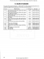
7. ADHESION STANDARD
The table below shows points on the clamps where adhesion is to be applied to lock the screws as well
as adhesion points on the printer bearings. Make sure that more than 1/4 of the screw heads are glued,
bu t that no adhesive is present in the screw head recessions.
Adhesive
Part Code
I
X motor unit set-screws in 2 places
Phillips type pan head machine screws (SP2.3 x 3)
Phj)Jjps type pan head machine screws (SP2 x 3)
Screw lock
UKOG-0003SCZZ
2
Bobbin gear unit wire set·screws (I place)
Phillips type pan head machine screws (SP2 x 3)
Screw lock
UKOG-0003CSZZ
3
Slider unit wire set-screws ( J place)
Phillips type pan head machine screws (SP2 x 3)
Screw Jock
UKOG-0003CSZZ
4
Y motor unit set-screws 2 places
Phillips type pan head machine screws (SP2.3 x 3)
Phillips type pan head machine screws (SP2 x 3)
Screw lock
UKOG-0003CSZZ
5
Electromagnet unit se l ·screws in one place
Phillips type pan head machine screws (SP2.5 x 3)
Screw Jock
UKUG-0003CSZZ
6
Reed switch unit set-screws in one p1ace
Phillips type pan head machine screws (SP2 x 3)
Screw Jock
llKOG-0003CSZZ
7
Color chanse bar set-screws
Phillips type pan head machine screws (SP J .4 x I .6)
Screw lock
UKOG-0003CSZZ
Cyanoacrylate
UKOG-0032CSZZ
No.
8
Adhesion Point
Rubber roller unit bearing and side plate
adhesive
27
Do not sale this PDF !! !
All and more about Sharp PC-1500 at http://www.PC-1500.info
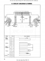
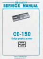
8. CIRCUIT DIAGRAM & WIRING
2 3 1 5 6 7 8 9 10 11 12 13
0
00
0
0 0 00 00
Jumper
Sieck
Yellow
Name
Reed-$Wlleh
Solenoid
No.
Color
8
detecto r
A
2
D
3
c
1
8
5
A
6
Slack
Red
Yellow
Circuit diagram
~
positon
0
X-Motor
Motor
common
0-
7
D
8
c
9
8
10
A
1I
(+)
B
I2
(- )
A
13
M
Y·Motor
Solenoid
:
roooo~
28
Do not sale this PDF !!!
Re<l
Blue
White
All and more about Sharp PC-1500 at http://www.PC-1500.info
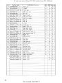
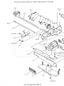
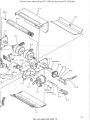
9. PARTS GUIDE AND PARTS LIST
29
Do not sale this PDF !! !
All and more about Sharp PC-1500 at http://www.PC-1500.info
NO.
1- 1
2- 1
2- 2
2- 3
2- 4
2- 5
2-6
2- 7
2- 8
2-9
3-1
3- 2
-3- 3
3- 4
3- 5
3- 6
3- 7
4- 1
4- 2
4- 3
4- 4
4-S
4-6
4- 7
6- 1
6-2
6- J
7- 1
7- 2
i..:--:7- 3
PARTS CODE
OOPDG053 / / ///
OOPDG005 / / / / /
OOP07- -0 132- 0 1
OOPDGO l 3 // / / /
OOPDG020 / / / / /
OOP26--000l - O I
OOPDGOl5 / / / / /
OOPDGO l 9 // / //
OOPI0--0335- 0 1
OOP I0- 0336- 0 1
OOPDG006 / / / / /
OOP07- 013 1- 0 I
OOPDG0 0 9 /// / /
OOPDGO IO // / / /
OOP DGO I I I I I I I
OOP I0 - 0297-0 1
OOP I0 - 0 2 96- 0 1
OOPDG025 / / / / /
OOPDG030 / / / / /
OO P l2- 0 147- 01
OOPI0- 0287- 0 1
OO P DG059 / / / / /
OOPDG063 / / / / /
OOPl9-02 19- 02
OOPDG060 / / / / /
OOP l 9-02 14 - 02
OO P I 1-0062-02
OOP I 1- 0045- 0 I
OO P23- 0018- 01
OOP23- 0017-0 1
OOPC B68 185 / / /
ME W
D E SC R I P TI ON
Frame unit
~iear
PARlS
AAHK
c
PRCE RAn<
N
a
B B
B B
A E
- NN
X n'lOtor
X idler
MAAK
B
Bobbin ~1ear unit
N
B
A K
\Vire uni1
N
B
A F
Sleeve f or wire
N
c
A
(Left)
Pulley unit (Right)
Shaft A
Shaft B
N
c
A p
N
c
A
N
c
A F
N
c
A
B
8 B
A E
Pulley unit
[N
Y motor
Y idler ~ea r
c
N
F
N
B
- NN
A
s
- AA
p
Paper pressure roller A
N
c
c
c
c
8
N
c
A
Magnet un.it
N
8
A
Push le ver uni1
N
c
A
Joint lover
N
c
A F
N
I c
A
Slider head unil
Read SW. sunit
N
B
A
N
8
A
Pawl anQ!e
N
A
L
Pen eject lever
N
A
K
Pen eject spring
N
A
D
Pen eject plate
N
c
c
c
c
c
c
A
G
Rubber fOller unit
Paper plaic (Left)
Paper plat e (Ri~h t)
N
Paper pressure roller
I
Push rOller
I
Motor covet
Rubber bushins1 c1,..1shion
OOP24- 0 2 09-0I
Rubber pad cushion
Washer (3.0)
Washer (2.5)
OOP23- 00 2 5- 01
Washer (1. 7)
-
N
N
N
A
p
D
0
u
L
E
x
·T
A N
A
c
A
c
c
A
A
G
A A
c
A
I c
A
-
30
Do not sale this PDF !!!
All and more about Sharp PC-1500 at http:f/www.PC-1500.info
1-1
2 -9
/
/
l - I
7- 2
Do not sale this PDF !! !
All and more about Sharp PC-1500 at http://www. PC-1500. info
7- I
I
•
@
1-1
i
.. .,,.
2-1
'
;
' 1
~/SPI 4XJ.6
•
I
';
7-3
•
S P2.3X 3
/
.~~; i~'.\M,~~~--/l'~~@
11
/
M
"""
H
/
, I :,.,. ~~
~~< "- ~Q,<Ii,'=',....,,~
,
~ -.},4~1~
•.• "'.
-~
/~
ti - ~'
""'
,_,
"f"'"P ~~
,_
5
/
,_,
~
~ul
SP~5 X 32-
~
4
"5
.~
\
2- 5
2-7
. PDF ...
111
Do not sa Ie this
31