1
HP SureStore E Disk Array 12H
System Administrator’s Guide for
HP-UX, MPE, and Microsoft Windows NT
with AutoRAID™ Technology
HP Part Number C5445-90902
Printed in U.S.A.
September 1999
Notice
Copyright © 1997, 1998, 1999 Hewlett-Packard Company
The information contained in this document is subject to change without notice.
Hewlett-Packard Company makes no warranty of any kind with regard to this material, including, but not
limited to, the implied warranties of merchantability and fitness for a particular purpose. Hewlett-Packard
shall not be liable for errors contained herein or for incidental or consequential damages in connection with
the furnishing, performance, or use of this material.
This document contains proprietary information, which is protected by copyright. All rights are reserved.
No part of this document may be photocopied, reproduced, or translated to another language without the
prior consent of Hewlett-Packard.
Print History
Edition 1, May 1997
Edition 2, January 1998
Edition 3, May 1998
Edition 4, August 1998
Edition 5, February 1999
Edition 6, June 1999
Edition 7, September 1999
Typographical Conventions
NOTE! Notes contain important information.
CAUTION! Caution messages indicate procedures which, if not observed, could result in
damage to your equipment or loss of your data.
WARNING! Warning messages indicate procedures or practices which, if not observed,
could result in personal injury.
2
About this Book
This book describes the tasks and tools involved in managing the HP SureStore E Disk Array 12H on HP
UX, MPE, and Windows NT . This material is intended for system administrators and others involved in
the installation, operation, and management of network storage. The content of this book is organized as
follows:
The first section describes the tasks involved in managing the HP SureStore E Disk Array 12H on HP-UX.
•
Chapter 1 provides an overview of the management tools, system requirements, and software
installation.
•
Chapter 2 describes how to use the HP-UX System Administration Manager (SAM) to manage the disk
array.
•
Chapter 3 describes how to manage the disk array using the HP-UX ARM command line utilities.
•
Chapter 4 explains how to use the ARDIAG Offline Diagnostic to isolate and solve disk array
problems.
The next section describes the tasks involved in managing the HP SureStore E Disk Array 12H on MPE.
•
Chapter 5 provides an overview of the management tools, system requirements, and software
installation.
•
Chapter 6 describes how to manage the disk array using the MPE ARM command line utilities.
•
Chapter 7 explains how to use the ARDIAG Offline Diagnostic to isolate and solve disk array
problems.
The last section describes management of the HP SureStore E Disk Array 12H on Windows NT.
•
Chapter 8 provides an overview of the system requirements and software installation.
•
Chapter 9 describes how to use the AutoRAID Manager for Windows to manage the disk array.
•
Chapter 10 describes how to manage the disk array using the Windows NT ARM command line
utilities.
During installation of the AutoRAID Manager for Windows NT software, an electronic copy of this book in
Adobe Acrobat format is included in the Program Files\AutoRAID\Doc directory (default
location).
3
Supporting Documentation
The following documentation is included with the HP SureStore E Disk Array 12H and should be available
for reference when installing and managing the disk array.
•
HP SureStore E Disk Array 12H User’s and Service Manual, part number C5445-90901
For Windows NT users, an electronic copy of this book in Adobe Acrobat format is included in the
Program Files\AutoRAID\Doc directory.
Trademark Credits
AutoRAID™ is a trademark of Hewlett-Packard Company.
Microsoft Windows and Microsoft Windows NT are registered trademarks of Microsoft Corporation.
HP on the World Wide Web
The latest information about your HP SureStore E Disk Array 12H is available on the HP web site at
www.hp.com/go/support
Check our web site for
•
Updated editions of product documentation
•
Firmware and software upgrades
•
Current supported system configurations
•
General information for optimizing the operation of your disk array
4
Table of Contents
CHAPTER 1. MANAGING THE HP SURESTORE E DISK ARRAY 12H ON HP-UX.................... 13
DISK ARRAY MANAGEMENT TOOLS .......................................................................................................... 14
System Administration Manager (SAM)............................................................................................... 14
AutoRAID Management (ARM) utilities.............................................................................................. 14
Disk array control panel........................................................................................................................ 14
WHICH TOOLS TO USE FOR EACH TASK .................................................................................................... 15
INSTALLING THE DISK ARRAY MANAGEMENT SOFTWARE ......................................................................... 16
Operating System Support .................................................................................................................... 16
IPR Program ......................................................................................................................................... 16
TIPS FOR CONFIGURING THE DISK ARRAY ON HP-UX............................................................................... 17
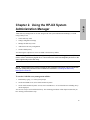
CHAPTER 2. USING THE HP-UX SYSTEM ADMINISTRATION MANAGER .............................. 19
SELECTING HARDWARE PATHS ON HP-UX 10.20 ..................................................................................... 20
CONFIGURING A NEW DISK ARRAY ........................................................................................................... 23
CHECKING DISK ARRAY STATUS ............................................................................................................... 24
CHANGING DISK ARRAY CONFIGURATION SETTINGS ................................................................................. 24
MANAGING LUNS (LOGICAL DRIVES) ....................................................................................................... 25
Checking LUN Configuration............................................................................................................... 26
Creating a LUN..................................................................................................................................... 26
Deleting a LUN..................................................................................................................................... 27
ADDING A DISK.......................................................................................................................................... 28
Including a Disk.................................................................................................................................... 29
Downing (Excluding) a Disk ................................................................................................................ 30
REBUILDING THE DISK ARRAY................................................................................................................... 31
Setting Rebuild Priority ........................................................................................................................ 31
SWITCHING PRIMARY CONTROLLERS......................................................................................................... 32
CHAPTER 3. USING THE ARM COMMAND LINE UTILITIES FOR HP-UX................................ 33
INFORMATION IN MAN PAGES ..................................................................................................................... 33
COMMAND SYNTAX CONVENTIONS ........................................................................................................... 34
THE ARMSERVER PROCESS ...................................................................................................................... 34
THE ARRAY MONITOR DAEMON (ARRAYMOND) ....................................................................................... 35
Routing arraymond Error Messages...................................................................................................... 35
SELECTING A DISK ARRAY TO MANAGE .................................................................................................... 36
CONFIGURING A NEW DISK ARRAY ........................................................................................................... 37
CHECKING DISK ARRAY STATUS ............................................................................................................... 39
DISPLAYING DISK ARRAY SERIAL NUMBERS ............................................................................................. 40
CHANGING DISK ARRAY CONFIGURATION SETTINGS ................................................................................. 40
5
MANAGING LUNS (LOGICAL DRIVES) ....................................................................................................... 42
Checking LUN Configuration ............................................................................................................... 42
Creating a LUN ..................................................................................................................................... 42
Renumbering a LUN ............................................................................................................................. 43
Deleting a LUN ..................................................................................................................................... 43
ADDING A DISK .......................................................................................................................................... 44
Including a Disk .................................................................................................................................... 45
REBUILDING THE DISK ARRAY ................................................................................................................... 46
Rebuilding the Disk Array Manually .................................................................................................... 46
Setting Rebuild Priority......................................................................................................................... 46
Checking the Progress of a Rebuild ...................................................................................................... 47
Canceling a Rebuild .............................................................................................................................. 47
ANALYZING DISK ARRAY PERFORMANCE .................................................................................................. 48
Command Examples.............................................................................................................................. 48
Selecting a Time Period for Analysis.................................................................................................... 49
Checking the Working Set Metric......................................................................................................... 49
PERFORMING DISK ARRAY MAINTENANCE TASKS ..................................................................................... 50
Shutting Down the Disk Array .............................................................................................................. 50
Restarting the Disk Array...................................................................................................................... 50
Resetting the Disk Array ....................................................................................................................... 51
Downing (Excluding) a Disk................................................................................................................. 51
Testing a Disk ....................................................................................................................................... 52
Displaying Test Results......................................................................................................................... 52
Canceling a Disk Test ........................................................................................................................... 53
Printing ARMServer Log Contents ....................................................................................................... 53
Displaying Hardware Logs.................................................................................................................... 53
Formatting the Disk Array..................................................................................................................... 54
Changing SCSI Settings ........................................................................................................................ 55
Changing the Controller SCSI ID.......................................................................................................... 55
Switching Primary Controllers .............................................................................................................. 55
Setting Data Resiliency ......................................................................................................................... 56
Creating a Disk Array Alias .................................................................................................................. 58
DOWNLOADING FIRMWARE........................................................................................................................ 59
Firmware Download Procedure With LVM.......................................................................................... 60
RECOVERING DATA MAPS ......................................................................................................................... 62
VIEWING THE DISK ARRAY GENERAL CONFIGURATION SETTINGS ............................................................. 64
Simplified Resiliency Setting ................................................................................................................ 70
CHAPTER 4. USING THE ARDIAG OFFLINE DIAGNOSTIC ON HP-UX...................................... 73
OPERATING ENVIRONMENT ........................................................................................................................ 73
Support Software................................................................................................................................... 73
Minimum hardware ............................................................................................................................... 73
6
Minimum software ................................................................................................................................ 73
DEFINITION OF TERMS ............................................................................................................................... 74
ARDIAG OPERATIONAL COMMANDS ....................................................................................................... 75
ARDIAG INTERFACE COMMANDS ............................................................................................................ 76
OPERATIONAL COMMAND DESCRIPTIONS .................................................................................................. 77
CLRLOG .............................................................................................................................................. 77
DELETELUN ....................................................................................................................................... 78
DESCRIBE ........................................................................................................................................... 79
DOWNLOAD....................................................................................................................................... 81
FORMAT.............................................................................................................................................. 85
INQUIRY ............................................................................................................................................. 87
READLOG ........................................................................................................................................... 88
RECOVER............................................................................................................................................ 92
REQSENSE .......................................................................................................................................... 94
RESTART ............................................................................................................................................ 95
REVISION............................................................................................................................................ 96
ROMT................................................................................................................................................... 97
SETOPTIONS ...................................................................................................................................... 99
SHUTDOWN ..................................................................................................................................... 102
WRTMT ............................................................................................................................................. 103
INTERFACE COMMAND DESCRIPTIONS ...................................................................................................... 105
DISPMAP ........................................................................................................................................... 105
DISPMECH ........................................................................................................................................ 106
RANGE............................................................................................................................................... 107
SHOWENV ........................................................................................................................................ 108
TESTDISK ......................................................................................................................................... 109
TESTLEVEL ...................................................................................................................................... 110
ODE INTERFACE ...................................................................................................................................... 111
ARDIAG INTERFACE TO ODE................................................................................................................. 113
CHAPTER 5. MANAGING THE HP SURESTORE E DISK ARRAY 12H ON MPE...................... 115
DISK ARRAY MANAGEMENT TOOLS ........................................................................................................ 116
AutoRAID Management (ARM) utilities............................................................................................ 116
Disk array control panel...................................................................................................................... 116
WHICH TOOLS TO USE FOR EACH TASK .................................................................................................. 117
INSTALLING THE DISK ARRAY MANAGEMENT SOFTWARE ....................................................................... 118
Operating System Support .................................................................................................................. 118
TIPS FOR CONFIGURING THE DISK ARRAY ON MPE ................................................................................ 119
CONFIGURING AUTORAID SCSI LUNS FOR MPE/IX ............................................................................. 121
Configuration Requirements ............................................................................................................... 121
MPE/iX SYSGEN Configuration ....................................................................................................... 122
Device Adapter Configuration: ........................................................................................................... 123
7
SCSI Target Configuration: ................................................................................................................ 123
LDEV (SCSI LUN) Configuration...................................................................................................... 124
CHAPTER 6. USING THE ARM COMMAND LINE UTILITIES FOR MPE.................................. 125
SETTING UP MPE POSIX SHELL ............................................................................................................. 125
INFORMATION IN MAN PAGES ................................................................................................................... 126
COMMAND SYNTAX CONVENTIONS ......................................................................................................... 126
THE ARMSERVER PROCESS .................................................................................................................... 127
SELECTING A DISK ARRAY TO MANAGE................................................................................................... 128
CONFIGURING A NEW DISK ARRAY .......................................................................................................... 129
CHECKING DISK ARRAY STATUS.............................................................................................................. 131
DISPLAYING DISK ARRAY SERIAL NUMBERS ........................................................................................... 132
CHANGING DISK ARRAY CONFIGURATION SETTINGS ............................................................................... 132
MANAGING LUNS (LOGICAL DRIVES) ..................................................................................................... 134
Checking LUN Configuration ............................................................................................................. 134
Creating a LUN ................................................................................................................................... 134
Renumbering a LUN ........................................................................................................................... 135
Deleting a LUN ................................................................................................................................... 135
ADDING A DISK ........................................................................................................................................ 136
Including a Disk .................................................................................................................................. 136
REBUILDING THE DISK ARRAY ................................................................................................................. 138
Rebuilding the Disk Array Manually .................................................................................................. 138
Setting Rebuild Priority....................................................................................................................... 138
Checking the Progress of a Rebuild .................................................................................................... 139
Canceling a Rebuild ............................................................................................................................ 139
ANALYZING DISK ARRAY PERFORMANCE ................................................................................................ 140
Command Examples............................................................................................................................ 140
Selecting a Time Period for Analysis.................................................................................................. 141
Checking the Working Set Metric....................................................................................................... 141
PERFORMING DISK ARRAY MAINTENANCE TASKS ................................................................................... 142
Shutting Down the Disk Array ............................................................................................................ 142
Restarting the Disk Array.................................................................................................................... 142
Resetting the Disk Array ..................................................................................................................... 143
Downing (Excluding) a Disk............................................................................................................... 143
Testing a Disk ..................................................................................................................................... 144
Displaying Test Results....................................................................................................................... 144
Canceling a Disk Test ......................................................................................................................... 145
Printing ARMServer Log Contents ..................................................................................................... 145
Displaying Hardware Logs.................................................................................................................. 145
Formatting the Disk Array................................................................................................................... 146
Changing SCSI Settings ...................................................................................................................... 147
Changing the Controller SCSI ID........................................................................................................ 147
8
Switching Primary Controllers............................................................................................................ 148
Setting Data Resiliency....................................................................................................................... 148
Creating a Disk Array Alias................................................................................................................ 150
DOWNLOADING FIRMWARE ..................................................................................................................... 151
Firmware Download Procedure .......................................................................................................... 152
RECOVERING DATA MAPS ....................................................................................................................... 153
VIEWING THE DISK ARRAY GENERAL CONFIGURATION SETTINGS ........................................................... 155
Simplified Resiliency Setting.............................................................................................................. 161
CHAPTER 7. USING THE ARDIAG OFFLINE DIAGNOSTIC ON MPE ....................................... 165
OPERATING ENVIRONMENT ...................................................................................................................... 165
Support Software ................................................................................................................................ 165
Minimum hardware............................................................................................................................. 165
Minimum software .............................................................................................................................. 165
DEFINITION OF TERMS ............................................................................................................................. 166
ARDIAG OPERATIONAL COMMANDS ..................................................................................................... 167
ARDIAG INTERFACE COMMANDS .......................................................................................................... 168
OPERATIONAL COMMAND DESCRIPTIONS ................................................................................................ 169
CLRLOG ............................................................................................................................................ 169
DELETELUN ..................................................................................................................................... 170
DESCRIBE ......................................................................................................................................... 171
DOWNLOAD..................................................................................................................................... 173
FORMAT............................................................................................................................................ 177
INQUIRY ........................................................................................................................................... 179
READLOG ......................................................................................................................................... 180
RECOVER.......................................................................................................................................... 184
REQSENSE ........................................................................................................................................ 186
RESTART .......................................................................................................................................... 187
REVISION.......................................................................................................................................... 188
ROMT................................................................................................................................................. 189
SETOPTIONS .................................................................................................................................... 191
SHUTDOWN ..................................................................................................................................... 194
WRTMT ............................................................................................................................................. 195
INTERFACE COMMAND DESCRIPTIONS ...................................................................................................... 197
DISPMAP ........................................................................................................................................... 197
DISPMECH ........................................................................................................................................ 198
RANGE............................................................................................................................................... 199
SHOWENV ........................................................................................................................................ 200
TESTDISK ......................................................................................................................................... 201
TESTLEVEL ...................................................................................................................................... 202
ODE INTERFACE ...................................................................................................................................... 203
ARDIAG INTERFACE TO ODE................................................................................................................. 205
9
CHAPTER 8. MANAGING THE HP SURESTORE E DISK ARRAY 12H ON WINDOWS NT.... 207
AUTORAID MANAGER COMPONENTS ..................................................................................................... 208
HP OPENVIEW INTEGRATION .................................................................................................................. 209
Disk Array Events ............................................................................................................................... 209
SYSTEM REQUIREMENTS .......................................................................................................................... 210
Checking the System Hardware Configuration ................................................................................... 210
INSTALLING AUTORAID MANAGER SOFTWARE ...................................................................................... 211
Installation Tips................................................................................................................................... 211
Controlling Access to the Disk Arrays ................................................................................................ 213
SETTING UP AUTORAID MANAGER FOR WINDOWS NT .......................................................................... 214
The HPAutoRAID Manager GUI........................................................................................................ 215
What is a view? ................................................................................................................................... 216
How do I add a customized view?....................................................................................................... 217
DISCOVERINGDISK ARRAYS..................................................................................................................... 219
MANAGING DISK ARRAYS ON A REMOTE HOST ....................................................................................... 219
EDITING THE DISK ARRAY LIST................................................................................................................ 220
SOLVING COMMON INSTALLATION PROBLEMS......................................................................................... 220
CHAPTER 9. USING AUTORAID MANAGER FOR WINDOWS NT.............................................. 223
ONLINE HELP ........................................................................................................................................... 223
SELECTING A DISK ARRAY ....................................................................................................................... 223
CONFIGURING A NEW DISK ARRAY .......................................................................................................... 224
CHECKING DISK ARRAY STATUS.............................................................................................................. 224
CHANGING DISK ARRAY CONFIGURATION SETTINGS ............................................................................... 225
MANAGING LOGICAL DRIVES ................................................................................................................... 226
Creating a Logical Drive ..................................................................................................................... 226
Renumbering a Logical Drive ............................................................................................................. 227
Deleting a Logical Drive ..................................................................................................................... 227
ADDING A DISK ........................................................................................................................................ 228
Including a Disk Manually .................................................................................................................. 229
REBUILDING THE DISK ARRAY ................................................................................................................. 230
Rebuilding the Disk Array Automatically ........................................................................................... 230
Rebuilding the Disk Array Manually .................................................................................................. 231
Checking the Progress of a Rebuild .................................................................................................... 231
Canceling a Rebuild ............................................................................................................................ 232
ANALYZING DISK ARRAY PERFORMANCE ................................................................................................ 232
Selecting a Time Period for Analysis.................................................................................................. 232
Displaying Performance Metric Thresholds........................................................................................ 233
PERFORMING DISK ARRAY MAINTENANCE TASKS ................................................................................... 234
Shutting Down the Disk Array ............................................................................................................ 234
Restarting the Disk Array.................................................................................................................... 235
Resetting the Disk Array ..................................................................................................................... 235
10
Formatting the Disk Array .................................................................................................................. 235
Formatting a Logical Drive................................................................................................................. 236
Testing a Disk ..................................................................................................................................... 236
Downing a Disk .................................................................................................................................. 237
Switching Array Controllers ............................................................................................................... 237
Displaying Hardware Logs ................................................................................................................. 238
DOWNLOADING CONTROLLER FIRMWARE ............................................................................................... 239
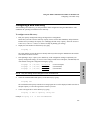
CHAPTER 10. USING THE ARM COMMAND LINE UTILITIES FOR WINDOWS NT ............. 241
ONLINE HELP ........................................................................................................................................... 241
COMMAND SYNTAX CONVENTIONS ......................................................................................................... 242
SELECTING A DISK ARRAY TO MANAGE .................................................................................................. 242
CONFIGURING A NEW DISK ARRAY ......................................................................................................... 243
CHECKING DISK ARRAY STATUS ............................................................................................................. 244
DISPLAYING DISK ARRAY SERIAL NUMBERS ........................................................................................... 245
CHANGING DISK ARRAY CONFIGURATION SETTINGS ............................................................................... 246
MANAGING LOGICAL DRIVES .................................................................................................................. 247
Checking Logical Drive Configuration............................................................................................... 247
Creating a Logical Drive..................................................................................................................... 247
Renumbering a Logical Drive............................................................................................................. 248
Deleting a Logical Drive..................................................................................................................... 248
ADDING A DISK........................................................................................................................................ 249
Including a Disk Manually.................................................................................................................. 250
REBUILDING THE DISK ARRAY................................................................................................................. 251
Rebuilding the Disk Array Manually .................................................................................................. 251
Setting Rebuild Priority ...................................................................................................................... 251
Checking the Progress of a Rebuild .................................................................................................... 252
Canceling a Rebuild............................................................................................................................ 252
ANALYZING DISK ARRAY PERFORMANCE ............................................................................................... 253
Command Examples ........................................................................................................................... 253
PERFORMING DISK ARRAY MAINTENANCE TASKS .................................................................................. 254
Shutting Down the Disk Array............................................................................................................ 254
Restarting the Disk Array.................................................................................................................... 254
Resetting the Disk Array..................................................................................................................... 255
Downing (Excluding) a Disk .............................................................................................................. 255
Testing a Disk ..................................................................................................................................... 256
Displaying Test Results ...................................................................................................................... 256
Canceling a Disk Test ......................................................................................................................... 257
Printing ARMServer Log Contents..................................................................................................... 257
Displaying Hardware Logs ................................................................................................................. 257
Formatting the Disk Array .................................................................................................................. 258
Changing SCSI Settings...................................................................................................................... 259
11
Changing the Controller SCSI ID........................................................................................................ 259
Switching Primary Controllers ............................................................................................................ 259
DOWNLOADING FIRMWARE...................................................................................................................... 260
Downloading Firmware to a Disk Module .......................................................................................... 260
Downloading Firmware to the Disk Array Controllers ....................................................................... 261
Copying Firmware From the Primary Controller to the Secondary Controller ................................... 262
VIEWING THE DISK ARRAY GENERAL CONFIGURATION SETTINGS ........................................................... 263
Simplified Resiliency Setting .............................................................................................................. 269
Setting Data Resiliency ....................................................................................................................... 272
Creating a Disk Array Alias ................................................................................................................ 273
INDEX........................................................................................................................................................ 275
12
HP-UX
Chapter 1. Managing the HP SureStore E
Disk Array 12H on HP-UX
This chapter introduces the tools available for managing your HP SureStore E Disk Array 12H on HP-UX.
These tools provide complete control over all aspects of disk array operation.
The following information is included in this chapter:
•
A brief description of each management tool
•
Which tools can be used for each management task.
•
Instructions for installing the disk array management software
13
HP-UX
Managing the HP SureStore E Disk Array 12H on HP-UX
Disk Array Management Tools
Disk Array Management Tools
Three disk array management tools are available for managing the disk array — two online tools and the
disk array control panel.
System Administration Manager (SAM)
Most of the common tasks involved in managing the disk array can be performed using the HP-UX System
Administration Manager, or SAM. This allows you to manage the host system and the disk array using the
same tool.
AutoRAID Management (ARM) utilities
Included with the disk array is a set of ARM utilities, which provide advanced capabilities for managing the
disk array. Although you will primarily use SAM to manage the disk array, you will need to use the ARM
utilities to perform functions such as formatting or diagnostics.
Disk array control panel
An alternative to the online management tools is the disk array control panel. Although you can use the disk
array control panel to perform most of the management tasks available through the ARM utilities, the added
convenience and functionality provided by SAM and the ARM utilities make them better tools for managing
the disk array.
14
Managing the HP SureStore E Disk Array 12H on HP-UX
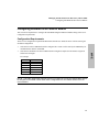
Which Tools to Use for Each Task
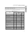
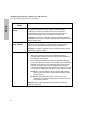
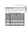
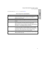
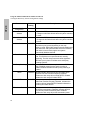
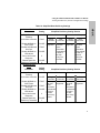
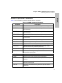
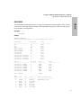
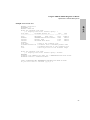
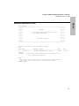
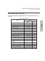
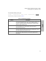
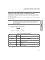
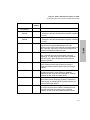
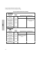
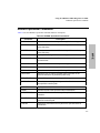
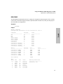
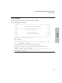
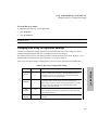
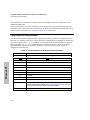
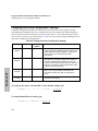
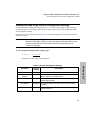
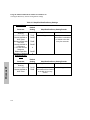
The various management tasks have been divided between SAM and the command- line utilities. In general,
the more common tasks are available from SAM while the more advanced tasks are performed from the
ARM utilities. Most tasks can also be performed using the disk array control panel.
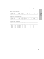
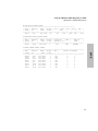
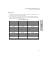
Table 1. Tools and Tasks
Tasks
Tools
SAM
ARM
Utilities
Control
Panel
Including a disk
Yes
Yes (arraycfg)
Yes
Checking disk array status
Yes
Yes (arraydsp)
Yes
Creating/deleting LUNs
Yes
Yes (arraycfg)
Yes
Renumbering LUNs
No
Yes (arraycfg)
Yes
Starting/canceling a Rebuild
No
Yes (arrayrbld)
Yes
Downing (excluding) a disk
Yes
Yes (arraycfg)
No
Formatting a LUN or array
No
Yes (arrayfmt)
Yes
Shutting down the disk array
No
Yes (arraymgr)
Yes
Changing operating settings
Yes
Yes (arraymgr)
Yes
Changing SCSI settings
No
Yes (arraymgr)
Yes
Monitoring performance
No
Yes (arraydsp)
No
Switching primary controller
Yes
Yes (arraymgr)
Yes
Testing a disk
No
Yes (drivetest)
No
Displaying disk test results
No
Yes (dteststat)
No
Displaying disk array serial
numbers
Yes
Yes (arraydsp)
Yes
Changing controller SCSI ID
No
Yes (arraymgr)
Yes
Resetting/restarting the disk array
No
Yes (arraymgr)
Yes
Setting data resiliency
No
Yes (arraymgr)
No
Creating a disk array alias
No
Yes (arraymgr)
No
Recovering data maps
No
Yes (arrayrecover)
Yes
15
HP-UX
Which Tools to Use for Each Task
HP-UX
Managing the HP SureStore E Disk Array 12H on HP-UX
Installing the Disk Array Management Software
Installing the Disk Array Management Software
The AutoRAID Manager (ARM) disk array management software is distributed on the IPR (Independent
Product Release) CD-ROM (B6191AA). The IPR CD-ROM should have been ordered and delivered with
your disk array.
The IPR CD-ROM includes an instruction sheet for installing the software. Follow the instructions to install
the ARM software.
NOTE!
The HP SureStore E Disk Array 12H disk array requires IPR CD-ROM release
IPR9810 or later. Earlier releases of the IPR CD-ROM do not contain the required
software.
At the time of printing the following ARMServer patches were available:
PHCO_15699 for HP-UX 10.X
PHCO_15700 for HP-UX 11.0
The latest patches are available from the HP Patch web site:
(www.hp.com/go/support)
which will indicate if the above patches have been superceded.
Operating System Support
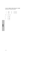
The HP SureStore E Disk Array 12H is currently supported on the following HP-UX releases:
•
•
•
•
10.01
10.10
10.20
11.0
IPR Program
To provide you with the latest software patches and drivers, Hewlett-Packard offers the Independent
Product Release (IPR) program. As a subscriber to this program you will receive a complete collection of
all updated patches and drivers at regular intervals, thus ensuring you always have the latest software. Using
the latest software upgrades will ensure optimal performance of the disk array and other hardware
peripherals.
Contact your Hewlett-Packard sales representative for more details on subscribing to the IPR program.
16
Managing the HP SureStore E Disk Array 12H on HP-UX
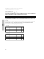
Tips for Configuring the Disk Array On HP-UX
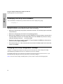
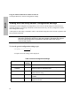
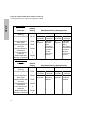
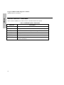
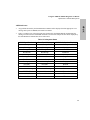
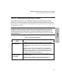
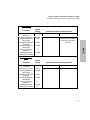
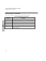
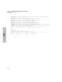
Before installing a new disk array, you should determine what is more important for your operating
environment — performance or capacity. This decision will influence how you configure the disk array
hardware and LVM. There are several configuration options that impact the performance of the disk array.
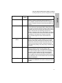
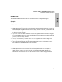
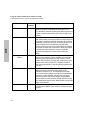
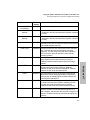
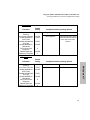
Table 2 identifies the various configuration options, their impact on disk array performance, and any
considerations regarding disk array capacity.
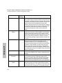
NOTE! Overall system performance is a complex issue influenced by many factors. The
configuration options described here will increase the potential performance of the disk array.
However, the actual performance of the disk array will be determined largely by host demand.
AutoRAID technology is particularly suited to I/O-intensive application environments such as
OLTP and NFS. It is in these environments that the performance benefits offered by AutoRAID
will be fully realized.
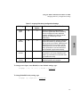
Table 2. Configuration Options
Configuration
Option
Number of LUNs
per disk array
Impact on Performance and Capacity
Performance. Increase the number of LUNs per disk array to improve
performance. More LUNs increases the size of the I/O command queue
allocated by HP-UX, which increases throughput. The recommended
number of LUNs is 4 to 6.
Capacity. To allow for future capacity expansion, avoid creating the
maximum number of LUNs (8) on the disk array. New capacity is made
available through the creation of a new LUN. If the maximum number of
LUNs have already been created, it will be necessary to delete and
recreate an existing LUN to increase capacity.
Number of disk
arrays per SCSI
host adapter
Performance. Limit the number of disk arrays per host adapter to
improve performance. The recommended configuration for maximum
performance is:
NIO adapter - 3 disk arrays
GSC adapter - 8 disk arrays
Capacity. If maximum capacity is more important than performance,
connect the maximum number of disk arrays to each adapter.
17
HP-UX
Tips for Configuring the Disk Array On HP-UX
Managing the HP SureStore E Disk Array 12H on HP-UX
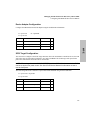
Tips for Configuring the Disk Array On HP-UX
HP-UX
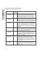
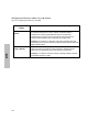
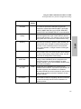
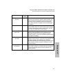
Configuration
Option
Number of disk
drives
Impact on Performance and Capacity
Performance. Increase the number of disk mechanisms in the disk array
for maximum performance. As the number of individual disks is
increased, the number of potential I/Os that can be performed
simultaneously increases as well. This will improve performance in
environments that place heavy I/O demand on the disk array.
Capacity. The capacity of a disk array that is fully populated with disk
mechanisms can only be increased by replacing lower capacity disks with
higher capacity disks.
Unallocated disk
array capacity
Performance. Unallocated capacity is used as additional RAID 0/1
space. The amount of RAID 0/1 space required to maintain optimal
performance is determined by the write working set parameter.
Capacity. To create the maximum amount of storage capacity, allocate
all available capacity to LUNs.
LVM configuration
Performance. To improve performance, configure LVM as follows:
•
Stripe logical volumes across LUNs on different disk arrays.
Including LUNs on different disk arrays will improve throughput by
spreading I/Os across arrays.
•
Divide LUN access between both disk array controllers. Mapping
every LUN to the same controller does not utilize the two data paths
available on the disk array. The default path is through the primary
disk array controller, but this can be changed to the secondary
controller when adding the physical volume to an LVM volume group.
The process for changing the path differs for each version of HP-UX:
HP-UX 10.1. From the Disk Devices list, select the disk hardware
path through the secondary controller before adding the disk to
a volume group.
HP-UX 10.2. When adding the disk to a volume group, in the
“Creating A Volume Group” dialog change the hardware path to
the secondary controller
Capacity. These LVM configurations have no impact on disk array
capacity configuration.
18
HP-UX
Chapter 2. Using the HP-UX System
Administration Manager
Most disk array management can be done using the HP-UX System Administration Manager, or SAM.
Using SAM you can:
•
Check disk array status
•
Change configuration settings
•
Manage the disk array LUNs
•
Add a disk to the array configuration
•
Set the rebuild priority
You must login as superuser or root to use SAM or the disk array utilities.
LUNs and Logical Drives. To maintain consistency with HP-UX terminology, the term LUN is
used to refer to a disk array logical drive. The two terms are used interchangeably and refer to the
same logical entity on the disk array.
NOTE! Before SAM can be used to manage the HP SureStore E Disk Array 12H, the AutoRAID
Manager (ARM) utility software must be installed as described in “Installing the Disk Array
Management Software“.
To run the SAM disk array management utilities:
1.
Run SAM by typing sam at the system prompt.
2.
On the main SAM screen, select “Disks and File Systems.”
3.
On the “Disks and File Systems” screen, select “Disk Devices.” A list of disk devices including arrays
will be displayed.
You are now ready to work with the disk array. The remaining procedures in this chapter assume that you
have already performed these steps.
19
HP-UX
Using the HP-UX System Administration Manager
Selecting Hardware Paths on HP-UX 10.20
Selecting Hardware Paths on HP-UX 10.20
On dual controller disk arrays, each controller provides a separate hardware path to the disk array. The host
identifies one of these paths as the default hardware path and will use the default as the primary data path
for access to the LUNs created on the disk array.
To improve disk array performance, the paths to the LUNs on the disk array should be shared by both
controllers. Dividing the primary data paths across both controllers balances the I/O load and optimizes disk
array performance. The primary hardware path to each LUN is established when adding the LUN to a
volume group.
On HP-UX 10.01 and 10.10, both controller hardware paths are displayed on the Disk Devices windows.
The hardware path for a LUN is established by selecting the appropriate path.
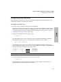
On HP-UX 10.20 and later, only the primary controller hardware path is displayed in the Disk & File
Systems window (with an indication that there are two paths to the device). This makes the selection of an
alternate path to the LUN a bit more involved. The following steps should clarify the process of defining an
alternate path for a LUN.
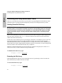
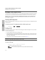
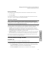
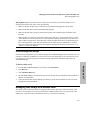
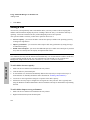
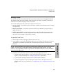
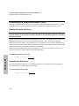
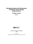
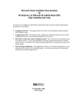
To select an alternate hardware path:
1.
From the Disk & File Systems window select the LUN you want to add.
2.
From the Actions menu select “Add…” , and then select “Using The Logical Volume Manager”.
20
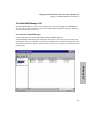
Using the HP-UX System Administration Manager
Selecting Hardware Paths on HP-UX 10.20
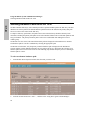
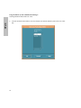
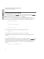
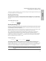
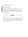
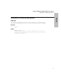
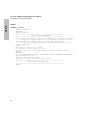
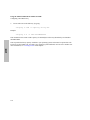
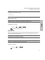
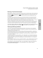
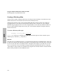
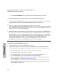
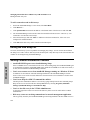
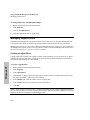
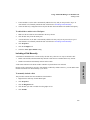
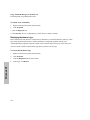
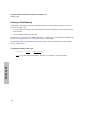
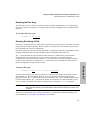
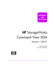
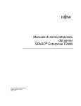
3.
HP-UX
The Create a Volume Group window indicates the default hardware path to the LUN. Click the Use
Hardware Path… button to change the path.
21
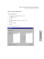
Using the HP-UX System Administration Manager
Selecting Hardware Paths on HP-UX 10.20
HP-UX
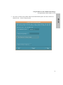
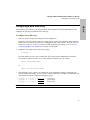
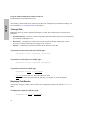
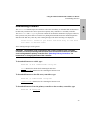
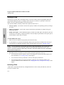
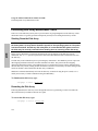
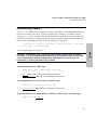
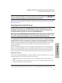
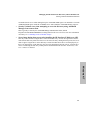
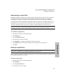
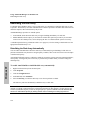
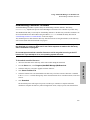
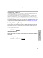
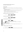
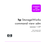
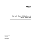
4.
22
From the Alternate Paths window, select the alternate (non-default) hardware path to the LUN. Click
OK.
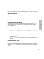
Using the HP-UX System Administration Manager
Configuring a New Disk Array
After installing a new disk array, you can perform the initial configuration using the disk array utilities. This
establishes the desired operating environment for the disk array.
To configure a new disk array:
1.
Plan your capacity management strategy.
Decide how you want to use the capacity of the disk array. Factors such as data redundancy and
performance influence how you manage the capacity. To support your strategy, it may be necessary to
disable Active Hot Spare, Auto Include, or Auto Rebuild. See “Managing Disk Array Capacity” in the
HP SureStore E Disk Array 12H User’s and Service Manual for help in planning your strategy. Also
see “Tips for Configuring the Disk Array On HP-UX” in Chapter 1 of this guide.
2.
If necessary, change disk array configuration settings to implement your capacity management strategy.
If the planning in step 1 requires you to change any of the default configuration settings, do so now.
These include Active Hot Spare, Auto Rebuild, and Auto Include. For more information, see
“Changing Disk Array Configuration Settings” in this chapter.
3.
Check the available unallocated capacity on the disk array. See “Checking Disk Array Status” in this
chapter.
4.
Create each LUN on the disk array.
This required step makes disk array capacity available to your operating system, and it must be
repeated for each LUN you are creating. For more information, see “Creating a LUN” in this chapter.
23
HP-UX
Configuring a New Disk Array
HP-UX
Using the HP-UX System Administration Manager
Checking Disk Array Status
Checking Disk Array Status
One of the most important management tasks is monitoring the operation and status of the disk array.
Because it is a vital piece of your system, it is important to know how well the disk array is operating and if
any problems or failures have occurred.
To view disk array component status:
1.
Select the desired disk array controller from the list displayed on the screen.
2.
Select “Actions” on the menu bar.
3.
Select “View More Information . . .”
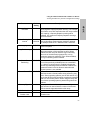
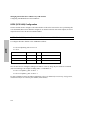
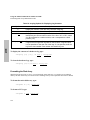
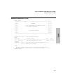
Changing Disk Array Configuration Settings
There are a number of configuration settings that control the operation of the disk array. These settings are
usually established during installation, and once set, should rarely have to be changed.
The default settings have been selected to provide the best operation for most systems. However, if you
determine that any setting does not meet your needs, you can easily change it.
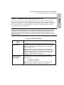
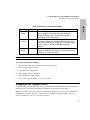
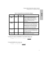
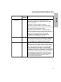
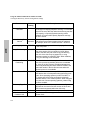
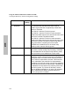
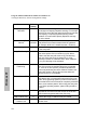
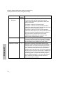
Table 3 lists the various settings that can be changed with SAM, including factors you may want to consider
before changing them.
24
Using the HP-UX System Administration Manager
Managing LUNs (Logical Drives)
HP-UX
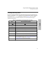
Table 3. Disk Array Configuration Settings
Setting
Default
Comments and Considerations
Active
Spare
On
Rebuild
Priority
High
Rebuild Priority determines how quickly a Rebuild
completes. It allows you to balance the servicing of host
I/Os with the rebuilding of the disk array. The same rebuild
priority is used for both Auto Rebuilds and manual
Rebuilds.
Auto
Include
On
Auto Include simplifies the task of adding a new disk to
your array. Disabling it will require you to manually include
each disk you install in the array.
Active Spare provides optimum protection against disk
failure. Disabling Active Spare will make additional
capacity available to the host, but at the expense of
maintaining full data redundancy.
NOTE! The Rebuild type (automatic or manual) is displayed but cannot be changed using SAM.
To change configuration settings:
1.
Select the desired disk array controller from the list on the screen.
2.
Select “Actions” on the menu bar.
3.
Select “Disk Array Maintenance.”
4.
Select “Modify Array Configuration . . .”
5.
Click setting boxes to make changes.
6.
Click “OK” to effect the change, or “Cancel” to ignore.
Managing LUNs (Logical Drives)
An important part of managing the disk array involves defining and maintaining the optimal LUN structure
for the disk array. Your system requirements will influence the LUN structure you choose.
Managing LUNs is a part of the overall task of managing the disk array capacity. For more information on
managing array capacity to meet your system needs, see “Managing Disk Array Capacity” in the HP
SureStore E Disk Array 12H User’s and Service Manual.
25
Using the HP-UX System Administration Manager
Managing LUNs (Logical Drives)
HP-UX
Checking LUN Configuration
Anytime you are managing LUNs, you may find it convenient to check the current LUN configuration and
the available capacity.
The current LUN definitions can be seen on the standard “Disk Devices” screen. The available capacity is
displayed as “Unallocated” on the “View Array Status Information” screen. See “Checking Disk Array
Status” in this chapter.
Creating a LUN
Only capacity assigned to LUNs is visible to the HP-UX operating system. When creating LUNs, consider
the following factors:
•
Any size limitations imposed by the operating system, for example, LVM.
•
Your backup strategy. If you do unattended backup to a device such as tape, you may want to avoid
creating a LUN that is larger than the capacity of the media. This allows you to backup an entire LUN
without changing media.
•
Configuring the LUN into LVM for maximum performance as described in Table 2.
NOTE! Before creating a LUN, check your operating system documentation for any additional
information or steps that may be required to create a LUN.
To create a LUN:
1.
Select the desired disk array controller from the list on the screen.
2.
Select “Actions” on the menu bar.
3.
Select “Disk Array Maintenance.”
4.
Select “Bind LUN . . .”
5.
Set the LUN size (not greater than unallocated capacity).
6.
Select “OK.”
7.
Note the new LUN definition in the list of disks and arrays.
26
Using the HP-UX System Administration Manager
Managing LUNs (Logical Drives)
HP-UX
Deleting a LUN
CAUTION! All data on a LUN is lost when it is deleted. Make sure you backup any
important data on the LUN before deleting it.
When a LUN is deleted, its capacity is returned to the pool of unallocated capacity. Deleting a LUN is a
good way of freeing up capacity for the Active Hot Spare or for RAID 0/1 space to improve disk array
performance.
NOTE! Before deleting a LUN, check your operating system documentation for any additional
information or steps that may be required to delete a LUN.
To delete a LUN:
1.
From the list of disks and arrays, select the LUN to be deleted.
2.
Select “Actions” from the menu bar.
3.
Select “Disk Array Maintenance.”
4.
Select “Unbind LUN...”
5.
Select “OK” to confirm the request.
6.
Note the removal of the LUN from the list of disks and arrays.
27
HP-UX
Using the HP-UX System Administration Manager
Adding a Disk
Adding a Disk
At some time you will probably want to add another disk to your array. Features such as hot-pluggable disks
and Auto Include simplify the process of adding a disk to the array even while it is operating. A disk can be
added to the array without disrupting host operation.
After you have added a new disk, you have three options on how to use it:
•
Increase capacity - you can use the disk to increase the capacity available to the operating system by
creating a new LUN.
•
Improve performance - you can use the disk to improve disk array performance by simply leaving it as
unallocated capacity.
•
Enable Active Spare - you can use the additional capacity to enable Active Spare if the disk array does
not currently have the capacity to implement this feature.
To add a disk to the array:
1.
Make sure the new disk has been inserted into the array cabinet.
2.
If Auto Include is on, the disk is automatically added to the array and you can skip to the next step. If
Auto Include is off, manually include the disk as described in the next section, “Including a Disk.”
NOTE! In some situations, the array will not include a disk automatically, even if Auto Include is
enabled. This will happen if the new disk’s status is not Normal. See “Auto Include” in the HP
SureStore E Disk Array 12H User’s and Service Manual for more information about when this
might occur.
3.
28
Depending on how the new disk will be used, perform the appropriate next step:
•
To use the disk to increase capacity, create a LUN using all or a portion of the disk capacity. For
more information, see “Creating a LUN” in this chapter.
•
To use the disk to increase performance, leave the disk capacity unallocated.
•
To use the disk capacity for Active Spare, enable the Active Spare feature if disabled.
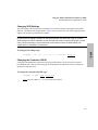
Using the HP-UX System Administration Manager
Adding a Disk
A disk must be included in the disk array configuration before it can be used by the disk array. There are
two ways to include a disk:
•
You can enable Auto Include, which will automatically include a disk when it is inserted into the disk
array enclosure.
•
You can manually include each new disk.
For convenience, Auto Include is enabled by default on a new disk array. For information on disabling Auto
Include, see “Changing Disk Array Configuration Settings” in this chapter.
After including a disk, you must decide how you want to use it. For more information, see the preceding
section, “Adding a Disk.”
To manually include a disk:
1.
Select the desired disk array controller from the list on the screen.
2.
Select “Actions” on the menu bar.
3.
Select “Disk Array Maintenance.”
4.
Select “Include Disk . . .”
Disks not currently included will be highlighted on the display.
5.
Select one of the highlighted disks to include.
6.
Click “OK” to effect the change.
29
HP-UX
Including a Disk
HP-UX
Using the HP-UX System Administration Manager
Adding a Disk
Downing (Excluding) a Disk
Downing (or excluding) a disk is typically done in preparation for testing the disk. After the disk is downed,
testing can be done without impacting disk array operation. If testing reveals that the disk is good, the disk
can be included back in the array configuration.
Downing a disk has the same effect as if the disk failed or was physically removed from the cabinet. If Auto
Rebuild is enabled, the disk array will immediately begin a Rebuild when a disk is downed.
The down operation can be either destructive or nondestructive. The type of down performed determines
whether the disk array will assume there is any valid data on the disk if it is returned to the array
configuration. If a destructive down is performed, the disk array will assume no data on the disk is valid. If
the down is nondestructive, the disk array will assume any data on the disk that was not updated in the
disk’s absence is valid.
To protect data availability, the disk array will normally not let you down a disk if doing so would result in
loss of data redundancy or data unavailability. However, you can override this protection by specifying the
appropriate Exclusion Restriction. You can choose to down the disk even if a loss of redundancy would
result, but not data unavailability. Or you can down the disk even if data unavailability would occur.
NOTE.
Two disks on the disk array are used to store the information for recovering data
maps if they are lost. The disk array will not let you down one of these RDM disks.
To down a disk:
1.
Select the desired disk array controller from the list on the screen.
2.
Select “Actions” on the menu bar.
3.
Select “Disk Array Maintenance.”
4.
Select "Exclude Disk...”
5.
Select the disk to exclude.
6.
Select the desired "Exclusion Restriction".
7.
Select "Assume Valid Data Next Time" to make the exclude nondestructive. If this option is not
selected, the exclude will be destructive.
8.
Click “OK” to effect the change, or click "Apply" to select another disk to exclude.
After testing, a downed disk can be returned to the disk array configuration by manually including it. For
more information, see the preceding section, “Including a Disk”.
30
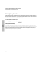
Using the HP-UX System Administration Manager
Rebuilding the Disk Array
HP-UX
Rebuilding the Disk Array
To maintain data redundancy in the event of a disk failure, it is important to rebuild the disk array as
quickly as possible. The Auto Rebuild feature does this automatically, so it is enabled by default. For
optimum data protection it recommended that Auto Rebuild remain enabled.
If you would like more control over the Rebuild process, you can disable Auto Rebuild using the ARM
utilities. This will allow you to manually start a Rebuild at the time you choose. A manual Rebuild is
initiated using the ARM utilities. See “Rebuilding the Disk Array Manually” in the next chapter for more
information.
A Rebuild impacts disk array performance while it is in progress, so before starting a Rebuild make sure the
appropriate rebuild priority is set.
For convenience and maximum protection against disk failure, Auto Rebuild is enabled by default on a new
disk array.
Setting Rebuild Priority
The rebuild priority determines how quickly a Rebuild completes. It allows you to balance the servicing of
host I/Os with the rebuilding of the disk array. The same rebuild priority is used for both Auto Rebuilds and
manual Rebuilds. A high rebuild priority ensures the Rebuild will be completed at the same priorities as
host I/Os. A low rebuild priority gives priority to host I/Os in relation to the Rebuild.
To ensure that a Rebuild completes without disrupting data storage, the rebuild priority is set to high by
default on new disk arrays.
To set the rebuild priority:
1.
Select the desired disk array controller from the list.
2.
Select “Actions” on the menu bar.
3.
Select “Disk Array Maintenance.”
4.
Select “Modify Array Configuration . . .”
5.
Select desired rebuild priority (high or low).
6.
Select “OK” to effect the change.
31
HP-UX
Using the HP-UX System Administration Manager
Switching Primary Controllers
Switching Primary Controllers
In dual-controller disk array configurations, the array automatically switches to the secondary controller if
the primary controller fails. However, you can switch controllers manually if necessary. This will cause the
secondary controller to assume the role of primary controller.
To switch primary controllers:
1.
Select the desired disk array controller from the list.
2.
Select “Actions” on the menu bar.
3.
Select “Disk Array Maintenance.”
4.
Select “Modify Array Configuration . . .”
5.
Select desired primary controller.
6.
Select “OK” to effect the change.
32
HP-UX
Chapter 3. Using the ARM Command Line
Utilities for HP-UX
The AutoRAID software includes a set of AutoRAID Manager (ARM) command line utilities. These
commands provide the ability to manage the disk array from the HP-UX command prompt rather than from
SAM.
The ARM commands can be used to perform a number of tasks that cannot be performed using SAM.
These tasks are intended for advanced users and involve procedures such as diagnostics, performance
monitoring, setting SCSI values, and disk array maintenance.
CAUTION! Many of the tasks available in SAM can also be performed using the ARM
utilities. These tasks are described on the following pages. It is recommended that these
tasks be performed using SAM to ensure predictable results and proper operation of the
disk array. You should consider using an ARM utility for these tasks only if you clearly
understand how the utility works and what effect it has on disk array operation. Improper
use of the ARM utilities can cause undesirable results, including loss of data.
LUNs and Logical Drives. To maintain consistency with HP-UX terminology, the term LUN is
used to refer to a disk array logical drive. The two terms are used interchangeably and refer to the
same logical entity on the disk array.
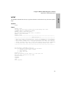
Information in man pages
The procedures in this chapter summarize the use of the ARM utilities. Detailed information about the
ARM command line utilities and their proper usage is included in the HP-UX operating system man pages.
A man page also exists for ARMServer, the server portion of the disk array management software.
To access HP-UX man pages information, type:
man <commandname>
Substitute one of the following ARM utility names for commandname.
ARMServer
arraycfg
arraydsp
33
Using the ARM Command Line Utilities for HP-UX
Command Syntax Conventions
HP-UX
arrayfmt
arraylog
arraymgr
arrayrbld
arrayrecover
download
drivetest
dteststat
logprint
Command Syntax Conventions
The following symbols are used in the command descriptions and examples:
Symbol
<>
|
[]
{}
Meaning
Integer value, whose units are not defined.
“Exclusive OR.” Exactly one of the
parameters displayed will be used.
Items enclosed are optional.
Items enclosed are required.
The ARMServer Process
The ARMServer process is the server portion of the ARM software. It monitors the operation and
performance of the disk array, and services external requests from clients executing disk array commands.
The ARMServer process monitors disk array performance and status, maintains disk array logs, initiates
diagnostics, and allows clients to examine and change the disk array configuration.
The ARMServer process must be running to allow management of the disk array using the ARM command
line utilities. Because of its importance in managing the disk arrays, the ARMServer process is launched
automatically when the system is booted. Host I/Os to the disk array are not dependent on the ARMServer
process and are serviced regardless of whether the ARMServer process is running or not.
34
Using the ARM Command Line Utilities for HP-UX
The Array Monitor Daemon (arraymond)
The Array Monitor Daemon, known as the arraymond process, runs at regular intervals (every fifteen
minutes) to retrieve disk array status information. The arraymond process uses the arraydsp ARM utility,
and therefore requires the ARMServer process to be running. By retrieving status from the disk array at
regular intervals, arraymond can alert the system operator to any array problems.
The arraymond process is included with the ARM software and is installed with the other software
components. Like ARMServer, the arraymond process is launched automatically when the system is
booted.
Routing arraymond Error Messages
By default, the status messages generated by arraymond are sent to the system console and emailed to
root. The destination for the error messages can be rerouted by editing the contents of the destination
configuration file, etc/hpC2400/arraymon.dest. This file identifies the destinations for all error
messages.
The first line in the file identifies a computer screen (/dev/console) or none (/dev/null), if no
screen messages are desired. The rest of the file identifies electronic mail addresses.
The following example of an arraymon.dest file directs the arraymond process to send its error
messages to the system console and to also mail the messages to three people on other systems.
/dev/console
root
bob@hpdml69
alex@hpdmm99
35
HP-UX
The Array Monitor Daemon (arraymond)
HP-UX
Using the ARM Command Line Utilities for HP-UX
Selecting a Disk Array to Manage
Selecting a Disk Array to Manage
When using the ARM utilities, the <array-id> field is used to identify the disk array. The <arrayid> field can contain the disk array serial number, the raw device file name of any LUN on the array, or an
alias text string assigned to the array using the arraymgr command.
For example, assume a disk array has a serial number of 00786B5C0000, special raw device file
/dev/rdsk/c2t0d0 is defined for this array, and it has an alias of autoraid4. To check the available
unallocated capacity on this particular disk array, you could use any of the following commands:
arraydsp 00786B5C0000
or
arraydsp /dev/rdsk/c2t0d0
or
arraydsp autoraid4
The serial number of all arrays in the system can be obtained using the command
arraydsp -i
For more information see "Displaying Disk Array Serial Numbers" in this chapter.
A list of all special device filenames assigned to the disk array can be displayed using the following
command:
ioscan -fn -C disk
Many commands affect the operation of the entire disk array, regardless of whether the <array-id> field
contains the array serial number or a special device file name. Commands that involve only a specific LUN
on the array will include an option (-L LUN) for identifying the LUN involved. For example, to format
LUN 3 on a disk array that is referenced by /dev/rdsk/c2t0d0, you would use the following
command:
arrayfmt -L 3 /dev/rdsk/c2t0d0
36
Using the ARM Command Line Utilities for HP-UX
Configuring a New Disk Array
HP-UX
Configuring a New Disk Array
After installing a new disk array, you can perform the initial configuration using the ARM utilities. This
establishes the operating environment for the disk array.
To configure a new disk array:
1.
Plan your capacity management strategy and LUN configuration.
Decide how you want to use the disk array capacity. Factors such as data redundancy and performance
influence how you manage the capacity. See “Managing the Disk Array Capacity” in the HP SureStore
E Disk Array 12H User’s and Service Manual for help in planning your strategy. Also see “Tips for
Configuring the Disk Array On HP-UX” in Chapter 1 of this guide.
2.
Display the serial number of the disk array by typing:
arraydsp -i
The serial number provides a way to identify disk arrays when using the ARM utilities. Record the
serial number for future reference, or set a shell variable to hold this value, for example:
export ID=00786B5C0000
or
export ID=/dev/rdsk/c2t0d0
3.
If the planning in step 1 requires you to disable any of the configuration settings to implement your
capacity management strategy, do so now. These settings include Active Hot Spare, Auto Rebuild, and
Auto Include. Change the configuration settings by typing:
arraymgr -h { on|off } <array-id>
arraymgr -a { on|off } <array-id>
arraymgr -i { on|off } <array-id>
(Active Spare)
(Auto Rebuild)
(Auto Include)
NOTE! Only one setting can be changed on each command line.
37
Using the ARM Command Line Utilities for HP-UX
Configuring a New Disk Array
HP-UX
4.
Check the available unallocated capacity on the disk array by typing:
arraydsp $ID
The total unallocated capacity available for creating LUNs will be displayed. Make sure there is
adequate capacity to create the LUN structure you need.
5.
Create each LUN on the disk array by typing:
arraycfg -L LUN -a capacity <array-id>
Example:
arraycfg -L 0 -a 1000 00786B5C0000
This command creates LUN 0 with a capacity of 1000 Mbytes on the array identified by serial number
00786B5C0000.
This step makes disk array capacity available to your operating system, and it must be repeated for each
LUN to be created. Make sure you observe any operating system limitations on LUN size or number. For
more information, see “Creating a LUN” in this chapter.
38
Using the ARM Command Line Utilities for HP-UX
Checking Disk Array Status
One of the most important management tasks is monitoring the status, operation, and configuration of the
disk array. It is important to know how well the disk array is operating and if any problems or failures have
occurred. Using the ARM arraydsp command, you can easily check all aspects of disk array operation
and configuration. The arraydsp command options, summarized in Table 4, allow you to display
information about each disk array hardware component, as well as information about the logical
configuration of the disk array.
Table 4. arraydsp Options for Displaying Disk Array Status
Option
none
-l [LUN]
Status Information Displayed
General information about the disk array
Information for the specified LUN
-a
All information displayed for options -l, -d, -c, -s, -v, and -h
-c
Array controller status
-d
Disk status
-h
Hardware status
-i
Serial numbers for all disk arrays
-m
Display performance metrics
-R
Rescan for SureStore E (AutoRAID) disk arrays recognized by the
host.
-r
Make performance recommendations
-S
Generate raw output, used in combination with other options
-s
General configuration information. For a complete description of
all the configuration settings, see “Viewing the Disk Array General
Configuration Settings” at the end of this chapter.
-v
Capacity information
39
HP-UX
Checking Disk Array Status
HP-UX
Using the ARM Command Line Utilities for HP-UX
Displaying Disk Array Serial Numbers
Displaying Disk Array Serial Numbers
The serial numbers of all disk arrays connected to the host can be displayed by typing:
arraydsp -i
Missing Disk Arrays? If you know there are disk arrays connected to the host but they are not
displayed in response to the arraydsp command, check the following:
•
Make sure all disk arrays are properly connected to the host. This includes proper termination
of the SCSI bus.
•
Make sure all disk arrays are turned on and operating properly.
•
Make sure the ARMServer process is running. ARMServer must be running to execute this or
any other ARM command. You can easily check to see if the ARMServer process is running
using the following command: -ps ef | grep ARM
•
Rescan for disk arrays by typing: arraydsp -R. This will update the ARMServer information to
reflect the current system configuration.
•
Execute the ioscan -fn -C disk command and ensure that the software state for all active disk
arrays is "CLAIMED".
Changing Disk Array Configuration Settings
A number of configuration settings control the operation of the disk array. These settings are usually
established during installation and once set, should rarely need to be changed.
The default settings have been selected to provide the best operation for most systems. However, if you
determine that any setting does not meet your needs, you can easily change it.
Table 5 lists the various settings, including factors you may want to consider when changing them.
40
Using the ARM Command Line Utilities for HP-UX
Changing Disk Array Configuration Settings
HP-UX
Table 5. arraymgr Disk Array Configuration Settings
Setting
Default
Command
Option
Comments and Considerations
Active
Spare
On
-h
Active Hot Spare provides optimum
protection against disk failure. Disabling
Active Hot Spare will make additional
capacity available to the host, but at the
expense of maintaining full data
redundancy.
Auto
Rebuild
On
-a
Auto Rebuild provides optimum protection
against disk failure by rebuilding a failed
disk as quickly as possible. Disabling Auto
Rebuild gives you more control over the
rebuild process, but it can leave the disk
array vulnerable to a second disk failure
until a Rebuild is performed manually.
Auto
Include
On
-i
Auto Include simplifies the task of adding
a new disk to your array. Disabling it will
require you manually to include each disk
you install in the array.
Rebuild
Priority
High
-p
Rebuild priority determines how quickly a
Rebuild operation will complete.
To change Active Spare, Auto Rebuild, or Auto Include settings, type:
arraymgr { -h | -a | -i } { on|off } <array-id>
To change Rebuild Priority setting, type:
arraymgr -p { high|low } <array-id>
41
HP-UX
Using the ARM Command Line Utilities for HP-UX
Managing LUNs (Logical Drives)
Managing LUNs (Logical Drives)
An important part of managing the disk array involves defining and maintaining the optimal LUN structure
for your system. Your system requirements and limitations will influence the LUN structure you choose.
Managing LUNs is a part of the overall task of managing disk array capacity. For more information on
managing disk array capacity to meet your system needs, refer to the HP SureStore E Disk Array 12H
User’s and Service Manual.
Checking LUN Configuration
When you are managing LUNs, you may find it convenient to check the current LUN configuration and the
available capacity.
To check the current LUN configuration and the available capacity, type:
arraydsp -l [LUN] <array-id>
Creating a LUN
Only capacity assigned to LUNs is visible to the operating system. When selecting the size for your LUNs,
consider the following factors:
•
Any size limitations imposed by the operating system, for example, LVM.
•
Your backup strategy. If you do unattended backup to a device such as a tape, you may want to avoid
creating a LUN that is larger than the capacity of the tape media. This allows you to back up an entire
LUN without changing tapes.
•
Configuring the LUN into LVM for maximum performance as described in Table 2.
NOTE! Before creating a LUN, check your operating system documentation for any additional
information or steps that may be required to create a LUN.
To create a LUN, type:
arraycfg -L LUN -a capacity <array-id>
LUN must be an unused value between 0 and 7
Capacity must be less than or equal to the currently available unallocated capacity
42
Using the ARM Command Line Utilities for HP-UX
Managing LUNs (Logical Drives)
HP-UX
NOTE! The following commands require LUN exclusive access. This means nothing, including
LVM, can access the LUN while the command is running. If LVM is used, the volume group
containing the LUN must be deactivated for the command to run.
Delete LUN
Format LUN
Renumber LUN
Renumbering a LUN
NOTE! Before renumbering a LUN, check your operating system documentation for any
additional information or steps that may be required to renumber a LUN.
To renumber a LUN, type:
arraycfg -L LUN -r newLUN <array-id>
LUN is the LUN to be renumbered
newLUN is a new available LUN number
Deleting a LUN
When a LUN is deleted, its capacity is returned to the pool of unallocated capacity space. Deleting a LUN
is a good way of freeing up capacity for the Active Hot Spare or for simply adding more unallocated
capacity to improve disk array performance.
CAUTION! All data on a LUN is lost when it is deleted. Make sure you backup any
important data on the LUN before deleting it.
NOTE! Before deleting a LUN, check your operating system documentation for any additional
information or steps that may be required to delete a LUN.
43
Using the ARM Command Line Utilities for HP-UX
Adding a Disk
HP-UX
To delete a LUN, type:
arraycfg -L LUN -d <array-id>
LUN is the LUN to be deleted
Adding a Disk
At some time, you may want to add another disk to your array. Features such as hot-pluggable disks and
Auto Include simplify the process of adding a disk to the array even while it is operating. A disk can be
added to the array without disrupting current I/O operations.
After you have added a new disk, you have three options on how to use it:
•
Increase capacity - use the disk to increase the capacity available to the operating system by creating a
new LUN.
•
Improve performance - use the disk to improve the disk array performance by simply leaving it as
unallocated capacity.
•
Enable Active Spare - use the additional capacity to enable Active Hot Spare if the disk array does not
currently have the capacity to support this feature. This also improves performance as the spare space is
used as RAID 0/1 space until it is needed.
To add a disk to the array:
1.
Make sure the new disk has been physically inserted into the array.
2.
If Auto Include is on, the disk is automatically added to the array and you can skip to the next step. If
Auto Include is off, manually include the disk as described in the next section, “Including a Disk.”
NOTE! In some situations, the array will not include a disk automatically, even if Auto Include is
enabled. This will occur if the new disk’s status is something other than Normal. See “Auto
Include” in the HP SureStore E Disk Array 12H User’s and Service Manual for more information
about when this might occur.
3.
44
Depending on how you intend to use the new disk, perform the appropriate next step:
•
To use the disk to increase capacity, create a LUN using all or a portion of the disk capacity. For
more information, see “Creating a LUN” in this chapter.
•
To use the disk to increase performance, leave the disk capacity unallocated.
Using the ARM Command Line Utilities for HP-UX
Adding a Disk
•
Including a Disk
A disk must be included in the disk array configuration before it can be used by the disk array. There are
two ways to include a disk:
•
You can enable Auto Include, which will automatically include a disk when it is inserted into the disk
array enclosure.
•
You can manually include each new disk.
For convenience, Auto Include is enabled by default on a new disk array. For information on disabling Auto
Include, see “Changing Disk Array Configuration Settings” in this chapter.
After including a disk, you must decide how you want to use it. For more information, see the preceding
section, “Adding a Disk.”
To manually include a disk, type:
arraycfg -D slot -a <array-id>
slot is the cabinet shelf containing the disk drive (A1 through A6, or B1 through B6)
45
HP-UX
To use the disk capacity for an Active Hot Spare, enable the Active Hot Spare feature if not
currently enabled. For more information, see “Changing Disk Array Configuration Settings” in this
chapter.
HP-UX
Using the ARM Command Line Utilities for HP-UX
Rebuilding the Disk Array
Rebuilding the Disk Array
To maintain data redundancy in the event of a disk failure, it is important to rebuild the disk array as
quickly as possible. Auto Rebuild does this automatically, and it is enabled by default. For optimum data
protection it recommended that Auto Rebuild remain enabled.
If you want more control over the Rebuild process, you can disable Auto Rebuild. This will allow you to
manually start a Rebuild at the time you choose. A Rebuild impacts disk array performance while it is in
progress, so before starting a Rebuild make sure the appropriate Rebuild Priority is set. See “Setting
Rebuild Priority” in this chapter.
For convenience and maximum protection in the event of a disk failure, Auto Rebuild is enabled by default
on a new disk array. For information on disabling Auto Rebuild, see “Changing Disk Array Configuration
Settings” in this chapter.
Rebuilding the Disk Array Manually
If you have chosen to disable Auto Rebuild, you will have to start the Rebuild manually. The Rebuild will
begin immediately and continue to completion. If no Rebuild is necessary, the command will be ignored.
To start a Rebuild manually, type:
arrayrbld -r <array-id>
Setting Rebuild Priority
The rebuild priority determines how quickly a Rebuild completes. It allows you to balance the servicing of
host I/Os with the rebuilding of the disk array. The same rebuild priority is used for both Auto Rebuilds and
manual Rebuilds.
To set the rebuild priority, type:
arrayrbld -P { high|low } <array-id>
46
Using the ARM Command Line Utilities for HP-UX
Rebuilding the Disk Array
Checking the Progress of a Rebuild
HP-UX
You can easily check the progress of a Rebuild. This allows you to determine approximately when a
Rebuild will complete.
To check the progress of a Rebuild, type:
arrayrbld -p <array-id>
Canceling a Rebuild
A Rebuild can be canceled only if it was started manually. A Rebuild that was started by Auto Rebuild
cannot be canceled. If a Rebuild is canceled, it must be started over again and any progress made during the
first Rebuild will be lost.
When canceling a Rebuild, the Rebuild may not stop immediately. This occurs if the disk array is busy
servicing higher priority I/O requests from the host. The Rebuild will be canceled when the disk array has
serviced all higher priority commands.
To cancel a manual Rebuild, type:
arrayrbld -c <array-id>
47
HP-UX
Using the ARM Command Line Utilities for HP-UX
Analyzing Disk Array Performance
Analyzing Disk Array Performance
The disk array monitors and stores a number of metrics that reflect how the disk array is performing. The
disk array management software periodically retrieves these performance metrics and stores them for your
viewing. The ARM software can also analyze the performance metrics to identify any potential performance
problems. Based on this analysis, recommendations are made on how to improve disk array performance.
Checking the metrics regularly is a quick and easy way for you to monitor the performance of the disk array
and identify any problems that may be developing. You may choose to display only the recommendations,
or you may want to view the metrics for further analysis.
For a complete description of each performance metric, refer to the HP SureStore E Disk Array 12H User’s
and Service Manual. You can also view the arraydsp man page for a complete explanation of all the
performance command options.
To analyze disk array performance, type:
arraydsp { -r stime etime} | { -m stime etime [int] } <array-id>
Command Examples
The following command displays performance recommendations for disk array serial number
00786B5C0000. Performance is analyzed for the time period starting at 8:00 AM and ending at 5:00 PM
(1700) on March 15. The format of the stime and etime arguments is mmddhhmm[yy].
arraydsp -r 03150800 03151700 00786B5C0000
The following command displays the performance metrics for disk array serial number 00786B5C0000.
Metrics are displayed for the time period starting at 11:00 AM and ending at 6:00 PM on April 6. A display
interval of 30 minutes is specified.
arraydsp -m 04061100 04061800 2 00786B5C0000
48
Using the ARM Command Line Utilities for HP-UX
Analyzing Disk Array Performance
When analyzing performance, you must define the time period over which the analysis will be performed. A
starting time (stime) and ending time (etime) establish the analysis period. For the best results, select a
time period when performance may be a concern. This will produce the most meaningful analysis and
recommendations.
For example, if the heaviest load on the disk array occurs between the hours of 8:00 AM and 5:00 PM,
restrict the analysis to this time period. If you include periods of less activity, the analysis may yield
different results and consequently different recommendations. This occurs because activity is averaged over
the entire analysis period, and periods of less activity will offset the effects of busier periods.
Typically, you should select a period of time that represents normal system operation. Avoid any unusual
events such as a Rebuild or changes made to array capacity. If you select a time period that includes an
event that may distort the analysis, the utility will alert you and will not provide any recommendations.
You can also control the display interval using the int option. This allows you to control how much detail
you get when displaying the metrics. The display interval is the number of 15-minute increments.
Checking the Working Set Metric
A key factor in monitoring and maintaining optimal performance of the disk array is the Working Set
metric. To ensure that disk array performance is maintained, you should access the performance metrics
regularly and check the Working Set value.
The Working Set performance metric is derived from the Write Working Set parameter. It indicates the
ratio of the Write Working Set size to the amount of RAID 0/1 space available. For a detailed explanation
of the Write Working Set and its impact on performance, refer to the HP SureStore E Disk Array 12H
User’s and Service Manual.
To maintain performance, the amount of RAID 0/1 space should equal or exceed the Write Working Set,
resulting in a Working Set value less than or equal to 1. A Working Set value greater than 1 indicates that
the Write Working Set is larger than the available RAID 0/1 space and the disk array is servicing writes
from RAID 5 space.
If the Working Set consistently exceeds 1, the amount of RAID 0 /1 space available should be increased to
improve performance. This can be accomplished in several ways as described in the following section.
If the Working Set is consistently much less than 1, some of the RAID 0/1 capacity can be allocated to a
new LUN without impacting performance. The remaining RAID 0/1 space should be adequate to
accommodate the Write Working Set.
49
HP-UX
Selecting a Time Period for Analysis
HP-UX
Using the ARM Command Line Utilities for HP-UX
Performing Disk Array Maintenance Tasks
Performing Disk Array Maintenance Tasks
There are several tasks that you may have to perform in the on-going management of the disk array. These
maintenance tasks are typically performed infrequently and may involve taking the disk array off line.
Shutting Down the Disk Array
CAUTION! When an array shutdown is performed, the disk array becomes unavailable to
the host system. An array that is shutdown appears to the operating system as if its power
has been turned off. As with any disk subsystem, it is essential that file system and LVM
access to the disk array be correctly removed before shutting down or powering off the
disk array.
Before an array Shutdown is performed, all mounted file systems and LVM logical volumes mapped to the
disk array must be unmounted. The umount operation synchronizes data in the HP-UX internal buffers
with the data stored on the disk array.
The disk array must be Shutdown prior to performing any maintenance. The Shutdown process copies vital
data mapping information from the controller NVRAM to the disks. This protects the data mapping
information should the contents of the NVRAM be lost or corrupted due to battery failure. Shutdown then
takes the disk array off line, making all data unavailable to the host. The disk array can still be managed and
tested, but all data is inaccessible while the disk array is Shutdown.
Shutdown is initiated automatically each time the disk array is turned off using the power switch, so it is
usually not necessary to initiate a Shutdown using the ARM utility.
To Shutdown the disk array, type:
arraymgr -s shut <array-id>
Restarting the Disk Array
Following Shutdown, the disk array can be brought back on line by performing a restart. This makes the
data on the disk array available to the host once again.
To restart the disk array, type:
arraymgr -s start <array-id>
50
Using the ARM Command Line Utilities for HP-UX
Performing Disk Array Maintenance Tasks
Resetting the Disk Array
The disk array can be reset if there is a problem with SCSI channel communication. A reset will interrupt
access to the disk array temporarily, so it should be done only when attempting to solve a problem with the
disk array.
To reset the disk array, type:
arraymgr -R <array-id>
Downing (Excluding) a Disk
Downing (or excluding) a disk is typically done in preparation for testing the disk. After the disk is downed,
testing can be done without impacting disk array operation. If testing reveals that the disk is good, the disk
can be included back in the array configuration.
Downing a disk has the same effect as if the disk failed or was physically removed from the cabinet. If Auto
Rebuild is enabled, the disk array will immediately begin a Rebuild when a disk is downed.
The -v option identifies the down operation as either destructive or nondestructive. This determines
whether the disk array will assume there is any valid data on the disk if it is returned to the array
configuration. If a destructive down is performed (-v not specified), the disk array will assume no data on
the disk is valid. If the down is nondestructive (-v specified), the array will assume any data on the disk
that was not updated in the disk’s absence is valid.
To down a disk, type:
arraycfg -D slot -d [-v] [-R|-Z] <array-id>
To protect data availability, the disk array will not let you down a disk if doing so would result in loss of
data redundancy or data unavailability. However, you can override this protection by specifying the
appropriate ARM options. The -R option allows the disk to be downed even if a loss of redundancy would
result, but not data unavailability. The -Z option allows the disk to be downed even if data unavailability
would occur. A complete description of the options is included in the arraycfg man page.
NOTE.
Two of the disks in the disk array are used to store recovery map information. The
disk array will not allow you to down either of these drives unless you use the -R or
-Z option.
51
HP-UX
After the array completes initialization, file system and LVM logical volumes mapped to the disk array must
be mounted for HP-UX to access the disk array.
HP-UX
Using the ARM Command Line Utilities for HP-UX
Performing Disk Array Maintenance Tasks
After testing, a downed disk can be returned to the disk array configuration by manually including it. For
more information, see “Including a Disk” in this chapter.
Testing a Disk
Diagnostics allow you test the operation and integrity of a disk. Three different types of testing can be
performed:
•
Write/Read/Verify - a destructive test that will destroy data on the disk being tested. The disk must be
downed before beginning the test.
•
Read/Verify - a nondestructive test that will not alter any data on the disk being tested. It is not
necessary to down the disk before performing a read/ verify test.
•
Self-test - a nondestructive internal test that checks the operation of the disk.
To perform a write/read/verify test of a disk, type:
drivetest -D slot -w percent <array-id>
To perform a read/verify test of a disk, type:
drivetest -D slot -r percent <array-id>
To perform a self-test of a disk, type:
drivetest -D slot -s <array-id>
percent is the percent (0 to 100) of the disk to be tested
slot is the cabinet shelf containing the disk drive (A1 through A6, or B1 through B6)
Displaying Test Results
After the disk testing is complete, the test results can be displayed for analysis by using the dteststat
utility.
To display the results of a disk test, type:
dteststat [-D slot] <array-id>
52
Using the ARM Command Line Utilities for HP-UX
Performing Disk Array Maintenance Tasks
If the -D option is not specified, results will be displayed for all disks in the array that have been tested.
HP-UX
Canceling a Disk Test
If you do not want to wait for a disk test to complete, you can cancel it using the dteststat command
and testing will stop immediately.
To cancel a disk test in progress, type:
dteststat -D slot -c <array-id>
Printing ARMServer Log Contents
The contents of the various log files maintained by ARMServer can be printed using the logprint
command. The contents of the logs may be useful in identifying any possible problems that may be
occurring with the disk array.
For a detailed explanation of the log contents output, see the logprint man page
To print the contents of the ARMServer logs, type:
logprint[-d log_directory_name] [-s start_time] [-e stop_time]
[-t record_type...] [-a array_serial_number]
log_directory_name identifies the location of the log files
start_time and stop_time limit the output to events between the specified times
record_type identifies the type of record(s) to print. Records include system usage log
(usage), disk error log (disk), controller error log (ctrlr), system change log (change), and
performance log (perf)
array_serial_number limits the output to only those entries associated with the specified
disk array.
Displaying Hardware Logs
In addition to the logs maintained by ARMServer, hardware logs are also stored on the disk array. The
arraylog command provides access to the controller and disk logs maintained by the disk array. These
logs contain information useful for diagnosing and troubleshooting the disk array. The logs can also be
cleared using arraylog. The arraylog options for accessing the disk array hardware logs are listed in
Table 6.
53
Using the ARM Command Line Utilities for HP-UX
Performing Disk Array Maintenance Tasks
HP-UX
Table 6. arraylog Options for Displaying Log Contents
Option
Description
-u
Display the contents of the disk array controller usage log.
-e
Display the contents of the disk array controller event log.
-d slot
Display the contents of the log for the disk installed in the cabinet slot
identified by slot. Slot numbers must be of the form "An" or "Bn", where
A or B correspond to a cabinet column, and n corresponds to a shelf
position (1-6).
-C {-c | -d slot}
Clear the specified logs. If -c is specified, clear the disk array controller
usage and event logs. Both logs will be cleared when using this option.
It is not possible to clear just one of the logs. If -d is specified, clear the
log for the disk installed in the cabinet slot identified by slot.
To display the contents of a hardware log, type:
arraylog [-u] [-e] [ -d slot ] <array-id>
To clear the hardware logs, type:
arraylog [-C{-c|-d slot}] <array-id>
Formatting the Disk Array
Should it become necessary to do so, you can format the entire disk array, or a single LUN. Formatting
destroys all data on the array or LUN involved. Formatting an array first requires that all LUNs be deleted.
To format the entire disk array, type:
arrayfmt -F [-h] <array-id>
To format a LUN, type:
arrayfmt -L LUN <array-id>
54
Using the ARM Command Line Utilities for HP-UX
Performing Disk Array Maintenance Tasks
Changing SCSI Settings
HP-UX
The SCSI settings control the transfer of information over the SCSI channel connecting the host and the
disk array. The default SCSI settings listed in Table 9 have been chosen to work with all supported SCSI
adapters, and in most cases should not be changed.
NOTE! Before changing any SCSI setting, you should understand what the SCSI setting does,
and what effect changing it will have on disk array operation. Be aware that using an incorrect
SCSI setting may make it impossible for the host and disk array to communicate properly. In this
case, it will be necessary to use the disk array control panel to return the SCSI setting to its
original value to reestablish communication.
To change SCSI settings, type:
arraymgr { -W | -T | -P | -m | -r } {on|off} <array-id>
Changing the Controller SCSI ID
Changing the SCSI ID directly impacts the operating system’s ability to access the disk array. Before
performing this task, check your operating system documentation for information on how to change the
SCSI ID of a disk subsystem.
To change the controller SCSI ID, type:
arraymgr -C {X|Y} addr <array-id>
addr is the new address (0 – 15) for the indicated controller
Switching Primary Controllers
In dual-controller disk array configurations, the array automatically switches to the secondary controller if
the primary controller fails. However, you can switch controllers manually if necessary. This will cause the
secondary controller to assume the role of primary controller.
To switch primary controllers, type:
arraymgr -c { X | Y } <array-id>
55
Using the ARM Command Line Utilities for HP-UX
Performing Disk Array Maintenance Tasks
HP-UX
Setting Data Resiliency
The data map contents stored in the disk array controller NVRAM is copied to two disks on the array at
regular intervals to protect against map loss. The interval at which the disks are updated with recovery map
information is controlled using the data resiliency setting. Selecting a data resiliency setting involves
making a tradeoff between data protection and performance. The more frequently the recovery maps are
updated, the more impact it may have on performance.
56
Using the ARM Command Line Utilities for HP-UX
Performing Disk Array Maintenance Tasks
HP-UX
To set the data resiliency mode, type:
arraymgr -J {SingleController | Secure | Normal | HighPerformance} <array-id>
The data resiliency settings are described in Table 7.
Table 7. Data Resiliency Settings
Setting
Description
SingleController
This setting should only be used if the disk array is operating with one
controller. This suppresses the single controller warning messages that
are normally generated when the disk array is operating with one
controller. This setting will affect I/O performance. This is the default
setting for single controller mode.
Secure
Continually updates the disks with any changes in the controller maps.
This is the highest level of data protection, but it may result in
decreased I/O performance.
Normal
Updates the maps on the disks at regular intervals (typically 4 seconds).
This option offers both data protection and good performance. This is
the default setting for dual controller mode.
HighPerformance
Updates the disk maps only during shutdown of the disk array. This is
the lowest level of data protection, but it offers the highest level of
performance.
57
HP-UX
Using the ARM Command Line Utilities for HP-UX
Performing Disk Array Maintenance Tasks
Creating a Disk Array Alias
An alias can be created to identify the disk array. The alias provides an alternative to the disk array serial
number and raw device file name that can also be used to identify the array.
Aliasing can be used in a variety of ways to help identify disk arrays in large systems. For example, by
assigning numbers to racks and to the shelf positions within the racks, each disk array can be uniquely
identified using an appropriate alias. If a rack is assigned number 12, the disk array installed on shelf 3 of
the rack could be identified using an alias of R12_S03. This technique simplifies locating the disk array
should it need service.
To create a disk array alias, type:
arraymgr -D alias_name <array-id>
alias_name can be up to 12 characters in length and can include upper case letters, numbers, spaces,
number sign (#), underscore (_), and period (.).
Recover
If the disk array is not shutdown properly, it is possible that the data maps in NVRAM memory will be lost.
For this reason, the disk array allows the data maps to be periodically written to the disk drives. If the maps
are lost, an error code such as “No Address Table” will appear on the display. If your disk array is a boot
device, you may have to recover the maps by using the front panel command called “Recover” under the
“Cntrl Changes” menu. The Recover command is only supported in controller firmware versions later than
HP40, and any patch delivered after IPR9808 release.
58
Using the ARM Command Line Utilities for HP-UX
Downloading Firmware
The download command copies new firmware code to the controller(s) or individual disk mechanisms in
the disk array. Firmware also can be copied from a primary array controller to a secondary controller.
The ARMServer and arraymond processes continue to run while the download is in progress. However,
these processes may not be able to access the array during the download because the download operation
shuts down the disk array. This may cause warning messages such as the following to be displayed:
access error: Unable to get status from disk array on <raw disk
file name> at <machine name>
These warning messages can be ignored.
CAUTION! The firmware code is copied from the primary controller to the secondary
controller, so before performing this task make sure the controller that has the desirable
code is designated the primary controller. See “Switching Primary Controllers” for
instructions on changing the state of the controller.
To download firmware to a disk, type:
download -D slot codefilename <array-id>
slot identifies the cabinet shelf containing the disk drive
codefilename identifies the file containing the firmware code
To download firmware to the disk array controllers, type:
download -C codefilename <array-id>
codefilename identifies the file containing the firmware code
To download firmware from the primary controller to the secondary controller, type:
download -M <array-id>
59
HP-UX
Downloading Firmware
Using the ARM Command Line Utilities for HP-UX
Downloading Firmware
HP-UX
Firmware Download Procedure With LVM
When LVM has access to the disk array the procedure described below should be followed to perform the
download. This procedure works for single or multi-host configurations.
CAUTION! In multi-host configurations, other hosts must not access the disk array while
the download is in progress. Data can be lost if write requests are made to the disk array
while a download is in progress.
If the arraymond process is running, it can disrupt the download. Make sure you kill the
arraymond process before starting a download.
If the root or opt file system is contained on the array, the offline diagnostic (ARDIAG) must be used to
download the firmware. If the stand, var, usr, tmp file system or swap partition are contained on the disk
array, the download must be performed in single user mode or off line, using ARDIAG.
NOTE! The download process automatically shuts down the array. The array Shutdown will not
succeed unless all file systems have been unmounted and LVM access to the array has been
deactivated.
To download firmware to the array controllers or to the disk mechanism:
1.
Unmount all logical volumes mapped to the disk array.
2.
Deactivate all LVM volume groups containing logical volumes mapped to the disk array.
3.
Download the controller or disk mechanism firmware.
4.
Reactivate the LVM groups deactivated in step 2.
5.
Remount the LVM logical volumes unmounted in step 1.
For example, if two LVM logical volumes (lvol1 and lvol2) are defined on the disk array and both
logical volumes are contained in the volume group vg02, the steps to download the firmware are:
1.
Umount the logical volumes.
umount /dev/vg02/lvol1
umount /dev/vg02/lvol2
2.
Deactivate the volume group.
vgchange -a n /dev/vg02
60
Using the ARM Command Line Utilities for HP-UX
Downloading Firmware
3.
Load the controller firmware.
HP-UX
download -C firmware.file 000000123456
4.
Reactivate the volume group.
vgchange -a y /dev/vg02
5.
Mount the logical volumes.
mountall
If the disk array has LUNs that are being used as raw devices, for example a database system doing “raw”
I/O, the array should be disconnected from all systems except the one doing the download. An alternative to
disconnecting the systems is to use the HP-UX shutdown (1m) command to halt the other systems until
the download is complete.
61
HP-UX
Using the ARM Command Line Utilities for HP-UX
Recovering Data Maps
Recovering Data Maps
If the data maps stored in the disk array controller NVRAM are lost, the arrayrecover command can be
used to reconstruct the maps. The data maps are reconstructed using the latest recovery maps stored on two
of the disk drives.
The recovery operation involves performing a parity scan on the contents of the entire disk array to validate
the accuracy of the maps and to correct any drive parity inconsistencies. This process can take up to several
hours depending on the amount of data on the disk array.
To start the map recovery process, type:
arrayrecover [[-s] | [-l[c]] | [-p] | [-v volume_set_ID]] [-c] <array-id>
62
Using the ARM Command Line Utilities for HP-UX
Recovering Data Maps
The command options for arrayrecover are listed in Table 8.
HP-UX
Table 8. arrayrecover Command Options
Option
Description
-c
Used with other options, this will cause continuous polling during the
recovery. The recovery is monitored and the current progress is
displayed at regular intervals.
-l
Displays the array controller logs on standard output.
-lc
Displays the array controller logs on standard output, and then clears
the logs.
-p
Begin the recovery in non-interactive mode. If there are multiple volume
sets on the disk array, a list of the volume set numbers will be
displayed. If there is only one volume set on the disk array, the recovery
will be done on it. This option provides a mechanism to pass volume set
information to a script designed to perform a recovery.
-s
Returns the recoverability status of the disk array, as well as the status
of a recovery in progress. The status indicates if recovery is needed,
and what percentage of the entire recovery has been completed. When
used with the -c option, status will be returned at regular intervals
allowing continuous monitoring of the recovery progress.
-v volume_set_ID
Starts a recovery on the volume set indicated by volume-set-id. This
option is intended for use only in environments where there are multiple
volume sets on the disk array.
63
HP-UX
Using the ARM Command Line Utilities for HP-UX
Viewing the Disk Array General Configuration Settings
Viewing the Disk Array General Configuration Settings
Checking the general configuration settings allows you to view the current settings for all the disk array
operating parameters. The settings include the current status of the array, the array configuration, and the
SCSI configuration settings.
A description of each setting is included in Table 9. The default settings have been selected to optimize disk
array operation on HP-UX.
NOTE!
Before changing any setting, you should understand what the setting does, and
what effect changing it will have on disk array operation. Be aware that using an
incorrect setting may make it impossible for the host and the disk array to
communicate properly.
To view the general configuration settings, type:
arraydsp -s <array-id>
A complete list of the settings will be displayed.
Table 9. General Configuration Settings
Parameter
Default
Setting
Overall State of Array
READY
Active Hot Spare
Desired
Specifies the current state of the array
ENABLED Indicates whether the array should reserve space within
which to perform a rebuild process.
Auto Include
ENABLED Indicates the action to be taken when a drive is physically
inserted into the array.
Auto Rebuild
ENABLED Indicates the action to be taken when a drive becomes
unusable.
Rebuild Priority
64
Description
HIGH
Indicates the priority the rebuild process is given with
respect to host I/O.
Using the ARM Command Line Utilities for HP-UX
Viewing the Disk Array General Configuration Settings
Default
Setting
Description
Capacity Depletion
Threshold
0%
Indicates the amount of space below which the disk array
should signal a Capacity Depletion warning. For example,
if this field is set to 99% then when the disk array reaches
99% capacity, a Capacity Depletion warning will be
indicated. 0% means that Capacity Depletion warnings
will not be issued.
Write Working Set
Interval
8640
Indicates the period (in ten second intervals) over which
seconds write performance measurements should be gathered.
For example, 8640 X 10 = 86400 seconds = 24 hours.
Language
ENGLISH Indicates the language used when displaying information
on the front panel.
Log Full Warning
DISABLED Indicates whether the disk array should assert a warning
when some portion of the controller log is full. When
enabled, the disk array will assert a Log Full Warning
when one of the disk array log pages fills, or a log
parameter reaches its maximum value. When disabled,
no Log Full Warning will be indicated.
Volume Set
Partitioning
DISABLED Indicates whether the disk array should boot when half or
more of the previously available drives are unavailable
(i.e., there is no drive quorum). Enabled indicates that
volume set partitioning should be allowed. Disabled, the
system will remain in the No Quorum state when the
required quorum is not available.
Format Pattern Fill
DISABLED Indicates whether the disk array will fill in incomplete
RAID blocks with a format pattern when performing new
writes. Some operating systems (not HP-UX and not NT)
expect that SCSI format commands completely reinitialize
data to a non-random pattern. When using the array with
one of those operating systems, pattern filling should be
enabled.
Disk array Type ID
12
Uniquely identifies the disk array hardware configuration.
This field can be used to find the number of drives and
SCSI channels supported within the disk array.
LUN Creation Limit
8
Controls the range of LUNs that may be created.
Maximum LUN
Creation Limit
8
Specifies the maximum supported value for the LUN
Creation Limit.
HP-UX
Parameter
65
HP-UX
Using the ARM Command Line Utilities for HP-UX
Viewing the Disk Array General Configuration Settings
Parameter
Default
Setting
Array SCSI
configuration:
Controller X SCSI
Address
N/A
Controller Y SCSI
Address
Description
N/A
Indicates the SCSI bus address to be used by controller
X. Changes in this field will take affect only after controller
X is reset.
Indicates the SCSI bus address to be used by controller
Y. Changes in this field will take affect only after controller
Y is reset.
Write Cache
ENABLED Indicates whether the disk array should cache write data.
This field may be ignored depending on the map
resiliency mode. Series 800 systems normally disable this
field, and series 700 systems enable this field. Generally,
write cache is used even though a host system
automatically disables this field.
Read Cache
DISABLED Indicates whether the disk array should cache read data.
Note: This field does not represent what is actually
happening. The disk array uses read cache algorithms.
This field is put in place to facilitate some third party
operating systems.
SCSI Parity Checking ENABLED Indicates whether the disk array should check SCSI bus
parity. Disabled means that bus parity checking is
disabled. Enabled indicates that bus parity checking is
enabled.
SDTR
ENABLED Indicates whether the disk array should initiate SDTR
(Synchronous Data Transfer Request). Disabled,
indicates the disk array will not initiate SDTR. Enabled
indicates the disk array will initiate SDTR.
WDTR
ENABLED Indicates whether the disk array should initiate WDTR
(Wide Data Transfer Request). Disabled, indicates the
disk array will not initiate WDTR. Enabled indicates the
disk array will initiate WDTR.
Terminator Power
66
ENABLED Indicates whether the disk array should provide power for
the SCSI bus terminators. Disabled, indicates the disk
array will not provide termination power. Enabled
indicates the disk array will provide termination power.
Using the ARM Command Line Utilities for HP-UX
Viewing the Disk Array General Configuration Settings
Parameter
Description
HP-UX
Unit Attention
Default
Setting
ENABLED Indicates whether the disk array should signal a Unit
Attention condition immediately following power-on or
reset. Disabled, indicates the disk array will not signal unit
attention. Enabled indicates the disk array will signal unit
attention.
Disable Remote Reset ENABLED Controls the bus reset behavior of the second controller
when a SCSI reset (reset signal, BDR or Reset Disk array
command) is received in the first controller. When this bit
is disabled, the second controller will assert the bus reset
signal to indicate that all outstanding requests were
cleared in response to the reset. When this bit is enabled,
the second controller will not assert the SCSI reset signal
to indicate the commands were cleared. Hosts that
cannot tolerate target bus resets should enable this
setting.
Secondary Controller DISABLED Controls the behavior of the secondary controller with
Offline
respect to bus selection. When disabled, any secondary
controller present will respond to host selection. When
enabled, the secondary controller will remain off-line until
a failure of the primary controller is detected (at which
point it becomes primary). Only the primary controller will
go on-line.
Very Early Busy
Queue Full Threshold
DISABLED Controls the behavior of the disk array with respect to
SCSI bus selection during the early stages of the
initialization sequence (i.e., from about three seconds
after reset until about fifteen seconds prior to initialization
completion). When disabled, the disk array will ignore
SCSI bus selection until the late stages of initialization.
When enabled, the disk array will accept selection during
early initialization and will return BUSY status until the late
stages of initialization.
1952
Specifies the target queue depth beyond which the disk
array will return QUEUE FULL status to subsequent host
requests.
67
HP-UX
Using the ARM Command Line Utilities for HP-UX
Viewing the Disk Array General Configuration Settings
Parameter
Default
Setting
Description
Maximum Queue Full
Threshold
1952
Specifies the maximum supported value for the Queue
Full Threshold parameter. Attempts to set the QFT
parameter to values higher than the MQFT will fail with
CHECK CONDITION status and ILLEGAL REQUEST,
INVALID FIELD IN PARAMETER LIST sense indications.
Simplified Resiliency
Setting
Normal
Determines the values of the following eight parameters.
This field regulates the mode of data resiliency that the
disk array will operate in. The “Normal” mode is set at the
factory when dual controllers are ordered with the array.
Single Controller
Warning
68
ENABLED Indicates whether the disk array should assert a warning
when only one controller is present. When enabled, the
disk array will assert a Single Controller Warning when
there are not two controllers present in the array disk
array. When disabled, no Single Controller Warning will
be indicated.
Lock Write Cache On
TRUE
Controls the modification of the Write Cache setting.
When LCWO is set to true, then the host cannot change
the Write Cache setting. When LWCO is false, the host
will be able to change Write Cache setting.
Disable NVRAM on
WCE False
FALSE
Enables the disk array response to the Write Cache
setting. If false, NVRAM use does not depend on the
Write Cache setting, and will be enabled if no other
condition inhibits it. If true, then NVRAM is disabled when
Write Cache is disabled
Disable NVRAM with
One Ctrlr
TRUE
Couples the use of NVRAM to the presence of an
operational dual controller. If true and no operational dual
controller is present, then NVRAM use is disabled.
Otherwise NVRAM use does not depend on the presence
of the second controller, and will be enabled if no other
condition inhibits it.
Disable NVRAM on
UPS absent
FALSE
Couples use of NVRAM to the presence of an operational
UPS or BBU. At the time of printing, this field is reserved
for future functionality with UPS and is disabled in all
resiliency modes.
Using the ARM Command Line Utilities for HP-UX
Viewing the Disk Array General Configuration Settings
Default
Setting
Description
Force Unit Access
Response
2
Controls the array’s response to the FUA bit. The FUA bit
is a command from the host when Write Cache is
enabled. It gives the host an opportunity to flush write
cache on command:
If this field is 0, then the FUA bit is ignored.
If this field is 1, then the FUA bit in a write command
disables immediate report on the write and all write cache
data for the involved LUN will be flushed.
If this field is 2, then the FUA bit in a write command
disables immediate report on the write and all write cache
data for the involved LUN will be flushed along with the
map journal before completing the write request.
If NVRAM use is disabled due to the chosen map
resiliency mode, then this field is ignored.
Disable Read Hits
FALSE
Controls the array’s ability to satisfy read commands from
write cache contents during FUA processing. If NVRAM
use is disabled due to the chosen map resiliency mode,
then read data is never satisfied out of write cache.
Resiliency Threshold
4
Specifies the maximum time between delivery of the
response to a write command to the host, and initiation of
associated writes out of write cache and map journal to
disks. This time is specified in seconds. This maximum
time is submitted to the scheduler for implementation.
Depending on the priority of other events in the scheduler,
the desired time may not be implemented. If NVRAM use
is disabled due to the chosen map resiliency mode, then
this field is ignored. The 0 value of this field is not the
same as disabling NVRAM use. A value of 0h indicates
that no maximum time will be enforced and that no
recovery image will be available.
HP-UX
Parameter
69
HP-UX
Using the ARM Command Line Utilities for HP-UX
Viewing the Disk Array General Configuration Settings
Simplified Resiliency Setting
The simplified resiliency setting is derived from several other fields. Collectively these settings control how
data resiliency is managed. Table 10 identifies the field settings for each of the resiliency modes.
There are four modes of data resiliency: Normal, SingleController, Secure, and HighPerformance. The
default setting is Normal for dual controller disk arrays. If the disk array has been ordered with a single
controller, the default for this settings is SingleController.
For information on changing the data resiliency mode, see “Setting Data Resiliency” in this chapter.
70
Using the ARM Command Line Utilities for HP-UX
Viewing the Disk Array General Configuration Settings
Table 10. Simplified Data Resiliency Settings
Default
Setting
Single Controller
ENABLED
Warning
Lock Write Cache On
TRUE
Disable NVRAM on
WCE False
Disable NVRAM with
One Ctrlr
Disable NVRAM on
UPS absent
Force Unit Access
Response
Disable Read Hits
Resiliency Threshold
SingleController
Mode
Parameter
FALSE
700 Series Workstation
Single
Controller
Not
Supported
FALSE
2
FALSE
4
Single Controller
DISABLED
Warning
Lock Write Cache On
FALSE
Disable NVRAM on
WCE False
Disable NVRAM with
One Ctrlr
Disable NVRAM on
UPS absent
Force Unit Access
Response
Disable Read Hits
Resiliency Threshold
Simplified Resiliency Setting Results
TRUE
Default
Setting
TRUE
TRUE
FALSE
2
FALSE
1
HP-UX
Normal Mode
Parameter
Dual
Controller
800 Series Multi-Purpose
Single
Controller
Data map
Not
and write
Supported
cache
information
is scheduled
to flush to
the disk
every four
seconds.
Dual
Controller
Data map
and write
cache
information
is scheduled
to flush to
the disk
every four
seconds.
Simplified Resiliency Setting Results
700 Series Workstation
Single
Controller
Dual
Controller
Data map
Not
and write
Supported
cache
information
is scheduled
to flush to
the disk
once every
second.
800 Series Multi-Purpose
Single
Controller
Dual
Controller
Data map
Not
and write
Supported
cache
information
is scheduled
to flush to
the disk
once every
second.
71
HP-UX
Using the ARM Command Line Utilities for HP-UX
Viewing the Disk Array General Configuration Settings
Secure Mode
Parameter
Default
Setting
Single Controller
ENABLED
Warning
Lock Write Cache On
FALSE
Disable NVRAM on
WCE False
Disable NVRAM with
One Ctrlr
Disable NVRAM on
UPS absent
Force Unit Access
Response
Disable Read Hits
Resiliency Threshold
HighPerformance
Mode
Parameter
TRUE
72
700 Series Workstation
Single
Controller
Not
Supported
TRUE
FALSE
2
FALSE
1
Default
Setting
Single Controller
ENABLED
Warning
Lock Write Cache On
TRUE
Disable NVRAM on
WCE False
Disable NVRAM with
One Ctrlr
Disable NVRAM on
UPS absent
Force Unit Access
Response
Disable Read Hits
Resiliency Threshold
Simplified Resiliency Setting Results
FALSE
TRUE
FALSE
0
FALSE
0
Dual
Controller
800 Series Multi-Purpose
Single
Controller
Data map
Not
and write
Supported
cache
information
is scheduled
to flush to
the disk
once every
second.
Dual
Controller
Data map
and write
cache
information
is scheduled
to flush to
the disk
once every
second.
Simplified Resiliency Setting Results
700 Series Workstation
Single
Controller
Not
Supported
Dual
Controller
Data
Resiliency
disabled
800 Series Multi-Purpose
Single
Controller
Not
Supported
Dual
Controller
Data
Resiliency
disabled
HP-UX
Chapter 4. Using the ARDIAG Offline
Diagnostic on HP-UX
This chapter defines the AutoRAID supported offline diagnostic commands for Series 700 and Series 800
HP-UX systems. This functionality will be a combination of the support media offline diagnostic
environment (ODE) commands and commands issued from the AutoRAID front panel.
Operating environment
ARDIAG will only operate under ODE and thus it only operates in an offline environment. When ARDIAG
is executed, ODE handles all the I/O with the user and it handles several higher level commands like LOG,
HELP, etc.
NOTE.
There should be no I/O activity on the SCSI bus when using ARDIAG. When
operating in a multi-initiator environment, make sure none of the host systems are
trying to access the disk array. Bus activity make cause ARDIAG to not see the
disk array.
Support Software
ARDIAG requires all the software needed for ODE to run as ARDIAG relies on ODE to load and run.
Additionally, ARDIAG needs the MAPPER SL and the DIODE SL from the protocol level down.
Minimum hardware
For ARDIAG to run properly, a working I/O subsystem and at least one SureStore E (AutoRAID) Disk
Array is needed. ARDIAG must also meet ODE’s hardware requirements (for example a working console).
ARDIAG and ODE will use no more than 4 MB of main memory.
Minimum software
ODE, MAPPER SL and DIODE SL are needed to execute ARDIAG correctly.
73
HP-UX
Using the ARDIAG Offline Diagnostic on HP-UX
Definition of Terms
Definition of Terms
The following terms are used in this chapter.
HP-UX
Hewlett-Packard’s version of the UNIX Operating System.
SIO
"Server I/O". The driver environment for the current Series 800 HP-UX system.
Proprietary, non-reentrant, port-server drivers. Communication is via message passing.
WSIO
"Work Station I/O". The driver environment for the current Series 700 HP-UX system.
Reentrant, procedure-based drivers. Communication is via procedure entry points.
SERIES 700
HP-UX PA-RISC workstations. These systems utilize the WSIO subsystem.
SERIES 800
HP-UX PA-RISC multi-user systems. These systems utilize the SIO subsystem.
ISL
“Initial System Loader” This is the first piece of software loaded from outside the SPU
and executed during the boot process.
ODE
“Offline Diagnostic Environment” The software architecture consisting of several
modules to provide diagnostic functionality via ISL support media for Series 700 and
Series 800 HP-UX 10.0+ systems.
LIF
“Logical Interchange Format” A standard disk format that may be used for interchange of
files among various HP computer systems. A LIF volume contains a header (identifying it
as a LIF volume) and a directory that defines the contents of the volume. A boot device
with a valid LIF is assumed to have bootable media.
SOM
“Spectrum Object Module” A SOM is the smallest unit that may be generated by a
compiler, and it may exist as a single entity or as part of a collection.
74
Using the ARDIAG Offline Diagnostic on HP-UX
ARDIAG Operational Commands
HP-UX
ARDIAG Operational Commands
Table 11 lists the ARDIAG operational commands and their descriptions.
Table 11. ARDIAG Operational Commands
Command
Description
CLRLOG
Allows the user to clear the specified target’s internal logs.
CREATELUN
Allows the user to create a LUN via the specified controller path
to the disk array.
DELETELUN
Allows the user to delete a LUN via the specified controller path
to the disk array.
DESCRIBE
Displays LUN configurations and warning states.
DOWNLOAD
Allows the user to download firmware to the specified controller
or internal disk.
FORMAT
Allows the user to format the specified target.
INQUIRY
Issues an Inquiry to an array controller or an internal disk.
READLOG
Allows the user to read the specified target’s internal logs.
RECOVER
Allows the user to restore controller map information in the
specified SureStore E (AutoRAID) Disk Array.
REQSENSE
Issues a Request Sense on the specified target.
RESTART
Allows the user to bring the array out of the Shutdown state via
the specified controller path.
REVISION
Displays controller, drives and software revisions.
ROMT
Read/Verify test to the specified internal mechanism..
SETOPTIONS
Allows the user to view and set specific options for the array
controller.
SHUTDOWN
Allows the user to put the array into a Shutdown state via the
specified controller path .
WRTMT
Destructive write/read and verify test to the specified internal
mechanism.
75
HP-UX
Using the ARDIAG Offline Diagnostic on HP-UX
ARDIAG Interface Commands
ARDIAG Interface Commands
Table 12 lists the ARDIAG test module interface commands and their descriptions.
Table 12. ARDIAG Interface Commands
Command
Description
DISPMAP
Displays a list of AutoRAID controllers.
DISPMECH
Displays the disk mechanisms within the selected disk array.
RANGE
Environment variable that represents a range of blocks to test.
SHOWENV
Displays all environment variables.
TESTDISK
Points to the disk array on which to execute commands.
TESTLEVEL
Points to a physical mechanism within the disk array on which to
execute commands.
76
Using the ARDIAG Offline Diagnostic on HP-UX
Operational Command Descriptions
HP-UX
Operational Command Descriptions
CLRLOG
The CLRLOG command allows the user to clear the internal logs of the specified target.
Synopsis
CLRLOG
Output
ARDIAG> CLRLOG
Clearing the contents of array controller log at Indx <0>.
**********************************************************
Successful Completion
77
HP-UX
Using the ARDIAG Offline Diagnostic on HP-UX
Operational Command Descriptions
DELETELUN
The DELETELUN command allows the user to delete a LUN from the specified disk array.
Synopsis
DELETELUN
Output
ARDIAG> DELETELUN
Enter the number of the LUN to delete: [default = 0]
************************************************************
*
DATA LOSS WARNING!
*
************************************************************
Continuing with DELETELUN WILL DEFINITELY RESULT IN DATA LOSS.
All information stored on the LUN to be deleted will be lost
and the physical storage previously used will be freed...
************************************************************
Lun 2 selected
Delete selected lun [default = [n]?]y
Lun 2 was successfully deleted.
Additional notes:
•
78
Any problems detected by the DELETLUN command will be displayed with an appropriate error
message and a prefix of ERROR, INVALID or FAILED.
Using the ARDIAG Offline Diagnostic on HP-UX
Operational Command Descriptions
The DESCRIBE command allows the user to display the configuration and warning states of the currently
selected array. Information displayed includes replaceable FRUs and their states, subsystem and physical
drive data and LUN configurations.
Synopsis
DESCRIBE
Output
ARDIAG> DESCRIBE
Configuration information for the controller in slot X:
Component
-------------------Fan
Fan
Fan
Power Supply
Power Supply
Power Supply
Controller
Controller
Controller X Battery
Controller X Battery
Controller Y Battery
Controller Y Battery
Instance
----------F1
F2
F3
P1
P2
P3
X
Y
1
2
1
2
Memory
-------------------Controller X DRAM
Controller X NVRAM
Controller X NVRAM
Controller Y DRAM
Controller Y NVAM
Controller Y NVRAM
Instance
-------1
1
2
1
1
2
Total Memory:
Test
Level
----0
1
2
3
4
5
FRU
----CNTRL
MECH
MECH
MECH
MECH
MECH
State
--------------Good
Good
Good
Good
Good
Good
Good
Good
Good
Good
Good
Good
Size
--------32MB
32MB
32MB
32MB
32MB
32MB
State
--------------Good
Good
Good
Good
Good
Good
192MB
Slot
---Y
A1
B1
A2
B2
A3
State
-------Warning
Included
Downed
Failed
Included
Included
Warning Indications
---------------------Redundancy Loss
79
HP-UX
DESCRIBE
HP-UX
Using the ARDIAG Offline Diagnostic on HP-UX
Operational Command Descriptions
6
7
8
Lun
--0
1
2
3
4
7
80
MECH
MECH
MECH
Capacity
-------2.0 GB
1.5 GB
1.5 GB
1.5 GB
3.5 GB
100 MB
B3
A4
B4
Included
Included
Included
Using the ARDIAG Offline Diagnostic on HP-UX
Operational Command Descriptions
HP-UX
DOWNLOAD
The DOWNLOAD command allows the user to download firmware to the specified target(s).
Synopsis
DOWNLOAD
Additional information
DOWNLOAD to the array controller:
•
The DOWNLOAD process must be performed using the primary controller. The primary controller is
identified using the INQUIRY command. If the secondary controller is identified, you must change the
controller selection using the TESTDISK command. The TESTLEVEL command must be set to zero
to indicate a controller selection.
•
A presently installed secondary controller is automatically updated with the new firmware image after
a successful DOWNLOAD to the primary controller. Thus there is no interaction needed to update the
presently installed secondary controller.
•
A newly installed secondary controller can be interactively updated to the firmware image that is
presently in the primary controller using the DOWNLOAD command.
•
After successful DOWNLOAD, the REVISION command can be used to verify firmware revision.
Reset ARDIAG to update DISPMAP revision information.
DOWNLOAD to an internal disk:
•
The DOWNLOAD process to an internal disk can be performed through either the primary or
secondary controller. The internal disks are identified using the REVISION command, which will
display the disks within the array along with their corresponding TESTLEVEL identifier. The
TESTLEVEL command must be set to a value from one to twelve to indicate the appropriate disk
selection.
81
Using the ARDIAG Offline Diagnostic on HP-UX
Operational Command Descriptions
HP-UX
Output
Example 1: Controller
ARDIAG> testlevel 0
TESTLEVEL = 0
ARDIAG> download
************************************************************
*
Array Controller DOWNLOAD
*
************************************************************
The following options are available for DOWNLOAD to the array controller:
1 - Download a firmware image file to the primary controller with an
automatic update of same firmware to the secondary controller.
2 - Update the secondary controller with the same firmware as the
primary controller.
Choose [1]: 2
The primary controller is at XXXX
Do you want to do the update (y/[n])? y
Please be patient. The firmware download process may take several
minutes.
WARNING!
IF YOU INTERRUPT THIS PROCESS, THE DEVICE COULD BE RENDERED INOPERATIVE!!
Shutting down the array...
Mirroring the microcode image...
Please wait while the array performs a reset...
************************************************************
*
Firmware Download Successful
*
************************************************************
ARDIAG>
82
Using the ARDIAG Offline Diagnostic on HP-UX
Operational Command Descriptions
Example 2: Internal disk drive
HP-UX
ARDIAG> testlevel 1
TESTLEVEL = 1
ARDIAG> download
Enter the firmware file name
[’?’ displays the files. Default quits]: ?
File name
Intended Product ID
Rev.
Size
---------------- ------------------------- ------ -------Z1CS
HPC3586A
disk array
Z1CS
1048576
SEA5400
SEAGATEST31230N disk drive
0284
261632
S2G7200
Generic Disk
1208
261632
S4G7200
ST15150W disk drive
1207
261632
Legend:
File name
= name of the firmware file
Intended Product ID = firmware file’s intended product name
Rev.
= firmware Revision of the firmware file
Size
= exact byte size of the firmware image
Enter the firmware file name
[’?’ displays the files. Default quits]: sea5400
WARNING!
Firmware file SEA5400 was made for a SEAGATEST31230N disk drive.
TESTDISK selects a Unknown Product.
STOP! CONTINUING MAY PERMANENTLY DESTROY ALL DATA ON DISK.
Do you still want to continue (y/[n])? Y
83
Using the ARDIAG Offline Diagnostic on HP-UX
Operational Command Descriptions
HP-UX
************************************************************
* About to update Unknown Product currently at
* firmware revision 0256 with new firmware revision 0284.
************************************************************
Notes for this firmware release (from SEA5400):
1G and 2G 5400 RPM Seagate
Do you want to do the update (y/[n])? y
Please be patient. The firmware download process may take several
minutes.
WARNING!
IF YOU INTERRUPT THIS PROCESS, THE DEVICE COULD BE RENDERED INOPERATIVE!!
Shutting down the array...
Downloading the firmware image...
If this is the last firmware download you want to perform on this array,
you can reset the array, which causes firmware changes on the disks to
take effect. If you have more downloads to do, you will save time by
waiting to do the reset after the last one. Note that a download to the
array controller causes an automatic reset.
Do you want to perform a reset ([y]/n)? y
Please wait while the array performs a reset...
************************************************************
*
Firmware downloaded SUCCESSFULLY!
************************************************************
ARDIAG>
84
Using the ARDIAG Offline Diagnostic on HP-UX
Operational Command Descriptions
HP-UX
FORMAT
The FORMAT command allows the user to format the specified target.
Synopsis
FORMAT
Output
Example 1: Controller
ARDIAG> TESTLEVEL 0
ARDIAG> FORMAT
************************************************************
*
Array Subsystem FORMAT
*
************************************************************
N O T I C E
Use of this
command is not recommended except where a full subsystem backup of user
data is available or when a new, uninitialized subsystem is being
prepared for use. As a precaution, this command will NOT allow a format
to an array containing any LUNs. The DELETELUN command must be used to
remove all existing LUNs.
************************************************************
Do you want to continue (y/[n])? y
Checking the array subsystem for LUNs...
There are no LUNs presently configured on the selected array.
The selected array subsystem is allowed a format.
Do you want to continue (y/[n])? y
FORMATTING...
************************************************************
*
FORMAT Successfully Completed
*
************************************************************
ARDIAG>
85
HP-UX
Using the ARDIAG Offline Diagnostic on HP-UX
Operational Command Descriptions
Example 2: Internal disk drive
ARDIAG> TESTLEVEL 1
ARDIAG> FORMAT
************************************************************
*
Internal Disk Drive FORMAT
*
************************************************************
*
W A R N I N G !
*
************************************************************
* FORMAT cannot continue without a loss of redundancy on the disk array
selected! Failure of a disk before redundancy is restored will result in
DATA LOSS. Although continuation of this FORMAT will NOT result in
direct data loss, it may take several hours before redundancy is restored
and a disk failure can be tolerated without data loss.
************************************************************
Do you want to continue (y/[n])? y
************************************************************
*
N O T I C E
*
************************************************************
* The following FORMAT will require approximately ONE HOUR to complete.
During this period you will be unable to perform any other diagnostic
activities.
************************************************************
Do you want to continue (y/[n])? y
FORMATTING...
************************************************************
*
FORMAT Successfully Completed
*
************************************************************
ARDIAG>
Additional notes:
•
86
Any problems detected by the FORMAT command will be displayed with an appropriate error
message and a prefix of ERROR, INVALID or FAILED.
Using the ARDIAG Offline Diagnostic on HP-UX
Operational Command Descriptions
HP-UX
INQUIRY
The INQUIRY command allows the user to view SCSI Inquiry data from the specified target.
Synopsis
INQUIRY
Output
ARDIAG> INQUIRY
Performing Inquiry at TestLevel Indx 0
************************************************************
Peripheral Qualifier: Requested LUN is supported
Peripheral Device Type: Direct-access device
Medium is NOT removable
Device-type Modifier = 0(0x0)
ISO Version = 0 | ECMA Version = 0 | ANSI Version = 2
Device complies to present SCSI-2
Device does NOT support TERMINATE I/O PROCESS message
INQUIRY data format is as specified in SCSI-2
Other supported features:
16-bit wide data transfer, Synchronous data transfer, Tagged Command
Queuing
This device responds to a RESET condition with a SOFT RESET alternative
Vendor Identification: HP
Product Identification: C3586A
Product Revision Level: ZPRF
Requested Lun is Supported
Product Serial Number is ffffffffffffffffffffffffffffffff
Controller Pair Serial Number is
ffffffffffffffffffffffffffffffffffffffffffff
Backplane Serial Number is 007870ca0000
Requested Lun is Supported
Manufacturing Product Code is ManProdCod
Firmware Revision is 5D03159518
Number of Supported Logical Units = 32
Lun
Capacity (Logical Blocks)
===
=========================
0
2097152
1
4194304
2
6291456
87
HP-UX
Using the ARDIAG Offline Diagnostic on HP-UX
Operational Command Descriptions
READLOG
The READLOG command allows the user to read the internal logs of the specified target.
Synopsis
READLOG
Output
The following are examples of the READLOG command.
ARDIAG> READLOG
Example 1: Controller
ARDIAG> readlog
Contents of array controller log at TestLevel Indx 0
****************************************************
Vendor ID = HP
Product ID = C3586A
Usage Log
ECC Error Count
= 0 (0x0)
Select number to indicate display option for Event Log Information
Number
Display Option
******
**************
1
Event Type Tables
2
Chronological
3
Both Event Type Tables & Chronological
Note - Event Type Tables and Chronological are the same information;
they are just displayed differently.
default[3] - Both
1
88
Using the ARDIAG Offline Diagnostic on HP-UX
Operational Command Descriptions
HP-UX
DRIVE ERROR EVENT TABLE
************************************************************
* Time * Module * Event * Event * Slot * Sense * ASC * ASCQ * LBA *
* Stamp * ID
* Code * Count *
* Key
*
*
*
*
**********************************************************************
28279
0x4
0x0 0x1f
30
A2
0x5
0x24 0x0
N/A
CONTROLLER ERROR EVENT TABLE
**********************************************************************
* Time * Module * Event * Event * Component
* FRU *
Abterm
*
* Stamp * ID
*
Code * Count * Specific ID *
*
Code
*
**********************************************************************
30367
0x40
0x0 0x87
1
0x7
0x81
NORMAL
SYSTEM CHANGE EVENT TABLE
**********************************************************************
* Time * Module * Event * Event * FRU *
Device ID Number
*
* Stamp * ID
*
Code * Count *
*
*
**********************************************************************
28254
0x1e
0x0 0x56
1
0x0
0
1
30345
0xe
0x0 0xb1
1
0x0
0
1
30348
0x30
0x0 0x8a
1
0x0
0
0
30350
0xe
0x0 0xb1
1
0x0
0
1
30510
0xe
0x0 0xb1
1
0x0
0
1
30515
0x30
0x0 0x8b
1
0x0
0
0
30515
0x30
0x0 0x89
1
0x0
0
0
30515
0x30
0x0 0xb5
1
0x0
0
0
89
HP-UX
Using the ARDIAG Offline Diagnostic on HP-UX
Operational Command Descriptions
Example 2: Internal disk drive
ARDIAG> testlevel 4
TESTLEVEL = 4
ARDIAG> readlog
Contents of drive log at TestLevel Indx 4
**********************************************************************
Vendor ID = HP
Product ID = 1.050 GB 3rd ###
Page Code 0 Supported Log Sense Pages
====================================================
Page Code 2 Error Counter Page (Write) Page [Write Errors]
Page Code 3 Error Counter Page (Read) Page [Read Errors]
Page Code 5 Error Counter Page (Verify) Page [Verify Errors]
Page Code 6 Non-Medium Error Page [Non-Medium]
Page Code 37 Vendor Unique or Non SCSI-2 Standard [Vendor Unique]
Page Code 3e Vendor Unique or Non SCSI-2 Standard [Vendor Unique]
Page Code 2 Write Errors
=======================================================
Errors Corrected With Possible Delays
=
0
Total Errors Corrected By Applying Retries
=
0
Total Errors Corrected
=
0
Total Times Correction Algorithm Processed
=
0
Total Bytes Processed
=
(0x00000000200d6200)
Total Uncorrected Errors
=
0
90
Using the ARDIAG Offline Diagnostic on HP-UX
Operational Command Descriptions
HP-UX
Page Code 3 Read Errors
=======================================================
Errors Corrected Without Substantial Delay
=
4
Errors Corrected With Possible Delays
=
0
Total Errors Corrected By Applying Retries
=
0
Total Errors Corrected
=
4
Total Times Correction Algorithm Processed
=
4
Total Bytes Processed
=
(0x000000000de82c00)
Total Uncorrected Errors
=
0
Page Code 5 Verify Errors
========================================================
Errors Corrected Without Substantial Delay
=
0
Errors Corrected With Possible Delays
=
0
Total Errors Corrected By Applying Retries
=
0
Total Errors Corrected
=
0
Total Times Correction Algorithm Processed
=
0
Total Bytes Processed
=
(0x0000000000000000)
Total Uncorrected Errors
=
0
Page Code 6 NonMedium Errors
=========================================================
Errors Corrected Without Substantial Delay
=
334
Page Code 37
Addr
|
Hexadecimal
|
ASCII
--------------------------------------------------------------------0
(0x0
) | 0x37 0x00 0x00 0x1e 0x00 0x00 0x80 0x02 | 7.......
8
(0x8
) | 0x01 0x3e 0x00 0x01 0x80 0x02 0xff 0xff | .>......
16
(0x10 ) | 0x00 0x02 0x80 0x02 0x00 0x00 0x00 0x03 | ........
24
(0x18 ) | 0x80 0x02 0x00 0x00 0x00 0x04 0x80 0x02 | ........
32
(0x20 ) | 0x00 0x00
| ..
Page Code 3e
Addr
|
Hexadecimal
|
ASCII
--------------------------------------------------------------0
(0x0
) | 0x3e 0x00 0x00 0x08 0x00 0x00 0x00 0x04 | >.......
8
(0x8
) | 0x00 0x00 0x97 0xf1
| ....
91
HP-UX
Using the ARDIAG Offline Diagnostic on HP-UX
Operational Command Descriptions
RECOVER
The RECOVER command allows the user to restore controller map information in the specified SureStore
E (AutoRAID) Disk Array.
Synopsis
RECOVER
Output
ARDIAG>testdisk 1
Array state is No Address Table
The following warnings are currently in effect:
Disk Warning
Capacity Warning
ARDIAG>testlevel 0
TESTLEVEL = 0
ARDIAG> recover
The logs should be cleared before executing this command.
Do you want to abort to clear logs ([y]/n)? no
There is only one volume set in the array.
0)
125B0
D")
Disks: A1 A2 A3
Proceed with recover operation ([y]/n)? yes
Recovery Progress = 1 Percent
Recovery Progress = 2 Percent
Recovery Progress = 3 Percent
.
.
.
92
"
Using the ARDIAG Offline Diagnostic on HP-UX
Operational Command Descriptions
HP-UX
Recovery Progress = 97 Percent
Recovery Progress = 98 Percent
Recovery Progress = 99 Percent
Wait, This will take several minutes.
Attempting to check completion status of the recover operation.
The
The
The
The
array state has changed!
previous state was No Address Table. The new state is Ready.
array warnings has changed!
previous warnings were:
Disk Warning
Capacity Warning
Now there are no warnings.
Additional Notes
Read controller logs to assess the completion status of the command based on the number of ECC errors or
event counts.
93
HP-UX
Using the ARDIAG Offline Diagnostic on HP-UX
Operational Command Descriptions
REQSENSE
The REQSENSE command allows the user to view SCSI Sense data from the specified target.
Synopsis
REQSENSE
Output
ARDIAG> REQSENSE
Performing Request Sense at TestLevel Indx 0
**********************************************************************
Error Code: 112 (0x70) | Segment Number = 0 (0x0)
File mark bit is OFF
| End of medium bit is 1349672
The Incorrect Length Indicator is OFF
Sense Key: NO SENSE (0x0)
The information field is NOT SCSI-2 compliant
Information field bytes: 0x0 0x0 0x0 0x0
Information as an int = 0 (0x0)
Command Specific Information field bytes: 0x0 0x0 0x0 0x0
Command Specific Info as an int = 0 (0x0)
Additional sense code = 0 (0x0) and qualifier = 0 (0x0)
Translates to: No additional sense information
Field replaceable unit code = 0 (0x0)
Sense Key Specific field is NOT valid
Sense key specific field = 0x0 0x0 0x0
Module Identifier is 0 (0x0)
Error Number is 0 (0x0)
94
Using the ARDIAG Offline Diagnostic on HP-UX
Operational Command Descriptions
HP-UX
RESTART
The RESTART command allows the user to bring the specified disk array out of the Shutdown state.
Synopsis
RESTART
Output
ARDIAG> RESTART
This command will issue a hard reset to the array controller(s)
Ready to restart the array [default = [n]]?
The array is starting up...
Please wait while the array performs a reset...
A two minute time-out is imposed here but 90 second reset times are more
typical.
Array has been successfully restarted.
Additional notes:
•
Any problems detected by the RESTART command will be displayed with an appropriate error
message and a prefix of ERROR, INVALID or FAILED.
95
HP-UX
Using the ARDIAG Offline Diagnostic on HP-UX
Operational Command Descriptions
REVISION
The REVISION command allows the user to display the internal drive’s firmware revisions on the specified
SureStore E (AutoRAID) Disk Array.
Synopsis
REVISION
Output
ARDIAG> REVISION
Test
Level FRU
Slot
----- ----- ---0
CNTRL
Y
1
MECH
A1
2
MECH
B1
3
MECH
A2
4
MECH
B2
5
MECH
A3
6
MECH
B3
7
MECH
A4
8
MECH
B4
ARDIAG>
96
Vendor ID
--------HP
HP
HP
HP
HP
HP
HP
HP
HP
Product ID
---------------Arrays R Us
1.050 GB 3rd ###
2.13 GB 2nd ###
1.050 GB 3rd ###
2.13 GB 2nd ###
1.050 GB 3rd ###
2.13 GB 2nd ###
1.050 GB 3rd ###
2.13 GB 2nd ###
Rev
---YPR1
0256
0256
0256
0256
0256
0256
0256
0256
Using the ARDIAG Offline Diagnostic on HP-UX
Operational Command Descriptions
HP-UX
ROMT
The ROMT command allows the user to perform a read only media test on the specified target.
Synopsis
ROMT
Output
ARDIAG> romt
***********************************************************************
*
W A R N I N G !
*
***********************************************************************
This test cannot continue without a loss of redundancy on the AutoRAID
Array being tested! Redundancy will be restored when the test completes.
However, failure of another disk during the test will result in data
unavailability until the test completes.
***********************************************************************
Do you want to continue (y/[n])? y
Testing block 0.
percent
complete
100%
Test complete.
97
Using the ARDIAG Offline Diagnostic on HP-UX
Operational Command Descriptions
HP-UX
Testing subrange 1000/1200.
percent
complete
10 %
20 %
30 %
40 %
50 %
60 %
70 %
80 %
90 %
100%
Test complete.
Testing block 45000.
percent
complete
100%
Test complete.
ARDIAG>
98
Using the ARDIAG Offline Diagnostic on HP-UX
Operational Command Descriptions
HP-UX
SETOPTIONS
The SETOPTIONS command allows the user to view and set specific options for the array controller.
Synopsis
SETOPTIONS
Output
ARDIAG> SETOPTIONS
Current information for the controller in slot X:
Subsystem Parameter
Value Subsystem Parameter
Value
----------------------- ----------------------1 Subsystem State
Ready 15 Termination Power
ON
2 Active Hot Spare
OFF
16 Unit Attention
ON
3 Volume Set Partitioning
ON
17 Controller X Address
0
4 Rebuild in Progress
OFF
18 Controller Y Address
1
5 Auto-Rebuild
ON
19 Enable Manual Override
OFF
6 Auto-Include
ON
20 Manual Override Destination OFF
7 Balance in Progress
OFF
21 Format Pattern Fill
ON
8 Optimize in Progress
ON
22 Disable Remote Reset
OFF
9 Migrating Write Destination OFF
23 Language
English
10 Log Full Warning
ON
24 Capacity Depletion Threshold 0
11 Rebuild Priority
OFF
25 Rebuild Progress
0
12 Parity
ON
26 Write Working Set Interval
0
13 SDTR
ON
27 Subsystem Identifier
13
14 WDTR
ON
Select the number of the parameter to modify.[Default quits]: 2
Allowed values for Active Hot Spare
0 - OFF
1 - ON
Select the number of new parameter value.[Default quits]:
1
99
Using the ARDIAG Offline Diagnostic on HP-UX
Operational Command Descriptions
HP-UX
Modify the parameter with the
Subsystem Parameter
------------------1 Subsystem State
2 Active Hot Spare
3 Volume Set Partitioning
4 Rebuild in Progress
5 Auto-Rebuild
6 Auto-Include
7 Balance in Progress
8 Optimize in Progress
9 Migrating Write Destination
10 Log Full Warning
11 Rebuild Priority
12 Parity
13 SDTR
14 WDTR
100
selected value?(y/[n])? y
Value Subsystem Parameter
Value
----- ----------------------Ready 15 Termination Power
ON
ON
16 Unit Attention
ON
ON
17 Controller X Address
0
OFF
18 Controller Y Address
1
ON
19 Enable Manual Override
OFF
ON
20 Manual Override Destination OFF
OFF
21 Format Pattern Fill
ON
ON
22 Disable Remote Reset
OFF
OFF
23 Language
English
ON
24 Capacity Depletion Threshold 0
OFF
25 Rebuild Progress
0
ON
26 Write Working Set Interval
0
ON
27 Subsystem Identifier
13
ON
Using the ARDIAG Offline Diagnostic on HP-UX
Operational Command Descriptions
HP-UX
Additional notes:
•
Any problems detected by the SETOPTIONS command will be displayed with an appropriate error
message and a prefix of ERROR, INVALID or FAILED.
•
Table 13 contains a list of the subsystem states displayed by the SETOPTIONS command and the
naming convention used in AutoRAID documents. Several of the subsystem state names displayed by
the SETOPTIONS command have been abbreviated.
Table 13. Subsystem States
SCSI Specification
Front Panel Display
ARDIAG Set Options Display
Ready
Ready
Ready
Warning
Warning
Warning
Not Enough Drives
Not Enough Disks
NtEnDsk
No Quorum
No Quorum
NoQuorm
No Map
No Address Table
Nomap
Shutting Down
Shutdown Started
Shtgdwn
Shut Down
Shutdown Complete
Shutdwn
Starting Up
Initializing
Strtgup
No Code
No Code
Nocode
RESERVED
N/A
Resrved
Shutdown Warning
Shutdown Warning
Shtwrn
RESERVED
N/A
Resrved
Mismatched Code
Firmware Needed
FWneed
Controller Mismatch
Cntrl Mismatch
CTLmis
101
HP-UX
Using the ARDIAG Offline Diagnostic on HP-UX
Operational Command Descriptions
SHUTDOWN
The SHUTDOWN command allows the user to put the specified disk array into the Shutdown state.
Synopsis
SHUTDOWN
Output
ARDIAG> SHUTDOWN
Are you sure that you want to shutdown the array [default = [n]]?
Shutting down the array...
The array at testdisk 0 is now in the shutdown state.
Additional notes:
•
102
Any problems detected by the SHUTDOWN command will be displayed with an appropriate error
message and a prefix of ERROR, INVALID or FAILED.
Using the ARDIAG Offline Diagnostic on HP-UX
Operational Command Descriptions
The WRTMT command allows the user to perform a destructive write/read and verify test on the specified
target.
Synopsis
WRTMT
Output
ARDIAG> wrtmt
You must set the range variable before performing this task!
SOFTWARE ERROR(S) DETECTED BY ARDIAG
ARDIAG> range 0,1000/1200,45000
The selected disk has blocks from 0 to 4165271
RANGE: 0,1000/1200,45000
ARDIAG> wrtmt
***********************************************************************
*
W A R N I N G !
*
***********************************************************************
* This test cannot continue without a loss of redundancy on the AutoRAID
* Array being tested! Failure of a disk before redundancy is restored
* will result in DATA LOSS. Although continuation of this test will NOT
* result in direct data loss, it may take several hours before redundancy
* is restored and a disk failure can be tolerated without data loss.
***********************************************************************
Do you want to continue (y/[n])? y
The following data pattern options are available:
1 - Random pattern (0x00 to 0xFF)
2 - User defined
3 - Abort the test
Choose [1]: 2
Enter the pattern in hex format (0 to FF) [A5]: dd
The write data pattern will be 0xDD
Testing block 0.
percent
complete
100%
Test complete.
103
HP-UX
WRTMT
Using the ARDIAG Offline Diagnostic on HP-UX
Operational Command Descriptions
HP-UX
Testing subrange 1000/1200.
percent
complete
10 %
20 %
30 %
40 %
50 %
60 %
70 %
80 %
90 %
100%
Test complete.
Testing block 45000.
percent
complete
100%
Test complete.
ARDIAG>
104
Using the ARDIAG Offline Diagnostic on HP-UX
Interface command descriptions
HP-UX
Interface command descriptions
DISPMAP
The DISPMAP command allows the user to display all available disk arrays on the system.
Synopsis
ARDIAG
Output
ARDIAG> dispmap
Test
Disk Path
Product String
Rev
---- --------------- -------------------------------- ----*0
56/40.1.0
HPC3586 AUTORAID disk array
ZPRF
Size
----1.0 GB
Legend:
TestDisk - Indx of the array listed. This is flagged with a ’*’
if it is marked for testing.
NOTE:
The size of disk may not match the Information Specified by
the vendor due to difference in calculation methods.
105
HP-UX
Using the ARDIAG Offline Diagnostic on HP-UX
Interface command descriptions
DISPMECH
The DISPMECH command allows the user to display physical mechanisms within a selected disk array.
Synopsis
DISPMECH
Output
ARDIAG> DISPMECH
Path
Product String
----------- -------------------------* 56/40.1.0 HPC3586 AUTORAID disk array
Rev
---ZPRF
Size
----1.0 GB
PHYSICAL MECHANISMS WITHIN THE SELECTED ARRAY
Test
Level FRU
Slot
Drive State
Initialization State
-------- ----- ---------------- -------------------0
CNTRL
X
1
MECH
A1
Ready
Ready
2
MECH
B1
Ready
Ready
* 3
MECH
A2
Ready
Ready
4
MECH
B2
Ready
Ready
5
MECH
A3
Ready
Ready
6
MECH
B3
Ready
Ready
7
MECH
A4
Ready
Ready
8
MECH
B4
Ready
Ready
Legend:
TestLevel -Indx of the FRU listed. This is flagged with a ’*’
if it is marked for testing.
106
Using the ARDIAG Offline Diagnostic on HP-UX
Interface command descriptions
HP-UX
RANGE
The RANGE environment variable allows the user to set the desired range of blocks for testing.
Synopsis
RANGE {start[/end]{, start[/end]}}
Output
ARDIAG> RANGE 300/500,1000/2000
Range: 300/500,1000/2000
ARDIAG> RANGE
Range: 300/500,1000/2000
ARDIAG> RANGE 10,20/30,50
Range: 10,20/30,50
ARDIAG>
107
HP-UX
Using the ARDIAG Offline Diagnostic on HP-UX
Interface command descriptions
SHOWENV
The SHOWENV command allows the user to view the current values of the environment variables
TESTDISK, TESTLEVEL and RANGE.
Synopsis
SHOWENV
Output
ARDIAG> SHOWENV
TESTDISK : 0
TESTLEVEL 3
RANGE : 200/600
108
Using the ARDIAG Offline Diagnostic on HP-UX
Interface command descriptions
HP-UX
TESTDISK
The TESTDISK environment variable allows the user to reference a particular disk array for test.
Synopsis
TESTDISK <Indx>
Output
ARDIAG> TESTDISK 2
109
HP-UX
Using the ARDIAG Offline Diagnostic on HP-UX
Interface command descriptions
TESTLEVEL
The TESTLEVEL environment variable allows the user to reference a physical mechanism within a
SureStore E (AutoRAID) Disk Array for test.
Synopsis
TESTLEVEL <Indx>
Output
ARDIAG> TESTLEVEL 2
110
Using the ARDIAG Offline Diagnostic on HP-UX
ODE interface
HP-UX
ODE interface
The following examples illustrate ARDIAG functioning within ODE.
The user runs ODE at the ISL prompt.
ISL> ODE
******************************************************************
******
******
******
OFFLINE DIAGNOSTIC ENVIRONMENT
*****
******
******
******
(C) copyright Hewlett-Packard Co 1994
*****
******
All Rights Reserved
******
******
******
******
******
******
TC Version XX.XX.XX
******
******
SysLib Version XX.XX.XX
******
******
******
******
******
******************************************************************
Type HELP for command information
ODE> help
BASIC COMMANDS
--------------------------HELP - Prints detailed information when “help <command>” or “help
<variable>” is typed.
LS - Lists modules available on the boot media.
<MODULE NAME> - Load and initialize the module.
RUN - Run module (after setting environment variables)
CONTROL-Y | CONTROL-C - Abort an ODE command; pause a module.
RESUME - Restart a paused module.
DISPLOG - After running a module, display the contents of the log.
EXIT - Return to the next higher level prompt.
ENVIRONMENT VARIABLES
111
Using the ARDIAG Offline Diagnostic on HP-UX
ODE interface
HP-UX
SHOWSTATE - Display the values of the following environment variables:
LOOP - Run a test this many times.
ERRPRINT [ON | OFF] - Print low level error messages.
ERRNUM [ON | OFF] - Print one-line, numbered errors.
ERRPAUSE [ON | OFF] - Pause module on error.
ERRONLY [ON | OFF] - Print only error messages.
INFOPRINT [ON | OFF] - Print informational messages.
ISOPRINT [ON | OFF] - Print fault isolation messages.
ISOPAUSE [ON | OFF] - Pause module when isolation message is generated.
LOGSIZE - Set the size of the message log.
DEFAULT - Reset environment variables to default state.
ODE> ls
Modules on this boot media are:
filename type
size
created description
------------------------------------------------------------------ARDIAG
XXXX
XXX
XXXX
XXXXXX
112
Using the ARDIAG Offline Diagnostic on HP-UX
ARDIAG interface to ODE
HP-UX
ARDIAG interface to ODE
ODE> ARDIAG
******************************************************************
******
******
******
ARDIAG
******
******
******
******
(C) copyright Hewlett-Packard Co 1996
******
******
All Rights Reserved
******
******
******
******
******
******
******
******
Version XX.XX.XX
******
******
******
******
******
******************************************************************
Please wait while I scan the device busses...
Test
Disk Path
Product String
Rev
Size
---- --------------- ----------------------------------- ----- ----*0
56/40.1.0
HPC3586 AUTORAID disk array
ZPRF
1.0 GB
Legend:
TestDisk - Indx of the array listed. This is flagged with a ’*’
if it is marked for testing.
NOTE:
The size of disk may not match the Information Specified by
the vendor due to difference in calculation methods.
ARDIAG> help
113
Using the ARDIAG Offline Diagnostic on HP-UX
ARDIAG interface to ODE
HP-UX
ARDIAG Utility Help Menu
----------------------------------------------------------------------UTILINFO
- Shows commands that do the most common ARDIAG tasks.
HELP
- This menu, or use HELP <help item> for more detailed help
DISPMAP
- Display the disk arrays found
DISPMECH
- Display the selected disk array and internal disks
DISPFILES - Display the firmware images found
DOWNLOAD
- Download the image file to the desired disk array
controller or internal disk.
TESTDISK
- Select the array to be tested.
TESTLEVEL - Select the FRU within the disk array to be tested.
RANGE
- Select range of blocks to be tested by ROMT and WRTMT
SHOWENV
- Display the current settings for TESTDISK and RANGE.
READLOG
- Read the internal logs of the desired disk array
controller or internal disk.
CLRLOG
- Clear the internal logs of the desired disk array
controller or internal disk.
REQSENSE
- View SCSI Sense data of the desired disk array
controller or internal disk.
INQUIRY
- View SCSI Inquiry data of the desired disk array
controller or internal disk.
DESCRIBE
- View Configuration data of the desired disk array.
REVISION
- View revision information of the desired disk array.
WRTMT
- Perform a DESTRUCTIVE write/read test on the desired disk
ROMT
- Perform a read only test on the desired disk.
CREATELUN - Adds a LUN to the selected disk array.
DELETELUN - Removes a LUN from the selected disk array.
SHUTDOWN
- Puts the selected disk array into the shutdown state.
SETOPTIONS - View and modify SCSI mode parameters on the selected
array controller.
RECOVER
- Reconstruct data mapping and array configuration.
Continue ([y]/n)? n
114
Chapter 5. Managing the HP SureStore E
Disk Array 12H on MPE
This chapter introduces the tools available for managing your HP SureStore E Disk Array 12H on MPE.
These tools provide complete control over all aspects of disk array operation.
The following information is included in this chapter:
•
A brief description of each management tool
•
Which tools can be used for each management task.
•
Instructions for installing the disk array management software
MPE
115
Managing the HP SureStore E Disk Array 12H on MPE
Disk Array Management Tools
Disk Array Management Tools
Two disk array management tools are available for managing the disk array—an online tool and the disk
array control panel.
AutoRAID Management (ARM) utilities
Included with the disk array is a set of ARM utilities, which provide advanced capabilities for managing the
disk array. You will need to use the ARM utilities to perform functions such as formatting or diagnostics.
MPE
Disk array control panel
An alternative to the online management tool is the disk array control panel. Although you can use the disk
array control panel to perform most of the management tasks available through the ARM utilities, the added
convenience and functionality provided by the ARM utilities make them better tools for managing the disk
array.
116
Managing the HP SureStore E Disk Array 12H on MPE
Which Tools to Use for Each Task
Which Tools to Use for Each Task
The various management tasks are performed using the command- line utilities. In general, the more
common tasks are available from the ARM utilities. Most tasks can also be performed using the disk array
control panel.
Table 14. Tools and Tasks
Tasks
Tools
Control
Panel
Including a disk
Yes (arraycfg)
Yes
Checking disk array status
Yes (arraydsp)
Yes
Creating/deleting LUNs
Yes (arraycfg)
Yes
Renumbering LUNs
Yes (arraycfg)
Yes
Starting/canceling a Rebuild
Yes (arrayrbld)
Yes
Downing (excluding) a disk
Yes (arraycfg)
No
Formatting a LUN or array
Yes (arrayfmt)
Yes
Shutting down the disk array
Yes (arraymgr)
Yes
Changing operating settings
Yes (arraymgr)
Yes
Changing SCSI settings
Yes (arraymgr)
Yes
Monitoring performance
Yes (arraydsp)
No
Switching primary controller
Yes (arraymgr)
Yes
Testing a disk
Yes (drivetest)
No
Displaying disk test results
Yes (dteststat)
No
Displaying disk array serial
numbers
Yes (arraydsp)
Yes
Changing controller SCSI ID
Yes (arraymgr)
Yes
Resetting/restarting the disk array
Yes (arraymgr)
Yes
Setting data resiliency
Yes (arraymgr)
No
Creating a disk array alias
Yes (arraymgr)
No
Yes (arrayrecover)
Yes
Recovering data maps
MPE
ARM
Utilities
117
Managing the HP SureStore E Disk Array 12H on MPE
Installing the Disk Array Management Software
Installing the Disk Array Management Software
The AutoRAID Manager (ARM) disk array management software is distributed on the World Wide Web.
NOTE!
At the time of printing the following ARMServer patches were available:
The latest patches are available from the HP Patch web site:
(www.hp.com/go/support)
MPE
which will indicate if the above patches have been superceded.
Operating System Support
The ARMServer software is supported on MPE/iX 6.0 C.60.00 and requires the following patches:
118
•
MPEKXU3
•
ARMKXW5
Managing the HP SureStore E Disk Array 12H on MPE
Tips for Configuring the Disk Array On MPE
Tips for Configuring the Disk Array On MPE
Before installing a new disk array, you should determine what is more important for your operating
environment—performance or capacity. This decision will influence how you configure the disk array
hardware. There are several configuration options that impact the performance of the disk array. Table 15
identifies the various configuration options, their impact on disk array performance, and any considerations
regarding disk array capacity.
MPE
NOTE! Overall system performance is a complex issue influenced by many factors. The
configuration options described here will increase the potential performance of the disk array.
However, the actual performance of the disk array will be determined largely by host demand.
AutoRAID technology is particularly suited to I/O-intensive application environments such as
OLTP and NFS. It is in these environments that the performance benefits offered by AutoRAID
will be fully realized.
Table 15. Configuration Options
Configuration
Option
Number of LUNs
per disk array
Impact on Performance and Capacity
Performance. Increase the number of LUNs per disk array to improve
performance. More LUNs increases the size of the I/O command queue
allocated, which increases throughput. The recommended number of
LUNs is 4 to 6.
Capacity. To allow for future capacity expansion, avoid creating the
maximum number of LUNs (8) on the disk array. New capacity is made
available through the creation of a new LUN. If the maximum number of
LUNs have already been created, it will be necessary to delete and
recreate an existing LUN to increase capacity.
Number of disk
arrays per SCSI
host adapter
Performance. Limit the number of disk arrays per host adapter to
improve performance.
Capacity. If maximum capacity is more important than performance,
connect the maximum number of disk arrays to each adapter.
119
Managing the HP SureStore E Disk Array 12H on MPE
Tips for Configuring the Disk Array On MPE
Configuration
Option
Number of disk
drives
Impact on Performance and Capacity
Performance. Increase the number of disk mechanisms in the disk array
for maximum performance. As the number of individual disks is
increased, the number of potential I/Os that can be performed
simultaneously increases as well. This will improve performance in
environments that place heavy I/O demand on the disk array.
Capacity. The capacity of a disk array that is fully populated with disk
mechanisms can only be increased by replacing lower capacity disks with
higher capacity disks.
Unallocated disk
array capacity
Performance. Unallocated capacity is used as additional RAID 0/1
space. The amount of RAID 0/1 space required to maintain optimal
performance is determined by the write working set parameter.
MPE
Capacity. To create the maximum amount of storage capacity, allocate
all available capacity to LUNs.
120
Managing the HP SureStore E Disk Array 12H on MPE
Configuring AutoRAID SCSI LUNs for MPE/iX
Configuring AutoRAID SCSI LUNs for MPE/iX
This section will explain how to configure the AutoRAID using the MPE/iX SYSGEN along with a list of
configuration requirements.
Configuration Requirements
There are two configuration requirements MPE/iX has that the user should be aware of before starting the
SYSGEN configuration:
SCSI LUN 0 on the AutoRAID should be configured first. LUN 0 will be used by the ARM utility for
communications with the AutoRAID.
•
SCSI LUN 0 should have the lowest LDEV number configured compared to the LDEVs assigned to
SCSI LUN-1 through 7.
MPE
•
For example:
LDEV 30
LDEV 32
LDEV 33
LDEV 35
LDEV 37
LDEV 38
LDEV 39
SCSI LUN 0
SCSI LUN 1
SCSI LUN 3
SCSI LUN 4
SCSI LUN 5
SCSI LUN 6
SCSI LUN 7
NOTE! The LDEV assignment does not have to be contiguous, but only the lowest LDEV should
be assigned to the lowest number SCSI LUN. Configuration to a non-existent SCSI LUN is not
recommended.
121
Managing the HP SureStore E Disk Array 12H on MPE
Configuring AutoRAID SCSI LUNs for MPE/iX
MPE/iX SYSGEN Configuration
The following example illustrates how to configure an MPE/iX logical device (LDEV) to a SCSI LUN. It
assumes the configuration of an LDEV to a physical I/O path of 10/16/4.1.0.
NOTE! To obtain the path, use the offline utility ODE and run mapper.
To configure any device on an MPE/iX system, use the SYSGEN configuration from the MPE/iX system
prompt as follows:
:SYSGEN
MPE
Within the IO area of SYSGEN, configure the upper level hardware first. For example, a 969KS/100 has
two levels of bus converters, which appear in the path prior to specifying the HP-PB slot number.
The following is a SYSGEN list path(lp) from the io prompt:
io> lp 10
PATH:
10
LDEV:
ID:
A2372-6003
TYPE: BC
PMGR:
BUS_CONV_MGR
PMGRPRI:
2
MAXIOS:
0
LMGR:
io> lp 10/16
PATH:
10/16
LDEV:
ID:
A2372-60003
TYPE: BC
PMGR:
BUS_CONV_MGR
PMGRPRI:
2
MAXIOS:
0
LMGR:
122
Managing the HP SureStore E Disk Array 12H on MPE
Configuring AutoRAID SCSI LUNs for MPE/iX
Device Adapter Configuration:
Configure the HP-PB Fast/Wide SCSI adapter using the SYSGEN ID of HP28696:
io> ap 10/16/4
id = hp28696a
io> lp 10/16/4
PATH:
10/16/4
LDEV:
ID:
HP28696A
TYPE: DA
PMGR:
FWSCSI_DAM
PMGRPRI:
6
MAXIOS:
0
LMGR:
MPE
SCSI Target Configuration:
The next item to configure is the SCSI Target ID (TID). Since the AutoRAID is a multi-lun device, the TID
will be the same for each LDEV connected to any single AutoRAID. The SCSI Target will represent the
path to the controller that the SCSI cable is connected to.
NOTE: The setting of the initial SCSI TARGET(TID) and the SCSI LUN values on the AutoRAID
can be set by the front panel control. See User’s and Service Manual for information on how to
use the front panel.
The SCSI Target ID of the controller is represented within SYSGEN using the ID of PSEUDO.
io> ap 10/16/4.1 id=pseudo
io> lp 10/16/4/1
PATH:
10/16/4/1
LDEV:
ID:
PSEUDO
TYPE: DA
PMGR:
TRANSPARENT_MGR
PMGRPRI:
6
MAXIOS:
0
LMGR:
123
Managing the HP SureStore E Disk Array 12H on MPE
Configuring AutoRAID SCSI LUNs for MPE/iX
LDEV (SCSI LUN) Configuration
The next and last item to configure is the LDEV number. If this is the first time the user is performing this
to an AutoRAID, then LUN 0 should be configured. As mention in the first note in this chapter, the user is
required to have LUN 0 be the lowest LDEV number.
NOTE! The SYSGEN product ID for ALL AutoRAID devices is HPDARRAY.
To configure the LDEV number to the AutoRAID as follows:
MPE
io> ad 30 id=hpdarray path=10/16/4.1.0
io> ld 30
LDEV: 30 DEVNAME
OUTDEV:
0
MODE:
ID: HPDARRAY
RSIZE:
128
DEVTYPE: DEVC
PATH: 10/16/4.1.0
MPETYPE
4
MPESUBTYPE: 2
CLASS: DISC SPOOL
Once LUN 0 has been configured, adding more LDEVs is done by using only the add device command
(ad). The following is an example of adding LDEV 31 and LDEV 32:
io> ad 31 id=hpdarray path=10/16/4.1.1
io> ad 32 id=hpdarray path=10/16/4.1.2
For more information on the SYSGEN configuration, refer to the MPE/iX System Startup, Configuration,
and Shutdown Reference Manual, part number (36650-90042).
124
Chapter 6. Using the ARM Command Line
Utilities for MPE
The AutoRAID software includes a set of AutoRAID Manager (ARM) command line utilities. These
commands provide the ability to manage the disk array from the MPE command prompt.
The ARM commands can be used to perform a number of tasks. These tasks are intended for advanced
users and involve procedures such as diagnostics, performance monitoring, setting SCSI values, and disk
array maintenance.
Setting Up MPE POSIX Shell
To set up the MPE POSIX shell to execute the ARM command line utilities, refer to the following example:
1. :SETCATALOG HPPXUDC;APPEND;SYSTEM
2. :SH
3. >cd /opt/hparray/bin
125
MPE
LUNs and Logical Drives. To maintain consistency with MPE terminology, the term LUN is used
to refer to a disk array logical drive. The two terms are used interchangeably and refer to the
same logical entity on the disk array.
Using the ARM Command Line Utilities for MPE
Information in man pages
Information in man pages
The procedures in this chapter summarize the use of the ARM utilities. Detailed information about the
ARM command line utilities and their proper usage is included in the MPE operating system man pages. A
man page also exists for ARMServer, the server portion of the disk array management software.
To access MPE man pages information, type:
man <commandname>
Substitute one of the following ARM utility names for commandname.
MPE
ARMServer
arraycfg
arraydsp
arrayfmt
arraylog
arraymgr
arrayrbld
arrayrecover
download
drivetest
dteststat
logprint
Command Syntax Conventions
The following symbols are used in the command descriptions and examples:
Symbol
<>
|
[]
{}
126
Meaning
Integer value, whose units are not defined.
“Exclusive OR.” Exactly one of the
parameters displayed will be used.
Items enclosed are optional.
Items enclosed are required.
Using the ARM Command Line Utilities for MPE
The ARMServer Process
The ARMServer Process
The ARMServer process is the server portion of the ARM software. It monitors the operation and
performance of the disk array, and services external requests from clients executing disk array commands.
The ARMServer process monitors disk array performance and status, maintains disk array logs, initiates
diagnostics, and allows clients to examine and change the disk array configuration.
The ARMServer process must be running to allow management of the disk array using the ARM command
line utilities. Because of its importance in managing the disk arrays, the ARMServer process should be
launched automatically when the system is booted. Host I/Os to the disk array are not dependent on the
ARMServer process and are serviced regardless of whether the ARMServer process is running or not.
MPE
127
Using the ARM Command Line Utilities for MPE
Selecting a Disk Array to Manage
Selecting a Disk Array to Manage
When using the ARM utilities, the <array-id> field is used to identify the disk array. The <arrayid> field can contain the disk array serial number or an alias text string assigned to the array using the
arraymgr command.
For example, assume a disk array has a serial number of 00786B5C0000 is defined for this array, and it has
an alias of autoraid4. To check the available unallocated capacity on this particular disk array, you could
use any of the following commands:
arraydsp 00786B5C0000
MPE
or
arraydsp autoraid4
The serial number of all arrays in the system can be obtained using the command
arraydsp -i
For more information see “Displaying Disk Array Serial Numbers” in this chapter.
128
Using the ARM Command Line Utilities for MPE
Configuring a New Disk Array
Configuring a New Disk Array
After installing a new disk array, you can perform the initial configuration using the ARM utilities. This
establishes the operating environment for the disk array.
To configure a new disk array:
1.
Plan your capacity management strategy and LUN configuration.
Decide how you want to use the disk array capacity. Factors such as data redundancy and performance
influence how you manage the capacity. See “Managing the Disk Array Capacity” in the HP SureStore
E Disk Array 12H User’s and Service Manual for help in planning your strategy. Also see “Tips for
Configuring the Disk Array On MPE” of this guide.
MPE
2.
Display the serial number of the disk array by typing:
arraydsp -i
The serial number provides a way to identify disk arrays when using the ARM utilities. Record the
serial number for future reference, or set a shell variable to hold this value, for example:
export ID=00786B5C0000
3.
If the planning in step 1 requires you to disable any of the configuration settings to implement your
capacity management strategy, do so now. These settings include Active Hot Spare, Auto Rebuild, and
Auto Include. Change the configuration settings by typing:
arraymgr -h { on|off } <array-id>
arraymgr -a { on|off } <array-id>
arraymgr -i { on|off } <array-id>
(Active Spare)
(Auto Rebuild)
(Auto Include)
NOTE! Only one setting can be changed on each command line.
4.
Check the available unallocated capacity on the disk array by typing:
arraydsp $ID
The total unallocated capacity available for creating LUNs will be displayed. Make sure there is
adequate capacity to create the LUN structure you need.
129
Using the ARM Command Line Utilities for MPE
Configuring a New Disk Array
5.
Create each LUN on the disk array by typing:
arraycfg -L LUN -a capacity <array-id>
Example:
arraycfg -L 0 -a 1000 00786B5C0000
This command creates LUN 0 with a capacity of 1000 Mbytes on the array identified by serial number
00786B5C0000.
MPE
This step makes disk array capacity available to your operating system, and it must be repeated for each
LUN to be created. Make sure you observe any operating system limitations on LUN size or number. For
more information, see “Creating a LUN” in this chapter.
130
Using the ARM Command Line Utilities for MPE
Checking Disk Array Status
Checking Disk Array Status
One of the most important management tasks is monitoring the status, operation, and configuration of the
disk array. It is important to know how well the disk array is operating and if any problems or failures have
occurred. Using the ARM arraydsp command, you can easily check all aspects of disk array operation
and configuration. The arraydsp command options, summarized in Table 16, allow you to display
information about each disk array hardware component, as well as information about the logical
configuration of the disk array.
Table 16. arraydsp Options for Displaying Disk Array Status
Option
none
General information about the disk array
Information for the specified LUN
-a
All information displayed for options -l, -d, -c, -s, -v, and -h
-c
Array controller status
-d
Disk status
-h
Hardware status
-i
Serial numbers for all disk arrays
-m
Display performance metrics
-R
Rescan for SureStore E (AutoRAID) disk arrays recognized by the
host.
-r
Make performance recommendations
-S
Generate raw output, used in combination with other options
-s
General configuration information. For a complete description of
all the configuration settings, see “Viewing the Disk Array General
Configuration Settings” at the end of this chapter.
-v
Capacity information
MPE
-l [LUN]
Status Information Displayed
131
Using the ARM Command Line Utilities for MPE
Displaying Disk Array Serial Numbers
Displaying Disk Array Serial Numbers
The serial numbers of all disk arrays connected to the host can be displayed by typing:
arraydsp -i
MPE
Missing Disk Arrays? If you know there are disk arrays connected to the host but they are not
displayed in response to the arraydsp command, check the following:
•
Make sure all disk arrays are properly connected to the host. This includes proper termination
of the SCSI bus.
•
Make sure all disk arrays are turned on and operating properly.
•
Make sure the ARMServer process is running. ARMServer must be running to execute this or
any other ARM command. You can easily check to see if the ARMServer process is running
using the following command: -ps ef | grep ARM
•
Rescan for disk arrays by typing: arraydsp -R. This will update the ARMServer information to
reflect the current system configuration.
Changing Disk Array Configuration Settings
A number of configuration settings control the operation of the disk array. These settings are usually
established during installation and once set, should rarely need to be changed.
The default settings have been selected to provide the best operation for most systems. However, if you
determine that any setting does not meet your needs, you can easily change it.
Table 17 lists the various settings, including factors you may want to consider when changing them.
132
Using the ARM Command Line Utilities for MPE
Changing Disk Array Configuration Settings
Table 17. arraymgr Disk Array Configuration Settings
Default
Command
Option
Comments and Considerations
Active
Spare
On
-h
Active Hot Spare provides optimum
protection against disk failure. Disabling
Active Hot Spare will make additional
capacity available to the host, but at the
expense of maintaining full data
redundancy.
Auto
Rebuild
On
-a
Auto Rebuild provides optimum protection
against disk failure by rebuilding a failed
disk as quickly as possible. Disabling Auto
Rebuild gives you more control over the
rebuild process, but it can leave the disk
array vulnerable to a second disk failure
until a Rebuild is performed manually.
Auto
Include
On
-i
Auto Include simplifies the task of adding
a new disk to your array. Disabling it will
require you manually to include each disk
you install in the array.
Rebuild
Priority
High
-p
Rebuild priority determines how quickly a
Rebuild operation will complete.
MPE
Setting
To change Active Spare, Auto Rebuild, or Auto Include settings, type:
arraymgr { -h | -a | -i } { on|off } <array-id>
To change Rebuild Priority setting, type:
arraymgr -p { high|low } <array-id>
133
Using the ARM Command Line Utilities for MPE
Managing LUNs (Logical Drives)
Managing LUNs (Logical Drives)
An important part of managing the disk array involves defining and maintaining the optimal LUN structure
for your system. Your system requirements and limitations will influence the LUN structure you choose.
Managing LUNs is a part of the overall task of managing disk array capacity. For more information on
managing disk array capacity to meet your system needs, refer to the HP SureStore E Disk Array 12H
User’s and Service Manual.
Checking LUN Configuration
MPE
When you are managing LUNs, you may find it convenient to check the current LUN configuration and the
available capacity.
To check the current LUN configuration and the available capacity, type:
arraydsp -l [LUN] <array-id>
Creating a LUN
Only capacity assigned to LUNs is visible to the operating system. When selecting the size for your LUNs,
consider the following factors:
•
Any size limitations imposed by the operating system.
•
Your backup strategy. If you do unattended backup to a device such as a tape, you may want to avoid
creating a LUN that is larger than the capacity of the tape media. This allows you to back up an entire
LUN without changing tapes.
•
Configuring the LUN for maximum performance as described in Table 15.
NOTE! Before creating a LUN, check your operating system documentation for any additional
information or steps that may be required to create a LUN.
To create a LUN, type:
arraycfg -L LUN -a capacity <array-id>
LUN must be an unused value between 0 and 7
Capacity must be less than or equal to the currently available unallocated capacity
134
Using the ARM Command Line Utilities for MPE
Managing LUNs (Logical Drives)
NOTE! The following commands require LUN exclusive access. This means nothing can access
the LUN while the command is running.
Delete LUN
Renumber LUN
Renumbering a LUN
NOTE! Before renumbering a LUN, check your operating system documentation for any
additional information or steps that may be required to renumber a LUN.
MPE
To renumber a LUN, type:
arraycfg -L LUN -r newLUN <array-id>
LUN is the LUN to be renumbered
newLUN is a new available LUN number
Deleting a LUN
When a LUN is deleted, its capacity is returned to the pool of unallocated capacity space. Deleting a LUN
is a good way of freeing up capacity for the Active Hot Spare or for simply adding more unallocated
capacity to improve disk array performance.
CAUTION! All data on a LUN is lost when it is deleted. Make sure you backup any
important data on the LUN before deleting it.
NOTE! Before deleting a LUN, check your operating system documentation for any additional
information or steps that may be required to delete a LUN.
To delete a LUN, type:
arraycfg -L LUN -d <array-id>
LUN is the LUN to be deleted
135
Using the ARM Command Line Utilities for MPE
Adding a Disk
Adding a Disk
At some time, you may want to add another disk to your array. Features such as hot-pluggable disks and
Auto Include simplify the process of adding a disk to the array even while it is operating. A disk can be
added to the array without disrupting current I/O operations.
After you have added a new disk, you have three options on how to use it:
Increase capacity - use the disk to increase the capacity available to the operating system by creating a
new LUN.
•
Improve performance - use the disk to improve the disk array performance by simply leaving it as
unallocated capacity.
•
Enable Active Spare - use the additional capacity to enable Active Hot Spare if the disk array does not
currently have the capacity to support this feature. This also improves performance as the spare space is
used as RAID 0/1 space until it is needed.
MPE
•
To add a disk to the array:
4.
Make sure the new disk has been physically inserted into the array.
5.
If Auto Include is on, the disk is automatically added to the array and you can skip to the next step. If
Auto Include is off, manually include the disk as described in the next section, “Including a Disk.”
NOTE! In some situations, the array will not include a disk automatically, even if Auto Include is
enabled. This will occur if the new disk’s status is something other than Normal. See “Auto
Include” in the HP SureStore E Disk Array 12H User’s and Service Manual for more information
about when this might occur.
6.
Depending on how you intend to use the new disk, perform the appropriate next step:
•
To use the disk to increase capacity, create a LUN using all or a portion of the disk capacity. For
more information, see “Creating a LUN” in this chapter.
•
To use the disk to increase performance, leave the disk capacity unallocated.
•
To use the disk capacity for an Active Hot Spare, enable the Active Hot Spare feature if not
currently enabled. For more information, see “Changing Disk Array Configuration Settings” in this
chapter.
Including a Disk
A disk must be included in the disk array configuration before it can be used by the disk array. There are
two ways to include a disk:
136
Using the ARM Command Line Utilities for MPE
Adding a Disk
•
You can enable Auto Include, which will automatically include a disk when it is inserted into the disk
array enclosure.
•
You can manually include each new disk.
For convenience, Auto Include is enabled by default on a new disk array. For information on disabling Auto
Include, see “Changing Disk Array Configuration Settings” in this chapter.
After including a disk, you must decide how you want to use it. For more information, see the preceding
section, “Adding a Disk.”
To manually include a disk, type:
arraycfg -D slot -a <array-id>
MPE
slot is the cabinet shelf containing the disk drive (A1 through A6, or B1 through B6)
137
Using the ARM Command Line Utilities for MPE
Rebuilding the Disk Array
Rebuilding the Disk Array
To maintain data redundancy in the event of a disk failure, it is important to rebuild the disk array as
quickly as possible. Auto Rebuild does this automatically, and it is enabled by default. For optimum data
protection it recommended that Auto Rebuild remain enabled.
If you want more control over the Rebuild process, you can disable Auto Rebuild. This will allow you to
manually start a Rebuild at the time you choose. A Rebuild impacts disk array performance while it is in
progress, so before starting a Rebuild make sure the appropriate Rebuild Priority is set. See “Setting
Rebuild Priority” in this chapter.
MPE
For convenience and maximum protection in the event of a disk failure, Auto Rebuild is enabled by default
on a new disk array. For information on disabling Auto Rebuild, see “Changing Disk Array Configuration
Settings” in this chapter.
Rebuilding the Disk Array Manually
If you have chosen to disable Auto Rebuild, you will have to start the Rebuild manually. The Rebuild will
begin immediately and continue to completion. If no Rebuild is necessary, the command will be ignored.
To start a Rebuild manually, type:
arrayrbld -r <array-id>
Setting Rebuild Priority
The rebuild priority determines how quickly a Rebuild completes. It allows you to balance the servicing of
host I/Os with the rebuilding of the disk array. The same rebuild priority is used for both Auto Rebuilds and
manual Rebuilds.
To set the rebuild priority, type:
arrayrbld -P { high|low } <array-id>
138
Using the ARM Command Line Utilities for MPE
Rebuilding the Disk Array
Checking the Progress of a Rebuild
You can easily check the progress of a Rebuild. This allows you to determine approximately when a
Rebuild will complete.
To check the progress of a Rebuild, type:
arrayrbld -p <array-id>
Canceling a Rebuild
When canceling a Rebuild, the Rebuild may not stop immediately. This occurs if the disk array is busy
servicing higher priority I/O requests from the host. The Rebuild will be canceled when the disk array has
serviced all higher priority commands.
To cancel a manual Rebuild, type:
arrayrbld -c <array-id>
139
MPE
A Rebuild can be canceled only if it was started manually. A Rebuild that was started by Auto Rebuild
cannot be canceled. If a Rebuild is canceled, it must be started over again and any progress made during the
first Rebuild will be lost.
Using the ARM Command Line Utilities for MPE
Analyzing Disk Array Performance
Analyzing Disk Array Performance
The disk array monitors and stores a number of metrics that reflect how the disk array is performing. The
disk array management software periodically retrieves these performance metrics and stores them for your
viewing. The ARM software can also analyze the performance metrics to identify any potential performance
problems. Based on this analysis, recommendations are made on how to improve disk array performance.
Checking the metrics regularly is a quick and easy way for you to monitor the performance of the disk array
and identify any problems that may be developing. You may choose to display only the recommendations,
or you may want to view the metrics for further analysis.
MPE
For a complete description of each performance metric, refer to the HP SureStore E Disk Array 12H User’s
and Service Manual. You can also view the arraydsp man page for a complete explanation of all the
performance command options.
To analyze disk array performance, type:
arraydsp { -r stime etime} | { -m stime etime [int] } <array-id>
Command Examples
The following command displays performance recommendations for disk array serial number
00786B5C0000. Performance is analyzed for the time period starting at 8:00 AM and ending at 5:00 PM
(1700) on March 15. The format of the stime and etime arguments is mmddhhmm[yy].
arraydsp -r 03150800 03151700 00786B5C0000
The following command displays the performance metrics for disk array serial number 00786B5C0000.
Metrics are displayed for the time period starting at 11:00 AM and ending at 6:00 PM on April 6. A display
interval of 30 minutes is specified.
arraydsp -m 04061100 04061800 2 00786B5C0000
140
Using the ARM Command Line Utilities for MPE
Analyzing Disk Array Performance
Selecting a Time Period for Analysis
When analyzing performance, you must define the time period over which the analysis will be performed. A
starting time (stime) and ending time (etime) establish the analysis period. For the best results, select a
time period when performance may be a concern. This will produce the most meaningful analysis and
recommendations.
For example, if the heaviest load on the disk array occurs between the hours of 8:00 AM and 5:00 PM,
restrict the analysis to this time period. If you include periods of less activity, the analysis may yield
different results and consequently different recommendations. This occurs because activity is averaged over
the entire analysis period, and periods of less activity will offset the effects of busier periods.
Typically, you should select a period of time that represents normal system operation. Avoid any unusual
events such as a Rebuild or changes made to array capacity. If you select a time period that includes an
event that may distort the analysis, the utility will alert you and will not provide any recommendations.
Checking the Working Set Metric
A key factor in monitoring and maintaining optimal performance of the disk array is the Working Set
metric. To ensure that disk array performance is maintained, you should access the performance metrics
regularly and check the Working Set value.
The Working Set performance metric is derived from the Write Working Set parameter. It indicates the
ratio of the Write Working Set size to the amount of RAID 0/1 space available. For a detailed explanation
of the Write Working Set and its impact on performance, refer to the HP SureStore E Disk Array 12H
User’s and Service Manual.
To maintain performance, the amount of RAID 0/1 space should equal or exceed the Write Working Set,
resulting in a Working Set value less than or equal to 1. A Working Set value greater than 1 indicates that
the Write Working Set is larger than the available RAID 0/1 space and the disk array is servicing writes
from RAID 5 space.
If the Working Set consistently exceeds 1, the amount of RAID 0 /1 space available should be increased to
improve performance. This can be accomplished in several ways as described in the following section.
If the Working Set is consistently much less than 1, some of the RAID 0/1 capacity can be allocated to a
new LUN without impacting performance. The remaining RAID 0/1 space should be adequate to
accommodate the Write Working Set.
141
MPE
You can also control the display interval using the int option. This allows you to control how much detail
you get when displaying the metrics. The display interval is the number of 15-minute increments.
Using the ARM Command Line Utilities for MPE
Performing Disk Array Maintenance Tasks
Performing Disk Array Maintenance Tasks
There are several tasks that you may have to perform in the on-going management of the disk array. These
maintenance tasks are typically performed infrequently and may involve taking the disk array off line.
Shutting Down the Disk Array
MPE
CAUTION! When an array shutdown is performed, the disk array becomes unavailable to
the host system. An array that is shutdown appears to the operating system as if its power
has been turned off. As with any disk subsystem, it is essential that file system access to
the disk array be correctly removed before shutting down or powering off the disk array.
Before an array Shutdown is performed, all mounted file systems mapped to the disk array must be
unmounted. The umount operation synchronizes data in the MPE internal buffers with the data stored on
the disk array.
The disk array must be Shutdown prior to performing any maintenance. The Shutdown process copies vital
data mapping information from the controller NVRAM to the disks. This protects the data mapping
information should the contents of the NVRAM be lost or corrupted due to battery failure. Shutdown then
takes the disk array off line, making all data unavailable to the host. The disk array can still be managed and
tested, but all data is inaccessible while the disk array is Shutdown.
Shutdown is initiated automatically each time the disk array is turned off using the power switch, so it is
usually not necessary to initiate a Shutdown using the ARM utility.
To Shutdown the disk array, type:
arraymgr -s shut <array-id>
Restarting the Disk Array
Following Shutdown, the disk array can be brought back on line by performing a restart. This makes the
data on the disk array available to the host once again.
To restart the disk array, type:
arraymgr -s start <array-id>
142
Using the ARM Command Line Utilities for MPE
Performing Disk Array Maintenance Tasks
After the array completes initialization, file systems mapped to the disk array must be mounted for MPE to
access the disk array.
Resetting the Disk Array
The disk array can be reset if there is a problem with SCSI channel communication. A reset will interrupt
access to the disk array temporarily, so it should be done only when attempting to solve a problem with the
disk array.
To reset the disk array, type:
arraymgr -R <array-id>
Downing (or excluding) a disk is typically done in preparation for testing the disk. After the disk is downed,
testing can be done without impacting disk array operation. If testing reveals that the disk is good, the disk
can be included back in the array configuration.
Downing a disk has the same effect as if the disk failed or was physically removed from the cabinet. If Auto
Rebuild is enabled, the disk array will immediately begin a Rebuild when a disk is downed.
The -v option identifies the down operation as either destructive or nondestructive. This determines
whether the disk array will assume there is any valid data on the disk if it is returned to the array
configuration. If a destructive down is performed (-v not specified), the disk array will assume no data on
the disk is valid. If the down is nondestructive (-v specified), the array will assume any data on the disk
that was not updated in the disk’s absence is valid.
To down a disk, type:
arraycfg -D slot -d [-v] [-R|-Z] <array-id>
To protect data availability, the disk array will not let you down a disk if doing so would result in loss of
data redundancy or data unavailability. However, you can override this protection by specifying the
appropriate ARM options. The -R option allows the disk to be downed even if a loss of redundancy would
result, but not data unavailability. The -Z option allows the disk to be downed even if data unavailability
would occur. A complete description of the options is included in the arraycfg man page.
NOTE.
Two of the disks in the disk array are used to store recovery map information. The
disk array will not allow you to down either of these drives unless you use the -R or
-Z option.
143
MPE
Downing (Excluding) a Disk
Using the ARM Command Line Utilities for MPE
Performing Disk Array Maintenance Tasks
After testing, a downed disk can be returned to the disk array configuration by manually including it. For
more information, see “Including a Disk” in this chapter.
Testing a Disk
MPE
Diagnostics allow you test the operation and integrity of a disk. Three different types of testing can be
performed:
•
Write/Read/Verify - a destructive test that will destroy data on the disk being tested. The disk must be
downed before beginning the test.
•
Read/Verify - a nondestructive test that will not alter any data on the disk being tested. It is not
necessary to down the disk before performing a read/ verify test.
•
Self-test - a nondestructive internal test that checks the operation of the disk.
To perform a write/read/verify test of a disk, type:
drivetest -D slot -w percent <array-id>
To perform a read/verify test of a disk, type:
drivetest -D slot -r percent <array-id>
To perform a self-test of a disk, type:
drivetest -D slot -s <array-id>
percent is the percent (0 to 100) of the disk to be tested
slot is the cabinet shelf containing the disk drive (A1 through A6, or B1 through B6)
Displaying Test Results
After the disk testing is complete, the test results can be displayed for analysis by using the dteststat
utility.
To display the results of a disk test, type:
dteststat [-D slot] <array-id>
144
Using the ARM Command Line Utilities for MPE
Performing Disk Array Maintenance Tasks
If the -D option is not specified, results will be displayed for all disks in the array that have been tested.
Canceling a Disk Test
If you do not want to wait for a disk test to complete, you can cancel it using the dteststat command
and testing will stop immediately.
To cancel a disk test in progress, type:
dteststat -D slot -c <array-id>
Printing ARMServer Log Contents
MPE
The contents of the various log files maintained by ARMServer can be printed using the logprint
command. The contents of the logs may be useful in identifying any possible problems that may be
occurring with the disk array.
For a detailed explanation of the log contents output, see the logprint man page
To print the contents of the ARMServer logs, type:
logprint[-d log_directory_name] [-s start_time] [-e stop_time]
[-t record_type...] [-a array_serial_number]
log_directory_name identifies the location of the log files
start_time and stop_time limit the output to events between the specified times
record_type identifies the type of record(s) to print. Records include system usage log
(usage), disk error log (disk), controller error log (ctrlr), system change log (change), and
performance log (perf)
array_serial_number limits the output to only those entries associated with the specified
disk array.
Displaying Hardware Logs
In addition to the logs maintained by ARMServer, hardware logs are also stored on the disk array. The
arraylog command provides access to the controller and disk logs maintained by the disk array. These
logs contain information useful for diagnosing and troubleshooting the disk array. The logs can also be
cleared using arraylog. The arraylog options for accessing the disk array hardware logs are listed in
Table 18.
145
Using the ARM Command Line Utilities for MPE
Performing Disk Array Maintenance Tasks
Table 18. arraylog Options for Displaying Log Contents
MPE
Option
Description
-u
Display the contents of the disk array controller usage log.
-e
Display the contents of the disk array controller event log.
-d slot
Display the contents of the log for the disk installed in the cabinet slot
identified by slot. Slot numbers must be of the form "An" or "Bn", where
A or B correspond to a cabinet column, and n corresponds to a shelf
position (1-6).
-C {-c | -d slot}
Clear the specified logs. If -c is specified, clear the disk array controller
usage and event logs. Both logs will be cleared when using this option.
It is not possible to clear just one of the logs. If -d is specified, clear the
log for the disk installed in the cabinet slot identified by slot.
To display the contents of a hardware log, type:
arraylog [-u] [-e] [ -d slot ] <array-id>
To clear the hardware logs, type:
arraylog [-C{-c|-d slot}] <array-id>
Formatting the Disk Array
Should it become necessary to do so, you can format the entire disk array, or a single LUN. Formatting
destroys all data on the array or LUN involved. Formatting an array first requires that all LUNs be deleted.
To format the entire disk array, type:
arrayfmt -F [-h] <array-id>
To format a LUN, type:
arrayfmt -L LUN <array-id>
146
Using the ARM Command Line Utilities for MPE
Performing Disk Array Maintenance Tasks
Changing SCSI Settings
The SCSI settings control the transfer of information over the SCSI channel connecting the host and the
disk array. The default SCSI settings listed in Table 21 have been chosen to work with all supported SCSI
adapters, and in most cases should not be changed.
NOTE! Before changing any SCSI setting, you should understand what the SCSI setting does,
and what effect changing it will have on disk array operation. Be aware that using an incorrect
SCSI setting may make it impossible for the host and disk array to communicate properly. In this
case, it will be necessary to use the disk array control panel to return the SCSI setting to its
original value to reestablish communication.
To change SCSI settings, type:
MPE
arraymgr { -W | -T | -P | -m | -r } {on|off} <array-id>
Changing the Controller SCSI ID
Changing the SCSI ID directly impacts the operating system’s ability to access the disk array. Before
performing this task, check your operating system documentation for information on how to change the
SCSI ID of a disk subsystem.
To change the controller SCSI ID, type:
arraymgr -C {X|Y} addr <array-id>
addr is the new address (0 – 15) for the indicated controller
147
Using the ARM Command Line Utilities for MPE
Performing Disk Array Maintenance Tasks
Switching Primary Controllers
In dual-controller disk array configurations, the array automatically switches to the secondary controller if
the primary controller fails. However, you can switch controllers manually if necessary. This will cause the
secondary controller to assume the role of primary controller.
To switch primary controllers, type:
arraymgr -c { X | Y } <array-id>
MPE
Setting Data Resiliency
The data map contents stored in the disk array controller NVRAM is copied to two disks on the array at
regular intervals to protect against map loss. The interval at which the disks are updated with recovery map
information is controlled using the data resiliency setting. Selecting a data resiliency setting involves
making a tradeoff between data protection and performance. The more frequently the recovery maps are
updated, the more impact it may have on performance.
148
Using the ARM Command Line Utilities for MPE
Performing Disk Array Maintenance Tasks
To set the data resiliency mode, type:
arraymgr -J {SingleController | Secure | Normal | HighPerformance} <array-id>
The data resiliency settings are described in Table 19.
Table 19. Data Resiliency Settings
Description
SingleController
This setting should only be used if the disk array is operating with one
controller. This suppresses the single controller warning messages that
are normally generated when the disk array is operating with one
controller. This setting will affect I/O performance. This is the default
setting for single controller mode.
Secure
Continually updates the disks with any changes in the controller maps.
This is the highest level of data protection, but it may result in
decreased I/O performance.
Normal
Updates the maps on the disks at regular intervals (typically 4 seconds).
This option offers both data protection and good performance. This is
the default setting for dual controller mode.
HighPerformance
Updates the disk maps only during shutdown of the disk array. This is
the lowest level of data protection, but it offers the highest level of
performance.
149
MPE
Setting
Using the ARM Command Line Utilities for MPE
Performing Disk Array Maintenance Tasks
Creating a Disk Array Alias
An alias can be created to identify the disk array. The alias provides an alternative to the disk array serial
number and raw device file name that can also be used to identify the array.
Aliasing can be used in a variety of ways to help identify disk arrays in large systems. For example, by
assigning numbers to racks and to the shelf positions within the racks, each disk array can be uniquely
identified using an appropriate alias. If a rack is assigned number 12, the disk array installed on shelf 3 of
the rack could be identified using an alias of R12_S03. This technique simplifies locating the disk array
should it need service.
To create a disk array alias, type:
MPE
arraymgr -D alias_name <array-id>
alias_name can be up to 12 characters in length and can include upper case letters, numbers, spaces,
number sign (#), underscore (_), and period (.).
Recover
If the disk array is not shutdown properly, it is possible that the data maps in NVRAM memory will be lost.
For this reason, the disk array allows the data maps to be periodically written to the disk drives. If the maps
are lost, an error code such as “No Address Table” will appear on the display. If your disk array is a boot
device, you may have to recover the maps by using the front panel command called “Recover” under the
“Cntrl Changes” menu. The Recover command is only supported in controller firmware versions later than
HP40, and any patch delivered after IPR9808 release.
150
Using the ARM Command Line Utilities for MPE
Downloading Firmware
Downloading Firmware
The download command copies new firmware code to the controller(s) or individual disk mechanisms in
the disk array. Firmware also can be copied from a primary array controller to a secondary controller.
The ARMServer process continues to run while the download is in progress. However, this process may
not be able to access the array during the download because the download operation shuts down the disk
array. This may cause warning messages such as the following to be displayed:
access error: Unable to get status from disk array on <raw disk
file name> at <machine name>
These warning messages can be ignored.
To download firmware to a disk, type:
download -D slot codefilename <array-id>
slot identifies the cabinet shelf containing the disk drive
codefilename identifies the file containing the firmware code
To download firmware to the disk array controllers, type:
download -C codefilename <array-id>
codefilename identifies the file containing the firmware code
To download firmware from the primary controller to the secondary controller, type:
download -M <array-id>
151
MPE
CAUTION! The firmware code is copied from the primary controller to the secondary
controller, so before performing this task make sure the controller that has the desirable
code is designated the primary controller. See “Switching Primary Controllers” for
instructions on changing the state of the controller.
Using the ARM Command Line Utilities for MPE
Downloading Firmware
Firmware Download Procedure
The procedure described below should be followed to perform the download. This procedure works for
single or multi-host configurations.
CAUTION! In multi-host configurations, other hosts must not access the disk array while
the download is in progress. Data can be lost if write requests are made to the disk array
while a download is in progress.
If the system volume set is contained on the array, the offline diagnostic (ARDIAG) must be used to
download the firmware.
MPE
NOTE! The download process automatically shuts down the array. The array Shutdown will not
succeed unless all file systems have been unmounted access to the array has been deactivated.
To download firmware to the array controllers or to the disk mechanism:
1.
Quiet (quiesce) or stop all I/O traffic to the array.
2.
Download the controller or disk mechanism firmware.
3.
Load the controller firmware.
download -C firmware.file 000000123456
If the disk array has LUNs that are being used as raw devices, for example a database system doing “raw”
I/O, the array should be disconnected from all systems except the one doing the download.
152
Using the ARM Command Line Utilities for MPE
Recovering Data Maps
Recovering Data Maps
If the data maps stored in the disk array controller NVRAM are lost, the arrayrecover command can be
used to reconstruct the maps. The data maps are reconstructed using the latest recovery maps stored on two
of the disk drives.
The recovery operation involves performing a parity scan on the contents of the entire disk array to validate
the accuracy of the maps and to correct any drive parity inconsistencies. This process can take up to several
hours depending on the amount of data on the disk array.
To start the map recovery process, type:
arrayrecover [[-s] | [-l[c]] | [-p] | [-v volume_set_ID]] [-c] <array-id>
MPE
153
Using the ARM Command Line Utilities for MPE
Recovering Data Maps
The command options for arrayrecover are listed in Table 20.
Table 20. arrayrecover Command Options
Option
Description
Used with other options, this will cause continuous polling during the
recovery. The recovery is monitored and the current progress is
displayed at regular intervals.
-l
Displays the array controller logs on standard output.
-lc
Displays the array controller logs on standard output, and then clears
the logs.
-p
Begin the recovery in non-interactive mode. If there are multiple volume
sets on the disk array, a list of the volume set numbers will be
displayed. If there is only one volume set on the disk array, the recovery
will be done on it. This option provides a mechanism to pass volume set
information to a script designed to perform a recovery.
-s
Returns the recoverability status of the disk array, as well as the status
of a recovery in progress. The status indicates if recovery is needed,
and what percentage of the entire recovery has been completed. When
used with the -c option, status will be returned at regular intervals
allowing continuous monitoring of the recovery progress.
-v volume_set_ID
Starts a recovery on the volume set indicated by volume-set-id. This
option is intended for use only in environments where there are multiple
volume sets on the disk array.
MPE
-c
154
Using the ARM Command Line Utilities for MPE
Viewing the Disk Array General Configuration Settings
Viewing the Disk Array General Configuration Settings
Checking the general configuration settings allows you to view the current settings for all the disk array
operating parameters. The settings include the current status of the array, the array configuration, and the
SCSI configuration settings.
A description of each setting is included in Table 9. The default settings have been selected to optimize disk
array operation on MPE.
NOTE!
Before changing any setting, you should understand what the setting does, and
what effect changing it will have on disk array operation. Be aware that using an
incorrect setting may make it impossible for the host and the disk array to
communicate properly.
MPE
To view the general configuration settings, type:
arraydsp -s <array-id>
A complete list of the settings will be displayed.
Table 21. General Configuration Settings
Parameter
Default
Setting
Overall State of Array
READY
Active Hot Spare
Desired
Description
Specifies the current state of the array
ENABLED Indicates whether the array should reserve space within
which to perform a rebuild process.
Auto Include
ENABLED Indicates the action to be taken when a drive is physically
inserted into the array.
Auto Rebuild
ENABLED Indicates the action to be taken when a drive becomes
unusable.
Rebuild Priority
HIGH
Indicates the priority the rebuild process is given with
respect to host I/O.
155
MPE
Using the ARM Command Line Utilities for MPE
Viewing the Disk Array General Configuration Settings
156
Parameter
Default
Setting
Description
Capacity Depletion
Threshold
0%
Indicates the amount of space below which the disk array
should signal a Capacity Depletion warning. For example,
if this field is set to 99% then when the disk array reaches
99% capacity, a Capacity Depletion warning will be
indicated. 0% means that Capacity Depletion warnings
will not be issued.
Write Working Set
Interval
8640
Indicates the period (in ten second intervals) over which
seconds write performance measurements should be gathered.
For example, 8640 X 10 = 86400 seconds = 24 hours.
Language
ENGLISH Indicates the language used when displaying information
on the front panel.
Log Full Warning
DISABLED Indicates whether the disk array should assert a warning
when some portion of the controller log is full. When
enabled, the disk array will assert a Log Full Warning
when one of the disk array log pages fills, or a log
parameter reaches its maximum value. When disabled,
no Log Full Warning will be indicated.
Volume Set
Partitioning
DISABLED Indicates whether the disk array should boot when half or
more of the previously available drives are unavailable
(i.e., there is no drive quorum). Enabled indicates that
volume set partitioning should be allowed. Disabled, the
system will remain in the No Quorum state when the
required quorum is not available.
Format Pattern Fill
DISABLED Indicates whether the disk array will fill in incomplete
RAID blocks with a format pattern when performing new
writes. Some operating systems (not HP-UX, MPE, or
NT) expect that SCSI format commands completely
reinitialize data to a non-random pattern. When using the
array with one of those operating systems, pattern filling
should be enabled.
Disk array Type ID
12
Uniquely identifies the disk array hardware configuration.
This field can be used to find the number of drives and
SCSI channels supported within the disk array.
LUN Creation Limit
8
Controls the range of LUNs that may be created.
Maximum LUN
Creation Limit
8
Specifies the maximum supported value for the LUN
Creation Limit.
Using the ARM Command Line Utilities for MPE
Viewing the Disk Array General Configuration Settings
Parameter
Default
Setting
Array SCSI
configuration:
Controller X SCSI
Address
N/A
Controller Y SCSI
Address
Description
N/A
Indicates the SCSI bus address to be used by controller
X. Changes in this field will take affect only after controller
X is reset.
Indicates the SCSI bus address to be used by controller
Y. Changes in this field will take affect only after controller
Y is reset.
ENABLED Indicates whether the disk array should cache write data.
This field may be ignored depending on the map
resiliency mode. Series 800 systems normally disable this
field. Generally, write cache is used even though a host
system automatically disables this field.
Read Cache
DISABLED Indicates whether the disk array should cache read data.
Note. This field does not represent what is actually
happening. The disk array uses read cache algorithms.
This field is put in place to facilitate some third party
operating systems.
SCSI Parity Checking ENABLED Indicates whether the disk array should check SCSI bus
parity. Disabled means that bus parity checking is
disabled. Enabled indicates that bus parity checking is
enabled.
SDTR
ENABLED Indicates whether the disk array should initiate SDTR
(Synchronous Data Transfer Request). Disabled,
indicates the disk array will not initiate SDTR. Enabled
indicates the disk array will initiate SDTR.
WDTR
ENABLED Indicates whether the disk array should initiate WDTR
(Wide Data Transfer Request). Disabled, indicates the
disk array will not initiate WDTR. Enabled indicates the
disk array will initiate WDTR.
Terminator Power
ENABLED Indicates whether the disk array should provide power for
the SCSI bus terminators. Disabled, indicates the disk
array will not provide termination power. Enabled
indicates the disk array will provide termination power.
157
MPE
Write Cache
Using the ARM Command Line Utilities for MPE
Viewing the Disk Array General Configuration Settings
Parameter
MPE
Unit Attention
Default
Setting
Description
ENABLED Indicates whether the disk array should signal a Unit
Attention condition immediately following power-on or
reset. Disabled, indicates the disk array will not signal unit
attention. Enabled indicates the disk array will signal unit
attention.
Disable Remote Reset ENABLED Controls the bus reset behavior of the second controller
when a SCSI reset (reset signal, BDR or Reset Disk array
command) is received in the first controller. When this bit
is disabled, the second controller will assert the bus reset
signal to indicate that all outstanding requests were
cleared in response to the reset. When this bit is enabled,
the second controller will not assert the SCSI reset signal
to indicate the commands were cleared. Hosts that
cannot tolerate target bus resets should enable this
setting.
Secondary Controller DISABLED Controls the behavior of the secondary controller with
Offline
respect to bus selection. When disabled, any secondary
controller present will respond to host selection. When
enabled, the secondary controller will remain off-line until
a failure of the primary controller is detected (at which
point it becomes primary). Only the primary controller will
go on-line.
Very Early Busy
Queue Full Threshold
158
DISABLED Controls the behavior of the disk array with respect to
SCSI bus selection during the early stages of the
initialization sequence (i.e., from about three seconds
after reset until about fifteen seconds prior to initialization
completion). When disabled, the disk array will ignore
SCSI bus selection until the late stages of initialization.
When enabled, the disk array will accept selection during
early initialization and will return BUSY status until the late
stages of initialization.
1952
Specifies the target queue depth beyond which the disk
array will return QUEUE FULL status to subsequent host
requests.
Using the ARM Command Line Utilities for MPE
Viewing the Disk Array General Configuration Settings
Parameter
Default
Setting
Description
Maximum Queue Full
Threshold
1952
Specifies the maximum supported value for the Queue
Full Threshold parameter. Attempts to set the QFT
parameter to values higher than the MQFT will fail with
CHECK CONDITION status and ILLEGAL REQUEST,
INVALID FIELD IN PARAMETER LIST sense indications.
Simplified Resiliency
Setting
Normal
Determines the values of the following eight parameters.
This field regulates the mode of data resiliency that the
disk array will operate in. The “Normal” mode is set at the
factory when dual controllers are ordered with the array.
Single Controller
Warning
MPE
ENABLED Indicates whether the disk array should assert a warning
when only one controller is present. When enabled, the
disk array will assert a Single Controller Warning when
there are not two controllers present in the array disk
array. When disabled, no Single Controller Warning will
be indicated.
Lock Write Cache On
TRUE
Controls the modification of the Write Cache setting.
When LCWO is set to true, then the host cannot change
the Write Cache setting. When LWCO is false, the host
will be able to change Write Cache setting.
Disable NVRAM on
WCE False
FALSE
Enables the disk array response to the Write Cache
setting. If false, NVRAM use does not depend on the
Write Cache setting, and will be enabled if no other
condition inhibits it. If true, then NVRAM is disabled when
Write Cache is disabled
Disable NVRAM with
One Ctrlr
TRUE
Couples the use of NVRAM to the presence of an
operational dual controller. If true and no operational dual
controller is present, then NVRAM use is disabled.
Otherwise NVRAM use does not depend on the presence
of the second controller, and will be enabled if no other
condition inhibits it.
Disable NVRAM on
UPS absent
FALSE
Couples use of NVRAM to the presence of an operational
UPS or BBU. At the time of printing, this field is reserved
for future functionality with UPS and is disabled in all
resiliency modes.
159
Using the ARM Command Line Utilities for MPE
Viewing the Disk Array General Configuration Settings
Default
Setting
Description
Force Unit Access
Response
2
Controls the array’s response to the FUA bit. The FUA bit
is a command from the host when Write Cache is
enabled. It gives the host an opportunity to flush write
cache on command:
If this field is 0, then the FUA bit is ignored.
If this field is 1, then the FUA bit in a write command
disables immediate report on the write and all write cache
data for the involved LUN will be flushed.
If this field is 2, then the FUA bit in a write command
disables immediate report on the write and all write cache
data for the involved LUN will be flushed along with the
map journal before completing the write request.
If NVRAM use is disabled due to the chosen map
resiliency mode, then this field is ignored.
Disable Read Hits
FALSE
Controls the array’s ability to satisfy read commands from
write cache contents during FUA processing. If NVRAM
use is disabled due to the chosen map resiliency mode,
then read data is never satisfied out of write cache.
Resiliency Threshold
4
Specifies the maximum time between delivery of the
response to a write command to the host, and initiation of
associated writes out of write cache and map journal to
disks. This time is specified in seconds. This maximum
time is submitted to the scheduler for implementation.
Depending on the priority of other events in the scheduler,
the desired time may not be implemented. If NVRAM use
is disabled due to the chosen map resiliency mode, then
this field is ignored. The 0 value of this field is not the
same as disabling NVRAM use. A value of 0h indicates
that no maximum time will be enforced and that no
recovery image will be available.
MPE
Parameter
160
Using the ARM Command Line Utilities for MPE
Viewing the Disk Array General Configuration Settings
Simplified Resiliency Setting
The simplified resiliency setting is derived from several other fields. Collectively these settings control how
data resiliency is managed. Table 22 identifies the field settings for each of the resiliency modes.
There are four modes of data resiliency: Normal, SingleController, Secure, and HighPerformance. The
default setting is Normal for dual controller disk arrays. If the disk array has been ordered with a single
controller, the default for this settings is SingleController.
For information on changing the data resiliency mode, see “Setting Data Resiliency” in this chapter.
MPE
161
Using the ARM Command Line Utilities for MPE
Viewing the Disk Array General Configuration Settings
Table 22. Simplified Data Resiliency Settings
Normal Mode
Parameter
Default
Setting
MPE
Single Controller
ENABLED
Warning
Lock Write Cache On
TRUE
Disable NVRAM on
FALSE
WCE False
Disable NVRAM with
TRUE
One Ctrlr
Disable NVRAM on
FALSE
UPS absent
Force Unit Access
2
Response
Disable Read Hits
FALSE
Resiliency Threshold
4
SingleController
Mode
Parameter
Default
Setting
Simplified Resiliency Setting Results
Single Controller
Dual Controller
Not Supported
Data map and write cache
information will be flushed
to the disk every four
seconds.
Simplified Resiliency Setting Results
Single Controller
DISABLED
Single Controller
Warning
Lock Write Cache On
FALSE Data map and write cache
Disable NVRAM on
TRUE
information will be flushed
WCE False
to the disk once every
Disable NVRAM with
TRUE
second.
One Ctrlr
Disable NVRAM on
FALSE
UPS absent
Force Unit Access
2
Response
Disable Read Hits
FALSE
Resiliency Threshold
1
162
Dual Controller
Not Supported
Using the ARM Command Line Utilities for MPE
Viewing the Disk Array General Configuration Settings
Secure Mode
Parameter
Default
Setting
Parameter
Default
Setting
Single Controller
ENABLED
Warning
Lock Write Cache On
TRUE
Disable NVRAM on
FALSE
WCE False
Disable NVRAM with
TRUE
One Ctrlr
Disable NVRAM on
FALSE
UPS absent
Force Unit Access
0
Response
Disable Read Hits
FALSE
Resiliency Threshold
0
Single Controller
Dual Controller
Not Supported
Data map and write cache
information will be flushed
to the disk once every
second.
MPE
Single Controller
ENABLED
Warning
Lock Write Cache On
FALSE
Disable NVRAM on
TRUE
WCE False
Disable NVRAM with
TRUE
One Ctrlr
Disable NVRAM on
FALSE
UPS absent
Force Unit Access
2
Response
Disable Read Hits
FALSE
Resiliency Threshold
1
HighPerformance
Mode
Simplified Resiliency Setting Results
Simplified Resiliency Setting Results
Single Controller
Dual Controller
Not Supported
Data Resiliency disabled
163
Chapter 7. Using the ARDIAG Offline
Diagnostic on MPE
This chapter defines the AutoRAID supported offline diagnostic commands for Series 800 MPE systems.
This functionality will be a combination of the support media offline diagnostic environment (ODE)
commands and commands issued from the AutoRAID front panel.
Operating environment
NOTE.
There should be no I/O activity on the SCSI bus when using ARDIAG. When
operating in a multi-initiator environment, make sure none of the host systems are
trying to access the disk array. Bus activity make cause ARDIAG to not see the
disk array.
Support Software
ARDIAG requires all the software needed for ODE to run as ARDIAG relies on ODE to load and run.
Additionally, ARDIAG needs the MAPPER SL and the DIODE SL from the protocol level down.
Minimum hardware
For ARDIAG to run properly, a working I/O subsystem and at least one SureStore E Disk Array is needed.
ARDIAG must also meet ODE’s hardware requirements (for example a working console). ARDIAG and
ODE will use no more than 4 MB of main memory.
Minimum software
ODE, MAPPER SL and DIODE SL are needed to execute ARDIAG correctly.
165
MPE
ARDIAG will only operate under ODE and thus it only operates in an offline environment. When ARDIAG
is executed, ODE handles all the I/O with the user and it handles several higher level commands like LOG,
HELP, etc.
Using the ARDIAG Offline Diagnostic on MPE
Definition of Terms
Definition of Terms
MPE
The following terms are used in this chapter.
MPE
Hewlett-Packard’s version of the MPE Operating System.
SIO
"Server I/O". The driver environment for the current Series 800 MPE system. Proprietary,
non-reentrant, port-server drivers. Communication is via message passing.
SERIES 800
MPE PA-RISC multi-user systems. These systems utilize the SIO subsystem.
ISL
“Initial System Loader” This is the first piece of software loaded from outside the SPU
and executed during the boot process.
ODE
“Offline Diagnostic Environment” The software architecture consisting of several
modules to provide diagnostic functionality via ISL support media for Series 800 MPE
10.0+ systems.
LIF
“Logical Interchange Format” A standard disk format that may be used for interchange of
files among various HP computer systems. A LIF volume contains a header (identifying it
as a LIF volume) and a directory that defines the contents of the volume. A boot device
with a valid LIF is assumed to have bootable media.
SOM
“Spectrum Object Module” A SOM is the smallest unit that may be generated by a
compiler, and it may exist as a single entity or as part of a collection.
166
Using the ARDIAG Offline Diagnostic on MPE
ARDIAG Operational Commands
ARDIAG Operational Commands
Table 23 lists the ARDIAG operational commands and their descriptions.
Table 23. ARDIAG Operational Commands
Command
Description
Allows the user to clear the specified target’s internal logs.
CREATELUN
Allows the user to create a LUN via the specified controller path
to the disk array.
DELETELUN
Allows the user to delete a LUN via the specified controller path
to the disk array.
DESCRIBE
Displays LUN configurations and warning states.
DOWNLOAD
Allows the user to download firmware to the specified controller
or internal disk.
FORMAT
Allows the user to format the specified target.
INQUIRY
Issues an Inquiry to an array controller or an internal disk.
READLOG
Allows the user to read the specified target’s internal logs.
RECOVER
Allows the user to restore controller map information in the
specified SureStore E (AutoRAID) Disk Array.
REQSENSE
Issues a Request Sense on the specified target.
RESTART
Allows the user to bring the array out of the Shutdown state via
the specified controller path.
REVISION
Displays controller, drives and software revisions.
ROMT
Read/Verify test to the specified internal mechanism..
SETOPTIONS
Allows the user to view and set specific options for the array
controller.
SHUTDOWN
Allows the user to put the array into a Shutdown state via the
specified controller path .
WRTMT
Destructive write/read and verify test to the specified internal
mechanism.
MPE
CLRLOG
167
Using the ARDIAG Offline Diagnostic on MPE
ARDIAG Interface Commands
ARDIAG Interface Commands
Table 12 lists the ARDIAG test module interface commands and their descriptions.
Table 24. ARDIAG Interface Commands
MPE
Command
Description
DISPMAP
Displays a list of AutoRAID controllers.
DISPMECH
Displays the disk mechanisms within the selected disk array.
RANGE
Environment variable that represents a range of blocks to test.
SHOWENV
Displays all environment variables.
TESTDISK
Points to the disk array on which to execute commands.
TESTLEVEL
Points to a physical mechanism within the disk array on which to
execute commands.
168
Using the ARDIAG Offline Diagnostic on MPE
Operational Command Descriptions
Operational Command Descriptions
CLRLOG
The CLRLOG command allows the user to clear the internal logs of the specified target.
Synopsis
CLRLOG
Output
MPE
ARDIAG> CLRLOG
Clearing the contents of array controller log at Indx <0>.
**********************************************************
Successful Completion
169
Using the ARDIAG Offline Diagnostic on MPE
Operational Command Descriptions
DELETELUN
The DELETELUN command allows the user to delete a LUN from the specified disk array.
Synopsis
DELETELUN
Output
MPE
ARDIAG> DELETELUN
Enter the number of the LUN to delete: [default = 0]
************************************************************
*
DATA LOSS WARNING!
*
************************************************************
Continuing with DELETELUN WILL DEFINITELY RESULT IN DATA LOSS.
All information stored on the LUN to be deleted will be lost
and the physical storage previously used will be freed...
************************************************************
Lun 2 selected
Delete selected lun [default = [n]?]y
Lun 2 was successfully deleted.
Additional notes:
•
170
Any problems detected by the DELETLUN command will be displayed with an appropriate error
message and a prefix of ERROR, INVALID or FAILED.
Using the ARDIAG Offline Diagnostic on MPE
Operational Command Descriptions
DESCRIBE
The DESCRIBE command allows the user to display the configuration and warning states of the currently
selected array. Information displayed includes replaceable FRUs and their states, subsystem and physical
drive data and LUN configurations.
Synopsis
DESCRIBE
Output
ARDIAG> DESCRIBE
Configuration information for the controller in slot X:
Instance
----------F1
F2
F3
P1
P2
P3
X
Y
1
2
1
2
Memory
-------------------Controller X DRAM
Controller X NVRAM
Controller X NVRAM
Controller Y DRAM
Controller Y NVAM
Controller Y NVRAM
Instance
-------1
1
2
1
1
2
Total Memory:
Test
Level
----0
1
2
3
4
5
FRU
----CNTRL
MECH
MECH
MECH
MECH
MECH
State
--------------Good
Good
Good
Good
Good
Good
Good
Good
Good
Good
Good
Good
Size
--------32MB
32MB
32MB
32MB
32MB
32MB
MPE
Component
-------------------Fan
Fan
Fan
Power Supply
Power Supply
Power Supply
Controller
Controller
Controller X Battery
Controller X Battery
Controller Y Battery
Controller Y Battery
State
--------------Good
Good
Good
Good
Good
Good
192MB
Slot
---Y
A1
B1
A2
B2
A3
State
-------Warning
Included
Downed
Failed
Included
Included
Warning Indications
---------------------Redundancy Loss
171
Using the ARDIAG Offline Diagnostic on MPE
Operational Command Descriptions
6
7
8
MPE
Lun
--0
1
2
3
4
7
172
MECH
MECH
MECH
Capacity
-------2.0 GB
1.5 GB
1.5 GB
1.5 GB
3.5 GB
100 MB
B3
A4
B4
Included
Included
Included
Using the ARDIAG Offline Diagnostic on MPE
Operational Command Descriptions
DOWNLOAD
The DOWNLOAD command allows the user to download firmware to the specified target(s).
Synopsis
DOWNLOAD
Additional information
DOWNLOAD to the array controller:
The DOWNLOAD process must be performed using the primary controller. The primary controller is
identified using the INQUIRY command. If the secondary controller is identified, you must change the
controller selection using the TESTDISK command. The TESTLEVEL command must be set to zero
to indicate a controller selection.
•
A presently installed secondary controller is automatically updated with the new firmware image after
a successful DOWNLOAD to the primary controller. Thus there is no interaction needed to update the
presently installed secondary controller.
•
A newly installed secondary controller can be interactively updated to the firmware image that is
presently in the primary controller using the DOWNLOAD command.
•
After successful DOWNLOAD, the REVISION command can be used to verify firmware revision.
Reset ARDIAG to update DISPMAP revision information.
DOWNLOAD to an internal disk:
•
The DOWNLOAD process to an internal disk can be performed through either the primary or
secondary controller. The internal disks are identified using the REVISION command, which will
display the disks within the array along with their corresponding TESTLEVEL identifier. The
TESTLEVEL command must be set to a value from one to twelve to indicate the appropriate disk
selection.
173
MPE
•
Using the ARDIAG Offline Diagnostic on MPE
Operational Command Descriptions
Output
Example 1: Controller
MPE
ARDIAG> testlevel 0
TESTLEVEL = 0
ARDIAG> download
************************************************************
*
Array Controller DOWNLOAD
*
************************************************************
The following options are available for DOWNLOAD to the array controller:
1 - Download a firmware image file to the primary controller with an
automatic update of same firmware to the secondary controller.
2 - Update the secondary controller with the same firmware as the
primary controller.
Choose [1]: 2
The primary controller is at XXXX
Do you want to do the update (y/[n])? y
Please be patient. The firmware download process may take several
minutes.
WARNING!
IF YOU INTERRUPT THIS PROCESS, THE DEVICE COULD BE RENDERED INOPERATIVE!!
Shutting down the array...
Mirroring the microcode image...
Please wait while the array performs a reset...
************************************************************
*
Firmware Download Successful
*
************************************************************
ARDIAG>
174
Using the ARDIAG Offline Diagnostic on MPE
Operational Command Descriptions
Example 2: Internal disk drive
MPE
ARDIAG> testlevel 1
TESTLEVEL = 1
ARDIAG> download
Enter the firmware file name
[’?’ displays the files. Default quits]: ?
File name
Intended Product ID
Rev.
Size
---------------- ------------------------- ------ -------Z1CS
HPC3586A
disk array
Z1CS
1048576
SEA5400
SEAGATEST31230N disk drive
0284
261632
S2G7200
Generic Disk
1208
261632
S4G7200
ST15150W disk drive
1207
261632
Legend:
File name
= name of the firmware file
Intended Product ID = firmware file’s intended product name
Rev.
= firmware Revision of the firmware file
Size
= exact byte size of the firmware image
Enter the firmware file name
[’?’ displays the files. Default quits]: sea5400
WARNING!
Firmware file SEA5400 was made for a SEAGATEST31230N disk drive.
TESTDISK selects a Unknown Product.
STOP! CONTINUING MAY PERMANENTLY DESTROY ALL DATA ON DISK.
Do you still want to continue (y/[n])? Y
175
Using the ARDIAG Offline Diagnostic on MPE
Operational Command Descriptions
MPE
************************************************************
* About to update Unknown Product currently at
* firmware revision 0256 with new firmware revision 0284.
************************************************************
Notes for this firmware release (from SEA5400):
1G and 2G 5400 RPM Seagate
Do you want to do the update (y/[n])? y
Please be patient. The firmware download process may take several
minutes.
WARNING!
IF YOU INTERRUPT THIS PROCESS, THE DEVICE COULD BE RENDERED INOPERATIVE!!
Shutting down the array...
Downloading the firmware image...
If this is the last firmware download you want to perform on this array,
you can reset the array, which causes firmware changes on the disks to
take effect. If you have more downloads to do, you will save time by
waiting to do the reset after the last one. Note that a download to the
array controller causes an automatic reset.
Do you want to perform a reset ([y]/n)? y
Please wait while the array performs a reset...
************************************************************
*
Firmware downloaded SUCCESSFULLY!
************************************************************
ARDIAG>
176
Using the ARDIAG Offline Diagnostic on MPE
Operational Command Descriptions
FORMAT
The FORMAT command allows the user to format the specified target.
Synopsis
FORMAT
Output
Example 1: Controller
Checking the array subsystem for LUNs...
There are no LUNs presently configured on the selected array.
The selected array subsystem is allowed a format.
Do you want to continue (y/[n])? y
FORMATTING...
************************************************************
*
FORMAT Successfully Completed
*
************************************************************
ARDIAG>
177
MPE
ARDIAG> TESTLEVEL 0
ARDIAG> FORMAT
************************************************************
*
Array Subsystem FORMAT
*
************************************************************
N O T I C E
Use of this
command is not recommended except where a full subsystem backup of user
data is available or when a new, uninitialized subsystem is being
prepared for use. As a precaution, this command will NOT allow a format
to an array containing any LUNs. The DELETELUN command must be used to
remove all existing LUNs.
************************************************************
Do you want to continue (y/[n])? y
Using the ARDIAG Offline Diagnostic on MPE
Operational Command Descriptions
Example 2: Internal disk drive
MPE
ARDIAG> TESTLEVEL 1
ARDIAG> FORMAT
************************************************************
*
Internal Disk Drive FORMAT
*
************************************************************
*
W A R N I N G !
*
************************************************************
* FORMAT cannot continue without a loss of redundancy on the disk array
selected! Failure of a disk before redundancy is restored will result in
DATA LOSS. Although continuation of this FORMAT will NOT result in
direct data loss, it may take several hours before redundancy is restored
and a disk failure can be tolerated without data loss.
************************************************************
Do you want to continue (y/[n])? y
************************************************************
*
N O T I C E
*
************************************************************
* The following FORMAT will require approximately ONE HOUR to complete.
During this period you will be unable to perform any other diagnostic
activities.
************************************************************
Do you want to continue (y/[n])? y
FORMATTING...
************************************************************
*
FORMAT Successfully Completed
*
************************************************************
ARDIAG>
Additional notes:
•
178
Any problems detected by the FORMAT command will be displayed with an appropriate error
message and a prefix of ERROR, INVALID or FAILED.
Using the ARDIAG Offline Diagnostic on MPE
Operational Command Descriptions
INQUIRY
The INQUIRY command allows the user to view SCSI Inquiry data from the specified target.
Synopsis
INQUIRY
Output
179
MPE
ARDIAG> INQUIRY
Performing Inquiry at TestLevel Indx 0
************************************************************
Peripheral Qualifier: Requested LUN is supported
Peripheral Device Type: Direct-access device
Medium is NOT removable
Device-type Modifier = 0(0x0)
ISO Version = 0 | ECMA Version = 0 | ANSI Version = 2
Device complies to present SCSI-2
Device does NOT support TERMINATE I/O PROCESS message
INQUIRY data format is as specified in SCSI-2
Other supported features:
16-bit wide data transfer, Synchronous data transfer, Tagged Command
Queuing
This device responds to a RESET condition with a SOFT RESET alternative
Vendor Identification: HP
Product Identification: C3586A
Product Revision Level: ZPRF
Requested Lun is Supported
Product Serial Number is ffffffffffffffffffffffffffffffff
Controller Pair Serial Number is
ffffffffffffffffffffffffffffffffffffffffffff
Backplane Serial Number is 007870ca0000
Requested Lun is Supported
Manufacturing Product Code is ManProdCod
Firmware Revision is 5D03159518
Number of Supported Logical Units = 32
Lun
Capacity (Logical Blocks)
===
=========================
0
2097152
1
4194304
2
6291456
Using the ARDIAG Offline Diagnostic on MPE
Operational Command Descriptions
READLOG
The READLOG command allows the user to read the internal logs of the specified target.
Synopsis
READLOG
Output
The following are examples of the READLOG command.
ARDIAG> READLOG
Example 1: Controller
MPE
ARDIAG> readlog
Contents of array controller log at TestLevel Indx 0
****************************************************
Vendor ID = HP
Product ID = C3586A
Usage Log
ECC Error Count
= 0 (0x0)
Select number to indicate display option for Event Log Information
Number
Display Option
******
**************
1
Event Type Tables
2
Chronological
3
Both Event Type Tables & Chronological
Note - Event Type Tables and Chronological are the same information;
they are just displayed differently.
default[3] - Both
1
180
Using the ARDIAG Offline Diagnostic on MPE
Operational Command Descriptions
DRIVE ERROR EVENT TABLE
************************************************************
* Time * Module * Event * Event * Slot * Sense * ASC * ASCQ * LBA *
* Stamp * ID
* Code * Count *
* Key
*
*
*
*
**********************************************************************
28279
0x4
0x0 0x1f
30
A2
0x5
0x24 0x0
N/A
CONTROLLER ERROR EVENT TABLE
**********************************************************************
* Time * Module * Event * Event * Component
* FRU *
Abterm
*
* Stamp * ID
*
Code * Count * Specific ID *
*
Code
*
**********************************************************************
30367
0x40
0x0 0x87
1
0x7
0x81
NORMAL
MPE
SYSTEM CHANGE EVENT TABLE
**********************************************************************
* Time * Module * Event * Event * FRU *
Device ID Number
*
* Stamp * ID
*
Code * Count *
*
*
**********************************************************************
28254
0x1e
0x0 0x56
1
0x0
0
1
30345
0xe
0x0 0xb1
1
0x0
0
1
30348
0x30
0x0 0x8a
1
0x0
0
0
30350
0xe
0x0 0xb1
1
0x0
0
1
30510
0xe
0x0 0xb1
1
0x0
0
1
30515
0x30
0x0 0x8b
1
0x0
0
0
30515
0x30
0x0 0x89
1
0x0
0
0
30515
0x30
0x0 0xb5
1
0x0
0
0
181
Using the ARDIAG Offline Diagnostic on MPE
Operational Command Descriptions
Example 2: Internal disk drive
ARDIAG> testlevel 4
TESTLEVEL = 4
ARDIAG> readlog
Contents of drive log at TestLevel Indx 4
**********************************************************************
Vendor ID = HP
Product ID = 1.050 GB 3rd ###
MPE
Page Code 0 Supported Log Sense Pages
====================================================
Page Code 2 Error Counter Page (Write) Page [Write Errors]
Page Code 3 Error Counter Page (Read) Page [Read Errors]
Page Code 5 Error Counter Page (Verify) Page [Verify Errors]
Page Code 6 Non-Medium Error Page [Non-Medium]
Page Code 37 Vendor Unique or Non SCSI-2 Standard [Vendor Unique]
Page Code 3e Vendor Unique or Non SCSI-2 Standard [Vendor Unique]
Page Code 2 Write Errors
=======================================================
Errors Corrected With Possible Delays
=
0
Total Errors Corrected By Applying Retries
=
0
Total Errors Corrected
=
0
Total Times Correction Algorithm Processed
=
0
Total Bytes Processed
=
(0x00000000200d6200)
Total Uncorrected Errors
=
0
182
Using the ARDIAG Offline Diagnostic on MPE
Operational Command Descriptions
Page Code 3 Read Errors
=======================================================
Errors Corrected Without Substantial Delay
=
4
Errors Corrected With Possible Delays
=
0
Total Errors Corrected By Applying Retries
=
0
Total Errors Corrected
=
4
Total Times Correction Algorithm Processed
=
4
Total Bytes Processed
=
(0x000000000de82c00)
Total Uncorrected Errors
=
0
MPE
Page Code 5 Verify Errors
========================================================
Errors Corrected Without Substantial Delay
=
0
Errors Corrected With Possible Delays
=
0
Total Errors Corrected By Applying Retries
=
0
Total Errors Corrected
=
0
Total Times Correction Algorithm Processed
=
0
Total Bytes Processed
=
(0x0000000000000000)
Total Uncorrected Errors
=
0
Page Code 6 NonMedium Errors
=========================================================
Errors Corrected Without Substantial Delay
=
334
Page Code 37
Addr
|
Hexadecimal
|
ASCII
--------------------------------------------------------------------0
(0x0
) | 0x37 0x00 0x00 0x1e 0x00 0x00 0x80 0x02 | 7.......
8
(0x8
) | 0x01 0x3e 0x00 0x01 0x80 0x02 0xff 0xff | .>......
16
(0x10 ) | 0x00 0x02 0x80 0x02 0x00 0x00 0x00 0x03 | ........
24
(0x18 ) | 0x80 0x02 0x00 0x00 0x00 0x04 0x80 0x02 | ........
32
(0x20 ) | 0x00 0x00
| ..
Page Code 3e
Addr
|
Hexadecimal
|
ASCII
--------------------------------------------------------------0
(0x0
) | 0x3e 0x00 0x00 0x08 0x00 0x00 0x00 0x04 | >.......
8
(0x8
) | 0x00 0x00 0x97 0xf1
| ....
183
Using the ARDIAG Offline Diagnostic on MPE
Operational Command Descriptions
RECOVER
The RECOVER command allows the user to restore controller map information in the specified SureStore
E (AutoRAID) Disk Array.
Synopsis
RECOVER
Output
MPE
ARDIAG>testdisk 1
Array state is No Address Table
The following warnings are currently in effect:
Disk Warning
Capacity Warning
ARDIAG>testlevel 0
TESTLEVEL = 0
ARDIAG> recover
The logs should be cleared before executing this command.
Do you want to abort to clear logs ([y]/n)? no
There is only one volume set in the array.
0)
125B0
D")
Disks: A1 A2 A3
Proceed with recover operation ([y]/n)? yes
Recovery Progress = 1 Percent
Recovery Progress = 2 Percent
Recovery Progress = 3 Percent
.
.
.
184
"
Using the ARDIAG Offline Diagnostic on MPE
Operational Command Descriptions
Recovery Progress = 97 Percent
Recovery Progress = 98 Percent
Recovery Progress = 99 Percent
Wait, This will take several minutes.
Attempting to check completion status of the recover operation.
The
The
The
The
array state has changed!
previous state was No Address Table. The new state is Ready.
array warnings has changed!
previous warnings were:
Disk Warning
Capacity Warning
Now there are no warnings.
Read controller logs to assess the completion status of the command based on the number of ECC errors or
event counts.
185
MPE
Additional Notes
Using the ARDIAG Offline Diagnostic on MPE
Operational Command Descriptions
REQSENSE
The REQSENSE command allows the user to view SCSI Sense data from the specified target.
Synopsis
REQSENSE
Output
MPE
ARDIAG> REQSENSE
Performing Request Sense at TestLevel Indx 0
**********************************************************************
Error Code: 112 (0x70) | Segment Number = 0 (0x0)
File mark bit is OFF
| End of medium bit is 1349672
The Incorrect Length Indicator is OFF
Sense Key: NO SENSE (0x0)
The information field is NOT SCSI-2 compliant
Information field bytes: 0x0 0x0 0x0 0x0
Information as an int = 0 (0x0)
Command Specific Information field bytes: 0x0 0x0 0x0 0x0
Command Specific Info as an int = 0 (0x0)
Additional sense code = 0 (0x0) and qualifier = 0 (0x0)
Translates to: No additional sense information
Field replaceable unit code = 0 (0x0)
Sense Key Specific field is NOT valid
Sense key specific field = 0x0 0x0 0x0
Module Identifier is 0 (0x0)
Error Number is 0 (0x0)
186
Using the ARDIAG Offline Diagnostic on MPE
Operational Command Descriptions
RESTART
The RESTART command allows the user to bring the specified disk array out of the Shutdown state.
Synopsis
RESTART
Output
Additional notes:
•
Any problems detected by the RESTART command will be displayed with an appropriate error
message and a prefix of ERROR, INVALID or FAILED.
187
MPE
ARDIAG> RESTART
This command will issue a hard reset to the array controller(s)
Ready to restart the array [default = [n]]?
The array is starting up...
Please wait while the array performs a reset...
A two minute time-out is imposed here but 90 second reset times are more
typical.
Array has been successfully restarted.
Using the ARDIAG Offline Diagnostic on MPE
Operational Command Descriptions
REVISION
The REVISION command allows the user to display the internal drive’s firmware revisions on the specified
SureStore E (AutoRAID) Disk Array.
Synopsis
REVISION
Output
MPE
ARDIAG> REVISION
Test
Level FRU
Slot
----- ----- ---0
CNTRL
Y
1
MECH
A1
2
MECH
B1
3
MECH
A2
4
MECH
B2
5
MECH
A3
6
MECH
B3
7
MECH
A4
8
MECH
B4
ARDIAG>
188
Vendor ID
--------HP
HP
HP
HP
HP
HP
HP
HP
HP
Product ID
---------------Arrays R Us
1.050 GB 3rd ###
2.13 GB 2nd ###
1.050 GB 3rd ###
2.13 GB 2nd ###
1.050 GB 3rd ###
2.13 GB 2nd ###
1.050 GB 3rd ###
2.13 GB 2nd ###
Rev
---YPR1
0256
0256
0256
0256
0256
0256
0256
0256
Using the ARDIAG Offline Diagnostic on MPE
Operational Command Descriptions
ROMT
The ROMT command allows the user to perform a read only media test on the specified target.
Synopsis
ROMT
Output
189
MPE
ARDIAG> romt
***********************************************************************
*
W A R N I N G !
*
***********************************************************************
This test cannot continue without a loss of redundancy on the AutoRAID
Array being tested! Redundancy will be restored when the test completes.
However, failure of another disk during the test will result in data
unavailability until the test completes.
***********************************************************************
Do you want to continue (y/[n])? y
Testing block 0.
percent
complete
100%
Test complete.
Using the ARDIAG Offline Diagnostic on MPE
Operational Command Descriptions
MPE
Testing subrange 1000/1200.
percent
complete
10 %
20 %
30 %
40 %
50 %
60 %
70 %
80 %
90 %
100%
Test complete.
Testing block 45000.
percent
complete
100%
Test complete.
ARDIAG>
190
Using the ARDIAG Offline Diagnostic on MPE
Operational Command Descriptions
SETOPTIONS
The SETOPTIONS command allows the user to view and set specific options for the array controller.
Synopsis
SETOPTIONS
Output
Allowed values for Active Hot Spare
0 - OFF
1 - ON
Select the number of new parameter value.[Default quits]:
1
191
MPE
ARDIAG> SETOPTIONS
Current information for the controller in slot X:
Subsystem Parameter
Value Subsystem Parameter
Value
----------------------- ----------------------1 Subsystem State
Ready 15 Termination Power
ON
2 Active Hot Spare
OFF
16 Unit Attention
ON
3 Volume Set Partitioning
ON
17 Controller X Address
0
4 Rebuild in Progress
OFF
18 Controller Y Address
1
5 Auto-Rebuild
ON
19 Enable Manual Override
OFF
6 Auto-Include
ON
20 Manual Override Destination OFF
7 Balance in Progress
OFF
21 Format Pattern Fill
ON
8 Optimize in Progress
ON
22 Disable Remote Reset
OFF
9 Migrating Write Destination OFF
23 Language
English
10 Log Full Warning
ON
24 Capacity Depletion Threshold 0
11 Rebuild Priority
OFF
25 Rebuild Progress
0
12 Parity
ON
26 Write Working Set Interval
0
13 SDTR
ON
27 Subsystem Identifier
13
14 WDTR
ON
Select the number of the parameter to modify.[Default quits]: 2
Using the ARDIAG Offline Diagnostic on MPE
Operational Command Descriptions
MPE
Modify the parameter with the
Subsystem Parameter
------------------1 Subsystem State
2 Active Hot Spare
3 Volume Set Partitioning
4 Rebuild in Progress
5 Auto-Rebuild
6 Auto-Include
7 Balance in Progress
8 Optimize in Progress
9 Migrating Write Destination
10 Log Full Warning
11 Rebuild Priority
12 Parity
13 SDTR
14 WDTR
192
selected value?(y/[n])? y
Value Subsystem Parameter
Value
----- ----------------------Ready 15 Termination Power
ON
ON
16 Unit Attention
ON
ON
17 Controller X Address
0
OFF
18 Controller Y Address
1
ON
19 Enable Manual Override
OFF
ON
20 Manual Override Destination OFF
OFF
21 Format Pattern Fill
ON
ON
22 Disable Remote Reset
OFF
OFF
23 Language
English
ON
24 Capacity Depletion Threshold 0
OFF
25 Rebuild Progress
0
ON
26 Write Working Set Interval
0
ON
27 Subsystem Identifier
13
ON
Using the ARDIAG Offline Diagnostic on MPE
Operational Command Descriptions
Additional notes:
•
Any problems detected by the SETOPTIONS command will be displayed with an appropriate error
message and a prefix of ERROR, INVALID or FAILED.
•
Table 13 contains a list of the subsystem states displayed by the SETOPTIONS command and the
naming convention used in AutoRAID documents. Several of the subsystem state names displayed by
the SETOPTIONS command have been abbreviated.
Table 25. Subsystem States
Front Panel Display
ARDIAG Set Options Display
Ready
Ready
Ready
Warning
Warning
Warning
Not Enough Drives
Not Enough Disks
NtEnDsk
No Quorum
No Quorum
NoQuorm
No Map
No Address Table
Nomap
Shutting Down
Shutdown Started
Shtgdwn
Shut Down
Shutdown Complete
Shutdwn
Starting Up
Initializing
Strtgup
No Code
No Code
Nocode
RESERVED
N/A
Resrved
Shutdown Warning
Shutdown Warning
Shtwrn
RESERVED
N/A
Resrved
Mismatched Code
Firmware Needed
FWneed
Controller Mismatch
Cntrl Mismatch
CTLmis
MPE
SCSI Specification
193
Using the ARDIAG Offline Diagnostic on MPE
Operational Command Descriptions
SHUTDOWN
The SHUTDOWN command allows the user to put the specified disk array into the Shutdown state.
Synopsis
SHUTDOWN
Output
ARDIAG> SHUTDOWN
Are you sure that you want to shutdown the array [default = [n]]?
Shutting down the array...
The array at testdisk 0 is now in the shutdown state.
MPE
Additional notes:
•
194
Any problems detected by the SHUTDOWN command will be displayed with an appropriate error
message and a prefix of ERROR, INVALID or FAILED.
Using the ARDIAG Offline Diagnostic on MPE
Operational Command Descriptions
WRTMT
The WRTMT command allows the user to perform a destructive write/read and verify test on the specified
target.
Synopsis
WRTMT
Output
Do you want to continue (y/[n])? y
The following data pattern options are available:
1 - Random pattern (0x00 to 0xFF)
2 - User defined
3 - Abort the test
Choose [1]: 2
Enter the pattern in hex format (0 to FF) [A5]: dd
The write data pattern will be 0xDD
Testing block 0.
percent
complete
100%
Test complete.
195
MPE
ARDIAG> wrtmt
You must set the range variable before performing this task!
SOFTWARE ERROR(S) DETECTED BY ARDIAG
ARDIAG> range 0,1000/1200,45000
The selected disk has blocks from 0 to 4165271
RANGE: 0,1000/1200,45000
ARDIAG> wrtmt
***********************************************************************
*
W A R N I N G !
*
***********************************************************************
* This test cannot continue without a loss of redundancy on the AutoRAID
* Array being tested! Failure of a disk before redundancy is restored
* will result in DATA LOSS. Although continuation of this test will NOT
* result in direct data loss, it may take several hours before redundancy
* is restored and a disk failure can be tolerated without data loss.
***********************************************************************
Using the ARDIAG Offline Diagnostic on MPE
Operational Command Descriptions
Testing subrange 1000/1200.
percent
complete
10 %
20 %
30 %
40 %
50 %
60 %
70 %
80 %
90 %
100%
Test complete.
MPE
Testing block 45000.
percent
complete
100%
Test complete.
ARDIAG>
196
Using the ARDIAG Offline Diagnostic on MPE
Interface command descriptions
Interface command descriptions
DISPMAP
The DISPMAP command allows the user to display all available disk arrays on the system.
Synopsis
ARDIAG
Output
ARDIAG> dispmap
Test
Disk Path
Product String
Rev
---- --------------- -------------------------------- ----*0
56/40.1.0
HPC3586 AUTORAID disk array
ZPRF
MPE
Size
----1.0 GB
Legend:
TestDisk - Indx of the array listed. This is flagged with a ’*’
if it is marked for testing.
NOTE:
The size of disk may not match the Information Specified by
the vendor due to difference in calculation methods.
197
Using the ARDIAG Offline Diagnostic on MPE
Interface command descriptions
DISPMECH
The DISPMECH command allows the user to display physical mechanisms within a selected disk array.
Synopsis
DISPMECH
Output
ARDIAG> DISPMECH
Path
Product String
----------- -------------------------* 56/40.1.0 HPC3586 AUTORAID disk array
Rev
---ZPRF
Size
----1.0 GB
MPE
PHYSICAL MECHANISMS WITHIN THE SELECTED ARRAY
Test
Level FRU
Slot
Drive State
Initialization State
-------- ----- ---------------- -------------------0
CNTRL
X
1
MECH
A1
Ready
Ready
2
MECH
B1
Ready
Ready
* 3
MECH
A2
Ready
Ready
4
MECH
B2
Ready
Ready
5
MECH
A3
Ready
Ready
6
MECH
B3
Ready
Ready
7
MECH
A4
Ready
Ready
8
MECH
B4
Ready
Ready
Legend:
TestLevel -Indx of the FRU listed. This is flagged with a ’*’
if it is marked for testing.
198
Using the ARDIAG Offline Diagnostic on MPE
Interface command descriptions
RANGE
The RANGE environment variable allows the user to set the desired range of blocks for testing.
Synopsis
RANGE {start[/end]{, start[/end]}}
Output
ARDIAG> RANGE 300/500,1000/2000
Range: 300/500,1000/2000
MPE
ARDIAG> RANGE
Range: 300/500,1000/2000
ARDIAG> RANGE 10,20/30,50
Range: 10,20/30,50
ARDIAG>
199
Using the ARDIAG Offline Diagnostic on MPE
Interface command descriptions
SHOWENV
The SHOWENV command allows the user to view the current values of the environment variables
TESTDISK, TESTLEVEL and RANGE.
Synopsis
SHOWENV
Output
MPE
ARDIAG> SHOWENV
TESTDISK : 0
TESTLEVEL 3
RANGE : 200/600
200
Using the ARDIAG Offline Diagnostic on MPE
Interface command descriptions
TESTDISK
The TESTDISK environment variable allows the user to reference a particular disk array for test.
Synopsis
TESTDISK <Indx>
Output
ARDIAG> TESTDISK 2
MPE
201
Using the ARDIAG Offline Diagnostic on MPE
Interface command descriptions
TESTLEVEL
The TESTLEVEL environment variable allows the user to reference a physical mechanism within an
SureStore E (AutoRAID) Disk Array for test.
Synopsis
TESTLEVEL <Indx>
Output
MPE
ARDIAG> TESTLEVEL 2
202
Using the ARDIAG Offline Diagnostic on MPE
ODE interface
ODE interface
The following examples illustrate ARDIAG functioning within ODE.
The user runs ODE at the ISL prompt.
MPE
ISL> ODE
******************************************************************
******
******
******
OFFLINE DIAGNOSTIC ENVIRONMENT
*****
******
******
******
(C) copyright Hewlett-Packard Co 1994
*****
******
All Rights Reserved
******
******
******
******
******
******
TC Version XX.XX.XX
******
******
SysLib Version XX.XX.XX
******
******
******
******
******
******************************************************************
Type HELP for command information
ODE> help
BASIC COMMANDS
--------------------------HELP - Prints detailed information when “help <command>” or “help
<variable>” is typed.
LS - Lists modules available on the boot media.
<MODULE NAME> - Load and initialize the module.
RUN - Run module (after setting environment variables)
CONTROL-Y | CONTROL-C - Abort an ODE command; pause a module.
RESUME - Restart a paused module.
DISPLOG - After running a module, display the contents of the log.
EXIT - Return to the next higher level prompt.
ENVIRONMENT VARIABLES
203
Using the ARDIAG Offline Diagnostic on MPE
ODE interface
SHOWSTATE - Display the values of the following environment variables:
LOOP - Run a test this many times.
ERRPRINT [ON | OFF] - Print low level error messages.
ERRNUM [ON | OFF] - Print one-line, numbered errors.
ERRPAUSE [ON | OFF] - Pause module on error.
ERRONLY [ON | OFF] - Print only error messages.
INFOPRINT [ON | OFF] - Print informational messages.
ISOPRINT [ON | OFF] - Print fault isolation messages.
ISOPAUSE [ON | OFF] - Pause module when isolation message is generated.
LOGSIZE - Set the size of the message log.
DEFAULT - Reset environment variables to default state.
MPE
ODE> ls
Modules on this boot media are:
filename type
size
created description
------------------------------------------------------------------ARDIAG
XXXX
XXX
XXXX
XXXXXX
204
Using the ARDIAG Offline Diagnostic on MPE
ARDIAG interface to ODE
ARDIAG interface to ODE
MPE
ODE> ARDIAG
******************************************************************
******
******
******
ARDIAG
******
******
******
******
(C) copyright Hewlett-Packard Co 1996
******
******
All Rights Reserved
******
******
******
******
******
******
******
******
Version XX.XX.XX
******
******
******
******
******
******************************************************************
Please wait while I scan the device busses...
Test
Disk Path
Product String
Rev
Size
---- --------------- ----------------------------------- ----- ----*0
56/40.1.0
HPC3586 AUTORAID disk array
ZPRF
1.0 GB
Legend:
TestDisk - Indx of the array listed. This is flagged with a ’*’
if it is marked for testing.
NOTE:
The size of disk may not match the Information Specified by
the vendor due to difference in calculation methods.
ARDIAG> help
205
Using the ARDIAG Offline Diagnostic on MPE
ARDIAG interface to ODE
MPE
ARDIAG Utility Help Menu
----------------------------------------------------------------------UTILINFO
- Shows commands that do the most common ARDIAG tasks.
HELP
- This menu, or use HELP <help item> for more detailed help
DISPMAP
- Display the disk arrays found
DISPMECH
- Display the selected disk array and internal disks
DISPFILES - Display the firmware images found
DOWNLOAD
- Download the image file to the desired disk array
controller or internal disk.
TESTDISK
- Select the array to be tested.
TESTLEVEL - Select the FRU within the disk array to be tested.
RANGE
- Select range of blocks to be tested by ROMT and WRTMT
SHOWENV
- Display the current settings for TESTDISK and RANGE.
READLOG
- Read the internal logs of the desired disk array
controller or internal disk.
CLRLOG
- Clear the internal logs of the desired disk array
controller or internal disk.
REQSENSE
- View SCSI Sense data of the desired disk array
controller or internal disk.
INQUIRY
- View SCSI Inquiry data of the desired disk array
controller or internal disk.
DESCRIBE
- View Configuration data of the desired disk array.
REVISION
- View revision information of the desired disk array.
WRTMT
- Perform a DESTRUCTIVE write/read test on the desired disk
ROMT
- Perform a read only test on the desired disk.
CREATELUN - Adds a LUN to the selected disk array.
DELETELUN - Removes a LUN from the selected disk array.
SHUTDOWN
- Puts the selected disk array into the shutdown state.
SETOPTIONS - View and modify SCSI mode parameters on the selected
array controller.
RECOVER
- Reconstruct data mapping and array configuration.
Continue ([y]/n)? n
206
Chapter 8. Managing the HP SureStore E
Disk Array 12H on Windows NT
This chapter introduces AutoRAID Manager – the complete software package for managing your HP
SureStore E Disk Array 12H on Microsoft Windows NT.
AutoRAID Manager is a management tool that allows you to monitor and manage your HP SureStore E
Disk Array 12H from a network Windows® computer - either locally or remotely. Using AutoRAID
Manager you can easily and quickly perform all the tasks involved in the daily management and operation
of your disk arrays.
AutoRAID Manager makes it easy for you to:
•
Add disk capacity to the disk array.
•
Monitor array performance.
•
Change disk array operating parameters.
•
Identify and diagnose problems with the disk array.
Using the disk array control panel
An alternative to using the AutoRAID Manager to manage your disk array is the disk array control panel.
Although you can use the disk array control panel to perform many of the same management tasks, the
added convenience and functionality provided by AutoRAID Manager makes it a more convenient tool for
managing the disk array.
Find the Latest Information on the World Wide Web
For the latest information about operating your HP SureStore E Disk Array 12H on Windows NT visit our
web site at http://www.hp.com/go/support. You’ll find the latest software, firmware, and operating tips.
207
Windows NT
Most disk array management can be done using the AutoRAID Manager for Windows. The AutoRAID
Manager software also includes the HP AutoRAID Manager (ARM) command line utilities for Windows
NT. These commands are typically used for performing advanced tasks such as reading logs and
downloading firmware.
Managing the HP SureStore E Disk Array 12H on Windows NT
AutoRAID Manager Components
AutoRAID Manager Components
Windows NT
AutoRAID Manager software includes several components. The AutoRAID Manager Server and the
AutoRAID Manager Client are required components that work together to manage the HP SureStore E Disk
Array 12H. The exact combination of components you install will be determined by your system and
network configuration.
•
AutoRAID Manager Clients - these required components provide the user interface for managing the
HP SureStore E Disk Array 12H. Two clients are provided: the AutoRAID Manager for Windows
client and the ARM command line utilities. The Windows client can be used to manage disk arrays
remotely. The command line utilities can only be used to manage disk arrays from the host server.
•
OpenView Client for AutoRAID - this optional component runs under HP OpenView and
automatically discovers and displays HP AutoRAID devices on the HP OpenView map. The HP
OpenView client communicates with the SNMP agent. The OpenView Client is installed if OpenView
Network Node Manager is installed on the client.
•
AutoRAID Manager Server - this required component is the core of the AutoRAID Manager. The
AutoRAID Manager Server (ARMServer) is installed as a service on the host server to which the disk
array is connected. The HP AutoRAID Manager service must be running to manage disk arrays using
AutoRAID Manager. Installation of the AutoRAID Manager Server must be done from the host server
console by a user with Administrator access.
•
Remote Management SNMP Agent - This optional component is installed on the server only if
SNMP is installed. The AutoRAID Manager SNMP agent communicates with the HP OpenView client
to provide the mechanism for broadcasting event information to network administrators and establish a
communication link between the server and the client.
•
Failover Driver - this componentenables the operating system to exploit the performance and
redundancy benefits provided by dual disk array controllers. During normal operation, the failover
driver manages the transfer of host data to achieve optimum performance. If one of the controllers fails,
the failover driver automatically stops using the failed controller and directs all subsequent I/Os to the
remaining controller. The failover driver provides the same functionality regardless of whether the two
disk array controllers are on the same SCSI channel or on separate SCSI channels.
208
Managing the HP SureStore E Disk Array 12H on Windows NT
HP OpenView Integration
HP OpenView Integration
An OpenView client for AutoRAID is included with the AutoRAID Manager software, enabling full
integration with HP OpenView. This allows you to manage the SureStore E Disk Arrays on your network
from an OpenView console. If OpenView Network Node Manager (NNM) is detected on the client during
installation of the AutoRAID software, the OpenView client for AutoRAID will be installed.
The OpenView client for AutoRAID communicates with the AutoRAID Manager SNMP agent running on
the server. Changes to AutoRAID status are immediately communicated to the client which updates the
AutoRAID icon status indicators.
SureStore E Disk Arrays are managed from OpenView in the same manner as other network resources. The
following tips identify ways in which you can use OpenView to manage your disk array most efficiently.
AutoRAID Manager can be launched by double-clicking an AutoRAID disk array icon on an
OpenView submap. The AutoRAID manager will open, displaying the status window for the disk array
icon that was clicked.
•
The AutoRAID OpenView client requires that ARMServer and the AutoRAID SNMP agent both be
running on the server
•
At OpenView initialization, the client discovers all AutoRAID disk arrays connected to NT systems,
then adds the associated AutoRAID icons to the server submaps.
•
The disk array submap layout is updated automatically once a day to reflect the addition or deletion of
devices. The submap layout is also updated manually if a server rescan is performed.
•
The SNMP configuration parameters used for each SNMP session opened by the OpenView Client for
AutoRAID can be set from the OpenView console.
Disk Array Events
Disk array events are logged to the NT Event Log by default. If SNMP is installed on the server, the events
can be passed to network management applications such as HP OpenView using the AutoRAID Manager
SNMP agent. The AutoRAID SNMP agent is installed during setup if SNMP is detected on the server.
All disk array events are listed in the online Help for AutoRAID Manager. In addition, an ASCII text file of
all the events message strings is included in the Program Files/AutoRAID/Doc folder (default
location). This file may be useful in creating filters and templates for network management applications.
209
Windows NT
•
Managing the HP SureStore E Disk Array 12H on Windows NT
System Requirements
System Requirements
AutoRAID Manager requires the following system environment:
•
Microsoft Windows NT 4.0 Advanced Server or NT Server, Enterprise Edition with Service Pack 3
(host server) (or later)
•
Microsoft Windows NT 4.0 Workstation or Windows™ 95 (client)
•
TCP/IP services installed
•
SNMP Services installed (required for installation of the AutoRAID SNMP agent)
Checking the System Hardware Configuration
Before installing and using the AutoRAID Manager software, the system hardware should be checked to
make sure it meets the necessary requirements for proper operation on Windows NT.Check the following
system components and make sure they are configured as indicated.
SCSI Hardware
CAUTION! The disk array uses a differential SCSI bus. Use only the HP A5252A SCSI HBA
and C2905A differential terminator when connecting the disk array. Using single-ended
SCSI hardware may damage the disk array.
Windows NT
Check the following SCSI bus hardware:
•
•
•
The A5252A SCSI HBA is installed properly in the host.
All SCSI cabling is installed and connected properly.
The SCSI bus is terminated properly using differential terminator part number C2905A.
NOTE! If the disk array will be used in a stand-alone (noncluster) environment, it is
recommended that the A5252A SCSI HBA setting “Reset SCSI Bus at IC Initialization” be
enabled. Refer to the Installation Guide included with the HBA for instructions on changing HBA
settings.
210
Managing the HP SureStore E Disk Array 12H on Windows NT
Installing AutoRAID Manager Software
Disk Array SCSI Settings
The following disk array SCSI settings must be checked and set to the indicated value if necessary.
•
WDTR set to enabled
•
SDTR set to enabled
Use the disk array control panel is to view and change SCSI settings. Refer to the HP SureStore E Disk
Array 12H User’s and Service Manual for control panel information.
Logical Drive Configuration
NOTE! At least one logical drive must be created on the disk array before the array can be
accessed by the host server. During the boot process, the server must recognize a logical drive
on the disk array to ensure the HBA device driver is loaded properly. If there is no logical drive on
the disk array, the server may hang during the boot process.
Logical drive 0 must be created on the disk array to ensure that the host recognizes the array. Your strategy
for creating logical drive 0 will be influenced by the type of installation - NT cluster or standalone.
NT cluster - In NT cluster installations logical drive 0 must be reserved for exclusive use by the
AutoRAID Manager and should not be used for data files. This unused logical drive is essential for
maintaining proper operation should one of the cluster servers fail. Because logical drive 0 is used only
for management purposes, you should make it as small as possible.
•
Standalone (noncluster) - In standalone installations logical drive 0 can be used as any other logical
drive on the disk array. Its size will depend on your overall logical drive strategy for the disk array.
Use the disk array control panel to create a logical drive. Refer to the HP SureStore E Disk Array 12H
User’s and Service Manual for control panel information.
Installing AutoRAID Manager Software
Installation Tips
Remember the following tips as you install the AutoRAID Manager software.
á
Select the appropriate system configuration to ensure the proper software components are installed.
•
Select Client Installation to install Windows GUI and HP OpenView client softwareon remote
computers used to manage network resources (no command line utilities).
•
Select Server Installation to install the clients, server and failover driver components.
211
Windows NT
•
Managing the HP SureStore E Disk Array 12H on Windows NT
Installing AutoRAID Manager Software
•
á
á
á
á
Select Custom Installation only if you want to control which components are installed.
Check the README file for important updates about the AutoRAID Manager software.
Do not install the AutoRAID Manager software into the root directory of the local drive. Installing the
software into the root directory will cause the AutoRAID Manager to be inoperative.
Make sure you share the AutoRAID Manager Administrator folder (Program
Files/AutoRAID/ARMadmin [the default location]) on the server if you want to manage the disk arrays
from a remote client. If this folder is not shared, you will get a security access violation when you try to
manage the disk array using AutoRAID Manager.
Windows NT allows the static assignment of drive letters on volumes, partitions, and CD-ROM drives.
This means that a drive letter can be permanently assigned to a specific hard disk, partition or volume,
and CD-ROM drive. When a new hard disk is added to an existing computer system, it will not affect
statically assigned drive letters. Installing the failover driver can cause remapping of your disk drives if
they have not been assigned as "static". To prevent re-mapping, use the Disk Administrator
(Start|Programs|Administrative Tools) and reassign the current disk drive letters to each drive.
Reassigning the letters will make the assignments "static" and prevent remapping.
Windows NT
To install the AutoRAID Manager software:
1.
Logon to the network as a user with administrator privileges
2.
Load the HP AutoRAID on Windows NT CD into the CD-ROM drive. The AutoRun feature will
automatically start the setup program (if AutoRun is not enabled, you must run setup.exe manually).
3.
As you proceed through the setup, select the following options when prompted:
212
•
Select the appropriate system configuration option.
•
It is recommended that you use the default locations for the AutoRAID Manager files.
•
View the README file for the latest information on AutoRAID Manager
•
Share the AutoRAID Administrator folder to allow remote clients to manage the disk array. For
more information see “Controlling Access to the Disk Arrays”
•
The install program will also run the Firmware Download Utility. Make sure firmware revision
HP54 is installed on the disk array. If another version of firmware is installed on the disk array,
download HP54 to the disk array.
Managing the HP SureStore E Disk Array 12H on Windows NT
Installing AutoRAID Manager Software
CAUTION! Firmware version HP54 is required for proper operation on Windows NT. Using
another version of firmware could result in improper system operation. The README file
contains information regarding current firmware for the disk array.
When you have performed all the tasks required to complete setup, continue with “Setting Up AutoRAID
Manager for Windows”.
Controlling Access to the Disk Arrays
CAUTION! Access to AutoRAID Manager should be restricted to those involved in
managing network resources. AutoRAID Manager provides capabilities that, if used
improperly, could destroy data or disrupt access to the disk array. For this reason, it is
recommended that you restrict user access to AutoRAID Manager.
When sharing the AutoRAID Manager Administration folder, make sure you restrict access
to the folder. The default permissions when sharing a folder give everyone access, so you
will need to change the permissions to restrict access to the desired users only.
The AutoRAID Administrator folder must be shared to allow remote clients to use AutoRAID Manager to
manage the disk array. Disk array management is controlled by the permissions applied to the AutoRAID
Administrator folder, which is located by default at Program Files/AutoRAID/ARMadmin. If you selected
another location for the Administration folder during setup, the specified folder will control access to the
disk array. Standard Windows NT security procedures are used to define the permissions for the
Administrator folder.
Windows NT
Any user account with read/write access to the Administrator folder will be able to view and manage the
disk array. The folder will inherit the share access rights currently defined for the system. If the default
permissions are not suitable, add or remove users from the access list as necessary to impose the desired
security on the folder. Also make sure the NTFS file permissions are also set properly to control access.
HP-UX Server Access
If you will be using AutoRAID Manager to manage a disk array connected to an HP-UX server, you must
configure the HP-UX server as follows to allow access to the array:
1.
2.
3.
Verify that the NT userid is valid on the HP-UX server and that the userid is a member of the adm
group.
If you’re not using the root userid, add group write access to the /var/opt/hparray/admin sub-directory.
Add host and userid to the /etc/hosts.equiv file.
NOTE! To administer a disk array connected to an HP-UX server from an AutoRAID Manager client, the
necessary patches must be installed on the HP-UX server. Check the README file included on the HP
213
Managing the HP SureStore E Disk Array 12H on Windows NT
Setting Up AutoRAID Manager for Windows NT
AutoRAID on Windows NT CD-ROM for information on which patches are required. If you will be using a
Windows 95 management client, it will be necessary to restart the client before you can manage disk arrays
connected to an HP-UX server.
Changing the Log File Directory Location
The default directory for the AutoRAID Manager log files is x:\ProgramFiles\AutoRAID\log. If you want to
use a different directory for the log files, it will be necessary to edit the registry entry for the file location.
The log file directory is defined by the following registry key:
HKEY_LOCAL_MACHINE\SOFTWARE\HEWLETT-PACKARD\AUTORAID\ARMSERVER\LOG DIRECTORY
Run the Registry Editor and edit this entry to reflect the new directory location. Make sure the proper
permissions are set on the new directory.
NOTE - Use caution when modifying the registry and make a backup before making any changes!
Setting Up AutoRAID Manager for Windows NT
Windows NT
After installing the software, there are a few initial steps that must be performed before you can begin
managing your disk arrays. This involves scanning the local network for any host that has an HP SureStore
E Disk Array 12H connected to it. Once a host has been located, the disk arrays connected to it must be
added to the Array List window before they can be managed using AutoRAID Manager.
214
Managing the HP SureStore E Disk Array 12H on Windows NT
Setting Up AutoRAID Manager for Windows NT
The HPAutoRAID Manager GUI
The HPAutoRAID Manager’s main screen is divided into two main sections: View pane and Detail pane.
The View pane (left side) contains the views that are available and the Detail pane (right side) contains the
list of hosts visible to the selected view.
To run the HP AutoRAID Manager:
From the Start menu, select Programs|AutoRAID Manager|AutoRAID Manager.
AutoRAID Manager immediately begins scanning the selected hosts for the current view, searching for all
operating disk arrays with AutoRAID. As disk arrays are identified, they are added to the Detail pane (right
side). When the scanning is complete, each HP SureStore E Disk Array 12H in the view should be shown in
the Detail pane.
Windows NT
215
Managing the HP SureStore E Disk Array 12H on Windows NT
Setting Up AutoRAID Manager for Windows NT
What is a view?
To more easily manage disk arrays connected to a host, you can group sets of hosts into customized views.
For example, you could group all arrays that are located in an accounting department and group them into a
single view called “Accounting.”
Windows NT
When you first start the HP AutoRAID Manager, a Local Host view and All Known Hosts view are
automatically created (these views are not customizable).
216
Managing the HP SureStore E Disk Array 12H on Windows NT
Setting Up AutoRAID Manager for Windows NT
How do I add a customized view?
To add a customized view:
1.
Click
<<Add New Host View>> in the View pane.
2.
Enter a name for the view.
3.
Click OK.
4.
Use the Columns, Filter, and Sort tabs to customize your view.
5.
Click OK.
6.
Select the desired Hosts
7.
Click OK.
The view will now appear in the View pane.
Windows NT
217
Managing the HP SureStore E Disk Array 12H on Windows NT
Setting Up AutoRAID Manager for Windows NT
To select additional arrays you want to manage:
1.
On the View menu, click Select Hosts
2.
Select a disk array you want to manage from the Known Hosts. You can select multiple arrays at once.
3.
Click the Add>> button to move the disk array to the Selected Hosts list. Click OK. All the disk arrays
you added are now displayed in the Detail pane.
There may be a delay as the status of each disk array is retrieved. Until the status is retrieved, each disk
array is assigned a status of UNKNOWN.
You are now ready to begin managing your disk arrays using the AutoRAID Manager.The next chapter
provides step-by-step instructions for performing the tasks involved in managing the disk array.
Windows NT
NOTE! Disk arrays connected to an NT cluster will appear twice in the Discovered Arrays - once for each server in the cluster.
218
Managing the HP SureStore E Disk Array 12H on Windows NT
DiscoveringDisk Arrays
Missing Disk Arrays? If you know there are disk arrays connected to your network but they are not
displayed in the Discovered Arrays, check the following:
•
Make sure the host the disk array is connected to is operational and logged on to the network.
•
Make sure the disk array is turned on and operating properly.
•
Make sure the disk array is properly connected to the host. This includes proper termination of the
SCSI bus.
•
Make sure there is at least one logical drive created on the disk array. A logical drive must be created
on the disk array before the array can be accessed by the host. During the boot process, the host server
must recognize a logical drive on the disk array to ensure the HBA device driver is loaded properly. If
there is no logical drive on the disk array, the host may be unable to access with the array. A logical
drive can be created using the disk array control panel as described in the HP SureStore E Disk Array
12H User’s and Service Manual.
DiscoveringDisk Arrays
If the disk array configuration on your network changes, the AutoRAID Manager may be unaware of it. For
example, if a disk array is added to or removed from a server, the change may not be reflected in the Array
List. In this case, it will be necessary to search the network to update the information displayed by the
AutoRAID Manager.
To discover disk arrays
From the HP AutoRAID Manager’s View menu, click Select Hosts....
2.
Click Discover….
3.
Click Automatic Discovery.
4.
The AutoRAID Manager will search the local network for disk arrays and update the Known Hosts list
with the new information.
5.
Check the Known Hosts list and add any new disk arrays to the Selected Hosts list, if the view is not
configured for All Known Hosts.
Managing Disk Arrays on a Remote Host
The discovery feature described in the preceding procedure locates disk arrays connected to hosts on the
local server (Local Hosts view) as well as remote hosts (All Known Hosts view). If a specific host is not
displayed, or you do not wish to run automatic discovery, you can do the following:
219
Windows NT
1.
Managing the HP SureStore E Disk Array 12H on Windows NT
Editing the Disk Array List
To add a remote host and its disk arrays:
1.
On the HP AutoRAID Manager’s View menu, click Select Hosts.
2.
Click Discover….
3.
Click Specified Host and enter the IP address or the domain name of the host server and click OK.
4.
The AutoRAID Manager will locate the remote host and add each HP SureStore E Disk Array 12H
connected to it to the Discovered Arrays.
5.
Select the disk array(s) and click Add>> to add them to the Selected Hosts list, if the view is not
configured for All Known Hosts.
6.
Click OK and the disk arrays will be included in the Detail pane.
Editing the Disk Array List
Over time, the disk arrays you are responsible for managing may change. You can use the Selected Hosts
list dialog box to add or remove disk arrays from the Detail pane. Only disk arrays in the Selected Hosts list
window can be managed using AutoRAID Manager.
Solving Common Installation Problems
Windows NT
•
AutoRAID SNMP agent was not installed during Setup.
If the NT SNMP service is not installed on the server when running Setup, the AutoRAID SNMP agent
is not installed. To load the AutoRAID SNMP agent, install the NT SNMP service and Service Pack (3
or later) then reinstall the AutoRAID Manager software.
•
Can’t access remote servers from AutoRAID Manager running on a Windows 95 client.
A Windows 95 client must be rebooted following installation of the AutoRAID Manager software
before remote severs can be accessed. Reboot the client and remote servers should be accessible from
AutoRAID Manager.
•
Can’t locate Help for ARM NT command line utilities.
The Help for the command line utilities is accessed by typing armhelp from the NT command prompt.
Help can also be accessed from the NT desktop Start menu by selecting Programs|AutoRAID
Manager|AutoRAID Manager Command Line Help.
•
Can’t see the disk array in the NT Disk Administrator.
At least one logical drive must be created on the disk array before it will be visible in the NT Disk
Administrator.
•
Disk array events are not being communicated to network management application.
This is typically caused by the AutoRAID SNMP agent not being installed. If the NT SNMP service is
220
Managing the HP SureStore E Disk Array 12H on Windows NT
Solving Common Installation Problems
not installed on the server when running Setup, the AutoRAID SNMP agent is not installed. To load the
AutoRAID SNMP agent, install the NT SNMP service and reinstall the AutoRAID Manager software.
•
Security Violation error when attempting to access the disk array using AutoRAID
Manager from remote client.
This is typically a caused by the AutoRAID Manager Administrator folder (default
Program Files\AutoRAID\ARMadmin) not being shared on the server for access. For more information
on security, see “Controlling Access to the Disk Arrays”.
•
Server hangs during boot process after installing the HP SureStore E Disk Array 12H.
This may occur if there is no logical drive created on the disk array. At least one logical drive must be
created on the disk array before the host server can access the array. During the boot process, the server
must recognize a logical drive on the disk array to ensure the HBA device driver is loaded properly. If
there is no logical drive on the disk array, the server may hang during the boot process. A logical drive
can be created using the disk array control panel as described in the HP SureStore E Disk Array 12H
User’s and Service Manual.
Windows NT
221
Chapter 9. Using AutoRAID Manager for
Windows NT
AutoRAID Manager for Windows can be used to perform all the tasks involved in normal management of
your HP SureStore E Disk Array 12H. AutoRAID Manager can be used for:
•
Configuring a New Disk Array
•
Checking Disk Array Status
•
Changing Disk Array Configuration Settings
•
Managing Logical Drives
•
Adding a Disk
•
Rebuilding the Disk Array
•
Analyzing Disk Array Performance
•
Performing Disk Array Maintenance Tasks
This chapter describes the steps involved in performing each of these tasks.
AutoRAID Manager includes detailed online Help. If you need assistance in performing any task, the Help
should provide the guidance you need.
Selecting a Disk Array
Before you can manage a disk array using AutoRAID Manager, you must select the array from the Detail
pane. See “Setting Up AutoRAID Manager” in the preceding chapter for information on adding disk arrays
to the Array List window.
To select a disk array:
1. In the Detail pane, click the disk array you want to manage. If it is not visible in the Detail pane, you may
need to select another view.
2. Right click the array and use the property pages (tabs) for the operation(s) you want to perform.
223
Windows NT
Online Help
Using AutoRAID Manager for Windows NT
Configuring a New Disk Array
Configuring a New Disk Array
After installing a new disk array, you can perform the initial configuration using AutoRAID Manager. This
establishes the desired operating environment for the disk array, and makes the capacity of the disk array
available to the host server.
The following steps guide you through the typical process of configuring a new disk array.
NOTE! At least one logical drive must be created on the disk array before the host can access
the array. For more information, see “Logical Drive Configuration” in the preceding chapter
Windows NT
To configure a new disk array:
1.
Check the available unallocated capacity on the disk array.
The total unallocated capacity available for creating logical drives is displayed in the Capacity screen.
2.
Plan your capacity management strategy and logical drive configuration.
Determine how you want to use the capacity of the disk array. Factors such as data redundancy and
performance influence how you manage the capacity. For example, you can increase the amount of
available capacity by disabling Active Hot Spare, but this may mean you sacrifice data redundancy in
the event of a disk failure. See the "Concepts and Management" chapter in HP SureStore E Disk Array
12H User’s and Service Manual for help in planning your strategy.
3.
Create logical drives on the disk array.
This required step makes disk array capacity available to your operating system. Each logical drive
appears to the host as a physical disk device. Make sure you observe any limitations imposed by your
system regarding disk size or number. For more information, see “Creating a Logical Drive”.
Checking Disk Array Status
One of your most important management tasks is monitoring the status, operation, and configuration of your
disk array. Because it is a vital piece of your system, it is important to know how well the disk array is
operating and if any problems or failures have occurred. AutoRAID Manager continually monitors the
operation of the disk array and updates status information regularly. This provides you with the latest
information on the operation of your disk array.
224
Using AutoRAID Manager for Windows NT
Changing Disk Array Configuration Settings
To check disk array status:
1.
Right-click the disk array from the Detail pane.
2.
Click Properties.
3.
Click the Status tab.
NOTE! Double clicking on a disk array entry in the Array List window has the same effect as rightclicking the array.
Changing Disk Array Configuration Settings
A number of configuration settings control the operation of the disk array. These settings are usually
established during installation and, once set, should rarely need to be changed.
The default settings have been selected to provide the best operation for most systems. However, if you
determine that any setting does not meet your needs, you can easily change it.
Table 26 lists the various settings, including factors you may want to consider before changing them.
Table 26. Disk Array Configuration Settings
Comments and Considerations
Default
Active
Spare
On
Active Hot Spare provides optimum protection against disk
failure. Disabling Active Hot Spare will make additional capacity
available to the host, but at the expense of not maintaining data
redundancy in the event of a disk failure.
Auto
Rebuild
On
Auto Rebuild provides optimum protection against disk failure by
rebuilding a failed disk as quickly as possible. Disabling Auto
Rebuild gives you more control over the rebuild process, but it can
leave the disk array vulnerable to a second disk failure until a
rebuild is performed manually.
Auto
Include
On
Auto Include simplifies the task of adding a new disk to your
array. Disabling it will require you manually to include each disk
you install in the array.
Rebuild
Priority
High
Rebuild priority determines how quickly a rebuild operation will
complete.
Windows NT
Setting
225
Using AutoRAID Manager for Windows NT
Managing Logical Drives
To change disk array configuration settings:
1.
Right-click the disk array from the Detail pane.
2.
Click Properties.
3.
Click the Configuration tab.
4.
Select the appropriate value for each setting.
Managing Logical Drives
Establishing and managing the logical drive structure of your disk array is an important management task.
Your system requirements and file directory structure influence the logical drive strategy you choose.
Managing logical drives is a part of the overall task of managing disk array capacity. For more information
on managing array capacity to meet your system needs, see the "Concepts and Management" chapter in the
HP SureStore E Disk Array 12H User’s and Service Manual
Creating a Logical Drive
Creating a logical drive makes array capacity available to the operating system. Each logical drive appears
to the host as a physical disk device. Logical drives are created during initial installation of the disk array,
and typically after installing a new disk module.
Windows NT
To create a logical drive:
1.
Right-click the disk array from the Detail pane.
2.
Click Properties.
3.
Click Logical Drives.
4.
Click Create... to display the Create Logical Drive window. If there is no unallocated capacity on the
disk array, the Create… option will not be available.
5.
In the Number field, select the number of the new logical drive.
6.
In the Capacity field, enter the desired size of the logical drive.
7.
Click OK.
NOTE! After creating a new logical drive, you must perform the necessary steps to configure the logical
drive into the operating system. This is typically done using the Windows NT Disk Administrator. Refer to
Windows NT Help for information on performing this task.
226
Using AutoRAID Manager for Windows NT
Managing Logical Drives
Renumbering a Logical Drive
Renumbering changes the logical drive number assigned to the logical drive by the disk array. The logical
drive number is the means by which the operating system identifies each logical drive. Consequently,
renumbering a logical drive will impact your operating system’s ability to access the data on that drive.
You should only consider renumbering a logical drive in specific situations. For example, assume you are
using logical drive 0 as your boot drive, and you later decide you want to boot from a different drive. You
will have to assign the current boot drive a new number, and then renumber the new boot drive to 0.
NOTE! Before renumbering a logical drive, consult your Windows NT documentation for information on
what steps you will have to take to make sure the host can access the new logical drive number.
To renumber a logical drive:
Right-click the disk array from the Detail pane.
2.
Click Properties.
3.
Click the Logical Drives tab.
4.
Click the drive you want to renumber.
5.
Click Renumber... to display the Renumber Logical Drive window.
6.
In the Change to: field, select the new number you want assigned to the logical drive.
7.
Click OK.
Deleting a Logical Drive
CAUTION! Deleting a logical drive destroys all data on that logical drive. Before deleting a
logical drive, make sure you backup any data you want to save.
When you delete a logical drive, all data on that logical drive is destroyed and its capacity is returned to the
pool of unallocated capacity on the array.
To delete a logical drive:
1.
Right-click the disk array from the Detail pane.
2.
Click Properties.
3.
Click the Logical Drives tab.
4.
Click the drive you want to delete.
227
Windows NT
1.
Using AutoRAID Manager for Windows NT
Adding a Disk
5.
Click Delete.
Adding a Disk
At some time you will probably want to add another disk to your array. Features such as hot-plug disk
modules and Auto Include simplify the process of adding a disk to the array, even while the disk array is
operating. A disk can be added to the array without disrupting client or host operation.
After you have added a new disk, you have three options on how to use it:
•
Increase capacity - you can use the disk to increase the capacity available to the operating system by
creating a new logical drive.
•
Improve performance - you can use the disk to improve disk array performance by simply leaving it
as unallocated capacity.
•
Enable Active Hot Spare - you can use the additional capacity to enable Active Hot Spare if your disk
array does not currently have the capacity to implement this feature.
Windows NT
NOTE! The Auto Include feature will normally include the disk drive when it is installed. However, in
some situations, the array will not include a disk automatically, even if Auto Include is enabled. In this case,
you must manually include the disk. For more information on Auto Include, see the "Concepts and
Management" chapter in the HP SureStore E Disk Array 12H User’s and Service Manual.
To add a disk to increase capacity:
1.
Make sure the new disk has been installed in the array cabinet.
2.
Click the disk array from Detail pane.
3.
If Auto Include is on, the disk is automatically added to the array and you can proceed to step 4. If
Auto Include is off, manually include the disk as described in “Including a Disk Manually.”
4.
Create one or more logical drives using all or a portion of the disk’s capacity.
5.
Perform the necessary steps to configure the new logical drive into your host. This is typically done
using the Windows NT Disk Administrator. Refer to Windows NT Help for information on performing
this task.
To add a disk to improve array performance:
1.
Make sure the new disk has been installed in the array cabinet.
2.
Right-click the disk array from the Detail pane.
228
Using AutoRAID Manager for Windows NT
Adding a Disk
3.
If Auto Include is on, the disk is automatically added to the array and you can proceed to step 4. If
Auto Include is off, manually include the disk as described in “Including a Disk Manually”.
4.
Check the disk array configuration and verify that the disk has been added to the unallocated capacity.
To add a disk to enable Active Hot Spare:
1.
Make sure the new disk has been installed in the array cabinet.
2.
Click the disk array from the Detail pane.
3.
If Auto Include is on, the disk is automatically added to the array and you can proceed to step 4. If
Auto Include is off, manually include the disk as described in “Including a Disk Manually”.
4.
Click Properties.
5.
Click the Configure tab.
6.
Select the Active Spare Enable setting.
Including a Disk Manually
A disk must be included before it can be used by the disk array. There are two ways to include a disk:
•
Enable Auto Include, which automatically includes a disk when it is installed in the array cabinet.
•
Disable Auto Include and manually include each new disk.
A blue status indicator in the Status window identifies any disks that are not included.
To manually include a disk:
This procedure assumes that Auto Include has been disabled.
1.
Right-click the disk array from the Detail pane.
2.
Click Properties.
3.
Click the Diagnostics tab.
4.
Click the disk you want to include from the graphic or list.
5.
Click Include.
229
Windows NT
Because of the convenience it provides, Auto Include is enabled by default. However, you can disable Auto
Include and include new disks manually if you choose.
Using AutoRAID Manager for Windows NT
Rebuilding the Disk Array
Rebuilding the Disk Array
To maintain data redundancy in the event of a disk failure, it is important to rebuild the disk array as soon
as possible. The disk array is not data redundant until a rebuild is performed. If another disk fails before the
rebuild is complete, data on the disk array may be lost.
AutoRAID Manager provides two rebuild options:
•
Auto Rebuild, which allows the disk array to begin rebuilding immediately if a disk fails.
•
Manual Rebuild, which requires you to initiate the rebuild. This option is provided if you want more
control over the rebuild process, such as delaying the start of a rebuild until the system is less busy.
A rebuild impacts disk array performance while it is in progress, so before starting a rebuild make sure the
appropriate Rebuild Priority is set.
Rebuilding the Disk Array Automatically
You can enable Auto Rebuild to allow the disk array to immediately begin rebuilding if a disk fails. To
perform a Rebuild the array must have enough capacity available, either in the form of an Active Hot Spare
or unallocated capacity.
Auto Rebuild with high priority is enabled by default to provide the greatest protection against disk failure;
consequently, it will typically not be necessary to perform this procedure unless you want to change the
rebuild priority.
Windows NT
To enable Auto Rebuild to rebuild the disk array automatically:
1.
Right-click the disk array from the Detail pane.
2.
Click Properties.
3.
Click the Configuration tab.
4.
Under Rebuild, click Automatic.
5.
Select the Priority you want the disk array to use when it performs a rebuild.
The disk array will now automatically rebuild the array if a disk fails.
NOTE! If there is no Active Hot Spare or not enough unallocated capacity available, Auto Rebuild will be
enabled even though a rebuild cannot be performed if a disk fails. In this situation, you must increase the
amount of unallocated capacity so there is enough capacity to perform a rebuild. You can increase the
amount of unallocated capacity by adding another disk or deleting an existing logical drive.
230
Using AutoRAID Manager for Windows NT
Rebuilding the Disk Array
Rebuilding the Disk Array Manually
You can manually start a rebuild if a disk drive has failed and Auto Rebuild is disabled. To perform a
Rebuild the array must have enough capacity available, either in the form of an Active Hot Spare or
unallocated capacity.
To disable Auto Rebuild:
1.
Right-click the disk array from Detail pane.
2.
Click Properties.
3.
Click the Configuration tab.
4.
Under Rebuild, select Manual.
With Auto Rebuild disabled, you are now prepared to perform all rebuilds manually.
To rebuild the disk array manually:
Right-click the disk array from Detail menu.
2.
Click Properties.
3.
Click the Configuration tab.
4.
Under Rebuild, click Manual.
5.
Select the Priority you want the disk array to use as it rebuilds the disk array.
6.
Click Start in the Rebuild controls. The rebuild will begin and the progress of the rebuild will be
displayed.
NOTE! If there is no Active Hot Spare or not enough unallocated capacity available, you must increase the
amount of unallocated capacity so there is enough to perform the rebuild. You can increase the amount of
unallocated capacity by adding another disk or deleting an existing logical drive.
Checking the Progress of a Rebuild
The progress of a rebuild is displayed in the Configuration window. Access this window to monitor the
progress of a rebuild.
To monitor the progress of a rebuild:
1.
Right-click the disk array currently undergoing a rebuild from Detail pane.
231
Windows NT
1.
Using AutoRAID Manager for Windows NT
Analyzing Disk Array Performance
2.
Click Properties.
3.
Click the Configuration tab.
4.
Under Rebuild, check the rebuild progress bar for the current status of the rebuild.
Canceling a Rebuild
It is possible to cancel a rebuild in progress before it completes. However, you should be aware that when
you restart a stopped rebuild it starts at the beginning, not at the point where it left off. This means any
portion of the rebuild completed before you canceled it will have to be repeated.
To cancel a rebuild:
1.
Right-click the disk array currently undergoing a rebuild from the Detail pane.
2.
Click Properties.
3.
Click the Configuration tab.
4.
Under Rebuild, click Stop. The rebuild will stop immediately.
Windows NT
Analyzing Disk Array Performance
The disk array controller monitors and stores a number of performance metrics that reflect how the disk
array is performing. AutoRAID Manager periodically retrieves the metrics and stores them for viewing.
AutoRAID Manager can also analyze the performance metrics to identify any potential performance
problems. Based on this analysis, AutoRAID Manager will make recommendations on how to improve disk
array performance.
Checking the metrics regularly is a quick and easy way to monitor the performance of your disk array and
identify any problems that may be developing. You may choose to display only the recommendations, or
you may want to view the metrics for further analysis.
For more information on performance metrics, see the "Concepts and Management" chapter in the HP
SureStore E Disk Array 12H User’s and Service Manual.
Selecting a Time Period for Analysis
When analyzing performance, you must define the time period over which the analysis will be performed.
For the best results, select a time period when performance may be a concern. This will produce the most
meaningful analysis and recommendations.
For example, if the highest load on your disk array occurs between the hours of 8 AM and 5 PM, restrict the
analysis to this time period. If periods of lower activity are included, the analysis may yield different results
232
Using AutoRAID Manager for Windows NT
Analyzing Disk Array Performance
and consequently different recommendations. This occurs because activity is averaged over the entire
analysis period, and periods of lower activity will offset the effects of busier periods.
For the most accurate analysis, select a period of time that represents normal system operation. Avoid any
unusual events such as a rebuild or changes made to array capacity. If you select a time period that includes
an event which may distort the analysis, the utility will alert you and will not provide any recommendations.
To analyze disk array performance:
1.
Right-click the disk array from the Detail pane.
2.
Click Properties.
3.
Click the Performance tab.
4.
Position the interval marker over the desired time period in the Performance Events window. If the time
period you want is not displayed, use the horizontal scroll bar to display the desired time.
5.
Click Recommend to display the Performance Recommendations window.
Displaying Performance Metric Thresholds
Several of the performance metrics maintained by the disk array can be displayed. These are the same
metrics used by AutoRAID Manager to produce performance recommendations.
To display the performance metric thresholds:
1.
Right-click the disk array from the Detail menu.
2.
Click Properties.
3.
Click the Performance tab.
4.
Click Thresholds to display the Performance Thresholds window.
Checking the Working Set Metric
A key factor in monitoring and maintaining optimal performance of the disk array is the Working Set
metric. To ensure that disk array performance is maintained, access the performance metrics regularly and
check the Working Set value.
The Working Set performance metric is derived from the Write Working Set parameter. It indicates the
ratio of the Write Working Set size to the amount of RAID 0/1 space available. For a detailed explanation
233
Windows NT
The performance metrics may help you understand how your disk array is performing, but you should avoid
making performance-planning decisions based solely on them. AutoRAID Manager uses other metrics not
displayed in this window when performing its analysis. Consequently, AutoRAID Manager can make a
more accurate analysis and arrive at the best recommendations for improving performance.
Using AutoRAID Manager for Windows NT
Performing Disk Array Maintenance Tasks
of the Write Working Set and its impact on performance, refer to the HP SureStore E Disk Array 12H
User’s and Service Manual.
To maintain performance, the amount of RAID 0/1 space should equal or exceed the Write Working Set,
resulting in a Working Set value less than or equal to 1. A Working Set value greater than 1 indicates that
the Write Working Set is larger than the available RAID 0/1 space and the disk array is servicing writes
from RAID 5 space.
If the Working Set consistently exceeds 1, the amount of RAID 0 /1 space available should be increased to
improve performance. This can be accomplished in several ways as described in the following section.
If the Working Set is consistently much less than 1, some of the RAID 0/1 capacity can be allocated to a
new logical drive without impacting performance. The remaining RAID 0/1 space should be adequate to
accommodate the Write Working Set.
Performing Disk Array Maintenance Tasks
There are a number of tasks that may have to be performed in the ongoing management of the disk array.
These maintenance tasks are typically performed infrequently and may involve taking the disk array offline.
Windows NT
Shutting Down the Disk Array
Shutting down the disk array makes the array unavailable to the server. When a shutdown is initiated, the
disk array completes any I/Os in progress with the server, performs internal housekeeping functions, and
then takes itself offline.
Shutdown is intended primarily as a maintenance operation and does not need to be done on a regular basis.
To shutdown the disk array:
1.
Alert all users that the disk array is being shutdown and any data on it will not be available.
2.
Right-click the disk array from the Detail pane.
3.
Click Properties.
4.
Click the Diagnostics tab.
5.
Under Array, click Shutdown.
6.
Click OK to confirm the Shutdown.
234
Using AutoRAID Manager for Windows NT
Performing Disk Array Maintenance Tasks
Restarting the Disk Array
The disk array must be restarted after being shutdown. Restart returns the disk array to operation, ready to
once again service I/Os from the server.
To restart the disk array:
1.
Right-click the disk array from the Detail pane.
2.
Click Properties.
3.
Click the Diagnostics tab.
4.
Under Array, click Restart.
Resetting the Disk Array
Resetting the disk array returns it to the power-on state. Access to the disk array may be interrupted during a
reset.
To reset the disk array:
Right-click the disk array from the Detail pane.
2.
Click Properties.
3.
Click the Diagnostics tab.
4.
Under Array, click Reset.
Formatting the Disk Array
WARNING! A Format will destroy all the data on the disk array. Make sure you backup all
the data you want to keep before formatting the disk array.
The entire disk array can be formatted, if necessary. However, the disk array can only be formatted if there
are no logical drives on the array. If there are logical drives on the disk array, they must be deleted before
the array can be formatted.
To format the disk array:
1.
Right-click the disk array from the Detail pane.
2.
Click Properties.
3.
Click the Diagnostics tab.
235
Windows NT
1.
Using AutoRAID Manager for Windows NT
Performing Disk Array Maintenance Tasks
4.
Under Array, click Format. If the Array control is not available, it indicates that there are logical
drives on the disk array. The disk array cannot be formatted until all logical drives are deleted.
5.
Click OK in the confirmation box to begin the format.
Formatting a Logical Drive
WARNING! A format will destroy all the data on the logical drive. Make sure all data is
backed up before formatting the logical drive.
Each logical drive can be reformatted, if necessary.
To format a logical drive:
1.
Right-click the disk array from the Detail pane.
2.
Click Properties.
3.
Click the Logical Drives tab.
4.
Click the Logical Drive you want to format.
5.
Click Format .
Windows NT
Testing a Disk
AutoRAID Manager includes diagnostics that test the operation and integrity of any disk in the array
enclosure. Testing a disk may impact the performance of the disk array, so you may want to delay disk
testing to times when the disk array is not being heavily accessed.
Two different types of testing can be performed:
•
Read verify - a nondestructive test that does not alter any data on the disk being tested. The disk is not
downed when performing a read/verify test.
•
Write/Read - a destructive test that destroys data on the disk being tested. The disk is downed before
beginning the test. If Auto Rebuild is enabled, the disk array will immediately begin rebuilding the data
on the disk when it is downed.
To test a disk:
1.
Right-click the disk array from Detail pane.
2.
Click Properties.
3.
Click the Diagnostics tab.
236
Using AutoRAID Manager for Windows NT
Performing Disk Array Maintenance Tasks
4.
Click on the disk you want to test.
5.
Click Test.
6.
Select Read Verify or Write Read.
7.
Enter the percent of the disk media you want to test.
8.
If you are performing a Write/Read test, you must first Down the disk. The diagnostic test will begin
and a progress indicator will be displayed in the Test Status box. When the test concludes, the results
will be displayed.
To continue using a disk following a Write/Read test, it must be manually included back in the array
configuration. See “Including a Disk Manually” for more information.
Downing a Disk
If you must remove a disk from the array for testing or replacement, the disk should be downed before
removing it from the array enclosure. In some situations, downing a disk may cause a loss of data
redundancy or even a loss of user data. You must decide if you are willing to accept either of these
conditions before downing the disk. In addition, if Auto Rebuild is enabled, the disk array will begin
rebuilding the data on the downed disk immediately. If you do not want this to happen, you must disable
Auto Rebuild before downing the disk. See “Rebuilding the Disk Array” for information on disabling Auto
Rebuild.
To down a disk:
Right-click the disk array from the Detail pane.
2.
Click Properties.
3.
Click the Diagnostics tab.
4.
Click on the disk you want to down.
5.
Click Down.
6.
From the Down Physical Disk Warning dialog, select the desired option restricting the conditions under
which the down can occur.
To return a downed disk to the array configuration, you must manually include it. See “Including a Disk
Manually “ for more information.
Switching Array Controllers
In disk arrays with two controllers, the array automatically switches to the secondary controller if the
primary controller fails. However, you can manually switch controllers if necessary.
237
Windows NT
1.
Using AutoRAID Manager for Windows NT
Performing Disk Array Maintenance Tasks
To switch array controllers:
1.
Right-click the disk array from the Detail pane.
2.
Click Properties.
3. Click the Diagnostics tab.
4. Click Switch to Y (or X, as appropriate) to switch to the secondary controller.
Displaying Hardware Logs
Each controller and each disk drive in the disk array maintains its own internal hardware status log. These
logs contain information that may be useful in identifying or diagnosing problems with the array.
AutoRAID Manager regularly copies the contents of the controller logs to the log file on the host server.
You can read the contents of the hardware logs directly, and also clear the logs.
To restart the hardware logs:
Right-click the disk array from the Detail pane.
2.
Click Properties.
3.
Click the Diagnostics button on the toolbar.
4.
Under Logs, click Restart.
Windows NT
1.
238
Using AutoRAID Manager for Windows NT
Downloading Controller Firmware
Downloading Controller Firmware
AutoRAID Manager includes a separate utility for downloading controller firmware. This utility,
WinDownload, simplifies the process of downloading new firmware to the controller in your disk array.
The WinDownload utility is used only for downloading firmware to the disk array controllers. Firmware can
also be downloaded to the disk modules using the ARM download command line utility described in
“Downloading Firmware to a Disk Module” in the next chapter.
The download process shuts down the disk array while the firmware is being downloaded, so the disk array
will be inaccessible while the download is in progress.
CAUTION! In multi-host configurations, other hosts must not access the disk array while
the download is in progress. Data can be lost if write requests are made to the disk array
while a download is in progress.
Do not attempt to download controller firmware to a disk array that is serving as the NT
boot device. If you attempt to do so, the operating system will crash.
To download controller firmware:
Alert users that data on the disk array will be inaccessible during the download.
2.
From the Start menu, select Programs|AutoRAID Manager|WinDownload
3.
Select the disk array you want to upgrade with new firmware.
4.
Click Select Firmware File
5.
Select the firmware file to be downloaded to the disk array. The latest version of firmware is installed
in the AutoRAID\FW folder during setup. If the desired firmware file is in another location, locate and
select it .
6.
Click Download
The download process will begin. The process can take up to 5 minutes to complete. When the
download is complete the disk array will be brought back on line, ready to process I/Os from the host.
239
Windows NT
1.
Chapter 10. Using the ARM Command Line
Utilities for Windows NT
Included with the AutoRAID Manager (ARM) software are the ARM command line utilities for Windows
NT . These commands provide the capability of managing the disk array from the NT command prompt.
The command utilities are emulated by the AutoRAID Manager Windows GUI, so the GUI should be the
primary tool used to manage the disk array.
NOTE! The command line utilities can only be used on the host server to manage local disk
arrays. The command line utilities cannot be used to manage disk arrays remotely.
The command line utilities do provide some additional functionality not available from the GUI. However,
these are specialized tasks not typically performed in the day-to-day management of the disk array.
•
The download command downloads new firmware to the disk array controller and disk drives.
•
The logprint command accesses the log files maintained by AutoRAID Manager.
•
The arraymgr command provides additional capability for managing some aspects of disk array
behavior.
•
The arraydsp command allows you to check all aspects of disk array operation and configuration.
Windows NT
Each of the command line utilities is described in this chapter.
LUNs and Logical Drives. To maintain consistency with ARM command line terminology, the
term LUN is frequently used to refer to a disk array logical drive. The two terms are used
interchangeably and refer to the same logical entity on the disk array.
Online Help
Detailed online help is available for all the command line utilities. To view the help type armhelp from
the NT command prompt, or from the START menu select
Programs|AutoRAID Manager|Command-Line help
241
Using the ARM Command Line Utilities for Windows NT
Command Syntax Conventions
Command Syntax Conventions
The following symbols are used in the command descriptions and examples:
Symbol
<>
|
[]
{}
Meaning
Integer value, whose units are not defined.
“Exclusive OR.” Exactly one of the
parameters displayed will be used.
Items enclosed are optional.
Items enclosed are required.
Selecting a Disk Array to Manage
When using the ARM utilities, the <array-id> field is used to identify the disk array. The <arrayid> field contains the disk array serial number.
For example, assume a disk array has a serial number of 00786B5C0000. To check the available
unallocated capacity on this particular disk array, you would use the following command:
Windows NT
arraydsp -V 00786B5C0000
The serial number of all arrays connected to the host can be obtained using the command:
arraydsp -i
For more information see "Displaying Disk Array Serial Numbers" in this chapter.
Many commands affect the operation of the entire disk array. Commands that involve only a specific logical
drive on the array will include an option (-L LUN) for identifying the logical drive involved. For example,
to format logical drive 3 on a disk array with serial number 00786B5C0000, use the following command:
arrayfmt -L 3 00786B5C0000
242
Using the ARM Command Line Utilities for Windows NT
Configuring a New Disk Array
Configuring a New Disk Array
After installing a new disk array, you can perform the initial configuration using the ARM utilities. This
establishes the operating environment for the disk array.
To configure a new disk array:
1.
Plan your capacity management strategy and logical drive configuration.
Decide how you want to use the disk array capacity. Factors such as data redundancy and performance
influence how you manage the capacity. See “Managing the Disk Array Capacity” in the HP SureStore
E Disk Array 12H User’s and Service Manual for help in planning your strategy.
2.
Display the serial number of all disk arrays by typing:
arraydsp -i
The serial number provides the means to identify disk arrays when using the ARM utilities. Record the
serial number for future reference.
3.
If the planning in step 1 requires you to disable any of the configuration settings to implement your
capacity management strategy, do so now. These settings include Active Hot Spare, Auto Rebuild, and
Auto Include. Change the configuration settings by typing:
(Active Hot Spare)
(Auto Rebuild)
(Auto Include)
Windows NT
arraymgr -h { on|off } <array-id>
arraymgr -a { on|off } <array-id>
arraymgr -i { on|off } <array-id>
NOTE! Only one setting can be changed on each command line.
4.
Check the available unallocated capacity on the disk array by typing:
arraydsp $ID
The total unallocated capacity available for creating logical drives will be displayed. Make sure there is
adequate capacity to create the logical drive structure you need.
5.
Create each logical drive on the disk array by typing:
arraycfg -L LUN -a capacity <array-id>
Example: arraycfg -L 0 -a 1000 00786B5C0000
243
Using the ARM Command Line Utilities for Windows NT
Checking Disk Array Status
This command creates logical drive 0 with a capacity of 1000 Mbytes on the array identified by serial
number 00786B5C0000.
This step makes disk array capacity available to your operating system, and it must be repeated for each
logical drive to be created. Make sure you observe any operating system limitations on logical drive size or
number. For more information, see “Creating a Logical Drive” in this chapter.
Checking Disk Array Status
One of the most important management tasks is monitoring the status, operation, and configuration of the
disk array. It is important to know how well the disk array is operating and if any problems or failures have
occurred. Using the ARM arraydsp command, you can easily check all aspects of disk array operation
and configuration. The arraydsp command options, summarized in Table 27, allow you to display
information about each disk array hardware component, as well as information about the logical
configuration of the disk array.
Table 27. arraydsp Options for Displaying Disk Array Status
Option
none
Windows NT
-l [LUN]
244
Status Information Displayed
General information about the disk array
Information for the specified LUN
-a
All information displayed for options -l, -d, -c, -s, -v, and -h
-c
Array controller status
-d
Disk status
-h
Hardware status
-i
Serial numbers for all disk arrays
-m
Display performance metrics
-R
Rescan
-r
Make performance recommendations
-S
Generate raw output, used in combination with other options
-s
General configuration information. For a complete description of
all the configuration settings, see “Viewing the Disk Array General
Configuration Settings” at the end of this chapter.
-v
Capacity information
Using the ARM Command Line Utilities for Windows NT
Displaying Disk Array Serial Numbers
Displaying Disk Array Serial Numbers
The serial numbers of all disk arrays connected to the host can be displayed by typing:
arraydsp -i
Missing Disk Arrays? If you know there are disk arrays connected to the host but they are not
displayed in response to this command, check the following:
Make sure the AutoRAID Manager service is running. AutoRAID Manager must be running to
execute this or any other ARM command.
•
Rescan for disk arrays by typing: arraydsp -R. This will update the ARMServer information to
reflect the current system configuration.
•
Make sure all disk arrays are turned on and operating properly.
•
Make sure all disk arrays are properly connected to the host. This includes proper termination
of the SCSI bus.
•
Make sure there is at least one logical drive created on the disk array. A logical drive must be
created on the disk array before the host can access the array. During the boot process, the
host server must recognize a logical drive on the disk array to ensure the HBA device driver is
loaded properly. If there is no logical drive on the disk array, the host may be unable to access
with the array. A logical drive can be created using the disk array control panel as described in
the HP SureStore E Disk Array 12H User’s and Service Manual
245
Windows NT
•
Using the ARM Command Line Utilities for Windows NT
Changing Disk Array Configuration Settings
Changing Disk Array Configuration Settings
A number of configuration settings control the operation of the disk array. These settings are usually
established during installation and, once set, should rarely need to be changed. The default settings have
been selected to provide the best operation for most systems. However, if you determine that any setting
does not meet your needs, you can easily change it. Table 28 lists the various settings, including factors you
may want to consider before changing them.
Windows NT
Table 28. arraymgr Disk Array Configuration Settings
Setting
Default
Command
Option
Comments and Considerations
Active
Spare
On
-h
Active Hot Spare provides optimum protection
against disk failure. Disabling Active Hot Spare will
make additional capacity available to the host, but
at the expense of not maintaining full data
redundancy.
Auto
Rebuild
On
-a
Auto Rebuild provides optimum protection against
disk failure by rebuilding a failed disk as quickly as
possible. Disabling Auto Rebuild gives you more
control over the rebuild process, but it can leave the
disk array vulnerable to a second disk failure until a
rebuild is performed manually.
Auto
Include
On
-i
Auto Include simplifies the task of adding a new
disk to your array. Disabling it will require you
manually to include each disk you install in the
array.
Rebuild
Priority
High
-p
Rebuild priority determines how quickly a rebuild
operation will complete.
To change Active Spare, Auto Rebuild, or Auto Include settings, type:
arraymgr { -h | -a | -i } { on|off } <array-id>
To change Rebuild Priority setting, type:
arraymgr -p { high|low } <array-id>
246
Using the ARM Command Line Utilities for Windows NT
Managing Logical Drives
Managing Logical Drives
An important part of managing the disk array involves defining and maintaining the optimal logical drive
structure for your system. Your system requirements and limitations will influence the logical drive
structure you choose.
Managing logical drives is a part of the overall task of managing disk array capacity. For more information
on managing disk array capacity to meet your system needs, refer to the HP SureStore E Disk Array 12H
User’s and Service Manual.
Checking Logical Drive Configuration
When you are managing logical drives, you may find it convenient to check the current logical drive
configuration and the available capacity.
To check the current logical drive configuration and the available capacity, type:
arraydsp -l [LUN] <array-id>
Creating a Logical Drive
Only capacity assigned to logical drives is visible to the operating system. When selecting the size for your
logical drives, consider the following factors:
Any size limitations imposed by the operating system.
•
Your backup strategy. If you do unattended backup to a device such as a tape, you may want to avoid
creating a logical drive that is larger than the capacity of the tape media. This allows you to back up an
entire logical drive without changing tapes.
NOTE! Before creating a logical drive, check your operating system documentation for any
additional information or steps that may be required to create a logical drive.
To create a logical drive, type:
arraycfg -L LUN -a Capacity <array-id>
LUN must be an unused value between 0 and 7
Capacity must be less than or equal to the currently available unallocated capacity
247
Windows NT
•
Using the ARM Command Line Utilities for Windows NT
Managing Logical Drives
Renumbering a Logical Drive
NOTE! Before renumbering a logical drive, check your operating system documentation for any
additional information or steps that may be required to renumber a logical drive.
To renumber a logical drive, type:
arraycfg -L LUN -r newLUN <array-id>
LUN is the logical drive to be renumbered
newLUN is a new available logical drive number
Deleting a Logical Drive
When a logical drive is deleted, its capacity is returned to the pool of unallocated capacity space. Deleting a
logical drive is a good way of freeing up capacity for the Active Hot Spare or for simply adding more
unallocated capacity to improve disk array performance.
Windows NT
CAUTION! All data on a logical drive is lost when it is deleted. Make sure you backup any
important data on the logical drive before deleting it.
NOTE! Before deleting a logical drive, check your operating system documentation for any
additional information or steps that may be required to delete a logical drive.
To delete a logical drive, type:
arraycfg -L LUN -d <array-id>
LUN is the logical drive to be deleted
248
Using the ARM Command Line Utilities for Windows NT
Adding a Disk
Adding a Disk
At some time, you may want to add another disk to your array. Features such as hot-pluggable disks and
Auto Include simplify the process of adding a disk to the array even while it is operating. A disk can be
added to the array without disrupting current I/O operations.
After you have added a new disk, you have three options on how to use it:
•
Increase capacity - use the disk to increase the capacity available to the operating system by creating a
new logical drive.
•
Improve performance - use the disk to improve the disk array performance by simply leaving it as
unallocated capacity.
•
Enable Active Hot Spare - use the additional capacity to enable Active Hot Spare if the disk array
does not currently have the capacity to support this feature. This also improves performance as the
spare space is used as RAID 0/1 space until it is needed.
To add a disk to the array:
1.
Make sure the new disk has been physically inserted into the array.
2.
If Auto Include is on, the disk is automatically added to the array and you can skip to the next step. If
Auto Include is off, manually include the disk as described in the next section, “Including a Disk
Manually.”
3.
Depending on how you intend to use the new disk, perform the appropriate next step:
•
To use the disk to increase capacity, create a logical drive using all or a portion of the disk
capacity. For more information, see “Creating a Logical Drive” in this chapter.
•
To use the disk to increase performance, leave the disk capacity unallocated.
•
To use the disk capacity for an Active Hot Spare, enable the Active Hot Spare feature if not
currently enabled. For more information, see “Changing Disk Array Configuration Settings” in this
chapter.
249
Windows NT
NOTE! In some situations, the array will not include a disk automatically, even if Auto Include is
enabled. This will occur if the new disk’s status is something other than Normal. See “Auto
Include” in the HP SureStore E Disk Array 12H User’s and Service Manual for more information
about when this might occur.
Using the ARM Command Line Utilities for Windows NT
Adding a Disk
Including a Disk Manually
A disk must be included in the disk array configuration before it can be used by the disk array. There are
two ways to include a disk:
•
You can enable Auto Include, which will automatically include a disk when it is inserted into the disk
array enclosure.
•
You can manually include each new disk.
For convenience, Auto Include is enabled by default on a new disk array. For information on disabling Auto
Include, see “Changing Disk Array Configuration Settings” in this chapter.
After including a disk, you must decide how you want to use it. For more information, see the preceding
section, “Adding a Disk.”
To manually include a disk, type:
arraycfg -D slot -a <array-id>
Windows NT
slot is the cabinet shelf containing the disk drive (A1 through A6, or B1 through B6)
250
Using the ARM Command Line Utilities for Windows NT
Rebuilding the Disk Array
Rebuilding the Disk Array
To maintain data redundancy in the event of a disk failure, it is important to rebuild the disk array as soon
as possible. Auto Rebuild does this automatically, and it is enabled by default.
If you want more control over the rebuild process, you can disable Auto Rebuild. This will allow you to
manually start a rebuild at the time you choose. A Rebuild impacts disk array performance while it is in
progress, so before starting a rebuild make sure the appropriate Rebuild Priority is set. See “Setting Rebuild
Priority” in this chapter.
For convenience and maximum protection in the event of a disk failure, Auto Rebuild is enabled by default
on a new disk array. For information on disabling Auto Rebuild, see “Changing Disk Array Configuration
Settings” in this chapter.
Rebuilding the Disk Array Manually
If you have chosen to disable Auto Rebuild, you will have to start the rebuild manually. The rebuild will
begin immediately and continue to completion. If no rebuild is necessary, the command will be ignored.
To start a rebuild manually, type:
arrayrbld -r <array-id>
Setting Rebuild Priority
To set the rebuild priority, type:
arrayrbld -P { high|low } <array-id>
251
Windows NT
The rebuild priority determines how quickly a rebuild completes. It allows you to balance the servicing of
host I/Os with the rebuilding of the disk array. The same rebuild priority is used for both auto rebuilds and
manual rebuilds.
Using the ARM Command Line Utilities for Windows NT
Rebuilding the Disk Array
Checking the Progress of a Rebuild
You can easily check the progress of a rebuild. This allows you to determine approximately when a rebuild
will complete.
To check the progress of a rebuild, type:
arrayrbld -p <array-id>
Canceling a Rebuild
A rebuild can be canceled only if it was started manually. A rebuild that was started by Auto Rebuild cannot
be canceled. If a rebuild is canceled, it must be started over again and any progress made during the first
rebuild will be lost.
When canceling a rebuild, the rebuild may not stop immediately. This occurs if the disk array is busy
servicing higher priority I/O requests from the host. The rebuild will be canceled when the disk array has
serviced all higher priority commands.
To cancel a rebuild, type:
Windows NT
arrayrbld -c <array-id>
252
Using the ARM Command Line Utilities for Windows NT
Analyzing Disk Array Performance
Analyzing Disk Array Performance
Disk array performance can be checked using the arraydsp command. However, the AutoRAID Manager
for Windows provides a graphical representation of performance data that you should more useful than the
information returned using the arraydsp command. For information about using the Auto RAID Manager
for Windows and details on performance topics in general, see "Analyzing Disk Array Performance" in the
preceding chapter.
To check disk array performance, type:
arraydsp { -r stime etime} | { -m stime etime [int] } <array-id>
The starting time (stime) and ending time (etime) values establish the analysis period. The format of the
stime and etime arguments is mmddhhmm[yy].The int option controls the display interval. The
display interval is the number of 15-minute increments.
Command Examples
The following command displays performance recommendations for disk array serial number
00786B5C0000. Performance is analyzed for the time period starting at 8:00 AM and ending at 5:00 PM
(1700) on March 15.
arraydsp -r 03150800 03151700 00786B5C0000
arraydsp -m 04061100 04061800 2 00786B5C0000
253
Windows NT
The following command displays the performance metrics for disk array serial number 00786B5C0000.
Metrics are displayed for the time period starting at 11:00 AM and ending at 6:00 PM on April 6. A display
interval of 30 minutes is specified.
Using the ARM Command Line Utilities for Windows NT
Performing Disk Array Maintenance Tasks
Performing Disk Array Maintenance Tasks
There are several tasks that you may have to perform in the ongoing management of the disk array. These
maintenance tasks are typically performed infrequently and may involve taking the disk array off line.
Shutting Down the Disk Array
CAUTION! When an array shutdown is performed, the disk array becomes unavailable to
the host system. An array that is shutdown appears to the operating system as if its power
has been turned off.
The disk array must be Shutdown prior to performing any maintenance. The Shutdown process copies vital
data mapping information from the controller NVRAM to the disks. This protects the data mapping
information should the contents of the NVRAM be lost or corrupted due to battery failure. Shutdown then
takes the disk array off line, making all data unavailable to the host. The disk array can still be managed and
tested, but all data is inaccessible while the disk array is Shutdown.
Shutdown is initiated automatically each time the disk array is turned off using the power switch, so it is
usually not necessary to initiate a Shutdown using the ARM utility.
To Shutdown the disk array, type:
Windows NT
arraymgr -s shut <array-id>
Restarting the Disk Array
Following Shutdown, the disk array can be brought back on line by performing a restart. This makes the
data on the disk array available to the host once again.
To restart the disk array, type:
arraymgr -s start <array-id>
254
Using the ARM Command Line Utilities for Windows NT
Performing Disk Array Maintenance Tasks
Resetting the Disk Array
The disk array can be reset if there is a problem with SCSI channel communication. A reset will interrupt
access to the disk array temporarily, so it should be done only when attempting to solve a problem with the
disk array.
To reset the disk array, type:
arraymgr -R <array-id>
Downing (Excluding) a Disk
Downing (or excluding) a disk is typically done in preparation for testing the disk. After the disk is downed,
testing can be done without impacting disk array operation. If testing reveals that the disk is good, the disk
can be included back in the array configuration.
Downing a disk has the same effect as if the disk failed or was physically removed from the cabinet. If Auto
Rebuild is enabled, the disk array will immediately begin a rebuild when a disk is downed.
The -v option identifies the down operation as either destructive or nondestructive. This determines
whether the disk array will assume there is any valid data on the disk if it is returned to the array
configuration. If a destructive down is performed (-v not specified), the disk array will assume no data on
the disk is valid. If the down is nondestructive (-v specified), the array will assume any data on the disk
that was not updated in the disk’s absence is valid.
arraycfg -D slot -d [-v] [-R|-Z] <array-id>
To protect data availability, the disk array will not let you down a disk if doing so would result in loss of
data redundancy or data unavailability. However, you can override this protection by specifying the
appropriate options. The -R option allows the disk to be downed even if a loss of redundancy would result,
but not data unavailability. The -Z option allows the disk to be downed even if data unavailability would
occur. A complete description of the options is included in the on-line help arraycfg description.
NOTE.
Two of the disks in the disk array are used to store recovery map information. The
disk array will not allow you to down either of these drives unless you use the -R or
-Z option.
After testing, a downed disk can be returned to the disk array configuration by manually including it. For
more information, see “Including a Disk Manually” in this chapter.
255
Windows NT
To down a disk, type:
Using the ARM Command Line Utilities for Windows NT
Performing Disk Array Maintenance Tasks
Testing a Disk
Diagnostics allow you test the operation and integrity of a disk. Three different types of testing can be
performed:
•
Write/read/verify - a destructive test that will destroy data on the disk being tested. The disk must be
downed before beginning the test.
•
Read/verify - a nondestructive test that will not alter any data on the disk being tested. It is not
necessary to down the disk before performing a read/ verify test.
•
Self-test - a nondestructive internal test that checks the operation of the disk.
To perform a write/read/verify test of a disk, type:
drivetest -D slot -w percent <array-id>
To perform a read/verify test of a disk, type:
drivetest -D slot -r percent <array-id>
To perform a self-test of a disk, type:
Windows NT
drivetest -D slot -s <array-id>
percent is the percent (0 to 100) of the disk to be tested
slot is the cabinet shelf containing the disk drive (A1 through A6, or B1 through B6)
Displaying Test Results
After the disk testing is complete, the test results can be displayed for analysis by using the dteststat
utility.
To display the results of a disk test, type:
dteststat [-D slot] <array-id>
If the -D option is not specified, results will be displayed for all disks in the array that have been tested.
256
Using the ARM Command Line Utilities for Windows NT
Performing Disk Array Maintenance Tasks
Canceling a Disk Test
If you do not want to wait for a disk test to complete, you can cancel it using the dteststat command
and testing will stop immediately.
To cancel a disk test in progress, type:
dteststat -D slot -c <array-id>
Printing ARMServer Log Contents
ARMServer maintains a number of configuration and status log files on the server. The contents of the
various log files maintained by ARMServer can be printed using the logprint command. The contents of
the logs may be useful in identifying any possible problems that may be occurring with the disk array.
For a detailed explanation of the log contents output, see the on-line help logprint description.
To print the contents of the ARMServer logs, type:
logprint[-d log_directory_name] [-s start_time] [-e stop_time]
[-t record_type...] [-a array_serial_number]
Displaying Hardware Logs
In addition to the logs maintained by ARMServer, hardware logs are also stored on the disk array. The
arraylog command provides access to the controller and disk logs maintained by the disk array. These
logs contain information useful for diagnosing and troubleshooting the disk array. The logs can also be
cleared using arraylog. The arraylog options for accessing the disk array hardware logs are listed in
Table 29.
257
Windows NT
log_directory_name identifies the location of the log files
start_time and stop_time limit the output to events between the specified times
record_type identifies the type of record(s) to print. Records include system usage log
(usage), disk error log (disk), controller error log (ctrlr), system change log (change), and
performance log (perf)
array_serial_number limits the output to only those entries associated with the specified
disk array.
Using the ARM Command Line Utilities for Windows NT
Performing Disk Array Maintenance Tasks
Table 29. arraylog Options for Displaying Log Contents
Option
Description
-u
Display the contents of the disk array controller usage log.
-e
Display the contents of the disk array controller event log.
-d slot
Display the contents of the log for the disk installed in the cabinet slot
identified by slot. Slot numbers must be of the form "An" or "Bn",
where A or B correspond to a cabinet column, and n corresponds to
a shelf position (1-6).
-C {-c|-d slot}
Clear the specified logs. If -c is specified, clear the disk array
controller usage and event logs. Both logs will be cleared when using
this option. It is not possible to clear just one of the logs. If -d is
specified, clear the log for the disk installed in the cabinet slot
identified by slot.
To display the contents of a hardware log, type:
arraylog [-u] [-e] [ -d slot ] <array-id>
To clear the hardware logs, type:
Windows NT
arraylog [-C{-c|-d slot}] <array-id>
Formatting the Disk Array
Should it become necessary to do so, you can format the entire disk array, or a single logical drive.
Formatting destroys all data on the array or logical drive involved. Formatting an array first requires that all
logical drives be deleted.
To format the entire disk array, type:
arrayfmt -F [-h] <array-id>
To format a logical drive, type:
arrayfmt -L LUN <array-id>
258
Using the ARM Command Line Utilities for Windows NT
Performing Disk Array Maintenance Tasks
Changing SCSI Settings
The SCSI settings control the transfer of information over the SCSI channel connecting the host and the
disk array. The default settings listed in Table 30 have been chosen to work with all supported SCSI
adapters, and in most cases should not be changed.
NOTE! Before changing any SCSI setting, you should understand what the SCSI setting does,
and what effect changing it will have on disk array operation. Be aware that using an incorrect
SCSI setting may make it impossible for the host and disk array to communicate properly. In this
case, it will be necessary to use the disk array control panel to return the SCSI setting to its
original value to reestablish communication.
To change SCSI settings, type:
arraymgr { -W | -T | -P | -m | -r } {on|off} <array-id>
Changing the Controller SCSI ID
Changing the SCSI ID directly impacts the operating system’s ability to access the disk array. Before
performing this task, check your operating system documentation for information on how to change the
SCSI ID of a disk subsystem.
To change the controller SCSI ID, type:
Windows NT
arraymgr -C {X|Y} addr <array-id>
addr is the new address (0 – 15) for the indicated controller
Switching Primary Controllers
In dual-controller disk array configurations, the array automatically switches to the secondary controller if
the primary controller fails. However, you can switch controllers manually if necessary. This will cause the
secondary controller to assume the role of primary controller.
To switch primary controllers, type:
arraymgr -c { X | Y } <array-id>
259
Using the ARM Command Line Utilities for Windows NT
Downloading Firmware
Downloading Firmware
The download command copies new firmware code to the disk array controller(s) or individual disk
drives in the disk array. Firmware can also be copied from a primary array controller to a secondary
controller.
CAUTION! In multi-host configurations, other hosts must not access the disk array while
the download is in progress. Data can be lost if write requests are made to the disk array
while a download is in progress.
Downloading Firmware to a Disk Module
This procedure updates the firmware code on the specified disk module.
To download new firmware code to a disk module
Windows NT
1.
2.
Gather the following information:
•
The ID of the disk array. The disk array ID can be displayed using the arraydsp -i command.
•
The location and name of the file containing the new firmware code
•
The slot number of the disk module. Slot numbers are marked on the cabinet (A1 – A6, and B1 –
B6).
From a command prompt, type in the following command:
download -D slot codefilename <array-id>
slot identifies the cabinet shelf containing the disk drive
codefilename identifies the file containing the firmware code
260
Using the ARM Command Line Utilities for Windows NT
Downloading Firmware
Downloading Firmware to the Disk Array Controllers
This procedure updates the firmware on both controllers simultaneously.
CAUTION! Do not attempt to download controller firmware to a disk array that is serving
as the NT boot device. If you attempt to do so, the operating system will crash.
NOTE! Downloading firmware to the disk array controllers is done most efficiently using the
WinDownload utility described in Downloading Controller Firmware in the preceding chapter.
To download new firmware code to the disk array controllers
1.
2.
Gather the following information:
•
The ID of the disk array. The disk array ID can be displayed using the arraydsp -i command.
•
The location and name of the file containing the new firmware code
From a command prompt type in the following command:
download -C codefilename <array-id>
codefilename identifies the file containing the firmware code
Windows NT
261
Using the ARM Command Line Utilities for Windows NT
Downloading Firmware
Copying Firmware From the Primary Controller to the Secondary Controller
For proper disk array operation, the disk array controllers must have matching firmware. If the firmware
revisions do not match, this procedure can be used to synchronize them. Firmware can also be copied from
the primary to the secondary controller using the disk array control panel.
CAUTION! The firmware code is copied from the primary controller to the secondary
controller, so before performing this task make sure the controller that has the desirable
code is designated the primary controller. See “Switching Array Controllers” for
instructions on changing the state of the controller.
To copy the firmware code from the primary controller to the secondary controller
1.
Gather the following information:
•
2.
The ID of the disk array. The disk array ID can be displayed using the arraydsp -i command.
From a command prompt type in the following command:
Windows NT
download -M <array-id>
262
Using the ARM Command Line Utilities for Windows NT
Viewing the Disk Array General Configuration Settings
Viewing the Disk Array General Configuration Settings
Checking the general configuration settings allows you to view the current settings for all the disk array
operating parameters. The settings include the current status of the array, the array configuration, and the
SCSI configuration settings.
A description of each setting is included in Table 30. The default settings have been selected to optimize
disk array operation.
NOTE!
Before changing any setting, you should understand what the setting does, and
what effect changing it will have on disk array operation. Be aware that using an
incorrect setting may make it impossible for the host and the disk array to
communicate properly.
To view the general configuration settings, type:
arraydsp -s <array-id>
A complete list of the settings will be displayed.
Table 30. General Configuration Settings
Default
Setting
Overall State of Array
READY
Active Hot Spare
Desired
Description
Specifies the current state of the array
ENABLED Indicates whether the array should reserve space within
which to perform a rebuild process.
Auto Include
ENABLED Indicates the action to be taken when a drive is physically
inserted into the array.
Auto Rebuild
ENABLED Indicates the action to be taken when a drive becomes
unusable.
Rebuild Priority
HIGH
Indicates the priority the rebuild process is given with
respect to host I/O.
263
Windows NT
Parameter
Windows NT
Using the ARM Command Line Utilities for Windows NT
Viewing the Disk Array General Configuration Settings
264
Parameter
Default
Setting
Description
Capacity Depletion
Threshold
0%
Indicates the amount of space below which the disk array
should signal a Capacity Depletion warning. For example,
if this field is set to 99% then when the disk array reaches
99% capacity, a Capacity Depletion warning will be
indicated. 0% means that Capacity Depletion warnings
will not be issued.
Write Working Set
Interval
8640
Indicates the period (in ten second intervals) over which
seconds write performance measurements should be gathered.
For example, 8640 X 10 = 86400 seconds = 24 hours.
Language
ENGLISH Indicates the language used when displaying information
on the front panel.
Log Full Warning
DISABLED Indicates whether the disk array should assert a warning
when some portion of the controller log is full. When
enabled, the disk array will assert a Log Full Warning
when one of the disk array log pages fills, or a log
parameter reaches its maximum value. When disabled,
no Log Full Warning will be indicated.
Volume Set
Partitioning
DISABLED Indicates whether the disk array should boot when half or
more of the previously available drives are unavailable
(i.e., there is no drive quorum). Enabled indicates that
volume set partitioning should be allowed. Disabled, the
system will remain in the No Quorum state when the
required quorum is not available.
Format Pattern Fill
DISABLED Indicates whether the disk array will fill in incomplete
RAID blocks with a format pattern when performing new
writes. Some operating systems (not HP-UX and not NT)
expect that SCSI format commands completely reinitialize
data to a non-random pattern. When using the array with
one of those operating systems, pattern filling should be
enabled.
Disk array Type ID
12
Uniquely identifies the disk array hardware configuration.
This field can be used to find the number of drives and
SCSI channels supported within the disk array.
LUN Creation Limit
8
Controls the range of LUNs that may be created.
Maximum LUN
Creation Limit
8
Specifies the maximum supported value for the LUN
Creation Limit.
Using the ARM Command Line Utilities for Windows NT
Viewing the Disk Array General Configuration Settings
Parameter
Default
Setting
Array SCSI
configuration:
Controller X SCSI
Address
N/A
Controller Y SCSI
Address
Description
N/A
Indicates the SCSI bus address to be used by controller
X. Changes in this field will take affect only after controller
X is reset.
Indicates the SCSI bus address to be used by controller
Y. Changes in this field will take affect only after controller
Y is reset.
Write Cache
ENABLED Indicates whether the disk array should cache write data.
Generally, write cache is used even though a host system
automatically disables this field.
Read Cache
DISABLED Indicates whether the disk array should cache read data.
Note: This field does not represent what is actually
happening. The disk array uses read cache algorithms.
This field is put in place to facilitate some third party
operating systems.
SCSI Parity Checking ENABLED Indicates whether the disk array should check SCSI bus
parity. Disabled means that bus parity checking is
disabled. Enabled indicates that bus parity checking is
enabled.
ENABLED Indicates whether the disk array should initiate SDTR
(Synchronous Data Transfer Request). Disabled,
indicates the disk array will not initiate SDTR. Enabled
indicates the disk array will initiate SDTR.
WDTR
ENABLED Indicates whether the disk array should initiate WDTR
(Wide Data Transfer Request). Disabled, indicates the
disk array will not initiate WDTR. Enabled indicates the
disk array will initiate WDTR.
Windows NT
SDTR
Terminator Power
ENABLED Indicates whether the disk array should provide power for
the SCSI bus terminators. Disabled, indicates the disk
array will not provide termination power. Enabled
indicates the disk array will provide termination power.
Unit Attention
ENABLED Indicates whether the disk array should signal a Unit
Attention condition immediately following power-on or
reset. Disabled, indicates the disk array will not signal unit
attention. Enabled indicates the disk array will signal unit
attention.
265
Using the ARM Command Line Utilities for Windows NT
Viewing the Disk Array General Configuration Settings
Parameter
Default
Setting
Description
Disable Remote Reset ENABLED Controls the bus reset behavior of the second controller
when a SCSI reset (reset signal, BDR or Reset Disk array
command) is received in the first controller. When this bit
is disabled, the second controller will assert the bus reset
signal to indicate that all outstanding requests were
cleared in response to the reset. When this bit is enabled,
the second controller will not assert the SCSI reset signal
to indicate the commands were cleared. Hosts that
cannot tolerate target bus resets should enable this
setting.
Secondary Controller DISABLED Controls the behavior of the secondary controller with
Offline
respect to bus selection. When disabled, any secondary
controller present will respond to host selection. When
enabled, the secondary controller will remain off-line until
a failure of the primary controller is detected (at which
point it becomes primary). Only the primary controller will
go on-line.
Windows NT
Very Early Busy
DISABLED Controls the behavior of the disk array with respect to
SCSI bus selection during the early stages of the
initialization sequence (i.e., from about three seconds
after reset until about fifteen seconds prior to initialization
completion). When disabled, the disk array will ignore
SCSI bus selection until the late stages of initialization.
When enabled, the disk array will accept selection during
early initialization and will return BUSY status until the late
stages of initialization.
Queue Full Threshold
1952
Specifies the target queue depth beyond which the disk
array will return QUEUE FULL status to subsequent host
requests.
Maximum Queue Full
Threshold
1952
Specifies the maximum supported value for the Queue
Full Threshold parameter. Attempts to set the QFT
parameter to values higher than the MQFT will fail with
CHECK CONDITION status and ILLEGAL REQUEST,
INVALID FIELD IN PARAMETER LIST sense indications.
Simplified Resiliency
Setting
Normal
Determines the values of the following eight parameters.
This field regulates the mode of data resiliency that the
disk array will operate in. The “Normal” mode is set at the
factory when dual controllers are ordered with the array.
266
Using the ARM Command Line Utilities for Windows NT
Viewing the Disk Array General Configuration Settings
Parameter
Single Controller
Warning
Default
Setting
Description
ENABLED Indicates whether the disk array should assert a warning
when only one controller is present. When enabled, the
disk array will assert a Single Controller Warning when
there are not two controllers present in the array disk
array. When disabled, no Single Controller Warning will
be indicated.
TRUE
Controls the modification of the Write Cache setting.
When LCWO is set to true, then the host cannot change
the Write Cache setting. When LWCO is false, the host
will be able to change Write Cache setting.
Disable NVRAM on
WCE False
FALSE
Enables the disk array response to the Write Cache
setting. If false, NVRAM use does not depend on the
Write Cache setting, and will be enabled if no other
condition inhibits it. If true, then NVRAM is disabled when
Write Cache is disabled
Disable NVRAM with
One Ctrlr
TRUE
Couples the use of NVRAM to the presence of an
operational dual controller. If true and no operational dual
controller is present, then NVRAM use is disabled.
Otherwise NVRAM use does not depend on the presence
of the second controller, and will be enabled if no other
condition inhibits it.
Disable NVRAM on
UPS absent
FALSE
Couples use of NVRAM to the presence of an operational
UPS or BBU. At the time of printing, this field is reserved
for future functionality with UPS and is disabled in all
resiliency modes.
267
Windows NT
Lock Write Cache On
Using the ARM Command Line Utilities for Windows NT
Viewing the Disk Array General Configuration Settings
Default
Setting
Description
Force Unit Access
Response
2
Controls the array’s response to the FUA bit. The FUA bit
is a command from the host when Write Cache is
enabled. It gives the host an opportunity to flush write
cache on command:
If this field is 0, then the FUA bit is ignored.
If this field is 1, then the FUA bit in a write command
disables immediate report on the write and all write cache
data for the involved LUN will be flushed.
If this field is 2, then the FUA bit in a write command
disables immediate report on the write and all write cache
data for the involved LUN will be flushed along with the
map journal before completing the write request.
If NVRAM use is disabled due to the chosen map
resiliency mode, then this field is ignored.
Disable Read Hits
FALSE
Controls the array’s ability to satisfy read commands from
write cache contents during FUA processing. If NVRAM
use is disabled due to the chosen map resiliency mode,
then read data is never satisfied out of write cache.
Resiliency Threshold
4
Specifies the maximum time between delivery of the
response to a write command to the host, and initiation of
associated writes out of write cache and map journal to
disks. This time is specified in seconds. This maximum
time is submitted to the scheduler for implementation.
Depending on the priority of other events in the scheduler,
the desired time may not be implemented. If NVRAM use
is disabled due to the chosen map resiliency mode, then
this field is ignored. The 0 value of this field is not the
same as disabling NVRAM use. A value of 0h indicates
that no maximum time will be enforced and that no
recovery image will be available.
Windows NT
Parameter
268
Using the ARM Command Line Utilities for Windows NT
Viewing the Disk Array General Configuration Settings
Simplified Resiliency Setting
The simplified resiliency setting is derived from several other fields. Collectively these settings control how
data resiliency is managed. Table 31 identifies the field settings for each of the resiliency modes.
There are four modes of data resiliency: Normal, SingleController, Secure, and HighPerformance. The
default setting is Normal for dual controller disk arrays. If the disk array has been ordered with a single
controller, the default for this settings is SingleController.
For information on changing the data resiliency mode, see “Setting Data Resiliency” in this chapter.
Windows NT
269
Using the ARM Command Line Utilities for Windows NT
Viewing the Disk Array General Configuration Settings
Table 31. Simplified Data Resiliency Settings
Normal Mode
Parameter
Default
Setting
Single Controller
ENABLED
Warning
Lock Write Cache On
TRUE
Disable NVRAM on
FALSE
WCE False
Disable NVRAM with
TRUE
One Ctrlr
Disable NVRAM on
FALSE
UPS absent
Force Unit Access
2
Response
Disable Read Hits
FALSE
Resiliency Threshold
4
SingleController
Mode
Parameter
Default
Setting
Simplified Resiliency Setting Results
Single Controller
Dual Controller
Not Supported
Data map and write cache
information is scheduled
to flushed to the disk
every four seconds.
Simplified Resiliency Setting Results
Windows NT
Single Controller
DISABLED
Single Controller
Warning
Lock Write Cache On
FALSE Data map and write cache
Disable NVRAM on
TRUE
information will be flushed
WCE False
to the disk once every
second
270
Dual Controller
Not Supported
Using the ARM Command Line Utilities for Windows NT
Viewing the Disk Array General Configuration Settings
Secure Mode
Parameter
Default
Setting
Single Controller
ENABLED
Warning
Lock Write Cache On
FALSE
Disable NVRAM on
TRUE
WCE False
Disable NVRAM with
TRUE
One Ctrlr
Disable NVRAM on
FALSE
UPS absent
Force Unit Access
2
Response
Disable Read Hits
FALSE
Resiliency Threshold
1
HighPerformance
Mode
Parameter
Default
Setting
Single Controller
Dual Controller
Not Supported
Data map and write cache
information will be flushed
to the disk once every
second
Simplified Resiliency Setting Results
Single Controller
Dual Controller
Not Supported
Data Resiliency disabled
Windows NT
Single Controller
ENABLED
Warning
Lock Write Cache On
TRUE
Disable NVRAM on
FALSE
WCE False
Disable NVRAM with
TRUE
One Ctrlr
Disable NVRAM on
FALSE
UPS absent
Force Unit Access
0
Response
Disable Read Hits
FALSE
Resiliency Threshold
0
Simplified Resiliency Setting Results
271
Using the ARM Command Line Utilities for Windows NT
Viewing the Disk Array General Configuration Settings
Setting Data Resiliency
The data map contents stored in the disk array controller NVRAM is copied to two disks on the array at
regular intervals to protect against map loss. The interval at which the disks are updated with recovery map
information is controlled using the data resiliency setting. Selecting a data resiliency setting involves
making a tradeoff between data protection and performance. The more frequently the recovery maps are
updated, the more impact it may have on performance.
To set the data resiliency mode, type:
arraymgr -J {SingleController | Secure | Normal | HighPerformance} <array-id>
The data resiliency settings are described in Table 32.
Windows NT
Table 32. Data Resiliency Settings
Setting
Description
SingleController
This setting should only be used if the disk array is operating with one
controller. This suppresses the single controller warning messages that
are normally generated when the disk array is operating with one
controller. This setting will affect I/O performance. This is the default
setting for single controller mode.
Secure
Continually updates the disks with any changes in the controller maps.
This is the highest level of data protection, but it may result in
decreased I/O performance.
Normal
Updates the maps on the disks at regular intervals (typically 4 seconds).
This option offers both data protection and good performance. This is
the default setting for dual controller mode.
HighPerformance
272
Updates the disk maps only during shutdown of the disk array. This is
the lowest level of data protection, but it offers the highest level of
performance.
Using the ARM Command Line Utilities for Windows NT
Viewing the Disk Array General Configuration Settings
Creating a Disk Array Alias
An alias can be created to identify the disk array. The alias provides an alternative to the disk array serial
number and raw device file name that can also be used to identify the array.
Aliasing can be used in a variety of ways to help identify disk arrays in large systems. For example, by
assigning numbers to racks and to the shelf positions within the racks, each disk array can be uniquely
identified using an appropriate alias. If a rack is assigned number 12, the disk array installed on shelf 3 of
the rack could be identified using an alias of R12_S03. This technique simplifies locating the disk array
should it need service.
To create a disk array alias, type:
arraymgr -D alias_name <array-id>
alias_name can be up to 12 characters in length and can include upper case letters, numbers, spaces,
number sign (#), underscore (_), and period (.).
Recover
273
Windows NT
If the disk array is not shutdown properly, it is possible that the data maps in NVRAM memory will be lost.
For this reason, the disk array allows the data maps to be periodically written to the disk drives. If the maps
are lost, an error code such as “No Address Table” will appear on the display. If your disk array is a boot
device, you may have to recover the maps by using the front panel command called “Recover” under the
“Cntrl Changes” menu. The Recover command is only supported in controller firmware versions later than
HP40, and any patch delivered after IPR9808 release.
Index
A
adding a disk
HP-UX using ARM, 44
HP-UX using SAM, 28
MPE using ARM, 136
NT using ARM, 249
NT using AutoRAID Manager for Windows, 228
alias, creating
HP-UX using ARM, 58, 274
MPE using ARM, 150
analyzing disk array performance
HP-UX using ARM, 48
MPE using ARM, 140
NT using ARM, 253
NT using AutoRAID Manager for Windows, 232
ARDIAG, 73, 165
ARMServer log contents, printing
HP-UX using ARM, 53
MPE using ARM, 145
NT using ARM, 257
ARMServer process, 34, 127
array monitor daemon, 35
arraymond, 35
arrayrecover, 58, 150, 274
AutoRAID Manager
access on HP-UX servers, 213
AutoRAID Manager (ARM) utilities
for HP-UX, 33
for MPE, 125
for NT, 241
AutoRAID Manager for Windows NT
client, 208
failover driver, 208
server, 208
setting up, 214
SNMP agent, 208
software components, 208
system requirements, 210
C
275
Index
canceling a rebuild
HP-UX using ARM, 47
MPE using ARM, 139
NT using ARM, 252
NT using AutoRAID Manager for Windows, 232
changing configuration settings
HP-UX using ARM, 40
HP-UX using SAM, 24
MPE using ARM, 132
NT using ARM, 246
NT using AutoRAID Manager for Windows, 225
changing SCSI settings
HP-UX using ARM, 55
MPE using ARM, 147
NT using ARM, 259
checking disk array status
HP-UX using ARM, 39
HP-UX using SAM, 24
MPE using ARM, 131
NT using ARM, 244
NT using AutoRAID Manager for Windows, 224
checking logical drive configuration
NT using ARM, 247
checking LUN configuration
HP-UX using ARM, 42
HP-UX using SAM, 26
MPE using ARM, 134
command line help
for HP-UX, 33
for MPE, 126
for NT, 241
configuration settings
HP-UX using ARM, 40
HP-UX using SAM, 24
MPE using ARM, 132
NT using ARM, 246
NT using AutoRAID Manager for Windows, 225
configuration settings, viewing
HP-UX using ARM, 64
MPE using ARM, 155
Index
NT using ARM, 264
configuration tips
HP-UX, 17
MPE, 119
configuring a new disk array
HP-UX using ARM, 37
HP-UX using SAM, 23
MPE using ARM, 129
NT using ARM, 243
NT using AutoRAID Manager for Windows, 224
control panel
HP-UX, 14
MPE, 116
Recover, 58, 150, 274
Windows NT, 207
controller, switching
HP-UX using ARM, 56
HP-UX using SAM, 32
MPE using ARM, 148
NT using ARM, 260
NT using AutoRAID Manager for Windows, 238
copying firmware
HP-UX using ARM, 59
MPE using ARM, 151
NT using ARM, 263
creating a logical drive
NT using ARM, 247
NT using AutoRAID Manager for Windows, 226
creating a LUN
HP-UX using ARM, 42
HP-UX using SAM, 26
MPE using ARM, 134
creating an alias
HP-UX using ARM, 58, 274
MPE using ARM, 150
Index
D
daemon, array monitor, 35
data recovery map, 58, 150, 274
data resiliency settings
HP-UX using ARM, 56, 273
MPE using ARM, 148
deleting a logical drive
NT using ARM, 248
NT using AutoRAID Manager for Windows, 227
deleting a LUN
276
HP-UX using ARM, 43
HP-UX using SAM, 27
MPE using ARM, 135
Detail pane, 215
diagnostics
ARDIAG, 73, 165
disk array events, on NT, 209
disk array maintenance
HP-UX using ARM, 50
MPE using ARM, 142
NT using ARM, 254
NT using AutoRAID Manager for Windows, 234
disk array status
HP-UX using ARM, 39
HP-UX using SAM, 24
MPE using ARM, 131
NT using ARM, 244
NT using AutoRAID Manager for Windows, 224
disk testing
HP-UX using ARM, 52
MPE using ARM, 144
NT using ARM, 256
NT using AutoRAID Manager for Windows, 237
displaying disk array serial numbers
HP-UX using ARM, 40
MPE using ARM, 132
NT using ARM, 245
downing a disk
HP-UX using ARM, 51
HP-UX using SAM, 30
MPE using ARM, 143
NT using ARM, 255
NT using AutoRAID Manager for Windows, 237
downloading firmware
HP-UX using ARM, 59
MPE using ARM, 151
NT using ARM, 261
NT using WinDownload, 240
E
error messages, NT installation, 220
events, on NT, 209
excluding a disk. See downing a disk
Index
F
failover driver
Windows NT, 208
firmware downloading
HP-UX using ARM, 59
MPE using ARM, 151
NT using ARM, 261
formatting the disk array
HP-UX using ARM, 54
MPE using ARM, 146
NT using ARM, 258
NT using AutoRAID Manager for Windows, 236
H
hardware logs
HP-UX using ARM, 53
MPE using ARM, 145
NT using ARM, 257
NT using AutoRAID Manager for Windows, 239
HBA, SCSI, 210
help
command line for HP-UX, 33
command line for MPE, 126
command line for NT, 241
HP OpenView
integration with NT, 209
HP-UX
configuration tips, 17
System Administration Manager, 19
HP-UX ARM utilities, 33
HP-UX servers
access for AutoRAID Manager, 213
I
log contents, printing
HP-UX using ARM, 53
MPE using ARM, 145
NT using ARM, 257
log location
Windows NT, 214
logical drives, managing
NT using ARM, 247
NT using AutoRAID Manager for Windows, 226
LUNs, managing
HP-UX using ARM, 42
HP-UX using SAM, 25
MPE using ARM, 134
M
maintenance tasks
HP-UX using ARM, 50
MPE using ARM, 142
NT using ARM, 254
NT using AutoRAID Manager for Windows, 234
management tools
HP-UX, 14
MPE, 116
managing a remote host
NT using AutoRAID Manager for Windows, 219
managing logical drives
NT using ARM, 247
NT using AutoRAID Manager for Windows, 226
managing LUNs
HP-UX using ARM, 42
HP-UX using SAM, 25
MPE using ARM, 134
manpages for ARM, 33, 126
manually including a disk
HP-UX using ARM, 45
HP-UX using SAM, 29
MPE using ARM, 137
NT using ARM, 250
NT using AutoRAID Manager for Windows, 230
maps, recovering
HP-UX using ARM, 62
MPE using ARM, 153
missing disk arrays, possible causes
HP-UX using ARM, 40
277
Index
including a disk manually
HP-UX using ARM, 45
HP-UX using SAM, 29
MPE using ARM, 137
NT using ARM, 250
NT using AutoRAID Manager for Windows, 230
installing software
on HP-UX, 16
on MPE, 118
IPR program, 16
L
Index
MPE using ARM, 132
NT using ARM, 245
NT using AutoRAID Manager for Windows, 219
MPE
configuration tips, 119
MPE ARM utilities, 125
N
new disk array, configuring
HP-UX using ARM, 37
HP-UX using SAM, 23
MPE using ARM, 129
NT using ARM, 243
NT using AutoRAID Manager for Windows, 224
NT event log, 209
O
OpenView
integration with NT, 209
P
performance. See also Analyzing Performance. See
also Analyzing Performance
metrics on NT, 233
thresholds on NT, 233
working set metric, 49, 141
primary controller, switching
HP-UX using ARM, 56
HP-UX using SAM, 32
MPE using ARM, 148
NT using ARM, 260
NT using AutoRAID Manager for Windows, 238
printing log contents
HP-UX using ARM, 53
MPE using ARM, 145
NT using ARM, 257
problems, NT installation, 220
Index
R
read verify test
HP-UX using ARM, 52
MPE using ARM, 144
NT using ARM, 256
278
NT using AutoRAID Manager for Windows, 237
rebuilding the disk array
HP-UX using ARM, 46
HP-UX using SAM, 31
MPE using ARM, 138
NT using ARM, 251
NT using AutoRAID Manager for Windows, 230
recovering maps
HP-UX using ARM, 62
MPE using ARM, 153
remote host, managing
NT using AutoRAID Manager for Windows, 219
remote management, SNMP agent, 208
renumbering a logical drive
NT using ARM, 248
NT using AutoRAID Manager for Windows, 227
renumbering a LUN
HP-UX using ARM, 43
MPE using ARM, 135
rescanning for arrays
NT using AutoRAID Manager for Windows, 219
resetting the disk array
HP-UX using ARM, 51
MPE using ARM, 143
NT using ARM, 255
NT using AutoRAID Manager for Windows, 235
resiliency, data
HP-UX using ARM, 56, 273
MPE using ARM, 148
restarting the disk array
HP-UX using ARM, 50
MPE using ARM, 142
NT using ARM, 254
NT using AutoRAID Manager for Windows, 235
S
SAM, 19
SCSI HBA, 210
SCSI settings, checking
HP-UX using ARM, 55
MPE using ARM, 147
NT using ARM, 259
security
on HP-UX servers, 213
selecting a disk array to manage
HP-UX using ARM, 36
Index
MPE using ARM, 128
NT using ARM, 242
NT using AutoRAID Manager for Windows, 223
serial numbers, displaying
HP-UX using ARM, 40
MPE using ARM, 132
NT using ARM, 245
setting rebuild priority
HP-UX using ARM, 46
HP-UX using SAM, 31
MPE using ARM, 138
NT using ARM, 251
NT using AutoRAID Manager for Windows, 230
settings, viewing
HP-UX using ARM, 64
MPE using ARM, 155
NT using ARM, 264
shutting down the disk array
HP-UX using ARM, 50
MPE using ARM, 142
NT using ARM, 254
NT using AutoRAID Manager for Windows, 235
simplified resiliency settings
HP-UX, 70, 270
MPE, 161
SNMP agent, 208
software
installing on HP-UX, 16
installing on MPE, 118
solving NT installation problems, 220
status, checking
HP-UX using ARM, 39
MPE using ARM, 131
NT using ARM, 244
NT using AutoRAID Manager for Windows, 224
NT using SAM, 24
switching primary controller
HP-UX using ARM, 56
HP-UX using SAM, 32
MPE using ARM, 148
NT using ARM, 260
NT using AutoRAID Manager for Windows, 238
system requirements
HP-UX, 16
MPE, 118
Windows NT, 210
T
testing a disk
HP-UX using ARM, 52
MPE using ARM, 144
NT using ARM, 256
NT using AutoRAID Manager for Windows, 237
tools and tasks
HP-UX, 15
MPE, 117
V
View pane, 215
viewing configuration settings
HP-UX using ARM, 64
MPE using ARM, 155
NT using ARM, 264
W
What is a view?
In Windows NT, 216
WinDownload, 240
working set metric, 49, 141, 234
write/read test
HP-UX using ARM, 52
MPE using ARM, 144
NT using ARM, 256
NT using AutoRAID Manager for Windows, 237
Index
279