1
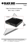
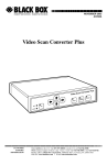
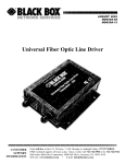
SAC510NA SAC510SA SAC500MSA SAC530NA Intelli-Pass™ Installation Guide Featuring enhanced biometric security BOX with two-factor authentication,BLACK providing the perfect blend of security and simplicity. ® Customer Support SAC510NA Order toll-free in the U.S.: Call 877-877-BBOX (outside U.S. call 724-746-5500) • FREE technical support 24 hours a day, 7 days a week: Call 724-746-5500 or fax 724-746-0746 • Mailing address: Black Box Corporation, 1000 Park Drive, Lawrence, PA 15055-1018 • Web site: www.blackbox.com • E-mail: [email protected] Trademarks Used in this Manual Trademarks Used in this Manual Black Box and the Double Diamond logo are registered trademarks, and Intelli-Pass is a trademark, of BB Technologies, Inc. Any other trademarks mentioned in this manual are acknowledged to be the property of the trademark owners. We‘re here to help! If you have any questions about your application or our products, contact Black Box Tech Support at 724-746-5500 or go to blackbox.com and click on “Talk to Black Box.” You’ll be live with one of our technical experts in less than 30 seconds. Page 2 724-746-5500 | blackbox.com SAC510NA FCC and Industry Canada RFI Statements Federal Communications Commission and Industry Canada Radio Frequency Interference Statements This equipment generates, uses, and can radiate radio-frequency energy, and if not installed and used properly, that is, in strict accordance with the manufacturer’s instructions, may cause interference to radio communication. It has been tested and found to comply with the limits for a Class A computing device in accordance with the specifications in Subpart B of Part 15 of FCC rules, which are designed to provide reasonable protection against such interference when the equipment is operated in a commercial environment. Operation of this equipment in a residential area is likely to cause interference, in which case the user at his own expense will be required to take whatever measures may be necessary to correct the interference. Changes or modifications not expressly approved by the party responsible for compliance could void the user’s authority to operate the equipment. This digital apparatus does not exceed the Class A limits for radio noise emission from digital apparatus set out in the Radio Interference Regulation of Industry Canada. Le présent appareil numérique n’émet pas de bruits radioélectriques dépassant les limites applicables aux appareils numériques de la classe A prescrites dans le Règlement sur le brouillage radioélectrique publié par Industrie Canada. SAC510NA Page 3 NOM Statement Instrucciones de Seguridad (Normas Oficiales Mexicanas Electrical Safety Statement) 1. Todas las instrucciones de seguridad y operación deberán ser leídas antes de que el aparato eléctrico sea operado. 2. Las instrucciones de seguridad y operación deberán ser guardadas para referencia futura. 3. Todas las advertencias en el aparato eléctrico y en sus instrucciones de operación deben ser respetadas. 4. Todas las instrucciones de operación y uso deben ser seguidas. 5. El aparato eléctrico no deberá ser usado cerca del agua—por ejemplo, cerca de la tina de baño, lavabo, sótano mojado o cerca de una alberca, etc.. 6. El aparato eléctrico debe ser usado únicamente con carritos o pedestales que sean recomendados por el fabricante. 7. El aparato eléctrico debe ser montado a la pared o al techo sólo como sea recomendado por el fabricante. 8. Servicio—El usuario no debe intentar dar servicio al equipo eléctrico más allá a lo descrito en las instrucciones de operación. Todo otro servicio deberá ser referido a personal de servicio calificado. 9. El aparato eléctrico debe ser situado de tal manera que su posición no interfiera su uso. La colocación del aparato eléctrico sobre una cama, sofá, alfombra o superficie similar puede bloquea la ventilación, no se debe colocar en libreros o gabinetes que impidan el flujo de aire por los orificios de ventilación. 10. El equipo eléctrico deber ser situado fuera del alcance de fuentes de calor como radiadores, registros de calor, estufas u otros aparatos (incluyendo amplificadores) que producen calor. 11. El aparato eléctrico deberá ser connectado a una fuente de poder sólo del tipo descrito en el instructivo de operación, o como se indique en el aparato. 12. Precaución debe ser tomada de tal manera que la tierra fisica y la polarización del equipo no sea eliminada. 13. Los cables de la fuente de poder deben ser guiados de tal manera que no sean pisados ni pellizcados por objetos colocados sobre o contra ellos, poniendo particular atención a los contactos y receptáculos donde salen del aparato. 14. El equipo eléctrico debe ser limpiado únicamente de acuerdo a las recomendaciones del fabricante. 15. En caso de existir, una antena externa deberá ser localizada lejos de las lineas de energia. 16. El cable de corriente deberá ser desconectado del cuando el equipo no sea usado por un largo periodo de tiempo. 17. Cuidado debe ser tomado de tal manera que objectos liquidos no sean derramados sobre la cubierta u orificios de ventilación. 18. Servicio por personal calificado deberá ser provisto cuando: A: El cable de poder o el contacto ha sido dañado; u B: Objectos han caído o líquido ha sido derramado dentro del aparato; o C: El aparato ha sido expuesto a la lluvia; o D: El aparato parece no operar normalmente o muestra un cambio en su desempeño; o E: El aparato ha sido tirado o su cubierta ha sido dañada. Page 4 724-746-5500 | blackbox.com SAC510NA Table of Contents Chapter Page 1. Specifications . ....................................................................................................................................................................... 6 2. Overview . ....................................................................................................................................................................... 7 2.1 Introduction..................................................................................................................................................................... 7 2.2 What’s Included............................................................................................................................................................... 7 2.3 Head Unit Front Section................................................................................................................................................... 8 2.4 Head Unit Back Section................................................................................................................................................... 8 2.5 Control Unit..................................................................................................................................................................... 9 3. Installing the Intelli-Pass........................................................................................................................................................... 10 3.1 Installing the Head Unit.................................................................................................................................................. 10 3.1.1 Front Section......................................................................................................................................................... 10 3.1.2Back Section.......................................................................................................................................................... 10 3.2 Installing the Control Unit.............................................................................................................................................. 10 3.3 Connecting the Head Unit to the Control Unit.............................................................................................................. 11 3.4 Connecting the Power Source to the Control Unit......................................................................................................... 12 3.5 Connecting an Electric Strike to the Control Unit........................................................................................................... 13 3.5.1 Fail-Safe Locks and Magnetic Locks (12V)............................................................................................................. 13 3.5.2 Fail-Secure Locks (12V).......................................................................................................................................... 14 3.5.3 Fail-Safe Locks and Magnetic Locks (24V)............................................................................................................. 14 3.5.4 Fail-Secure Locks (24V).......................................................................................................................................... 15 3.6 Request to Exit (RTE) Switch.......................................................................................................................................... 15 3.7 Door Sensor................................................................................................................................................................... 16 3.8 Fire Panel Integration..................................................................................................................................................... 18 3.9 Alarm Output................................................................................................................................................................. 19 3.10 Wiegand Output (26-Bit Protocol)................................................................................................................................. 21 3.11 Network Connection..................................................................................................................................................... 22 3.12 Powering On the Unit.................................................................................................................................................... 22 SAC510NA Page 5 Chapter 1: Specifications 1. Specifications Battery Backup Time: 8 hours Encryption: Proprietary algorithm (head-unit-to-controller communications) User Controls: 12-digit keypad, LCD menu Power: Input: 100–240 VAC, 50–60 Hz; Output: 18.5 VDC, 3.5 amps, 65 watts Size: Control Unit: 10.5"H x 10.3"W x 4"D (26.7 x 26.2 x 10.2 cm); Head Unit: 5.8"H x 7.5"W x 2.4"D (14.6 x 19.1 x 6 cm) Page 6 724-746-5500 | blackbox.com SAC510NA Chapter 2: Overview 2. Overview 2.1 Introduction The Intelli-Pass gives you a complete, secure door-access system. Use it to protect your doors from unauthorized access, notify you when a door is propped open, and get out of the building fast in case of a fire. It works with magnetic locks and electric strike locks to provide fail-safe or fail-secure door lock operation. A fail-safe lock requires power to keep it locked. A fail-secure lock stays locked even without power, but requires power to open it from the outside. The following Intelli-Pass models are available: • SAC510NA (networked, requires management software) • SAC510SA (standalone) • SAC530NA (triad, includes a card reader, requires management software) • SAC500MSA (management software) The Intelli-Pass consists of two components: a head unit and a control unit. The head unit has two parts (a front section and a back section), and mounts on a wall next to the door you want to control. You can place the control unit above a false ceiling, or way out of general reach, since you will not need to access it once you install the Intell-Pass system. This quick-start guide describes how to install the Intelli-Pass and how to set up user access to the door. 2.2 What’s Included Your package should include the following items. If anything is missing or damaged, please contact Black Box Technical Support at 724-746-5500. • Head unit (2 pieces) • Control unit • Installation template and screws • Black Box® 20' patch cord (for SAC510NA only) • 18.5-VDC power supply • U.S. power cord • This installation guide (printed) • Software manual and PC software on CD-ROM SAC510NA Page 7 Chapter 2: Overview 2.3 Head Unit Front Section Figure 2-1 shows the Intelli-Pass head unit’s front section. 2-line LCD display Fingerprint scanner area t ea Keypad Figure 2-1. Head unit’s front section. 2.4 Head Unit Back Section Figure 2-2 illustrates the Intelli-Pass head unit’s back section. Mounting holes Cable passageway Figure 2-2. Head unit’s back section. Page 8 724-746-5500 | blackbox.com SAC510NA Chapter 2: Overview 2.5 Control Unit Figure 2-3 illustrates the control unit. Figure 2-3. Control unit. SAC510NA Page 9 Chapter 3: Installing the Intelli-Pass 3. Installing the Intelli-Pass 3.1 Installing the Head Unit 3.1.1 Front Section Locate a surface adjacent to the opening side of the door, making sure that a person can stand directly in front of the unit without obstruction. Position the unit (where possible) on the wall so that the user’s forearm is at an angle approximately 90 degrees to the wall during operation. NOTE: Install the Intelli-Pass at a height that conforms to ADA requirements and local codes. NOTE: Make sure there is enough clearance to allow the door to open without banging the head unit. Before attaching the back section of the head unit, double check that the cable passageway through the wall is clear from obstruction (for example, pipes, cables, etc.). 3.1.2 Back Section 1. Use the template provided in Appendix A to position the back section on the wall. Use a spirit level to ensure that the plate is level. 2. Mark the four screw holes and cable passageway (bottom right) with a pencil on the wall. 3. Drill and plug (where necessary) the wall where you will install four mounting screws. 4. Drill through the wall where you have marked the cable passageway. Leave enough room so that the cable can pass directly into the rear of the unit. 5. Mount the back plate of the head unit to the wall using screws appropriate for the surface being fastened to (screws not included). 3.2 Installing the Control Unit Place the control unit above false ceilings or way out of reach, or locate it centrally in a communications closet. NOTE: You will not need to access the control unit during normal operation, but you will need to access it for annual battery checks and/or replacement. 1. Remove the 12-V battery before installing the unit. 2. Locate a suitable flat surface on the inside of the protected door. 3. Make sure the unit is level, then mark the four screw holes with a pencil on the wall. 4. Drill the four holes and insert appropriate screws and anchors (where necessary); use mounting hardware appropriate to the wall surface (wood, metal, drywall, concrete, etc.). 5. Mount the control unit to the wall screws installed in Step 4. Tighten the screws to hold the box in place. Page 10 724-746-5500 | blackbox.com SAC510NA Chapter 3: Installing the Intelli-Pass 3.3 Connecting the Head Unit to the Control Unit 1. Once the back plate of the head unit and the control unit are securely mounted, run a 4-pair (8-conductor) Belden 9504 cable (available from Black Box) or equivalent cable between the control unit and head unit. 2. The cable will exit the control unit via one of the push-out holes located on the bottom of the unit, running neatly along the wall and into the hole drilled through the rear of the head unit. Leave approximately 12" (300 mm) of spare cable at each end so that you can strip the wires and connect them to the terminal blocks. 3. Wire the head unit as shown in Figure 3-1. The actual colors are not important, but make sure you connect each pair of wires as shown in the diagram. 4. To simplify the wiring, you can remove the 2-part connectors from the boards. 5. Strip approximately 1⁄4" (6 mm) of sheath from each cable, braid the end, and insert into terminal blocks, checking that all wires are securely fastened. 6. Repeat Steps 3–5 at the control unit. Figure 3-1. Connecting the control unit to the head unit. SAC510NA Page 11 Chapter 3: Installing the Intelli-Pass 3.4 Connecting the Power Source to the Control Unit Make sure that you have a power outlet near the control unit that will ONLY be used to supply power to the control unit. CAUTION: Use ONLY the power supply you received from Black Box to power the control unit (or an exact equivalent). 1. Strip approximately 1⁄4” (6 mm) of plastic sheath from each cable to the power supply and connect to the appropriate terminal blocks, checking that all wires are securely fastened. (The power supply leads will be modified at the factory.) 2. If you previously removed the battery (as recommended in Section 3.2), reinstall it and fasten securely. 3. Reconnect the battery as shown in Figure 3-2. Figure 3-2. Connecting the power source to the control unit. Page 12 724-746-5500 | blackbox.com SAC510NA Chapter 3: Installing the Intelli-Pass 3.5 Connecting an Electric Strike to the Control Unit Fit an appropriate lock to the door. NOTE: The type of lock used determines how you wire the control unit. Figure 3-3. Linking an electric strike to the control unit. 3.5.1 Fail-Safe Locks and Magnetic Locks (12V) A fail-safe or magnetic lock has a permanent 12V supply to keep the lock closed. 1. Connect the Ground Lead of the lock to a terminal labeled GND. 2. Connect the Live Lead of the lock to the terminal labeled SOL. 3. Connect a link between Link and NC and a link between COM and 12V. Figure 3-4. Fail-safe or magnetic locks (12V) door controls. SAC510NA Page 13 Chapter 3: Installing the Intelli-Pass 3.5.2 Fail-Secure Locks (12V) A fail-secure lock requires a 12V supply to open the lock. 1. Connect the Ground Lead of the lock to the terminal labeled GND. 2. Connect the Live Lead of the lock to the terminal labeled SOL. 3. Connect a link between Link and NO and a link between COM and 12V. Figure 3-5. Fail-secure lock (12V) door controls. 3.5.3 Fail-Safe Locks and Magnetic Locks (24V) A fail-safe or magnetic lock has a permanent 24V supply to keep the lock closed. The Intelli-Pass controller does not supply a 24V output. To use a 24V lock, you will need a separate power supply. Wire a 24V fail-safe lock as shown in Figure 3-6. Figure 3-6. Fail-safe and magnetic locks (24V) door controls. Page 14 724-746-5500 | blackbox.com SAC510NA Chapter 3: Installing the Intelli-Pass 3.5.4 Fail-Secure Locks (24V) A fail-secure lock requires a 24V supply to open the lock. The Intelli-Pass controller does not supply a 24V output. To use a 24V lock, you will need a separate power supply. Wire a 24V fail-secure lock as shown in Figure 3-7. Figure 3-7. Fail-secure locks (24V) door controls. 3.6 Request to Exit (RTE) Switch The control unit has a built-in delay for the RTE switch. Connect a push switch as shown in Figure 3-8. The exit delay is set through the PC software on a networked unit or through the menus on the head unit for a standalone. Only use a normally open (N.O.) momentary switch in this application. v Figure 3-8. Request to exit (RTE) switch. SAC510NA Page 15 Chapter 3: Installing the Intelli-Pass 3.7 Door Sensor The Intelli-Pass uses the door sensor contacts for the forced door and propped door features. Connect the door sensor as shown in Figure 3-9. Only use a normally open (N.O.) switch in this application. Connect to sensor located in door and door jam. Door Figure 3-9. Door sensor. The door sensor circuit provides a feature to work with a special type of door sensor that is tamper-proof. This prevents an internal security breach, where someone with authorized access to an area could potentially short-out the contacts on the door sensor. If you’re using it with the anti-tamper door sensors, set the SW SEL (JMP1) jumper as shown in Figure 3-12. Figure 3-10. Tamper-proof door sensor. Page 16 724-746-5500 | blackbox.com SAC510NA Chapter 3: Installing the Intelli-Pass Door SW Exit SW KEY 4-6 tamper 2-4 normal 3-5 tamper 1-3 normal Figure 3-11. Jumper settings when used with a normal door sensor. Door SW Exit SW KEY 4-6 tamper 2-4 normal 3-5 tamper 1-3 normal Figure 3-12. Jumper settings when used with an anti-tamper door sensor. NOTE: Do not move the jumper connecting pins 1 and 3 in Figures 3-11 and 3-12. This jumper is reserved for future use. If you aren’t using the door sensor, keep the link in place as shown in Figure 3-13. Figure 3-13. Door sensor not used. Page 17 Chapter 3: Installing the Intelli-Pass 3.8. Fire Panel Integration To automatically unlock doors in case of a fire, you can connect units to a fire panel. 1. Once you unlock a door via the fire override inputs, press the reset button on the control unit (see Figure 3-14) to reset the unit manually. Doors will remain unlocked until you reset the unit. 2. Figure 3-14 shows how to connect a control unit to a fire panel. Connect the unit to either a normally open or normally closed set of contacts as shown in Figures 3-14 and 3-15. Figure 3-14. Connect the control unit to the fire panel. 3. Only remove the link between NO and NC if the system is wired as follows. Figure 3-15. Fire panel free panel output wiring. Page 18 Chapter 3: Installing the Intelli-Pass Figure 3-16 shows the location of the Reset switch. If you are not using the fire panel integration, keep the link in place as shown in Figure 3-17. Figure 3-16. Reset switch. 4. If the fire panel integration is not being used, the link between GND and NC must remain in place as shown. Figure 3-17. Fire panel not used. 3.9 Alarm Output Certain conditions that occur on the unit will cause the Alarm Relay to operate. The Alarm Relay can be used to connect the control unit to a third-party system. When one of the following conditions happens, the Intelli-Pass alerts the third-party system. The following will send an alarm alert: • Tampering detected on the head unit • A forced door • A door being propped open • The duress feature is activated • The external alarm is active, such as in a fire control system. The alarm relay is connected as shown in Figures 3-18 and 3-19. SAC510NA Page 19 Chapter 3: Installing the Intelli-Pass Figure 3-18. Alarm input relay, normally closed. Figure 3-19. Alarm panel relay, normally open. Or, the Intell-Pass can use the alarm relay to power a third-party buzzer or siren. See Figure 3-20. Page 20 724-746-5500 | blackbox.com SAC510NA Chapter 3: Installing the Intelli-Pass Figure 3-20. Using the alarm relay to power a third-party buzzer or siren. 3.10 Wiegand Output (26-Bit Protocol) The Intelli-Pass controller offers a 26-bit Wiegand output for seamless integration into a third-party access control system. Figure 3-21 shows how to connect a control unit to a third-party system. Figure 3-21. Connecting a control unit to a third-party system. 724-746-5500 | blackbox.com SAC510NA Page 21 Intelli-Pass Quick Start Guide 3.11 Network Connection If the unit is networked, connect the RJ-45 plug as shown in Figure 3-22. Figure 3-22. Network connection. 3.12 Powering On the Unit 1. Verify that the battery is connected. 1. Plug the power supply into the power outlet and make sure that the supply is switched on. 2. The unit should now power on. If not, unplug the unit and check all wiring. 3. The buzzer on the control unit should sound for one second. 4. Check the LCD display. 5. If the display reads LCD CONTRAST (0-9):[0] #=DONE, the unit is OK. 6.If the unit does not get to this stage or displays a different message, disconnect the power cord and make sure the cable between the head unit and control unit is wired correctly. NOTE: Fingerprint sensor and communications errors can take up to 15 seconds to appear. The LCD display will remain blank until the error message is displayed. Now that your Intelli-Pass is installed, go to Chapter 4 for software setup instructions. Page 22 724-746-5500 | blackbox.com SAC510NA Black Box Tech Support: FREE! Live. 24/7. Tech support the way it should be. Great tech support is just 30 seconds away at 724-746-5500 or blackbox.com. About Black Box Black Box Network Services is your source for more than 118,000 networking and infrastructure products. You’ll find everything from cabinets and racks and power and surge protection products to media converters and Ethernet switches all supported by free, live 24/7 Tech support available in 30 seconds or less. © Copyright 2011. All rights reserved. SAC510NA Installation Guide, rev. 2 724-746-5500 | blackbox.com