1
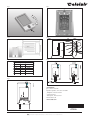
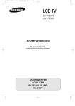
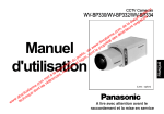
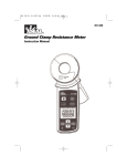
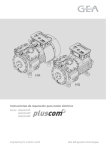
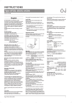
67028A-05-10.qxp:57609
06/05/10
12:29
Side 2
I NSTRUCTTI O
I ONNSS
I NSTRUC
TypeUDG,
UDG,UCG,
UCG,UTN,
UTN,USG
USG
Type
67028A
05/10
(MBC)
67028A
05/10
(MBC)
Français
Le thermostat est du type électronique on/off
pour le contrôle de température par une sonde
NTC externe ou interne. Le thermostat possède
un disjoncteur de fuite à la terre intégré (GFCI,
Classe
A). Le is
thermostat
et le on/off
disjoncteur
thermostat
is an
electronic
on/off de
TheThe
thermostat
an
electronic
fuite à la for
terre
intégré
sontcontrol
conçus
pour
des of of
thermostat
for
temperature
control
by
means
thermostat
temperature
by
means
alimentations
à 120-240
V (y compris
208 or
V) et
NTC
sensor
located
either
externally
an an
NTC
sensor
located
either
externally
or
50/60 Hz. within the thermostat. The thermostat
internally
internally
within the thermostat. The thermostat
Le thermostat
est conçu
pour
un montage
a built-in
ground
fault
circuit
interrupter
hashas
a built-in
ground
fault
circuit
affleurant
dans
un boîtier
mural.interrupter
(GFCI,
Class
thermostat
GFCI
(GFCI,
Class
A). A).
TheThe
thermostat
andand
GFCI
areare
suitable
for
120-240
V (incl.
208V)
50/60
Hz
suitable
for
120-240
V
(incl.
208V)
50/60
Hz
Gamme de produits
power
supplies.
power
supplies.
Thermostat
avec
disjoncteur
de
fuite
à
la
terre
thermostat
is for
flush
mounts
a wall
TheThe
thermostat
is for
flush
mounts
in ainwall
intégré
socket.
socket.
UCG-4991 Thermostat à horloge incluant une
Product
programme
Product
programme
sonde de sol
Thermostats
with
built-in
GFCI incluant 2
UDG-4999with
Thermostat
à horloge
Thermostats
built-in
GFCI
sondes
: sonde
de
sol et sonde
UCG-4991
Programmable
thermostat
UCG-4991
Programmable
thermostat
incl.incl.de
pièce
intégrée
floor
sensor
floor
sensor
UTN-4991Programmable
Thermostat
dethermostat
base
incluant
une
UDG-4999
Programmable
thermostat
UDG-4999
withwith
sonde
de sol
2 sensors:
2 sensors:
Module defloor
puissance
incluant
disjoncteur
de
floor
sensor
built-in
room
sensor
andand
built-in
room
fuite à la terre
intégré
sensor
sensor
USG-4000Non-programmable
Module
de puissance
sans sonde
UTN-4991
Non-programmable
thermostat
UTN-4991
thermostat
floor
sensor
incl.incl.
floor
sensor
English
English
Montage de la sonde de sol (fig. 3)
Power
module
built-in
GFCI
La sonde
dewith
solwith
est
alimentée
par un circuit
Power
module
built-in
GFCI
d'énergie trèsPower
basse module
tension without
(SELV) permettant
USG-4000
sensor
USG-4000
Power
module
without
sensor
à la sonde d’être placée aussi près de la
surface
du
sol
que
souhaité
sans
prendre
de
Mounting
of floor
sensor
3)
Mounting
ofparticulières
floor
sensor
(fig.(fig.
mesures
contre
le3)SELV
risque(Safety Extra
Floor
sensor
is supplied
from
Floor
sensor
is
supplied
from
SELV
(Safety
Extra
d’électrisation
par un allowing
dommage
ausensor
câble de
Voltage)
Circuit,
to la
be
lowlow
Voltage)
Circuit,
thelethe
sensor
be
sonde.
Il n’est
pasallowing
que
fil de lato
placed
as close
toprévu
the
floor
surface
assonde
desired
placed
as
close
to
the
floor
surface
as
desired
de température pénètre la boîte de montage du
without
having to take
special
account
to the
without
special
account
toêtre
the
boîtierhaving
mural.toLetake
câble
de la sonde
doit
of shock
at the
damage
to the
sensor
cable.
riskrisk
of shock
the
damage
to the
sensor
cable.
séparé
desatcâbles
d’ALIMENTATION
et de
is not
intended
temperature
sensorà
It isIt
not
intended
thatthat
thethe
temperature
sensor
PUISSANCE.
Peut
être
séparé
dans un
conduit
shall
enter
through
the
wall
socket
wirewire
shall
enter
thedu
wall
socket
l’intérieur
ou
àthrough
l’extérieur
mur.
(Voir
Figure. 7)
mounting
box.
sensor
cable
shall
mounting
box.
TheThe
sensor
cable
shall
be be
seperated
from
LINE
LOAD
cables.
seperated
from
LINE
and
cables.
be be
Il est recommandé
de and
leLOAD
placé
dans
uneCanCan
separated
in conduite,
inside
or outside
the
separated
conduite,
inside
or outside
the
conduiteind’installation
non
conductrice
enfouie
wall.
7) 3). La conduite doit être
dans
lefig.
solfig.
(Figure
wall.
(see(see
7)
scellée aux bouts et localisée le plus haut
Recommended
in
non
conductive
possible dansplaced
la placed
couche
dean
béton.
De façon
Recommended
in an
non
conductive
installation
pipe,
which
is embedded
in the
floor.
alternative,
la
sonde
de
sol
est montée
installation
pipe,
which
is embedded
in the
floor.
pipe
must
be
sealed
in the
directement
dans
la be
construction
du
plancher.
(fig.(fig.
3). 3).
TheThe
pipe
must
sealed
in the
endend
andand
Le câble
la
doitin
être
dans layer.
unelayer.
placed
asdehigh
as possible
in placé
the
concrete
placed
as high
assonde
possible
the
concrete
conduite séparée
ou
séparé
des
dedirectly
Alternativerly,
floor
sensor
iscâbles
monted
Alternativerly,
thethe
floor
sensor
is
monted
directly
puissance.
La
sonde deThe
sol
doit
être
centrée
in
the
floor
construction.
The
sensor
cable
shall
in the
floor
construction.
sensor
cable
shall
entre
lesincâbles
de chauffage.
placed
a separate
pipe
or be
separated
be be
placed
ainseparate
pipe
or be
separated
from
power
cables.
from
power
cables.
Le câble
de
la sonde
peut être
rallongé
jusqu’à
floor
sensor
must
centered
in between
TheThe
floor
sensor
must
be be
centered
in between
100 heating
m par uncable.
câble à deux fils séparés. Les
thethe
heating cable.
deux fils restants dans un câble multibrin qui,
par exemple,
sert àbe
l'alimentation
detocâbles
Sensor
cable
extended
300
ft (100
Sensor
cable
cancan
be
extended
up up
to 300
ft (100
chauffants
d’un
système
de chauffage
du
sol, Two
by
means
ofseparate
a separate
two-core
cable.
m.)m.)
by
means
of
a
two-core
cable.
Two
ne doivent pas être utilisés. Le câble à deux fils
remaining
cores aofmulti-core
a multi-core
cable
which,
remaining
cable
which,
for for
doit êtrecores
placéof
dans une conduite
séparée
ou
example,
supplies
current
to the
floor
heating
example,
current
to the
floor
heating
séparé supplies
des câbles
de puissance.
wires,
must
used.
two-core
cable
wires,
must
notnot
be be
used.
TheThe
two-core
cable
must
placed
asol
separate
pipe
or
be
must
be be
placed
in ain
separate
pipe
or be
D’autres
sondes
de
peuvent
être
utilisées
si
separated
from
power
cables.
separated
from
power
cables.
elles sont
conformes
aux
spécifications
techniques (voir fig. 5).
Other
approved
floor
sensors
used
Other
approved
floor
sensors
cancan
be be
used
if if
they
comply
the
technical
specifications
they
comply
withwith
the
technical
specifications
Montage
d’un
thermostat
avec
sonde
intégrée
(see(see
fig.fig.
5). 5).
(UDG-4999) (fig. 4)
Mounting
ofpièce
thermostat
with
built-in
sensor
La sonde
est utilisée
pour
la sensor
régulation
Mounting
ofde
thermostat
with
built-in
(UDG-4999)
de la température
de confort dans des pièces.
(UDG-4999)
(fig.(fig.
4) 4)
room
sensor
isêtre
used
for
comfort
Leroom
thermostat
doit
monté
sur le mur à
TheThe
sensor
is used
for
comfort
environ 1,6regulation
mregulation
au dessus
sol The
de The
façon à
temperature
indurooms.
temperature
in rooms.
permettreshould
une
libre
d’air
de
thermostat
should
be
mounted
on
the
thermostat
be circulation
mounted
on
theautour
wallwall
lui. Les
d’air
et
lathe
lumière
directe
du
approx.
5.4
ft (1.6
m)
above
the
floor
in such
approx.
5.4courants
ft (1.6
m)
above
floor
in such
a a
soleil
ouallow
sources
de
chaleur
sont
àit.éviter.
as
toautres
allow
free
circulation
around
it.
wayway
as to
free
air air
circulation
around
Draughts
direct
sunlight
or other
heat
Draughts
andand
direct
sunlight
or other
heat
Montagemust
sources
be
avoided.
sources
mustdu
bethermostat
avoided.
Installation
POUR ÉVITER UNE ÉLECTROCUTION,
DÉBRANCHEZ LA SOURCE D’ALIMENTATION
DU SYSTÈME DE CHAUFFAGE AU PANNEAU
PRINCIPAL AVANT L’INSTALLATION DU
THERMOSTAT.
MAINTENEZ LES ÉVENTS DU THERMOSTAT
PROPRES ET LIBRES D’OBSTRUCTION.
CeMounting
thermostat
un appareil électrique et doit
ofest
thermostat
Mounting
of thermostat
être
installé en respectant le code de l’électricité
Installation
Installation
national
et/ou
local. L’installation
doit
être
TO
AVOID
ELECTRIC
SHOCK,
DISCONNECT
TO
AVOID
ELECTRIC
SHOCK,
DISCONNECT
exécutée
par du
personnel
qualifié
oùSUPPLY
cela est
THE
HEATING
SYSTEM
POWER
THE
HEATING
SYSTEM
POWER
SUPPLY
AT AT
requis
par
la loi.
Le thermostat
est
muni d’un THE
THE
MAIN
PANEL
BEFORE
INSTALLING
THE
MAIN
PANEL
BEFORE
INSTALLING
THE
disjoncteur
de fuite à la terre intégré (GFCI,
THERMOSTAT.
THERMOSTAT.
Classe
A)THERMOSTAT
qui requiert queAIR
lesVENTS
câbles CLEAN AND
KEEP
KEEP
THERMOSTAT
AIR VENTS
CLEAN AND
d’alimentation
etOBSTRUCTION.
de charge soient isolés les uns
FREE
FROM
FREE
FROM
OBSTRUCTION.
des
autres
pour uneisopération
adéquate.
Le
This
thermostat
an
electrical
product
This
thermostat
is an electrical
product
andand
thermostat
est
conçu
une charge
résistive.
must
be
installed
inpour
compliance
with
the
must
be
installed
in
compliance
with
the
La charge résistive ne doit pas excéder 15 A
National and/or
Local
Electrical
Code.
National
Local
Electrical
Code.
(1800 W and/or
à 120 VCA
/ 3120
W à 208
VCA /3600
Installation
must
performed
qualified
Installation
must
be be
performed
by by
qualified
W à 240 VCA).
personnel
where
required
personnel
where
required
by by
law.law.
TheThe
thermostat
is equipped
adeux
ground
fault
thermostat
is faute
equipped
withwith
a
fault
Pendant
une
à la terre,
lesground
lignes
circuit
interrupter
(GFCI,
Class
A) which
requires
circuit
interrupter
(GFCI,
Class
A) which
requires
seront
coupées.
load
cables
isolated
from
thatthat
thethe
lineline
andand
load
cables
areare
isolated
from
one
another
correct
operation.
one
another
for for
correct
operation.
TheThe
Câble
d’alimentation
thermostat
is designed
resistive
load.
thermostat
is puissance
designed
for
resistive
load.
TheThe
Achemine
la
du for
panneau
de
service
resistive
load
must
15
A (1800
W at
(panneau
coupe-circuit
ou exceed
boîte15
à fusible)
vers
resistive
load
must
notnot
exceed
A (1800
W at
120
/ 3120
W 208
at 208
/ 3600
W 240
at 240
le thermostat.
120
VacVac
/ 3120
W at
VacVac
/ 3600
W at
CeVac).
câble doit uniquement être raccordé aux
Vac).
borniers d’alimentation du thermostat identifiés
a ground
fault,
lines
L1During
et L2.
During
a ground
fault,
thethe
twotwo
lines
willwill
be be
cutcut
off.off.
Câble de charge
Achemine
la puissance du thermostat au câble
Line
cable
Line
cable
chauffant.
Delivers
power
from
service
panel
(breaker
Delivers
power
from
thethe
service
panel
(breaker
Cepanel
câble
doit
uniquement
être
raccordé aux
or
fuse
box)
to the
thermostat.
panel
or fuse
box)
to the
thermostat.
borniers
de
charge
du
thermostat
identifiés
cable
must
connected
to the
ThisThis
cable
must
onlyonly
be be
connected
to the
charge
15 A. line terminals, marked L1 and L2.
thermostat’s
thermostat’s
line terminals, marked L1 and L2.
1. Load
Utilisez
un tournevis pour libérer le fermoir
cable
Load
(fig.cable
1), etpower
retirezfrom
le couvercle
avant. to the
Delivers
the
thermostat
Delivers
power
theselon
thermostat
to (fig.
the 2)
2. Raccordez lesfrom
câbles
le schéma
heating
cable.
heating
cable.
3. Montez le thermostat dans le boîtier mural.
This
cable
must
connected
to the
This
cable
must
onlyonly
be be
connected
to the
4. Remettez
soigneusement
le couvercle
avant
thermostat’s
load
terminals,
marked
load
thermostat’s
terminals,
marked
load
15 15
A. A.
en insérantload
d’abord
sa bordure
du haut
puis
en le poussant jusqu’à ce qu’il clique en
1.
Use
a screwdriver
to release
catch
1. Use
a screwdriver
to release
thethe
catch
(fig.(fig.
1), 1),
place.
remove
front
cover
andand
remove
thethe
front
cover
2. Connect
cables
according
to the
diagram
2.Sonde
Connect
according
to the
diagram
(fig.(fig.
2) 2)
de cables
température
3.
Mount
thermostat
in the
3.LaMount
the
thermostat
the
wallwall
socket.
sonde
dethe
sol
doit être in
raccordée
auxsocket.
4. Carefully
replace
the
front
cover
by
marqués
« the
sensor
» (sonde),
4.borniers
Carefully
replace
front
cover
byborniers
firstfirst C
its upper
edge
then
clicking
etpositioning
D. positioning
(Figure 6).
its upper
edge
andand
then
clicking
it it
place.
intointo
place.
Module de puissance, type USG
Si Temperature
des chargessensor
desensor
plus de 15 A sont requises,
Temperature
une
extension
estmust
possible
enconnected
utilisanttodes
The
floor
sensor
must
to
The
floor
sensor
be be
connected
modules
de
puissance.
terminals
marked
“sensor”,
terminals
C and
terminals
marked
“sensor”,
terminals
C and
D. D.
Des
modules
de puissance peuvent être
(fig.
6).
(fig.
6).
raccordés au câble d’alimentation et au câble
dePower
charge,
voir les
sections
pertinentes.
module,
type
USG
Power
module,
type
USG
LaIfdistance
entreAleare
thermostat
loads
ofmaximum
more
than
required,et les
If loads
of more
than
15 15
A are required,
modules
de puissance
estusing
25 m.power modules.
expansion
is possible
expansion
is possible
using
power modules.
Utilisez
dumodules
câble decan
construction,
minimum
Power
be
connected
to the
Power
modules
can be Raccorder
connected
to the
livelive
recommandé
20 AWG.
AàC
et B à
cable
and
load
cable,
relevant
sections.
cable
and
load
cable,
seesee
relevant
sections.
D (fig.
6).
Maximum
distance
between
thermostat
Maximum
distance
between
thermostat
andand
power
modules
is 80
ft (25
power
modules
is 80
ft (25
m.)m.)
Fonctionnement
Use
field
wiring
cable,
recommended
min.
20
Use
field
wiring
cable,
recommended
min.
20
Types
UCG
et UDG
(avec
horloge intégrée)
:
AWG.
Connect
toand
C and
to(fig.
D (fig.
AWG.
Connect
toA C
B toB D
6). 6). le
La première
foisAque
vous mettez
en marche
thermostat, l’heure et le jour doivent être réglés.
Operation
LeOperation
thermostat démarrera automatiquement
Types
UCG
and
UDG
(with
built-in
clock):
Types
and
UDG
(with
built-in
avec
leUCG
menu
pour
régler
l’heure
et leclock):
jour.
time
thermostat
is connected,
TheThe
firstfirst
time
thethe
thermostat
is connected,
time
and
day
must
thermostat
time
and
day
must
be be
set.set.
TheThe
thermostat
willwill
Type
UTN
(sans
horloge
intégrée)
:
start
up
intempérature
the
menu
Leautomatically
réglage courant
pour
estsetting
automatically
start
up
in la
the
menu
for for
setting
time
montré
etday.
le day.
thermostat est prêt pour usage.
time
andand
secondes pour permettre au thermostat de
s’ajuster au nouveau point de consigne.
Puis, appuyez sur le bouton TEST (essai).
La vérification est concluante si la lumière rouge
duAdjust
bouton
(essai)
s’allume
etheating
quesymbol
Adjust
the
setpoint
until
symbol
theTEST
setpoint
until
thethe
heating
( () )
GROUND
FAULT
(faute
à la
terre)
apparait
surthethe
appears.
the
“Up”
button
to increase
appears.
UseUse
the
“Up”
button
to
increase
l’afficheur.
Si demand
ce n’est
lethen
cas,
vérifiez
heating
and
press
“OK”
heating
demand
andpas
then
press
thethe
“OK”
l’installation.
button.
Wait
seconds
to allow
thermostat
button.
Wait
10 10
seconds
to allow
thethe
thermostat
Appuyez
sur
Standby/Reset
to adjust
tobouton
the
setpoint.
to adjust
tolethe
newnew
setpoint.
(attente/réarmement)
pour réarmer
le
Then
press
“TEST”
button.
Then
press
thethe
“TEST”
button.
disjoncteur
deisfuite
à la terreif intégré.
successful
light
in the
TheThe
testtest
is successful
if thethe
redred
light
in the
La lumière
rouge
devrait
s’éteindre
et l’afficheur
“TEST”
button
lights
up
and
“GROUND
FAULT”
“TEST”
button
lights
up
and
“GROUND
FAULT”
reprendre
son on
apparence
normale.
is shown
the
display.
If this
does
not
occur,
is
shown
on
the
display.
If
this
does
not
occur,
Appuyez
surthe
le bouton
Down (baisse) pour
check
installation.
check
the
installation.
retourner au réglage initial de la température.
Press
“Standby/Reset”
button
to reset
thethe
“Standby/Reset”
button
to reset
thethe
SiPress
la vérification
échoue, vérifiez
le câble
GFCI.
GFCI.
chauffant
et le thermostat.
The
light
should go
out
and
display
redred
light
should
and
thethe
display
LeThe
disjoncteur
de
fuite go
à laout
terre
intégré
doit être
returns
to normal
appearance.
returns
to normal
appearance.
vérifié
mensuellement.
Press
“Down”
button
to return
to the
original
Press
thethe
“Down”
button
to return
to the
original
setting.
setting.
Sitemperature
le temperature
disjoncteur
de
fuite à la terre intégré se
If the
fails,
check
heating
cable
If the
testtest
fails,
check
thethe
heating
cable
andand
déclenche
pendant
l’opération
normale
sans
thermostat.
thermostat.
que
vous
appuyiez sur le bouton TEST (essai), il
should
be
monthly.
pourrait
yGFCI
avoir
une be
faute
àtested
la terre
! Pour vérifier
TheThe
GFCI
should
tested
monthly.
si c’est une faute à la terre ou un
If during
normal
operation
GFCI
trips
déclenchement
intempestif,
appuyez
sur
If during
normal
operation
thethe
GFCI
trips
without
“TEST”
button
being
there
Standby/Reset
(attente/réarmement).
Sipressed,
la
without
thethe
“TEST”
button
being
pressed,
there
could
a ground
To check
whether
lumière
rouge
s’éteint
et fault!
demeure
éteinte,
c’était
could
be be
a ground
fault!
To check
whether
it isitais a
unground
déclenchement
et le système
ground
fault
orintempestif
nuisance
tripping,
press
fault
or nuisance
tripping,
press
fonctionne
correctement.
Sicauses
cecauses
n’est
cas,
“Standby/Reset”.
If this
the
light
“Standby/Reset”.
If this
thepas
redlered
light
to to
il go
y a go
uneoff
faute
àstay
laoff,
terre
!it was
and
off,
nuisance
tripping
off
and
stay
it was
nuisance
tripping
andand
Vérifiez
lesystem
câble
chauffant,
le câble
de
is operating
correctly.
Ifsonde
this
does
thethe
system
is operating
correctly.
If la
this
does
etnot
le not
thermostat.
Remplacer
lesfault!
pièces
occur,
there
a ground
fault!
occur,
there
is aisground
défectueuses.
Check
heating
cable,
sensor
cable
Check
thethe
heating
cable,
sensor
cable
andand
thermostat.
Replace
defective
part.
thermostat.
Replace
thethe
defective
part.
Programmation
Voir le
mode d’emploi.
Programming
Programming
See
user manual.
See
user
Dépistage manual.
des erreurs
Si la sonde est débranchée ou court-circuitée,
Fault
location
Fault
location
le système de chauffage est arrêté. La sonde
If the
sensor
is disconnected
or short-circuited,
If the
sensor
is disconnected
or au
short-circuited,
peut
être
contrôlée
conformément
tableau
the
heating
system
is switched
sensor
therésistances
heating
system
off.off.
TheThe
sensor
des
(fig.
5).is switched
can
be
checked
against
the
resistance
table
can be checked against the resistance table
(fig.(fig.
5).
Code
des5).erreurs
E0: Erreur interne. Le thermostat doit être
Error
codes
Error
codes
remplacé.
E0:
Internal
error.
thermostat
must
E1:
interne
court-circuitée
ou must
E0:Sonde
Internal
error.
TheThe
thermostat
be be
replaced.Le thermostat doit être
déconnectée.
replaced.
E1:
Built-in
sensor
short-circuited
(s.o.
pour
UTN-4991)
E1:remplacé
Built-in
sensor
short-circuited
or or
disconnected.
thermostat
must
E2: Sonde
externe court-circuitée
ou must
disconnected.
TheThe
thermostat
be be
replaced
UTN-4991)
déconnectée.
replaced
(n/a(n/a
for for
UTN-4991)
External
sensor
short-circuited
E2:E2:
External
sensor
short-circuited
or or
c-UL-us
disconnected.
disconnected.
Selon les normes suivantes :
DISJONCTEUR
DE
FUITE
Àand
LA
TERRE
Listed
Canada
ULUL
Listed
forfor
thethe
USUS
and
Canada
Thermostat
: to the
873
According
toULthe
following
standards:
According
following
standards:
No. 24.
Thermostat:CSA
UL
Thermostat:
ULC22.2
873873
No. Dossier UL : E157297
CSA
C22.2
CSA
C22.2
No.No.
24.24.
INTÉGRÉ
: number:
UL 943
4th ed.
E157297
UL UL
file file
number:
E157297
CSA C22.2
Nº 144.1-06
GFCI:
GFCI:
UL UL
943943
4th4th
ed.ed.
CSA
C22.2
144.1-06
CSA
C22.2
No.No.
144.1-06
Classification
Le produit est un appareil de classe II (isolation
Classification
Classification
augmentée)
et doit être raccordé aux fils
product
a class
II device
(enhanced
TheThe
product
is aisclass
II device
(enhanced
suivants
:
insulation)
and
must
be
connected
to the
insulation)
must
be
connected
the
Phase
L1 (L) and
120-240
V ±10
%, 50/60toHz
following
leads:
following
leads:
Neutre
L2 (N)
Phase
120-240
V ±10%,
50/60
Phase
L1 L1
(L) (L)120-240
V ±10%,
50/60
Hz Hz
Charge
maximum
15
A (charge
résistive)
Neutral
Neutral
L2 L2
(N) (N)
Max.
load
15
A (resistive
load)
Max.
load
15
A (resistive
load)
Les
borniers
sont
adéquats
pour
du câble de
construction de 12 à 22 AWG.
terminals
suitable
field
wiring
cables
TheThe
terminals
areare
suitable
for for
field
wiring
cables
of 12
to 22
AWG.
Caractéristiques
techniques
of 12
to 22
AWG.
Type
UTN
(without
built-in
Vérification
du
disjoncteur
de clock):
fuite à la terre
Alimentation
. . . . . . . .120-240 VCA 50/60 Hz
Type
UTN
(without
built-in
clock):
Technical
The
actual
temperature
setting
is shown
intégré
. data
. . . .Max. 15 A (charge résistive)
Technical
data
The
actual
temperature
setting
is shown
andand
thethe Charge
Supply. . ..................................120-240
..1800
. .120-240
Vac
50/60
Il est
important
vérifier
l’installation
et le
thermostat
isde
ready
use.
Puissance
W àVac
120
VCA
Supply
50/60
Hz Hz
thermostat
is ready
for for
use.
fonctionnement du disjoncteur de fuite à la terre
.3120
W(resistive
àA208
VCA
Load . . ..........................max.
.. .. .max.
(resistive
load)
Load
15 15
A
load)
intégré.
W àW240
VCA
Power . . ......................... .. ..3600
....1.800
. . .1.800
W 120
at 120
Checking
GFCI
Power
at
VacVac
Checking
thethe
GFCI
lethat
disjoncteur
deisfuite
à la terre
Disjoncteur .de
...terre
. . .3.120
W 208
at 208
isvérifier
important
that
GFCI
is checked
. ..fuite
........à...la
...........3.120
W at
VacVac
ItPour
isItimportant
thethe
GFCI
checked
for for
intégré
: installation
intégré
(5240
mA,
..Classe
. .3.600
W
at
240
correct
function.
. . ........................................3.600
WAat
VacVac
correct
installation
andand
function.
LaTo
vérification
neGFCI:
peut s’effectuer que si le
déclenchement)
GFCI . . ............niveau
. . de
.Class
(5 mA
level)
check
GFCI
.......Class
A (5AmA
triptrip
level)
To
check
thethe
GFCI:
thermostat
active
le chauffage.
PlageTemperature
de
range
to +40°C,
to +104°F
Testing
performed
while
Temperature range
+5 +5
to +40°C,
+41+41
to +104°F
Testing
cancan
onlyonly
be be
performed
while
thethe
Réglez
le pointisde
consigne
jusqu’à ce que le
température
. . range
. .+5 à .+. 40
+41 à + +32
104 to
°F +77°F
Amb.
temp.
.0°C,
to +25°C,
thermostat
calling
heat.
Amb.
temp.
range
. . . .0.to
+25°C,
+32 to +77°F
thermostat
is calling
for for
heat.
symbole ( ) apparaisse. Utilisez le bouton Up
Plage de température
(hausse) pour accroître le besoin de chauffage
ambiante
. . . . .+0 à + 25 °C, +32 à + 77 °F
puis appuyez sur le bouton OK. Attendez 10
trademark
is registered
belongs
to Electronics
OJ Electronics
· © 2010
OJ Electronics
The The
trademark
is registered
and and
belongs
to OJ
A/S A/S
· © 2010
OJ Electronics
A/S A/S
Fig. 2
Fig. 3
Fig.4
Fig. 5
Fig. 6
Sensor
Temp.(˚C)
Temp.(˚F)
Value (ohm)
-10
-14
64000
0
10
32
50
20
30
68
86
38000
23300
14800
BR928A07
1,6m
Fig. 1
9700
BR0964A02
Fig. 7
CELSIAIR INC. Les Câbles Saint-Laurent Inc.
2713,avenue
Boul. Royale,
Louis XIV
947,
bur. 150,
QuébecQC
(Québec)
5S9 CANADA
Québec
G1E 1Z9G1C
CANADA
Téléphone :: (418)
418 663-7878
Téléphone
663-7878 •
1 866 930-7878
Sans
frais : 1 866 930-7878
Télécopieur
: (418)
663-7267
Télécopieur :
418 663-7267
[email protected]
[email protected]
www.momentoconfort.com
www.celsiair.com
1
2
1
2
The trademark is registered and belongs to OJ Electronics A/S · © 2010 OJ Electronics A/S