1
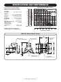
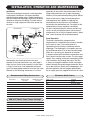
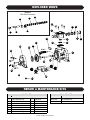
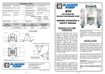
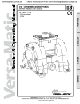
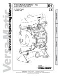
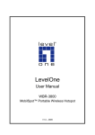
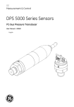
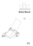
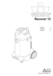
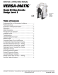
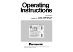
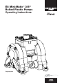
E8 Mini-Matic™ 3/8"
Bolted Plastic Pumps
Operating Instructions
Polypropylene
SAFETY WARNINGS
Read these instructions completely before installation and
start-up. It is the responsibility of the purchaser to retain
this manual for reference. Failure to comply with the recommendations stated in this manual could result in death,
serious bodily injury and/or property damage including
damage to the pump and/or voiding the factory warranty.
Before pump operation, inspect all gasketed fasteners for
looseness caused by gasket creep. Re-torque all loose
fasteners to prevent leakage. Follow recommended torques
stated in this manual. Failure of the sealing components
creates the possibility of jetting or forceful discharge of
pumped material at a potentially harmful velocity.
Correct pump selection is crucial to the pump operation.
Please assure pressure, temperature and chemical
compatibility before installation. Please consult Versa-Matic
Pump, Engineering Specifications, Chemical Compatibility
Chart, or your distributor if in doubt about any application.
Be certain that approved eye protection and protective
clothing are always worn during installation, service, maintenance or when in the vicinity of the pump. Failure to follow
these recommendations may result in serious injury or death.
Operating Limitations for Various Elastomers
Neoprene
Buna-N
Nordel
Viton
Teflon
Polyurethane
XL TPE
Geolast
FDA Hytrel
0°F (-18°C) to 200°F (93°C)
10°F (-12°C) to 180°F (82°C)
-60°F (-51°C) to 280°F (138°C)
-40°F (-40°C) to 350°F (176°C)
40°F (4°C) to 220°F (105°C)
10°F (-12°C) to 170°F (77°C)
-20°F (-29°C) to 300°F (149°C)
-40°F (-40°C) to 257°F (125°C)
-20°F (-29°C) to 220°F (104°C)
Never allow the piping system to be supported by the pump
manifolds or valve housing. The manifolds and valve housing
are not designed to support any structural weight and failure
of the pump may result.
Take action to prevent static sparking. Fire or explosion
can result, especially when handling flammable liquids. The
pump, piping, valves, containers, or other miscellaneous
equipment must be grounded.
Noise levels can exceed 85 dBA. Take precautions to prevent
personal injury due to excessive pump noise.
Operating Limitations for Plastic Pumps
Kynar (PVDF)
Polypropylene
10°F (-12°C) to 225°F (107°C)
32°F (0°C) to 175°F (79°C)
Maximum temperature limits are based upon mechanical
stress only. Certain chemicals and environment conditions
significantly reduce maximum safe temperature limits.
Do not exceed pump maximum operating pressure (found
on label and/or operating manual.)
Before doing any maintenance or repair on this pump,
be certain all pressure is completely vented for the pump,
suction, discharge, piping, and all other openings.
In the event of a diaphragm rupture, pumped material
may enter the air end of the pump and be discharged into
the atmosphere. If pumping a product that is hazardous
or toxic, the air exhaust must be piped to an appropriate
area for safe disposition.
Versa-Matic® Mini-Matic™ 3/8" Plastic Bolted OM
SPECIFICATIONS AND PERFORMANCE
Displacement Per Stroke, 0.0045 Gal. (0.017 L)
Flow Rate
Adjustable to . . . . . . . 0-8.2 gpm (31 lpm)
Port Size
Suction . . . . . . . . 3/8" Female NPT (BSP)
Discharge . . . . . . 3/8" Female NPT (BSP)
Air Inlet . . . . . . . . . . . . 0.25" Female NPT
Air Exhaust . . . . . . . . 0.25" Female NPT
Suction Lift . . . . . . . . . . . 11' (3.4 m) Dry
Teflon . . . . . . . . . . . . . . . . 11' (3.4 m) Dry
Max. Particle Size (Dia.) . . 0.10" (2.5 mm)
dB(A) Reading . . . . . . . . . . . . . . 78 dB(A)
Shipping Weight
Polypropylene . . . . . . . . . . . 3 lbs (1.4 kg)
Kynar . . . . . . . . . . . . . . . . . . 3 lbs (1.4 kg)
75
70
65
60
55
50
45
40
35
30
25
20
15
10
5
0
Meters
240
220
200
180
160
140
120
100
80
60
40
20
0
Feet
Caution: do not exceed 100 psig
(6.8 bar) liquid or air supply pressure.
100
AIR CONSUMPTION IN SCFM
AIR PRESSURE IN PSI
4
90
Discharge Head in PSI
Versa-Matic Mini-Matic Model
MM 3/8" Bolted Plastic Pump
6
SCFM M3/HR
4
6.8
6
10.2
8
13.6
80
70
8
60
50
40
30
20
10
0
0
1
0
2
3
5
4
6
7
8
Capcity in U.S. Gallons Per Minute
5
10
15
20
25
Capcity in Liters Per Minute
30
9
35
MM 3/8" Bolted Plastic Pump
4.09
[104]
1/4" Female NPT
Air Inlet Connection
Opposite Side:
1/4" Female NPT Air Exhaust
2.07
[53]
5.32
[135]
2.79
[71]
2.07
[53]
0.94
[24]
0.20
[5]
15.71
[399]
Removable Foot Pad
5/16" Mounting Hole
Versa-Matic® Mini-Matic™ 3/8" Plastic Bolted OM
3/8" Female NPT
Fluid Suction
Connection
POLY
5.13
[130]
POLY
5.72
[145]
KYNAR
5.08 KYNAR
5.67
[129]
[144]
3/8" Female NPT
Fluid Discharge Connection
INSTALLATION, OPERATION AND MAINTENANCE
Installation
The pump should be mounted in a vertical position.
In permanent installations, the pump should be
attached to plant piping using a flexible coupling on
both the intake and discharge connections to reduce
vibration to the pump and piping. To further reduce
vibration, a surge suppressor next to the pump may
be used.
AIR INLET PIPING
DISCHARGE PIPING
Discharge
Pressure Shut Off
Valve
Gauge
Shut Off
Valve
Regulator
Flexible
Connection
Flexible
Connection
Union or Pipe Flange
Connection
especially on the suction side of the pump, that all
fittings and connections are air tight or pumping
efficiency will be reduced and priming will be difficult.
Make certain the air supply line and connections
and compressor are capable of supplying the
required pressure and volume of air to operate
the pump at the desired flow rate. The quality of the
compressed air source should be considered.
Air that is contaminated with moisture and dirt may
result in erratic pump performance and increased
maintenance cost as well as frequent process “down
time” when the pump fails to operate properly.
Elastomer Suffix Codes
Lubricator
Recommended Piping Connections
Filter
Suction pipe size should be at least the same
diameter as the inlet connection size, even larger if
highly viscous fluid is to be pumped. If suction hose
is used, it must be of a non-collapsible reinforced
type. Discharge piping should be of at least the same
diameter as the discharge connection. It is critical,
Pump Operation
The pump is powered by compressed air.
Compressed air is directed to the pump air chamber
by the main air valve. The compressed air is
separated from the fluid by a membrane called a
diaphragm. The diaphragm in turn applies pressure
on the fluid and forces it out of the pump discharge.
While this is occurring, the opposite air chamber
is de-pressurized and exhausted to atmosphere and
fluid is drawn into the pump suction. The cycle again
repeats, thus creating a constant reciprocating action
which maintains flow through the pump. The flow
is always in through the bottom suction connection
and out through the top discharge connection. Since
the air pressure acts directly on the diaphragms, the
pressure applied to the fluid roughly approximates
the air supply pressure supplied to the main air valve.
AODD PUMP
Shut Off
Valve
Suction
Pressure
Gauge
Air Exhaust
Muffler
Flexible
Connection
Fluid
Discharge
Union or Pipe Flange
Connection
SUCTION PIPING
Pump Size
1/4"
3/8"
1/2"
1"
1-1/2"
2"
3"
Minimum Air
Line Size
1/4"
1/4"
1/2"
1/2"
1/2"
1/2"
3/4"
Minimum Suction
Line Size
1/4"
3/8"
1/2"
1"
1-1/2"
2"
3"
Suffix Code
A
BN
N
ND
TF
FG
XL
VT
TX
MM 3/8" Plastic Pump Torque Settings
Water Chamber Bolts
Diaphragm Plates — Rubber
Diaphragm Plates — Teflon
Air Valve Cap Screws
50 in-lbs (5.7
60 in-lbs (6.8
60 in-lbs (6.8
35 in-lbs (3.9
N-m)
N-m)
N-m)
N-m)
Versa-Matic® Mini-Matic™ 3/8" Plastic Bolted OM
Material
Acetal
Buna-N, Nitrile
Neoprene
Nordel, EPDM
Teflon
Hytrel
XL, Santoprene
Viton
Bonded Teflon
PARTS LIST
1
2
3
4
5
8
9
10
11
AIR VALVE ASSEMBLY
Description
Qty.
Air Valve Assembly (Includes items 1-10)
Valve Body
1
Valve Spool
1
Valve Spool U-Cup
2
End Cap
2
End Cap O-Ring
2
Air Diverter
1
Valve Insert
1
Valve Gasket
1
Valve Screw
4
Item
12
18
19
20
21
22
25
33
Description
Center Section
Pilot Shaft
Pilot Shaft Spacer
Pilot Shaft O-Ring
Pilot Shaft Snap Ring
Shaft Retainer
Shaft Retainer Screw
Muffler
Item
34
35
37
Description
Main Shaft O-Ring
Main Shaft
Inner Diaphragm Plate
38
Outer Diaphragm Plate
40
41
Diaphragm
Back-Up Diaphragm
Item
44
45
46
Description
Water Chamber
Water Chamber Bolt (Long)
Water Chamber Bolt (Short)
50
52
53
60
62
Valve Seat
Valve Stem
Spring
Manifold
Foot Pad
Item
AIR END ASSEMBLY
Qty.
1
1
5
6
2
2
4
1
DIAPHRAGM ASSEMBLY
Qty.
2
1
2
2
Standard: Polypropylene
E800
E800A
E500B
P98-104A
E800D
E500E
E500G
E500H
E800J
10-050
Standard: Polypropylene
E801A
E803A
E503C
E503B
E503D
E801B
E501C
06-034
TPE
E503B
10-028
C126
10-023(poly)
10-040(kynar)
10-032(XL)
(10-033)Geolast
NR
2
2
WET END ASSEMBLY
Qty.
Standard: Polypropylene
2
10-002
4
10-052
12
10-051
10-012(XL)
4
10-029(Geolast)
4
10-005
4
10-030
2
10-003
4
10-035
Versa-Matic® Mini-Matic™ 3/8" Plastic Bolted OM
Option 1: Kynar
10-036
10-052
10-051
10-012(XL)
10-029(Geolast)
10-005
10-030
10-037
10-035
EXPLODED VIEWS
Detail A
Pilot Shaft Assembly
19
20
25
11
2
1
22
18
21
33
5
8
9
10
37
44
3
40
38
Detail A
46
12
34
35
45
Detail B
60
62
REPAIR & MAINTENANCE KITS
Air End Kit
Item
Description
Wetted End Kits
Qty Part Number
3
5
Valve Spool U-Cup
End Cap O-Ring
2
2
P98-104A
E500E
8
9
10
20
34
Air Diverter
Valve Insert
Valve Gasket
Pilot Shaft O-Ring
Main Shaft O-Ring
1
1
1
6
2
E500G
E500H
E800J
E503B
E503B
Part #
Description
E8 XL KIT
E8 G KIT
XL Elastomer Kit
Geolast Elastomer Kit
Versa-Matic® Mini-Matic™ 3/8" Plastic Bolted OM
4
Teflon® is a registered trademarks of DuPont. Kynar® is a registered trademark of Penwalt Corp. Geolast® is a registered trademark of AES.
Ultra-Matic™, Versa-Dome®, Versa-Matic®, Versa-Tuff® and Versa-Rugged VR™ are registered tradenames and trademarks of IDEX Corporation.
VERSA-MATIC® PUMP COMPANY
A Unit of IDEX Corporation
6017 Enterprise Drive
Export, PA 15632-8969
(724) 327-7867
Fax: (724) 327-4300
www.versamatic.com
©2004 IDEX Corporation
VME8OM-0305-1