1
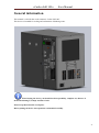
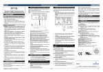
«Carbo-chill 100»
User Manual
USER MANUAL
Cooler saturator
Carbo-chill 100
Written by: PJSC UKSNAB
1a, Severnaya st.
96000, Krasnoperekopsk
Crimea, Ukraine
Published by: UBC Group
www.beer-co.com
200.00.000.00 РЭ User Manual
«Carbo-chill 100»
User Manual
Contents
1. General information
Notes and Cautions
p.3
p.4
2. Part 1.Technical specifications
p.5
3. Part 2. Functional description
Cooling device
Start up
p.6
4. Part 3. Installation
Unpacking
Tools
Placement and installation
Working order
Safety requirements
Air inlet
Installation site
Electrical installation
p.7
p.8
5. Part 4. Cleaning and Maintenance
General
Monthly
Maintenance
Storage and transportation
Storage without package
p.12
6. Part 5. Trouble shooting
p.14
7. Part 6. Spare parts
p.16
8. Appendix A. Electrical diagram
p.17
9. Appendix B. Wiring diagram
p.18
p.9
p.10
p.11
p.14
2
«Carbo-chill 100»
User Manual
General information
This manual is valid for the cooler saturator “Carbo-chill 100”.
This device is intended for cooling and carbonation of drinking water.
When buying the device you should check its operability, complete set, absence of
mechanical damages, stamps and date of sale.
Please keep this manual in a safe place.
Before putting the device into operation read manual carefully.
3
«Carbo-chill 100»
User Manual
Notes and Cautions!
Throughout the manual cautions and notes are written in bold like the example below:
Don’t turn the unit upside down or place it at one of the sides.
Explanation
Symbol
Meaning
Explanation
Note
The operator should observe and/or act according to the
information in order to obtain the best possible function of
the equipment.
Caution
The operator must observe and/or act according to the
information in order to avoid any mechanical or electrical
damage to the equipment or any personnel injury.
Installation
• It is the responsibility of the owner and operator/s of this equipment that the installation is made in
accordance with local regulations and safety requirements.
• Service and repair must be performed only by service technicians who are trained in servicing the
equipment. The installation procedure and requirements are described further this manual.
• The manufacturer cannot be responsible for any damage caused by incorrect installation of this cooler.
• The unit must be installed and connected in the ventilated place with nothing placed at least 50 cm
distance from both sides of the unit.
Repair and maintenance of the closed system for refrigerant and handling of refrigerants
must be done only by a company authorized in handling refrigerants.
4
«Carbo-chill 100»
User Manual
Part 1: Technical specifications
Name of characteristic
Nominal voltage
Frequency
Current consumption, not less
Operating temperatures
Refrigerant R 134а
Net weigh
Dimensions (without package), not less
Width
Length
Height
Cooler capacity at Δt*= 16 0C
Water tank capacity, not less
Ice bank
Ice forming at water t = 24 °C
Minimal outlet temperature
Number of coils
Compressor power
Compressor cooling capacity t = - 10 °C
tk = + 45 °C
Carbonator pump:
capacity
capacity at 6,9 bar
Submersible pump:
capacity
Water lifting
Unit
V
Hz
A
ºС
kg
lb
kg
Nominal
115
60
4,5
18 - 32
0,140
0,309
34
339
mm
l/h
l
kg
h
ºС
it
HP
W
kkаl/h
l/h
l/h
m
477
477
40
10,5
4,4
2
2-6
1
1/4
432
371
318
192
870
1,1
Δt* - the difference between inlet and outlet water or soft drinks temperature
5
«Carbo-chill 100»
User Manual
Part 2: Functional description
Cooling device
Cooler is a metallic construction of a box type with detachable walls and removable cover.
On the front side of the cooler body are:
- switch of the cooler;
- indicator lamp water level of carbonator bowl;
- fittings for connecting of the tap water and СО2 cylinder;
- digital thermometer display for a visual control of the water temperature in the bath;
- fittings for connecting of the flowing cooled water and cooled saturated water;
Inside of the cooler body are:
- refrigerating unit of a compressive type for the water cooling, component parts of which are
compressor, air condenser, filter-dehydrator, evaporator, interconnected by the copper pipes
through the soldered connections, forming the sealed system filled with the ozone-friendly
refrigerant- R134a.
- plastic bath isolated outside by the heat insulation from polyurethane foam and in which there are
evaporator, heat-exchanger, carbonator bowl, mechanical thermostat sensor serving to maintain a
defined thickness of the ice in the bath, submersible pump.
- carbonator pump.
The functioning of the cooler is based on the principle that the vapors of the coolant, boiling in the
refrigerating unit evaporator, take the heat away from the water in the bath necessary for its boiling.
Being cooled the water turns into the ice on the evaporator tubes. The thickness of the ice field is
controlled by the position sensor thermostat mounted on the evaporator coils. The thermostat should be
set to position "7".
While pouring the water becomes cooled passing through the heat exchanger and saturated with carbon
dioxide in the bulb-carbonator. The water temperature at the outlet depends upon its temperature at the
inlet to the heat exchanger. While the water pouring the ice field runs out. After the complete exhaustion
of the ice field the water temperature at the outlet begins to rise (if the thermometer shows the
temperature higher than 40F, it is not recommended to pour the saturated water because the degree of
carbonization sharply diminishes).
The hydraulic circuit saturator includes bypass line, the main element is a valve. Change
the position of the valve is not recommended, because it is configured for a given pressure of
carbonization (up to 3 bar).
Start up
Before starting up the equipment, make installation according to the descriptions in Part 3 of this manual.
The optimum temperature range for cooling operation is from 18 to 32 ºС. The cooler should be located
in a spot with a very good air circulation. In event of the cooler relocation from a cold place to a warm
one, the cooler may be switched on in no less than 1,5 – 2 hours.
6
«Carbo-chill 100»
User Manual
Part 3: Installation
Don’t turn the unit upside down or place it at one of the sides. If the unit has by accident
been turned upside down, it must rest for 4 hours before starting it.
7
«Carbo-chill 100»
User Manual
Unpacking
Think about possible re-use of packaging material. Carefully unpack the cooler unit - do not turn it upside
down - and check that all parts are in good condition.
The inner lid and removable strap attached cooler self-tapping screws. Screws are the
transfer and can not be re-threading.
Tools
Standard tools are sufficient.
Placement and installation
For more effective power consumption we recommend to place the cooler far from heat sources and in
dry, ventilated facilities.
The cooler should be mounted on the firm and flat horizontal basis.
Air condenser and venting grids of the cooler should be always free for air access and circulation.
Minimal distance from venting grids to the cooler walls or barriers should be 20 cm.
Check compliance of power indexed at the cooler label with current power.
Check the electrical wiring for any possible insulation defects, absence of current-carrying parts locking.
Insert the plug of the cooler into the plug socket with earthing.
8
«Carbo-chill 100»
User Manual
Working order
1) To fill the cooler bathtub with the water (depending on the fulfillment through the neck of the lid,
through a removable strip on the inner lid), until it rises to the overflow level.
2) To connect the output lines of the cooled water and cooled carbonized water to the column (it is
necessary to connect both lines);
3) To connect the cooler to the СО2 cylinder with the pressure at the manometer in 3 bar (the
maximum pressure of the carbonic acid supplied to the cooler should not exceed 3 bar).
4) To connect the cooler to the water supply. For normal work of the cooler the tap water pressure
should be in the range 2-3 bar. Previously you can use the filter for the tap water cleaning.
5) To check the position of the thermostat (must be set to "7").
6) To check the connection of the submersible pump and carbonization pump.
7) To connect the device into the network.
8) To switch the cooler on (a green button on the front panel).
9) Filling begin after the formation of ice bank (2 hours at ambient temperature 24 °C).
10) The optimum temperature for the saturation is 31 – 40F (the temperature value is shown on the
display of the electronic thermometer on the device front panel). If you exceed this temperature was
chilled bottled water saturated is not recommended.
9
«Carbo-chill 100»
User Manual
Safety requirements
The cooler has the first class power safety (including earthing).
Before connection of the cooler to power grid make sure that:
- Parameters supply main is nominal: 115V, 60Hz;
- Power cable and plug are not damaged.
The cooler should be connected with power grid only with earthing. Check it before starting the
installation process.
With the advent of signs of wiring locking (coverlet tingling while touching the metal parts of the cooler)
the Customer should disconnect the cooler from the power grid and call for the technician for defects
elimination.
The Customer should not use the cooler in facilities of high danger level with one or several conditions of
the following:
- deviation from nominal voltage 115 V over the allowed range: + 10% - 15%. ;
- extra dampness or dust (air humidity is more than 80%, when ceiling, walls, floor and other
things in the room are covered with moisture);
- air temperature is above 32 ºC;
- chemically active medium, which critically influents on electric insulation and current-carrying
parts of electric equipment;
- current-carrying floors.
The Customer should not touch the frame of running coolers.
The coolers should be disconnected from the power grid only within the following reasons:
•
Sanitary processing;
•
Replacement of the cooler;
•
Other operations connected with servicing of cooler
In case of network cord damage and to avoid the danger of current injury the Customer should not make
the cord replacement by himself but call for the technical specialist.
The Producer is not responsible for possible damages the personnel or equipment in case of ignoring of
above mentioned requirements.
10
«Carbo-chill 100»
User Manual
Air inlet
For efficient operation, free space around the unit must be min. 20 cm.
All air inlets/outlets on the unit must not be blocked by waste chemical containers etc.
It is of upmost importance to ensure free circulation of air around the cooler.
Otherwise the unit will be too hot which consequently will result in reduced efficiency and risk of
unnecessary operating problems.
Installation site
• This cooler unit is for indoor and outdoor installation.
Electrical installation
Installation should be made according to local regulations.
Please see the Electrical Diagram in the Appendix A.
11
«Carbo-chill 100»
User Manual
Part 4: Cleaning and maintenance
General
Always unplug the unit from power supply before carrying out any cleaning or
maintenance procedures etc.
Repair and maintenance of the closed system for refrigerant and handling of refrigerants must be
done only by a company authorized in handling refrigerants.
Never use any other refrigerants than specified for this unit.
Refrigerant type is specified in Part 1.
Never turn the unit upside down or place it on one of the sides. If the unit by
accident has been turned upside down, let it rest 4 hours before starting it.
The cooler unit is designed to operate with minimum of maintenance. Following the directions in this
chapter will ensure that your equipment will operate efficiently. Performing cleaning and maintenance on
a schedule basis minimizes the chance of equipment failure and loss of processing quality.
The cleaning of inside and outside surfaces of the cooler should be provided as required but not
rare than once per month. Pull the plug out of the socket before starting the cleaning.
Monthly
• Make sure to switch off/disconnect the power supply to the cooler unit.
• Clean all external surfaces using a moist cloth.
• Remove all dust and fluff from all of the ventilation slots and the condenser fins with a stiff (non-metal)
brush. Vacuum the debris from the fins.
Care should be taken not to damage the fins of the condenser.
• Inspect visible parts for damage. If any damage is found that impedes normal operation, contact your
local service centre.
• Visually check hoses and hose connections for leaks and damages. Tighten any loose
connectors.
• After cleaning and inspection make sure that the cooler top cover is secured
Maintenance
To avoid increasing of consumed power and to provide its undisturbed operation the customer should
follow these directions:
- do not block up the cooler frame, venting grids ensuring free air circulation;
- clean air condenser of dust and soiling;
- keep the cooler in clean condition.
12
«Carbo-chill 100»
User Manual
If you need access to a modular bay to observe the following procedure:
1) Remove the screw that secures the lid.
2) Remove the screw connecting the removable side wall to the platform.
3) Open the latch and remove the wall.
13
«Carbo-chill 100»
User Manual
Storage and Transportation
The cooler should be stored in the package.
The cooler should be stored in the dry ventilated facility with relative humidity not higher than 80%.
The cooler should be transported only in vertical position.
Storage without package.
The cooler should be stored in dry damp-proof facility. Stacking without package is forbidden.
The cooler should be transported in a package by any type of transport only in vertical position. It’s not
recommended to replace the cooler inside transport.
Part 5: Trouble Shooting
Before starting trouble shooting
If the cooler unit does not work according to the description in this manual, the following pages are meant
as a help for you.
Read them carefully and find the paragraph that corresponds to your problem.
Always unplug the cooler unit from power supply before carrying out any repair, cleaning
or maintenance procedures etc.
Never open the closed system with refrigerant. If necessary, this must be done only by a company
authorized in handling refrigerants.
Always remember that the cooling unit requires air. Dirty or blocked condenser fins or
aperture grills or lack of air space around the cooler can result in part or total failure of the unit.
Never turn the unit upside down or place it on one of its sides. If the unit by accident has been
turned upside down, let it rest for 4 hours before starting it.
If the equipment should fail to function please check as suggested below and correct if possible.
14
«Carbo-chill 100»
Symptom
The cooler is connected with
power but does not work.
User Manual
Probable Cause
Remedy
There is no power in the main
Check the power in the socket by
means of tester
The plug is not fully connected
with the socket
Check and provide plug’s contact
with the socket
The thermoregulator knob is
fixed at «0»
Fix the knob at extreme right
position
Refrigerant is not available in
system.
Refrigerant cannot pass through
capillary.
Compressor valve is out of order
Cooler cannot be started.
No voltage
The temperature sensor is
Compressor works
broken.
continuously without
switching. Product in the heat
exchanger is overfrozen.
Noise while cooler is
running.
The indicator lamp of the
water level is burning
Not enough carbonated water
- Some part of the cooling unit
contacts with the cooler frame.
- Compressor mounting on
shock damper is broken.
- Fan baffles contact with the air
condenser.
Call for the technician of service
company.
Check mains voltage availability.
Call for the technician of service
company.
Call for the technician of service
company.
Call for the technician of service
company
No water in carbonator bowl
Check the pump connection
(plastic connector).
Call for the technician of service
Carbonation pump is not working company
The water is not being piped
Not fed carbon dioxide.
Insufficient system pressure
The water temperature is greater
than 40F
Check the connection of the
water-pipe supply
Check the connection of carbon
dioxide
Look at the display thermometer.
Stop pouring until the
temperature will drop below 40F
15
«Carbo-chill 100»
User Manual
Part 6: Spare Parts
Part No.
Specification
1
"EMBRACO" NE 6160Z
Compressor
2
"LU-VE" STVF 75
Condenser
3
"Shurflo" 8035-963-239
Carbonator pump
4
Maxi-Jet 900
Submersible pump
5
"RANCO" K50H2005003
Thermostat
6
GICAR NRL30/2E/2R/F
Level controller
7
"Dixell" XT11S-4000N
Digital thermometer
16
«Carbo-chill 100»
User Manual
Appendix A: Electrical Diagram
17
«Carbo-chill 100»
User Manual
Appendix B: Wiring Diagram
18