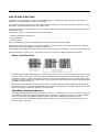
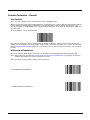
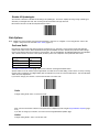
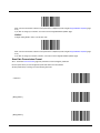
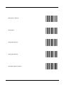
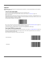
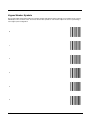
Download Bluetooth Ring Scanner User's Guide

Transcript
8650 Bluetooth Ring Scanner
User’s Guide
Disclaimer
Honeywell International Inc. (“HII”) reserves the right to make changes in specifications and other information contained in this
document without prior notice, and the reader should in all cases consult HII to determine whether any such changes have been
made. The information in this publication does not represent a commitment on the part of HII.
HII shall not be liable for technical or editorial errors or omissions contained herein; nor for incidental or consequential damages
resulting from the furnishing, performance, or use of this material.
This document contains proprietary information that is protected by copyright. All rights are reserved. No part of this document
may be photocopied, reproduced, or translated into another language without the prior written consent of HII.
© 2008-2015 Honeywell International Inc. All rights reserved.
Web Address: www.honeywellaidc.com
Trademarks
RFTerm is a trademark or registered trademark of EMS Technologies, Inc. in the United States and/or other countries.
The Bluetooth® word mark and logos are owned by the Bluetooth SIG, Inc.
Symbol® is a registered trademark of Symbol Technologies. MOTOROLA, MOTO, MOTOROLA SOLUTIONS and the Stylized M
Logo are trademarks or registered trademarks of Motorola Trademark Holdings, LLC and are used under license.
Wavelink®, the Wavelink logo and tagline, Wavelink Studio™, Avalanche Management Console™, Mobile Manager™, and
Mobile Manager Enterprise™ are trademarks of Wavelink Corporation, Kirkland.
Other product names or marks mentioned in this document may be trademarks or registered trademarks of other companies
and are the property of their respective owners.
Patents
For patent information, please refer to www.hsmpats.com.
Table of Contents
Chapter 1 - Bluetooth Ring Scanner Agency Compliance
Label Locations ....................................................................................................................1-1
Laser Label ..........................................................................................................................1-2
Laser Safety Statement .......................................................................................................1-2
Beam Divergence ................................................................................................................1-3
FCC Part 15 Statement........................................................................................................1-3
RF Exposure Statement.......................................................................................................1-4
Canadian Compliance..........................................................................................................1-4
EU – Note ............................................................................................................................1-4
CE Mark ...............................................................................................................................1-4
Bluetooth ..............................................................................................................................1-5
Honeywell Scanning & Mobility Product Environmental Information....................................1-5
Dealer License - Republic of Singapore ..............................................................................1-5
Chapter 2 - Getting Started
Overview ..............................................................................................................................2-1
About this Guide ..................................................................................................................2-1
Out of the Box ......................................................................................................................2-1
Initial Setup ..........................................................................................................................2-2
Hardware Setup .............................................................................................................2-2
Software Setup...............................................................................................................2-2
Components.........................................................................................................................2-3
Bluetooth Ring Scanner Before Assembly .....................................................................2-3
Bluetooth Module ...........................................................................................................2-3
Ring Imager / Ring Scanner...........................................................................................2-4
Assembly .............................................................................................................................2-5
Determine Left or Right Orientation ...............................................................................2-5
Insert Module in Sleeve..................................................................................................2-5
Connecting the Ring Device Cable ................................................................................2-6
Module Battery Help.......................................................................................................2-7
Adjusting the Ring Device Strap ..........................................................................................2-7
Status LEDs and Beep Indicators ........................................................................................2-7
Bluetooth Module Status LED and Beep Indicators .............................................................2-8
Bluetooth Ring Device LED .................................................................................................2-9
Rebooting the Bluetooth Module........................................................................................2-10
Suspend .......................................................................................................................2-10
Reboot..........................................................................................................................2-10
Reset............................................................................................................................2-10
Battery................................................................................................................................2-10
Battery Low Condition ..................................................................................................2-10
Pairing Bluetooth Devices ..................................................................................................2-10
Bluetooth MAC ID Bar Code Label ..............................................................................2-11
Connecting to a Generic Bluetooth Device ..................................................................2-12
Clearing Paired Status .......................................................................................................2-12
Removing / Replacing the Trigger Module.........................................................................2-12
i
Remove Finger Strap Assembly .................................................................................. 2-12
Replace Trigger Module .............................................................................................. 2-12
How To Scan a Bar Code.................................................................................................. 2-14
Scan a Linear Bar Code .............................................................................................. 2-14
Good Read / Bad Read Indicators............................................................................... 2-14
Factors That May Impact Scanner Performance............................................................... 2-15
Bar Code Scanning Help ................................................................................................... 2-15
Miscellaneous Programmable Bar Codes ......................................................................... 2-16
Beep After Good Decode............................................................................................. 2-16
Beeper Frequency Adjustment .................................................................................... 2-16
Beep on <BEL> ........................................................................................................... 2-16
Beeper Tone / Beeper Volume .................................................................................... 2-16
Event Reporting ........................................................................................................... 2-16
LED Mode.................................................................................................................... 2-16
Return to Factory Default Settings............................................................................... 2-17
Chapter 3 - Bluetooth Module Programming Bar Codes
Introduction.......................................................................................................................... 3-1
Preparation .......................................................................................................................... 3-1
Module Programming Bar Codes ........................................................................................ 3-1
Restore Factory Defaults ............................................................................................... 3-2
Module Firmware Version.............................................................................................. 3-2
Pairing Status ................................................................................................................ 3-3
Suspend Timeout........................................................................................................... 3-4
Beep on Reconnect ....................................................................................................... 3-5
Reconnect Interval Timeout........................................................................................... 3-6
Reconnect Timeout........................................................................................................ 3-7
Role Switching ............................................................................................................... 3-8
Authentication ................................................................................................................ 3-9
Encryption...................................................................................................................... 3-9
Beep Volume ............................................................................................................... 3-10
Ring Imager Focus Mode ............................................................................................ 3-11
Enter Friendly Name or PIN Code ............................................................................... 3-12
PIN Code ............................................................................................................... 3-12
Friendly Name ....................................................................................................... 3-13
Numbers ................................................................................................................ 3-14
Lowercase Letters ................................................................................................. 3-16
Uppercase Letters ................................................................................................. 3-20
Chapter 4 - 1D Laser Scanner Programming Bar Codes
Introduction.......................................................................................................................... 4-1
Aiming Modes...................................................................................................................... 4-2
SE955 Ring Scanner ..................................................................................................... 4-2
Prefix / Suffix ....................................................................................................................... 4-2
Set Default Parameter ................................................................................................... 4-6
Scanner Parameters – General........................................................................................... 4-7
Aim Duration .................................................................................................................. 4-7
ii
Bi-Directional Redundancy ............................................................................................ 4-7
Disable All Symbologies ................................................................................................ 4-8
Data Options........................................................................................................................ 4-8
Prefix and Suffix............................................................................................................. 4-8
Prefix........................................................................................................................ 4-8
Suffix 1..................................................................................................................... 4-8
Suffix 2..................................................................................................................... 4-9
Scan Data Transmission Format ................................................................................... 4-9
Transmit Code ID Character........................................................................................ 4-11
Transmit No Code ID Character ............................................................................ 4-11
Transmit Symbol Code ID Character..................................................................... 4-11
Transmit AIM Code ID Character .......................................................................... 4-12
Laser On Time ............................................................................................................. 4-14
Linear Code Type Security Level (Redundancy Level) ............................................... 4-15
Parameter Pass Through............................................................................................. 4-16
Parameter Scanning .................................................................................................... 4-16
Power Mode................................................................................................................. 4-17
Scan Angle (SE955 only)............................................................................................. 4-17
Simple Serial Interface (SSI) Options .......................................................................... 4-18
SSI Defaults........................................................................................................... 4-18
Beep on BEL.......................................................................................................... 4-18
Baud Rate.............................................................................................................. 4-18
Decode Data Packet Format ................................................................................. 4-19
Host Character Time-out ....................................................................................... 4-19
Intercharacter Delay .............................................................................................. 4-20
Software Handshaking........................................................................................... 4-22
Stop Bit Select ....................................................................................................... 4-23
Time-out Between Decodes, Same Symbol ................................................................ 4-23
Transmit “No Read / Decode” Message ...................................................................... 4-24
Trigger Mode ............................................................................................................... 4-25
Scanner Parameters – Bar Code Type Specific................................................................ 4-26
Chinese 2 of 5.............................................................................................................. 4-26
Codabar ....................................................................................................................... 4-27
CLSI Editing........................................................................................................... 4-27
NOTIS Editing........................................................................................................ 4-28
Set Lengths for Codabar........................................................................................ 4-28
One Discrete Length (Parameter L1) .............................................................. 4-28
Two Discrete Lengths (Parameter L2) ............................................................ 4-29
Length Within Range ...................................................................................... 4-29
Any Length ...................................................................................................... 4-29
Code 11 ....................................................................................................................... 4-30
Set Lengths for Code 11........................................................................................ 4-30
One Discrete Length (Parameter L1) .............................................................. 4-30
Two Discrete Lengths (Parameter L2) ............................................................ 4-30
Length Within Range ...................................................................................... 4-31
Any Length ...................................................................................................... 4-31
Code 11 Check Digit Verification ........................................................................... 4-32
Transmit Code 11 Check Digits ............................................................................. 4-32
iii
Code 128 ..................................................................................................................... 4-33
GS1-128 (formerly UCC/EAN-128)........................................................................ 4-33
ISBT-128................................................................................................................ 4-34
Lengths for Code 128 ............................................................................................ 4-34
Code 39 ....................................................................................................................... 4-35
Code 39 Check Digit Verification ........................................................................... 4-35
Code 32 Prefix ....................................................................................................... 4-36
Convert Code 39 to Code 32 ................................................................................. 4-36
Code 39 Full ASCII Conversion............................................................................. 4-37
Set Lengths for Code 39........................................................................................ 4-37
Code 39 One Discrete Length (Parameter L1) ............................................... 4-37
Code 39 Two Discrete Lengths (Parameter L2) ............................................. 4-38
Code 39 Length Within Range ........................................................................ 4-38
Code 39 Any Length ....................................................................................... 4-38
Transmit Code 39 Check Digit............................................................................... 4-39
Trioptic Code 39 .................................................................................................... 4-39
Code 93 ....................................................................................................................... 4-40
Set Lengths for Code 93........................................................................................ 4-40
One Discrete Length (Parameter L1) .............................................................. 4-40
Two Discrete Lengths (Parameter L2) ............................................................ 4-41
Length Within Range ...................................................................................... 4-41
Any Length ...................................................................................................... 4-41
Discrete 2 of 5.............................................................................................................. 4-42
Set Lengths for Discrete 2 of 5 .............................................................................. 4-42
One Discrete Length (Parameter L1) .............................................................. 4-42
Two Discrete Lengths (Parameter L2) ............................................................ 4-43
Length Within Range ...................................................................................... 4-43
Any Length ...................................................................................................... 4-43
Interleaved 2 of 5 ......................................................................................................... 4-44
I 2 of 5 Check Digit Verification.............................................................................. 4-44
Convert I 2 of 5 to EAN-13..................................................................................... 4-45
Set Lengths for I 2 of 5 .......................................................................................... 4-45
One Discrete Length (Parameter L1) .............................................................. 4-45
Two Discrete Lengths (Parameter L2) ............................................................ 4-46
Length Within Range ...................................................................................... 4-46
Any Length ...................................................................................................... 4-46
Transmit I 2 of 5 Check Digit ................................................................................. 4-47
MSI Plessey................................................................................................................. 4-48
MSI Plessey Check Digit Algorithm ....................................................................... 4-48
MSI Plessey Check Digits...................................................................................... 4-49
Set Lengths for MSI Plessey ................................................................................. 4-49
One Discrete Length (Parameter L1) .............................................................. 4-49
Two Discrete Lengths (Parameter L2) ............................................................ 4-50
Length Within Range ...................................................................................... 4-50
Any Length ...................................................................................................... 4-50
Transmit MSI Plessey Check Digit ........................................................................ 4-51
UPC/EAN..................................................................................................................... 4-52
UPC-A.................................................................................................................... 4-52
iv
UPC-E.................................................................................................................... 4-52
UPC-E1.................................................................................................................. 4-53
EAN-8 .................................................................................................................... 4-53
EAN-13 .................................................................................................................. 4-54
Bookland EAN ....................................................................................................... 4-54
Bookland ISBN Format .......................................................................................... 4-55
Check Digits........................................................................................................... 4-55
Transmit UPC-A Check Digit .......................................................................... 4-55
Transmit UPC-E Check Digit .......................................................................... 4-56
Transmit UPC-E1 Check Digit ........................................................................ 4-56
Conversions........................................................................................................... 4-57
Convert UPC-E to UPC-A ............................................................................... 4-57
Convert UPC-E1 to UPC-A ............................................................................. 4-57
Convert EAN-8 to EAN-13 Type ..................................................................... 4-58
Preambles.............................................................................................................. 4-59
UPC-A Preamble ............................................................................................ 4-59
UPC-E Preamble ............................................................................................ 4-60
UPC-E1 Preamble .......................................................................................... 4-61
Supplementals ....................................................................................................... 4-62
Decode UPC/EAN Supplementals .................................................................. 4-62
User-Programmable Supplementals ............................................................... 4-64
Decode UPC/EAN Supplemental Redundancy .............................................. 4-64
EAN-8 Zero Extend................................................................................................ 4-65
UCC Coupon Extended Code................................................................................ 4-65
UPC/EAN Security Level ....................................................................................... 4-66
GS1 DataBar (RSS) Codes ......................................................................................... 4-67
GS1 DataBar Omnidirectional (RSS-14) ............................................................... 4-67
GS1 DataBar Limited (RSS-Limited) ..................................................................... 4-67
GS1 DataBar Expanded (RSS-Expanded) ............................................................ 4-68
Convert GS1 DataBar (RSS) to UPC/EAN ............................................................ 4-68
Appendix............................................................................................................................ 4-69
Laser On Time (superseded)....................................................................................... 4-69
Scan Angle (SE955 only) superseded......................................................................... 4-69
Set Lengths for I 2 of 5 (superseded) .......................................................................... 4-70
One Discrete Length (Parameter L1)..................................................................... 4-70
Two Discrete Lengths (Parameter L2)................................................................... 4-70
Length Within Range ............................................................................................. 4-71
Any Length............................................................................................................. 4-71
Keypad Number Symbols.................................................................................................. 4-72
Chapter 5 - 2D Laser Imager Programming Bar Codes
Introduction.......................................................................................................................... 5-1
Set All Defaults/Cancel Bar Codes...................................................................................... 5-5
Enable / Disable Parameter Scanning................................................................................. 5-6
Imager Parameters – General ............................................................................................. 5-6
Decode Session Timeout............................................................................................... 5-6
Decode Aiming Pattern.................................................................................................. 5-7
Decoding Autoexposure ................................................................................................ 5-7
v
Decoding Illumination .................................................................................................... 5-8
Focus Mode ................................................................................................................... 5-9
LED Illumination........................................................................................................... 5-10
Operational Mode ........................................................................................................ 5-11
Power Mode................................................................................................................. 5-12
Presentation Mode Session Timeout........................................................................... 5-12
Time Delay to Low Power Mode.................................................................................. 5-13
Time-out between Decodes, Same Symbol ................................................................ 5-14
Trigger Modes.............................................................................................................. 5-15
Report Version............................................................................................................. 5-16
Transmit Code ID Character........................................................................................ 5-16
Transmit No Code ID Character ............................................................................ 5-16
Transmit Symbol Code ID Character..................................................................... 5-17
Transmit AIM Code ID Character .......................................................................... 5-18
Prefix / Suffix Values.................................................................................................... 5-22
Suffix 1................................................................................................................... 5-22
Suffix 2................................................................................................................... 5-22
Scan Data Transmission Format ................................................................................. 5-23
Transmit “No Read” Message...................................................................................... 5-25
UPC/EAN........................................................................................................................... 5-26
UPC-A.......................................................................................................................... 5-26
UPC-E.......................................................................................................................... 5-26
UPC-E1........................................................................................................................ 5-27
EAN-8/JAN-8 ............................................................................................................... 5-27
EAN-13/JAN-13 ........................................................................................................... 5-28
Bookland EAN ............................................................................................................. 5-28
Bookland Format ......................................................................................................... 5-29
Decode UPC/EAN/JAN Supplementals (2 and 5 digits) .............................................. 5-29
UPC/EAN/JAN Supplemental Redundancy................................................................. 5-31
Transmit UPC-A Check Digit ....................................................................................... 5-31
Transmit UPC-E Check Digit ....................................................................................... 5-32
Transmit UPC-E1 Check Digit ..................................................................................... 5-32
UPC-A Preamble ......................................................................................................... 5-33
UPC-E Preamble ......................................................................................................... 5-34
UPC-E1 Preamble ....................................................................................................... 5-35
Convert UPC-E to UPC-A............................................................................................ 5-36
Convert UPC-E1 to UPC-A.......................................................................................... 5-36
EAN-8/JAN-8 Extend ................................................................................................... 5-37
UCC Coupon Extended Code...................................................................................... 5-37
Code 128 ........................................................................................................................... 5-38
UCC/EAN-128 ............................................................................................................. 5-38
ISBT-128...................................................................................................................... 5-39
Code 39 ....................................................................................................................... 5-39
Trioptic Code 39 .......................................................................................................... 5-40
Convert Code 39 to Code 32 ....................................................................................... 5-40
Code 32 Prefix ............................................................................................................. 5-41
Set Length(s) for Code 39 ........................................................................................... 5-42
One Discrete Length (Parameter L1)..................................................................... 5-42
vi
Two Discrete Lengths (Parameter L2)................................................................... 5-42
Length Within Range ............................................................................................. 5-42
Any Length............................................................................................................. 5-43
Code 39 Check Digit Verification ................................................................................. 5-43
Transmit Code 39 Check Digit..................................................................................... 5-44
Code 39 Full ASCII Conversion................................................................................... 5-44
Code 93 ............................................................................................................................. 5-45
Set Lengths for Code 93.............................................................................................. 5-45
One Discrete Length (Parameter L1)..................................................................... 5-45
Two Discrete Lengths (Parameter L2)................................................................... 5-46
Length Within Range ............................................................................................. 5-46
Any Length............................................................................................................. 5-46
Code 11 ............................................................................................................................. 5-47
Set Lengths for Code 11.............................................................................................. 5-47
One Discrete Length (Parameter L1)..................................................................... 5-47
Two Discrete Lengths (Parameter L2)................................................................... 5-48
Length Within Range ............................................................................................. 5-48
Any Length............................................................................................................. 5-48
Code 11 Check Digit Verification ................................................................................. 5-49
Transmit Code 11 Check Digits ................................................................................... 5-49
Interleaved 2 of 5 (ITF) ...................................................................................................... 5-50
Set Lengths for I 2 of 5 ................................................................................................ 5-50
One Discrete Length (Parameter L1)..................................................................... 5-50
Two Discrete Lengths (Parameter L2)................................................................... 5-51
Length Within Range ............................................................................................. 5-51
Any Length............................................................................................................. 5-51
I 2 of 5 Check Digit Verification.................................................................................... 5-52
Transmit I 2 of 5 Check Digit ....................................................................................... 5-52
Convert I 2 of 5 to EAN 13........................................................................................... 5-53
Discrete 2 of 5 (DTF) ......................................................................................................... 5-53
Set Lengths for Discrete 2 of 5 .................................................................................... 5-54
Two Discrete Lengths (Parameter L2)................................................................... 5-54
Length Within Range ............................................................................................. 5-55
Any Length............................................................................................................. 5-55
Codabar............................................................................................................................. 5-56
CLSI Editing................................................................................................................. 5-56
NOTIS Editing.............................................................................................................. 5-57
Set Lengths for Codabar.............................................................................................. 5-57
One Discrete Length (Parameter L1)..................................................................... 5-57
Two Discrete Lengths (Parameter L2)................................................................... 5-58
Length Within Range ............................................................................................. 5-58
Any Length............................................................................................................. 5-58
MSI .................................................................................................................................... 5-59
Set Length(s) for MSI................................................................................................... 5-59
Two Discrete Lengths (Parameter L2)................................................................... 5-60
Length Within Range ............................................................................................. 5-60
Any Length............................................................................................................. 5-60
MSI Check Digits ......................................................................................................... 5-61
vii
Transmit MSI Check Digit ............................................................................................ 5-61
MSI Check Digit Algorithm........................................................................................... 5-62
Postal Codes ..................................................................................................................... 5-62
US Postnet................................................................................................................... 5-62
US Planet..................................................................................................................... 5-63
UK Postal..................................................................................................................... 5-63
Transmit UK Postal Check Digit ............................................................................ 5-64
Japan Postal ................................................................................................................ 5-64
Australian Postal.......................................................................................................... 5-65
Dutch Postal ................................................................................................................ 5-65
Transmit US Postal Check Digit .................................................................................. 5-66
4 State Postal .............................................................................................................. 5-66
GS1 DataBar (RSS)..................................................................................................... 5-67
GS1 DataBar Omnidirectional (RSS-14) ..................................................................... 5-67
GS1 DataBar Limited (RSS Limited) ........................................................................... 5-67
GS1 DataBar Expanded (RSS Expanded) .................................................................. 5-68
Convert GS1 DataBar (RSS) to UPC/EAN .................................................................. 5-68
Composite ......................................................................................................................... 5-69
Composite CC-C.......................................................................................................... 5-69
Composite CC-A/B ...................................................................................................... 5-69
Composite TLC-39....................................................................................................... 5-70
UPC Composite Mode ................................................................................................. 5-70
2D Symbologies ................................................................................................................ 5-71
Aztec............................................................................................................................ 5-71
Aztec Inverse ............................................................................................................... 5-72
PDF417........................................................................................................................ 5-72
MicroPDF417............................................................................................................... 5-73
Code 128 Emulation .................................................................................................... 5-73
Data Matrix .................................................................................................................. 5-74
Data Matrix Inverse...................................................................................................... 5-74
Maxicode ..................................................................................................................... 5-75
MicroQR....................................................................................................................... 5-75
QR Code...................................................................................................................... 5-76
QR Inverse................................................................................................................... 5-76
Redundancy Level............................................................................................................. 5-77
Security Level .................................................................................................................... 5-79
Intercharacter Gap Size..................................................................................................... 5-80
Imager Keypad Number Symbols...................................................................................... 5-81
Chapter 6 - Firmware Upgrade
Introduction.......................................................................................................................... 6-1
Updating the Module Firmware ........................................................................................... 6-1
Firmware Update Help......................................................................................................... 6-2
Install BlueCore Device Update Wizard and Driver............................................................. 6-2
Chapter 7 - Decode Zones
Introduction.......................................................................................................................... 7-1
viii
Ring Laser ........................................................................................................................... 7-1
Ring Imager ......................................................................................................................... 7-2
PL4407 Near Focus Decode Distances......................................................................... 7-2
PL4407 Toggled Focus Decode Distances ................................................................... 7-3
PL4407 Decode Distances in Darkness ........................................................................ 7-3
Chapter 8 - Battery Chargers
Unpacking your Battery Charger ......................................................................................... 8-1
Introduction.......................................................................................................................... 8-1
Cautions and Warnings ....................................................................................................... 8-2
Battery Charger ............................................................................................................. 8-2
Lithium-Ion Battery Pack................................................................................................ 8-2
Charging Batteries............................................................................................................... 8-3
Eight Bay Battery Charger................................................................................................... 8-3
Front View...................................................................................................................... 8-3
Charging Pocket ............................................................................................................ 8-4
Footprint and Mounting Hole Location........................................................................... 8-4
Installation...................................................................................................................... 8-4
Assemble the Power Supply.................................................................................... 8-4
Setup ....................................................................................................................... 8-4
Inserting a Battery into the Charging Pocket ................................................................. 8-5
Removing the Battery from the Charging Pocket .......................................................... 8-5
Interpreting the Charging Pocket LEDs ......................................................................... 8-5
Charge Timer................................................................................................................. 8-6
Charging Pocket ............................................................................................................ 8-6
Inserting a Battery into the Charging Pocket ................................................................. 8-6
Removing the Battery from the Charging Pocket .......................................................... 8-7
Interpreting the Charging LED ....................................................................................... 8-7
Charge Timer................................................................................................................. 8-7
Battery Charger Help........................................................................................................... 8-8
Charger Cleaning, Storage and Service.............................................................................. 8-9
Cleaning......................................................................................................................... 8-9
Storage .......................................................................................................................... 8-9
Service........................................................................................................................... 8-9
Battery Cleaning, Storage and Service ............................................................................... 8-9
Cleaning......................................................................................................................... 8-9
Storage .......................................................................................................................... 8-9
Service......................................................................................................................... 8-10
Chapter 9 - Technical Specifications
Bluetooth Ring Scanner Module.......................................................................................... 9-1
Technical Specifications ................................................................................................ 9-1
Environmental Specifications......................................................................................... 9-1
Bluetooth Radio ............................................................................................................. 9-1
Bluetooth Ring Scanner Battery Charger ............................................................................ 9-1
Electrical ........................................................................................................................ 9-1
Temperature .................................................................................................................. 9-2
ix
Dimensions .................................................................................................................... 9-2
ASCII Character Equivalents............................................................................................... 9-2
Chapter 10 - Customer Support
Technical Assistance......................................................................................................... 10-1
Product Service and Repair............................................................................................... 10-1
Limited Warranty ............................................................................................................... 10-1
x
1
Bluetooth Ring Scanner Agency Compliance
Bluetooth Ring Scanner modules and ring bar code decoders meet or exceed the requirements of all applicable standards
organizations for safe operation. However, as with any electrical equipment, the best way to ensure safe operation is to operate
them according to the agency guidelines that follow. Read these guidelines carefully before using your Bluetooth Ring Scanner.
This documentation is relevant for the following models: 8650 series (8651, 8652, 8653, 8654) Bluetooth Ring Scanner.
Caution:
!
RISK OF EXPLOSION IF BATTERY IS REPLACED BY AN INCORRECT TYPE. The battery should be disposed
of by a qualified recycler or hazardous materials handler. Do not incinerate the battery or dispose of the battery
with general waste materials.
Label Locations
Left Side of Scanner head
Right Side of Scanner Head
Laser Safety Label
Compliance Label
Part Number and Serial Number Label
Bottom of Bluetooth Module
Battery
Compliance Label
Compliance Label
Bottom of Eight Bay Battery Charger
Compliance Label
Bottom of Single Bay Battery Charger
Compliance Label
1-1
Laser Label
If the following label is attached to your ring bar code decoder, it indicates the ring bar code decoder contains an engine with a
laser aimer:
Laser Safety Statement
This device has been tested in accordance with and complies with IEC60825-1:2007 and EN60825-1:2007). Complies with 21
CFR 1040.10 and 1040.11, except for deviations pursuant to Laser Notice No. 50, dated June 24, 2007.
LASER LIGHT, DO NOT STARE INTO BEAM, CLASS 2 LASER PRODUCT, 1.0 mW MAX OUTPUT: 630-680nM.
Laser Warnings
• Do not look into the laser’s lens.
• Do not stare directly into the laser beam.
• Do not remove the laser caution labels from the Bluetooth Ring Scanner ring bar code decoders.
• Do not connect the laser bar code aperture to any other device. The laser bar code aperture is certified for use with the
Blueooth Ring Scanner module only.
Caution:
!
1-2
Laser radiation when open. Read the caution labels. Use of controls, adjustments or performance of procedures
other than those specified herein may result in hazardous radiation exposure.
Beam Divergence
See dimension
of field below
Width of Field
20” 50.8 cm
15” 38.1 cm
10” 31.6 cm
5”
12.7 cm
0”
0 cm
5”
12.7 cm
10” 31.6 cm
15” 38.1 cm
20” 50.8 cm
0”
0 cm
5”
12.7 cm
10”
25.4 cm
15”
38.1 cm
20”
50.8 cm
25”
63.5 cm
30”
76.2 cm
35”
88.9 cm
40”
45”
101.6 cm 114.3 cm
Depth of Field
FCC Part 15 Statement
The BT Module in the BTRS terminal has been tested and found to comply with the limits for a Class B digital device, pursuant
to Part 15 of the FCC Rules.
These limits are designed to provide reasonable protection against harmful interference in a residential installation.
This equipment generates, uses and can radiate radio frequency energy and, if not installed and used in accordance with the
instructions, may cause harmful interference to radio communications.
1-3
RF Exposure Statement
The BlueMod+B20 in the BTRS contains a portable modular transmitter. The max. output power of 10mW is well below the
FCC limit of 60mW/f(GHZ) = 60mW/2,4 = 25mW. Therefore no restrictions apply for the use of the BlueMod+B20 close to the
human body.
Caution: Any changes or modifications made not expressly approved by Honeywell may void the BT Module FCC authorization
to operate this equipment
Canadian Compliance
This ISM device complies with Canadian RSS-210.
Operation is subject to the following conditions:
1. This device may not cause harmful interference.
2. This device must accept any interference received, including interference that may cause undesired operation.
This Class B digital apparatus complies with Canadian ICES-003.
IMPORTANT NOTE:
Radiation Exposure Statement:
This equipment complies with IC radiation exposure limits set forth for an uncontrolled environment. End users must follow the
specific operating instructions for satisfying RF exposure compliance. To maintain compliance with IC RF exposure compliance
requirements, please follow operation instruction as documented in this manual.
EU – Note
This device is a 2.4 GHz wideband transmission system (transceiver), intended for use in all EU member states and EFTA
countries, except in France and Italy where restrictive use applies.
In Italy the end-user should apply for a license at the national spectrum authorities in order to obtain authorization to use the
device for setting up outdoor radio links and/or for supplying public access to telecommunications and/or network services.
This device may not be used for setting up outdoor radio links in France and in some areas the RF output power may be limited
to 10 mW EIRP in the frequency range of 2454 – 2483.5 MHz. For detailed information the end-user should contact the national
spectrum authority in France.
CE Mark
The CE marking indicates compliance with the following directives:
• 1995/5/EC R&TTE
• 2011/65/EU RoHS (Recast)
In addition, complies to 2006/95/EC Low Voltage Directive, when shipped with recommended power supply. European contact::
Hand Held Products Europe BV
Nijverheidsweg 9-13
5627 BT Eindhoven
The Netherlands
Honeywell shall not be liable for use of our product with equipment (i.e., power supplies, personal computers, etc.) that is not CE
marked and does not comply with the Low Voltage Directive.
1-4
Bluetooth
Class II
Honeywell Scanning & Mobility Product Environmental Information
Refer to www.honeywellaidc.com/environmental for the RoHS / REACH / WEEE information.
China RoHS
10
有毒有害物质名称及含量的标识 (Names and Content of Hazardous Substances or Elements)
部件名称 (Parts Name)
有毒有害物质或元素 (Toxic and Hazardous Substances or Elements)
铅 (Pb)
汞 (Hg)
镉 (Cd)
六价铬 (Cr6+)
多溴联苯 (PBB)
多溴二苯醚 (PBDE)
扫描模块 (Scanner Module)
x
o
o
o
o
o
印刷电路部件 (PCA)
x
o
o
o
o
o
外壳 (Housing)
x
o
o
o
o
o
连接线 (Cable)
x
o
o
o
o
o
o: 表示该有毒有害物质在该部件所有均质材料中的含量均在 SJ/T11363-2006 标准规定的限量要求以下 (Indicates that this toxic or hazardous substance contained in all of the
homogeneous materials for this part is below the limit requirement in China’s SJ/T11363-2006)
x: 表示该有毒有害物质至少在该部件的某一均质材料中的含量超出 SJ/T11363-2006 标准规定的限量要求 (Indicates that this toxic or hazardous substance contained in at least one of
the homogeneous materials for this part is above the limit requirement in China’s SJ/T11363-2006)
Dealer License - Republic of Singapore
1-5
1-6
2
Getting Started
Overview
This guide contains installation and configuration instructions for the Honeywell 8650 Bluetooth® Ring Scanner module, its
tethered ring scanner or ring imager and battery chargers.
Bar code decoding laser engines and imager engines are designed to read, decode and collect bar coded data from any nearby
compatible bar code label that is visible and on printed media.
The Bluetooth Ring Scanner consists of a ring decoder tethered to a sturdy, compact, mobile Bluetooth module and battery.
The module’s lightweight battery provides power to the ring decoder. The hand strap assembly is designed to be worn on the
back of either hand or on either wrist. The hook and loop fabric on the hand strap enables one-handed installation, adjustment
and removal of the hand strap.
Note: Bluetooth Ring Scanner Module paired data is stored in non-volatile memory in the module and data is saved over power
cycles. Paired devices automatically reconnect when power is applied.
The assembled Bluetooth Ring Scanner provides wireless communication with Bluetooth enabled Honeywell computers.
When the Bluetooth Ring Scanner Module pairs with another Bluetooth device, the Bluetooth Ring Scanner Module can send
serial data to the paired Bluetooth device.
The Bluetooth tethered ring scanner and tethered ring imager connectors are not interchangeable with other Honeywell mobile
devices that also use tethered ring scanners or ring imagers (i.e., Dolphin 70e Black in wearable sled, HX2 or HX3).
For information about other scanners, such as tethered ring scanners, scanners connected to a COM port or other Bluetooth
scanners, refer to www.honeywellaidc.com or the scanner manufacturer’s website.
About this Guide
This guide provides instruction for the end-user or system administrator to follow when setting up a new Bluetooth Ring Scanner
module and ring bar code decoder. This guide includes all programming bar codes and decode zones. Also included are setup
and use instruction for the Bluetooth Ring Scanner battery chargers.
Out of the Box
After you open the shipping carton verify it contains the following items:
• Bluetooth Ring Scanner module
• Ring bar code decoder
• Hand strap
• Rechargeable battery
• Quick Start Guide
If you ordered accessories for the Bluetooth Ring Scanner, verify they are also included with the order. Keep the original
packaging material in the event the Bluetooth Ring Scanner should need to be returned for service. For details, see Product
Service and Repair (page 10-1).
2-1
Initial Setup
Following are the steps you might take when setting up a new Bluetooth Ring Scanner. More instruction for each step is listed
later in this guide. Contact Customer Support (page 10-1) if you need additional help.
Accessory installation or removal should be performed on a clean, well-lit surface. When necessary, protect the work surface,
the Bluetooth Ring Scanner, and components from electrostatic discharge.
Note: The battery and ring device cables should not be exchanged or replaced in a dirty, harsh or hazardous environment.
When the ring tethers are disconnected, any dust or moisture that adheres to the tether connector can potentially cause
damage upon cable re-connection with the Bluetooth Module.
Hardware Setup
1. Determine which hand or wrist will contain the assembly.
1. Insert the Bluetooth Ring Scanner Module into the leather sleeve.
1. Thread ring cable connector through elastic loop on the appropriate side.
1. Connect the ring cable connector to the Bluetooth Ring Scanner Module.
1. Secure the module strap to the hand or wrist.
1. Connect the ring cable connector to the Module in the sleeve.
2. Insert a fully charged battery in the Bluetooth Ring Scanner Module and the Module powers up.
Software Setup
Set up the Module using an attached ring device and scan the following bar codes in Bluetooth Module Programming Bar
Codes (page 3-1):
• Enable / disable suspend timeout length
• Set the Beeper volume (Bluetooth module only, the rings do not emit sounds)
• Assign a Friendly Name
The Bluetooth Ring Scanner Module is ready to connect to a Bluetooth enabled host device.
2-2
Components
Bluetooth Ring Scanner Before Assembly
1. Module
2. Battery
3. Ring Scanner
4. Hand Strap Assembly
Bluetooth Module
1. Battery Compartment Latch
2. Speaker
3. LED
4. Input/Output Port: Ring device cable
connector
The Bluetooth ring scanner module does not have a power or on-off switch. When the battery is installed, the unit and its
accessories are On. Remove the battery to power down or turn off the unit.
2-3
Wrist Strap / Back of Hand Strap
1. Loops
2. Elastic ring cable protector
3. Bluetooth module sleeve
4. Hooks
Ring Imager / Ring Scanner
The ring imager can scan and decode 1D and 2D bar codes. The imager has three small illumination LEDs at the top of the
scan window or aperture.
The ring scanner can scan and decode 1D bar codes. The scanner does not have illumination LEDs.
After pairing with a Bluetooth enabled mobile computer, the ring device can then send the collected bar code data through
the module to the Bluetooth enabled mobile computer for processing. The Bluetooth Ring Scanner module emits good
read or bad read sounds based on the ring scan results. See Status LEDs and Beep Indicators (page 2-7) for an explanation of the LED and beep patterns emitted.
These ring decoding devices do not have the ability to emit a good read or bad read sound.
Ring Imager
Ring Scanner
Cable Connector
Do not touch, push against or brace your finger on the scan aperture at any time.
When new, there is a clear, tabbed protective film covering the ring decoder scan window. Remove and discard the clear,
tabbed protective film before scanning a bar code.
2-4
Assembly
Determine Left or Right Orientation
Determining whether to wear the module assembly on the left or right has a bearing on how the ring cable is attached to the
module and the ring to the finger. The ring cable should not cross over or under the hand.
Insert Module in Sleeve
There are two strap sizes to accommodate different sizes of wrists and hands. Choose the best size for a secure fit.
Insert the module in the module sleeve on the hand strap before securing the hand strap to the hand, if desired. The module is inserted in the sleeve with the LED facing upwards and visible through the circular cutout on the top of the module
sleeve.
Press the loops (on the top of the wrist strap) against the hooks (on the bottom of the wrist strap) to secure the strap to the
back of your hand or wrist.
2-5
Connecting the Ring Device Cable
1. Slip the ring cable connector through the elastic ring cable guide on the side of the Bluetooth module sleeve. The connector can be inserted from the left or the right.
1. Choose the same side as the finger that will be wearing the ring. The ring cable guides are designed to minimize excessive pulling or tugging on the scanner cable after the ring device is connected to the Bluetooth module.
2. Press the connector firmly into the I/O port. If there is a battery in the module the Bluetooth module LED illuminates and
the module beeps, signifying a ring cable I/O secure connection.
To remove the ring device cable, pinch and pull the cable connector straight up and away from the Bluetooth module.
Do not pull the cable when removing the ring device cable from the Bluetooth Ring Scanner module.
Inserting the Battery
The battery is spring loaded and will slide out when the battery cover latch is opened. As soon as the battery contacts lose
connection with the battery terminals in the battery bay, the Bluetooth module turns Off. When a battery is in the module,
the battery slides out of the battery bay far enough to be grasped and removed. Do not use a metal object, or extreme
force, to remove a battery from the module.
Note: A ring should be connected to the module before a battery is inserted in the module.
1. To open the battery bay door on the Bluetooth Ring Scanner module, orient the module so the LED on the module is
facing upward.
2. Slide the battery bay latch to the right. The battery bay cover springs open.
3. Insert a fully charged battery into the battery bay, making sure the battery terminals enter the battery bay at the right
side of the battery opening. Use the direction of the arrow on the battery label as a guide.
2-6
4. Press down on the battery until it is seated in the battery bay and close the battery bay hatch cover. Slide the battery
latch to the left to secure the battery in the Bluetooth Module.
5. The Bluetooth module beeps (short low tone beep, long low tone beep, long high tone beep) and the module LED
flashes.
Module Battery Help
Issue:
There is no beep or LED flash when inserting battery into the module.
Solution:
If a ring scanner is tethered to the Bluetooth module while a battery is being replaced and there is no beep or LED flash,
remove the battery, turn it over and reinsert, making sure the battery terminals enter the battery bay to the right. Slide the
battery bay latch to the left to secure the battery in the Bluetooth Module. If there is sufficient power in the battery, the Bluetooth module emits a series of beeps (short low tone beep, long low tone beep, long high tone beep) and the LED flashes.
Adjusting the Ring Device Strap
The ring device finger loop is located under the ring device. The ring device has a built-in quick disconnect designed for safety
hazards. The quick disconnect is not intended for daily removal of the ring device.
1. Pull gently on the end of the finger loop strap to separate the hook and loop fabric.
1. Slide your finger into the opened loop under the ring device.
1. Grasp the end of the finger loop strap and gently pull to loosen then tighten the finger strap until the ring device is comfortably snug and the scan aperture is in the desired location.
1. Secure the ring strap at the desired location by pressing the hook fabric to the loop fabric on the strap surrounding the finger.
Status LEDs and Beep Indicators
1. Module LED
2. Module Beeper
3. Ring Decoder LED
The ring devices do not have the ability to emit a good decode read sound (after a bar code scan) or bad decode read sound.
The Bluetooth Ring Scanner module emits the good read or bad read sounds. The module and the ring devices have an LED.
2-7
Scanning bad bar codes generates a bad scan beep and/or an LED light sequence. In some cases, the receipt of data from the
ring device triggers a good scan beep from the Bluetooth module, and then the rejection of scanned bar code data by the paired
mobile device processing causes a bad scan beep from the paired mobile device on the same data.
See the mobile device specific guide for an explanation of the LED and beep indicators for the paired device. For example, if
you have paired the Bluetooth Ring Scanner with the MX7 Tecton so the MX7 Tecton can manipulate the scanned bar code data
received from the Bluetooth Ring Scanner module, refer to the MX7 Tecton User's Guide for MX7 Tecton LED and beep
explanations.
Note: Bluetooth device connection (or pairing) can occur at distances up to 32.8 ft (10 meters) line of sight. Distances greater
than the line of sight limit will break the connection. Arriving at the limit may cause unexpected beep and/or LED
indications. When the connection is broken, the Bluetooth Ring Scanner Module attempts to reconnect with a previously
paired device for 30 seconds. Move the Bluetooth Ring Scanner Module closer to the target. A disconnected paired
device beeps on reconnect.
Bluetooth Module Status LED and Beep Indicators
The Bluetooth Module blue LED and buzzer indicate status as follows:
Blue LED
System Condition
Indication
Fast blink, 0.25 sec.
duration every 1.0 sec.
Radio Failure
Short high tone beep
Short low tone beep
Short low tone beep
Fast blink, 0.25 sec.
duration every 1.0 sec.
Pairing Failed
Short low tone beep
Short high tone beep
Short low tone beep
Slow blink, 0.25 sec.
duration every 4.0 sec.
Successful Connection
Short low tone beep
Short high tone beep
[When Beep on Connect is enabled. See Bluetooth
Module Programming Bar Codes (page 3-1)]
Fast blink, 0.25 sec.
duration every 1.0 sec.
Lost Connection
Short high tone beep
Short low tone beep
[When Beep on Connect is enabled. See Bluetooth
Module Programming Bar Codes (page 3-1)]
Slow blink, 0.25 sec.
duration every 4.0 sec.
Connected
None
Fast blink, 0.25 seconds
every 1.0 second
Not Connected
None
Off
Suspend or Off (not tethered or
no battery power available in
Bluetooth Module)
None
Blue
Bluetooth Module firmware is
updating
None
Off
Bluetooth Module firmware
update is completed
Module restarts and power-up beep occurs
Fast Blink, 0.25 sec
duration every 0.5 sec.
Communication Error
None
None
Beep on <BEL> error
Three Short low tone beeps
None
Power Up
Short low tone beep
Long low tone beep
Long high tone beep
2-8
Bluetooth Ring Device LED
The ring decoding devices do not have the ability to emit a good read or bad read sound. The ring device LED indicates status
as follows:
LED
System Condition
Bluetooth Module Beep Sequence
Green
User Good Scan
Short high beep
Green
Configuration Good Scan
Configuration process successful.
Three Short high beeps
Red
Scan in progress
None
Red
Configuration Bad Scan
Configuration process failed.
Three Short low beeps
Slow blink Amber, once
every .25 sec.
Low Battery in the Bluetooth Module
Four Short high beeps
Off
Suspend or Off (not tethered or no battery power
available in Bluetooth Module)
None
2-9
Rebooting the Bluetooth Module
Suspend
To improve battery life, the Suspend timeout can be adjusted by scanning the bar codes in Set Suspend Timeout.
Suspend begins if the Suspend timeout occurs before the ring device trigger is pressed.
A ring decoder scan button press is required to wake the module from Suspend. The module is ready to receive bar code
data.
Note: After the ring device scan button press (to wake the module from Suspend) another scan button press is needed to
scan a bar code.
If the Bluetooth Ring Scanner module is in master mode and the Reconnect Timeout period expires, a ring decoder scan
button press resets the Reconnect Interval timer and the Reconnect Timeout timer in the Bluetooth Ring Scanner module.
Reboot
Follow the steps below to reboot and restore the previously stored module configuration settings:
1. Remove the battery.
2. Replace the battery. Do not press the ring device trigger. The previously stored configuration settings are restored.
Reset
Follow the steps below to restore the module factory default configuration:
1. Remove the battery.
2. Replace the battery while pressing the ring device trigger for 30 or more seconds. The factory default configuration is
restored.
Battery
Note: Connect the Ring decoder to the Bluetooth Module before inserting a battery into the module. The Bluetooth Ring
Scanner module performs initialization with the ring device on bootup.
The spring-loaded rechargeable lithium-Ion battery pack in the Bluetooth ring scanner module can be replaced using one hand.
No special tools are needed.
The 3.7V, 750mAhH Li-Ion battery in the Bluetooth module is designed to power the Bluetooth module for 8 hours and remain in
standby for approximately 24 hours.
The Bluetooth ring scanner module does not have a power or on-off switch. When the battery is installed, the unit and its
accessories are On. Remove the battery to power down or turn off the unit.
Batteries are recharged in the Bluetooth Ring Scanner powered multiple-bay charger and the single-bay charger.
Battery Low Condition
When a battery low condition exists, the battery should be replaced with a fully charged battery as soon as possible.
The ring device LED is amber when there is a battery low condition. The LED blinks amber for .25 seconds every 5 seconds until a Battery Dead condition occurs or the battery is replaced with a fully charged battery.
The Bluetooth module beeper indicates a battery low condition by emitting 4 short high beeps until the battery is replaced
or a Battery Dead condition occurs.
Battery Dead Condition
The Bluetooth module is Off (LED is unlit). The Bluetooth module reboots after a fully charged battery is inserted. A ring
device must be connected to the module before a module reboot can occur.
Pairing Bluetooth Devices
Note: Bluetooth device connection (or pairing) can occur at distances up to 32.8 ft (10 meters) Line of Sight. Distances greater
than the Line of Sight limit will break the connection. Arriving at the limit may cause unexpected beep and/or LED
indications. When the connection is broken, the Bluetooth Ring Scanner module attempts to reconnect with a previously
paired device for 30 seconds. Move the Bluetooth Ring Scanner Module closer to the target and a disconnected paired
device will beep on reconnect.
2 - 10
When the Bluetooth Ring Scanner module pairs with another Bluetooth device, it means the Bluetooth Ring Scanner module
can send serial data to the paired Bluetooth device.
Bluetooth Ring Scanner module paired data is stored in non-volatile memory in the module and data is saved over power
cycles. Paired devices automatically reconnect when power is applied.
Bluetooth MAC ID Bar Code Label
Locate the bar code label, similar to the one shown above, attached to the Bluetooth capable Honeywell mobile device. It
may be on any side of the device. The label is the Bluetooth address identifier for the Bluetooth capable mobile computer.
It must be scanned before pairing connection with the Bluetooth Ring Scanner module can occur. The bar code label on
the Bluetooth Ring Scanner module is a bar code and numeric representation of the MAC ID of the Bluetooth Ring Scanner
module.
Scan Pairing Bar Code Help
The MAC ID bar codes on some Bluetooth capable mobile devices are quite small. If you are unsuccessful using the ring
imager when scanning a MAC ID bar code with a ring imager, change the ring imager’s default Smart Focus Mode to Near
Focus by scanning the Enable Near Focus bar code. Ensure focus mode is changed back to the default value of Smart
Focus after the MAC ID bar code read is successful.
The Bluetooth module MAC ID label should remain protected from damage (rips, tears, spills, soiling, erasure, etc.) at all
times.
Connecting to a Bluetooth Device
Method 1
Note: For the Dolphin 70e, you must start tnd configure EZ Pairing first. For more information see EZ Pairing in the Dolphin
Power Tools 8.x User’s Guide for Mobile Devices with Windows® Embedded Handheld, available at
www.honeywellaidc.com.
Using the Bluetooth Ring Scanner assembly, scan the pairing bar code (Bluetooth MAC address of the device) on the Bluetooth device (e.g., handheld or vehicle mount unit).
The Bluetooth Ring Scanner module initiates the pairing process with the Bluetooth device and the devices are paired. The
Bluetooth Ring Scanner module’s Bluetooth LED flashes every 4 seconds. This is the recommended method for pairing.
Note: An unpaired Bluetooth Ring Scanner will re-pair with the last device to which it was paired when it scans a regular
(non-pairing) bar code. If the last paired device is not available, then the Bluetooth Ring Scanner will remain
unpaired. In this case, scanning a regular bar code is equivalent to scanning the pairing bar code of the last device.
The Bluetooth Ring Scanner will try and, if it fails, will remain unpaired. If the pairing succeeds, the data from the
regular bar code is discarded.
Method 2
Note: This method is not available for the Dolphin 70e.
Using the ring scanner attached to the Bluetooth Ring Scanner module, and the bar codes in Bluetooth Module Programming, scan the Pairing Status (page 3-3) > Enable Slave Mode bar code.
Using the Bluetooth host device (e.g., handheld or vehicle mount unit) access the EZ Pairing control panel by tapping the
Bluetooth icon on the Desktop (or the Taskbar or the Control Panel).
Open the Bluetooth Devices panel. Tap the Discover button to discover nearby Bluetooth scanners and printers. Identify
the scanner you wish to pair with by matching the Friendly name (Scanner – [MAC ID]) with the MAC address label on the
scanner. Doubletap the Friendly Name and select Pair as Scanner from the drop-down menu. Close the EZ Pairing application.
Notes
• Assumption is that the Bluetooth scanner parameters are at the factory defaults for the scanner.
• When users can use any mobile device with any scanner -- When returning from a break or at the beginning of a shift all
users should pair a scanner with their mobile device using either of the methods shown above.
• When the scanner and mobile device pair successfully, the Scanner Wedge automatically sets Wedge Port 1 to be used
by Bluetooth. If the mobile device is equipped with other integrated or tethered scanners, they must be configured to use
a Scanner Wedge Port other than Port 1 if they are to be used when a Bluetooth scanner is paired.
• When the Bluetooth Ring Scanner is paired to a device using a Bluetooth driver other than EZ Pairing, the Bluetooth
scanner serial data should be managed in accordance with your other Bluetooth devices.
2 - 11
Connecting to a Generic Bluetooth Device
1. Using the ring scanner attached to the Bluetooth Ring Scanner module, and the bar codes in Bluetooth Module Programming, scan the following bar codes:
• Restore Factory Defaults
• Pairing Status > Enable Slave Mode
2. Using the ring decoder and the bar codes in the ring decoder-engine-specific chapter (e.g., SE955 Laser Bar Codes)
configure the ring decoder to meet the requirements of the targeted generic Bluetooth device.
3. Using the generic Bluetooth device, and the device’s Bluetooth software, perform a Discovery of nearby Bluetooth
devices. The Bluetooth Ring Scanner assembly is identified by the label “LXE Scanner – (MAC ID)”.
4. Using the generic device’s Bluetooth software, pair the devices.When the devices are paired, the Bluetooth Ring
Scanner module’s Bluetooth LED flashes every 4 seconds.
The generic Bluetooth device will receive serial data sent by the Bluetooth Ring Scanner module every time a bar code is
read and decoded by the attached ring decoder.
Clearing Paired Status
Note: This method is not available for the Dolphin 70e.
Using the Bluetooth device (e.g., handheld or vehicle mount unit) access the EZ Pairing control panel by tapping the Bluetooth
icon on the Desktop (or the Taskbar or the Control Panel). Open the Bluetooth Devices panel. Locate the Bluetooth Ring
Scanner module in the list of paired devices by comparing the MAC ID number in the list with the MAC ID bar code on the
module.
Doubletap the Bluetooth Ring Scanner module icon. The right-mouse-click menu appears. Select Disconnect. When the icon
is red, select Delete. All devices in the Bluetooth Devices panel can be cleared (deleted) in this manner, if necessary.
The deleted Bluetooth Ring Scanner module is excluded from the list the next time the Bluetooth Devices panel is opened.
If you cannot disconnect/delete the Bluetooth Ring Scanner module from the generic device at the end of the work day, Contact
your System Administrator for assistance.
Removing / Replacing the Trigger Module
Equipment Needed:Phillips screwdriver with a blade diameter of 1/8” (.4mm). Not supplied.
Caution: Do not perform the following procedures if the ring bar code reader is tethered to a Bluetooth module containing a
battery. There is a possibility the Scan button may be pressed inadvertently and the laser beam emitted.
Do not touch, push on or brace your finger against the scan aperture at any time.
Installing and removing accessories should be performed on a clean, well-lit surface. When necessary, protect the work
surface, the mobile device, and components from electrostatic discharge.
A 20-pak of full Trigger assemblies is available. Contact Customer Support (page 10-1) for the latest updates and accessories.
Remove Finger Strap Assembly
Fold the flexible liner back until the screw hole is visible.
Rotate the trigger module until the black screw is visible.
5. Using a Phillips screwdriver with a blade diameter of 1/8” (.4mm) loosen the black screw counter-clockwise and set the
screw aside in a safe place.
6. Remove the trigger module.
Replace Trigger Module
1. Position the trigger module on the base of the Ring Scanner, making sure the empty screw hole is visible.
2. Find the tiny black screw that you removed previously.
3. Using a Phillips screwdriver with a blade diameter of 1/8” (.4mm) rotate the black screw clockwise until the trigger
module is secured to the ring scanner.
4. Install the finger strap.
2 - 12
5. Removing / Replacing the Ring Finger Strap Assembly
Note: Do not pull on the finger strap or the flexible liner to remove the finger strap assembly. This quick disconnect function is
designed for occasional safety hazards and is not intended for daily removal.
Using the Quick Disconnect Function, grasp the finger strap and pull the finger strap out and away from the ring scanner.
Before attaching the finger strap to the trigger module, thread the finger strap first through the hinge, then under and over the pin
next to the scan button.
It should slide easily.
Cleaning the Beam Aperture
Note: These instructions are for components made of glass. If there is a removable protective film sheet on the beam aperture,
remove the film sheet before cleaning and before first use.
Keep fingers and rough, sharp or abrasive objects away from the beam aperture.
If the aperture becomes soiled or smudged, clean only with a standard household cleaner such as Windex® without vinegar or
use Isopropyl Alcohol.
Do not use paper towels or harsh-chemical-based cleaning fluids since they may result in damage to the aperture surface. Use
a clean, damp, lint-free cloth. Do not scrub optical surfaces.
If possible, clean only those areas which are soiled. Lint/particulates can be removed with clean, filtered canned air.
2 - 13
How To Scan a Bar Code
The function to use an imager like a camera (or for OCR decoding) is not supported. Using a Continuous Scan option, if
available, to scan programming bar codes is not supported.
The linear bar codes in this guide were created using Code 128 symbology. Your Bluetooth Ring Scanner has been set up by
Honeywell to automatically read / decode Code 128 bar codes.
Using the bar codes contained in this guide, you can change bar code reader system parameters or reset all parameters to their
factory default values.
It is important to use the correct bar codes when programming the:
• Bluetooth Ring Scanner module (see
• Ring Scanner (see
• Ring Imager (see
All bar code reader parameters are programmed into and stored by the bar code reader engine.
If this guide is not in print form, locate the page in this electronic guide that contains the bar code you wish to use. Print the
page on white paper using a 600dpi laser printer (or equivalent).
Print the page containing the Reset and Cancel bar codes as well as the page containing the A – F and 0 – 9 number bar codes.
Select the parameter you want to scan. If this guide is in print form, lay it flat on a table or propped up at an angle.
Scan a Linear Bar Code
Holding the beam aperture approximately 3 – 12 inches away from the bar code, aim the scan aperture toward the selected
bar code. Refer to the bar code reader engine type in Decode Zones later in this guide for recommended decode ranges.
Press the Scan button. Align the scan beam so that the bar code is centered within the beam. The beam must cross the
entire bar code. Move the bar code reader towards or away from the bar code so that the bar code takes up approximately
two-thirds the width of the beam.
Refer to the recommended decode zones for the ring bar code reader engine if you are having difficulty with this process.
Do not position the scan aperture exactly perpendicular to the bar code being read. In this position, light can bounce back
into the scan aperture, and possibly prevent a successful decode.
Good Read / Bad Read Indicators
The scan On indicator illuminates (usually red) when the beam is on. Following a bar code scan and “good read” the indicator usually turns green and the Bluetooth Ring Scanner module beeps, indicating a successful scan. The host mobile
device may also beep or play a WAV file while decoding the signal from the Bluetooth Ring Scanner module.
The laser beam and scan On indicator automatically turn off after a successful or unsuccessful read and the bar code
reader is ready to scan again.
2 - 14
Factors That May Impact Scanner Performance
Successful scanning range of a bar code decoder is dependent upon many outside influences including size of the bar code,
quality of the bar code printing, material the bar code is printed on, condition of the scan lens (scratches) and angle of the beam
aperture relative to the bar code label. Any of these factors may result in having to re-scan the label from a different distance or
angle.
Bar Code Quality
Check the bar code for marks or physical damage e.g., ripped label, missing section, correct size for the scanner being used,
etc.
In general, the bigger the bar code the further the distance from which it can be read. If the bar code is smaller than the
specified size for the scanner being used, the distance, in almost all cases, will shrink.
Large bar codes can be scanned at the maximum distance. Hold the scanner closer to small bar codes (or with bars that are
very close together).
Do not position the scanner exactly perpendicular to the bar code being scanned. In this position, light can bounce back into the
scan aperture, and possibly prevent a successful decode.
Bar Code Source
Using a graphics program to clip/copy a bar code from an online file (e.g., Adobe, Word) will copy the bar code at your monitor's
dot per inch setting, a level too low for successful bar code scanning.
Copy a Bar Code -- Use your browser's right-click menu to download an individual bar code using the Save Picture As option.
Save the picture to a location on your computer's hard drive. The individual bar code can be added, as a file, to any delivery
vehicle e.g., email, Word document.
Bar Code Symbology
Bar codes such as UPC codes and Code 128 are more complex than Code 39 and Interleaved 2 of 5. When attempting to get
the maximum read distance possible, particularly with reflective labels, use Code 39. The use of Code 128 or other more
complex symbologies will almost always result in a reduction in maximum read distance. Scanner maximum distances (from
Decode Zones) when symbologies other than Code 39 are used are not supported.
Lens Damage
A scratched scan beam aperture can impact read rates and distances. Beam apertures should be inspected frequently,
particularly if scanning quality or distances get worse over time.
Ambient Lighting
High ambient conditions, particularly outdoor environments, will produce enough light to somewhat “blind” the scanner. This will
result in shorter read distances.
Temperature
While small deviations from room temperature will have no impact on scanner performance, severe conditions like those found
in freezers will have a negative impact on both the distance scanners can read and the speed the read is acquired.
Some scanner engines contain protection circuitry that shuts the scanner down in temperatures that exceed the recommended
operating temperature.
Bar Code Scanning Help
Notes
• Decrease decode time by disabling unused bar code types. The scan engine can store several different bar code symbologies
at the same time. This means the Bluetooth Ring Scanner is able to scan a Code 39 bar code, then an Interleaved 2 of 5 bar
code, then a different bar code without requiring a parameter reset.
• The mobile device Scanner (or Data Collection Wedge) panel parameters are applied to the data resulting from successful
bar code scans sent to the host (e.g., Thor VM2) for processing. The wedge panel does not affect or change the programming
bar code parameter settings in this guide.
• After scanning the Reset All to default (or equivalent) bar code with the tethered ring scanner, the next step is to open the
Scanner (or Data Collection Wedge) panel on the host, click the OK button and then close the panel. This action will
synchronize all scanner formats.
2 - 15
Issue:
Bar codes on the printed page are too compact to be scanned, especially with a long range scanner.
Solution 1 - Printing Adobe Acrobat PDF File Pages:
When printing pages from an Adobe Acrobat PDF file, there is a difference between laser printer types and how they handle
some Adobe Acrobat print functions – specifically, the “shrink to fit” option on the Print Options screen. Before clicking Print,
make sure the “Shrink oversized pages to paper size” checkbox is unchecked. If the bar code is still too small to be read by the
scanner engine, run the printed page through the laser printer again using the laser printer’s Zoom feature until the bar code is
large enough to scan satisfactorily.
When printing pages from an on-line Web page, run the printed page through a laser copier using the laser copier's Zoom
feature until the bar code is large enough to scan satisfactorily.
Solution 2 - Printing from a Browser Page:
Use the Print button on the browser menu. Bar codes must be printed at 600 dots per inch (dpi) before they can be successfully
scanned with a bar code reader.
Miscellaneous Programmable Bar Codes
Beep After Good Decode
Audible scan progress indicators are generated by the scanner driver on mobile devices, not the bar code decoder engine.
Use the Windows wedge panel options to set up the mobile device audible indicators.
Beeper Frequency Adjustment
Audible scan progress indicators are generated by the scanner driver on mobile devices, not the bar code decoder engine.
Use the Windows wedge panel options to set up the mobile device audible indicators.
Beep on <BEL>
This parameter is enabled on the Bluetooth Ring Scanner Module. There is no corresponding ring scanner programming
bar code required.
This parameter is disabled/inactive on host mobile devices.
Beeper Tone / Beeper Volume
Audible scan progress indicators are generated by the scanner driver on mobile devices, not the bar code decoder engine.
Use the Windows wedge panel options to set up the mobile device audible indicators.
Event Reporting
Mobile devices aren’t designed to process events triggered by a bar code decoder engine. Events are processed by the
operating system resident on the mobile device. Use Windows Control Panel options to set up the mobile device event
reporting parameters.
LED Mode
This parameter is disabled/inactive as the scan LEDs are controlled by the scanner driver, not the scanner engine.
2 - 16
Return to Factory Default Settings
Choose one of the following methods to restore factory defaults in the module:
1. Scan the Restore Factory Defaults (page 3-2) bar code.
2. To physically reset the module to factory default settings, remove the battery. Replace the battery while pressing the
ring scanner trigger for 30 or more seconds and the factory default configuration is restored.
Important:
After resetting the module to factory default settings, the next step is to open the bar code wedge panel on the host mobile
device collecting the scanned data. Click the OK button to close the panel. This action will synchronize all scanner formats.
2 - 17
2 - 18
3
Bluetooth Module Programming Bar Codes
Introduction
Bar codes in this section are designed to be read by a ring scanner or ring imager connected to the Bluetooth Ring Scanner
module.
This section contains programming bar codes to be used when programming the Bluetooth Ring Scanner module only. The bar
codes were created using Code 128 ASCII. An asterisk (*) next to an option indicates the default setting. Honeywell scanners
and imagers are setup to read Code 128 bar codes by default.
• The ring scanner, that is a part of the Bluetooth Ring Scanner product, has an SE955 scan engine. Use 1D Laser Scanner
Programming Bar Codes (page 4-1) to program the ring scanner engine parameters.
• The ring imager, that is a part of the Bluetooth Ring Scanner product, has an SE4400 scan engine. Use 2D Laser Imager
Programming Bar Codes (page 5-1) to program the ring imager scan engine parameters.
Preparation
Assemble the Bluetooth Ring Scanner components.
Connect a ring decoder to the Bluetooth Ring Scanner module before inserting a battery into the module. The Bluetooth Ring
Scanner module performs initialization with the Ring Scanner on bootup. A fully charged battery must be secured in the module
battery well.
A ring scanner or ring imager can be tethered to the Bluetooth Ring Scanner module. Either ring device can be used to read the
Bluetooth Ring Scanner module programming bar codes in this section.
When parameters are changed, and saved to memory, the Bluetooth Ring Scanner module LED blinks. Bar codes cannot be
scanned until the LED color returns to normal mode.
The scan engine manufacturer may offer more bar codes and options than are contained in this guide. Note that the bar codes
in this guide are only those supported by Honeywell and the imagers or scanners linked to mobile devices that Honeywell
manufactures or supports. Contact Customer Support (page 10-1) if you need help when using the bar codes in this guide.
Module Programming Bar Codes
To change a parameter value scan the appropriate bar code in this section. The new value replaces the default value in
memory. An asterisk (*) next to an option in this section indicates the default setting.
Bluetooth Ring Scanner Module Factory Default Settings
Pairing Status (page 3-3)
Slave Mode Enabled
Suspend Timeout (page 3-4)
5 minutes
Beep on Reconnect (page 3-5)
Enabled
Reconnect Timeout (page 3-7)
30 seconds
Reconnect Timeout (page 3-7)
1 minute
Role Switching (page 3-8)
Enabled
Authentication (page 3-9)
Disabled
Encryption (page 3-9)
Disabled
PIN Code (page 3-12)
16 zeros
Friendly Name (page 3-13)
“LXE Scanner” + Module MAC address
Ring Imager Focus Mode (page 3-11)
Smart Focus
Beep Volume (page 3-10)
High
Note: Imager White LED programming bar codes have been replaced by the bar codes in Decoding Illumination (page 5-8) and
LED Illumination (page 5-10).
3-1
Restore Factory Defaults
Scan this bar code to restore factory defaults in the Bluetooth Ring Scanner module.
Restore Factory Defaults
Module Firmware Version
1. Connect the Bluetooth Ring Scanner module to a host device with a video display. Bluetooth Ring Scanner must be
fully assembled (battery, ring decoder).
2. If necessary, open a text editor on the host device, make sure the cursor is in the open file, then scan this bar code.
Scan this bar code, with either the ring scanner or the ring imager, to view the firmware version of the Bluetooth Ring Scanner module on the host device display.
Module Firmware Version
3-2
Pairing Status
Scan the bar code to enable pairing in Slave Mode for the Bluetooth module. Upon a successful scan, the Bluetooth module then disconnects from the paired device, deletes any saved or current pairing information and transitions into slave
mode.
When pairing as Master device is successful, the module emits a pattern of a short low beep and a short high beep and the
Blue LED blinks slowly, every 4 seconds.
When pairing as Master device is unsuccessful, the module emits a pattern of short low, short high, short high and short
low beeps and the blue LED blinks fast, every 1 second.
* Enable Slave Mode
Enable/Pair as Master
SAMPLE LnkB BAR CODE – DO NOT SCAN. Scan the LnkB bar code on the
Bluetooth capable mobile device (e.g., Thor VM2) and the Bluetooth module is set
to Master Mode. Slave mode is disabled.
Note: Contact Customer Support (page 10-1) if the LnkB bar code is missing from
the Bluetooth capable mobile device. Refer to the device specific user’s
guide (e.g., Thor VM2) for LnkB bar code instruction.
See Also: Role Switching (page 3-8)
Note: The LnkB bar codes on some Bluetooth capable mobile devices are quite small. If you are unsuccessful using the
ring imager when scanning a LnkB bar code, change the ring imager’s default Smart Focus Mode to Near Focus by
scanning the Enable Near Focus bar code. Ensure focus mode is changed back to the default value of Smart Focus
after the LnkB bar code read is successful.
3-3
Suspend Timeout
To improve battery life, the Suspend timeout can be adjusted by scanning the following bar codes.
A trigger press is required to wake the module from Suspend.
Note: After the trigger press (to wake the module from Suspend) another trigger press is needed to scan a bar code.
Disable Suspend Timeout
Set Suspend Timeout to 15 seconds
Set Suspend Timeout to 30 seconds
Set Suspend Timeout to 1 minute
* Set Suspend Timeout to 5 minutes
Set Suspend Timeout 15 minutes
3-4
Set Suspend Timeout to 30 minutes
Set Suspend Timeout to 45 minutes
Set Suspend Timeout to 60 minutes
Beep on Reconnect
When Beep on Reconnect is enabled and reconnect is successful, the module emits a pattern of a short low beep and a
short high beep and the Blue LED blinks slowly, every 4 seconds.
When Beep on Reconnect is disabled and reconnect is unsuccessful over the reconnect interval, the module emits a pattern of a short high beep and a short low beep and the blue LED blinks fast, every 1 second.
Scan the Disable Beep on Reconnect to disable audible notification for connect and disconnect.
* Enable Beep on Reconnect
Disable Beep on Reconnect
3-5
Reconnect Interval Timeout
Scan one of the following bar codes to set the amount of time between attempts to reconnect with a previously connected
Bluetooth enabled device.
Reconnect Interval Timeout 15 seconds
* Reconnect Interval Timeout 30 seconds
Reconnect Interval Timeout 45 seconds
Reconnect Interval Timeout 1 minutes
Reconnect Interval Timeout 5 minutes
3-6
Reconnect Interval Timeout 10 minutes
Reconnect Interval Timeout 15 minutes
Reconnect Interval Timeout 30 minutes
Reconnect Timeout
Scan one of the following bar codes to set the amount of time the Master device will retry connection attempts before ceasing attempts.
When the parameter is set to Off, reconnect attempts will continue until the battery in the Bluetooth module is depleted.
Reconnect Timeout Off
* Reconnect Timeout 1 minute
3-7
Reconnect Timeout 5 minutes
Reconnect Timeout 30 minutes
Reconnect Timeout 60 minutes
Role Switching
When Role Switching is enabled and the module has successfully paired with an Bluetooth capable mobile device as a
master, the module will perform role switching with the mobile device and become a slave device.
* Enable Role Switching
Disable Role Switching
3-8
Authentication
Authentication is the process of verifying the identity of a device with which a connection is to be established. When
Authentication is disabled, any device can connect to the Bluetooth Ring Scanner module. When Authentication is
enabled, the connecting device is required to enter the PIN value set by the Bluetooth Ring Scanner module before successful connection can occur.
Enable Authentication
* Disable Authentication
Encryption
Encryption is the process of encoding data for transmission between devices to ensure its integrity.
Enable Encryption
* Disable Encryption
3-9
Beep Volume
The Bluetooth Module speaker volume can be reset by scanning one of the following bar codes.
Volume Off
Volume Low
Volume Medium
* Volume High
3 - 10
Ring Imager Focus Mode
Note: This parameter is to be used for the ring imager connected to the Bluetooth Ring Scanner module only. The ring
scanner will ignore this parameter if it scans it in error.
Select a focus mode to control the working range of the imager.
When Far Focus is selected, the imager is optimized to read at its far position.
With Near Focus, the imager is optimized to read at its near position.
Smart Focus toggles the focus position after every frame. There may be audible signals emitted from the module as Smart
Focus toggles after every frame.
Refer to the SE4400 Scan Engine Technical Specifications for typical working ranges for the Ring Imager decoder.
The focus mode persists over a power cycle (remove and replace the module battery).
This parameter reverts to the default setting after a module Reset (holding the imager trigger for 30 seconds after reinstalling the module battery).
It reverts to the default setting after the Factory Defaults bar code is scanned.
When the following Ring Imager Focus Mode parameter is not scanned but the Focus Mode parameter in chapter titled 2D
Laser Imager Programming Bar Codes (page 5-1) is scanned, the Ring Imager Focus Mode setting reverts to Smart Focus
Mode after a power cycle.
Scan the appropriate bar code below:
* Ring Imager Smart Focus Mode
Ring Imager Far Focus Mode
Ring Imager Near Focus Mode
3 - 11
Enter Friendly Name or PIN Code
PIN Code
1. Scan the Set PIN Code bar code, then scan up to 16 alphanumeric characters to set the Bluetooth module PIN
Code.
1. Scan the numbers, lowercase alpha and uppercase alpha bar codes.
2. When finished entering all characters, scan the Stop PIN Code setup bar code.
3. Scan the Stop PIN Code setup bar code to end PIN Code data entry.
The PIN Code default is 16 zeros (0000000000000000).
To reset the Pin Code back to the default, scan the Set Pin Code bar code and the Pin Code Default bar code only.
Set PIN Code
Pin Code Default
Stop PIN Code setup
3 - 12
Friendly Name
1. Scan the Set Friendly Name bar code, then scan up to 32 alphanumeric characters to set the Bluetooth module
Friendly Name.
1. Scan the numbers, lowercase alpha and uppercase alpha bar codes.
2. When finished entering all characters, scan the Stop Friendly Name setup bar code to end Friendly Name data
entry.
3. The Friendly Name default value is “LXE Scanner” + MAC address in Hexadecimal.
The Friendly Name can be viewed using EZ Pairing on the paired mobile device.
Set Friendly Name
Stop Friendly Name setup
3 - 13
Numbers
Cancel current programming function
0
1
2
3
4
3 - 14
5
6
7
8
9
3 - 15
Lowercase Letters
Cancel current programming function
a
b
c
d
e
3 - 16
f
g
h
i
j
k
l
3 - 17
m
n
o
p
q
r
s
3 - 18
t
u
v
w
x
y
z
3 - 19
Uppercase Letters
Cancel current programming function
A
B
C
D
E
3 - 20
F
G
H
I
J
K
L
3 - 21
M
N
O
P
Q
R
S
3 - 22
T
U
V
W
X
Y
Z
3 - 23
3 - 24
4
1D Laser Scanner Programming Bar Codes
Introduction
These bar codes, explanations and instructions are for programming the SE955 laser scanner engine in your ring scanner. Do
not scan the bar codes in this section with any other imager or laser engine.
Note: A ring scanner does not have beep / audio capability.
Assumption: The user is familiar with Windows on-screen functions.
Scan engine manufacturers may offer more bar codes and options than are contained in this chapter. Note that the bar codes in
this chapter are only those supported by Honeywell and the mobile devices it manufactures or supports. Contact Customer
Support (page 10-1) if you need help using the bar codes in this guide.
To change a parameter value: Scan the appropriate bar code in this section. The new value replaces the standard default
value in memory.
The following bar code symbologies are supported on the Bluetooth Ring Scanner:
Symbology
DataBar (RSS)
GS1Chinese 2 of 5
Codabar
Code 11
Code 128
Code 39
Code 93
Discrete 2 of 5
Interleaved 2 of 5
MSI Plessey
GS1 Databar (RSS) and Composite Codes
UPC/EAN
UPC-A
UPC-E
UPC-E1
EAN-8
EAN-13
4-1
Aiming Modes
There are many aiming “modes” for laser bar code scanners – aiming dots, aiming patterns, aim duration, etc. All aiming
“modes” concern the length of time the beam is sent out, how wide the beam is and what happens when the timer expires. The
terms are used interchangeably and may be confusing for the novice bar code laser scanner user.
Note: Decoding algorithms released by the bar code engine manufacturer often change upon each new release. Programming
parameters that were available at one release may not be available upon a later software release. Honeywell supports
the programming bar codes for the specific engines in this guide only.
SE955 Ring Scanner
The scan engine can have it's aiming beam/aiming dot setup using these bar codes:
• Use Laser On Time (page 4-14)
• Aim Duration (page 4-7), and
• Scan Angle (SE955 only) (page 4-17)
Aiming Dot Help
How to get an aiming dot when there is no “Aiming Dot” parameter:
Set Aim Duration to .5 seconds and an aiming “dot” is sent while the scan trigger is held down. When the timer expires, the
aiming beam widens and the bar code is read.
Prefix / Suffix
Ring decoder engine prefix and suffix parameters should not be set, changed, or reset using the Prefix and Suffix bar codes
shown in this section. When the Bluetooth Ring Scanner module is reset to defaults, the prefix and suffix settings revert to their
default values and need to be scanned again. Use the ScanWedge / ScanWedge NGW Power Tool (Dolphin 70e) or Data
Collection / Scanner control panel (all others) in the host computer to store prefix and suffix values.
Refer to the host user guide (e.g., Thor VM2) for information and instruction on setting up the following scanner parameters:
• Enable/Disable decoding sounds
• Imager LED Illumination
• COM1 Serial Parameters
• Code ID: AIM, Symbol, Custom
• Symbology Settings including Prefix/Suffix
• Control Character Mapping
• Custom Identifiers
• Pre-Configured Default Values
Ring Scanner Setting 955
Default
Set Default Parameter (page 4-6)
All Defaults
Scanning Options
4-2
Aim Duration (page 4-7)
0.0 sec
Aiming Mode
Not Supported
Beeper Volume
Not Supported
Bi-Directional Redundancy (page 4-7)
Disable
Laser On Time (page 4-14)
3.0 sec.
Linear Code Type Security Level (Redundancy Level) (page
4-15)
1
Parameter Pass Through (page 4-16)
Disable
Parameter Scanning (page 4-16)
Enable
Power Mode (page 4-17)
Low Power
Raster Expansion Rate
Not Supported
Raster Height
Not Supported
Ring Scanner Setting 955
Default
Scan Angle (SE955 only) (page 4-17)
Wide
Scanning Mode
Not Supported
Time Delay to Low Power
Not Supported
Time-out Between Different Symbols
Not Supported
Time-out Between Same Symbol
Not Supported
Transmit “No Read / Decode” Message (page 4-24)
Disable
Trigger Mode (page 4-25)
Host
UPC/EAN
UPC-A (page 4-52)
Enable
UPC-E (page 4-52)
Enable
UPC-E1 (page 4-53)
Disable
EAN-8 (page 4-53)
Enable
EAN-13 (page 4-54)
Enable
Bookland EAN (page 4-54)
Disable
Bookland ISBN Format (page 4-55)
Bookland ISBN-10
Decode UPC/EAN Supplementals (page 4-62)
Ignore
Decode UPC/EAN Supplemental Redundancy (page 4-64)
7
Transmit UPC-A Check Digit (page 4-55)
Enable
Transmit UPC-E Check Digit (page 4-56)
Enable
Transmit UPC-E1 Check Digit (page 4-56)
Enable
UPC-A Preamble (page 4-59)
System Character
UPC-E Preamble (page 4-60)
System Character
UPC-E1 Preamble (page 4-61)
System Character
Convert UPC-E to UPC-A (page 4-57)
Disable
Convert UPC-E1 to UPC-A (page 4-57)
Disable
Convert EAN-8 to EAN-13 Type (page 4-58)
Type is EAN-13
EAN-8 Zero Extend (page 4-65)
Disable
UPC/EAN Security Level (page 4-66)
0
UCC Coupon Extended Code (page 4-65)
Disable
Linear UPC/EAN Decode
Not Supported
UPC Half Block Stitching
Not Supported
UPC Composite Mode
Not Supported
Code 128
Code 128 (page 4-33)
Enable
GS1-128 (formerly UCC/EAN-128) (page 4-33)
Enable
ISBT-128 (page 4-34)
Enable
Code 128 Decode Performance
Not Supported
Code 128 Decode Performance Level
Not Supported
Code 39
Code 39 (page 4-35)
Enable
Trioptic Code 39 (page 4-39)
Disable
Convert Code 39 to Code 32 (page 4-36)
Disable
Code 32 Prefix (page 4-36)
Disable
Set Lengths for Code 39 (page 4-37)
Length within Range: 02 – 55
4-3
Ring Scanner Setting 955
Default
Code 39 Check Digit Verification (page 4-35)
Disable
Transmit Code 39 Check Digit (page 4-39)
Disable
Code 39 Full ASCII Conversion (page 4-37)
Disable
Code 39 Decode Performance
Not Supported
Code 39 Decode Performance Level
Not Supported
Code 93
Code 93 (page 4-40)
Disable
Set Lengths for Code 93 (page 4-40)
Length within Range: 04 – 55
Code 11
Code 11 (page 4-30)
Disable
Set Lengths for Code 11 (page 4-30)
Length within Range: 04 – 55
Code 11 Check Digit Verification (page 4-32)
Disable
Transmit Code 11 Check Digits (page 4-32)
Disable
Interleaved 2 of 5
Interleaved 2 of 5 (page 4-44)
Enable
Set Lengths for I 2 of 5 (page 4-45)
14
I 2 of 5 Check Digit Verification (page 4-44)
Disable
Transmit I 2 of 5 Check Digit (page 4-47)
Disable
Convert I 2 of 5 to EAN-13 (page 4-45)
Disable
Discrete 2 of 5
Discrete 2 of 5 (page 4-42)
Disable
Set Lengths for Discrete 2 of 5 (page 4-42)
12
Chinese 2 of 5
Chinese 2 of 5 (page 4-26)
Disable
Codabar (page 4-27)
CLSI Editing (page 4-27)
Disable
NOTIS Editing (page 4-28)
Disable
Set Lengths for Codabar (page 4-28)
Length within Range: 05-55
MSI Plessey
MSI Plessey (page 4-48)
Disable
Set Lengths for MSI Plessey (page 4-49)
Length within Range: 06-55
MSI Plessey Check Digits (page 4-49)
One
Transmit MSI Plessey Check Digit (page 4-51)
Disable
MSI Plessey Check Digit Algorithm (page 4-48)
Mod 10/Mod 10
PDF417/MicroPDF417
PDF417
Not Supported
MicroPDF417
Not Supported
Decode Linked Symbol
Not Supported
Code 128 Emulation
Not Supported
GS1 DataBar (RSS) Codes
GS1 DataBar Omnidirectional (RSS-14) (page 4-67)
4-4
Disable
GS1 DataBar Limited (RSS-Limited) (page 4-67)
Disable
Convert GS1 DataBar (RSS) to UPC/EAN (page 4-68)
Disable
Ring Scanner Setting 955
Convert GS1 DataBar (RSS) to UPC/EAN
Default
Disable
Composite
CC-C
Not Supported
CC-AB
Not Supported
TLC-39
Not Supported
Data Options
Prefix and Suffix (page 4-8)
Prefix: NULL, Suffix 1: LF, Suffix 2:CR
Scan Data Transmission Format (page 4-9)
Data as is
Transmit Code ID Character (page 4-11)
None
Decode Buffering
Not Supported
Simple Serial Interface (SSI) Options
Baud Rate (page 4-18)
9600
Parity (page 4-20)
None
Check Parity
Not Supported
Software Handshaking (page 4-22)
Enable
Decode Data Packet Format (page 4-19)
Unpacketed
Stop Bit Select (page 4-23)
1
Intercharacter Delay (page 4-20)
0
Host Serial Response Time-out (page 4-19)
2 sec
Host Character Time-out (page 4-19)
200 msec
Macro PDF
Macro PDF Transmit/Decode Mode
Not Supported
Transmit Each Symbol in Codeword Format
Not Supported
Transmit Unknown Codewords
Not Supported
Escape Character
Not Supported
Delete Character Set ECIs
Not Supported
ECI Decoder
Not Supported
ECI
Transmit Macro PDF User-Selected Field
Transmit File Name
Not Supported
Transmit Block Count
Not Supported
Transmit Time Stamp
Not Supported
Transmit Sender
Not Supported
Transmit Addressee
Not Supported
Transmit Checksum
Not Supported
Transmit File Size
Not Supported
Transmit Macro PDF Control Header
Not Supported
Last Block Marker
Not Supported
Flush Macro Buffer
Not Supported
Abort Macro PDF Entry
Not Supported
4-5
Set Default Parameter
Restore Defaults
If custom defaults were set by scanning Write Custom Defaults, scan Restore Defaults to retrieve and restore the scanner’s
custom default settings. If no custom defaults were set, scan Restore Defaults to restore the factory default values.
Set Factory Defaults
Restore the factory default values. If custom defaults were set, they are eliminated.
Write Custom Defaults
Store the current scanner settings as custom defaults. Once custom default settings are stored, they can be recovered at
any time by scanning the Restore Defaults bar code.
Restore Defaults
Set Factory Defaults
Write Custom Defaults
See Also: Reset (page 2-10)
4-6
Scanner Parameters – General
Aim Duration
Note: For correct operation, reboot the mobile device after changing this value.
When a scanner with an aim mode is triggered either by a Scan button press, or a Start_Decode command, this parameter
sets the duration the aiming pattern is seen before a scan attempt begins. It does not apply to the aim signal or the
Aim_On command. It is programmable in 0.1 second increments from 0.0 to 9.9 seconds. No aim pattern is visible when
the value is 0.0.
To set aim duration, scan the bar code below:
Next scan two numeric bar codes that correspond to the desired aim duration. Times less than 1.0 second must have a
leading zero. For example, to set an aim duration of 0.5 seconds, scan the bar code above, then scan the “0” and “5” bar
codes on Keypad Number Symbols (page 4-72). If you make an error, or wish to change your selection, scan the Cancel
bar code.
Bi-Directional Redundancy
Use this parameter to decide whether a bar code is successfully scanned in both directions before being decoded.
Note: This parameter is only valid when a Linear Code Type Security Level (Redundancy Level) (page 4-15) has been
enabled. The default for Security Level parameter is Level 1.
Select an option by scanning either of the bar codes shown below.
Enable Bi-Directional Redundancy
* Disable Bi-Directional Redundancy
4-7
Disable All Symbologies
Scan the bar code below to disable the decoding of all symbologies. Use this to simplify selecting a single symbology to
decode by scanning this bar code, then scanning the desired enable code type bar code.
Note that the decoder can still decode parameter bar codes.
Data Options
Note: SE955 ring scanner engine prefix and suffix parameters cannot be set, changed, or reset using the bar codes in this
chapter. See previous section titled Prefix / Suffix (page 4-2).
Prefix and Suffix
Ring decoder engine prefix and suffix parameters should not be set, changed, or reset using the Prefix and Suffix bar
codes shown in this section. When the Bluetooth Ring Scanner Module is reset to defaults, the prefix and suffix settings
revert to their default values and need to be scanned again. Use the ScanWedge / ScanWedge NGW Power Tool (Dolphin
70e) or Data Collection / Scanner control panel (all others) in the host computer to store prefix and suffix values.
Setting
Default
Prefix (P)
Null
Suffix1 (S1)
LF
Suffix2 (S2)
CR
Scan Data Transmission Format (page 4-9) must be set before selecting Prefix/Suffix values.
A prefix and/or one or two suffixes may be appended to scan data for use in data editing. These values are set by scanning
four bar codes (resulting in a four digit number) that correspond to key codes for various mobile devices. See the table titled
“ASCII Character Equivalents”.
If you wish to change your selection, scan this Data Format Cancel bar code:
Prefix
To begin setting Prefix values, scan this bar code:
Next, scan four numeric bar codes that correspond to the computer keycode using the Keypad Number Symbols (page
4-72).
If you wish to change your selection, scan Cancel on the Keypad Number Symbols page.
Suffix 1
To begin setting Suffix 1 value, scan this bar code:
4-8
Next, scan four numeric bar codes that correspond to the computer keycode using the Keypad Number Symbols (page
4-72).
If you wish to change your selection, scan Cancel on the Keypad Number Symbols page.
Suffix 2
To begin setting Suffix 2 value, scan this bar code:
Next, scan four numeric bar codes that correspond to the computer keycode using the Keypad Number Symbols (page
4-72).
If you wish to change your numeric selection, scan Cancel on the Keypad Number Symbols page.
Scan Data Transmission Format
Note: Parameter Prefix and Suffix (page 4-8) should be set after setting this parameter.
Use this option when you want to append a prefix and suffix to the decode data.
Set this parameter by scanning one of the following bar codes.
* Data As Is
[Data] [Suffix 1]
[Data] [Suffix 2]
4-9
[Data] [Suffix 1] [Suffix 2]
[Prefix] [Data]
[Prefix] [Data] [Suffix 1]
[Prefix] [Data] [Suffix 2]
[Prefix] [Data] [Suffix 1] [Suffix 2]
4 - 10
Transmit Code ID Character
Default Value: None
A code ID character identifies the code type of a scanned bar code. This may be useful when the scanner is decoding
more than one code type. In addition to any single character prefix already selected, the code ID character is inserted
between the prefix and the decoded symbol.
Scan one of the following bar codes to select either no code ID character, a Symbol Code ID character or an AIM Code ID
character.
Transmit No Code ID Character
Transmit Symbol Code ID Character
A
UPC-A, UPC-E, UPC-E1, EAN-8, EAN-13
B
Code 39, Code 32
C
Codabar
D
Code 128, ISBT 128
E
Code 93
F
Interleaved 2 of 5
G
Discrete 2 of 5 or Discrete 2 of 5 IATA
H
Code 11
J
MSI Plessey
K
UCC/EAN-128
L
Bookland EAN
M
Trioptic Code 39
N
Coupon Code
R
GS1 DataBar Omnidirectional (RSS-14),
GS1 Limited (RSS-Limited),
GS1 Expanded (RSS-Expanded)
4 - 11
Transmit AIM Code ID Character
Each AIM Code Identifier contains the three character string ]cm where:
]= Flag Character (ASCII 93)
c= Code Character
A
Code 39
C
Code 128
E
UPC/EAN
F
Codabar
G
Code 93
H
Code 11
I
Interleaved 2 of 5
M
MSI Plessey
S
D2 of 5, IATA 2 of 5
X
Code 39 Trioptic, Bookland EAN
e
GS1 DataBar (RSS)
m= Modifier Character
The modifier character is the sum of the applicable option values based on the following table.
Code
Type
Option
Value
Option
0
No Check character or Full ASCII processing.
Code 39
1
Reader has checked one check character.
3
Reader has checked and stripped check character.
4
Reader has performed Full ASCII character conversion.
5
Reader has performed Full ASCII character conversion and checked one check character.
7
Reader has performed Full ASCII character conversion and checked and stripped check
character.
Example: A Full ASCII bar code with check character W,A+I+MI+DW, is transmitted as ]A7AimId
where 7 = (3+4).
Trioptic Code 39
0
No option specified at this time. Always transmit 0.
Example: A Trioptic bar code 412356 is transmitted as ]X0412356
Code 128
0
Standard data packet, No Function code 1 in first symbol position.
1
Function code 1 in first symbol character position.
2
Function code 1 in second symbol character position.
Example: A Code (EAN) 128 bar code with Function 1 character in the first position, FNC1 Aim
Id is transmitted as ]ClAimId
4 - 12
Code
Type
Option
Value
Option
Interleaved 2 of 5
0
No check digit processing.
1
Reader has validated check digit.
3
Reader has validated and stripped check digit .
Example: An I 2 of 5 bar code without check digit, 4123, is transmitted as ]I04123
Codabar
0
No check digit processing.
1
Reader has checked check digit.
3
Reader has stripped check digit before transmission.
Example: A Codabar bar code without check digit, 4123, is transmitted as ]F04123
Code 93
0
No options specified at this time. Always transmit 0.
Example: A Code 93 bar code 012345678905 is transmitted as ]G0012345678905
MSI (Plessey)
0
Single check digit checked.
1
Two check digits checked.
2
Single check digit verified and stripped before transmission.
3
Two check digits verified and stripped before transmission.
Example: An MSI Plessey bar code 4123, with a single check digit checked, is transmitted as
]M04123
Discrete 2 of 5
0
No options specified at this time. Always transmit 0.
Example: A D 2 of 5 bar code 4123, is transmitted as ]S04123
UPC/EAN
0
Standard packet in full EAN country code format, which is 13 digits for UPC-A and UPC-E (not
including supplemental data).
1
Two digit supplement data only
2
Five digit supplement data only
4
EAN-8 data packet.
Example: A UPC-A bar code 012345678905 is transmitted as ]E00012345678905
Bookland EAN
0
No options specified at this time. Always transmit 0.
Example: A Bookland EAN bar code 123456789X is transmitted as ]X0123456789X
According to AIM standards, a UPC with supplemental bar code is transmitted in the following format:
]EO (UPC chars) (terminator) ]E2 (supplemental) (terminator)
Therefore, a UPC with two supplemental characters, 01234567890510, is transmitted to the host as a 21-character
string, ]E00012345678905]E110.
4 - 13
Laser On Time
Note: For correct operation, reboot the Bluetooth Ring Scanner after changing this value.
Default: 3.0 seconds
This parameter sets the maximum time decode processing continues during a scan attempt. It is programmable in 0.1 second increments from 0.50 to 25.5 seconds. If a label has not been decoded before this time expires and the session is terminated, the system regards it as a failed scan attempt.
To begin setting Laser On Time, scan this bar code:
Next, scan two numeric bar codes that correspond to the desired on time using the Keypad Number Symbols (page 4-72).
Times less than 1.0 second must have a leading zero.
If you wish to change your number selection, scan Cancel on the Keypad Number Symbols page.
See Also: Laser On Time (superseded) (page 4-69)
4 - 14
Linear Code Type Security Level (Redundancy Level)
Use this parameter to determine the security level appropriate for bar code quality. The security level indicates how many
times the bar code must be successfully read by the scanner before being decoded.
There are four security levels. Higher security levels are selected for decreasing levels of bar code quality. As security levels increase, the scanner’s aggressiveness decreases.
Select an option by scanning one of the bar codes shown below. If you wish to change your selection, scan Cancel.
Level 1
The following code types must be successfully read twice before being decoded:
Codabar : All lengths
MSI Plessey : Length of 4 characters or less
D 2 of 5 : Length of 8 characters or less
I 2 of 5 : Length of 8 characters or less
Level 2
All code types must be successfully read twice before being decoded.
Level 3
Code types other than the following must be successfully read two times before being decoded. The
following codes must be read three times:
MSI Plessey : Length of 4 characters or less
D 2 of 5 : Length of 8 characters or less
I 2 of 5 : Length of 8 characters or less
Level 4
All code types must be successfully read three times before being decoded.
Note: Linear Code Type Security does not apply to Code 128.
* Level 1
Level 2
Level 3
Level 4
4 - 15
Parameter Pass Through
Enable Parameter Pass Through to transmit bar codes in the following format, in Code 128, to the host:
<FNC3>L<any length data>
<FNC3>B<12 characters of data>
Note that the special Code 128 character <FNC3> must appear at the beginning of this data. However, if the appropriate
data does not follow this as shown above, it does not transmit to the host device.
Enable Parameter Pass Through
* Disable Parameter Pass Through
Parameter Scanning
Use this parameter to decide whether scanner parameters can be set using the bar codes in this section.
Note: When this parameter is disabled, scan the Set Default Parameter (page 4-6) bar code to enable parameter scanning.
When disabled, either scan the Enable Parameter Scanning bar code or the Set All Defaults bar code (or set this parameter
to 01h via a serial command) to reset the parameter and bar codes in this section can then be scanned.
When enabled, scanners can be configured using the bar codes in this section.
Select a mode by scanning either of the bar codes shown below.
* Enable Parameter Scanning
Disable Parameter Scanning
4 - 16
Power Mode
Note: Mobile devices are designed to be operated in Low Power Mode. For best results this value should remain
unchanged.
Note: A parameter setting of Continuous On means the laser scanner will not power down until the mobile device is
powered off.
A parameter setting of Low Power means the laser scanner will enter low power mode after one second of waiting for a
Scan button press. Pressing the Scan button will begin the decode sequence.
Select a Power Mode by scanning either of the bar codes shown below.
Continuous On
* Low Power
Scan Angle (SE955 only)
Choose one of the options below to set the scan angle to narrow or wide. Once the parameter bar code is scanned, the
Scan Angle setting is persistently stored.
Select an option by scanning one of the bar codes shown below.
Narrow Angle (35°)
* Wide Angle
See Also: Scan Angle (SE955 only) superseded (page 4-69)
4 - 17
Simple Serial Interface (SSI) Options
The SSI Options bar codes are directed toward the host programmer when writing host/scanner interface programs for different hosts. Contact Customer Support (page 10-1) for technical help.
Note: Baud Rate Parameter must remain at 9600 bps at all times.
SSI Defaults
The SSI Options bar codes are directed toward the host programmer when writing host/scanner interface programs for
different hosts.
Option
Default Value
Baud Rate
Not Supported
Beep on < BEL >
Supported
Check Parity
Not Supported
Decode Data Packet Format
Unpacketed
Host Character Time-out
200 msec
Host Serial Response Time out
2 sec
Intercharacter Delay
0
Parity
None
Software Handshaking
Enable
Stop Bit Select
1
Beep on BEL
This parameter is enabled. There is no corresponding programming bar code required.
Baud Rate
Baud rate is the number of bits of data transmitted per second. The scanners baud rate setting should match the data
rate setting of the host device. If not, data may not reach the host device or may reach it in distorted form.
Baud rate should always be set to 9600. If the baud rate is set to any other value but 9600, a transmit error will occur.
Either scan the 9600 bps bar code or reset the mobile device to factory default (or last saved good default) values.
Set this parameter by scanning this bar code.
9600 bps
The SSI Options bar codes are directed toward the host programmer when writing host/scanner interface programs for
different hosts. Contact Customer Support (page 10-1) for technical help.
4 - 18
Decode Data Packet Format
This parameter selects whether decoded data is transmitted in raw format (unpacketed), or transmitted with the packet
format as defined by the serial protocol.
If the raw format is chosen, ACK/NAK handshaking is automatically disabled for decode data.
Set this parameter by scanning either of the following bar codes.
* Send Raw Decode Data
Send Packeted Decode Data
The SSI Options bar codes are directed toward the host programmer when writing host/scanner interface programs for
different hosts. Contact Customer Support (page 10-1) for technical help.
Host Character Time-out
Host Character Time-out Default: 200 msec
This parameter determines the maximum time the decoder waits between characters transmitted by the host before
discarding the received data and declaring an error. The time-out is set in 0.01 second increments from 0.01 seconds
to 0.99 seconds. After scanning the bar code below, scan two numerical bar codes to set the desired time-out.
To begin setting the time-out value, scan this bar code:
Next, scan two numeric bar codes that correspond to the desired value using the Keypad Number Symbols at the end
of this chapter. Single digit numbers must have a leading zero. For example, a value of 300 msec is selected by scanning the “3” and the “0” numeric bar codes. A value of 30 msec is selected by scanning the “0” and the “3” bar codes.
If you wish to change your selection, scan Cancel on Keypad Number Symbols (page 4-72).
The SSI Options bar codes are directed toward the host programmer when writing host/scanner interface programs for
different hosts.
Host Serial Response Time-out
Host Serial Response Time-out Default: 2 sec
This parameter determines the maximum time the decoder waits for an ACK or NAK before resending. Also, if the
decoder wants to send, and the host has already been granted permission to send, the decoder waits for the designated time-out before declaring an error. The delay period can range from 0.0 to 9.9 seconds in 0.1 second increments. After scanning the bar code below, scan two numerical bar codes to set the delay.
To begin setting the time-out value, scan this bar code:
4 - 19
Next, scan two numeric bar codes that correspond to the desired value using the Keypad Number Symbols at the end
of this chapter. Time durations of less than 1.0 second require a leading zero. For example, a value of 4.5 seconds is
selected by scanning the “4” and the “5” numeric bar codes. A value of 0.3 seconds is selected by scanning the “0”
and the “3” bar codes.
If you wish to change your selection, scan Cancel on the Keypad Number Symbols page.
The SSI Options bar codes are directed toward the host programmer when writing host/scanner interface programs for
different hosts. Contact Customer Support (page 10-1) for technical help.
Intercharacter Delay
Intercharacter Delay Default: 0 msec
Select the intercharacter delay option matching host requirements. The intercharacter delay gives the host system
time to service its receiver and perform other tasks between characters.
The delay period can range from no delay to 99 msec in 1 msec increments. After scanning the bar code below, scan
two numerical bar codes to set the delay.
To begin setting the delay value, scan this bar code:
Next, scan two numeric bar codes that correspond to the desired value using the Keypad Number Symbols (page 472) at the end of this chapter. Time durations of less than 1 msec require a leading zero. For example, a value of 25
msec is selected by scanning the “2” and the “5” numeric bar codes. A value of 6 msec is selected by scanning the “0”
and the “6” bar codes.
If you wish to change your selection, scan Cancel on Keypad Number Symbols (page 4-72).
The SSI Options bar codes are directed toward the host programmer when writing host/scanner interface programs for
different hosts.
Parity
A parity check bit is the most significant bit of each ASCII coded character. Select the parity type according to host
device requirements.
Set this parameter by scanning one of the following bar codes.
Odd Parity
The Odd parity bit has a value 0 or 1, based on data, to
ensure that an odd number of 1 bits is contained in the
coded character.
Even Parity
The Even parity bit has a value 0 or 1, based on data, to
ensure that an even number of 1 bits is contained in the
coded character.
4 - 20
Mark Parity
The parity bit is always 1.
Space Parity
The parity bit is always 0.
* No Parity
No parity is required.
The SSI Options bar codes are directed toward the host programmer when writing host/scanner interface programs for
different hosts. Contact Customer Support (page 10-1) for technical help.
4 - 21
Software Handshaking
The SSI Options bar codes are directed toward the host programmer when writing host/scanner interface programs for
different hosts. Contact Customer Support (page 10-1) for technical help.
This parameter offers control of the data transmission process in addition to that offered by hardware handshaking.
Hardware handshaking is always enabled and cannot be disabled by the user.
Scan one of the following bar codes to set software handshaking.
Disable ACK/NAK Handshaking
When this option is selected, the decoder will neither generate nor expect ACK/NAK handshaking packets.
* Enable ACK/NAK Handshaking
When this option is selected, after transmitting data, the scanner expects either an ACK or NAK response from the
host. The scanner will also ACK or NAK messages from the host when this option is selected.
The scanner waits up to the programmable Host Serial Response Time-out to receive an ACK or NAK. If the scanner
does not get a response in this time, it resends its data up to two times before discarding the data and declaring a
transmit error.
4 - 22
Stop Bit Select
The stop bit(s) at the end of each transmitted character marks the end of transmission of one character and prepares
the receiving device for the next character in the serial data stream.
The number of stop bits selected (one or two) depends on the number the receiving computer is programmed to
accommodate. Set the number of stop bits to match host device requirements.
Set this parameter by scanning one of the following bar codes.
* One Stop Bit
Two Stop Bits
The SSI Options bar codes are directed toward the host programmer when writing host/scanner interface programs for
different hosts. Contact Customer Support (page 10-1) for technical help.
Time-out Between Decodes, Same Symbol
Default: 1.0 second
Use this parameter to prevent the beeper from continuously beeping when a symbol is left in the scanner's field of view.
To begin setting differing symbol timeout values, scan this bar code:
Using the Keypad Number Symbols (page 4-72) section at the end of this chapter, scan two numeric bar codes that represent the desired interval, in 0.1 second increments. Valid values are between 0.0 and 9.9 seconds. Single digit values
must be predefined by a leading zero. For example, to set a timeout of 0.5 seconds, scan the Timeout/Decodes – Same
bar code, then scan the number 0 and 5 bar codes.
If you wish to change your number selection, scan Cancel on the Keypad Number Symbols page.
4 - 23
Transmit “No Read / Decode” Message
Use this parameter to decide whether a message is sent to the host when a bar code symbol does not decode.
When enabled, and a symbol does not decode within either:
• A scan button press activates the laser and decode processing, the processing continues until a scan button release, or
• The laser decode processing continues until the Laser On Timeout is reached.
• A “NR” (No Read) is transmitted to the host. Any prefix or suffixes which have been enabled are appended around this
message.
When disabled, and a symbol does not decode, no message is sent to the host.
Select an option by scanning either of the bar codes shown below.
Enable No Read
* Disable No Read
4 - 24
Trigger Mode
Note: The Bluetooth Ring Scanner Module with a ring scanner is designed to be operated in Host Trigger Mode. For best
results leave the Trigger Mode default value unchanged for these devices.
Use this parameter to determine when the laser is activated and decoding begins, how long the laser remains on and what
determines the cessation of the laser scan and decode process.
Trigger Mode
Function
Level
A trigger pull or Scan button press activates the laser and decode processing. The laser
remains on and decode processing continues until a trigger release, a valid decode or the
Laser On Time-out is reached.
Pulse
A trigger pull or Scan button press activates the laser and decode processing. The laser
remains on and decode processing continues until a valid decode, or the Laser On Time-out
is reached.
Continuous
The laser is always on and decoding. See Also: Time-out Between Decodes, Same Symbol
(page 4-23)
Blinking
This trigger mode is used for triggerless scanning operations. Scanning range is reduced in
this mode. This mode cannot be used with scanners that support an aim mode.
Host (default)
Triggering signal comes from a host command. Any actual trigger pull or Scan button press
will be interpreted by the scanner engine as a Level triggering option.
Select a trigger mode by scanning the appropriate bar code. If you wish to change your selection, scan Cancel.
Level
Pulse
Continuous
4 - 25
Blinking
* Host
Cancel
Scanner Parameters – Bar Code Type Specific
Chinese 2 of 5
When enabled, Chinese 2 of 5 symbols will be scanned, decoded and transmitted. Set this parameter by scanning either of
the bar codes shown below.
Enable Chinese 2 of 5
* Disable Chinese 2 of 5
4 - 26
Codabar
When enabled, Codabar symbols will be scanned, decoded and transmitted. Set this parameter by scanning either of the
bar codes shown below.
Enable Codabar
* Disable Codabar
CLSI Editing
When enabled, the start and stop characters are stripped from the bar code and a space is inserted after the 1st, 5th,
and 10th characters of a 14 character Codabar symbol.
Set this parameter by scanning either of the bar codes shown below.
Note: Symbol length does not include start and stop characters.
Enable CLSI Editing
* Disable CLSI Editing
4 - 27
NOTIS Editing
When enabled, the start and stop characters are stripped from a decoded Codabar symbol. Set this parameter by
scanning either of the bar codes shown below.
Enable NOTIS Editing
* Disable NOTIS Editing
Set Lengths for Codabar
L1 Default: 5
L2 Default: 55
Lengths for Codabar may be set for:
• any length,
• one or two discrete lengths,
• or lengths within a specific range.
The length of a code refers to the number of characters, including check digits, the code contains. It also includes any
start or stop characters.
See the table titled ASCII Character Equivalents (page 9-2)
One Discrete Length (Parameter L1)
This option decodes only those codes containing a selected length. For example, when you want to scan only
Codabar symbols containing 14 characters, scan the “Codabar One Discrete Length” bar code and then “1” and
“4” bar codes using the Keypad Number Symbols (page 4-72).
To begin setting one discrete length, scan this bar code:
Next, scan two numeric bar codes that correspond to the desired value. Single digit numbers must have a leading
zero. If you wish to change your number selection, scan Cancel on Keypad Number Symbols (page 4-72).
4 - 28
Two Discrete Lengths (Parameter L2)
This option decodes only those codes containing two selected lengths. For example, when you want to scan only
Codabar symbols containing 2 or 14 characters, scan the “Codabar Two Discrete Lengths” bar code and then “0”,
“2”, “1” and “4” bar codes using the Keypad Number Symbols (page 4-72) at the end of this chapter.
To begin setting two discrete lengths, scan this bar code:
Next, scan four numeric bar codes that correspond to the desired value. Single digit numbers must have a leading
zero. If you wish to change your number selection, scan Cancel on the Keypad Number Symbols page.
Length Within Range
This option decodes a code type within a specified minimum and maximum range. For example, when you want
to scan only Codabar symbols containing between 4 and 12 characters, scan the “Codabar Length Within Range”
bar code and then “0”, “4”, “1” and “2” bar codes.
To begin setting lengths within a range, scan this bar code:
Next, scan numeric bar codes that correspond to the desired value using the Keypad Number Symbols (page 472). Single digit numbers must have a leading zero. If you wish to change your number selection, scan Cancel on
the Keypad Number Symbols page.
Any Length
This option decodes Codabar bar codes containing any number of characters.
To set any length, scan this bar code:
4 - 29
Code 11
When enabled, Code 11 symbols will be scanned, decoded and transmitted. Set this parameter by scanning either of the
bar codes shown below.
Enable Code 11
* Disable Code 11
Set Lengths for Code 11
L1 Default: 4
L2 Default: 55
Lengths for Code 11 may be set for:
• any length,
• one or two discrete lengths,
• or lengths within a specific range.
The length of a code refers to the number of characters, including check digits, the code contains. It also includes any
start or stop characters.
See the table titled ASCII Character Equivalents (page 9-2).
One Discrete Length (Parameter L1)
This option decodes only those codes containing a selected length. For example, when you want to scan only
Code 11 symbols containing 14 characters, scan the “Code 11 One Discrete Length” bar code and then “1” and
“4” bar codes using the Keypad Number Symbols (page 4-72).
To begin setting one discrete length, scan this bar code:
Next, scan two numeric bar codes that correspond to the desired value. Single digit numbers must have a leading
zero. If you wish to change your number selection, scan Cancel on the Keypad Number Symbols page.
Two Discrete Lengths (Parameter L2)
This option decodes only those codes containing two selected lengths. For example, when you want to scan only
Code 11 symbols containing 2 or 14 characters, scan the “Code 11 Two Discrete Lengths” bar code and then “0”,
“2”, “1” and “4” bar codes using the Keypad Number Symbols at the end of this chapter.
To begin setting two discrete lengths, scan this bar code:
4 - 30
Next, scan four numeric bar codes that correspond to the desired value. Single digit numbers must have a leading
zero. If you wish to change your number selection, scan Cancel on the Keypad Number Symbols page.
Length Within Range
This option decodes a code type within a specified minimum and maximum range. For example, when you want
to scan only Code 11 symbols containing between 4 and 12 characters, scan the “Code 11 Length Within Range”
bar code and then “0”, “4”, “1” and “2” bar codes.
To begin setting lengths within a range, scan this bar code:
Next, scan numeric bar codes that correspond to the desired value using the Keypad Number Symbols (page 472). Single digit numbers must have a leading zero. If you wish to change your number selection, scan Cancel on
the Keypad Number Symbols page.
Any Length
This option decodes Code 11 bar codes containing any number of characters.
To set any length, scan this bar code:
4 - 31
Code 11 Check Digit Verification
When enabled, this parameter checks the integrity of a Code 11 symbol to ensure it complies with the specified check
digit algorithm.
Note: Enable “Code 11 Check Digit Verification” when “Transmit Code 11 Check Digits” is enabled.
Set this parameter by scanning one of the bar codes shown below.
* Disable this feature
One Check Digit
Two Check Digits
Transmit Code 11 Check Digits
Note: Code 11 Check Digit Verification must be enabled for this parameter to function.
Transmit (Enable)
* Do Not Transmit (Disable)
4 - 32
Code 128
Set this parameter by scanning either of the bar codes shown below.
* Enable Code 128
Disable Code 128
GS1-128 (formerly UCC/EAN-128)
Set this parameter by scanning either of the bar codes shown below.
* Enable GS1-128
Disable GS1-128
GS1-128 is a convention for printing data fields with standard Code 128 bar code symbols. GS1-128 symbols are distinguished by a leading FNC 1 character as the first or second character in the symbol. Other FNC 1 characters are
used to delineate fields.
When GS1-128 symbols are read, they are transmitted after special formatting strips off the leading FNC 1 character,
and replaces other FNC 1 characters with the ASCII 29 (GS) control character.
When AIM symbology identifiers are transmitted, the modifier character indicates the position of the leading FNC 1
character according to AIM guidelines. For example, ]c1 indicates a GS1-128 symbol with a leading FNC1 character.
Standard Code 128 bar codes which do not have a leading FNC 1 may still be used, but are not encoded according to
the GS1-128 convention. Standard Code 128 and GS1-128 may be mixed in an application. The SE955 autodiscriminates between these symbols, and can enable or disable one or both code types.
4 - 33
The following table indicates the behavior of the SE955 in each of the four possible parameter settings.
Standard Code 128
UCC/EAN 128
Effect and Example
Disable
Disable
No Code 128 symbols can be read.
Disable
Enable
Read only symbols with leading FNC1.
Examples:
FNC1
ABCDFNC1E are read as ABCD29E
AFNC1BCDFNC1E are read as ABCD29E
FNC1FNC1
ABCDFNC1E are read as ABCD29E
ABCDFNC1E cannot be read
ABCDE cannot be read
Enable
Disable
Read only symbols without leading FNC1.
Examples:
FNC1
ABCDFNC1E cannot be read
AFNC1BCDFNC1E cannot be read
FNC1FNC1
ABCDFNC1E cannot be read
ABCDFNC1E is read as ABCD29E
ABCDE is read as ABCDE
Enable
Enable
Read both types of symbols.
Examples:
FNC1
ABCDFNC1E are read as ABCD29E
AFNC1BCDFNC1E are read as ABCD29E
FNC1FNC1
ABCDFNC1E are read as ABCD29E
ABCDFNC1E is read as ABCD29E
ABCDE is read as ABCDE
ISBT-128
Set this parameter by scanning either of the bar codes shown below.
* Enable ISBT-128
Disable ISBT-128
Lengths for Code 128
No length setting is required for Code 128. The default setting is Any Length.
4 - 34
Code 39
Note: This parameter must be enabled when “Convert Code 39 to Code 32” is to be enabled.
Set this parameter by scanning either of the bar codes shown below.
* Enable Code 39
Disable Code 39
Code 39 Check Digit Verification
When enabled, this parameter checks the integrity of a Code 39 symbol to ensure it complies with specified algorithms.
Only those Code 39 symbols which include a modulo 43 check digit are decoded when this parameter is enabled.
Set this parameter by scanning either of the bar codes shown below.
Enable Code 39 Check Digit Verification
* Disable Code 39 Check Digit Verification
4 - 35
Code 32 Prefix
This parameter adds the prefix character “A” to all Code 32 bar codes.
Note: When enabled, “Convert Code 39 to Code 32” parameter must also be enabled.
Set this parameter by scanning either of the bar codes shown below.
Enable Code 32 Prefix
* Disable Code 32 Prefix
Convert Code 39 to Code 32
Note: Code 39 must be enabled in order for this parameter to function.
Note: When parameter “Code 32 Prefix” is to be enabled, this Convert Code 39 to Code 32 (Italian Pharma Code)
parameter must also be enabled.
Set this parameter by scanning either of the bar codes shown below.
Enable Convert Code 39 to Code 32
* Disable Convert Code 39 to Code 32
4 - 36
Code 39 Full ASCII Conversion
Note: Code 39 Full ASCII and Trioptic Code 39 should not be enabled simultaneously.
When enabled, the ASCII character set assigns a code to letter, punctuation marks, numerals, and most control keystrokes on the keyboard.
The first 32 codes are non-printable and are assigned to keyboard control characters such as [Backspace] and [Return
or Enter]. The other 96 are called printable codes because all but [Space] and [Delete] produce visible characters.
Code 39 Full ASCII interprets the bar code special character ($ + % /) preceding a Code 39 character and assigns an
ASCII character value to the pair.
See the table titled ASCII Character Equivalents (page 9-2).
Set this parameter by scanning either of the bar codes shown below.
Enable Code 39 Full ASCII Conversion
* Disable Code 39 Full ASCII Conversion
Set Lengths for Code 39
L1 Default: 2
L2 Default: 55
Lengths for Code 39 may be set for:
• any length,
• one or two discrete lengths,
• or lengths within a specific range.
The length of a code refers to the number of characters, including check digits, the code contains. If “Code 39 Full
ASCII” is enabled, “Length Within a Range” or “Any Length” are the preferred options.
See the table titled ASCII Character Equivalents (page 9-2).
Code 39 One Discrete Length (Parameter L1)
This option decodes only those codes containing a selected length. For example, when you want to scan only
Code 39 symbols containing 14 characters, scan the “Code 39 One Discrete Length” bar code and then “1” and
“4” bar codes using the Keypad Number Symbols (page 4-72) at the end of this chapter.
To begin setting one discrete length, scan this bar code:
Next, scan two numeric bar codes that correspond to the desired value. Single digit numbers must have a leading
zero. If you wish to change your number selection, scan Cancel on the Keypad Number Symbols page.
4 - 37
Code 39 Two Discrete Lengths (Parameter L2)
This option decodes only those codes containing two selected lengths. For example, when you want to scan only
Code 39 symbols containing 2 or 14 characters, scan the “Code 39 Two Discrete Lengths” bar code and then “0”,
“2”, “1” and “4” bar codes using the Keypad Number Symbols (page 4-72) at the end of this chapter.
To begin setting two discrete lengths, scan this bar code:
Next, scan four numeric bar codes that correspond to the desired value. Single digit numbers must have a leading
zero. If you wish to change your number selection, scan Cancel on the Keypad Number Symbols page.
Code 39 Length Within Range
This option decodes a code type within a specified minimum and maximum range. For example, when you want
to scan only Code 39 symbols containing between 4 and 12 characters, scan the “Code 39 Length Within Range”
bar code and then “0”, “4”, “1” and “2” bar codes using the Keypad Number Symbols (page 4-72).
To begin setting lengths within a range, scan this bar code:
Next, scan numeric bar codes that correspond to the desired value. Single digit numbers must have a leading
zero. If you wish to change your number selection, scan Cancel on the Keypad Number Symbols page.
Code 39 Any Length
This option decodes Code 39 bar codes containing any number of characters.
To set any length, scan this bar code:
4 - 38
Transmit Code 39 Check Digit
When enabled, the check digit is transmitted with the data.
Parameter setting for “Code 39 Check Digit Verification” has no effect on this parameter value.
Set this parameter by scanning either of the bar codes shown below.
Enable Transmit Code 39 Check Digit
* Disable Transmit
Trioptic Code 39
Trioptic Code 39 symbols always contain six characters.
When Trioptic Code 39 is enabled, set the “Code 39 Full ASCII” parameter to disabled. Both parameters should not be
enabled simultaneously.
Set this parameter by scanning either of the bar codes shown below.
Enable Trioptic Code 39
* Disable Trioptic Code 39
4 - 39
Code 93
When enabled, Code 93 symbols will be scanned, decoded and transmitted. Set this parameter by scanning either of the
bar codes shown below.
Enable Code 93
* Disable Code 93
Set Lengths for Code 93
L1 Default: 4
L2 Default: 55
Lengths for Code 93 may be set for:
• any length,
• one or two discrete lengths,
• or lengths within a specific range.
The length of a code refers to the number of characters, including check digits, the code contains.
See the table titled ASCII Character Equivalents (page 9-2).
One Discrete Length (Parameter L1)
This option decodes only those codes containing a selected length. For example, when you want to scan only
Code 93 symbols containing 14 characters, scan the “Code 93 One Discrete Length” bar code and then “1” and
“4” bar codes using the bar codes on the Keypad Number Symbols (page 4-72).
To begin setting one discrete length, scan this bar code:
Next, scan two numeric bar codes that correspond to the desired value. Single digit numbers must have a leading
zero. If you wish to change your number selection, scan Cancel on the Keypad Number Symbols page.
4 - 40
Two Discrete Lengths (Parameter L2)
This option decodes only those codes containing two selected lengths. For example, when you want to scan only
Code 93 symbols containing 2 or 14 characters, scan the “Code 93 Two Discrete Lengths” bar code and then “0”,
“2”, “1” and “4” bar codes using the Keypad Number Symbols (page 4-72) at the end of this chapter.
To begin setting two discrete lengths, scan this bar code:
Next, scan four numeric bar codes that correspond to the desired value. Single digit numbers must have a leading
zero. If you wish to change your number selection, scan Cancel on the Keypad Number Symbols page.
Length Within Range
This option decodes a code type within a specified minimum and maximum range. For example, when you want
to scan only Code 93 symbols containing between 4 and 12 characters, scan the “Code 93 Length Within Range”
bar code and then “0”, “4”, “1” and “2” bar codes using the Keypad Number Symbols (page 4-72) at the end of this
chapter.
To begin setting lengths within a range, scan this bar code:
Next, scan numeric bar codes that correspond to the desired value. Single digit numbers must have a leading
zero. If you wish to change your number selection, scan Cancel on the Keypad Number Symbols page.
Any Length
This option decodes Code 93 bar codes containing any number of characters.
To set any length, scan this bar code:
4 - 41
Discrete 2 of 5
When enabled, Discrete 2 of 5 (D 2 of 5) symbols will be scanned, decoded and transmitted. Set this parameter by scanning either of the bar codes shown below.
Enable Discrete 2 of 5
* Disable Discrete 2 of 5
Set Lengths for Discrete 2 of 5
L1 Default:1 Discrete Length: 12
L2 Default : 12
Lengths for D 2 of 5 may be set for:
• any length,
• one or two discrete lengths,
• or lengths within a specific range.
The length of a code refers to the number of characters, including check digits, the code contains.
See the table titled ASCII Character Equivalents (page 9-2).
One Discrete Length (Parameter L1)
This option decodes only those codes containing a selected length. For example, when you want to scan only D 2
of 5 symbols containing 14 characters, scan the “D 2 of 5 One Discrete Length” bar code and then “1” and “4” bar
codes using the bar codes on the Keypad Number Symbols (page 4-72) page.
To begin setting one discrete length, scan this bar code:
Next, scan two numeric bar codes that correspond to the desired value. Single digit numbers must have a leading
zero. If you wish to change your number selection, scan Cancel on the Keypad Number Symbols page.
4 - 42
Two Discrete Lengths (Parameter L2)
This option decodes only those codes containing two selected lengths. For example, when you want to scan only
D 2 of 5 symbols containing 2 or 14 characters, scan the “D 2 of 5 Two Discrete Lengths” bar code and then “0”,
“2”, “1” and “4” bar codes using the Keypad Number Symbols (page 4-72).
To begin setting two discrete lengths, scan this bar code:
Next, scan four numeric bar codes that correspond to the desired value. Single digit numbers must have a leading
zero. If you wish to change your number selection, scan Cancel on the Keypad Number Symbols page.
Length Within Range
This option decodes a code type within a specified minimum and maximum range. For example, when you want
to scan only D 2 of 5 symbols containing between 4 and 12 characters, scan the “D 2 of 5 Length Within Range”
bar code and then “0”, “4”, “1” and “2” bar codes using the Keypad Number Symbols (page 4-72).
To begin setting lengths within a range, scan this bar code:
Next, scan numeric bar codes that correspond to the desired value. Single digit numbers must have a leading
zero. If you wish to change your number selection, scan Cancel on the Keypad Number Symbols page.
Any Length
This option decodes D 2 of 5 bar codes containing any number of characters.
Note: Important: Selecting this option may lead to misdecodes for D 2 of 5 codes.
To set any length, scan this bar code:
4 - 43
Interleaved 2 of 5
When enabled, Interleaved 2 of 5 (I 2 of 5) symbols will be scanned, decoded and transmitted.
Set this parameter by scanning either of the bar codes shown below.
* Enable Interleaved 2 of 5
Disable Interleaved 2 of 5
I 2 of 5 Check Digit Verification
When enabled, this parameter checks the integrity of an I 2 of 5 symbol to ensure it complies with a specified algorithm, either USS (Uniform Symbology Specification) or OPCC (Optical Product Code Council).
Set this parameter by scanning one of the bar codes shown below.
* Disable I 2 of 5 Check Digit Verification
USS Check Digit
OPCC Check Digit
4 - 44
Convert I 2 of 5 to EAN-13
A successful bar code conversion requires the following to be true:
• Interleaved 2 of 5 scanning is enabled.
• One of the I 2 of 5 lengths is set to 14.
• The bar code has a leading zero.
• The bar code has a valid EAN-13 check digit.
When enabled, the parameter converts a 14 character Interleaved 2 of 5 bar code into EAN-13 and transmits it to the
host as EAN-13.
Set this parameter by scanning either of the bar codes shown below.
Enable Convert Interleaved 2 of 5 to EAN-13
* Disable Convert Interleaved 2 of 5 to EAN13
Set Lengths for I 2 of 5
L1 Default: 14
L2 Default: 14
Lengths for I 2 of 5 may be set for:
• any length,
• one or two discrete lengths,
• or lengths within a specific range.
The length of a code refers to the number of characters, including check digits, the code contains. When settings
lengths, single digit numbers must always be preceded by a leading zero.
See the table titled ASCII Character Equivalents (page 9-2).
One Discrete Length (Parameter L1)
This option decodes only those codes containing a selected length. For example, when you want to decode I 2 of
5 symbols containing only 14 characters, scan the “I 2 of 5 One Discrete Length” bar code and then the “1” and “4”
bar codes using the Keypad Number Symbols (page 4-72).
To begin setting one discrete length, scan this “I 2 of 5 One Discrete Length” bar code:
Next, scan two numeric bar codes that correspond to the desired value. Single digit numbers must have a leading
zero. If you wish to change your number selection, scan Cancel on the Keypad Number Symbols page.
4 - 45
Two Discrete Lengths (Parameter L2)
This option decodes only those codes containing two selected lengths. For example, when you want to scan only
I 2 of 5 symbols containing 6 or 14 characters, scan the “I 2 of 5 Two Discrete Lengths” bar code and then “0”, “6”,
“1” and “4” bar codes to decode only I 2 of 5 symbols containing 6 or 14 characters. Use the Keypad Number
Symbols (page 4-72) at the end of this section.
To begin setting two discrete lengths, scan this “I 2 of 5 Two Discrete Lengths” bar code:
Next, scan four numeric bar codes that correspond to the desired value. Single digit numbers must have a leading
zero. If you wish to change your number selection, scan Cancel on the Keypad Number Symbols page.
Length Within Range
This option decodes a code type within a specified minimum and maximum range. For example, when you want
to scan only I 2 of 5 symbols containing between 4 and 12 characters, scan the “I 2 of 5 Length Within Range” bar
code and then “0”, “4”, “1” and “2” bar codes using the Keypad Number Symbols (page 4-72) at the end of this
section.
To begin setting lengths within a range, scan this “I 2 of 5 Length Within Range” bar code:
Next, scan numeric bar codes that correspond to the desired value. Single digit numbers must have a leading
zero. If you wish to change your number selection, scan Cancel on the Keypad Number Symbols page.
Any Length
This option decodes I 2 of 5 bar codes containing any number of characters.
Note: Important: Selecting this option may lead to misdecodes for I 2 of 5 codes.
To set any length, scan this “I 2 of 5 Any Length” bar code:
See Also: Set Lengths for I 2 of 5 (superseded) (page 4-70)
4 - 46
Transmit I 2 of 5 Check Digit
When enabled, the check digit is transmitted with the data.
Parameter setting for “I 2 of 5 Check Digit Verification” has no effect on this parameter value.
Set this parameter by scanning either of the bar codes shown below.
Enable Transmit I 2 of 5 Check Digit
* Disable Transmit I 2 of 5 Check Digit
4 - 47
MSI Plessey
When enabled, MSI Plessey symbols will be scanned, decoded and transmitted.
Set this parameter by scanning either of the bar codes shown below.
Enable MSI
* Disable MSI
MSI Plessey Check Digit Algorithm
When the “Two MSI Plessey Check Digits” option is selected, an additional verification is required to ensure integrity.
Either of the two following algorithms may be selected.
Set this parameter by scanning either of the algorithm bar codes shown below.
Mod 10/Mod 11
* Mod 10/Mod 10
4 - 48
MSI Plessey Check Digits
Check digits placed at the end of the MSI Plessey bar code verify the integrity of the data. At least one check digit is
always required. Check digits are not automatically transmitted with the data.
Note: When Two Check Digits is selected, an “MSI Plessey Check Digit Algorithm” must also be selected.
Set the number of check digits to be included with the bar code by scanning either of the bar codes shown below.
* One MSI Plessey check digit
Two MSI Plessey check digits
Set Lengths for MSI Plessey
L1 Default: 06
L2 Default: 55
Lengths for MSI Plessey may be set for:
• any length,
• one or two discrete lengths,
• or lengths within a specific range.
The length of a code refers to the number of characters, including check digits, the code contains.
See the table titled ASCII Character Equivalents (page 9-2).
One Discrete Length (Parameter L1)
This option decodes only those codes containing a selected length. For example, when you want to scan only
MSI Plessey symbols containing 14 characters, scan the “MSI Plessey One Discrete Length” bar code and then
“1” and “4” bar codes using the Keypad Number Symbols (page 4-72).
To begin setting one discrete length, scan this bar code:
Next, scan two numeric bar codes that correspond to the desired value. Single digit numbers must have a leading
zero. If you wish to change your number selection, scan Cancel on the Keypad Number Symbols page.
4 - 49
Two Discrete Lengths (Parameter L2)
This option decodes only those codes containing two selected lengths. For example, when you want to scan only
MSI Plessey symbols containing 2 or 14 characters, scan the “MSI Plessey Two Discrete Lengths” bar code and
then “0”, “2”, “1” and “4” bar codes using the Keypad Number Symbols (page 4-72).
To begin setting two discrete lengths, scan this bar code:
Next, scan four numeric bar codes that correspond to the desired value. Single digit numbers must have a leading
zero. If you wish to change your number selection, scan Cancel on the Keypad Number Symbols page.
Length Within Range
This option decodes a code type within a specified minimum and maximum range. For example, when you want
to scan only MSI Plessey symbols containing between 4 and 12 characters, scan the “MSI Plessey Length Within
Range” bar code and then “0”, “4”, “1” and “2” bar codes using the Keypad Number Symbols (page 4-72).
To begin setting lengths within a range, scan this bar code:
Next, scan numeric bar codes that correspond to the desired value. Single digit numbers must have a leading
zero. If you wish to change your number selection, scan Cancel on the Keypad Number Symbols page.
Any Length
This option decodes MSI Plessey bar codes containing any number of characters.
Note: Important:Selecting this option may lead to misdecodes for MSI Plessey codes.
To set any length, scan this bar code:
4 - 50
Transmit MSI Plessey Check Digit
When enabled, the check digit is transmitted with the data.
Set this parameter by scanning either of the bar codes shown below.
Enable Transmit MSI Plessey Check Digit
* Disable Transmit MSI Plessey Check Digit
4 - 51
UPC/EAN
UPC-A
Select an option by scanning either of the bar codes shown below.
* Enable UPC-A
Disable UPC-A
UPC-E
Select an option by scanning either of the bar codes shown below.
* Enable
Disable
4 - 52
UPC-E1
Select an option by scanning either of the bar codes shown below.
Enable UPC-E1
* Disable UPC-E1
EAN-8
Select an option by scanning either of the bar codes shown below.
* Enable EAN-8
Disable EAN-8
4 - 53
EAN-13
Select an option by scanning either of the bar codes shown below.
* Enable EAN-13
Disable EAN-13
Bookland EAN
Select an option by scanning either of the bar codes shown below.
Enable Bookland EAN
* Disable Bookland EAN
4 - 54
Bookland ISBN Format
Select one of the following formats for Bookland data when Bookland EAN is enabled.
Bookland ISBN-10
The scanner reports Bookland data starting with 978 in traditional 10-digit format with the special Bookland check digit
for backward-compatibility. Data starting with 979 is not considered Bookland in this mode.
Bookland ISBN-13
The scanner reports Bookland data (starting with either 978 or 979) as EAN-13 in 13-digit format to meet the 2007
ISBN-13 protocol.
* Bookland ISBN-10
Bookland ISBN-13
For Bookland EAN to function properly, first enable Bookland EAN using Enable/Disable Bookland EAN, then select
either Decode UPC/EAN Supplementals, Autodiscriminate UPC/EAN Supplementals, or Enable 978/979 Supplemental Mode in Decode UPC/EAN Supplementals.
Check Digits
Transmit UPC-A Check Digit
This parameter determines whether the symbol will be transmitted with or without the UPC-A check digit. Select
an option by scanning either of the bar codes shown below.
* Enable Transmit UPC-A Check Digit
Disable Transmit UPC-A Check Digit
4 - 55
Transmit UPC-E Check Digit
This parameter determines whether the symbol will be transmitted with or without the UPC-E check digit. Select
an option by scanning either of the bar codes shown below.
* Enable Transmit UPC-E Check Digit
Disable Transmit UPC-E Check Digit
Transmit UPC-E1 Check Digit
This parameter determines whether the symbol will be transmitted with or without the UPC-E1 check digit. Select
an option by scanning either of the bar codes shown below.
* Enable Transmit UPC-E1 Check Digit
Disable Transmit UPC-E1 Check Digit
4 - 56
Conversions
Convert UPC-E to UPC-A
When this parameter is enabled, UPC-E (zero suppressed) decoded data is converted to UPC-A format before
transmission. After conversion, data follows UPC-A format and is affected by UPC-A programming selections
(e.g., Preamble, Check Digit, etc.).
When disabled, UPC-E (zero suppressed) decoded data is transmitted without conversion.
Select an option by scanning either of the bar codes shown below.
Enable UPC-E to UPC-A conversion
* Disable UPC-E to UPC-A conversion
Convert UPC-E1 to UPC-A
When this parameter is enabled, UPC-E1 (zero suppressed) decoded data is converted to UPC-A format before
transmission. After conversion, data follows UPC-A format and is affected by UPC-A programming selections
(e.g., Preamble, Check Digit, etc.).
When disabled, UPC-E1 (zero suppressed) decoded data is transmitted without conversion.
Select an option by scanning either of the bar codes shown below.
Enable UPC-E1 to UPC-A conversion
* Disable UPC-E1 to UPC-A conversion
4 - 57
Convert EAN-8 to EAN-13 Type
When “EAN-8 Zero Extend” is enabled, this parameter setting labels the extended symbol as either an EAN-13
bar code or an EAN-8 bar code.
When “EAN-8 Zero Extend” is disabled, this parameter’s conversion setting is ignored.
Select an option by scanning either of the bar codes shown below.
* Type is EAN-13
Type is EAN-8
4 - 58
Preambles
UPC-A Preamble
A preamble is a lead-in character for UPC-A symbols transmitted to the host device. The lead-in characters are
considered part of the symbol.
Data is sent to the host in the following format:
No Preamble
[data]
System Character
[schar] [data]
System Character and Country Code
[country code] [schar] [data]
Select an option by scanning one of the bar codes shown below.
No UPC-A Preamble
* System Character
System Character and Country Code
(“0” for USA)
4 - 59
UPC-E Preamble
A preamble is a lead-in character for UPC-E symbols transmitted to the host device. The lead-in characters are
considered part of the symbol.
Data is sent to the host in the following format:
No Preamble
[data]
System Character
[schar] [data]
System Character and Country Code
[country code] [schar] [data]
Select an option by scanning one of the bar codes shown below.
No UPC-E Preamble
* System Character
System Character and Country Code
(“0” for USA)
4 - 60
UPC-E1 Preamble
A preamble is a lead-in character for UPC-E1 symbols transmitted to the host device. The lead-in characters are
considered part of the symbol.
Data is sent to the host in the following format:
No Preamble
[data]
System Character
[schar] [data]
System Character and Country Code
[country code] [schar] [data]
Select an option by scanning one of the bar codes shown below.
No UPC-E1 Preamble
* System Character
System Character and Country Code
(“0” for USA)
4 - 61
Supplementals
Decode UPC/EAN Supplementals
Note: In order to minimize the risk of invalid data transmission, for best results select whether to read or ignore
supplemental characters.
Supplementals are additionally appended characters (2 or 5) according to specific code format conventions (e.g.,
UPC-A + 2).
Select an option by scanning one of the bar codes shown below.
Decode UPC/EAN with Supplementals
UPC/EAN symbols without supplemental
characters are not decoded.
* Ignore UPC/EAN with Supplementals
When a UPC/EAN plus supplemental symbol is
scanned, the UPC/EAN is decoded and the
supplemental characters ignored.
Autodiscriminate UPC/EAN Supplementals
When this option is selected you must assign a
value to the “Decode UPC/EAN Supplemental
Redundancy” parameter. A value of 5 or more is
recommended.
Enable 378/379 Supplemental Mode
The scanner will identify supplementals for EAN13 bar codes that start with a 378 or 379 prefix
only. All other UPC/EAN codes are decoded
immediately and the supplemental characters
ignored.
Enable 978/979 Supplemental Mode
If you select 978/979 Supplemental Mode and
are scanning Bookland EAN bar codes, see
Enable/Disable Bookland EAN to enable
Bookland EAN, and select a format using
Bookland ISBN Format.
4 - 62
Enable 977 Supplemental Mode
Enable 414/419/434/439 Supplemental Mode
Enable 491 Supplemental Mode
Enable Smart Supplemental Mode
Applies to EAN-13 bar codes starting with any
prefix listed previously.
Supplemental User Programmable Type 1
Supplemental User Programmable Type 1 and 2
Smart Supplemental Plus User Programmable 1
4 - 63
Smart Supplemental Plus User Programmable 1
and 2
User-Programmable Supplementals
When Supplemental User-Programmable option is selected from Decode UPC/EAN Supplementals, select UserProgrammable Supplemental 1 to set the 3-digit prefix. Then select the 3 digits using the Keypad Number
Symbols (page 4-72).
User-Programmable Supplemental 1
User-Programmable Supplemental 2
When Supplemental User-Programmable option is selected from Decode UPC/EAN Supplementals, select UserProgrammable Supplemental 2 to set the 3-digit prefix. Then select the 3 digits using the Keypad Number
Symbols (page 4-72).
Decode UPC/EAN Supplemental Redundancy
Default: 7 Times
With Autodiscriminate UPC/EAN Supplementals selected, this option adjusts the number of times a symbol
without supplementals will be decoded before transmission. The range is from 2 to 20 times. Five or above is
recommended when decoding a mix of UPC/EAN symbols with and without supplementals, and the
autodiscriminate option is selected.
To begin setting the decode redundancy value, scan this bar code:
Next, scan two numeric bar codes that correspond to the desired value using the Keypad Number Symbols (page
4-72). Single digit numbers must have a leading zero.
If you wish to change your selection, scan Cancel on the Keypad Number Symbols page.
4 - 64
EAN-8 Zero Extend
When this parameter is enabled, five leading zeros are added to decoded EAN-8 symbols to make them compatible in
format to EAN-13 symbols. Use parameter “Convert EAN-8 to EAN-13 Type” to label the extended symbol.
When disabled, EAN-8 symbols are transmitted as is and parameter “Convert EAN-8 to EAN-13 Type” setting is
ignored.
Select an option by scanning either of the bar codes shown below.
Enable EAN-8 Zero Extend
* Disable EAN-8 Zero Extend
UCC Coupon Extended Code
Note: UCC Coupon Extended Code replaces UPC/EAN Coupon Code.
The UCC Coupon Extended Code is an additional bar code adjacent to a UCC Coupon Code. To enable or disable
UCC Coupon Extended Code, scan the appropriate bar code below.
Enable UCC Coupon Extended Code
* Disable UCC Coupon Extended Code
4 - 65
UPC/EAN Security Level
Use this parameter to determine the security level appropriate for UPC/EAN bar code quality. There is an inverse relationship between security and scanner aggressiveness, so be sure to choose only that level of security necessary for
any given application.
There are four decode security levels. Higher security levels are selected for decreasing levels of bar code quality. As
security levels increase, the scanners aggressiveness decreases.
Level 0
The default setting.
Allows the scanner to operate in its most aggressive state, while providing sufficient security in
decoding "in-spec" UPC/EAN bar codes.
Level 1
Misdecode 1,2,7,8
As bar code quality levels diminish, certain characters become prone to misdecodes before others
(i.e., 1, 2, 7, 8).
Select this level upon misdecodes of poorly printed labels that are limited to 1, 2, 7 and 8.
Level 2
Misdecodes not 1,2,7,8
Select this security level upon experiencing misdecodes of poorly printed bar codes and the
misdecodes are not limited to characters 1,2,7 and 8.
Level 3
Select this security level if you have tried security level 2 and are still experiencing misdecodes.
Using this level is an extreme measure against misdecoding severely out of spec bar codes.
This level significantly impairs the decoding ability of the scanner.
If this level of security is necessary, you should try to improve the quality of your bar codes.
Select an option by scanning one of the bar codes shown below. If you wish to change your selection, scan Cancel.
* Level 0
Level 1
Level 2
Level 3
4 - 66
Cancel
GS1 DataBar (RSS) Codes
Default: All Parameters : Disable
GS1 DataBar Omnidirectional (RSS-14)
Enable GS1 DataBar Omnidirectional (RSS-14)
* Disable GS1 DataBar Omnidirectional (RSS-14)
GS1 DataBar Limited (RSS-Limited)
Enable GS1 DataBar Limited (RSS-Limited)
* Disable GS1 DataBar Limited (RSS-Limited)
4 - 67
GS1 DataBar Expanded (RSS-Expanded)
Enable GS1 DataBar Expanded (RSS-Expanded)
* Disable GS1 DataBar Expanded (RSS-Expanded)
Convert GS1 DataBar (RSS) to UPC/EAN
This parameter only applies to GS1 DataBar Omnidirectional (RSS-14) and GS1 DataBar Limited (RSS Limited) symbols. When this conversion is enabled, GS1 DataBar Omnidirectional (RSS-14) and GS1 DataBar Limited (RSS Limited) symbols encoding a single zero as the first digit have the leading ‘010’ stripped and the bar code reported as
EAN-13.
Bar codes beginning with two or more zeros but not six zeros have the leading ‘0100’ stripped and the bar code
reported as UPC-A. The UPC-A Preamble parameter to transmit the system character and country code applies to
converted bar codes. Note that neither the system character nor the check digit can be stripped.
Enable Convert GS1 DataBar (RSS) to UPC/
EAN
* Disable Convert GS1 DataBar (RSS) to
UPC/EAN
4 - 68
Appendix
This appendix contains information that is superseded by newer information. It contains programming bar codes for Symbol
SE955 scan engines only.
Laser On Time (superseded)
For correct operation, reboot the Bluetooth Ring Scanner after changing this value.
The bar code on this page has been replaced with a newer bar code. See Also: Laser On Time (page 4-14).
Default: 3.0 seconds
This parameter sets the maximum time decode processing continues during a scan attempt. It is programmable in 0.1 second increments from 0.5 to 9.9 seconds. If a label has not been decoded before this time expires and the session is terminated, the system regards it as a failed scan attempt.
To begin setting Laser On Time, scan this bar code:
Next, scan two numeric bar codes that correspond to the desired on time using the Keypad Number Symbols (page 4-72)
at the end of this section. Times less than 1.0 second must have a leading zero.
If you wish to change your number selection, scan Cancel on the Keypad Number Symbols page.
Scan Angle (SE955 only) superseded
Note: The bar code on this page has been replaced with a newer bar code. See Also: Scan Angle (SE955 only) (page 4-17).
Choose one of the options below to set the scan angle to narrow or wide. Once the parameter bar code is scanned, the
Scan Angle setting is persistently stored.
Select an option by scanning one of the bar codes shown below.
Narrow Angle (35°)
* Wide Angle
4 - 69
Set Lengths for I 2 of 5 (superseded)
Note: The bar codes on this page have been replaced with newer bar codes. See Also: Set Lengths for I 2 of 5 (page 4-45).
L1 Default: 14
L2 Default: 14
Lengths for I 2 of 5 may be set for:
• any length,
• one or two discrete lengths,
• or lengths within a specific range.
The length of a code refers to the number of characters, including check digits, the code contains.
See the table titled ASCII Character Equivalents (page 9-2).
One Discrete Length (Parameter L1)
This option decodes only those codes containing a selected length. For example, when you want to scan only I 2 of 5
symbols containing 14 characters, scan the “I 2 of 5 One Discrete Length” bar code and then the “1” and “4” bar codes
using the Keypad Number Symbols (page 4-72).
To begin setting one discrete length, scan this “I 2 of 5 One Discrete Length” bar code:
Next, scan two numeric bar codes that correspond to the desired value. Single digit numbers must have a leading
zero. If you wish to change your number selection, scan Cancel on the Keypad Number Symbols page.
Two Discrete Lengths (Parameter L2)
This option decodes only those codes containing two selected lengths. For example, when you want to scan only I 2 of
5 symbols containing 2 or 14 characters, scan the “I 2 of 5 Two Discrete Lengths” bar code and then “0”, “2”, “1” and “4”
bar codes using the Keypad Number Symbols (page 4-72) at the end of this section.
To begin setting two discrete lengths, scan this “I 2 of 5 Two Discrete Lengths” bar code:
Next, scan four numeric bar codes that correspond to the desired value. Single digit numbers must have a leading
zero. If you wish to change your number selection, scan Cancel on the Keypad Number Symbols page.
4 - 70
Length Within Range
This option decodes a code type within a specified minimum and maximum range. For example, when you want to
scan only I 2 of 5 symbols containing between 4 and 12 characters, scan the “I 2 of 5 Length Within Range” bar code
and then “0”, “4”, “1” and “2” bar codes using the Keypad Number Symbols (page 4-72) at the end of this section.
To begin setting lengths within a range, scan this “I 2 of 5 Length Within Range” bar code:
Next, scan numeric bar codes that correspond to the desired value. Single digit numbers must have a leading zero. If
you wish to change your number selection, scan Cancel on the Keypad Number Symbols page.
Any Length
This option decodes I 2 of 5 bar codes containing any number of characters.
Note: Important: Selecting this option may lead to misdecodes for I 2 of 5 codes.
To set any length, scan this “I 2 of 5 Any Length” bar code:
4 - 71
Keypad Number Symbols
The bar code labels shown below represent a numeric keypad, with decimal values 0 through 9. Each label can be scanned
individually to enter a numeric value. Use these numeric value symbols to enter numeric input in the course of performing a
scan engine system configuration.
0
1
2
3
4
5
4 - 72
6
7
8
9
Cancel
4 - 73
4 - 74
5
2D Laser Imager Programming Bar Codes
Introduction
These bar codes, explanations and instructions are for programming the SE4400 laser imager engine in your ring imager. Do
not scan the bar codes in this section with any other imager or laser engine.
Note: A ring imager does not have beep / audio capability.
Assumption: The user is familiar with Windows on-screen functions.
Scan engine manufacturers may offer more bar codes and options than are contained in this chapter. Note that the bar codes in
this chapter are only those supported by Honeywell and the mobile devices it manufactures or supports. ContactCustomer
Support (page 10-1) if you need help when using the bar codes in this chapter.
To change a parameter value scan the appropriate bar code in this chapter. The new value replaces the standard default value
in memory.
An asterisk (*) next to an option indicates the default setting.
Using the imager like a camera (or for OCR decoding) is not supported in this release.
The following SE4400 bar code symbologies are supported:
Symbology
Codabar
Aztec / Aztec Inverse
Code 11
PDF417
Code 128
MicroPDF
Code 39
Code 128 Emulation
Code 93
Data Matrix / Data Matrix
Inverse
Composites
Maxicode
Discrete 2 of 5
MicroQR
Interleaved 2 of 5
QR Code / QR Inverse
MSI Plessey
GS1 DataBar (RSS)
UPC / EAN
Postal Codes
Note: The default value for all Postal Code symbologies is “Enabled.” For best performance when reading a specific postal
symbology, all other postal symbologies should be disabled.
Note: Prefix / Suffix
Ring decoder engine prefix and suffix parameters should not be set, changed, or reset using the Prefix and Suffix bar codes
shown in this section. When the Bluetooth Ring Scanner Module is reset to defaults, the prefix and suffix settings revert to their
default values and need to be scanned again. Use the ScanWedge / ScanWedge NGW Power Tool (Dolphin 70e) or Data
Collection / Scanner control panel (all others) in the host computer to store prefix and suffix values.
Refer to “Scanner” or “Data Collection” in the host User’s Guide (e.g., Thor VM1) for information and instruction on setting up the
following ring imager parameters:
• Enable/Disable decoding sounds
• Imager LED Illumination
• COM1 Serial Parameters
• Code ID: AIM, Symbol, Custom
• Symbology Settings including Prefix/Suffix
• Control Character Mapping
• Custom Identifiers
• Pre-Configured Defaults
5-1
Ring Imager Setting 4400
Default
Set All Defaults/Cancel Bar Codes (page 5-5)
All Defaults
Enable / Disable Parameter Scanning (page 5-6)
Enable
Imager Parameters - General
Decode Session Timeout (page 5-6)
9.9 sec
Decode Aiming Pattern (page 5-7)
Enable
Decoding Autoexposure (page 5-7)
Enable
Decoding Illumination (page 5-8)
Enable
Focus Mode (page 5-9)
Far Focus
LED Illumination (page 5-10) (LED Illumination PL4407)
Internal LED Illumination
LED Illumination (page 5-10) (LED Illumination MS4407)
External LED Illumination
Operational Mode (page 5-11)
Decode Mode
Power Mode (page 5-12) (Power Mode PL4407)
Low Power
Power Mode (page 5-12) (Power Mode MS4407)
Continuous On
Presentation Mode Session Timeout (page 5-12)
2 sec
Time Delay to Low Power Mode (page 5-13)
1 sec
Time-out between Decodes, Same Symbol (page 5-14)
0.6 sec
Trigger Modes (page 5-15) Trigger Mode PL4407)
Level
Trigger Modes (page 5-15) (Trigger Mode MS4407)
Presentation Mode
Report Version (page 5-16)
Current Software Version
Transmit Code ID Character (page 5-16)
None
Prefix / Suffix Values (page 5-22)
Prefix: Null, Suffix 1 : LF, Suffix 2: CR
Scan Data Transmission Format (page 5-23)
Data As Is
Transmit “No Read” Message (page 5-25)
Disable
Simple Serial Interface (SSI) Options
Not Supported
Event Reporting
Not Supported
Serial Host Parameters
Not Supported
Beep After Good Decode
Not Supported
Beeper Tone
Not Supported
Beeper Volume
Not Supported
FN1 Substitution Values
Not Supported
Prefix / Suffix Values
Not Supported
Symbologies
UPC/EAN
5-2
UPC-A (page 5-26)
Enable
UPC-E (page 5-26)
Enable
UPC-E1 (page 5-27)
Disable
EAN-8/JAN-8 (page 5-27)
Enable
EAN-13/JAN-13 (page 5-28)
Enable
Bookland EAN (page 5-28)
Disable
Bookland Format (page 5-29)
Bookland 10
Decode UPC/EAN/JAN Supplementals (2 and 5 digits) (page 5-29)
Ignore Supplementals
UPC/EAN/JAN Supplemental Redundancy (page 5-31)
10
Transmit UPC-A Check Digit (page 5-31)
Enable
Ring Imager Setting 4400
Default
Transmit UPC-E Check Digit (page 5-32)
Enable
Transmit UPC-E1 Check Digit (page 5-32)
Enable
UPC-A Preamble (page 5-33)
System Character
UPC-E Preamble (page 5-34)
System Character
UPC-E1 Preamble (page 5-35)
System Character
Convert UPC-E to UPC-A (page 5-36)
Disable
Convert UPC-E1 to UPC-A (page 5-36)
Disable
EAN-8/JAN-8 Extend (page 5-37)
Disable
UCC Coupon Extended Code (page 5-37)
Disable
Code 128
Code 128 (page 5-38)
Enable
UCC/EAN-128 (page 5-38)
Enable
ISBT-128 (page 5-39)
Enable
Code 39
Code 39 (page 5-39)
Enable
Trioptic Code 39 (page 5-40)
Disable
Convert Code 39 to Code 32 (page 5-40) (Italian Pharmacy Code)
Disable
Code 32 Prefix (page 5-41)
Disable
Set Length(s) for Code 39 (page 5-42)
2 to 55
Code 39 Check Digit Verification (page 5-43)
Disable
Transmit Code 39 Check Digit (page 5-44)
Disable
Code 39 Full ASCII Conversion (page 5-44)
Disable
Code 93
Code 93 (page 5-45)
Disable
Set Lengths for Code 93 (page 5-45)
4 to 55
Code 11
Code 11 (page 5-47)
Disable
Set Lengths for Code 11 (page 5-47)
4 to 55
Code 11 Check Digit Verification (page 5-49)
Disable
Transmit Code 11 Check Digits (page 5-49)
Disable
Interleaved 2 of 5 (ITF)
Interleaved 2 of 5 (ITF) (page 5-50)
Enable
Set Lengths for I 2 of 5 (page 5-50)
14
I 2 of 5 Check Digit Verification (page 5-52)
Disable
Transmit I 2 of 5 Check Digit (page 5-52)
Disable
Convert I 2 of 5 to EAN 13 (page 5-53)
Disable
Discrete 2 of 5 (DTF)
Discrete 2 of 5 (DTF) (page 5-53)
Disable
Set Lengths for Discrete 2 of 5 (page 5-54)
12
Codabar (NW - 7)
Codabar (page 5-56)
Disable
CLSI Editing (page 5-56)
Disable
NOTIS Editing (page 5-57)
Disable
Set Lengths for Codabar (page 5-57)
5 to 55
5-3
Ring Imager Setting 4400
Default
MSI
MSI (page 5-59)
Disable
Set Length(s) for MSI (page 5-59)
4 to 55
MSI Check Digits (page 5-61)
One
Transmit MSI Check Digit (page 5-61)
Disable
MSI Check Digit Algorithm (page 5-62)
Mod 10/Mod 10
Postal Codes
US Postnet (page 5-62)
Enable
US Planet (page 5-63)
Enable
UK Postal (page 5-63)
Enable
Transmit UK Postal Check Digit (page 5-64)
Enable
Japan Postal (page 5-64)
Enable
Australian Postal (page 5-65)
Enable
Dutch Postal (page 5-65)
Enable
Transmit US Postal Check Digit (page 5-66)
Enable
4 State Postal (page 5-66)
GS1 DataBar (RSS)
GS1 DataBar Omnidirectional (RSS-14) (page 5-67)
Enable
GS1 DataBar Limited (RSS Limited) (page 5-67)
Enable
GS1 DataBar Expanded (RSS Expanded) (page 5-68)
Enable
Convert GS1 DataBar (RSS) to UPC/EAN (page 5-68)
Disable
Composite
Composite CC-C (page 5-69)
Disable
Composite CC-A/B (page 5-69)
Disable
Composite TLC-39 (page 5-70)
Disable
UPC Composite Mode (page 5-70)
UPC Always Linked
Composite Beep Mode
Not Supported
UCC/EAN Code 128 Emulation Mode (page 5-70)
Disable
2D Symbologies
Aztec (page 5-71)
Enable
Aztec Inverse (page 5-72)
Regular Only
PDF417 (page 5-72)
Enable
MicroPDF417 (page 5-73)
Disable
Code 128 Emulation (page 5-73)
Disable
Data Matrix (page 5-74)
Enable
Data Matrix Inverse (page 5-74)
Regular Only
Maxicode (page 5-75)
Enable
MicroQR (page 5-75)
Enable
QR Code (page 5-76)
Enable
QR Inverse (page 5-76)
Regular Only
Symbology-Specific Security Levels
5-4
Redundancy Level (page 5-77)
1
Security Level (page 5-79)
1
Ring Imager Setting 4400
Default
Intercharacter Gap Size (page 5-80)
Normal
Macro PDF
Not Supported
Macro PDF Transmit/Decode Mode Symbols
Not Supported
Transmit Macro PDF Control Header
Not Supported
Escape Characters
Not Supported
Flush Macro PDF Buffer
Not Supported
Abort Macro PDF Entry
Not Supported
Redundancy Level (page 5-77)
Level 1
Security Level (page 5-79)
Level 1
Intercharacter Gap Size (page 5-80)
Normal
Set All Defaults/Cancel Bar Codes
Use the Set All Defaults bar code to return all parameters to their default values. Scanning this bar code does not affect the
mobile device’s operating system, wireless client or installed software (e.g., AppLock) settings.
When the Parameter Scanning parameter is disabled, the scan engine can still scan the Set All Defaults bar code. Default value
of Parameter Scanning is Enable.
When parameters are changed, the new value replaces the standard default value in memory.
Set All Defaults
Cancel
See Pre-Configured Defaults (page 5-1) for an alphabetical listing of all default values.
See Also: Reset (page 2-10)
5-5
Enable / Disable Parameter Scanning
Use this parameter to decide whether scanner parameters can be set using the bar codes in this chapter.
When this parameter is disabled, scan the Set All Defaults parameter bar code to enable parameter scanning.
When disabled, either scan the Enable Parameter Scans bar code or the Set All Defaults bar code to reset the parameter.
When enabled, scanners can be configured using the bar codes in this chapter.
Select a mode by scanning either of the bar codes shown below.
* Enable Parameter Scans
Disable Parameter Scans
Imager Parameters – General
Except for the General imager attributes in this section that can be set by the end-user, imager programming attributes are set
using the bar code wedge panel (Control Panel Scanner or Data Collection wedge panel) resident on the host mobile device.
Bar code manipulation parameters assigned using the Bar Code Wedge panels are applied to the data resulting from successful
bar code scans.
Decode Session Timeout
Default: 9.9 Seconds
This parameter sets the maximum time decode processing continues during a scan attempt. It is programmable in 0.1 second increments from 0.5 to 9.9 seconds. If a label has not been decoded before this time expires and the session is terminated, the software regards it as a failed scan attempt.
To begin setting a decode session time-out in seconds, scan this Decode Session Timeout bar code:
Next, scan two numeric bar codes that correspond to the desired time-out using Imager Keypad Number Symbols (page 581).
Times less than 1.0 second must have a leading zero.
If you wish to change your number selection, scan Cancel on the Imager Keypad Number Symbols page.
5-6
Decode Aiming Pattern
Note: This parameter only applies when in Decode Mode. See Operational Mode (page 5-11)
Note: Scan Enable Decode Aiming Pattern to project the aiming pattern during bar code capture, or Disable Decode Aiming
Pattern to turn the aiming pattern off.
* Enable Decode Aiming Pattern
Disable Decode Aiming Pattern
Decoding Autoexposure
Select Enable Autoexposure to allow the imager to control gain settings and exposure (integration) time to best capture an
image for the selected operation mode.
Select Disable Autoexposure to manually adjust the gain and exposure time (not supported in this version). This option is
only recommended for advanced users with difficult image capture situations.
* Enable Decoding Autoexposure
Disable Decoding Autoexposure
5-7
Decoding Illumination
Note: When this parameter is disabled, any LED Illumination parameter setting is ignored.
Note: The decoder has three small bright LEDs situated above the scan aperture.
Note: Enable this parameter for LED illumination upon every decode. The effectiveness of the illumination decreases as
the distance to the target increases.
Disable this parameter to prevent LED illumination.
See LED Illumination (page 5-10).
Select a setting by scanning one of the bar codes shown below.
* Enable Illumination
Disable Illumination
5-8
Focus Mode
Select a focus mode to control the working range of the imager.
When Far Focus is selected, the imager is optimized to read at its far position.
With Near Focus, the imager is optimized to read at its near position.
Smart Focus toggles the focus position after every frame. There may be audible signals from the ring imager as Smart
Focus toggles after every frame.
Scan the appropriate bar code below.
* Far Focus
Near Focus
Smart Focus
5-9
LED Illumination
Note: This parameter only applies for decoding if Decoding Illumination is enabled. If Decoding Illumination is disabled, all
illumination is off for that mode, regardless of this LED Illumination setting.
Note: Default: PL4407: Internal Illumination MS4407: External Illumination
The imager has three small bright LEDs situated above the scan aperture. Internal LED illumination turns the LEDs on
during scan mode. The effectiveness of the illumination decreases as the distance to the target increases.
External illumination setting turns the LEDs off during scan mode.
Internal and External Illumination turns the LEDs on during scan mode.
See Decoding Illumination (page 5-8).
Select an illumination setting by scanning one of the bar codes shown below.
Internal Illumination
External Illumination
Internal and External Illumination
5 - 10
Operational Mode
Default: Decode Mode
In Decode Mode (the default mode), and upon a Scan button event, the imager attempts to locate and decode enabled bar
codes within its field of view.
The decoder remains in this mode as long as the Scan button is pressed or until a bar code is decoded.
Use Snapshot mode to capture a high quality image and transmit it to the host. While in this mode the decoder blinks the
green LED at 1-second intervals to indicate it is not in standard operating (decode) mode.
In Snapshot Mode, the decoder turns on the laser aiming pattern to highlight the area to be captured in the image. The
next trigger event instructs the decoder to capture a high quality image and transmit it to the host. A short time may pass
(less than 2 seconds) between when the trigger is activated and the image is captured as the decoder adjusts to the lighting
conditions.
Hold the imager steady until the image is captured, denoted by a single beep. If a trigger event is not activated within the
Snapshot Mode Timeout period, the decoder returns to Decode Mode.
Use Snapshot Mode Timeout (not supported in this version) to adjust this timeout period. The default timeout period is 30
seconds.
To disable the laser aiming pattern during Snapshot Mode, see Snapshot Aiming Pattern (not supported in this version).
Use Video View Finder (not supported in this version) to enable Snapshot with Viewfinder Mode. In this mode the decoder
behaves as a video camera until the trigger is active, at which time a Snapshot is performed as described above.
In Video mode the decoder behaves as a video camera as long as the trigger is active. When the trigger is released the
imager returns to Decode Mode.
A Decode Mode bar code is not available. The default is as follows -- in other modes, when the scan button press or trigger
is released the imager returns to Decode Mode.
Snapshot Mode
Video Mode
Cancel
5 - 11
Power Mode
Note: Mobile devices are designed to be operated in Low Power Mode. For best results this value should remain
unchanged.
Note: Default: PL4407: Low Power MS4407: Continuous On
A parameter setting of Continuous On means the laser will not power down until the mobile device is powered off.
A parameter setting of Low Power means the laser will enter low power consumption mode after each decode attempt.
Pressing the Scan button will begin another decode sequence.
See Time Delay to Low Power Mode (page 5-13).
Select a Power Mode by scanning either of the bar codes shown below.
Continuous On
Low Power
Presentation Mode Session Timeout
This parameter, and the Presentation Mode parameter, are directed toward ring decoders that can scan a bar code that
enters its field of view, determine a good read/bad read, then scan again.
This parameter determines how long the ring decoder will attempt to decode a bar code before determining if it is a good
read or a bad read.
Presentation Mode means the ring decoder is always On and will scan bar codes that enter its field of view. Presentation
Mode applies to Decode Mode only.
See also Trigger Modes (page 5-15).
Default: 2 Seconds
To set the duration of the attempt to decode a bar code detected in presentation mode, scan the Presentation Mode Session Timeout bar code below.
Next scan three numeric bar codes from Imager Keypad Number Symbols (page 5-81) to select a value between 1 and 255
that represents tenths of a second. Single digit numbers must have a leading zero.
For example, to set 0.5 seconds, scan the Presentation Mode Session Timeout bar code, then scan the 0, 0, 5 bar codes
from the section titled Imager Keypad Number Symbols. To correct an error or change the selection, scan the Cancel bar
code and try again.
5 - 12
Time Delay to Low Power Mode
This parameter sets the time the decoder remains active after decoding. The decoder wakes upon a Scan button press or
when the host attempts to communicate with the decoder.
This parameter only applies when Power Mode is set to Low Power.
* 1 Second Delay
5 Second Delay
1 Minute Delay
5 Minute Delay
15 Minute Delay
60 Minute Delay
5 - 13
Time-out between Decodes, Same Symbol
Parameter Default Value: 0.6 Seconds
This option is used in presentation mode to prevent multiple reads of a symbol left in the ring decoder’s field of view. The
timeout begins when the bar code is removed from the field of view. It is programmable in 0.1 second increments from 0.0
to 9.9 seconds.
To select the timeout between decodes for the same symbol, scan the following bar code, then scan two numeric bar codes
from the Imager Keypad Number Symbols (page 5-81) at the end of this chapter that correspond to the desired interval, in
0.1 second increments.
Times less than 1.0 second must have a leading zero.
If you wish to change your number selection, scan Cancel on the “Imager Keypad Number Symbols” page.
5 - 14
Trigger Modes
Note: Mobile devices with ring decoders are designed to be operated in Level Trigger Mode for best results the Trigger
Mode default value should remain unchanged.
Default: PL4407: Level Trigger Mode MS4407: Presentation Mode
Use this parameter to determine when the laser is activated and decoding begins, how long the laser remains on and what
determines the cessation of the laser scan and decode process.
Select a trigger mode by scanning one of the bar codes that follow. If you wish to change your selection, scan Cancel.
Level Trigger Mode - A Scan button press activates the laser and decode processing. The laser remains on and decode
processing continues until a Scan button release, a valid decode or the decode session time-out is reached.
Presentation Trigger Mode - When the ring scanner detects an object in its field of view it scans and attempts to decode.
The range of object detection does not vary under normal lighting conditions. This applies to decode mode only. In Presentation Mode the unit does not enter its sleep state.
Host Trigger Mode - Triggering signal comes from a host command. Any actual Scan button press is interpreted by the
scanner engine as a Level triggering option.
Level Trigger Mode
Presentation Trigger Mode
Host Trigger Mode
Cancel
See also Presentation Mode Session Timeout (page 5-12).
5 - 15
Report Version
1. Connect the Bluetooth Ring Scanner module to a host device with a video display. Bluetooth Ring Scanner must be
fully assembled (battery, ring decoder).
1. If necessary, open a text editor on the host device, make sure the cursor is in the open file, then scan this bar code with
the ring imager.
Transmit Code ID Character
Default: None
A code ID character identifies the code type of a scanned bar code. This may be useful when the imager is decoding more
than one code type. In addition to any single character prefix already selected, the code ID character is inserted between
the prefix and the decoded symbol.
Scan one of the following bar codes to select either no code ID character, a Symbol Code ID character or an AIM Code ID
character.
Transmit No Code ID Character
5 - 16
Transmit Symbol Code ID Character
A
UPC-A, UPC-E, UPC-E1, EAN-8, EAN-13
B
Code 39, Code 32
C
Codabar
D
Code 128
E
Code 93
F
Interleaved 2 of 5
G
Discrete 2 of 5 or Discrete 2 of 5 IATA
H
Code 11
J
MSI Plessey
K
UCC/EAN-128
L
Bookland EAN
M
Trioptic Code 39
N
Coupon Code
R
RSS-14, RSS-Limited, RSS-Expanded
T
UCC Composite, TLC 39
X
PDF417, MacroPDF417, MicroPDF417
P00
Data Matrix
P01
QR Matrix
P02
Maxicode
P03
US Postnet
P04
US Planet
P05
Japan Postal
P06
UK Postal
P08
Dutch Postal
P09
Australian Postal
P09
UK Postal
5 - 17
Transmit AIM Code ID Character
Each AIM Code Identifier contains the three character string ]cm where:
]= Flag Character (ASCII 93)
c= Code Character
A
Code 39, Code 39 Full ASCII, Code 32
C
Code 128, Coupon (Code 128 portion)
d
Data Matrix
E
UPC/EAN, Coupon (UPC portion)
e
RSS Family
F
Codabar
G
Code 93
H
Code 11
I
Interleaved 2 of 5
L
PDF417, Macro PDF417, Micro PDF417
M
MSI (Plessey)
Q
QR Code
S
Discrete 2 of 5, IATA 2 of 5
U
Maxicode
X
Code 39 Trioptic, Bookland EAN, US Postnet, US Planet, UK Postal, Japan Postal, Australian Postal,
Dutch Postal
m= Modifier Character
The modifier character is the sum of the applicable option values based on the following table.
Code
Type
Option
Value
Option
Code39
0
No Check character or Full ASCII processing.
1
Reader has checked one check character.
3
Reader has checked and stripped check character.
4
Reader has performed Full ASCII character conversion.
5
Reader has performed Full ASCII character conversion and checked one check character.
7
Reader has performed Full ASCII character conversion and checked and stripped check
character.
Example: A Full ASCII bar code with check character W,A+I+MI+DW, is transmitted as ]A7AimId
where 7 = (3+4).
Trioptic Code 39
0
No option specified at this time. Always transmit 0.
Example: A Trioptic bar code 412356 is transmitted as ]X0412356
5 - 18
Code
Type
Option
Value
Option
Code 128
0
Standard data packet, No Function code 1 in first symbol position.
1
Function code 1 in first symbol character position.
2
Function code 1 in second symbol character position.
Example: A Code (EAN) 128 bar code with Function 1 character in the first position, FNC1 Aim Id
is transmitted as ]ClAimId
I 2 of 5
0
No check digit processing.
1
Reader has validated check digit.
3
Reader has validated and stripped check digit .
Example: An I 2 of 5 bar code without check digit, 4123, is transmitted as ]I04123
Codabar
0
No check digit processing.
1
Reader has checked check digit.
3
Reader has stripped check digit before transmission.
Example: A Codabar bar code without check digit, 4123, is transmitted as ]F04123
Code 93
0
No options specified at this time. Always transmit 0.
Example: A Code 93 bar code 012345678905 is transmitted as ]G0012345678905
MSI Plessey
0
Single check digit checked.
1
Two check digits checked.
2
Single check digit verified and stripped before transmission.
3
Two check digits verified and stripped before transmission.
Example: An MSI Plessey bar code 4123, with a single check digit checked, is transmitted as
]M04123
D 2 of 5
0
No options specified at this time. Always transmit 0.
Example: A D 2 of 5 bar code 4123, is transmitted as ]S04123
UPC/EAN
0
Standard packet in full EAN country code format, which is 13 digits for UPC-A and UPC-E (not
including supplemental data).
1
Two digit supplement data only
2
Five digit supplement data only
4
EAN-8 data packet.
Example: A UPC-A bar code 012345678905 is transmitted as ]E00012345678905
Bookland EAN
0
No options specified at this time. Always transmit 0.
Example: A Bookland EAN bar code 123456789X is transmitted as ]X0123456789X
Code 11
0
Single check digit.
1
Two check digits.
3
Check characters validated but not transmitted.
5 - 19
Code
Type
Option
Value
Option
RSS Family
No option specified at this time. Always transmit 0. RSS-14 and RSS-Limited transmit with an
Application Identifier “01”. Note: In UCC/EAN-128 emulation mode, RSS is transmitted using
Code 128 rules (i.e., ]C1).
Example: An RSS-14 bar code 100123456788902 is transmitted as ]e001100123456788902.
EAN.UCC Composites (RSS, UCC/EAN-128, 2D portion of UPC composite)
Native mode transmission. Note: UPC portion of composite is transmitted using UPC rules.
0
Standard data packet.
1
Data packet containing the data following an encoded symbol separator character.
2
Data packet containing the data following an escape mechanism character. The data packet
does not support the ECI protocol.
3
Data packet containing the data following an escape mechanism character. The data packet
supports the ECI protocol.
-
UCC/EAN-128 emulation Note: UPC portion of composite is transmitted using UPC rules.
1
Data packet is a UCC/EAN-128 symbol (i.e., data is preceded with ]JC1).
PDF417, Micro PDF417
0
Reader set to conform to protocol defined in 1994 PDF417 symbology specifications. Note:
When this option is transmitted, the receiver cannot reliably determine whether ECIs have been
invoked or whether data byte 92DEC has been doubled in transmission.
1
Reader set to follow the ECI protocol (Extended Channel Interpretation). All data characters
92DEC are doubled.
2
Reader set for Basic Channel operation (no escape character transmission protocol). Data
characters 92DEC are not doubled. Note: When decoders are set to this mode, unbuffered
Macro symbols and symbols requiring the decoder to convey ECI escape sequences cannot be
transmitted.
3
The bar code contains a UCC/EAN-128 symbol, and the first codeword is 903-907, 912, 914,
915.
4
The bar code contains a UCC/EAN-128 symbol, and the first codeword is in the range 908-909.
5
The bar code contains a UCC/EAN-128 symbol, and the first codeword is in the range 910-911.
Example: A PDF417 bar code ABCD, with no transmission protocol enabled, is transmitted as
]L2ABCD.
Data Matrix
0
ECC 000-140, not supported.
1
ECC 200.
2
ECC 200, FNC1 in first or fifth position.
3
ECC 200, FNC1 in second or sixth position.
4
ECC 200, ECI protocol implemented.
5
ECC 200, FNC1 in first or fifth position, ECI protocol implemented.
6
ECC 200, FNC1 in second or sixth position, ECI protocol implemented.
MaxiCode
5 - 20
0
Symbol in Mode 4 or 5.
1
Symbol in Mode 2 or 3.
2
Symbol in Mode 4 or 5, ECI protocol implemented.
3
Symbol in Mode 2 or 3, ECI protocol implemented in secondary message.
Code
Type
Option
Value
Option
QR Code
0
Model 1 symbol.
1
Model 2 symbol, ECI protocol not implemented.
2
Model 2 symbol, ECI protocol implemented.
3
Model 2 symbol, ECI protocol not implemented, FNC1 implied in first position.
4
Model 2 symbol, ECI protocol implemented, FNC1 implied in first position.
5
Model 2 symbol, ECI protocol not implemented, FNC1 implied in second position.
6
Model 2 symbol, ECI protocol implemented, FNC1 implied in second position.
According to AIM standards, a UPC with supplemental bar code is transmitted in the following format:
]EO (UPC chars) (terminator) ]E2 (supplemental) (terminator)
Therefore, a UPC with two supplemental characters, 01234567890510, is transmitted to the host as a 21-character
string, ]E00012345678905]E110.
5 - 21
Prefix / Suffix Values
Ring decoder engine prefix and suffix parameters should not be set, changed, or reset using the Prefix and Suffix bar
codes shown in this section. When the Bluetooth Ring Scanner Module is reset to defaults, the prefix and suffix settings
revert to their default values and need to be scanned again. Use the ScanWedge / ScanWedge NGW Power Tool (Dolphin
70e) or Data Collection / Scanner control panel (all others) in the host computer to store prefix and suffix values.
See previous section titled Prefix / Suffix (page 5-1) for an explanation.
Prefix (P) Default: Null
Suffix1 (S1) Default: LF
Suffix2 (S2) Default: CR
Note: Parameter “Scan Data Transmission Format” must be set before selecting Prefix/Suffix values.
Note: A prefix and/or one or two suffixes may be appended to scan data for use in data editing. These values are set by
scanning four bar codes (resulting in a four digit number) that correspond to key codes for various mobile devices.
Note: See the table titled ASCII Character Equivalents (page 9-2) for keycodes.
Note: Prefix
To begin setting Prefix values for SSI hosts first set the Scan Data Transmission Format, then scan this Scan Prefix bar
code:
Next, scan four numeric bar codes that correspond to the computer key code using Imager Keypad Number Symbols
(page 5-81) at the end of this chapter.
If you wish to change your selection, scan Cancel on the Imager Keypad Number Symbols page.
Suffix 1
To begin setting Suffix 1 value, scan this Scan Suffix 1 bar code:
Next, scan four numeric bar codes that correspond to the computer keycode using the Imager Keypad Number
Symbols (page 5-81).
If you wish to change your selection, scan Cancel on the “Imager Keypad Number Symbols” page.
Suffix 2
To begin setting Suffix 2 value, scan this Scan Suffix 2 bar code:
Next, scan four numeric bar codes that correspond to the computer keycode using the Imager Keypad Number
Symbols (page 5-81).
If you wish to change your numeric selection, scan Cancel on the “Imager Keypad Number Symbols” page.
5 - 22
Scan Data Transmission Format
Note: Parameter Prefix/Suffix Values for SSI hosts should be set after setting this parameter.
Note: Ring decoder engine prefix and suffix parameters should not be set, changed, or reset using the Prefix and Suffix bar
codes shown in this section. When the Bluetooth Ring Scanner Module is reset to defaults, the prefix and suffix
settings revert to their default values and need to be scanned again. Use the ScanWedge / ScanWedge NGW Power
Tool (Dolphin 70e) or Data Collection / Scanner control panel (all others) in the host computer to store prefix and suffix
values.
Note: Use this option when you want to append a prefix and suffix to the SSI host decode data. If you wish to change your
selection, scan the Cancel bar code and scan again.
Set the Scan Data Transmission Format parameter by scanning one of the following bar codes:
* Data As Is
[Data] [Suffix 1]
[Data] [Suffix 2]
[Data] [Suffix 1] [Suffix 2]
[Prefix] [Data]
5 - 23
[Prefix] [Data] [Suffix 1]
[Prefix] [Data] [Suffix 2]
[Prefix] [Data] [Suffix 1] [Suffix 2]
Cancel
5 - 24
Transmit “No Read” Message
Scan a bar code below to select whether or not to transmit a No Read message.
When enabled, the characters NR are transmitted when a bar code is not decoded. When disabled, if a symbol does not
decode, nothing is sent to the host.
Enable Transmit No Read
* Disable Transmit No Read
5 - 25
UPC/EAN
UPC-A
Select an option by scanning either of the bar codes shown below.
* Enable UPC-A
Disable UPC-A
UPC-E
Select an option by scanning either of the bar codes shown below.
* Enable UPC-E
Disable UPC-E
5 - 26
UPC-E1
Select an option by scanning either of the bar codes shown below.
Enable UPC-E1
* Disable UPC-E1
Note: UPC-E1 is not a UCC (Uniform Code Council) approved symbology.
EAN-8/JAN-8
Select an option by scanning either of the bar codes shown below.
* Enable EAN-8/JAN-8
Disable EAN-8/JAN-8
5 - 27
EAN-13/JAN-13
Select an option by scanning either of the bar codes shown below.
* Enable EAN-13/JAN-13
Disable EAN-13/JAN-13
Bookland EAN
Select an option by scanning either of the bar codes shown below.
Enable Bookland EAN
* Disable Bookland EAN
5 - 28
Bookland Format
This parameter is used to control the Bookland Format. Select an option by scanning either of the bar codes shown below.
* Bookland 10
Bookland 13
Decode UPC/EAN/JAN Supplementals (2 and 5 digits)
Supplementals are bar codes appended according to specific format conventions (e.g., UPC A+2, UPC E+2, EAN 13+2).
Six options are available:
Selecting:
Option
Result
Decode UPC/EAN/JAN with
Supplementals
UPC/EAN/JAN symbols without supplemental characters are not decoded.
Ignore Supplementals
The UPC/EAN/JAN symbol is decoded and the supplemental bar code is
ignored.
Autodiscriminate UPC/EAN/JAN
Supplementals
When this option is selected you must assign a value to the “Decode UPC/
EAN Supplemental Redundancy” parameter. A value of 5 or more is
recommended.
Enable 378/379 Supplemental Mode
The scanner will identify supplementals for EAN-13/JAN-13 bar codes that
start with a 378 or 379 prefix only. All other UPC/EAN/JAN codes are
decoded immediately and the supplemental characters ignored.
Enable 978 Supplemental Mode
The scanner will identify supplementals for EAN-13/JAN-13 bar codes that
start with a 978 prefix only. All other UPC/EAN/JAN codes are decoded
immediately and the supplemental characters ignored.
Enable Smart Supplemental Mode
The scanner will identify supplementals for EAN-13/JAN-13 bar codes that
start with a 378, 379 or 978 prefix only. All other UPC/EAN/JAN bar codes
are decoded immediately and the supplemental characters ignored.
Note: In order to minimize the risk of invalid data transmission, select whether to read or ignore supplemental characters.
Note: Select an option by scanning one of the bar codes shown below. If you wish to change your selection, scan the
Cancel bar code and scan again.
5 - 29
Decode UPC/EAN/JAN only with Supplementals
* Ignore Supplementals
Autodiscriminate UPC/EAN/JAN Supplementals
Enable 378/379 Supplemental Mode
Enable 978 Supplemental Mode
Enable Smart Supplemental Mode
Cancel
5 - 30
UPC/EAN/JAN Supplemental Redundancy
Default: 10 Times
With Autodiscriminate UPC/EAN Supplementals selected, this option adjusts the number of times a symbol without supplementals is decoded before transmission. The range is from 2 to 30 times. Five or above is recommended when decoding
a mix of UPC/EAN/JAN symbols with and without supplementals, and the autodiscriminate option is selected.
To begin setting the decode redundancy value, scan this bar code:
Next, scan two numeric bar codes that correspond to the desired value using the Imager Keypad Number Symbols (page
5-81). Single digit numbers must have a leading zero.
To correct an error or change a selection, scan Cancel on the Imager Keypad Number Symbols page.
Transmit UPC-A Check Digit
This parameter determines whether the symbol will be transmitted with or without the UPC-A check digit.
Select an option by scanning either of the bar codes shown below.
* Enable Transmit UPC-A Check Digit
Disable Transmit UPC-A Check Digit
5 - 31
Transmit UPC-E Check Digit
This parameter determines whether the symbol will be transmitted with or without the UPC-E check digit.
Select an option by scanning either of the bar codes shown below.
* Enable Transmit UPC-E Check Digit
Disable Transmit UPC-E Check Digit
Transmit UPC-E1 Check Digit
This parameter determines whether the symbol will be transmitted with or without the UPC-E1 check digit.
Select an option by scanning either of the bar codes shown below.
* Enable Transmit UPC-E1 Check Digit
Disable Transmit UPC-E1 Check Digit
5 - 32
UPC-A Preamble
A preamble is a lead-in character for UPC-A symbols transmitted to the host device. The lead-in characters are considered
part of the symbol.
Data is sent to the host in the following format:
No Preamble
[data]
System Character
[schar] [data]
System Character and Country Code
[country code] [schar] [data]
Select an option by scanning one of the bar codes shown below.
No Preamble
* System Character
System Character and Country Code
(“0” for USA)
5 - 33
UPC-E Preamble
A preamble is a lead-in character for UPC-E symbols transmitted to the host device. The lead-in characters are considered
part of the symbol.
Data is sent to the host in the following format:
No Preamble
[data]
System Character
[schar] [data]
System Character and Country Code
[country code] [schar] [data]
Select an option by scanning one of the bar codes shown below.
No Preamble
* System Character
System Character and Country Code
(“0” for USA)
5 - 34
UPC-E1 Preamble
A preamble is a lead-in character for UPC-E1 symbols transmitted to the host device. The lead-in characters are considered part of the symbol.
Data is sent to the host in the following format:
No Preamble
[data]
System Character
[schar] [data]
System Character and Country Code
[country code] [schar] [data]
Select an option by scanning one of the bar codes shown below.
No Preamble
* System Character
System Character and Country Code
(“0” for USA)
5 - 35
Convert UPC-E to UPC-A
When this parameter is enabled, UPC-E (zero suppressed) decoded data is converted to UPC-A format before transmission. After conversion, data follows UPC-A format and is affected by UPC-A programming selections (e.g., Preamble,
Check Digit, etc.).
When disabled, UPC-E (zero suppressed) decoded data is transmitted without conversion.
Select an option by scanning either of the bar codes shown below.
Enable UPC-E to UPC-A
* Disable UPC-E to UPC-A
Convert UPC-E1 to UPC-A
When this parameter is enabled, UPC-E1 (zero suppressed) decoded data is converted to UPC-A format before transmission. After conversion, data follows UPC-A format and is affected by UPC-A programming selections (e.g., Preamble,
Check Digit, etc.).
When disabled, UPC-E1 (zero suppressed) decoded data is transmitted without conversion.
Select an option by scanning either of the bar codes shown below.
Enable Convert UPC-E1 to UPC-A
* Disable Convert UPC-E1 to UPC-A
5 - 36
EAN-8/JAN-8 Extend
When this parameter is enabled, five leading zeros are added to decoded EAN-8 symbols to make them compatible in format to EAN-13 symbols. Use parameter “Convert EAN-8 to EAN-13 Type” to label the extended symbol.
When disabled, EAN-8 symbols are transmitted as is and parameter “Convert EAN-8 to EAN-13 Type” setting is ignored.
Select an option by scanning either of the bar codes shown below.
Enable EAN-8/JAN-8 Zero Extend
* Disable EAN-8/JAN-8 Zero Extend
UCC Coupon Extended Code
Note: UCC Coupon Extended Code replaces UPC/EAN Coupon Code.
The UCC Coupon Extended Code is an additional bar code adjacent to a UCC Coupon Code. To enable or disable UCC
Coupon Extended Code, scan the appropriate bar code below.
When enabled, this parameter decodes UPC-A bar codes starting with digit “5”, EAN-13 bar codes starting with digit “99”
and UPC-A/EAN-128 Coupon Codes.
UPCA, EAN-13 and EAN-128 must be enabled to scan all types of Coupon Codes.
Enable UCC Coupon Extended Code
* Disable UCC Coupon Extended Code
Note: Use the Decode UPC/EAN Supplemental Redundancy parameter to control autodiscrimination of the EAN128 (right
half) of a coupon code.
5 - 37
Code 128
Set this parameter by scanning either of the bar codes shown below.
* Enable Code 128
Disable Code 128
UCC/EAN-128
Set this parameter by scanning either of the bar codes shown below.
* Enable UCC/EAN-128
Disable UCC/EAN-128
5 - 38
ISBT-128
ISBT-128 is a variant of Code 128 used in the blood bank industry. If necessary, the host must perform concatenation of the
ISBT data.
Set this parameter by scanning either of the bar codes shown below.
* Enable ISBT-128
Disable ISBT-128
Code 39
Note: This parameter must be enabled when “Convert Code 39 to Code 32” is to be enabled.
Note: Set this parameter by scanning either of the bar codes shown below.
* Enable Code 39
Disable Code 39
5 - 39
Trioptic Code 39
Trioptic Code 39 symbols always contain six characters.
When Trioptic Code 39 is enabled, set the Code 39 Full ASCII parameter to disabled. Both parameters should not be
enabled simultaneously.
Set this parameter by scanning either of the bar codes shown below.
Enable Trioptic Code 39
* Disable Trioptic Code 39
Convert Code 39 to Code 32
Note: Code 39 must be enabled in order for this parameter to function.
Note: When parameter Code 32 Prefix is to be enabled, this Convert Code 39 to Code 32 (Italian Pharmacy Code)
parameter must also be enabled.
Note: Set this parameter by scanning either of the bar codes shown below.
Enable Convert Code 39 to Code 32
* Disable Convert Code 39 to Code 32
5 - 40
Code 32 Prefix
This parameter adds the prefix character “A” to all Code 32 bar codes.
Note: When enabled, Convert Code 39 to Code 32 parameter must also be enabled.
Set this parameter by scanning either of the bar codes shown below.
Enable Code 32 Prefix
* Disable Code 32 Prefix
5 - 41
Set Length(s) for Code 39
L1 Default: 2
L2 Default: 55
Lengths for Code 39 may be set for:
• any length,
• one or two discrete lengths,
• or lengths within a specific range.
The length of a code refers to the number of characters, including check digits, the code contains. If Code 39 Full ASCII is
enabled, Length Within a Range or Any Length are the preferred options.
See the table titled ASCII Character Equivalents (page 9-2).
One Discrete Length (Parameter L1)
This option decodes only those codes containing a selected length. For example, when you want to scan only Code 39
symbols containing 14 characters, scan the following bar code and then “1” and “4” bar codes using the Imager
Keypad Number Symbols (page 5-81). Single digits must be preceded by a zero.
To begin setting one discrete length, scan this One Discrete Length bar code:
Next, scan two numeric bar codes that correspond to the desired value. Single digit numbers must have a leading
zero. To correct an error or to change a selection, scan Cancel on the Imager Keypad Number Symbols page.
Two Discrete Lengths (Parameter L2)
This option decodes only those codes containing two selected lengths. For example, when you want to scan only
Code 39 symbols containing 2 or 14 characters, scan the following bar code and then “0”, “2”, “1” and “4” bar codes
using the Imager Keypad Number Symbols (page 5-81).
To begin setting two discrete lengths, scan this Two Discrete Lengths bar code:
Next, scan four numeric bar codes that correspond to the desired value. Single digit numbers must have a leading
zero. To correct an error or to change a selection, scan Cancel on the Imager Keypad Number Symbols page.
Length Within Range
This option decodes a code type within a specified minimum and maximum range. For example, when you want to
scan only Code 39 symbols containing between 4 and 12 characters, scan the “Code 39 Length Within Range” bar
code and then “0”, “4”, “1” and “2” bar codes using the Imager Keypad Number Symbols (page 5-81).
To begin setting lengths within a range, scan this Length Within Range bar code:
Next, scan numeric bar codes that correspond to the desired value. Single digit numbers must have a leading zero. To
correct an error or to change a selection, scan Cancel on the Imager Keypad Number Symbols page.
5 - 42
Any Length
This option decodes Code 39 bar codes containing any number of characters.
To set any length, scan this Any Length bar code:
Code 39 Check Digit Verification
When enabled, this parameter checks the integrity of a Code 39 symbol to ensure it complies with specified check digit
algorithms.
Only Code 39 symbols which include a Modulo 43 check digit are decoded when this parameter is enabled.
When Transmit Code 39 Check Digit is enabled, this parameter must be enabled too.
Enable this feature if the code 39 bar codes contain a Modulo 43 check digit.
Set this parameter by scanning either of the bar codes shown below.
Enable Code 39 Check Digit Verification
* Disable Code 39 Check Digit Verification
5 - 43
Transmit Code 39 Check Digit
When enabled, the check digit is transmitted with the data.
Code 39 Check Digit Verification must be enabled for this parameter to function.
Set this parameter by scanning either of the bar codes shown below.
Enable Transmit Code 39 Check Digit
* Disable Transmit Code 39 Check Digit
Code 39 Full ASCII Conversion
Note: Code 39 Full ASCII and Trioptic Code 39 should not be enabled simultaneously.
Code 39 Full ASCII is a variant of Code 39 which pairs characters to encode the full ASCII character set.
Set this parameter by scanning either of the bar codes shown below.
Enable Code 39 Full ASCII Conversion
* Disable Code 39 Full ASCII Conversion
When enabled, the ASCII character set assigns a code to letters, punctuation marks, numerals, and most control keystrokes on the keyboard.
The first 32 codes are non-printable and are assigned to keyboard control characters such as [Backspace] and [Return or
Enter]. The other 96 are called printable codes because all but [Space] and [Delete] produce visible characters.
Code 39 Full ASCII interprets the bar code special character ($ + % /) preceding a Code 39 character and assigns an
ASCII character value to the pair.
See the table titled ASCII Character Equivalents (page 9-2).
5 - 44
Code 93
Default:
Disable Code 93
• L1 Default : 4
• L2 Default: 55
When enabled, Code 93 symbols will be scanned, decoded and transmitted.
Set this parameter by scanning either of the bar codes shown below.
Enable Code 93
* Disable Code 93
Set Lengths for Code 93
L1 Default: 4 L2 Default: 55
Lengths for Code 93 may be set for:
any length,
one or two discrete lengths,
or lengths within a specific range.
The length of a code refers to the number of characters, including check digits, the code contains.
See the table titled ASCII Character Equivalents (page 9-2).
One Discrete Length (Parameter L1)
This option decodes only those codes containing a selected length. For example, when you want to scan only Code 93
symbols containing 14 characters, scan the “Code 93 One Discrete Length” bar code and then “1” and “4” bar codes
using the Imager Keypad Number Symbols (page 5-81).
To begin setting one discrete length, scan this Code 93 One Discrete Length bar code:
Next, scan two numeric bar codes that correspond to the desired value. Single digit numbers must have a leading
zero. To correct an error or to change a selection, scan Cancel on the “Imager Keypad Number Symbols” page.
5 - 45
Two Discrete Lengths (Parameter L2)
This option decodes only those codes containing two selected lengths. For example, when you want to scan only
Code 93 symbols containing 2 or 14 characters, scan the “Code 93 Two Discrete Lengths” bar code and then “0”, “2”,
“1” and “4” bar codes using the Imager Keypad Number Symbols (page 5-81).
To begin setting two discrete lengths, scan this Code 93 Two Discrete Lengths bar code:
Next, scan four numeric bar codes that correspond to the desired value. Single digit numbers must have a leading
zero. To correct an error or to change a selection, scan Cancel on the “Imager Keypad Number Symbols” page.
Length Within Range
This option decodes a code type within a specified minimum and maximum range. For example, when you want to
scan only Code 93 symbols containing between 4 and 12 characters, scan the “Code 93 Length Within Range” bar
code and then “0”, “4”, “1” and “2” bar codes using the Imager Keypad Number Symbols (page 5-81).
To begin setting lengths within a range, scan this Code 93 Length Within Range bar code:
Next, scan numeric bar codes that correspond to the desired value. Single digit numbers must have a leading zero. To
correct an error or to change a selection, scan Cancel on the “Imager Keypad Number Symbols” page.
Any Length
This option decodes Code 93 bar codes containing any number of characters.
To set any length, scan this Code 93 Any Length bar code:
5 - 46
Code 11
When enabled, Code 11 symbols will be scanned, decoded and transmitted.
Set this parameter by scanning either of the bar codes shown below.
Enable Code 11
* Disable Code 11
Set Lengths for Code 11
L1 Default: 4 L2 Default: 55
Lengths for Code 11 may be set for:
any length,
one or two discrete lengths,
or lengths within a specific range.
The length of a code refers to the number of characters, including check digits, the code contains. It also includes any start
or stop characters.
See the table titled ASCII Character Equivalents (page 9-2).
One Discrete Length (Parameter L1)
This option decodes only those codes containing a selected length. For example, when you want to scan only Code 11
symbols containing 14 characters, scan the “Code 11 One Discrete Length” bar code and then “1” and “4” bar codes
using the Imager Keypad Number Symbols (page 5-81).
To begin setting one discrete length, scan this Code 11 One Discrete Length bar code:
Next, scan two numeric bar codes that correspond to the desired value. Single digit numbers must have a leading
zero. To correct an error or to change a selection, scan Cancel on the “Imager Keypad Number Symbols” page.
5 - 47
Two Discrete Lengths (Parameter L2)
This option decodes only those codes containing two selected lengths. For example, when you want to scan only
Code 11 symbols containing 2 or 14 characters, scan the Code 11 Two Discrete Lengths bar code and then “0”, “2”, “1”
and “4” bar codes using the Imager Keypad Number Symbols.
To begin setting two discrete lengths, scan this Code 11 Two Discrete Lengths bar code:
Next, scan four numeric bar codes that correspond to the desired value. Single digit numbers must have a leading
zero. To correct an error or to change a selection, scan Cancel on the Imager Keypad Number Symbols (page 5-81).
Length Within Range
This option decodes a code type within a specified minimum and maximum range. For example, when you want to
scan only Code 11 symbols containing between 4 and 12 characters, scan the “Code 11 Length Within Range” bar
code and then “0”, “4”, “1” and “2” bar codes.
To begin setting lengths within a range, scan this Code 11 Length Within Range bar code:
Next, scan numeric bar codes that correspond to the desired value using the Imager Keypad Number Symbols. Single
digit numbers must have a leading zero. To correct an error or to change a selection, scan Cancel on the “Imager Keypad Number Symbols” page.
Any Length
This option decodes Code 11 bar codes containing any number of characters.
To set any length, scan this Code 11 Any Length bar code:
5 - 48
Code 11 Check Digit Verification
Enable this parameter by scanning either One Check Digit bar code or Two Check Digits bar code.
When enabled, this parameter checks the integrity of a Code 11 symbol to ensure it complies with the specified check digit
algorithm.
Note: Enable Code 11 Check Digit Verification when Transmit Code 11 Check Digits is enabled.
Set this parameter by scanning one of the bar codes shown below.
* Disable Code 11 Check Digit Verification
One Check Digit
Two Check Digits
Transmit Code 11 Check Digits
Code 11 Check Digit Verification must be enabled for this parameter to function.
Transmit (Enable) Code 11 Check Digits
* Do Not Transmit (Disable) Code 11 Check Digits
5 - 49
Interleaved 2 of 5 (ITF)
When enabled, Interleaved 2 of 5 (I 2 of 5) symbols will be scanned, decoded and transmitted.
Set this parameter by scanning either of the bar codes shown below.
* Enable Interleaved 2 of 5
Disable Interleaved 2 of 5
Set Lengths for I 2 of 5
L1 Default: 14
L2 Default: 14
Lengths for Interleaved 2 of 5 may be set for:
any length,
one or two discrete lengths,
or lengths within a specific range.
The length of a code refers to the number of characters, including check digits, the code contains.
See the table titled ASCII Character Equivalents (page 9-2).
Note: Due to the construction of the I 2 of 5 symbology, it is possible for a scan line covering only a portion of the code to
be interpreted as a complete scan, yielding less data than is encoded in the bar code. To prevent this, select specific
lengths (using I 2 of 5 – One Discrete Length and I 2 of 5 Two Discrete Lengths) for I 2 of 5 applications.
One Discrete Length (Parameter L1)
This option decodes only those codes containing a selected length. For example, when you want to scan only I 2 of 5
symbols containing 14 characters, scan the “I 2 of 5 One Discrete Length” bar code and then “1” and “4” bar codes
using the Imager Keypad Number Symbols (page 5-81).
To begin setting one discrete length, scan this I 2 of 5 One Discrete Length bar code:
Next, scan two numeric bar codes that correspond to the desired value. Single digit numbers must have a leading
zero. To correct an error or to change a selection, scan Cancel on the “Imager Keypad Number Symbols” page.
5 - 50
Two Discrete Lengths (Parameter L2)
This option decodes only those codes containing two selected lengths. For example, when you want to scan only I 2 of
5 symbols containing 2 or 14 characters, scan the “I 2 of 5 Two Discrete Lengths” bar code and then “0”, “2”, “1” and “4”
bar codes using the Imager Keypad Number Symbols (page 5-81).
To begin setting two discrete lengths, scan this I 2 of 5 Two Discrete Lengths bar code:
Next, scan four numeric bar codes that correspond to the desired value. Single digit numbers must have a leading
zero. To correct an error or to change a selection, scan Cancel on the “Imager Keypad Number Symbols” page.
Length Within Range
This option decodes a code type within a specified minimum and maximum range. For example, when you want to
scan only I 2 of 5 symbols containing between 4 and 12 characters, scan the “I 2 of 5 Length Within Range” bar code
and then “0”, “4”, “1” and “2” bar codes using the Imager Keypad Number Symbols (page 5-81).
To begin setting lengths within a range, scan this I 2 of 5 Length within Range bar code:
Next, scan numeric bar codes that correspond to the desired value. Single digit numbers must have a leading zero. To
correct an error or to change a selection, scan Cancel on the “Imager Keypad Number Symbols” page.
Any Length
This option decodes I 2 of 5 bar codes containing any number of characters.
Selecting this option may lead to misdecodes for I 2 of 5 codes.
To set any length, scan this I 2 of 5 Any Length bar code:
5 - 51
I 2 of 5 Check Digit Verification
When enabled, this parameter checks the integrity of an I 2 of 5 symbol to ensure it complies with a specified algorithm,
either USS (Uniform Symbology Specification) or OPCC (Optical Product Code Council).
Set this parameter by scanning one of the bar codes shown below.
* Disable I 2 of 5 Check Digit Verification
USS (Uniform Symbology Specification)
OPCC (Optical Product Code Council)
Transmit I 2 of 5 Check Digit
When enabled, the check digit is transmitted with the data.
Parameter setting for “I 2 of 5 Check Digit Verification” has no effect on this parameter value.
Set this parameter by scanning either of the bar codes shown below.
Enable Transmit I 2 of 5 Check Digit
* Disable Transmit I 2 of 5 Check Digit
5 - 52
Convert I 2 of 5 to EAN 13
A successful bar code conversion requires the following to be true:
Interleaved 2 of 5 scanning is enabled.
• One of the I 2 of 5 lengths is set to 14.
• The bar code has a leading zero.
• The bar code has a valid EAN-13 check digit.
When enabled, the parameter converts a 14 character I 2 of 5 bar code into EAN-13 and transmits it to the host as EAN-13.
Set this parameter by scanning either of the bar codes shown below.
Enable Convert I 2 of 5 to EAN-13
* Disable Convert I 2 of 5 to EAN-13
Discrete 2 of 5 (DTF)
When enabled, Discrete 2 of 5 (D 2 of 5) symbols will be scanned, decoded and transmitted.
Set this parameter by scanning either of the bar codes shown below.
Enable Discrete 2 of 5
* Disable Discrete 2 of 5
5 - 53
Set Lengths for Discrete 2 of 5
L1 Default: 1
Discrete Length: 12
L2 Default: 12
Lengths for D 2 of 5 may be set for:
any length,
one or two discrete lengths,
or lengths within a specific range.
The length of a code refers to the number of characters, including check digits, the code contains.
See the table titled ASCII Character Equivalents (page 9-2).
Note: Due to the construction of the D2 of 5 symbology, it is possible for a scan line covering only a portion of the code to
be interpreted as a complete scan, yielding less data than is encoded in the bar code. To prevent this, select specific
lengths (using D2 of 5 – One Discrete Length and D 2 of 5 Two Discrete Lengths) for D 2 of 5 applications.
Note: One Discrete Length (Parameter L1)
This option decodes only those codes containing a selected length. For example, when you want to scan only D 2 of 5
symbols containing 14 characters, scan the “D 2 of 5 One Discrete Length” bar code and then “1” and “4” bar codes
using the Imager Keypad Number Symbols (page 5-81).
To begin setting one discrete length, scan this D 2 of 5 One Discrete Length bar code:
Next, scan two numeric bar codes that correspond to the desired value. Single digit numbers must have a leading
zero. To correct an error or to change a selection, scan Cancel on the “Imager Keypad Number Symbols” page.
Two Discrete Lengths (Parameter L2)
This option decodes only those codes containing two selected lengths. For example, when you want to scan only D 2
of 5 symbols containing 2 or 14 characters, scan the “D 2 of 5 Two Discrete Lengths” bar code and then “0”, “2”, “1” and
“4” bar codes using the Imager Keypad Number Symbols (page 5-81).
To begin setting two discrete lengths, scan this D 2 of 5 Two Discrete Lengths bar code:
Next, scan four numeric bar codes that correspond to the desired value. Single digit numbers must have a leading
zero. To correct an error or to change a selection, scan Cancel on the Imager Keypad Number Symbols page.
5 - 54
Length Within Range
This option decodes a code type within a specified minimum and maximum range. For example, when you want to
scan only D 2 of 5 symbols containing between 4 and 12 characters, scan the “D 2 of 5 Length Within Range” bar code
and then “0”, “4”, “1” and “2” bar codes using the Imager Keypad Number Symbols (page 5-81).
To begin setting lengths within a range, scan this D 2 of 5 Length Within Range bar code:
Next, scan numeric bar codes that correspond to the desired value. Single digit numbers must have a leading zero. To
correct an error or to change a selection, scan Cancel on the “Imager Keypad Number Symbols” page.
Any Length
This option decodes D 2 of 5 bar codes containing any number of characters.
Selecting this option may lead to misdecodes for D 2 of 5 codes. See next note.
To set any length, scan this D 2 of 5 Any Length bar code:
Note: Due to the construction of the D2 of 5 symbology, it is possible for a scan line covering only a portion of the code
to be interpreted as a complete scan, yielding less data than is encoded in the bar code. To prevent this, select
specific lengths (using D2 of 5 – One Discrete Length and D 2 of 5 Two Discrete Lengths) for D 2 of 5 applications.
5 - 55
Codabar
When enabled, Codabar symbols will be scanned, decoded and transmitted.
Set this parameter by scanning either of the bar codes shown below.
Enable Codabar
* Disable Codabar
CLSI Editing
When enabled, the start and stop characters are stripped from the bar code and a space is inserted after the 1st, 5th, and
10th characters of a 14 character Codabar symbol.
Set this parameter by scanning either of the bar codes shown below.
Note: Symbol length does not include start and stop characters.
Enable CLSI Editing
* Disable CLSI Editing
5 - 56
NOTIS Editing
When enabled, the start and stop characters are stripped from a decoded Codabar symbol.
Set this parameter by scanning either of the bar codes shown below.
Enable NOTIS Editing
* Disable NOTIS Editing
Set Lengths for Codabar
L1 Default: 5
L2 Default: 55
Lengths for Codabar may be set for:
any length,
one or two discrete lengths,
or lengths within a specific range.
The length of a code refers to the number of characters, including check digits, the code contains. It also includes any start
or stop characters.
See the table titled ASCII Character Equivalents (page 9-2).
One Discrete Length (Parameter L1)
This option decodes only those codes containing a selected length. For example, when you want to scan only Codabar symbols containing 14 characters, scan the Codabar One Discrete Length bar code and then “1” and “4” bar
codes using the Imager Keypad Number Symbols (page 5-81).
To begin setting one discrete length, scan this Codabar One Discrete Length bar code:
Next, scan two numeric bar codes that correspond to the desired value. Single digit numbers must have a leading
zero. To correct an error or to change a selection, scan Cancel on the Imager Keypad Number Symbols page.
5 - 57
Two Discrete Lengths (Parameter L2)
This option decodes only those codes containing two selected lengths.
For example, when you want to scan only Codabar symbols containing 2 or 14 characters, scan the Codabar Two Discrete Lengths bar code and then “0”, “2”, “1” and “4” bar codes using the Imager Keypad Number Symbols (page 581).
To begin setting two discrete lengths, scan this Codabar Two Discrete Lengths bar code:
Next, scan four numeric bar codes that correspond to the desired value. Single digit numbers must have a leading
zero. To correct an error or to change a selection, scan Cancel on the Imager Keypad Number Symbols page.
Length Within Range
This option decodes a code type within a specified minimum and maximum range. For example, when you want to
scan only Codabar symbols containing between 4 and 12 characters, scan the Codabar Length Within Range bar code
and then “0”, “4”, “1” and “2” bar codes using the Imager Keypad Number Symbols (page 5-81).
To begin setting lengths within a range, scan this Codabar Length Within Range bar code:
Next, scan numeric bar codes that correspond to the desired value using the Imager Keypad Number Symbols. Single
digit numbers must have a leading zero. To correct an error or to change a selection, scan Cancel on the Imager Keypad Number Symbols page.
Any Length
This option decodes Codabar bar codes containing any number of characters.
To set any length, scan this Codabar Any Length bar code:
5 - 58
MSI
When enabled, MSI symbols will be scanned, decoded and transmitted.
Set this parameter by scanning either of the bar codes shown below.
Enable MSI
* Disable MSI
Set Length(s) for MSI
Default: Length Within Range
L1 Default: 04
L2 Default: 55
Lengths for MSI may be set for:
• any length,
• one or two discrete lengths,
• or lengths within a specific range.
The length of a code refers to the number of characters, including check digits, the code contains.
See the table titled ASCII Character Equivalents (page 9-2).
Note: Due to the construction of the MSI symbology, it is possible for a scan line covering only a portion of the code to be
interpreted as a complete scan, yielding less data than is encoded in the bar code. To prevent this, select specific
lengths (using MSI One Discrete Length and MSI Two Discrete Lengths) for MSI applications.
Note: One Discrete Length (Parameter L1)
This option decodes only those codes containing a selected length. For example, when you want to scan only MSI
symbols containing 14 characters, scan the “MSI One Discrete Length” bar code and then “1” and “4” bar codes using
the Imager Keypad Number Symbols (page 5-81).
To begin setting one discrete length, scan this MSI One Discrete Length bar code:
Next, scan two numeric bar codes that correspond to the desired value. Single digit numbers must have a leading
zero. To correct an error or to change a selection, scan Cancel on the “Imager Keypad Number Symbols” page.
5 - 59
Two Discrete Lengths (Parameter L2)
This option decodes only those codes containing two selected lengths. For example, when you want to scan only MSI
symbols containing 2 or 14 characters, scan the “MSI Two Discrete Lengths” bar code and then “0”, “2”, “1” and “4” bar
codes using the Imager Keypad Number Symbols (page 5-81).
To begin setting two discrete lengths, scan this MSI Two Discrete Lengths bar code:
Next, scan four numeric bar codes that correspond to the desired value. Single digit numbers must have a leading
zero. To correct an error or to change a selection, scan Cancel on the “Imager Keypad Number Symbols” page.
Length Within Range
This option decodes a code type within a specified minimum and maximum range. For example, when you want to
scan only MSI symbols containing between 4 and 12 characters, scan the “MSI Length Within Range” bar code and
then “0”, “4”, “1” and “2” bar codes using the Imager Keypad Number Symbols (page 5-81).
To begin setting lengths within a range, scan this MSI Length Within Range bar code:
Next, scan numeric bar codes that correspond to the desired value. Single digit numbers must have a leading zero. To
correct an error or to change a selection, scan Cancel on the “Imager Keypad Number Symbols” page.
Any Length
This option decodes MSI bar codes containing any number of characters.
Selecting this option may lead to misdecodes for MSI codes. See following Note.
To set any length, scan this MSI Any Length bar code:
Note: Due to the construction of the MSI symbology, it is possible for a scan line covering only a portion of the code to
be interpreted as a complete scan, yielding less data than is encoded in the bar code. To prevent this, select
specific lengths (using MSI One Discrete Length and MSI Two Discrete Lengths) for MSI applications.
5 - 60
MSI Check Digits
With MSI symbols, one check digit is mandatory and always verified by the reader. The second check digit is optional.
If the MSI codes include two check digits, scan the Two MSI Check Digits bar code to enable verification of the second
check digit.
Check digits are not automatically transmitted with the data.
Note: When Two MSI Check Digits is selected, an MSI Check Digit Algorithm must also be selected.
Note: Set the number of check digits to be included with the bar code by scanning either of the bar codes shown below.
* One MSI check digit
Two MSI check digits
Transmit MSI Check Digit
When enabled, the check digit is transmitted with the data.
Set this parameter by scanning either of the bar codes shown below.
Enable Transmit MSI Check Digit
* Disable Transmit MSI Check Digit
5 - 61
MSI Check Digit Algorithm
With MSI symbols, one check digit is mandatory and always verified by the reader. The second check digit is optional.
If the MSI codes include two check digits, scan the Two MSI Check Digits bar code to enable verification of the second
check digit.
When the “Two MSI Check Digits” option is selected, an additional verification is required to ensure integrity. Either of the
two following algorithms may be selected.
Set this parameter by scanning either of the bar codes shown below.
Mod 10/Mod 11
MSI Check Digit Algorithm
* Mod 10/Mod 10
MSI Check Digit Algorithm
Postal Codes
Note: The default value for all Postal Code symbologies is “Enabled.” For best performance when reading a specific postal
symbology, all other postal symbologies should be disabled.
US Postnet
To enable or disable US Postnet, scan the appropriate bar code:
* Enable US Postnet
Disable US Postnet
5 - 62
US Planet
To enable or disable US Planet, scan the appropriate bar code:
* Enable US Planet
Disable US Planet
UK Postal
To enable or disable UK Postal, scan the appropriate bar code:
* Enable UK Postal
Disable UK Postal
5 - 63
Transmit UK Postal Check Digit
Select whether to transmit UK Postal data with or without the check digit:
* Transmit UK Postal Check Digit
Do Not Transmit UK Postal Check Digit
Japan Postal
To enable or disable Japan Postal, scan the appropriate bar code:
* Enable Japan Postal
Disable Japan Postal
5 - 64
Australian Postal
To enable or disable Australian Postal, scan the appropriate bar code:
* Enable Australian Postal
Disable Australian Postal
Dutch Postal
To enable or disable Dutch Postal, scan the appropriate bar code:
* Enable Dutch Postal
Disable Dutch Postal
5 - 65
Transmit US Postal Check Digit
Select whether to transmit US Postal data with or without the check digit:
* Transmit US Postal Check Digit
Do Not Transmit US Postal Check Digit
4 State Postal
To enable or disable 4 State Postal, scan the appropriate bar code:
Enable 4 State Postal
* Disable 4 State Postal
5 - 66
GS1 DataBar (RSS)
The variants of GS1 DataBar [RSS (Reduced Space Symbology)] are GS1 DataBar Omnidirectional (RSS-14), GS1
DataBar Expanded (RSS Expanded) and GS1 DataBar Limited (RSS Limited). The limited and expanded versions have
stacked variants.
Scan the appropriate bar codes that follow to enable or disable each variant of GS1 DataBar (RSS).
GS1 DataBar Omnidirectional (RSS-14)
To enable or disable GS1 DataBar Omnidirectional (RSS-14), scan the appropriate bar code:
* Enable GS1 DataBar Omnidirectional (RSS-14)
Disable GS1 DataBar Omnidirectional (RSS-14)
See Also: Convert GS1 DataBar (RSS) to UPC/EAN (page 5-68)
GS1 DataBar Limited (RSS Limited)
To enable or disable GS1 DataBar Limited (RSS Limited), scan the appropriate bar code:
* Enable GS1 DataBar Limited (RSS Limited)
Disable GS1 DataBar Limited (RSS Limited)
See Also: Convert GS1 DataBar (RSS) to UPC/EAN (page 5-68)
5 - 67
GS1 DataBar Expanded (RSS Expanded)
To enable or disable GS1 DataBar Expanded (RSS Expanded), scan the appropriate bar code:
* Enable GS1 DataBar Expanded (RSS Expanded)
Disable GS1 DataBar Expanded (RSS Expanded)
Convert GS1 DataBar (RSS) to UPC/EAN
This parameter only applies to GS1 DataBar Omnidirectional (RSS-14) and GS1 DataBar Limited (RSS Limited) symbols
not decoded as part of a Composite symbol.
Enable this parameter to strip the leading “010” from GS1 DataBar Omnidirectional (RSS-14) and GS1 DataBar Limited
(RSS Limited) symbols, encoding a single zero as the first digit, and report the bar code as EAN-13.
For bar codes beginning with two or more zeros but not six zeros this parameter strips the leading “0100” and reports the
bar code as UPC-A. The UPC-A Preamble parameter that transmits the system character and country code applies to converted bar codes. Note that neither the system character nor the check digit can be stripped.
* Enable Convert GS1 DataBar (RSS) to UPC/EAN
Disable Convert GS1 DataBar (RSS) to UPC/EAN
5 - 68
Composite
Composite CC-C
Scan one of the following bar codes to enable or disable Composite bar codes of type CC-C.
Enable Composite CC-C
* Disable Composite CC-C
Composite CC-A/B
Scan one of the following bar codes to enable or disable Composite bar codes of type CC-A/B.
Enable Composite CC-A/B
* Disable Composite CC-A/B
5 - 69
Composite TLC-39
Scan one of the following bar codes to enable or disable Composite bar codes of type TLC-39.
Enable Composite TLC-39
* Disable Composite TLC-39
UPC Composite Mode
UPC symbols can be linked with a 2D symbol during transmission as if they were one symbol. There are three options for
these symbols:
UPC Never Linked
Transmit UPC bar codes regardless of whether a 2D symbol is detected.
UPC Always Linked
Transmit UPC bar codes and the 2D portion. If 2D is not present, the UPC bar
code does not transmit.
Autodiscriminate UPC Composites
The decoding engine determines if there is a 2D portion, then transmits the
UPC, as well as the 2D portion if present.
UPC Never Linked
* UPC Always Linked
Autodiscriminate UPC Composites
UCC/EAN Code 128 Emulation Mode
5 - 70
Select whether to enable or disable UCC/EAN Code 128 Emulation Mode for UCC/EAN Composite Codes.
Enable UCC/EAN Code 128 Emulation Mode for
UCC/EAN Composite Codes
* Disable UCC/EAN Code 128 Emulation Mode for
UCC/EAN Composite Codes
2D Symbologies
Aztec
To enable or disable Aztec, scan the appropriate bar code below.
* Enable Aztec
Disable Aztec
5 - 71
Aztec Inverse
This parameter controls the setting of the Aztec Inverse decoder. Scan the appropriate bar code below.
* Regular Only
Inverse Only
Inverse Auto Detect
PDF417
To enable or disable PDF417, scan the appropriate bar code below.
* Enable PDF417
Disable PDF417
5 - 72
MicroPDF417
To enable or disable MicroPDF417, scan the appropriate bar code below.
Enable MicroPDF417
* Disable MicroPDF417
Code 128 Emulation
To enable or disable Code 128 Emulation, scan the appropriate bar code below.
Enable Code 128 Emulation
* Disable Code 128 Emulation
When this parameter is enabled, the scanner transmits data from certain MicroPDF417 symbols as if it was encoded in
Code 128 symbols. Transmit AIM Symbology Identifiers must be enabled for this parameter to work.
If Code 128 Emulation is enabled, these MicroPDF417 symbols are transmitted with one of the following prefixes:
• ]C1 if the first codeword is 903-907, 912, 914, 915
• ]C2 if the first codeword is 908 or 909
• ]C0 if the first codeword is 910 or 911
If disabled, they are transmitted with one of the following prefixes:
• ]L3 if the first codeword is 903-907, 912, 914, 915
• ]L4 if the first codeword is 908 or 909
• ]L5 if the first codeword is 910 or 911
5 - 73
Data Matrix
To enable or disable Data Matrix, scan the appropriate bar code below.
* Enable Data Matrix
Disable Data Matrix
Data Matrix Inverse
This parameter controls the setting of the Data Matrix inverse decoder. Scan the appropriate bar code below.
* Regular Only
Inverse Only
Inverse Auto Detect
5 - 74
Maxicode
To enable or disable Maxicode scan the appropriate bar code below.
* Enable Maxicode
Disable Maxicode
MicroQR
To enable or disable MicroQR, scan the appropriate bar code below.
* Enable MicroQR
Disable MicroQR
5 - 75
QR Code
To enable or disable QR Code scan the appropriate bar code below.
* Enable QR Code
Disable QR Code
QR Inverse
This parameter controls the setting of the QR Inverse decoder. Scan the appropriate bar code below.
* Regular Only
Inverse Only
Inverse Auto Detect
5 - 76
Redundancy Level
The decoder offers four levels of decode redundancy. Select higher redundancy levels for decreasing levels of bar code quality.
As redundancy levels increase, the decoder’s aggressiveness decreases.
Select the redundancy level appropriate for the bar code quality and then scan the appropriate Redundancy Level bar code.
Redundancy Level 1
The following code types must be successfully read twice before being decoded:
Code Type
Code Length
Codabar
8 characters or less
MSI
4 characters or less
D 2 of 5
8 characters or less
I 2 of 5
8 characters or less
Redundancy Level 2
The following code types must be successfully read twice before being decoded:
Code Type
Code Length
All
All
Redundancy Level 3
Code types other than the following must be successfully read twice before being decoded. The following codes must be read
three times:
Code Type
Code Length
MSI Plessey
4 characters or less
D 2 of 5
8 characters or less
I 2 of 5
8 characters or less
Codabar
8 characters or less
Redundancy Level 4
The following code types must be successfully read three times before being decoded:
Code Type
Code Length
All
All
5 - 77
* Redundancy Level 1
Redundancy Level 2
Redundancy Level 3
Redundancy Level 4
5 - 78
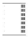
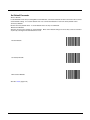
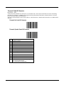
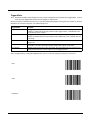
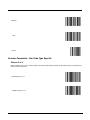
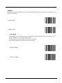
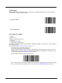
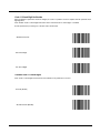
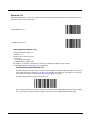
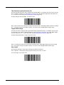
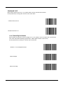
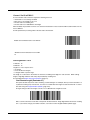
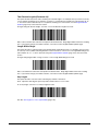
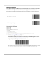
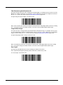
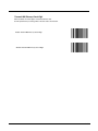
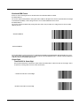
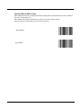
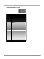
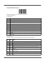
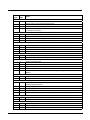
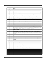
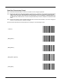
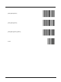
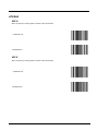
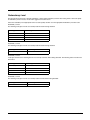
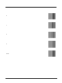
Security Level
The decoder offers four levels of decode security for delta bar codes, which include the Code 128 family, UPC/EAN, and Code
93.
Select increasing levels of security for decreasing levels of bar code quality.
There is an inverse relationship between security and decoder aggressiveness, so choose only that level of security necessary
for any given application.
Security Level 0
This setting allows the decoder to operate in its most aggressive state, while providing sufficient
security in decoding most ?in-spec? bar codes.
Security Level 1
Select this option if misdecodes occur. This default setting should eliminate most misdecodes.
Security Level 2
Select this option if Security level 1 fails to eliminate misdecodes.
Security Level 3
If Security Level 2 was selected and misdecodes still occur, select this security level. Be advised,
selecting this option is an extreme measure against misdecoding severely out of spec bar codes.
Selecting this level of security significantly impairs the decoding ability of the decoder. If this level of
security is necessary, try to improve the quality of the bar codes.
Select the security level appropriate for the bar code quality and then scan the appropriate Security Level bar code:
Security Level 0
* Security Level 1
Security Level 2
Security Level 3
5 - 79
Intercharacter Gap Size
The Code 39 and Codabar symbologies have an intercharacter gap that is typically quite small. Due to various bar codeprinting technologies, this gap can grow larger than the maximum size allowed, preventing the decoder from decoding the
symbol.
If this problem occurs, scan the Large Intercharacter Gaps parameter to tolerate these out-of-specification bar codes.
* Normal Intercharacter Gaps
Large Intercharacter Gaps
5 - 80
Imager Keypad Number Symbols
The bar code labels shown below represent a numeric keypad, with decimal values 0 through 9. Each label should be scanned
individually.
Use these numeric value symbols to enter numeric input in the course of performing an imager engine system configuration.
To correct an error or change a selection, scan Cancel then scan a desired bar code.
0
1
2
3
4
5
5 - 81
6
7
8
9
Cancel
5 - 82
6
Firmware Upgrade
Introduction
To update the ring scanner firmware, the ring scanner must be returned to Honeywell. Contact Customer Support (page 10-1)
for upgrade arrangements.
The procedure in this section is used to update the firmware in the Bluetooth module only.
Required:
• BlueCore Device Firmware Update program loaded on a computer. See Install BlueCore Device Update Wizard and Driver
(page 6-2) for instruction.
• Bluetooth Module Firmware update cable (8650A051CBLBTUPDATE).
• Firmware update file (Contact Customer Support (page 10-1) to obtain the latest Bluetooth Module firmware update file).
• A Bluetooth Ring Scanner Module and a fully charged battery.
Note: The firmware update cable is obsolete. If the cable is not available, the Bluetooth module must be returned to Honeywell
for firmware upgrades. Contact Customer Support (page 10-1) for upgrade arrangements.
Updating the Module Firmware
1. Remove the battery pack from the Bluetooth Ring Scanner module.
2. Disconnect the ring decoder cable.
3. Connect the USB end of the firmware update cable to the USB port on a computer.
4. Connect the I/O end of the firmware update cable to the I/O connector on the Bluetooth Ring Scanner module.
5. Insert a fully charged battery pack into the Bluetooth Ring Scanner module. The module powers up (multiple beeps and the
blue LED begins flashing).
6. Click Start > All Programs and start the BlueCore Device Firmware Update Wizard application.
7. Click Next to begin the upgrade process.
8. Select how the Bluetooth module is connected to your computer by choosing the Universal Serial Bus (USB) connection
type.
9. Click Next to continue.
10. Select Download a new version of the firmware, saving a copy of the current version first. Any previous version will be
replaced.
11. Browse to and highlight the latest firmware upgrade file. The file has a DFU extension. Click Select to continue.
6-1
12. The upgrade process proceeds and ends with a Successful Upgrade message (see below). The Bluetooth module may
emit a series of beeps or the blue LED may stop flashing and remain illuminated until the upgrade is finished.
13. Click Finish.
14. Remove the battery pack from the Bluetooth Module again.
15. Remove the firmware update cable from the I/O port.
16. At this point, the computer is ready to upgrade the next Bluetooth module, if desired.
Firmware Update Help
If the firmware update is interrupted due to loss of power or by removing the cable before the update is complete, the original
firmware will be destroyed and the Bluetooth Ring Scanner will not be able to run in normal operation mode. If this event occurs
the utility on the host computer indicates that the firmware upgrade was not successful.
This condition can be recovered by repeating the firmware update procedure.
Install BlueCore Device Update Wizard and Driver
Prerequisites:
• BlueCore Device Firmware Update program. Contact Customer Support (page 10-1) to obtain the BlueCore Device Firmware
Update file.
• A desktop/laptop Windows XP (or later) PC with an available USB port.
• A Bluetooth module and a fully charged battery.
• Bluetooth Module Firmware update cable (8650A051CBLBTUPDATE).
6-2
• Firmware update file (Contact Customer Support (page 10-1) to obtain the latest Bluetooth Module firmware update file).
Note: A Bluetooth module is required when performing the initial install of the BlueCore Device Firmware Update program on
the PC.
1. Install the BlueCore Device Update Wizard on a PC by doubleclicking the DFUWizardSetup[version].exe file located in the
Install folder.
2. Accept the license agreement, choose typical installation and then select Finish.
3. Insert the battery into the Bluetooth module to be updated (or used for the initial installation of the BlueCore Device Update
Wizard).
4. Insert the update cable into the Bluetooth module to be updated. The module should power up, indicated by a beep
sequence and the blue LED illuminating then flashing.
5. Insert the USB update cable into one of the host PC USB ports. The PC should recognize that a USB device has been
detected.
6. A message will appear stating the USB device driver needs to be installed on the PC.
7. The Windows Found New Hardware Wizard dialogue may appear requesting to connect to Windows Update to search for
software. Select No, not this time. Then click Next to continue. If the dialogue box shown below does not appear, continue.
8. The next dialogue box appears to help you install software for the Bluetooth Ring Scanner module.
9. Select Install from a list or specific location. Click Next to continue.
6-3
10. Browse to the driver location on the installation CD (/driver) or your hard drive, if the installation program was downloaded
to your hard drive, and click Next.
11. Click Continue Anyway when the dialog box appears stating “the driver has not passed Windows logo testing to verify
compatibility”.
12. Select Finish on the next dialog box.
13. Navigate to the Windows Device Manager screen. On Windows XP devices, one path to the Device Manager screen is
Start > Control Panel > System > Hardware tab and click the Device Manager button. Shown below is a sample of a
Device Manager screen.
14. Click the plus sign next to Universal Serial Bus controllers. Verify the BTRS Ringscanner in DFU mode is present. Close
all open windows and return to the PC desktop.
15. You are ready to update the Bluetooth Ring Scanner module firmware.
6-4
7
Decode Zones
Introduction
The scan ranges listed in the following tables are based on the following factors:
Decode zone is a function of various symbol characteristics including density, print contrast, wide-to-narrow ratio and edge
acuity. Symbols test labels are examples of optimum quality bar codes.
As distance decreases the visible scan line also decreases (visible scan length = 1.8 x distance to label x TAN (scan angle / 2).
The usable scan length is approximately 90% of visible scan line and must fully encompass the bar code label to be
successfully decoded. On larger symbol densities of 20 mil, 40 mil and 55 mil, this affects minimum decode distance.
+ / - 5° pitch is used to reduce the inhibiting effects of spectral reflection (glare) near 0° of the scan head aspect to the bar code.
Optimal operation is obtained at 2° to 15° pitch offset.
Scan rate of 25 + / - scans second with bi-directional redundancy.
The long range and advanced long range scanners support the aim-mode feature which allows generation of the laser for
aiming prior to actual bar code decoding with a duration from 1 sec to 8 sec.
The following “good scan and decode” ranges (decode zones) are related to a specific scan engine either integrated or
connected to your mobile device. If you do not see your type of scan engine listed, you may be using a tethered Bluetooth bar
code scanner or a serial port connected bar code scanner (these types of external scanners are not included in this list).
Ring Laser
Factory Default Scan Angle -- Wide (47°)
Typical Working Ranges
Guaranteed Working Ranges
Near
Far
Near
Far
4 mil
1.0 in / 2.50 cm
5.50 in / 13.97 cm
2.20 in / 5.60 cm
3.20 in / 8.13 cm
5 mil
1.25 in / 3.18 cm
8.00 in / 20.32 cm
2.20 in / 5.60 cm
5.50 in / 13.97 cm
Symbol Density
7.5 mil
1.50 in / 3.81 cm
13.00 in / 33.02 cm
2.00 in / 5.08 cm
9.50 in / 24.13 cm
10 mil
1.50 in / 3.81 cm
18.00 in / 45.72 cm
1.75 in / 4.45 cm
14.00 in / 35.56 cm
13 mil
1.50 in / 3.81 cm
24.00 in / 60.96 cm
1.75 in / 4.45 cm
18.00 in / 45.72 cm
15 mil
1.50 in / 3.81 cm
28.00 in / 71.12 cm
1.75 in 4.45 cm
21.00 in / 53.34 cm
20 mil
1.75 in / 4.45 cm
33.00 in / 83.82 cm
*
27.00 in / 68.58 cm
40 mil
*
36.00 / 91.44 cm
*
28.00 in / 71.12 cm
55 mil
*
45.00 in / 114.30 cm
*
34.00 in / 86.36 cm
* Near ranges are largely dependent upon the width of the bar code and the scan angle.
7-1
Ring Imager
The decode distances in this section are based on the current Focus Mode setting in the ring imager. Note that when Far Focus
is set, the imager is optimized to read at its far position. With Near Focus, the imager is optimized to read at its near position.
Smart Focus toggles the focus position after every frame.
The decode distances in this section are based on the Focus Mode set currently in the ring imager.
PL4407 Near Focus Decode Distances
Typical Working Ranges
Guaranteed Working Ranges
Near
Near
Symbol Density
Far
Far
5.0 mil
3.5 in / 8.9 cm
7.0 in / 17.8 cm
4.25 in / 10.8 cm
6.0 in / 15.2 cm
6.67 mil
3.75 in / 9.5 cm
6.0 in / 15.2 cm
4.5 in / 11.4 cm
5.75 in / 14.6 cm
7.5 mil
2.75 in / 7.0 cm
7.75 in / 19.7 cm
3.5 in / 8.9 cm
6.5 in / 16.5 cm
10 mil
3.25 in / 8.3 cm
7.25 in / 18.4 cm
4.0 in / 10.2 cm
6.5 in / 16.5 cm
13 mil
2.25 in / 5.7 cm
8.75 in / 22.2 cm
3.0 in / 7.6 cm
7.0 in / 17.8 cm
15 mil
*
7.5 in / 19.1 cm
*
7.0 in / 17.8 cm
20 mil
*
11.0 in / 27.9 cm
*
9.5 in / 24.1 cm
* Near ranges are field-of-view limited. Working range specifications at temperature 23° C.
PL4407 Far Focus Decode Distances
Typical Working Ranges
Guaranteed Working Ranges
Near
Far
Near
Far
5.0 mil
6.5 in / 16.5 cm
7.5 in / 19.1 cm
N/A
N/A
6.67 mil
N/A
N/A
N/A
N/A
7.5 mil
4.25 in / 10.8 cm
10.0 in / 25.4 cm
5.5 in / 14.0 cm
8.5 in / 21.6 cm
10 mil
5.75 in / 14.6 cm
10.25 in / 26.0 cm
6.5 in / 16.5 cm
9.5 in / 24.1 cm
13 mil
3.0 in / 7.6 cm
16.0 in / 40.6 cm
3.75 in / 9.5 cm
13 in / 33.0 cm
15 mil
*
13.75 in / 34.9 cm
*
12.75 in / 32.4 cm
20 mil
*
21.5 in / 51.6 cm
*
17.0 in / 43.2 cm
Symbol Density
* Near ranges are field-of-view limited. Working range specifications at temperature 23° C.
7-2
PL4407 Toggled Focus Decode Distances
Typical Working Ranges
Guaranteed Working Ranges
Near
Far
Near
Far
5.0 mil
3.5 in / 8.9 cm
7.5 in / 19.1 cm
4.25 in / 10.8 cm
6.0 in / 15.24 cm
6.67 mil
3.75 in / 9.5 cm
6.0 in / 15.24 cm
4.5 in / 11.4 cm
5.75 in / 14.61 cm
7.5 mil
2.75 in / 7.0 cm
10.0 in / 25.4 cm
3.5 in / 8.9 cm
8.5 in / 21.6 cm
10 mil
3.25 in / 8.3 cm
10.25 in / 26.0 cm
4.0 in / 10.2 cm
9.5 in / 24.1 cm
13 mil
2.25 in / 5.7 cm
16.0 in / 40.6 cm
3.0 in / 7.6 cm
13 in / 33.0 cm
15 mil
*
13.75 in / 34.9 cm
*
12.75 in / 32.4 cm
20 mil
*
21.5 in / 51.6 cm
*
17.0 in / 43.2 cm
Symbol Density
* Near ranges are field-of-view limited. Working range specifications at temperature 23° C.
PL4407 Decode Distances in Darkness
Typical Working Ranges
Symbol Density
Focus Position
Near
Far
5.0 mil
Near
Far
3.5 in / 8.9 cm
6.5 in / 16.5 cm
5.875 in / 14.1 cm
N/A
6.67 mil
Near
Far
3.75 in / 9.5 cm
N/A
5.75 in / 14.6 cm
N/A
7.5 mil
Near
Far
2.75 in / 7.0 cm
4.25 in / 10.8 cm
6.875 in / 17.5 cm
7.125 in / 18.1 cm
10 mil
Near
Far
3.25 in / 8.3 cm
5.75 in / 14.6 cm
6.375 in / 16.2 cm
7.25 in / 18.4 cm
13 mil
Near
Far
2.25 in / 5.7 cm
3.00 in / 7.6 cm
7.375 in / 18.7 cm
8.375 in / 21.3 cm
* Near ranges are field-of-view limited. Working range specifications at temperature 23° C.
7-3
7-4
8
Battery Chargers
Unpacking your Battery Charger
After you open the shipping carton containing the product, take the following steps:
• Check for damage during shipment. Report damage immediately to the carrier who delivered the carton.
• Make sure the items in the carton match your order.
• Save the shipping container for later storage or shipping.
Introduction
The Bluetooth Ring Scanner (BTRS) Module Battery Chargers are designed to simultaneously charge eight rechargeable
Lithium Ion (Li-Ion) batteries. The time required for charging is dependent upon the battery internal temperature and condition.
The Bluetooth Ring Scanner Module Single-bay charger is designed to charge one rechargeable Lithium Ion (Li-Ion) battery
pack at a time.
The battery charger should be located in an area where it:
Is well ventilated.
• Is not in high traffic areas.
• Locates or orients the AC cord so that it will not be stepped on, tripped over or subjected to damage or stress.
• Has enough clearance to allow easy access to the power port on the back of the device.
• Is protected from rain, dust, direct sunlight or inclement weather.
This device is intended for indoor use only and requires an indoor AC power source. The charger is not approved for use in
Hazardous Locations.
This device cannot charge/recharge coin cell batteries sealed inside a mobile device, if any.
This information is intended to familiarize the user with the safety and operating instructions necessary to use the Bluetooth
Ring Scanner Battery Charger (Model 8650377CHARGER, 8650378CHARGER, 8650379CHARGER, 8650380CHARGER) to
charge rechargeable lithium-ion batteries (8650376BATTERY) .
This guide should be readily available to all users and maintenance personnel using this battery charger.
Store the charger and batteries when not in use in a cool, dry, protected place.
8-1
Cautions and Warnings
Warning: The Bluetooth Ring Scanner Battery Charger is to be used to charge an I.T.E. Recognized Battery pack manufactured
by Helix Co., Ltd. (Model: HNP-40, LXE, P/N 161987-0001, rating 3.7V, 750mAh). Charging any other type of battery pack in
the Bluetooth Ring Scanner battery charger is prohibited.
Warning: Use the provided AC power supply, only, with the Bluetooth Ring Scanner Battery Charger. Using any other type of
AC power supply is prohibited.
Battery Charger
• There is a risk of explosion if the Bluetooth Ring Scanner Li-Ion battery in the charging pocket is replaced by an incorrect
type. Other batteries or battery packs may burst causing injury or property damage.
• Do not insert any other type of Li-Ion battery in the Bluetooth Ring Scanner battery charging pocket.
• Do not allow cleaning agents of any kind to contact the battery charging contacts; they may be damaged. If necessary,
clean them with a soft-bristle, dry brush or compressed air.
• Disconnect the charger from AC power by pulling the plug; not the cord.
• Use care when inserting battery. Do not “slam” or slide the battery into the pocket, this could damage the charger.
• Keep dirt and foreign objects out of the battery pocket. Do not short circuit any of the contacts in the battery pocket, this
could result in injury or property damage.
• Do not disassemble or perform modifications to the charger. There are no user serviceable components in the charger.
Lithium-Ion Battery Pack
•
•
•
•
•
•
•
•
•
•
•
•
8-2
Dispose of used Li-Ion batteries according to the instructions for the type of battery.
When not in use, lay the battery pack contact-side up in a protected environment.
Do not store the Li-Ion battery pack in direct sunlight or anywhere the battery pack cannot cool down.
If the Li-Ion battery pack is hot after removal from the Bluetooth Ring Scanner, allow it to cool at room temperature or in
a cool air stream before placing it in the charger.
Do not dispose of Li-Ion batteries into a fire. Burning will generate hazardous vapors and may cause the battery to
explode. Failure to observe this warning may result in injury from inhalation of vapors or burns from flying debris.
Do not immerse Li-Ion batteries in water or any other liquid. If batteries are immersed, contact Honeywell.
Do not disassemble or perform modifications to the battery. There are no user serviceable components in the battery.
Do not place the Li-Ion battery into a pocket or toolbox with conductive objects (coins, keys, tools, etc.). A Li-Ion battery
placed on damp ground or grass could be electrically shorted.
Do not store Li-Ion batteries above 140°F (60°C) for extended periods.
Failure to observe these warnings could result in injury or damage to the battery from rapid discharge of energy or battery
overheating.
Electrolyte Burns. Be careful when handling batteries. If a battery is broken or shows signs of leakage do not attempt to
charge it. Dispose of it! Lead and Nickel-based cells contain a chemical solution that burns skin, eyes, etc. Leakage from
cells is the only possible way for such exposure to occur. In this event, rinse the affected area thoroughly with water. If
the solution contacts the eyes, get immediate medical attention.
Electrical Burns. Batteries are capable of delivering high currents when accidentally shorted. Accidental shorting can
occur when contact is made with jewelry, metal surfaces, conductive tools, etc., making the objects very hot. Never place
a charged battery in a pocket or case with keys, coins, or other metal objects.
Charging Batteries
New batteries should be charged fully before first use. The life and capacity of a Lithium Ion battery pack can vary significantly
depending on the discharge current and the environment in which it is used.
When a battery is placed in a charging pocket, the battery charger begins charging the battery. There is a slight delay while the
charger evaluates the condition of the battery (ambient temperature, remaining charge, etc.) before charging begins.
As with all batteries, expect to see a reduction in the total number of operations a fully charged battery pack can deliver as it
ages. When the battery reaches end of life (end-of-life occurs after 500 charge/discharge cycles) it must be replaced.
Battery packs do not need to be fully discharged between charge cycles.
While charging, the charger and battery pack will generate enough heat to feel warm. This is normal and does not indicate a
problem.
Eight Bay Battery Charger
Front View
1. Power Cable Connection location
2. Battery Charging
Pocket
3. LED Indicator
4. LED Function
Legend
Place the charger on a horizontal, hard surface or fasten securely to a wall using the mounting holes. Mounting hardware
is not supplied by Honeywell.
Plug the 2 prong end of the power cord into a properly grounded AC outlet. The power cord is included for US models.
Power cord is sold separately for other models.
Locate or orient the AC cord so that it will not be stepped on, tripped over or subjected to damage or stress.
8-3
Charging Pocket
Battery charger
1. Battery Pocket
2. Battery Charging Contacts
There are very small battery retaining mechanisms in the battery pockets.
Footprint and Mounting Hole Location
Installation
Assemble the Power Supply
Assemble the AC adapter for the Bluetooth Ring Scanner Module (BTRS) battery charger before connecting it to the
battery charger.
The AC power supply for the battery charger is shipped with the battery charger. For non-US models a power cord is
required.
1. Plug the 2-prong cable into an AC wall outlet.
2. Firmly press the female end of the power cable into the male connector on the AC power adapter.
3. AC power is now being applied to the power adapter.
Setup
Prerequisite: The AC Adapter is assembled and receiving AC power.
Do not insert battery packs until the battery charger has finished powering up:
8-4
1. Insert the power connector into the power outlet at the back of the battery charger.
2. AC power is now being applied to the battery charger and it begins to power up.
3. Charge pocket LEDs flash while the battery charger enters and exits the startup check.
4. When the charge pocket LEDs are not illuminated, the battery charger is ready for use.
Inserting a Battery into the Charging Pocket
Caution! It is important that battery packs are inserted into the charging pocket correctly. Inserting the battery incorrectly
could result in damage to the battery pack or the charger.
Caution! Do not “slam” the battery pack into the charging pocket. Damage may result.
When preparing the battery pack for insertion into the battery charging pocket, hold the battery with its three charging contacts in line with the three charging contacts in the charging pocket (use the direction of the arrow on the battery label as a
guide).
If necessary, stabilize the charger with your hand before inserting a battery. Firmly press the battery straight down into the
battery charging pocket.
Removing the Battery from the Charging Pocket
If necessary, stabilize the charger with one hand before removing a battery from a charging pocket. Grasp the battery
firmly and pull it straight up and out of the charging pocket.
Interpreting the Charging Pocket LEDs
The status of the charge operation is indicated by the color of the LED for each charging pocket.
RED Continuous - on any charge pocket
Continuous red means the battery pack is charging.
RED FLASHING - on all charge pockets
Battery charger fault or failure.
GREEN - on any charge pocket
Continuous green means the battery pack charge is complete - Battery is Ready.
• Continuous - Charger is plugged in – Battery is not receiving power through the charging pocket, or battery is not fully
seated in charging pocket.
• YELLOW - on any charge pocket
• Continuous yellow / amber means the battery pack temperature is out of range. The charging pocket is in standby mode
while the pocket waits for the battery pack to warm up or cool down.
• The battery pack has been inserted incorrectly. Take the battery out, turn it around, align the charging terminals on the
battery and in the pocket and insert the battery again.
• NO LIGHT - on any charge pocket
• No light on a charge pocket means there is no battery pack installed
• or the battery pack in the pocket is not fully inserted
• or a defective or damaged battery pack is installed
• or the charger is defective or damaged. Refer to Battery Charger Help (page 8-8).
• NO LIGHT - on all charge pockets
• No light means there is no AC power available to the battery charger or there is power but there are no batteries in any
charging bay.
8-5
Charge Timer
The battery pocket timers are dynamic and based upon the capacity of the battery pack. There is a timeout period for the
soft start and another timeout period for the overall time required to charge the battery to full capacity. The pocket’s LED
flashes red when the charging pocket timeout period has expired.
Single Bay Charger
1. Battery Charging Pocket
2. Power LED Indicator
3. Power Connector location
4. Single-bay Charger Power plug (US models only), adapter cable optional.
The single-bay charger power plug mounts the single-bay charger to an AC outlet.
Connect the power plug or adapter cable to the single-bay charger.
Insert the power plug into a properly grounded outlet.
Charging Pocket
1. Battery Pocket
2. Battery Charging Contacts
3. Single Bay Charging Battery Retaining Springs
There are very small battery retaining mechanisms in the single charger battery pocket.
Inserting a Battery into the Charging Pocket
Caution! It is important that battery packs are inserted into the charging pocket correctly. Inserting the battery incorrectly
could result in damage to the battery pack or the charger.
Caution! Do not “slam” the battery pack into the charging pocket. Damage may result.
When preparing the battery pack for insertion into the battery charging pocket, hold the battery with its three charging contacts in line with the three charging contacts in the charging pocket (use the direction of the arrow on the battery label as a
guide).
If necessary, stabilize the charger with your hand before inserting a battery. Firmly press the battery straight down into the
battery charging pocket.
8-6
Removing the Battery from the Charging Pocket
If necessary, stabilize the charger with one hand before removing a battery from a charging pocket. Grasp the battery
firmly and pull it straight up and out of the charging pocket.
Interpreting the Charging LED
The status of the charge operation is indicated by the color of the LED.
RED - The battery pack is charging.
GREEN - The battery pack is charged.
Charge Timer
The Single-bay charger does not contain a timer. The charger provides a soft charge mode for deeply discharged batteries,
a fast charge mode and a constant-charge mode that maintains power levels in charged batteries. Battery charge time to
full capacity is three hours.
8-7
Battery Charger Help
The following is intended as an aid in determining whether the battery pack or the charger may be malfunctioning:
Issue
Cause
Solution
Battery pack does not fit in charging
pocket.
Different manufacturer's battery pack,
or there is an object in the charging
pocket.
Check if the Bluetooth Ring Scanner
battery pack has Honeywell part number
8650376BATTERY/161987-0001 on the
label. If not, do not use.
Remove the object from the charging
pocket.
No battery pack in charger, but any
of the LEDs are on.
Dirt or foreign objects are in the
charging pocket.
Unplug charger from AC supply. Remove
any dirt or foreign objects from the
charging pocket. If the LEDs continue to
remain ON, the charger may be defective.
Return charger to an authorized
Honeywell service center.
Charger is plugged into a live outlet,
battery pack is inserted, but RED
LED is OFF and no other LEDs are
on, or all LEDs are off.
Battery pack is not making contact with
battery charge terminals in the
charging pocket.
Push battery pack in firmly. Do not “slam”
the battery pack into the charging pocket.
Charger is plugged into a live outlet,
battery pack is inserted, but RED
LED is OFF and no other LEDs are
on, or all LEDs are off.
Faulty battery pack.
Replace battery pack.
Charger is plugged into a live outlet,
battery pack is inserted, but RED
LED is OFF and no other LEDs are
on, or all LEDs are off.
New battery pack, same result.
Contact Customer Support (page 10-1)
for replacement options.
When you first put a fully charged
battery pack in the charging pocket,
the RED LED comes on, indicating
the battery pack is charging.
During the first few minutes, the battery
charger checks the battery pack for
correct voltage and charge state.
During this time the LED is RED and is
continuously ON. After charging is
complete, the LED is GREEN.
There is nothing wrong with the battery
pack or charger.
Do not “top off” a fully charged battery
pack by repeatedly placing it in the
charging pocket. The battery pack may
overheat and be damaged.
LED is flashing RED at any pocket.
Current could not be sourced through
the battery pack due to age,
exhaustion or damage to the cell(s).
The battery pack does not
communicate with the charger.
Contact Customer Support (page 10-1)
for battery pack replacement options.
LED is flashing RED at any pocket.
The charger’s timeout period has
expired.
Make sure that the battery pack
temperature is within specification and
retry charging. Contact Customer
Support (page 10-1) if problem repeats,
for battery pack replacement options.
LED is flashing RED at any pocket.
The battery pack voltage has not
reached 4.2V within the timeout period
and the charger has timed out.
Contact Customer Support (page 10-1)
for battery pack replacement options.
8-8
Issue
Cause
Solution
Solid YELLOW / AMBER LED when
battery pack is inserted in the
charging pocket.
The battery pack is too hot or too cold
to charge.
Remove battery pack from the charging
pocket and allow it to adjust to room
temperature.
If the battery pack is left in the charging
pocket, it will cool down or warm to a
temperature upon which the charger will
begin the charge cycle. However,
depending on the temperature of the
battery, it may take 2-3 hours to adjust.
The cool-down / warm-up of a battery
pack is much quicker if the battery is not
in the charging pocket.
Battery pack is inserted backwards.
Remove the battery pack, line up the
charging terminals on the battery pack
with the charging terminals in the
charging pocket and insert the battery
again.
Charger Cleaning, Storage and Service
Cleaning
Unplug the charger from the power source before cleaning or removing debris from charging pockets.
Use only mild detergent with a slightly damp cloth to clean the outside of the charger. Do not use solvents or flammable
cleaners. Allow the case to dry fully before using again.
Do not allow cleaning agents of any kind to contact the charging contacts; they may be damaged. If necessary, clean them
with a soft-bristle, dry brush or compressed air.
Storage
Remove all batteries from the charging bays and disconnect AC power before placing the charger in storage. It should be
stored in a cool, dry place, protected from weather and airborne debris.
Battery packs should be kept in a cool, dry place whenever possible. Do not store battery packs in direct sunlight, on a
metal surface, or anywhere the battery pack cannot cool down. Do not leave the battery pack in a non-operating charger.
The battery pack may discharge through the charger rather than hold its charge.
Service
There are no user serviceable parts in the Rechargeable Lithium Ion Battery or the Charger. Contact Customer Support
(page 10-1) should your charger require service.
Battery Cleaning, Storage and Service
Cleaning
The battery pack should not require cleaning unless it has become heavily soiled. Old or damaged batteries should be disposed of promptly and properly. The best way to dispose of used batteries is to recycle them. Battery recycling facilities
recover the Nickel, Lithium or Lead from old batteries to manufacture new batteries.
Use only mild detergent with a slightly damp cloth to clean the outside of the battery. Do not use solvents or flammable
cleaners. Allow the case to dry fully before using again.
Do not allow cleaning agents of any kind to contact the charging contacts; they may be damaged. If necessary, clean them
with a soft-bristle, dry brush or compressed air.
Storage
Battery packs should be stored, charging contact side up, in a cool dry place, protected from weather and airborne debris,
whenever possible.
Do not store battery packs in direct sunlight, on a metal surface, or anywhere the battery pack cannot cool down.
8-9
Do not leave the battery pack in a non-operating charger. The battery pack may discharge through the charger rather than
hold its charge.
Battery packs may leak up to 1 mA current through the battery contacts when left in an unpowered charger pocket.
Service
There are no user serviceable parts in the Lithium Ion Battery Pack. Contact Customer Support (page 10-1) for battery disposal and replacement options.
8 - 10
9
Technical Specifications
Bluetooth Ring Scanner Module
Technical Specifications
I/O Port
A 22 spring-pin, symmetrical port
Module Size
Without Scanner : Height 0.75” / 1.90cm x Width 1.75” / 4.44cm x Length 2.4” / 6.1cm
With Scanner : Height 0.75” / 1.90cm x Width 1.75” / 4.44cm x Length 2.9” / 7.4cm
Module Weight
2.15oz / 60.9g with battery / 1.60oz / 45g without battery
4.05 – 4.15oz / 114g – 117g with battery and scanner
Ring Scanner : 1.75oz / 49.6g
Ring Imager : 1.85oz / 52.4g
Battery
Li-Ion, 3.7v 750mAh with a 500 charge/discharge life cycle
Environmental Specifications
Operating Temperature
-4° F to 122° F (-20° C to +50° C)
Storage Temperature
-40° F to 158° F (-40°C to +60°C)
Water and Dust
Resistance
Sealed to IP-54 specifications or better
Humidity
5% to 95% relative humidity, non-condensing
Corrosion
Corrosion resistant when exposed to water and common cleaning chemicals
Chemical Resistance
Corrosion resistant when exposed to water and common cleaning chemicals
Abrasion Resistance
Housing resists normal abrasion from dirty hands.
Bluetooth Radio
The CF Bluetooth Radio in the Bluetooth Ring Scanner is Bluetooth Special Interest Group (SIG) Qualified, is listed as an
EPL (End Product Listing) and with QDID: B011904.
Bluetooth Ring Scanner Battery Charger
Battery: Li-ion 3.7v 750mAh battery with a 500 charge/discharge life cycle
Electrical
Battery packs may leak up to 1mA current through the battery contacts when left in an unpowered battery charger charging
pocket.
Parameter
Minimum
Maximum
Note
Power Supply Input Voltage (V AC-IN)
100 VAC
240VAC
Auto-switching
Power Supply Input Frequency (freq)
47Hz
63Hz
9-1
Temperature
Function
Minimum
Maximum
Note
Operating
0°C (32°F)
Battery charger: +45°C (113°F)
Single-charger: +40°C (100°F)
Battery Pack
Charging
0°C (32°F)
+45°C (113°F)
Battery packs will not begin charging when
their internal temperature is outside this range.
Storage
-10°C (14°F)
+50°C (120°F)
Unit is off.
Dimensions
Parameter
Multi-bay Charger
Single-bay Charger
Weight
Battery: 0.55oz / 15.6g
Without batteries: 9.10oz / 258g
With 8 batteries: 13.85oz / 392g
AC Adapter: 6.40oz / 181g
Without battery: 2.05oz / 58g
With battery: 2.75oz / 78g
With battery and power plug: 3.25oz / 92g Power plug: 0.70oz
/ 19.8g
Plug Type
IEC; 2-prong
IEC; 2-prong
Length
9” / 23cm
2.9” / 7.4cm (with 2-prong plug 4” / 10cm)
Width
3.25” / 8.25cm
1.9” / 4.8cm
Height
1.25” / 3.17cm (with batteries 2.5” /
6.3cm)
1.15” / 2.92cm (with battery 2.25” / 5.71cm)
Mounting
Distance between mounting holes: 5.9”
/ 14.9cm
Mounts to AC outlet w/2 prong plug
ASCII Character Equivalents
Values from 1128 through 1255 (hex values 80h through FFh) may also be set. But the conversion of those characters to
printable characters is not standardized. Therefore, they are not included in the table.
9-2
Scan Value
Hex Value
Full ASCII Code 39
Encode Char.
1000
00h
%U
CTRL 2
1001
0lh
$A
CTRL A
Keystroke
1002
02h
$B
CTRL B
1003
03h
$C
CTRL C
1004
04h
$D
CTRL D
1005
05h
$E
CTRL E
1006
06h
$F
CTRL F
1007
07h
$G
CTRL G
1008
08h
$H
CTRL H
1009
09h
$I
CTRL I
1010
0Ah
$J
CTRL J
1011
0Bh
$K
CTRL K
1012
0Ch
$L
CTRL L
1013
0Dh
$M
CTRL M
1014
0Eh
$N
CTRL N
1015
0Fh
$O
CTRL O
Full ASCII Code 39
Encode Char.
Scan Value
Hex Value
Keystroke
1016
10h
$P
CTRL P
1017
1lh
$Q
CTRL Q
1018
12h
$R
CTRL R
1019
13h
$S
CTRL S
1020
14h
$T
CTRL T
1021
15h
$U
CTRL U
1022
16h
$V
CTRL V
1023
17h
$W
CTRL W
1024
18h
$X
CTRL X
1025
19h
$Y
CTRL Y
1026
lAh
$Z
CTRL Z
1027
lBh
%A
CTRL [
1028
lCh
%B
CTRL \
1029
lDh
%C
CTRL ]
1030
lEh
%D
CTRL 6
1031
lFh
%E
CTRL -
1032
20h
Space
Space
1033
21h
/A
!
1034
22h
/B
‘
1035
23h
/C
#
1036
24h
/D
$
1037
25h
/E
%
1038
26h
/F
&
1039
27h
/G
’
1040
28h
/H
(
1041
29h
/I
)
1042
2Ah
/J
*
1043
2Bh
/K
+
1044
2Ch
/L
,
1045
2Dh
-
-
1046
2Eh
.
.
1047
2Fh
/
/
1048
30h
0
0
1049
31h
1
1
1050
32h
2
2
1051
33h
3
3
1052
34h
4
4
1053
35h
5
5
1054
36h
6
6
1055
37h
7
7
1056
38h
8
8
1057
39h
9
9
1058
3Ah
/Z
:
9-3
Scan Value
9-4
Hex Value
Full ASCII Code 39
Encode Char.
Keystroke
1059
3Bh
%F
;
1060
3Ch
%G
<
1061
3Dh
%H
=
1062
3Eh
%I
>
1063
3Fh
%J
?
1064
40h
%V
@
1065
41h
A
A
1066
42h
B
B
1067
43h
C
C
1068
44h
D
D
1069
45h
E
E
1070
46h
F
F
1071
47h
G
G
1072
48h
H
H
1073
49h
I
I
1074
4Ah
J
J
1075
4Bh
K
K
1076
4Ch
L
L
1077
4Dh
M
M
1078
4Eh
N
N
1079
4Fh
O
O
1080
50h
P
P
1081
51h
Q
Q
1082
52h
R
R
1083
53h
S
S
1084
54h
T
T
1085
55h
U
U
1086
56h
V
V
1087
57h
W
W
1088
58h
X
X
1089
59h
Y
Y
1090
5Ah
Z
Z
1091
5Bh
%K
[
1092
5Ch
%L
\
1093
5Dh
%M
]
1094
5Eh
%N
^
1095
5Fh
%O
-
1096
60h
%W
‘
1097
61h
+A
a
1098
62h
+B
b
1099
63h
+C
c
1100
64h
+D
d
1101
65h
+E
e
Scan Value
Hex Value
Full ASCII Code 39
Encode Char.
Keystroke
1102
66h
+F
f
1103
67h
+G
g
1104
68h
+H
h
1105
69h
+I
i
1106
6Ah
+J
j
1107
6Bh
+K
k
1108
6Ch
+L
1
1109
6Dh
+M
m
1110
6Eh
+N
n
1111
6Fh
+O
o
1112
70h
+P
p
1113
71h
+Q
q
1114
72h
+R
r
1115
73h
+S
s
1116
74h
+T
t
1117
75h
+U
u
1118
76h
+V
v
1119
77h
+W
w
1120
78h
+X
x
1121
79h
+Y
y
1122
7Ah
+Z
z
1123
7Bh
%P
{
1124
7Ch
%Q
|
1125
7Dh
%R
}
1126
7Eh
%S
1127
7Fh
~
Undefined
9-5
9-6
10
Customer Support
Technical Assistance
If you need assistance installing or troubleshooting your device, please contact us by using one of the methods below:
Knowledge Base: www.hsmknowledgebase.com
Our Knowledge Base provides thousands of immediate solutions. If the Knowledge Base cannot help, our Technical Support
Portal (see below) provides an easy way to report your problem or ask your question.
Technical Support Portal: www.hsmsupportportal.com
The Technical Support Portal not only allows you to report your problem, but it also provides immediate solutions to your
technical issues by searching our Knowledge Base. With the Portal, you can submit and track your questions online and send
and receive attachments.
Web form: www.hsmcontactsupport.com
You can contact our technical support team directly by filling out our online support form. Enter your contact details and the
description of the question/problem.
Telephone: www.honeywellaidc.com/locations
For our latest contact information, please check our website at the link above.
Product Service and Repair
Honeywell International Inc. provides service for all of its products through service centers throughout the world. To obtain
warranty or non-warranty service, please visit www.honeywellaidc.com and select Support > Contact Service and Repair to
see your region’s instructions on how to obtain a Return Material Authorization number (RMA #). You should do this prior to
returning the product.
Limited Warranty
Honeywell International Inc. (“HII”) warrants its products to be free from defects in materials and workmanship and to conform to
HII’s published specifications applicable to the products purchased at the time of shipment. This warranty does not cover any
HII product which is (i) improperly installed or used; (ii) damaged by accident or negligence, including failure to follow the proper
maintenance, service, and cleaning schedule; or (iii) damaged as a result of (A) modification or alteration by the purchaser or
other party, (B) excessive voltage or current supplied to or drawn from the interface connections, (C) static electricity or electrostatic discharge, (D) operation under conditions beyond the specified operating parameters, or (E) repair or service of the
product by anyone other than HII or its authorized representatives.
This warranty shall extend from the time of shipment for the duration published by HII for the product at the time of purchase
(“Warranty Period”). Any defective product must be returned (at purchaser’s expense) during the Warranty Period to HII factory
or authorized service center for inspection. No product will be accepted by HII without a Return Materials Authorization, which
may be obtained by contacting HII. In the event that the product is returned to HII or its authorized service center within the
Warranty Period and HII determines to its satisfaction that the product is defective due to defects in materials or workmanship,
HII, at its sole option, will either repair or replace the product without charge, except for return shipping to HII.
EXCEPT AS MAY BE OTHERWISE PROVIDED BY APPLICABLE LAW, THE FOREGOING WARRANTY IS IN LIEU OF ALL
OTHER COVENANTS OR WARRANTIES, EITHER EXPRESSED OR IMPLIED, ORAL OR WRITTEN, INCLUDING, WITHOUT
LIMITATION, ANY IMPLIED WARRANTIES OF MERCHANTABILITY OR FITNESS FOR A PARTICULAR PURPOSE, OR
NON-INFRINGEMENT.
HII’S RESPONSIBILITY AND PURCHASER’S EXCLUSIVE REMEDY UNDER THIS WARRANTY IS LIMITED TO THE
REPAIR OR REPLACEMENT OF THE DEFECTIVE PRODUCT WITH NEW OR REFURBISHED PARTS. IN NO EVENT
SHALL HII BE LIABLE FOR INDIRECT, INCIDENTAL, OR CONSEQUENTIAL DAMAGES, AND, IN NO EVENT, SHALL ANY
LIABILITY OF HII ARISING IN CONNECTION WITH ANY PRODUCT SOLD HEREUNDER (WHETHER SUCH LIABILITY
ARISES FROM A CLAIM BASED ON CONTRACT, WARRANTY, TORT, OR OTHERWISE) EXCEED THE ACTUAL AMOUNT
PAID TO HII FOR THE PRODUCT. THESE LIMITATIONS ON LIABILITY SHALL REMAIN IN FULL FORCE AND EFFECT
EVEN WHEN HII MAY HAVE BEEN ADVISED OF THE POSSIBILITY OF SUCH INJURIES, LOSSES, OR DAMAGES. SOME
STATES, PROVINCES, OR COUNTRIES DO NOT ALLOW THE EXCLUSION OR LIMITATIONS OF INCIDENTAL OR
CONSEQUENTIAL DAMAGES, SO THE ABOVE LIMITATION OR EXCLUSION MAY NOT APPLY TO YOU.
10 - 1
All provisions of this Limited Warranty are separate and severable, which means that if any provision is held invalid and
unenforceable, such determination shall not affect the validity of enforceability of the other provisions hereof. Use of any
peripherals not provided by the manufacturer may result in damage not covered by this warranty. This includes but is not limited
to: cables, power supplies, cradles, and docking stations. HII extends these warranties only to the first end-users of the
products. These warranties are non-transferable.
The duration of the limited warranty for the Bluetooth Ring Scanner Module is 1 year.
The duration of the limited warranty for the Bluetooth Ring Scanner Module Battery Charger is 1 year.
The duration of the limited warranty for the Bluetooth Ring Scanner Module 750mAh Li-Ion Battery is 6 months.
The duration of the limited warranty for the Bluetooth Ring Scanner Module Ring Scanner and Ring Imager is 1 year.
The duration of the limited warranty for the Bluetooth Ring Scanner fabric accessories (e.g., case, straps) is 90 days.
10 - 2
Honeywell Scanning & Mobility
9680 Old Bailes Road
Fort Mill, SC 29707
www.honeywellaidc.com
™
8650-UG Rev A
1/15