1
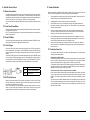
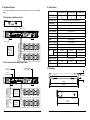
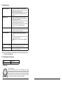
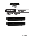
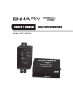
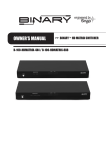
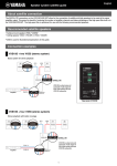
Installation Manual
ECA-70AMP-2D-150A
©2014 Episode™
2- Channel 70 Volt Power Amplifiers
ECA-70AMP-2D-300A
ECA-70AMP-2D-500A
Pg. 1
1. Important Safety Instructions
1. Consignes de Sécurité Importantes
Warning: To reduce the risk of fire or electric shock, do not expose this apparatus to rain or moisture.
1.
2.
3.
4.
5.
6.
7.
8.
9.
10.
11.
12.
13.
14.
15.
16.
17.
18.
Read these instructions.
Keep these instructions.
Heed all warnings.
Follow all instructions.
Do not use this apparatus near water.
Clean only with dry cloth.
Do not block any ventilation openings. Install in accordance with the manufacturer’s instructions.
Do not install near any heat sources such as radiators, heat registers, stoves, or other apparatus (including
amplifiers) that produce heat.
Do not defeat the safety purpose of the polarized or grounding-type plug. A polarized plug has two blades
with one wider than the other. A grounding type plug has two blades and a third grounding prong. The
wide blade or the third prong are provided for your safety. If the provided plug does not fit into your outlet,
consult an electrician for replacement of the obsolete outlet.
Protect the power cord from being walked on or pinched particularly at plugs, convenience receptacles, and
the point where they exit from the apparatus.
Only use attachments/accessories specified by the manufacturer.
Use only with the cart, stand, tripod, bracket, or table specified
by the manufacturer, or sold with the apparatus. When a cart is
used, use caution when moving the cart/apparatus combination
to avoid injury from tip-over. (See Figure on Right)
Unplug this apparatus during lightning storms or when unused
for long periods of time.Refer all servicing to qualified service
personnel. Servicing is required when the apparatus has been
damaged in any way, such as power-supply cord or plug is
damaged, liquid has been spilled or objects have fallen into the
apparatus, the apparatus has been exposed to rain or moisture,
does not operate normally, or has been dropped.
This product employs a Class I (or grounded) construction and shall be connected to a mains socket outlet
with a protective earthed (or ground) connection.
DO NOT EXPOSE THIS EQUIPMENT TO DRIPPING OR SPLASHING AND ENSURE THAT NO OBJECTS
FILLED WITH LIQUIDS, SUCH AS VASES, ARE PLACED ON THE EQUIPMENT.
TO COMPLETELY DISCONNECT THIS EQUIPMENT FROM THE AC MAINS, DISCONNECT THE POWER
SUPPLY CORD PLUG FROM THE AC RECEPTACLE.
THE MAIN PLUG OF THE POWER SUPPLY CORD SHALL REMAIN READILY OPERABLE.
CAUTION: TO REDUCE THE RISK OF ELECTRICAL SHOCK, DO NOT REMOVE COVER. NO USER SERVICEABLE PARTS INSIDE. REFER SERVICING TO QUALIFIED SERVICE PERSONNEL.
Avertissement:Pour réduire le risque d’ incendie ou un choc électrique, ne pas exposer cet appareil
à la pluie ou à l’humidité.
1.
Lisez ces instructions .
2.
Conservez ces instructions .
3.
Respectez tous les avertissements .
4.
Suivez toutes les instructions .
5.
Ne pas utiliser cet appareil près de l’eau .
6.
Nettoyer avec un chiffon sec .
7.
Ne pas bloquer les ouvertures de ventilation . Installer conformément aux instructions du fabricant .
8.
Ne pas installer près de sources de chaleur telles que des radiateurs , registres de chaleur , poêles ou autres
appareils (incluant les amplificateurs) qui produisent de la chaleur .
9.
Ne pas contourner le dispositif de sécurité de la fiche polarisée ou de mise à la terre . Une fiche polarisée
possède deux lames dont une plus large que l’autre . Une fiche de terre a deux lames et une troisième broche
de mise à la terre . La lame large ou la troisième broche sont fournies pour votre sécurité . Si la fiche fournie ne
rentre pas dans votre prise, consultez un électricien pour le remplacement de la prise obsolète .
10.
Protégez le cordon d’alimentation ne soit piétiné ou pincé, en particulier au niveau des fiches , des prises de
courant et le point de sortie de l’appareil.
11.
N’utilisez que des fixations / accessoires spécifiés par le fabricant .
12.
Utilisez uniquement avec le chariot , le trépied, le support ou la table spécifié
par le fabricant, ou vendu avec l’appareil . Quand un chariot est utilisé,
faites attention en déplaçant l’ensemble chariot / appareil pour éviter les
blessures en cas de renversement . ( Voir dessin à droite )
13.
Débranchez cet appareil pendant les orages ou lorsqu’il n’est pas utilisé
pendant de longues périodes de time.Refer à un technicien qualifié
personnel . Une réparation est nécessaire lorsque l’appareil a été
endommagé de quelque façon que ce cordon d’ alimentation ou la prise est
endommagé , du liquide a été renversé ou des objets sont tombés dans l’
appareil, l’appareil a été exposé à la pluie ou à l’humidité ,
ne fonctionne pas normalement , ou s’il est tombé .
14.
Ce produit utilise une classe I ( ou la terre) construction et doit être raccordé à une prise de courant mise à la
terre avec une protection ( ou masse) .
15.
NE PAS EXPOSER CET APPAREIL À éclaboussures et s’assurer qu’aucun OBJET REMPLI DE LIQUIDE , TEL
QU’UN VASE , sont placés sur le MATÉRIEL .
16.
Pour déconnecter totalement cet appareil du secteur , débranchez la CORDON D’ALIMENTATION fiche de la prise
secteur.
17.
LA PRISE PRINCIPALE DU CORDON D’ALIMENTATION doit rester facilement accessible .
18.
ATTENTION : POUR RÉDUIRE LE RISQUE DE CHOC ÉLECTRIQUE , NE PAS RETIRER . NO réparable par
l’utilisateur pièces à l’intérieur . CONFIER L’ENTRETIEN DE PERSONNEL QUALIFIÉ .
The lightning flash with arrowhead symbol, within an equilateral triangle, is intended to
Le flash de foudre avec le symbole de pointe de flèche, dans une triangle équilaterale,
alert the user to the presence of un-insulated dangerous voltage within the product’s
est prévu pour alerter l’utilisateur à la présence de la tens ion dangereuse non isolée
enclosure that may be of sufficient magnitude to constitute a risk of electric shock to
dans la clôture du produit qui peut être de la grandeur suffisante pour constituer un
persons.
Pg. 2
risque de décharge électrique aux personnes.
The exclamation point within an equivalent triangle is intended to alert the user to
Le point d’exclamation dans une triangle équilaterale est prévu pour alerter l’utilisateur
the presence of important operating and maintenance (servicing) instructions in the
à la présence des instructions importantes de fonctionnement et d’entretien (entretien)
literature accompanying the appliance.
dans la littérature accompagnant l’appareil.
©2014 Episode™
©2014 Episode™
Pg. 3
2. Overview
Table of Contents
1.
Important Safety Instructions
2.Overview
3.Features
4.Tools
5.
Speaker Recommendation
6.
Front Panel
7.
Rear Panel
8.
Bottom Panel
9.
Positioning the Amplifier
9.1.
Shelf Mounting
9.2.
Rack Mounting
10.Connections
10.1. Terminating Wire in Set-Screw Connectors
10.2. Balanced Input
Connecting a Balanced Wire
Connecting an Unbalanced Wire
10.3. Unbalanced Connections
10.4. Using Loop Out
11. Amplifier Power Control
11.1. Master Power Switch
11.2. Front Panel Power Button
11.3. Power ON Mode
11.4. 12 Volt Trigger
11.5. AUTO (Audio Sense)
12. Volume Calibration
12.1 Calibration Setup Tips
Distorted Audio at Normal Volume
Inline Volume Controls “Thump” or Play Source Audio in the Walls
13. Application Diagrams
13.1.Single Source with Stereo Output
13.2.Two Sources with Two Mono Output Zones
14.Specifications
15.Dimensions
16.Troubleshooting
17. Contacting Technical Support
18.Warranty
Pg. 4
2
5
5
5
5
6
6
7
8
8
8
9
9
9
9
9
9
9
10
10
10
10
10
10
11
11
11
11
12
12
12
13
13
14
14
15
©2014 Episode™
Episode® is one of the most highly-regarded brands of amplifiers available today. We appreciate your business
and we stand committed to providing our customers with the highest degree of quality and service in the industry.
The ECA-70AMP-2D 2-channel, 70-volt digital power amplifier series is designed for applications requiring
two separate channels for stereo audio, or two zones of audio requiring different sources or levels. With low
heat output thanks to digital amplification, and massive power output in a small, 1U package, these amplifiers
are guaranteed to perform.
3. Features
1U Rack Height
Save space in already-crowded rack with the first 1U-sized 70 volt amplifier on the market.
Digital 70 Volt Amplification
State-of-the-art electronics provide clean sounding audio and efficient operation in a lightweight package.
Less than half the power consumption and weight of equivalent 2 channel 70 volt amplifiers.
Two Zone Audio
Isolated inputs and outputs for each zone can be used for 2 separate mono channels, stereo left and right
channels, or 2 channels of the same source.
Independent Volume Controls
Each input level may be adjusted individually.
12V Trigger and Audio Sense Control
Integrated power control allows the amplifier to be switched on and off at will by other equipment, or to
automatically turn on when it senses signal on either input. Another first for 70 volt amplifiers.
Balanced and Unbalanced Inputs
Attach any source quickly and easily. Standard unbalanced RCA inputs are accompanied by balanced inputs
using set-screw connectors for universal compatibility.
4. Tools
•
•
#2 Philips Screwdriver
Wire Strippers
5. Speaker Recommendation
The ECA-70AMP-2D amplifier is only meant to be used with 70 Volt loudspeakers. Use any combination
of speakers as long as the sum of the wattage does not exceed the rated wattage of the speaker output.
©2014 Episode™
Pg. 5
6. Front Panel
1
8. Bottom Panel
3
2
PROT
-30
-20
-10
CLIP
1
POWER
1
ECA-70AMP-2D-300A
2
INPUT
VOLTAGE
INPUT
VOLTAGE
115
115
1. Power Switch with LED Indicator
Momentary switch for manual control of standby power mode. Only functions when the power mode is
set to “ON”.
BLUE – On.
RED – Standby.
2. Protection LED
Indicates whether a channel is operating correctly or is in protection.
BLUE – Normal.
RED – Protection. (Indicates an issue with installation or setup)
3. Output Level Meter
Level meter flashes green to indicate current output level for each channel. LEDs will illuminate green
accordingly as levels ranging from -30dB to -10dB are played. If a channel is clipping, the red CLIP LED
will illuminate during periods of clipping (turn down input level immediately if clipping occurs).
1. Input Voltage Switch
Set the input voltage for 115V or 230VAC operation based on the voltage available.
7. Rear Panel
1
2
3
4
5
INPUTS
LOOP OUT
OUTPUTS
CH1
CH1
6
CH2
LEVEL
CH1
CH2
CH2
CH1
CH2
70V 0V
0V 70V
CAUTION:
OF
ONLY
COMMERCIAL
AUDIO
EQUIPMENT
E330247
115/230V
ON
VOLTAGE
SWITCH
MASTER
POWER
ATTENTION:
OFF
TYPE.
AUDIO
7
IN
OUT
FUSE TYPE:
T8AL 250V
T4AL 250V
ON
Note: The ECA-70AMP-2D includes an IEC cable meant for use with a NEMA 5-15 receptacle supplying
115V AC power. For countries utilizing 230V AC power, the cable can be swapped to the correct
cable for that region. When using the 230V AC input voltage setting, change the fuse in the
amplifier from the included to a fuse rated for 230V AC. See the Specifications on page <Specifications> for the correct fuse type for each model. Using the wrong fuse could result in blown
fuses or damage to the amplifier, which is not covered by the warranty.
POWER
MODE
8
9
10
Note: ECA-70AMP-2D-300A shown. All models share this layout, but have different specs for Power and Fuse ratings.
*Terminals marked with are hazardous live and external wiring connected to these terminals requires
installation by an instructed person or the use of ready-made leads or cords.
1. Loop Outputs 1 & 2
Unbalanced mono RCA connections for sending
audio to other equipment.
2. Unbalanced Inputs 1&2
Unbalanced mono RCA input connections for
connection of sources.
3. Balanced Inputs 1 & 2
Set-screw connections for sources with balanced
output.
4. Input Level Adjustment Dials
Attenuate input volume levels. Turn counterclockwise to decrease and clockwise to increase
the level.
5. Speaker Output Connections
Set-screw connections for speaker output
channels 1 & 2. Accommodates 22-12AWG
wire.
Pg. 6
6. Master Power Switch
Rocker switch to control master power state.
Must remain “On” during amplifier use.
7. IEC Power Cord
Detachable power for amplifier.
8. Power Mode Selector Switch
Set the amplifier for control via the front power
button (ON), 12V trigger (TRIGGER DC 12V), or
audio sense (AUTO).
9. 12 Volt Trigger Loop In and Out
When 4.5-15 Volts DC are applied to Loop In,
amplifier will turn on. When voltage is dropped,
amplifier turns back off. Loop out allows other
equipment to be controlled from the same 12 volt
signal.
10. AC Fuse
Replaceable main power fuse.
©2014 Episode™
©2014 Episode™
Pg. 7
9. Positioning the Amplifier
Episode amplifiers are designed to help deliver a great audio experience that makes your music come alive for
years to come. However, where you place the amplifier can have a large effect on the performance that you
receive and the life of the unit.
9.1. Shelf Mounting
•
•
•
•
•
•
•
Be sure that the unit is in a well-ventilated area
that provides adequate cooling.
Do not block the cooling vents located on both
sides of the unit.
Do not place the unit on carpeting or any
similar material.
Do not install the unit near a source of heat, or
in an extremely humid or wet location.
If your installation lacks good air flow (such as
solid cabinet doors or wall-mounted racks), it
may be necessary to create ventilation to allow
outside air into the space.
Allow a minimum of 5” of free air space above
the unit.
Allow a minimum of 3” of free air space on
either side of the unit. (Does not apply to rack
mounting)
Minimum of 3"
free air space on
each side.
5in.
Minimum of 5"
free air space
above.
3in.
-30
-20
-10
Strip the outer jacket of the cable (if applicable) back about 2”, and then strip the insulation of each wire
back ¼“ to expose the bare copper.
2.
Loosen the set screws on the connector using a 1/8” flat blade screwdriver.
3.
Twist the copper strands in conductor each clockwise, insert them into the correct holes, and tighten
the screws. Do not allow any strands of copper to touch and cause short circuits between the terminals.
Use the balanced input to connect balanced or unbalanced cables to the amplifier.
CLIP
1
POWER
ECA-70AMP-2D-300A
2
Positive (+)
Positive (+)
CH 1
CH 1
Shield
Shield
Negative (-)
Negative (-)
Negative (-)
Negative (-)
CH 2
CH 2
Shield
Shield
Positive (+)
Positive (+)
2in.
9.2. Rack Mounting
1.
1.
10.2.Balanced Input
3in.
PROT
10.Connections
10.1.Terminating Wire in Set-Screw Connectors
Note Jumper between Shield and Negative (-)
10.3. Unbalanced Connections
The unbalanced Line IN input utilizes standard RCA cables for connection of sources. Connect a
source to each channel through its respective mono input. Use the Loop Out ports to connect to
more amplifiers or other equipment.
Unbalanced
Loop Out 1 & 2
Remove the amplifier’s four feet from the bottom of the chassis.
Note: DO NOT place the screws back into the chassis. Without the feet, the length of the screw may
touch internal components and affect the performance of the amplifier.
Unbalanced
Line IN 1 & 2
INPUTS
LOOP OUT
CH2
Attach the included rack-mount ears to the front sides of the amplifier chassis.
LEVEL
CH1
Securely mount the amplifier into an equipment rack. The amplifier will occupy 1U of rack space.
4.
Even though the amplifier produces very little heat, it is always wise to leave ventilation between
components.
WARNING:
PROT
-30
-20
-10
CLIP
1
ECA-70AMP-2D-300A
2
AVIS:
10.4 Using Loop Out
The Loop Out connections on the ECA-70AMP-2D amplifier may be used to send audio signal to
other equipment, or to the other channel of the amplifier. The Loop Out will carry audio signal out
from the unbalanced input OR the balanced input of the channel.
Attach Ears using Supplied Screws
(4 on Each)
POWER
70V 0V
CH2
CH2
3.
CH1
Intertek
CH1
2.
OUTP
ANSI/UL STD.60065
CH1
From Source
Balanced or unbalanced input can be looped out
INPUTS
LOOP OUT
OUTPUTS
CH1
CH1
Remove Feet
CH2
LEVEL
CH1
CH2
CH1
CH2
70V 0V
0V 70V
CAUTION:
OF
ONLY
VOLTAGE
SWITCH
OFF
TYPE.
E330247
115/230V
ON
MASTER
POWER
ATTENTION:
CH2
AUTO
IN
OUT
FUSE TYPE:
T8AL 250V
T4AL 250V
ON
POWER
MODE
Connect Channel 1 Loop Out to Channel 2 Loop In
for two channels with one source, or to other equipment
INPUTS
LOOP OUT
OUTPUTS
CH1
CH1
CH2
LEVEL
CH1
CH2
CH1
CH2
70V 0V
0V 70V
CAUTION:
OF
ONLY
VOLTAGE
SWITCH
OFF
TYPE.
E330247
115/230V
ON
MASTER
POWER
ATTENTION:
CH2
AUTO
IN
OUT
FUSE TYPE:
T8AL 250V
T4AL 250V
ON
POWER
MODE
Pg. 8
©2014 Episode™
©2014 Episode™
Pg. 9
11.Amplifier Power Control
12.Volume Calibration
11.1.Master Power Switch
The master power toggle switch at the back of the unit controls the main power. If this is turned off,
the amplifier will not respond to any control method. This switch should be left in the ON position
after installation and setup is finished unless the amplifier will not be used for an extended period
of time or is being serviced. For everyday use, decide on one of the options below.
Use the Power Mode switch (below the Master Power switch) to select the desired power control
mode.
Follow these directions to calibrate the LEVEL setting in relation to the source input volume and inline
volume control level (if applicable) for the best sounding and most reliable installation.
1.
Connect all speaker and audio source wiring and configure the amplifier. Connect power to the
amplifier but leave it turned Off at the Master Power Switch.
2.
(If applicable) Set all volume controls to their maximum volume setting.
3.
Set the LEVEL for each zone in use to baseline by turning the knob counterclockwise to its
minimum limit, and then turning it back up about ¼ turn. Set the LEVEL for any unused zones to
minimum (counterclockwise).
4.
Power on the amplifier and the source to be used. Play audio typical of what will be played
in the zone. Set the volume of the source to around half of its volume. If the audio becomes
distorted, turn the volume back to a point where audio is clear.
5.
Set the LEVEL adjustment for the zone to a level where the volume is slightly above normal
listening level. If the audio becomes distorted, experiment with changes to the source volume
and the LEVEL adjustment until audio is clear and slightly too loud.
6.
Now the volume level of each zone is matched to the volume of the source input. Adjust the
level of audio back to a comfortable level by adjusting the inline volume control (if equipped) or
the source volume.
11.2.Front Panel Power Button
When the amplifier is powered On, the power button will illuminate solid blue. When it is in Standby, the power button will be red.
Note: The front panel Power button only controls the amplifier when the power mode selector
switch is set to Power ON.
11.3.Power ON Mode
For manual control of the amplifier power state, set the Power Mode switch to POWER On. Press
the front panel Power button to toggle between Stand-by and On.
11.4.12 Volt Trigger
Some audio sources and custom remote control systems can use a 12V DC trigger output to
control the power state of an amplifier. The ECA-70AMP-2D is equipped with 12V DC trigger
inputs and outputs to allow for trigger control and daisy chaining for control of more than one
amplifier.
To utilize the 12V DC trigger function, set the Power Mode switch to the right to TRIGGER (closest
to the 12V trigger connections) and attach a mono mini cable between the 12V trigger output of
the controlling device and the TRIGGER DC 12V IN port on the ECA-70AMP-2D. Connect to
other devices by connecting them to the OUT port on the amplifier with a mono-mini cable.
Cable
3.5mm Mono-mini
Tip
4.5-15v DC (constant during use)
Sleeve
Ground/Common
11.5.AUTO (Audio Sense)
Setting the Power Mode switch to AUTO will allow the amplifier to monitor the level of signal
coming in from the source connection and power on when the level is high enough to be process
as an audio signal. No further setup is needed.
When a source attached to any input generates a signal, the amplifier will power on, and will
remain on as long as the signal is maintained. After 20 minutes of inactivity on all inputs, the
amplifier will power down and return to Stand-by mode until a signal is received again.
Pg. 10
©2014 Episode™
12.1.Calibration Setup Tips
The following common issues may occur with a poorly calibrated system. Use the tips listed to
identify and correct these problems:
Distorted Audio at Normal Volume
If the LEVEL adjustment for a zone is set too high to compensate for low source volume, distortion
can occur in the form of background noise or poor audio quality. This will be heard as a steady
hissing or humming behind music, clipping of signal, or distortion of highs and lows.
To eliminate this issue, re-adjust the volume levels by starting back at baseline settings and readjusting the final volume so that a maximum comfortable volume level can be reached with no
distortion while using the source volume or inline control.
Inline Volume Controls “Thump” or Play Source Audio in the Walls
If inline volume controls are thumping in the wall, then the amplifier and the source volume levels
are set too high and the volume controls are being used to attenuate too much power from the
speakers. This causes the entire system to work harder, and can reduce reliability and sound
quality.
Inline volume controls should be calibrated in relation to source/amplifier volume so that they are
one or two adjustment levels away from their maximum setting when audio heard in the room is
at the normal listening level. This will leave one to three settings above normal level for use if a
little extra volume is needed.
©2014 Episode™
Pg. 11
13.Application Diagram
14.Specifications
See the examples of applications below. These diagrams illustrate typical uses of the ECA-70AMP-2D
amplifier.
Continuous Power
Output (All Channels)
13.1 Single Source with Stereo Output
Inputs per Channel
Left to CH 1
Right to CH 2
INPUTS
LOOP OUT
OUTPUTS
CH1
CH1
CH2
LEVEL
CH1
CH2
CH1
CH2
70V 0V
0V 70V
CAUTION:
OF
ONLY
VOLTAGE
SWITCH
OFF
TYPE.
E330247
115/230V
ON
MASTER
POWER
ATTENTION:
CH2
AUTO
IN
OUT
ECA-70AMP-2D-300
ECA-70AMP-2D-500
150w per channel @
70V
300w per channel @
70V
500w per channel @
70V
1 unbalanced (set-screw) and 1 balanced (RCA)
Input Sensitivity
1V
Input Impedance
10KΩ (unbalanced); 20KΩ ( balanced)
AUTO ON Sensitivity
2.5mV
12 Volt Trigger Input
4.5-12V DC; 10K Ω
12 Volt Trigger Output
FUSE TYPE:
T8AL 250V
T4AL 250V
ON
ECA-70AMP-2D-150
12V DC; 10mA
T.H.D.
POWER
MODE
0.03%
S/N ratio
Ch 1 Loop Out
95db A-weighted
Frequency Response
Right
(Ch 2)
For 70v Subwoofers,
visit our website. For
Subwoofer wiring
recommendations,
please call Tech
Support.
50 Hz to 20KHz
Distortion
0.1% THD 20 Hz-20 kHz
Input Voltage
Fuse
115V AC/230V AC
115V AC
T4AL 250V
T8AL 250V
T10AL 250V
230V AC
T2.5AL 250V
T4AL 250V
T5AL 250V
800 watts
1200 watts
Left
(CH 1)
Power Consumption
400 watts
Dimensions (Inches)
Weight
13.2 Two Sources with Two Mono Output Zones
Source 2
(Balanced Input)
17”W x 2.3”H x 11”D
7.8 lbs
Certification
8.1 lbs
8.4 lbs
Meets FCC Part 15, UL EN60065
15.Dimensions
From Automaton System
12V Trigger Output
Source 1
(Unbalanced RCA)
PROT
-30
-20
-10
CLIP
1
POWER
INPUTS
LOOP OUT
OUTPUTS
CH1
CH1
CH2
LEVEL
CH1
CH2
CH1
CH2
70V 0V
0V 70V
CAUTION:
OF
ONLY
VOLTAGE
SWITCH
MASTER
POWER
OFF
TYPE.
E330247
AUTO
IN
OUT
FUSE TYPE:
T8AL 250V
17.40in.
T4AL 250V
ON
1.75in. 2.30in.
115/230V
ON
ATTENTION:
CH2
ECA-70AMP-2D-300A
2
POWER
MODE
Zone 1
(Ch 1)
Zone 2
(CH 2)
19.00in.
Pg. 12
LOOP OUT option
for use with
another amp.
PROT
1
POWER
2
-30
-20
-10
CLIP
LOOP OUT option
for use with
another amp.
ECA-70AMP-2D-300A
1.75in. 2.30in.
11.00in.
17.40in.
19.00in.
©2014 Episode™
©2014 Episode™
Pg. 13
16.Troubleshooting
Amplifier will not turn on.
• Power cable to the amplifier is incorrectly connected or
plugged into an outlet that does not have power. Check connections and verify power on the outlet.
• Main Power Fuse is blown. Replace fuse and ensure power
outlet is providing the correct power and polarity for the
amplifier.
POWER LED is red.
• Amplifier is in Protection mode. Short circuit on input or
output or too much current being drawn on speaker output.
Verify all wiring and connections.
• Calculate load attached to amp and configure so that impedance or wattage output is within specification.
• Amplifier is overheating. Unplug amp and let cool. Install per
instructions in manual, “Positioning the Amplifier”.
Hum or buzzing sound is heard.
• Check RCA input cables by removing them one at time (powering down the amplifier before disconnecting) and checking
to see if a connection or cable is to blame.
No audio from speakers.
• Verify speakers and wiring connections. Bypass volume
controls and test output with one speaker on known good
wire run.
• Verify correct source operation and input wiring. Turn volume
in source up to an audible level.
• Is Power LED red? If so, see section above, “POWER LED
is RED”.
No sound
input.
• Set the phantom power switch to the correct mode for microphone. Verify with microphone manufacturer.
from
microphone
CLIP LED illuminates some or all
of the time.
• Turn down the input volume. The amplifier is trying to push
too much power to the speakers.
Note: If any of the troubleshooting methods listed above do not resolve the issue, please contact
our Technical Support department.
17.Contacting Technical Support
Phone
(866) 838-5052
Email
[email protected]
18.Warranty
2
year
Pg. 14
2-Year Limited Warranty
Episode® Amplifier Products have a 2-Year Limited Warranty. This warranty
includes parts and labor repairs on all components found to be defective in material
or workmanship under normal conditions of use. This warranty shall not apply to
products that have been abused, modified, or disassembled. Products to be repaired
under this warranty must be returned to SnapAV or a designated service center with
prior notification and an assigned return authorization number (RA).
©2014 Episode™
©2014 Episode™
Pg. 15
Rev: 140417-1430
Pg. 16
©2014 Episode™