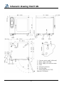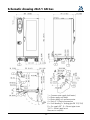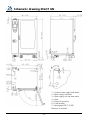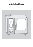
1
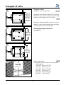
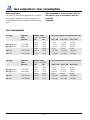
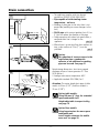
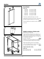
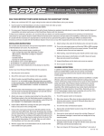
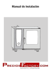
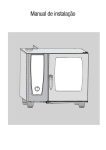
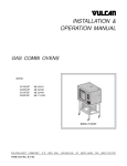
Installation Manual
Dear customer
You have a 12 month warranty from the date of your invoice.
The warranty excludes glass damage, light bulbs and sealing material as well as damage caused by
improper use, maintenance, repair by untrained/unqualified personnel and scaling of components
Quote in the event of a query:
Dealer
Appliance model:
Appliance no.:
______________________________________
Installer
Set to gas type:
______________________________________
Your appliance was checked by:
______________________________________
We reserve the right to make technical changes in the interest of progress!
-2-
Safety instructions
Warning
Incorrect installation, adjustment, alteration, service or
maintenance can cause property damage, injury or death. Read the
installation operating and maintenance instructions thoroughly before
installing or servicing this equipment.
Warrenty service repairs shoud only be carrled our by approved service
partners.
For your safety
Do not store or use gasoline or other flammable vapors or liquids in the
vicinity of this or any other appliance.
What to do in the event of danger or if you smell gas:
- Shut the gas supply immediately
- Do not touch any electric control elements
- Make sure the area is well ventilated
- Avoid naked flames or sparking
- Use an external telephone to notify the appropriate gas supplier
immediately (if the gas supplier is unavailable call the relevant fire
station).
RESET GAS
rES
„RESET“ (only gas units)
In case of a mulfunction in the burner system „RESET GAS“ or “rES”
(depends on the model)
is indicated. After 15 seconds additionally an acoustic signal is coming
up. By pressing indication „RESET GAS“ automatically a new ignition
sequence is started. If after 15 seconds the indication „RESET GAS“-is
not coming up again, then the flame is burning and the unit is ready for
use.
If the indication is still coming up even after starting the sequence
several times, then the after service has to be informed!
-3-
Table of content
Attention:
The named standards are valid for Germany. In all other countries follow the local standards
and valid instructions. Damages based on installation not complying with the directives given
hereunder are not covered by warranty terms.
Check for any transport damage.
Should there be any signs of transport damage, inform your dealer/freight forwarder
immediately! Remove all cartons, packing materials, documents, etc. from the interior
cabinet.
List of contents
Safety instructions
3
Transport of units
5
Minimum clearance
6
Installation table units
7
Installation floor units
8
Leveling mobile oven racks
9
Electrical connection
10 - 11
Water connection / Water filter selection
12 - 13
Gas connection / Gas consumption
14 - 16
Drain connection
17
Ventilation, technical data, heat emission
18
Options
19 - 21
Connection datas
22
Conversion tables
23
Schematic drawing
24 - 35
-4-
Transport of units
Transport of units
Transport of units using a pallet
1
6x1/1 GN:
920mm/36 1/4"
6x2/1 GN:
1120mm/44 1/8"
10x1/1 GN:
920mm/36 1/4"
10x2/1 GN:
1120mm/44 1/8"
pic. 1,2
Transport of units without a pallet, 20x1/1 GN and
20x2/1 GN units only. Put a piece of wood between
pallet jack and left guide rail of the trolley
pic. 3
Remove all containers/mobile oven racks from the
cabinet. For floor model, remove corner mountings
from the pallet. Take unit off the pallet.
2
Observe the weight of the units:
see page 18
20x1/1 GN:
950mm/37 1/2"
20x2/1 GN:
1150mm/45 1/4"
3
20x1/1 GN:
920mm/36 1/4"
20x2/1 GN:
1140mm/45"
4
20x1/1 GN /
20x2/1 GN:
1900mm/75"
/1GN)
X (6x1/1 - 20x2
Observe door height
pic. 4
X= Required door width when transporting units
without pallet:
6x1/1GN 840 mm (33 1/8”)
6x2/1GN 1040 mm (41”)
10x1/1GN 840 mm (33 1/8”)
10x2/1GN 1040 mm (41”)
20x1/1GN 920 mm (36,1/4”)
20x2/1GN 1140 mm (45“)
-5-
Recommended minimum clearance
Minimum clearance left/ right/ rear 50 mm (2”)
(except floor models).
pic. 1
1
50mm/2"
50mm/2"
50mm/2"
On floor models (20x1/1 GN and 20x2/1 GN) there
must be a minimum clearance of 500 mm (approx
20”) on the left side of the unit, for installing the
power cable
Minimum clearance when there are heat sources
on the left-hand side is 350 mm (14”).
pic 2
Attention: A safety shut down can occur if
the ambient temperature on the
left hand side of the unit is too
high.
2
Option:
Heat shield see page 19
We recommend a distance of 500 mm (20”) on the
left hand side of the unit for carrying out
maintenance work.
pic. 3
‡ 350mm
14"
3
50mm/2"
Warning:
The units must only be installed in frost-free rooms.
500mm/20"
50mm/2"
-6-
Installation type 6x1/1, 6x2/1, 10x1/1, 10x2/1 GN
If Gas units are installed on a table or on the
kitchen floor (combi duo) then:
a) the fixing plate (part number: 12.00.256) must
be fitted to the units leg
b) the plate must be fitted to the surface using
either screws and dowels or studs and nuts or
the special adhesive.
pic. 1
Attention: The center height of the drain pipe is
63 mm (2 1/2”). When installing combi duo
obserev the drain height of the bottom unit.
1
99mm (3 7/8”)
2
Option:
Using 150 mm (5 7/8”) legs and
height adjustable transport trolley
for extended space underneath unit.
See page 19
A 6x1/1 /10x1/1 GN: 745,5mm (29 3/8")
6x2/1 10x2/1 GN: 965,5mm (38")
A
64,5mm
2 5/8"
64,5mm
2 5/8"
+
_ 10mm
5006.0213
3
Stands for gas appliances must be fixed to the
floor using the fixing set supplied with the unit
either with screws and dowels, or with the special
adhesive supplied.
pic. 2
Electrical appliances: Fixing set is not included
in the scope of supply, but may be ordered under
part no.: 8700.0317.
pic. 2
Slide the stand into the fixing brackets and level it.
+
_ 10mm
Place the unit on the stand. The feet of the unit
must be secured by means of the locating pins of
the stand
pic. 3
Ensure that the unit is level
4
pic. 4
Attention: When Installing a Combi Duo observe
the height of the drain pipe
-7-
Installation Typ 20x1/1 GN, 20x2/1 GN
Installation type 20x1/1 GN, 20x2/1 GN
Ensure that the unit is level
1
pic. 1
Fix the floor locks, (supplied with the fixing set) to
the floor with either screws and pins or with the
special adhesive.
pic. 2
Next slide the unit into the floor locks
pic. 2
The mobile oven rack must be level when
standing inside the unit
pic. 3
2
Attention: Observe height of the drain pipe
+
_ 10mm
Option:
Using leg extension for more space
underneath unit.
Install height extension for mobile
oven rack see page 20
A 20x1/1 GN: 732,5 mm / 28 7/8"
20x2/1 GN: 937,5 mm / 37"
A
64,5mm
2 5/8"
64,5mm
2 5/8"
5006.02
13
3
-8-
Leveling mobile oven racks 20x1/1 and 20x2/1 GN
If the floor is not level, an access ramp (not
supplied) will be required. The incline must not
exceed 4°.
pic. 1,2
1
Option:
Access ramp see page 20
If there is a drain grill in front of the floor unit, a
ramp should be placed over it to enable the mobile
oven rack to be used.
pic. 3
2
max 4°
3
xxxxxxx
-9-
Electrical connection
1
5 mm
2
L
1 L
2 L
3 N
3
4
Attention:
Observe local regulations and standards
during installation
Common information see next page
Electrical units
• Each appliance requires an independent fused
power supply line
• A permanent electrical connection must be
provided for the units.
• Table units (6X1/1 GN - 10X2/1 GN) are
equipped with a power cable, which is directly
connected to the main contactor. The cable
comes without plug and is approx. 2,5 m (8 ft)
long.
• Floor units 20X1/1 GN and 20X2/1 GN are
delivered without power cable
• The main contactor (table units) and the main
terminals (floor models) are located in the
electrical compartment and are accessible after
removing the left side panel.
pic. 1/2
Gas units
• We recommend an independent fused power
supply line.
• All units are equipped with a power cable
without plug, approx.2,5 m (8 ft) long.
• The main terminals are located in the electrical
compartment and are accessible after removing
the left side panel.
pic. 1/2
• Unit should be connected to a fused spur,
observe local electrical reculations
• Attention!
Observe polarity of the mains!
No burner function with wrong polarity!
• Colour coding of the power cable:
yellow/green = earth, blue = Neutral
brown or black = Phase L1 (L2)
Gas and electrical units
• The stud for the earth bonding is located on the
bottom side, underneath the control panel.
Connect the wire for the earth bonding
to this stud.
pic. 3/4
- 10 -
Electrical connection
Common information
• Follow the installation instructions and the
information on the rating plate when connecting
the unit.
• Comply with all local regulations and standards!
• We recommend an independent fused power
supply line for each appliance.
• We recommend the use of an earth leakage
circuit breaker (30mA).
• On-site installation: provide accessible all-pole
disconnection device with a minimum of a 3 mm
contact gap.
• The wiring diagram can be found in a bag on the
inner side of the left side panel.
• Special voltages available on request.
• The cross-section of the power cables must be
based on the current consumption and on local
regulations.
• Applicable standards: EN 60335, IEC 335
• For electrical connection data, see page 22:
• Before disconnecting or reconnecting unit. Ensure
electrical supply is isolated.
For appliance connections, precise
dimensions and connection points, see
pages 24 and following.
Power cable :
• The exchange of the power cable may only be
carried out by the manufacturer, his service
agents or similar qualified personal
Electrical units
• Connect an H07RN-F supply cable (minimum),
tighten the cable gland and the strain relief
• Connect the supply as follows:
Grey terminal:
L1, L2, L3 (non-phase-sequence-dependent)
Blue terminal: Neutral (only 3N AC)
Yellow/green terminal: Earth connection
Gas:
• Units the power cable has to be exchanged a
power cable with the following minimum quality
has to be used:
H05 RN-F 3x2,5 mm2
•If the gas unit (20x1/1 / 20x2/1 GN) is protected
by means of a safety cut-out it must observe that
this cut-out is at least of characteristic “C”.
- 11 -
Water connection / Selection of water filter
Legend to water connections:
1 = Common water supply 3/4”
cold water 30°C/86°F
In case of split water connection
2 = Cold water, 30°C/86°F, connection 3/4”
(quenching)
3 = Treated water connection 3/4”
(steam generator, moistening, hand shower,
max 60°C/140°F)
Floor models
pic. 1
Table models electric
pic. 2
Table models gas
pic. 3
1
3
1
2
• Install individual shut-off valve for each appliance
• Rinse the water supply lineprior to connection to
the unit!
• Connected water pressure must be in the range
150 kPa - 600 kPa,recommended 300 kPa
pic.4
2
3
2
Average total water consumption is as follows
(values excluding usage of hand shower)
Unit size:
6x1/1 6x2/1 10x1/1 10x2/1 20x1/1 20x2/1
12,0 l/h 32 l/h 25,2 l/h 41,4 l/h 49,8 l/h 60,0 l/h
1
Note: The manufacturer recommends a preventive
check of your equipment 6 months after
installation to determine actual scvale
build up. This should be done by a trained
technician.
3
2
3
1
Water treatment:
For filter selection see next page
In most cases it is not necessary to install a filter or
water treatment for water supply. The integrated
SC-automatic changes the water in the steam
gen-erator at regular intervals automatically.
However under certain water conditions different
filter applications (A, B, C, D below) might improve
equipment performance
- 12 -
Selection of water filter
Please consult your local water supply board
for advise on chlorine (Cl2), chlorid (Cl-) and
hardness of the water
A)Particle filter
pic. 4/5
When the water contains sand, iron particles or
suspended matter, we recommend a 5-15 µm
(micro meter) particle filter:
B)Active carbon filter
pic. 4/5
When the level of chlorine (Cl2) in the water
exceeds 0.2 mg/l (= ppm) (information available
from the water company), an active carbon filter
should be installed.
Filter capacity:
Average treated water consumption is as follows
(values excluding usage of hand shower)
6x1/1 6x2/1 10x1/1 10x2/1 20x1/1 20x2/1
3,0 l/h 8 l/h 6,3 l/h 10,4 l/h 12,5 l/h 15,0 l/h
Important for filter connection:
Water supply hose / pipe size 1/2” minimum
Connection to filter : 3/4”
Should a combination of filter be installed the
sequence A-B-C-D should be observed in flow
direction as shown in pic. 4 below.
C)Complete De-Ionization
pic. 4/5
When the water has a chloride Cl- concentration
above 150 mg/l (= 150 ppm), a complete
deionization system should be installed to avoid
corrosion.
Note: Make sure a remaining conductivity of
50 µS/cm (micro Siemens) remains in the water.
D)Water softener:
pic. 4/5
A water softener is recommended when a high
level of scale (not containing chloride) is
experienced. Systems recommended: H+ Ion
Exchanger or Kleensteam. Sodium ion exchangers (as used in dishwashers) must not be used.
4
30°C/86°F
300 kPa
43,5 psi
F
I
L
T
E
R
300 kPa
43,5 psi
max. 60°C/140°F
30°C/86°F
300 kPa
43,5 psi
Amongst others the following filter manufacturers
offer adequate filter applications:
Britta, Cuno, Everpure.
Important for treated water connection:
Split the water supply to standard and treated
water connection for each unit to exteno filter
capacity!
Remove T-connection at water inlet
pic. 1/2/3
Connect cold untreated water to inlet position “2”
Connect treated water to inlet position “3”
2
5
R3/4"
150-600kpa
21,75-87 psi
3/4"
1/2"
1/2"
A
B
C
D
3/4"
max. 60°C
max. 140°F
- 13 -
3
150-600kpa
21,75-87 psi R 3/4"
Gas connection
1
6x1/1 GN: 3/4"
6x2/1 GN: 3/4"
10x1/1 GN: 3/4"
10x2/1 GN: 3/4"
5
RATIONAL
! mbar
6
2
20x1/1 GN: 3/4"
20x2/1 GN: 3/4"
RATIONAL
! mbar
7
3
4
182 mm
7 1/4"
- 14 -
Gas connection
Important!
To ensure that the burner settings made at the factory conform with the actual installation conditions, the
waste gas (C0, C02) from the steam and hot-air burners must be analysed during commissioning. The
corresponding values must be documented inside the unit. If the undiluted C0 values are above 1000 ppm,
the burner settings must be checked and if necessary adjusted by engineers trained and certified by the
company.
Comply with local gas authority regulations!
Follow installation instructions!
• Check that the gas type supplied is suitable for
the unit.
• The diameter of the pipe must comply with local
regulations
• External thread of gas connection:
pic. 1,2
• Gas stop valve supplied for each unit.
• Gas connection with gas outlet socket is
possible.
• All gas supply connectors must comply with local
regulations.
• The unit must be secured against movement.
• Check the gas supply line for leakage.
pic. 3
Attention:
• The unit is only to be connected to the gas
supply by a locally approved gas installer. It is
vital to ensue that the gas connection pipes as
well as the connection pipes for the associated
gas metering systems match the stipulated pipe
widths.
• If the flow pressure deviates from the specified
flow pressure (see table), inform the gas authorities. If the flow pressure of natural gas exceeds
30 mbar
(12,04 in w. c.), the unit must not be switched
on and the gas supply must be disconnected.
• Attention: The gas parts are designed for a maximum flow pressure of 65 mbar (26,09 in w. c.)
Type B13, B23 gas unit
B13 Ambient-air-dependent gas-powered cooking
range with fan assisted burners with exhaust
collector. Valid for all units.
B23 Ambient-air-dependent gas-powered cooking
range with fan assisted burners without
exhaust collector. Total nominal heat load
>14 KW (all except 6x1/1 GN).
• Automatic direct ignition with ignition monitor.
Installation of draft diverter
pic. 4
The draft diverter is not shipped with the unit, but
can be ordered under the following part numbers:
Unit size:
6x1/1 GN
Art.-No.: 70.00.356
6x2/1 GN
Art.-No.: 70.00.359
10x1/1 GN
Art.-No.: 70.00.348
10x2/1 GN
Art.-No.: 70.00.349
20x1/1 GN
Art.-No.: 70.00.352
20x2/1 GN
Art.-No.: 70.00.343
Gas exhaust system
• Check that gas exhaust pipes are leakproof, in
accordance with local regulations
• Waste gas pipes of aluminium or other materials
which are not resistant to temperatures up to
200°C should not be used because of the high
waste gas temperatures!
Gas exhaust system can be connected to the
following:
(observe your local regulations)
1. Extractor hood
pic. 5
2. Fan roof
pic. 6
3. Directly into the flue
pic. 7
- 15 -
Gas connection / Gas consumption
Room ventilation
The rooms in which these appliances are installed
must be well ventilated, in order to prevent an
unacceptable build-up of harmful combustion products.
We recommend to service the gas units at
least once a year in accordance with the
specified
standards.
Gas consumption
Gas type
Required
flowpressure
Nat. gas H G20
Nat. gas L G25
18-25 mbar
20-30 mbar
LPG G30
LPG G31
25-57,5 mbar
25-57,5 mbar
Gas type
Required
flowpressure
Nat. gas H G20
Nat. gas L G25
18-25 mbar
20-30 mbar
LPG G30
LPG G31
25-57,5 mbar
25-57,5 mbar
Wobbe index
(15°C, 1013mbar)
Wi
Ws
MJ/m3
MJ/m3
45,67
50,72
37,38
41,52
MJ/m3
MJ/m3
80,58
87,33
74,75
81,19
max. consumption on nominal heat load
Wobbe index
(15°C, 1013mbar)
Wi
Ws
MJ/m3
MJ/m3
45,67
50,72
37,38
41,52
MJ/m3
MJ/m3
80,58
87,33
74,75
81,19
max. consumption on nominal heat load
- 16 -
6x1/1 GN
11 kW
1,2 m3/h
1,4 m3/h
12 kW
1,01 kg/h
1,04 kg/h
10x2/1 GN
32 kW
3,4m3/h
3,9 m3/h
34 kW
2,86 kg/h
3,01 kg/h
6x2/1 GN
21,5 kW
2,3 m3/h
2,6 m3/h
23 kW
1,93 kg/h
2,03 kg/h
20x1/1 GN
43 kW
4,6 m3/h
5,3 m3/h
46 kW
3,86 kg/h
4,05 kg/h
10x1/1 GN
21,5 kW
2,3 m3/h
2,6 m3/h
23 kW
1,93 kg/h
2,03 kg/h
20x2/1 GN
64 kW
6,8 m3/h
7,9m3/h
67 kW
5,63 kg/h
6,03 kg/h
Drain connection
1
250300mm
min. 3° / 5%
Ø 50mm
max. 1m
2
• The appliance complies with the relevant
regulations (DVGW, SVGW, KIWA, WRC)
• Pipe capable of withstanding steam
temperature - no hoses
• Welding of drain pipe to the units drain is not
permissible (welding can cause damages to the
unit)
• DN 50 pipe with constant gradient (min. 5% or
3°); do not reduce the diameter of the pipe.
• Fixed connection with odour lock permissible; a
ventilated drain line is integral to the
appliance
pic. 1,2
• Where there is an existing floor drain without air
trap, a clear outflow of 2 cm (1”) must be
provided.
pic. 3
Option:
For reduction of steam escape via the
ventilation pipe a condensate
collector or an additional ascending
pipe can be used. See page 21
min. 3° / 5%
Ø 50mm
max. 1m
3
Note drainage dimensions: short-term pumped
discharge volume of steam generator 0.7 l/sec
(0,18 gal/sec.)
• Average waste water temperature: 65°C
• Applicable standard: DIN 1986, Part 1
Attention: The center height drain pipe of table
models is 63 mm (2 1/2”) and floor models is
70 mm (2 7/8”).
Option table models:
Using 100 mm (4”) legs for extended
space underneath unit.
Height adjustable transport trolley,
see page 19
Option floor models:
Using leg extension for more space
underneath unit.
Install height extension for mobile
oven rack see page 20
- 17 -
Ventilation, technical data, heat emission
Ventilation:
An exhaust hood is not essential. If one is fitted, bear the following points in mind:
• Comply with all local regulations and standards;
• The hood should project 300-500 mm (1-1,6 ft) in front of the appliance;
• Install a grease filter in the projecting part of the hood;
• An exhaust hood is available as an option for 6x1/1 - 20x1/1 GN units.
• For installation of the hood, please follow the instruction of the corresponding installation manual
Technical data:
Noise emission level:
<70dBA
Hoseproofness:
IPX5
Heat emission:
Electrical units: 6x1/1 GN
latent:
2.143 kJ/h
sensible:
2.727 kJ/h
6x2/1GN
4.167 kJ/h
5.000 kJ/h
10x1/1 GN
3.529 kJ/h
4.615 kJ/h
10x2/1 GN
6.667 kJ/h
9.474 kJ/h
20x1/1 GN
7.200 kJ/h
9.000 kJ/h
20x2/1 GN
12.500 kJ/h
14.286 kJ/h
Gas units:
latent:
sensible:
6x2/1GN
4.167 kJ/h
5.000 kJ/h
10x1/1 GN
3.529 kJ/h
4.286 kJ/h
10x2/1 GN
6.667 kJ/h
9.231 kJ/h
20x1/1 GN
7.200 kJ/h
8.780 kJ/h
20x2/1 GN
11.583 kJ/H
13.636 kJ/H
6x1/1 GN
2.143 kJ/h
2.571 kJ/h
Weight of electric units:
Units with “touch screen”:
6 x 1/1 GN: 110,0 kg
6 x 2/1 GN: 142,5 kg
10 x 1/1 GN: 135,5 kg 10 x 2/1 GN: 182,0 kg
20 x 1/1 GN: 258,0 kg 20 x 2/1 GN: 332,0 kg
Units without “touch screen”
6 x 1/1 GN: 99,0 kg
6 x 2/1 GN: 133,0 kg
10 x 1/1 GN: 124,5 kg 10 x 2/1 GN: 175,5 kg
20 x 1/1 GN: 251,5 kg 20 x 2/1 GN: 326,0 kg
Weight of gas units:
Units with “touch screen”:
6 x 1/1 GN: 126,0 kg
6 x 2/1 GN: 168,0 kg
10 x 1/1 GN: 154,5 kg 10 x 2/1 GN: 198,0 kg
20 x 1/1 GN: 286,0 kg 20 x 2/1 GN: 370,5 kg
Units without “touch screen”
6 x 1/1 GN: 121,0 kg
6 x 2/1 GN: 158,5 kg
10 x 1/1 GN: 148,0 kg 10 x 2/1 GN: 189,5 kg
20 x 1/1 GN: 261,0 kg 20 x 2/1 GN: 369,5 kg
Right of technical modifications reserved.
- 18 -
Option
1
Heat shield
Unit size:
6x1/1GN
10x1/1GN
6x2/1GN
10x2/1GN
20x1/1GN
20x2/1GN
Art.-No.: 60.70.390
Art.-No.: 60.70.391
Art.-No.: 60.70.392
Art.-No.: 60.70.393
Art.-No.: 60.70.394
Art.-No.: 60.70.395
If minimum reuired the distance can not be
maintained on the left sde of the unit a heat shield
will help to reduce the heat stress to the unit
pic 1
The heat shield must be fitted to the left side panel
of the unit.
2
Height extension of table units.
3
(6x1/1 GN up to 10x2/1GN)
Should the distance between floor and bottom of
table units be too low (e.g. when installing combi
duo), then the standard lower parts of the legs can
be replaced by longer legs.
Art.-No.: 12.00.224
pic. 2
Attention: In this case the height of the upper rail
in the cooking cabinet exceeds 1600 mm (63”)
When using mobile oven racks and transport
trollies the height difference can be compensated
by a higt adjustable transport trolley.
pic. 3
Height adjustable trolley:
Unit size:
6x1/1 and 10x1/1 GN
Art.-No.: 60.60.188
6x2/1 and 10x2/1 GN
Art.-No.: 60.70.160
- 19 -
Option
1
2
3
Foot extension for floor units
Art.-No.: 60.21.179
Should the the distance be too low between floor
and bottom of floor units , foot extensions for
floor units can be used
pic 1
Attention: In this case the height of the upper rail
exceeds 1600 mm (63”).
When using these foot extensions a height
compensation of the mobile oven rack must be
carried out by adding an additional frame.
pic. 2
20x1/1GN
Art.-No.: 60.21.184
20x2/1GN
Art.-No.: 60.22.184
Ramp for mobile oven rack floor
models
20x1/1GN
Art.-No.: 60.21.080
20x2/1GN
Art.-No.: 60.22.181
If the floor underneath the unit is not level the
mobile oven rack ramp can level out this
uneveness. The adjustment range of the legs is
between +/- 10 mm .
pic. 1
- 20 -
Option
Under critical installation condition (i. e. Installation
in front cooking areas) the steam escape via the
vent pipe can be elimnated by installing
a condensation collector (8710.1309)
pic. 1
1
Also for reducing the steam escape at the drain
pipe an additional vent pipe can be fitted to the
drain pipe. In this extra vent pipe holes must be
drilled where air is sucked in and condensates the
steam
pic 2
2
Interfaces
a) A serial interface (RS232) is not standard, but
can be retrofitted into all units.
Unit size
6x1/1GN - 10x2/1GN
Art.-No.: 87.00.006
20x1/1GN - 20x2/1GN
Art.-No.: 87.00.007
b) Units with touch screen are equipped with USB
interface as a standard.
- 21 -
Connection datas
P = kW
I=A
6x1/1 6x2/1 10x1/1 10x2/1 20x1/1 20x2/1 6x1/1 6x2/1 10x1/1 10x2/1
2 AC 208V
2 AC 240V
3 AC 200V 10,1
19,5
17,5
34,5
34,5
57,5
24
53,5
48
100
3 AC 208V
10
21
19
37
37,5
62
28
58,5
53
102,5
3 AC 230V
10
21
19
37k
37
62
25
53
48
93
3 AC 240V
10
21
19
37
37,5
62
24
51
46
89
3 NAC 400V 10
21
19
37
37
62
14,5
30,5
27,5
53,5
3 AC 400V
10
21
19
37
37
62
14,5
30,5
27,5
53,5
3 NAC 415V 10,5
22,5
20,5
40,5
40,5
66,5
14,5
31,5
28,5
56,5
3 AC 440V
10
21
19
37
37
62
13
28
25
49
3 AC 480V
10
21
19
37
37
62
12
25,5
23
44,5
20x1/1
100
104
93
90,5
53,5
53,5
56,5
49
44,5
20x2/1
166
172
156
149,5
89,5
89,5
92,5
81,5
75
∅ mm2
I=A
6x1/1 6x2/1 10x1/1 10x2/1 20x1/1 20x2/1 6x1/1 6x2/1 10x1/1 10x2/1 20x1/1 20x2/1
2 AC 208V
2 AC 240V
3 AC 200V
35
63
63
100
100
200
4
10
10
25
35
95
3 AC 208V
30
60
60
110
110
175
4
10
10
25
35
95
3 AC 230V
32
63
63
100
100
200
4
10
10
16
25
50
3 AC 240V
30
60
60
110
110
175
4
6
6
16
25
50
3 NAC 400V 16
32
32
63
63
100
2,5
4
4
6
10
25
3 AC 400V
16
32
32
63
63
100
2,5
4
4
6
10
25
3 NAC 415V 16
32
32
63
63
100
2,5
4
4
6
10
25
3 AC 440V
16
32
32
63
63
100
2,5
4
4
6
10
25
3 AC 480V
15
30
25
50
50
80
2,5
4
4
6
6
16
P = kW
1NAC 100V
1NAC 110V
1NAC 120
1NAC 127V
1NAC 220V
1NAC 230V
1NAC 240V
2 AC 200V
2 AC 208V
I=A
6x1/1 6x2/1 10x1/1 10x2/1 20x1/1 20x2/1 6x1/1 6x2/1 10x1/1 10x2/1 20x1/1 20x2/1
0,3
0,350,35
0,45
0,7
1
3
3,53,5
4,5
7
10
0,3
0,35
0,35
0,45
0,7
1
2,7
3,2
3,2
4,1
6,4
9,1
0,3
0,35
0,35
0,45
0,7
1
2,5
2,9
2,9
3,7
5,8
8,3
0,3
0,35
0,35
0,45
0,7
1
2,4
2,8
2,8
3,5
5,5
7,8
0,3
0,35
0,35, 0,45
0,7
1
1,4
1,6
1,6
2,1
3,6
4,5
0,3
0,35
0,35
0,45
0,7
1
1,3
1,5
1,5
2,0
3,5
4,4
0,3
0,35
0,35
0,45
0,7
1
1,2
1,4
1,4
1,9
3,3
4,2
0,3
0,35
0,35
0,45
0,7
1
1,5
1,8
1,8
2,3
4,0
5,0
0,3
0,35
0,35
0,45
0,7
1
1,4
1,7
1,7
2,2
3,8
4,8
- 22 -
Conversion tables
1 °dH
1 °f
1 °e
1 ppm
1 mmol/l
1 gr/gal (US)
1 mval/kg
°dH
1
0,56
0,8
0,056
5,6
0,96
2,8
°f
1,79
1
1,43
0,1
0,001
1,71
5,0
1 °dH:
10,00 mg CaO/kg
(Germany) 17,86 mg CaCO3/kg
7,14 mg Ca2+/kg
1 °f :
5,60 mg CaO/kg
(France)
10,0 mg CaCO3/kg
4,00 mg Ca2+/kg
1 °e :
8,01 mg CaO/kg
(GB)
14,3 mg CaCO3/kg
5,72 mg Ca2+/kg
kPa
0,1
0,2
0,3
0,4
0,5
0,6
0,7
0,8
0,9
1
1,2
1,4
1,6
1,8
2
2,5
3
3,5
mbar
1
2
3
4
5
6
7
8
9
10
12
14
16
18
20
25
30
35
psi
0,0147
0,0294
0,0441
0,0588
0,0735
0,0882
0,1029
0,1176
0,1323
0,147
0,1764
0,2058
0,2352
0,2646
0,294
0,3675
0,441
0,5145
°e
1,25
0,70
1
0,07
0,0007
1,20
3,5
ppm
17,9
10,0
14,32
1
100
17,1
50
mmol/l
0,1783
0,1
0,14
0,01
1
0,171
0,5
gr/gal(US)
1,044
0,584
0,84
0,0584
0,00058
1
2,922
mval/kg
0,357
0,2
0,286
0,02
2
0,342
1
1 ppm :
(USA)
0,56 mg CaO/kg
1 gr/gal : 9,60 mg CaO/kg
1,0 mg CaCO3/kg
(USA)
64,8 mg CaCO3/gal
0,40 mg Ca2+/kg
17,11 mg CaCO3/kg
1 mmol/l :
56,00 mg CaO/kg
6,85 mg Ca2+/kg
(chem. conz.) 100,0 mg CaCO3/kg
39,98 mg Ca2+/kg
1 mval/kg : 28,00 mg CaO/kg
(Milliäquivalent) 50,0 mg CaCO3/kg
19,99 mg Ca2+/kg
inch/wc
0,4014
0,8028
1,2042
1,6056
2,0070
2,4084
2,8098
3,2112
3,6126
4,0140
4,8168
5,6196
6,4224
7,2252
8,0280
10,0350
12,0420
14,0490
kPa
4
4,5
5
5,5
6
6,5
7
7,5
8
8,5
9
9,5
10
20
30
40
50
100
- 23 -
mbar
40
45
50
55
60
65
70
75
80
85
90
95
100
200
300
400
500
1000
psi
0,588
0,6615
0,735
0,8085
0,882
0,9555
1,029
1,1025
1,176
1,2495
1,323
1,3965
1,47
2,94
4,41
5,88
7,35
14,7
inch/wc
16,0560
18,0630
20,0700
22,0770
24,0840
26,0910
28,0980
30,1050
32,1120
34,1190
36,1260
38,1330
40,1400
80,2800
120,4200
160,5600
200,7000
401,4000
Schematic drawing 6x1/1 GN
1 = Common water supply (cold water)
2 = Water supply, cold water
3 = Water supply, soft and warm water
4 = Drain
5 = Electrical connection
6 = Earth bonding
7 = Venting pipe DN 50 (2)
Measures in mm(inch)
- 24 -
Schematic drawing 6x1/1 GN Gas
1 = Common water supply (cold water)
2 = Water supply, cold water
3 = Water supply, soft and warm water
4 = Drain
5 = Electrical connection
6 = Earth bonding
7 = Venting pipe DN 50 (2)
8 = Gas supply 3/4”
9 = Exhaust pipe steam
10 = Exhaust pipe hot air
Measures in mm(inch)
- 25 -
Schematic drawing 6x2/1 GN
1 = Common water supply (cold water)
2 = Water supply, cold water
3 = Water supply, soft and warm water
4 = Drain
5 = Electrical connection
6 = Earth bonding
7 = Venting pipe DN 50 (2)
Measures in mm(inch)
- 26 -
Schematic drawing 6x2/1 GN Gas
1 = Common water supply (cold water)
2 = Water supply, cold water
3 = Water supply, soft and warm water
4 = Drain
5 = Electrical connection
6 = Earth bonding
7 = Venting pipe DN 50 (2)
8 = Gas supply 3/4”
9 = Exhaust pipe steam
10 = Exhaust pipe hot air
Measures in mm(inch)
- 27 -
Schematic drawing 10x1/1 GN
1 = Common water supply (cold water)
2 = Water supply, cold water
3 = Water supply, soft and warm water
4 = Drain
5 = Electrical connection
6 = Earth bonding
7 = Venting pipe DN 50 (2)
Measures in mm(inch)
- 28 -
Schematic drawing 10x1/1 GN Gas
1 = Common water supply (cold water)
2 = Water supply, cold water
3 = Water supply, soft and warm water
4 = Drain
5 = Electrical connection
6 = Earth bonding
7 = Venting pipe DN 50 (2)
8 = Gas supply 3/4”
9 = Exhaust pipe steam
10 = Exhaust pipe hot air
Measures in mm(inch)
- 29 -
Schematic drawing 10x2/1 GN
1 = Common water supply (cold water)
2 = Water supply, cold water
3 = Water supply, soft and warm water
4 = Drain
5 = Electrical connection
6 = Earth bonding
7 = Venting pipe DN 70 (2 3/4)
Measures in mm(inch)
- 30 -
Schematic drawing 10x2/1 GN Gas
1 = Common water supply (cold water)
2 = Water supply, cold water
3 = Water supply, soft and warm water
4 = Drain
5 = Electrical connection
6 = Earth bonding
7 = Venting pipe DN 70 (2 3/4)
8 = Gas supply 3/4”
9 = Exhaust pipe steam
10 = Exhaust pipe hot air
Measures in mm(inch)
- 31 -
Schematic drawing 20x1/1 GN
1 = Common water supply (cold water)
2 = Water supply, cold water
3 = Water supply, soft and warm water
4 = Drain
5 = Electrical connection
6 = Earth bonding
7 = Venting pipe DN 70 (2 3/4)
Measures in mm(inch)
- 32 -
Schematic drawing 20x1/1 GN Gas
1 = Common water supply (cold water)
2 = Water supply, cold water
3 = Water supply, soft and warm water
4 = Drain, 5 = Electrical connection
6 = Earth bonding7 = Venting pipe DN 70 (2 3/4)
8 = Gas supply 3/4”, 9 = Exhaust pipe steam
10/11 = Exhaust pipe hot air
Measures in mm(inch)
- 33 -
Schematic drawing 20x2/1 GN
1 = Common water supply (cold water)
2 = Water supply, cold water
3 = Water supply, soft and warm water
4 = Drain
5 = Electrical connection
6 = Earth bonding
7 = Venting pipe DN 70 (2 3/4)
Measures in mm(inch)
- 34 -
Schematic drawing 20x2/1 GN Gas
1 = Common water supply (cold water)
2 = Water supply, cold water
3 = Water supply, soft and warm water
4 = Drain, 5 = Electrical connection
6 = Earth bonding7 = Venting pipe DN 70 (2 3/4)
8 = Gas supply 3/4”, 9 = Exhaust pipe steam
10/11 = Exhaust pipe hot air
Measures in mm(inch)
- 35 -
UK
80.01.017 · V-01 · MediaDesign and Services · Ad · 04/04