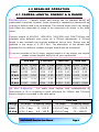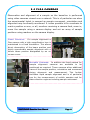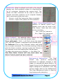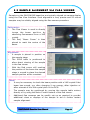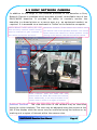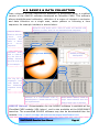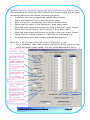
1
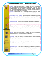
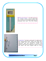
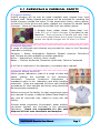
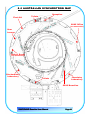
Small / Wide Angle X-ray
Scattering Beamline
(SAXS/WAXS)
User Manual
Version 1.1 21/01/2009
SAXS/WAXS User Manual
TABLE OF CONTENTS
1.0 PERSONNEL SAFETY SYSTEM (PSS)
1.1 PSS—SEARCH & SECURE PROCEDURE
3
5
2.0 BEFORE YOUR EXPERIMENT
2.1 CEHMICALS & CHEMICAL SAFETY
6
7
3.0 USER RESOURCES (SUPPLIED)
8
4.0
4.1
4.2
4.3
BEAMLINE OPERATIONS
CAMERA LENGTH, ENERGY & Q RANGE
SAMPLE MOUTNING
SAMPLE ALIGNMENT
9
9
10
10
5.0
5.1
5.2
5.3
FLEA CAMERAS
FLEA VIEWER
SAMPLE ALIGNMENT VIA FLEA VIEWER
SONY NETWORK CAMERA
11
12
14
15
6.0 SAXS15 & DATA COLLECTION
6.1 STARTING SAXS15
6.2 DATA COLLECTION
7.0
16
17
18
AFTER INJECTION & TROUBLESHOOTING
20
8.0 TROUBLESHOOTING
21
9.0 AUSTRALIAN SYNCHROTRON MAP
22
10.0
PHONE CONTACT SHEET
SAXS/WAXS Beamline User Manual
23
Page 2
1.0 PERSONNEL SAFETY SYSTEM ( P SS )
Siren: When the search button is pressed, the siren sounds until
the search secure process is finished or aborted. There are three
different sirens: one for a search in progress, another indicating
the search is completed and a third to indicate that the search is
aborted or has timed out (45 seconds).
Strobe: Flashes when siren is sounding. Alerts all personnel that
the search procedure is in progress and to leave the hutch.
Emergency Stop Button: This button is for emergencies only.as
power will be cut to the beamline and the storage ring will dump.
Only use this button in an actual electrical or radiation emergency.
Key Interlock: Keys for unlocking cable labyrinth. If these keys
Search Point: If this button is flashing it is ready to be pressed.
If you need to secure an area and the light is not flashing check
that the double doors are closed. Also check if the labyrinth keys
are in the key interlock, and turned to the lock position.
Inside hutch
Siren: When the search button is pressed, the siren sounds until
the search secure process is finished or aborted.
Unlock: Press this button to unlock the door to enter the hutch.
Once the hutch is unlocked the search and secure procedure must
be followed to re-lock it.
Stack Lamp Legend: A quick, straightforward reference to what
the different stack lamp signals mean.
Search Point: If this button is flashing it is ready to be pressed.
If you need to secure an area and the light is not flashing check
that the doors are closed and interior search point buttons have
been pressed.
Outside hutch
SAXS/WAXS Beamline User Manual
Page 3
PSS Control Panel: All PSS functions,
i.e., shutter control, search status and
door unlocking, are displayed and may be
accessed from here. The PSS Control
Labyrinth: Provides a safe path for cabling into
the experimental hutch. Users may feed their
own cables into the end-station through the
labyrinth. Keys are required to unlock the
labyrinth and must be replaced in order to secure
the hutch. Ask user support staff for more
SAXS/WAXS Beamline User Manual
Page 4
1.1 PSS—SEARCH & SECURE PROCEDURE
Search and Secure Process:
To run the beamline, the hutches must be searched and secured/locked.
1. Enter the end-station hutch and check that no-one is present.
2. Ensure that the swing doors are closed and the sliding door is open.
3. Press the (flashing) search button by the sample table. The alarm will
sound and you now have 45 seconds to complete the search and secure.
4. Press the now flashing search button opposite the sliding doors.
5. Exit hutch and close the sliding doors. You will hear the doors lock.
The outside secure button will now start flashing.
6. Press the secure button outside the end-station hutch. The indicator
will now show orange and the end-station hutch is secure and the siren
sound will change.
If you accidentally unlock the front end optics hutch, you will lose beam.
Please contact user support staff. DO NOT enter the front end hutch.
PSS Control Panel—Overview:
Front End Shutter Control
Red = Enabled; Green = disabled
Blue = Searched
Red = Not Searched
Red = open
Green = closed
Red = Locked
Green = Unlocked
Shutter control,
press to activate
Press to Unlock
hutch (Shutter
must be closed)
Note: The touch screen of the Control Panel
requires a relatively firm touch to register.
SAXS/WAXS Beamline User Manual
Page 5
2.0 BEFORE YOUR EXPERIMENT
Prior to your arrival for your experiment at the Australian Synchrotron the
following steps must be completed liaising with the User Office. For further
information please contact the User Office [email protected]
1. Return of Experiment Authorisation Form
2. Booking Safety Training for Users (can only be completed
after return of experiment authorisation form)
3. Travel and Accommodation Requirements
1. Experiment Authorisation Form: The experiment authorisation safety
form must be returned a minimum of 1 week prior to your experiment. The
User Office must be provided with a list possible of all users who will be
attending the experiment and detailed information on all samples that you
will be bringing. User’s not on the form wont be able to have safety training,
be issued dosimeter or access card. All samples must be listed.
Please also note that if you are bringing any hazardous chemicals the relevant
OHS assessment forms MUST be filled in and relevant MSDS for those
chemicals attached otherwise ESA forms will NOT be signed off.
For
guidelines in filling out the experiment authorization form please follow the
link: http://www.synchrotron.org.au/content.asp?Document_ID=5309
2. Book Safety Training: Safety training and a test are required to access
the experimental hall, hutches and laboratories. This test must be done biannually to ensure users are up-to-date. If you have not previously used the
beamline or laboratory required for your experiment a beamline induction
must be done with the beamline scientist before access will be authorised.
Before arriving at the Australian Synchrotron review the documents below:
http://www.synchrotron.org.au/content.asp?Document_ID=5162
There is a 1-2 hour onsite safety induction to complete upon arrival at the
Australian Synchrotron. This must be arranged at least one week before your
experiment. To organize - send details of all users attending the experiment
(full name, e-mail address and contact telephone number for each team
member) to the User Office and note when you would like to do the training.
3. Travel and Accommodation: Interstate and international users may wish
to apply to the Australian Synchrotron for travel funding (see link below).
Accommodation is available for all users and will be booked by the User Office
but users must arrange/book their own flights and/or ground travel.
http://www.synchrotron.org.au/retrievemedia.asp?Media_ID=5416
In order to apply for funding from the Australian Synchrotron an application
for travel funding form must be filled in by the group spokesperson and
signed by all appropriate parties. Submission must be via scanned email (not
via post or fax) to the user office as soon as possible and well in advance of
the experiment. Australian Synchrotron travel funding will only support up to
3 people per experiment (excluding Foundation Investor allocated time).
SAXS/WAXS Beamline User Manual
Page 6
2.1 CHEMICALS & CHEMICAL SAFETY
Cryogenic Safety:
Liquid nitrogen will be may be made available upon request from local
support staff. Safety glasses and gloves will be provided for handling the
liquid nitrogen outside the hutch. In the experiment hutch, cotton gloves,
covered by nitrile gloves and safety glasses are required to handle liquid
nitrogen. Users are requested to provide their own cotton gloves.
A durable foam rubber dewar (Spear-Labs) that
holds 800 ml of liquid nitrogen is provided at the
beamline. They are easier to handle and safer than
a low profile glass Dewar and a lower thermal mass
causes less liquid nitrogen boil off when it is filled.
Chemical Supplies:
A range of chemicals and solvents are provided for users in the Chemistry
Laboratory including:
Solvents — Water, Isopropanol, Methanol, Ethanol, Acetone. Chloroform
and Toluene are also available in smaller quantities.
Acids — Hydrochloric, Sulfuric, Nitric, Acetic
Bases — Sodium Hydroxide, Potassium Hydroxide, Calcium Carbonate
A full list of chemicals in the laboratory is available upon request.
Chemical Safety and PPE:
Nitrile gloves, laboratory coats of a range of sizes and
safety glasses are provided at the chemistry
laboratory.
Personal
Protection
Equipment
is
mandatory when in the laboratory and when handling
chemicals. Users are expected to follow safe handling
procedures for their samples and when using chemicals
during sample preparation.
Before arriving at the facility for their experiment users
are required to supply a Material Safety Data Sheet for
any and all chemicals they intend to bring into the
facility.
Solvent waste containers (chlorinated; water soluble;
non-water soluble) are provided in the chemistry
laboratory. Users are responsible for the safe
disposal of their own chemicals and samples.
SAXS/WAXS Beamline User Manual
Page 7
3.0 USER RESOURCES ( SUPPLIED )
Laboratory Supplies:
The chemistry laboratory is located opposite the
SAXS/WAXS beamline and proximity badge access may be arranged through
the User Office. General glassware, glass and plastic sample preparation
containers, Kimwipes and Parafilm is available in the chemistry laboratory.
Common solvents, acids and some additional chemicals are also available,
however users are expected to provide the chemicals required for their
experiment.
For specific requirements, advice or a detailed list of the
glassware and/or chemicals available please contact local support staff.
Laboratory Equipment:
A range of equipment is
provided in the chemistry laboratory for sample
preparation and storage.
A fumehood, hotplate
stirrers, ultrasonic baths, four decimal place balances
are all available for routine sample preparation. Some
gases are available, however users should contact
support staff for any specific gas requirements prior to
their experiment.
Fridges, an oven, a hydraulic press and a diamond saw
are also provided for storage and preparation, manuals
for all equipment are also available. Additionally, a
Leica DME microscope is available in the chemistry
laboratory for all users at the synchrotron.
Sample Environments: Solid samples and liquids in capillaries (brought by
users) may be readily mounted on the beamline. Sample mounting is flexible
and users are advised to consider their requirements prior to their experiment.
Samples are mounted on a jack rated to over 200kg and precision adjustment
is facilitated in three dimensions. Stages are also available for precision
rotation and tilt control while a water bath and temperature controller is
User Lounge: A lounge has been provided for users to rest, relax and eat in,
it is located on the ground floor. Tea, coffee and mugs are freely available in
the user lounge and a vending machine is available with food and soft drink.
Fridges are also available to store food brought into the synchrotron as there is
no cafeteria at the facility. Users are requested to be considerate to others and
clean up after themselves. Food is not encouraged at the beamline
however beverages are permitted at the SAXS/WAXS beamline.
SAXS/WAXS Beamline User Manual
Page 8
4.0 BEAMLINE OPERATION
4.1 CAMERA LENGTH, ENERGY & Q RANGE
Considerations:
Camera length and energy can be changed during an
experiment if required, however, when choosing or requesting a camera set-up
a range of factors need to be considered. The camera length and X-ray energy
both effect the observable Q range of the instrument as shown in the table
below.
Camera lengths of 650/950, 1250/1550, 3000/3300 and 7000/7300mm are
available using different nose cones for a 300mm adjustment. A 330mm
length is also available but requires additional set-up time. Energy may be
selected in the range of 5—20.0 KeV. The absorption of the sample and
available flux for different incident energies should also be considered.
If you are uncertain of the Q range, camera length or X-ray energy you require
please contact support staff prior to your experiment.
650 mm
1250 mm
3000 mm
Q Max Q Min Q Max
(Å-1)
(Å-1)
(Å-1)
7000 mm
Energy
Q Min
(Å-1)
Q Min Q Max Q Min Q Max
(Å-1) (Å-1)
(Å-1)
(Å-1)
8 KeV
0.025
0.51
0.013
0.27
0.005
0.11
0.002
0.05
10 KeV
0.031
0.64
0.016
0.33
0.007
0.14
0.003
0.06
12 KeV
0.037
0.76
0.019
0.40
0.008
0.17
0.0035
0.07
15 KeV
0.047
0.95
0.024
0.50
0.010
0.21
0.0043 0.089
2θ and d-spacing:
For users more familiar with considerations of
instruments in 2θ or d-spacing a quick reference for 250mm and 7000mm
camera lengths is provided in the table below.
650 mm
7000 mm
2θ range
d-spacing range
2θ range
d-spacing range
8 KeV
0.35—7 deg
12 - 250 Å
0.03-0.67 deg
130 – 2700 Å
15 KeV
0.35—7 deg
6.5 - 135 Å
0.03-0.67 deg
70 - 1450 Å
Energy
SAXS/WAXS Beamline User Manual
Page 9
4.2 SAMPLE MOUNTING
Sample Position: The sample position, pictured to the
right, consist of an adjustable plate mounted on a jack.
The jack is rated to approximately 500 kg and is
moveable in three dimensions with 2 µm precision.
Equipment and stages may be readily mounted at the
sample position and fixed in place using the hole
pattern for 6mm bolts. For particularly large equipment
or sample environments the entire sample stage
assembly may be moved and support staff should be
contacted if this is required.
Sample Mounting: A steel breadboard is used at the sample position to allow
positioning of sample holders and allows rapid installation of different sample
mounting arrangements. Small solid samples (0.1 - 40 mm) may be readily
mounted using sample mounting plates/brackets provided on the beamline.
Additionally, samples in capillaries may be mounted vertically or horizontally in
a similar manner and a syringe pump is available if a liquid flow is required.
For larger samples or for a specific sample mounting please contact support
staff and a custom mounting can be readily arranged.
Sample Rotation, Tilt and Translation: In addition to the translation of the
sample stage a rotation stage and a 2 dimension tilt stage, rated over 100 kg,
are available to provide sample movement/alignment. Additional linear stages
rated at 90kg or 10 kg are also available for mounting on the sample stage if it
is preferable to move the sample without moving the sample stage.
4.3 SAMPLE ALIGNMENT
Sample Alignment:
Visual alignment
using the flea network cameras (detailed in
section 5.2) is the most common alignment
procedure. Samples are aligned against an
on screen cursor set at the known, tested
beam position. This procedure provides a
precision of better than 10 µm, however,
samples may also be aligned directly at the
beamline end station or by a beam scan
across a sample if required.
SAXS/WAXS Beamline User Manual
Page 10
5.0 FLEA CAMERAS
Observation and alignment of a sample on the beamline is performed
using video cameras viewed over a network. This is of particular use when
the experimental hutch is secured as sample movement, orientation and
alignment may be directly monitored. It is also possible to fix crosshairs to
mark a position on one, or all, monitors receiving a camera feed, zoom in,
move the sample using a camera display and set an array of sample
positions using markers on the camera display.
Fixed Cameras:
For sample alignment a
Flea camera with a high magnification lens is
maintained in a fixed orientation. This allows
direct observation of the beam position and
highly reproducible sample alignment with a
known beam position designated by an on
screen cursor.
Movable Cameras: In addition the fixed camera for
sample alignment cameras are available to be
positioned as required. These cameras allow additional
views of the sample position, orientation and movement
during alignment and measurement. This further
facilitates rapid sample alignment and is of particular
use for the measurement of mobile samples and for
data collection regimes including sample movement.
SAXS/WAXS Beamline User Manual
Page 11
5.1 FLEA VIEWER
Changing between multiple camera feeds, placing cursors and all other
functions of the flea cameras are controlled using the Flea Viewer program
detailed below. If necessary the Flew Viewer program may be reopened using
the flea_viewer.sav file on the desktop and Click ‘Start Video’.
Image Control and Motor
Control selection: These
buttons toggle between
control of the camera
image and control of the
sample stage.
Start / Pause Video: The video
feed from the selected Flea
camera may be started and
stopped using these buttons. If
a camera is not working check
that ‘Start Video’ is pressed.
Camera Selection: These buttons
show the names of the Flea
cameras currently available in the
Viewer. Clicking on the name of the
desired camera toggles the view to
the video feed of that camera.
Set & Clear Background: Used to set a background that will be
subtracted from the image to highlight other points of interest.
Restart Camera Button: May be used
to restart the camera feed if needed.
Camera Selection & Control: Flea cameras are designated by names, e.g.
Homer. The available cameras are shown in the top left of the window and the
displayed view is changed by clicking on the desired camera name. The
camera gain and shutter may also be adjusted. Ensure that the correct camera
is selected and video is started before making other changes or commands.
SAXS/WAXS Beamline User Manual
Page 12
Crosshairs: Green crosshairs are fixed on the present
display only. Red crosshairs remain in a fixed position
on all computers displaying the camera feed. This
allows the Red crosshairs to be used to mark the
sample and beam positions on all computer displays
while remaining outside the hutch.
‘Control + Left Click’ places the Green crosshairs
‘Control + Right Click’ places the Red crosshairs.
Image Zoom/Magnification: In
addition to manual optical zoom,
digitally zoom may be used in the
Flea Viewer. Note that this yield
poorer resolution.
‘Alt + Left Click’ zooms in.
‘Alt + Right Click’ zooms out.
Motor
Control
selected
Motor Control:
By selecting Motor Control the Flea
Viewer may be used to move the sample stage.
Once calibrated— ‘Shift + Left Click’ moves the sample
until the Red Crosshair is centered at the selected point.
To Calibrate—Click on the ‘Calibrate’ button and follow
the on screen commands. This involves marking a Fiducial
with the Green crosshair, moving to place the Fiducial in
the opposite corner and marking the Fiducial again.
To assign the motors go to Settings —> Set Motor PVs.
Flea View Motor Control will only work when the
Motor Control panel has been selected.
Motor
names
Background Subtraction:
The Flea
Viewer
may
perform
background
subtraction to highlight changes in the
image, for example the beam position. In
Image Control the Set Background button
begins background subtraction with the
current image used as the background.
The Clear Background button is used to
stop background subtraction.
SAXS/WAXS Beamline User Manual
Page 13
5.2 SAMPLE ALIGNMENT VIA FLEA VIEWER
Samples on the SAXS/WAXS beamline are typically aligned via camera display
using the Flea View interface. Such alignment is very precise and 50 micron
samples may be reliably aligned using the flea camera procedure.
Calibration:
•
The Flea Viewer is used to directly
image the beam position by
observing fluorescence from a YAG
crystal.
•
The Red, ‘Beam Cursor’ is then
placed to mark the centre of the
beam.
Alignment:
•
A sample is placed in position on
the sample stage
•
The SAXS table is positioned to
allow direct viewing of the sample
in the flea viewer
•
With the Red cursor still marking
the position of the beam the sample
stage is moved to place the desired
sample position at the crosshair.
Note:
•
It may be necessary to check the beam position with a YAG crystal if the
beam has moved, e.g. after changing X-ray energy, after injection or
after a tweak of the 2nd crystal pitch in the DCM.
•
The sample may be positioned by moving the sample table motors
directly or by using the Motor Control feature of the flea viewer.
•
Additional flea cameras can be readily set up as required to provide
additional views or displays of the sample to aid or further hasten
sample alignment.
SAXS/WAXS Beamline User Manual
Page 14
5.3 SONY NETWORK CAMERA
In addition to the range of Flea cameras provided on the beamline a Sony
Network Camera is available which provides a broad, controllable view of the
SAXS/WAXS beamline. It provides the ability to remotely monitor the
beamline in a broad picture or a narrow area, e.g. an equipment readout, as
required. It is accessed via a bookmark in Firefox on the beamline computer.
Control Button: When starting the view
from the Sony network camera Control
must be selected to gain command of
the camera movement and zoom.
Movement Controls: These buttons are used to move
the camera view in the specified direction. The central
button returns the camera to a Home position. Single
clicking in the camera view also moves the camera.
Camera View
Zoom Controls: Both the Wide and Tele
buttons and the Slider Bar control the camera
Zoom. Additionally, a box may be drawn in the
camera view to zoom on a region of interest.
Camera Control: The view and zoom of the camera may be controlled
using the online interface. The view may be adjusted using the arrows at the
left of the display while the zoom may be controlled using the buttons or by
marking out a region of interest within the camera view.
SAXS/WAXS Beamline User Manual
Page 15
6.0 SAXS15 & DATA COLLECTION
Data collection on the SAXS/WAXS beamline is performed using a modified
version of the SAXS15 software developed at ChemMat CARS. This software
allows straightforward calibration, definition of a region of interest or exclusion
and data collection as a single scan, raster pattern or following a time
sequence. An example interface is shown below.
‘Acquire’ Menu:
Used to edit the
‘Auto’
scan
sequence
and
start a Move
and
Scan
sequence.
Filename: Must
end in ###.tif,
e.g. the ‘001.tif’
ending denotes
the first scan of
a new sample.
Exposure drop down menu: Used to select the desired scan
duration or select ‘Auto’ for an automated scan sequence.
2D Image from detector
Radially averaged
data profile
The Log file is
displayed here
with details of
the
filenames,
exposure times,
etc.
Selection of a Transmission scan or
SAXS Exposure. ‘SAXS Calibrate’ is not
yet implemented.
Start Action button, used to
begin data collection once the
desired scan type is selected.
SAXS15 Manual: Documentation for the SAXS15 software is available at the
ChemMat CARS website (URL below) and is also available at the SAXS/WAXS
beamline. The unmodified SAXS15 software may also be downloaded from the
website: http://cars9.uchicago.edu/chemmat/pages/swsoftware.html
SAXS/WAXS Beamline User Manual
Page 16
6.1 STARTING SAXS15
During your experiment it may be necessary to start, or restart, the
SAXS15 software controlling the MAR detector, e.g., if the software
freezes or crashes.
To start SAXS15 follow the steps outlined below.
Ensure SAXS15, if previously running, is closed
•
Ensure IDL, if previously running, is closed
•
Open IDL using the shortcut on the desktop
•
Click to continue
•
When asked which Workspace to open click ‘OK’
In the Command Line type: saxs15id_3296, /epics
•
Select ‘No’ when asked about the run mode
•
•
Once SAXS15 is running you will need to set-up the Log File and
Parameters File in order to begin collecting data.
Follow the steps below to set up SAXS15
In the top menu go to ‘File’
•
Click on ‘Get Scan Log’
•
Find your Log File, C:\Data\Your Directory\***.log
•
Select the log file
•
In the top menu go to ‘File’
•
Click on ‘Get SAXS Parameters’
Find your Parameters File, C:\Data\Your Directory\***.sax
•
Select the sample exposure time
•
Input the sample filename
•
•
You should now be ready to collect data with SAXS15.
SAXS/WAXS Beamline User Manual
Page 17
6.2 DATA COLLECTION
Detector & Beamstop Alignment: Positioning and alignment of the
detector and beam stop will be performed by the local contact during the
initial setup of an experiment. A mask to exclude the region covered by the
beamstop may be made in the SAXS15 software and masks may also be
made to restrict the data to a specific region of interest. Instructions for these
masks may be found in the SAXS15 manual and local staff will also be able to
assist in their use.
Transmission Scan: This procedure will move the SAXS table to the correct
height and take a transmission scan for the time selected.
•
Select ‘Transmission’ using the check boxes.
•
Select the desired scan length from the Expose drop down menu.
•
Click on the ’Start Action’ button.
Data Collection—Single Exposure: This procedure will move the SAXS
table to the correct height and take an exposure for the time selected.
•
Select ‘SAXS Exposure’ using the check boxes (below the radially
averaged profile).
•
Select the desired scan length from the Expose drop down menu.
•
Click on the ’Start Action’ button.
Data Collection—Multiple Exposures, No Movement:
This procedure will move the SAXS table to the correct
height, for transmission and exposure and will take
exposures as programmed.
To Program:
•
In the top menu go to Acquire and select Set Up.
•
Select ‘Auto’ from the Exposure Time drop down menu.
•
Enter commands, separated by commas, in the box.
t = transmission; eN is an exposure for N seconds,
e.g. the program “t, e1, e5” will take a transmission
scan, a 1 second exposure and a 5 second exposure.
Data Collection:
•
Select ‘Auto’ as the scan length from the Expose drop
down menu in the main SAXS15 interface.
•
Click on the ‘Start Action’ button.
SAXS/WAXS Beamline User Manual
Page 18
Data Collection—Multiple Exposures with Movement or Delay Time:
This procedure will move the SAXS table to the correct height and will take
exposures and move the sample following a program.
•
In the top menu go to Acquire and select Move Expose
•
Select the Exposure Time in the drop down menu
•
Enter a wait time (in seconds) for a delay between scans
•
Select the first motor in the Positioner 1 drop down menu
•
Enter the scan range and number of points in the scan, press ‘Import’
•
Select the second motor in the Positioner 2 drop down menu
•
Enter the scan range and number of points in the scan, press ‘Import’
•
Select Grid for a raster pattern or Trajectory for a diagonal line
•
Press the ‘Start Move Scan’ button to begin the program
Note: For a 1D line scan select the motor in Positioner 1 only.
For a stationary scan with multiple exposures select ‘none’ as the
motor and enter a scan range. This will collect data but not move.
Exposure
Time
drop down menu.
Wait Time, delay
between scans.
Motor Selection,
Positioner 1
Positioner 1
Scan start point
Positioner 1
Scan end point
Positioner 1
Number of scan points
Motor Selection,
Positioner 2
Positioner 2
Scan start point
Positioner 2
Scan end point
Positioner 1
Number of scan points
SAXS/WAXS Beamline User Manual
Page 19
7.0 AFTER INJECTION INTO STORAGE RING
Twice a day (at 8:00 am and 20:00 pm) the Control Room will perform an
injection of electrons into the synchrotron storage ring. This will be announced
over the intercom with the warning ‘An injection into the storage ring will
commence shortly’ and the notification ‘An injection into the storage ring will
now commence’. During injection:
•
The beamline Front End Shutter is closed. You will need to reopen it.
•
The beamline’s Undulator Gap will be set to 10mm. You will need to reset it.
Follow the steps below after injection.
Opening the Front End Shutter:
•
Wait for the announcement that ‘The injection into the storage ring is
now complete’
•
Check that the beamline has been given control of the Front End Shutter.
This may be checked on the PSS Panel (see Page 5) as a Red light next to
‘Enabled’, below ‘Storage Ring’.
•
If this is not the case, and if the ’Master Shutter Enable’ is Green on the
Facility Status Monitor, call the Control Room (ex 123) and request
control of the Front End Shutter for “SAXS/WAXS, ID13”
•
Open the Front End Shutter.
Resetting the Undulator Gap:
•
Await announcement: ‘The injection
into the storage ring is now complete’
•
Check that SR13ID01 Energy Control
is open on the beamline computer.
•
If it is not open it with the desktop
shortcut ‘IVU Energy Control’
•
In the top right check that ‘Beamline’
is displayed in ‘Selected Control’.
•
If not, call the Control Room (ex 123)
and request control of the Undulator
for “SAXS/WAXS, ID13”
•
Click ‘Accept’ in the top left to confirm
the change of control.
•
Once the Undulator stops moving the
Blue and Green numbers should be
the same.
•
If this procedure does not work
contact local support staff.
SAXS/WAXS Beamline User Manual
Designated control of the Undulator.
The ‘Accept’ button must be pressed for
the Beamline to take control.
Display shows
whether the
Undulator is
moving.
The Blue (request) and Green
(actual) numbers should agree
once the Gap is set.
Page 20
8.0 TROUBLESHOOTING
This section lists some common problems and suggested solutions for the
SAXS/WAXS beamline. Try the suggested solutions in the order that they are
listed. If you are unable to resolve the problem, contact local support staff.
No Beam:
•
Ensure that the Mono Shutter is Open on the PSS control panel
•
Check that the Front End Shutter is open on the PSS control panel. If it is
not you may need to call the Control Room to gain control of the shutter.
•
Check the Storage Ring Current using the online facility status monitor.
•
If unresolved contact local support staff
Cannot Open Shutter:
•
Ensure that criteria shutter opening at the PSS control panel are met :
•
Hutch mush be searched & secured.
•
Front End shutter requires authorization from the Control Room.
•
There must be no EPS errors/warnings.
•
If unresolved contact local support staff.
Cannot Search & Secure Hutch:
•
Ensure that hutch doors are closed in the correct order. Make sure that
the double swing doors closed and sliding doors are open at the start of
the search procedure.
•
Ensure that the labyrinths are closed and locked and that the keys are in
the PSS panel inside the hutch.
•
If unresolved contact local support staff.
Flea Camera/s not responding:
•
Ensure that the correct Flea camera is selected in the Flea Viewer
•
Ensure that Start Video is depressed
•
Press the ‘Restart Camera’ button
•
Close the Flea Viewer and reopen using flea_viewer.sav from the desktop
•
Contact local support staff
Power Outage; Loss of Cooling Water; Loss of Liquid Nitrogen:
If you are informed of or made aware of a disruption to power, cooling water
or the liquid nitrogen service:
•
Close the Mono Shutter and Contact local support staff
Cryocooler Alarm; EPS Fault; Motors not responding:
If the Cryocooler alarm sound, you are made aware of an EPS fault or Motors
on the beamline do not respond, e.g. Sample Height not moving:
•
Close the Shutter and Contact local support staff.
SAXS/WAXS Beamline User Manual
Page 21
8.0 AUSTRALIAN SYNCHROTRON MAP
Reception
First Aid
Toilets
SAXS Office
(on mezzanine)
User
Lounge
Control Room
(on mezzanine)
Biochemistry
Laboratory
Toilets
Chemistry
Laboratory
SAXS Beamline
SAXS/WAXS Beamline User Manual
Page 22
9.0 PHONE CONTACT SHEET
In an Emergency contact the Control Room
Extension 123
First Aid—Contact control room or security
Extension 123 or 120
Extension
Phone Number
Control Room
123
8540 4123
Security
120
8540 4120
Reception
100
8540 4100
User Office
193
8540 4193
SAXS Beamline
166
8540 4166
Extension
Phone Number
Mobile
Nigel Kirby
169
8540 4169
0488 304 427
Stephen Mudie
243
8540 4243
0488 327 066
Adrian Hawley
133
8540 4133
0427 840 661
Phone Number
Alternate
1800 217 778
9543 3511
Rusden House
SAXS/WAXS Beamline User Manual
Page 23