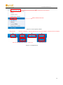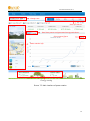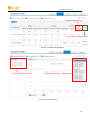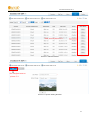
1
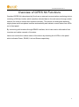
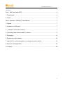
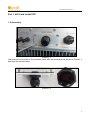
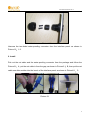
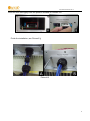
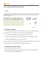
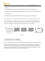
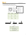
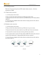
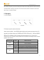
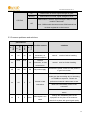
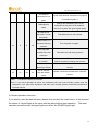
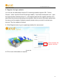
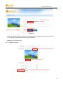
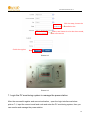
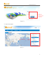
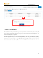
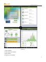
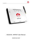
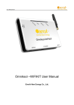
Omniksol GPRS Kit User Manual Omnik New Energy Co., Ltd. User manual version V2.3 Overview of GPRS Kit Functions Omniksol GPRS Kit is developed by Omnik as an external communication monitoring device, including a SIM card inside, which transfers collected data to the web server through mobile network for users to monitor their systems remotely. The device can distinguish between single-phase and three-phase inverters automatically and indicate current status from LEDs on its front panel. By connecting with inverters through RS485 interface, the kit can receive information from inverters and realize cascade of inverters. Users can monitor the runtime status of the device by checking the 4 LEDs on the panel which indicates Power, RS485, Link and Status respectively. 2 User manual version V2.3 catalog Part 1. 485 Card Install SOP ................................................................................................ 4 1. Disassembly ..................................................................................................................... 4 2. Install ................................................................................................................................ 5 Part 2. Omniksol –GPRS KIT User Manual .......................................................................... 7 1. Unpack ............................................................................................................................. 7 2. Installation of SIM card ..................................................................................................... 7 3.Installation of the data collector ....................................................................................... 7 4. Connecting data collector and PV inverter ........................................................................ 9 5. Debugging .......................................................................................................................11 6. Register the login website................................................................................................14 7. Login the PV monitoring system to manage the power station ........................................16 8. IPhone & iPad application................................................................................................22 9. Contacts ..........................................................................................................................24 3 User manual version V2.3 Part 1. 485 Card Install SOP 1. Disassembly Picture 1-1 Unscrew the four screws on the interface panel with the screwdriver as shown in Picture1-1 and keep the screws aside. Picture 1-2 4 User manual version V2.3 Picture1-3 Unscrew the two-holed water-proofing connector from the interface panel. as shown in Picture1-2 1-3. 2. Install Pick out the net cable and the water-proofing connector from the package and follow the Picture2-1 A , put the net cable in from the gap, as shown in Picture2-1 B, then put the net cable one after another into the kneck of the interface panel. as shown in Picture2-1 C. Picture 2-1 5 User manual version V2.3 Insert the 485 card lightly from the position showed in Picture2-2:A Picture 2-2 Finish the installation ,see Picture2-3 Picture2-3 6 User manual version V2.3 Part 2. Omniksol –GPRS KIT User Manual 1. Unpack After unpacking the box, please check the parts according to the below list. Contact the manufacturer immediately, should you find any damage, missing or wrong model of the device or any parts. SN Name Qty Model (pcs) A PV data collector 1 GPRSKIT B Power adapter 1 FY0502000 C screw 2 -- D Plastic expansion pipe 2 -- E Quick start guide 1 Picture1 2. Installation of SIM card 2.1 If the SIM card is the original card from manufacturer, you can use it directly without any more operation. 2.2 you are advised to use a manufacturer original SIM card If you use a SIM card bought by yourself . there would be two cases 1. If SIM card enables PIN code please disable PIN code before installation or usage. 2. If SIM card disables PIN code it can be used directly. Note The SIM card produced by the manufacturer is paired with the machine, so it can only be used together with the Data collector provided by the manufacturer. 3.Installation of the data collector 3.1 Wall-mounted data collector installation 1. Make a drill hole mark at the chosen installation place, the drill hole mark should be 2 horizontal holes with center distance 69mm; 7 User manual version V2.3 2. Make 2 holes φ6mm with a drill at the mark place, the hole depth should be not less than 30mm 3. Knock the plastic expansion pipe with a rubber hammer into the hole of the wall; 4. Screw 2 screws into the plastic expansion pipe, about 6mm of the screw head should be stretched out; 5. Mount the PV data collector GPRSKIT on the 2 screws in the wall(Picture 2). Note:The protection level of the PV data collector GPRS KIT is IP21. It cannot be installed outside or in the humid, dusty place, or some place with corrosive steam. It also should avoid the sunshine. What’s more, as metal construction would have shielding effect on wireless signal, the data collector antenna should be far away from the other metal construction for at least 10m from all directions. Picture2 3.2 Horizontal data collector installation Put the data collector on a fixed flat surface. Note:The protection level of the PV data collector GPRS KIT is IP21. It cannot be installed outside or in the humid, dusty place, or some place with corrosive steam. It also should avoid the sunshine, quake and pressure. What’s more, as metal construction would have shielding effect on wireless signal, the data collector antenna should be far away from the other metal construction for at least 10m from all directions. 8 User manual version V2.3 4. Connecting data collector and PV inverter 4.1 Data collector interface and connecting wire interface Line sequence of T568B 1. orange with white 2. orange 3. green with white RJ45 crystal head 4. blue 5. blue white white 6. green Picture 3 7. brown with white 8. brown Pin NO. RS485 RS422 1 NC NC 2 NC NC 3 NC RX+ 4 A TX+ 5 B TX- 6 NC RX- 7 GND GND 8 GND GND Picture 4 No. Function A Serial No. B RS485/422 interface C Power adapter interface D Antenna interface SIM card interface 9 User manual version V2.3 4.2 Connecting procedure Both ends of the connecting wire are RJ45 network cable connector,all the line sequence are T568B. 4.2.1 Single inverter connection 1. cut off the power of the inverter; 2. Plug one end of the network cable into any RJ45 port of the inverter; 3. Plug the other end of the network cable into the RS485/422 port of PV data collector GPRS KIT. 4. Connect the power adapter with the data collector and plug into the outlet, and turn the inverter switch on. 4.2.2 Multiple inverter connection 1. cut off the power of the inverter; 2. Plug one end of the network cable into any RJ45 port of any one inverter; 3. Plug the other end of the network cable into any RJ45 port of the second inverter; 4. Cascade all the inverters that need monitoring with the same method; 5. Use a network cable to connect PV data collector GPRS KIT with the first or the end inverter of the inverter serial,making up the series LAN, as in picture 5; 6. Connect the power adapter with the data collector and plug into the outlet, and turn the inverter switch on. Picture 5 10 User manual version V2.3 Note:Before connection, you must cut off the power of the inverter. Please make sure all the connections are finished before switching on the power in the inverter and data collector. Otherwise it would cause person injury or equipment damage. 5. Debugging 5.1 LED indicators Picture 6 5.2 Normal connection status instructions Under normal condition,after GPRS Kit data collector and inverter are powered on for 30 seconds, four indicator status are: POWER and STATUS: LEDs are On;LINK and 485/422: LEDs are On or blinking. If after the system has been powered on for 1 minute, the 4 indicators are not in the above status, please solve the problem according to below common problems and solutions. Indicator name POWER 485\422 LINK status Status instruction On Power is normal Off Power is abnormal On Data collector connects well with inverter. blinking Data collector is in data transmission with inverter. Off Data collector is not correctly connected with inverter. On Data collector connects well with the server. blinking Data collector is in data transmission with the server Off Data collector is not correctly connected with the server. 11 User manual version V2.3 On GSM module is normal, signal strength is good. blinking GSM module is normal, signal strength is so so. GSM module is normal, signal strength is bad; or GSM STATUS Off module is abnormal. Note:GSM module abnormal means GSM module has not been registered on the Internet. 5.3 Common problems and solutions phenomenon STATU S LINK 485/42 2 R POWE Possible reasons solutions Normal on on on on connection, no normal, need no further handling data transmission blink Normal blink on on connection, in data normal,need no further handling transmission off off off off No power supply Connect the power; make sure the power is in good connection. Check if the connecting wire is right,and make sure the connecting wire is according to T568B line sequence. Please use on off X X Inverter in bad professional network cable tester to test. connection Make sure the stability of the RJ-45 connector. Make sure the inverter is in normal working status. on X X blink GSM signal is too weak Change the installation place of the equipment or the place of the antenna, search for a place with good signal quality 12 User manual version V2.3 The antenna connection is not good. GSM signal is weak Check if the antenna connection is not good; If so please tighten it. Change the installation place of the equipment or the place of the antenna, search for a place with good signal quality No SIM card or SIM card is in bad Take SIM card out and reinstall. connection. GSM module is in on X X off abnormal working Turn the power on again; condition. If the SIM card enables PIN code Disenable the PIN code protection protection The SIM account Please check the SIM account, if the account is overdue. owes a fee please recharge the account. SIM card is a card Please contact the manufacturer customer abroad.(not China) service. Fail to connect on on off on with the remote server Please contact the manufacturer customer service. Note 1: X means the status is uncertain. Note 2: if you have operated as above, the equipment still can’t work normally, please reset the equipment. If you reset it the equipment still can’t work normally, please contact the manufacturer customer service. 5.4 Reset operation instruction If you want to reset the data collector, please click and hold the reset button, at this moment the status of 4 signal lights is the same with the status before reset operation. The reset operation successes until all signal lights are off but the POWER signal light. 13 User manual version V2.3 6. Register the login website You can use the web browser that the PV monitoring website supports: IE8,Firefox, Chrome,safari. Input the Omnik Portal login website:http://www.omnikportal.com/,open the login interface as below picture 6-1, click“register”and enter the register interface, fill in and submit the document according to the demand. After the user’s information upload onto the server and the register finishes successful, please enter your email to activate your account. Then the register is finished. 6.1 Click Register button to go to registering interface for new account Click and enter the register interface Picture 6-1 6.2 Fill in user’s information as required 14 User manual version V2.3 choose“Owner” Click and enter the configure interface Picture 6-2 Remarks: please read the <Omnik service agreement >carefully, the enclosure is the cost list for all the countries, please choose your operators Owner means the final user 6.2.1 “Owner” Account Click and choose the aim pic Click”OK”save the pic Fill in GPRS card’s S/N code, see pic 6-4 15 User manual version V2.3 Click the map, choose the installation site Select, and choose it to be the share mode, other user can see Finish the register Picture 6-3 Picture 6-4 7. Login the PV monitoring system to manage the power station After the successful register and account activation,open the login interface as below picture 7-1, input the correct email and code and enter the PV monitoring system, then you can monitor and manage the power station. 16 User manual version V2.3 Input the correct email and code Picture 7-1 7.1 “Owner” User Interface Power station list Picture 7-2 17 User manual version V2.3 Choose your aim station and enter Edit or delete the case Picture 7-3 List of power stations Not yet open Back to 7-2 interface Enter the sharing case Enter the configure “company account”interface Add one case under your account,same as 7-3 Reset password Picture 7-4 navigation bar 18 User manual version V2.3 Change case Case info search Real-time power and generated energy switchover Print current figure Power station info Energy saving Picture 7-5 Main interface of power station 19 User manual version V2.3 Internal temperature Latest data collecting time Picture 7-6 Real Time Interface Choose the aim inverter Parameter options Picture 7-7 History Interface 20 User manual version V2.3 Click ,turn to picture 7-7, Picture 7-8 Alert Interfaces The interface same as picture 7-3 Picture 7-9 System Setting Interface 21 User manual version V2.3 Picture 7-10 System Setting Interface 8. IPhone & iPad application After registration of the power station, you can input the key words: Omnik,solar, inverter, PV, energy ,plant, monitor at the app store, then you can download the Omnik solar (iPhone) and Omnik Solar HD(iPad) at app store. After the download input your user name and password, then visit your station,(we supply a free demo, for the users who do not register)choose the power station and enter the main interface, then you the daily energy etc. will be displayed. Meanwhile, you can view the relevant date to view the curve as below: 22 User manual version V2.3 Picture 8-1 1. Log in interface 2. Power station list interface 3. Main interface 4. Daytime curve interface 23 User manual version V2.3 9. Contacts If you have any technical problems about our products please contact us you should confirm the follow things before contact us: Device model Data collector serial number The number of connected inverter Omnik New Energy Co., Ltd. Add: Xinghu Road No.218 bioBAY Park C2, Suzhou China Zip code 215213 Fax: +86 512 6295 6682 Tel: +86 512 6295 6676 Mail: [email protected] 24