1
Digital Super Hybrid System
KX-TD816CE
KX-TD1232CE
Added and Changed Features for
Installation Manual and Programming Tables
Please read this manual first and then the Installation Manual.
In this manual, the last letter “CE” of each model number is omitted.
Warning
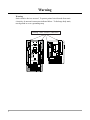
Warning:
Static sensitive devices are used. To protect printed circuit boards from static
electricity, do not touch connectors indicated below. To discharge body static,
touch ground or wear a grounding strap.
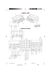
Warning : Static sensitive connectors
REMOTE
SYSTEM INTER
CONNECTION
DISA
DOORPHONE
2
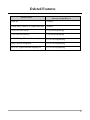
Table of Contents
Added Features
Section 1.4, Options
Pay Tone Card (KX-TD189) ...............................................................................................
2-ISDN S0 Line Unit (KX-TD280).....................................................................................
Section 2.4, Installation of Optional Cards and Units
2-ISDN S0 Line Unit Connection .......................................................................................
Installing Expansion Unit (KX-TD280)..............................................................................
Pay Tone Card (KX-TD189) Installation ............................................................................
Section 3, Features
Budget Management............................................................................................................
Calling Line Identification Restriction (CLIR) ...................................................................
Charge Fee Reference..........................................................................................................
CO Incoming Call Information Display..............................................................................
CO Incoming Call Information Log....................................................................................
Direct Dialing In (DDI).......................................................................................................
Emergency Call ...................................................................................................................
HOTEL APPLICATION .....................................................................................................
Check-In / Check-Out ......................................................................................................
Timed Reminder, Remote (Wake-Up Call) ......................................................................
SMDR for Timed Reminder ................................................................................................
Section 4, System Programming
[009] Emergency Dial Number Set ....................................................................................
[010] Budget Management.................................................................................................
[011] Charge Margin Rate ..................................................................................................
[120] Charge Display Selection..........................................................................................
[121] Assignment of Denomination ...................................................................................
[122] Charge Verification Assignment...............................................................................
[123] Charge Verification ID Code Set ..............................................................................
[124] Hotel Application......................................................................................................
[125] User Password ..........................................................................................................
[216] Message Waiting Ring Interval Time .......................................................................
[217] Timed Reminder Alarm Repeat Times .....................................................................
[218] Timed Reminder Alarm Interval Time .....................................................................
[417] CO Line Name Assignment......................................................................................
[418] ISDN Line Number Assignment ..............................................................................
[419] ISDN Outgoing CLIR Service Assignment..............................................................
[420] ISDN DDI Service Assignment................................................................................
[423] Pay-Tone Assignment ...............................................................................................
[610] ISDN DDI Number / Extension Number Transformation........................................
[611] ISDN DDI Number / Floating Number Transformation...........................................
6
6
6
7
9
12
12
13
14
15
16
17
18
18
19
20
21
22
23
24
25
26
27
28
29
30
31
32
33
34
35
36
37
38
39
3
Table of Contents
[815] SMDR Output Mode................................................................................................. 40
[990] System Additional Information, Fields (27) through (35)........................................ 41
Changed Features
Section 3, Features
Direct Inward System Access (DISA).................................................................................
Display, Call Information ....................................................................................................
Do Not Disturb (DND)........................................................................................................
DSS Console (KX-T7240 / KX-T7040)..............................................................................
Message Waiting .................................................................................................................
Operator...............................................................................................................................
Station Message Detail Recording (SMDR) .......................................................................
Section 4, System Programming
[001] System Speed Dialing Number Set...........................................................................
[002] System Speed Dialing Name Set ..............................................................................
[100] Flexible Numbering ..................................................................................................
[109] Expansion Unit Type ................................................................................................
[211] Dial Start Time..........................................................................................................
[412] Pause Time................................................................................................................
[413] Flash Time ................................................................................................................
[601] Class of Service ........................................................................................................
[990] System Additional Information, Fields (17) and (26) ..............................................
44
44, 46
44
44
44, 47
44
44, 48
44, 52
44, 54
44
45, 55
45
45
45
45, 57
45
Deleted Features
Section 3, Features
Caller ID ..............................................................................................................................
Calling Party Control (CPC) Signal Detection....................................................................
Section 4, System Programming
[110] Caller ID Code Set ....................................................................................................
[111] Caller ID Name Set ...................................................................................................
[405] CPC Signal Detection Incoming Set.........................................................................
[406] Caller ID Assignment ...............................................................................................
[415] CPC Signal Detection Outgoing Set .........................................................................
59
59
59
59
59
59
59
Programming Tables ........................................................................... 60
4
Added Features
5
1.4
Options
Pay Tone Card (KX-TD189)
Supports the Pay Tone service of the central office. While having
a conversation with an outside party, your central office generates
the pay tone so that the counting for fee starts for the call.
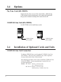
2-ISDN S0 Line Unit (KX-TD280)
One KX-TD280 can be installed per system.
D1232
DIGITAL SUPER HYBRID SYSTEM
D816
DIGITAL SUPER HYBRID SYSTEM
Panasonic
Panasonic
2 ISDN S0 lines
can be added.
2.4
2 ISDN S0 lines
can be added.
Installation of Optional Cards and Units
2-ISDN S0 Line Unit Connection
To add two ISDN S0 lines, use the optional 2-ISDN S0 Line Unit
(KX-TD280). This unit can be installed in any of the expansion
areas provided on the front of the main unit.
The following procedures can be used to install the 2-ISDN S0 Line
Unit (KX-TD280). System programming is required for unit
location identification.
Default KX-TD816: bottom = 4-CO Line Unit,
top = 8-Station Line Unit
KX-TD1232: bottom = 4-CO Line Unit,
middle and top = 8-Station Line Unit
6
Installing Expansion Unit (KX-TD280)
1. Loosen two screws on the cover plate.
Insert fingers into the slits to remove the
cover plate.
4. Loosen the outside screw and slide the
cover to the right.
D1232
DIGITAL SUPER HYBRID SYSTEM
D1232
DIGITAL SUPER
HYBRID SYSTE
M
Slit
Panasonic
Slit
Outside screw
Panaso
nic
Note Any of the cover plates can be
removed, as needed.
2. Connect the cabinet cord to the
connector in the main unit firmly.
5. Secure the inside screw (included) to fix
the cabinet to the main unit.
D1232
DIGITAL SUPER HYBRID SYSTEM
D1232
DIGITAL SUPER HYBRID SYSTEM
Inside screw
Panasonic
Panasonic
3. Hook the cabinet to the main unit and
slide the cabinet to the left until it is
secured.
D1232
DEGITAL SUPER HYBRID SYSTEM
Note Be sure to fix the inside screw to the
main unit, or the unit may not work
properly.
6. Prepare the required plugs. Two 4-pin
plugs are included in KX-TD280 to
connect four CO lines.
TB
TA
RA
RB
Panasonic
7
Installing Expansion Unit (KX-TD280)
7. Insert the plug into a jack on the unit.
Connect an earth wire to the earth terminal
on the extension expansion unit.
11. Fix the cords to the wall as shown so
that the front cover can be opened.
D1232
DIGITAL SUPER HYBRID SYSTEM
TB
TA
2C
O
w
/P
FT
2C
RA
RB
ISDN
Port No.1
O
ISDN
Port No.2
P
an
Panasonic
as
on
ic
To Terminal Board or Modular
Jacks from the Central Office
8. Tie all of the cords into a bundle. If
other cords are exposed in the upper
cabinets, tie them also.
9. Close the cabinet cover and secure
the outside screw.
10. Cover the cords with the cord holder
(included).
Notes • The KX-TD1232 is illustrated as a
main unit.
• If two or three expansion units are
installed, cut the cabinet covers on the
lower cabinets to allow the cords from
the upper cabinet to go down through
the cabinet covers. To protect the
cords, smooth the cut edges.
Cut here
D1232
DIGITAL SUPER HYBRID SYSTEM
Programming References
Cord holder
Panasonic
8
Section 4, System Programming,
[109] Expansion Unit Type
Pay Tone Card (KX-TD189) Installation
(1) Installing to the Initial CO Line Card
1. Loosen eight screws to open the inside cover of the main unit.
Note
If any cards, units, or cords are installed in the main unit, remove
them beforehand.
2. Attach the Pay Tone Card(s) (KX-TD189) to the CO Line Card,
with the spacers (Accessary included).
One Pay Tone Card for KX-TD816, and up to two Pay Tone Cards
for KX-TD1232 can be installed to the initial CO Line Card.
KX-TD816
CO Line
Card
Pay Tone Card
J200
Cut here
CO3,4
CO Line Card
JPB
OP
JPA
OP
Inside cover
OP
JPC
OP
JPD
J200
CO1,2
OPJPA - D
9
Pay Tone Card (KX-TD189) Installation
KX-TD1232
CO Line Card
B
Pay Tone Card
J200
A
Cut here
OP
JP
G
OP
JPH
J200
OP
JPC
OP
OPJPA ~ H
OP
JPB
CO3,4
CO1,2
OP
JPA
Inside cover
CO Line Card
CO5,6
JPD
OP
JPE
OP
JP
F
CO7,8
3. Put the inside cover back on the main unit and secure the screws.
4. If you do not cut the wire of the J200 in pay-tone card, the detected
mode is 16 KHz. If you cut the wire of the J200 in Pay Tone Card
(Open Mode), the detected mode is 12 KHz.
5. After installing the Pay Tone Card, if you hear a noise of the paytone signal, cut the option Jumper Wires, OPJPA through OPJPH
corresponds to CO1 through CO8 in the CO Card.
(OPJPA corresponds to CO1, OPJPB to CO2, OPJPC to CO3, OPJPD to CO4,
OPJPE to CO5, OPJPF to CO6, OPJPG to CO7, and OPJPH to CO8.)
— When you install the Pay Tone Card A, you will detect the pay-tone signal from
CO1 - CO4, and cut the corresponding option Jumper Wires, if needed.
— When you install the Pay Tone Card B, you will detect the pay-tone signal from
CO5 - CO8, and cut the corresponding option Jumper Wires, if needed.
10
Pay Tone Card (KX-TD189) Installation
(2) Installing to the Optional 4-CO Line Unit
The following procedures must be done before installing the 4-CO
Line Unit (KX-TD180) to the main unit.
1.
2.
3.
4.
Loosen five screws located on the rear of the 4-CO Line Unit.
Remove the back plate and take out the P-board.
Attach the Pay Tone Card to the P-board, fitting the connectors.
Put the P-board back into the cabinet and fix the rear plate with
the five screws.
5. If you do not cut the wire of the J200 in Pay Tone Card, the
detected mode is 16 KHz. If you cut the wire of the J200 in paytone card (Open Mode), the detected mode is 12 KHz.
back plate
J200
P-board
4C
O
@DI
GI
TA
L
SU
PE
R
HY
BR
ID
SY
ST
EM
J200
Note
Cut here
To install the 4-CO Line Unit to the main unit, refer to Section 2.4.4
“Installing Expansion Unit (KX-TD170 / KX-TD180)” in the
Installation Manual.
Programming References
Section 4, System Programming,
[423] Pay-Tone Assignment
Feature References
Section 3, Features,
Display, Call Information (in this manual)
HOTEL APPLICATION (in this manual)
11
BC
3
Features
Budget Management
Description
Limits the telephone usage to a pre-assigned amount. For
example, the limit may be the amount deposited at check-in of a
hotel. If the pre-assigned limit is reached, the extension user
cannot make further calls until he/she receives authorization from
the operator.
Conditions
None
Programming References
Section 4, System Programming,
[010] Budget Management
Feature References
Section 3, Features,
HOTEL APPLICATION
Operation References
Not applicable.
Calling Line Identification Restriction (CLIR)
Description
Allows the extension user to restrict the presentation of the calling
party’s number to the called party when making a call. This is one
of the ISDN services.
Conditions
If the presentation is enabled, the called party can check the calling
party’s number before the called party is answered it (Calling Line
Identification Presentation, CLIP).
Programming References
Section 4, System Programming,
[418] ISDN Line Number Assignment
[419] ISDN Outgoing CLIR Service Assignment
12
Feature References
None
Operation References
Not applicable.
3
Features
C
Charge Fee Reference
Description
Allows the pre-assigned display telephone user to view, clear
charges and print out the data by SMDR. Charges are displayed
per extension, CO line, account code, or the total of each can be
referred to.
Conditions
• The allowed extension is determined by System Programming.
• The verification ID is required to perform this feature.
• A maximum of 99999 Meter can be collected. The existing call is not
referred.
• It is programmable to select the first display, Meter or Charge by
System Programming. This can be switched manually at each
extension.
• Exchange rate between Meter or Charge is assigned by Station
Programming.
Programming References
Section 4, System Programming,
[120] Charge Display Selection
[122] Charge Verification Assignment
[123] Charge Verification ID Code Set
Station Programming.......................................................User Manual,
Charge Fee Reference
Feature References
None
Operation References
—User Manual
Station Programming,
Charge Fee Reference
13
C
3
Features
CO Incoming Call Information Display
Description
Provides the display proprietary telephone user with a preset CO
line name if an incoming outside call is received. If the CO name is
not assigned and the CO line is an ISDN line provided with CLIP
(Calling Line Identification Presentation) feature, shows the
caller’s telephone number and name on the display.
Conditions
• It is required to name CO lines by system programming.
• With the CLIP feature, the ISDN line informs the system of the caller’s
telephone number only. To display the name, the system compares the
informed number with the System Speed Dialling Numbers stored in
program [001] and if a match is found, decides the caller’s name by
using the System Speed Dialing Names stored in program [002].
• The CO line name display has precedence on the Operator’s telephone.
• The display DPT (KX-T7230 or KX-T7235) user can record the
information of the call received by CLIP feature (CO Incoming Call
Information Log feature).
Connection References
Section 2, Installation,
2.4 Installation of Optional Cards and Units (in this manual)
Programming References
Section 4, System Programming,
[001] System Speed Dialing Number Set
[002] System Speed Dialing Name Set
[417] CO Line Name Assignment
[418] ISDN Line Number Assignment
[419] ISDN Outgoing CLIR Service Assignment
14
Feature References
Section 3, Features,
CO Incoming Call Information Log
Operation Reference
—User Manual
DPT Features,
CO Incoming Call Information Display
3
Features
C
CO Incoming Call Information Log
Description
If the display digital proprietary telephone (KX-T7230 or KXT7235) user cannot answer a call, the telephone automatically
records the caller’s telephone number, name and the time. The user
can call back the caller by checking the call log. This is available if
such a telephone receives incoming outside calls from the ISDN
line provided with the CLIP (Calling Line Identification
Presentation) feature. A maximum of 15 calls per telephone can
be logged.
Conditions
• The call log is registered at the time DPT finishes ringing. If a call is
directed to multiple DPTs, the call log is registered at the DPT that has
the smallest jack number of the ringing DPTs.
• Transferred call information is also recorded.
• If the DPT is in Call Forwarding – No Answer or IRNA is activated,
the call log is registered at the original DPT but not at the destination
DPT unless the destination party answers the call and record it
manually.
• When the information area is full (i.e. more than 15 calls), the user can
control the log mode at his / her extension (CO Incoming Call
Information Log Mode). If the user sets this mode, new CO incoming
call information is retained but old data is discarded. If the user cancels
this mode, new CO incoming call information is not entered in the unit.
To set or cancel the mode, a corresponding feature number is used.
• The telephone user can lock the display of the unit so that CO
incoming call information is not shown on the display. A lock code is
required to set or cancel this feature. Operator can cancel the lock in
case the user forgets the lock code.
Connection References
Section 2, Installation,
2.4 Installation of Optional Cards and Units (in this manual)
Programming References
Section 4, System Programming,
[001] System Speed Dialing Number Set
[002] System Speed Dialing Name Set
[100] Flexible Numbering, CO incoming call information log mode/CO
incoming call information log lock
[417] CO Line Name Assignment
[418] ISDN Line Number Assignment
[419] ISDN Outgoing CLIR Service Assignment
15
D
3
Features
Feature References
Section 3, Features,
CO Incoming Call Information Display
Operation Reference
—User Manual
DPT Features,
CO Incoming Call Information Log Lock
CO Incoming Call Information Log Mode
Operator Service Features,
CO Incoming Call Information Log Lock Clear
Direct Dialing In (DDI)
Description
Provides an automatic direction of an incoming ISDN S0 line call
to a specific extension. This requires a DDI number informed
from the ISDN network. The DDI number is converted to a
specific extension number by using a pre-programmed conversion
table.
DSHS
Network
ISDN
External
telephone
555-4112
{
Extension
200
(DDI: 111)
201
(DDI: 112)
202
(DDI: 113)
DDI number
Explanation
1. An incoming call from the ISDN network reaches your DSHS
(Digital Super Hybrid System).
The ISDN network informs DSHS of the DDI number.
2. DSHS converts the DDI number to an extension number and
directs the call to the extension.
Conditions
• The DDI service can be enabled or disabled on a CO line basis.
• After the extension number is determined, the system operates the call
in the same way as the DIL 1:1 operation.
• If a DDI number cannot be converted to an extension number, the call
is put to IRNA destination.
Connection References
Section 2, Installation,
2.4 Installation of Optional Cards and Units (in this manual)
16
3
E
Features
Programming References
Section 4, System Programming,
[420] ISDN DDI Service Assignment
[610] ISDN DDI Number / Extension Number Transformation
[990] System Additional Information, Fields (31) and (32)
Feature References
None
Operation References
Not applicable.
Emergency Call
Description
Allows the extension user to dial out a pre-assigned emergency
number without seizing a CO line.
Conditions
• Emergency numbers are allowed even in the following cases:
• in Account Code – Verified mode
• in any toll restriction level
• after the pre-assigned charge limit is reached
• in Electronic Station Lockout
• A maximum of eight emergency numbers are assignable. An extension
number can be stored as an emergency number to call service desk
with 1 digit for HOTEL APPLICATION.
• [009] Emergency Dial Number Set — Emergency dial location number
(1-8) corresponds to [100] Flexible Numbering — No. 55-62.
<Example>
If you want to assign “110” as an emergency call, you need assign the
following programming:
— Assign [100] Flexible Numbering, Feature Number “55,”
Emergency call 1:110
— Assign [009] Emergency Dial Number Set, Location Number “1,”
1:9110
Programming References
Section 4, System Programming,
[009] Emergency Dial Number Set
[100] Flexible Numbering, Emergency call 1 through 8
Feature References
None
Operation References
—User Manual
DPT Features, SLT Features;
Emergency Call
17
H
3
Features
HOTEL APPLICATION
Description
Allows the operator to handle the front/operator services such as
check-in / check-out, timed reminder (wake-up call). This operation
is applicable to only the operator extension with a KX-T7235.
Check-In / Check-Out
Description
Allows the operator to operate the check-in / check-out service.
This feature can control the usage of an outside call by switching
the Class of Service between primary and secondary, and count
and print out the telephone charge and the other charges (such as
mini-bar charges).
Conditions
• Hotel application must be enabled by System Programming.
• When the check-in is assigned, the Class of Service is set to the
primary one and the charge counter will be cleared. When the checkout is assigned, the Class of Service is set to secondary one and the
total telephone charge and the other charge will be displayed and
printed out.
• There are two types of check-out mode, ready or not ready (cleaned up
or not). The check-out operation by the operator changes the room
status from check-in to check-out (not ready) mode. Changing from
check-out (not ready) to check-out (ready) mode can be executed either
from the room or by the operator.
• The telephone charge can be added to the surcharge according to the
pre-assigned margin rate.
• When Hotel Application is enabled, all extension is set to the primary
COS. After completing a confirmation of check-in and check-out, the
extension is set to the secondary COS.
• If the operator uses the paired DSS console, the operator can refer to
the room status on the DSS console while the display of paired KXTD7235 is in HOTEL menu. The lightening patterns of DSS button
and room status are shown below:
Lighting Pattern
Red on
Red flash
Off
Room Status
Check-in
Check-out (not ready)
Check-out (ready)
• It is possible to give a header to the printed bill such as the hotel’s
name or greeting or to assign the starting location of output data with a
personal computer.
• A new page is started for each print-out.
• It is possible to limit telephone usage to a pre-assigned amount by
System Programming.
18
3
H
Features
Programming References
Section 4, System Programming,
[010] Budget Management
[011] Charge Margin Rate
[100] Flexible Numbering, Check-out ready
[124] Hotel Application
[423] Pay-Tone Assignment
[601] Class of Service
Feature References
Operation References
—User Manual
Section 3, Features,
Budget Management
Charge Fee Reference
Operator Service Features,
Hotel Application
Timed Reminder, Remote (Wake-Up Call)
Description
Allows the operator to remotely set, cancel and confirm the wakeup call for an extension.
Conditions
• When either an operator or the extension sets a new time, the pre-set
time is cleared.
• The Alert button on Operator 1’s extension turns red if the guest does
not respond to the alarm ringing. The Alert button can also be used to
confirm the not responded room number or to call back the room.
• The Alert button can be assigned to a flexible CO button on Operator
1’s extension only.
• SMDR records the detailed Timed Reminder information and prints it
out automatically when the Timed Reminder starts and it is not
answered. You can disable the printout by System Programming.
Programming References
Section 4, System Programming,
[100] Flexible Numbering, Timed reminder, remote
[217] Timed Reminder Alarm Repeat Times
[218] Timed Reminder Alarm Interval Time
[990] System Additional Information, Field (36)
Feature References
Section 3, Features,
SMDR for Timed Reminder
Operation References
—User Manual
Operator Service Features,
Hotel Application
19
S
3
Features
SMDR for Timed Reminder
Description
Station Message Detail Recording (SMDR) automatically records
detailed Timed Reminder information. It is printed out when the
Timed Reminder starts and the alarm is not answered. To enable
the printout, refer to the program [990] “System Additional
Information, Field (36),” which allows you to print out the
following records:
• Date
• Time
• Extension number
• Start / No Answer
An example of a printed Timed Reminder record:
Date
Time
06/24/96 10:03AM
06/24/96 10:04AM
Ext CO
Dial Number
103
103
Reminder / Start
Reminder / No Answer
Conditions
Duration
CD
Connect a printer provided with an EIA (RS-232C) interface to the EIA
(RS-232C) connector located on the main unit.
Connection References
Section 2, Installation,
2.3.10 Printer Connection
Programming References
Section 4, System Programming,
[801] SMDR Format
[806]–[807] EIA (RS-232C) Parameters
[990] System Additional Information, Field (36)
20
Acc code
Feature References
Section 3, Features,
Station Message Detail Recording (SMDR)
Timed Reminder
Timed Reminder, Remote (Wake-Up Call)
Operation References
Not applicable.
4.2
Manager Programming
009
Emergency Dial Number Set
Description
Assigns emergency call numbers.
Selection
• Emergency dial location number: 1 through 8
• Telephone number: 16 digits (max.)
Default
All locations – Not stored
Programming
1.
Enter 009.
Display:Emergency Call
2.
Press NEXT.
Display:Emergency NO?→
3.
Enter an emergency dial location number.
To enter emergency number 1, you can also press NEXT.
Display example: 1:9110
4.
Enter a telephone number.
To delete the current entry, press CLEAR.
To change the current entry, press CLEAR and the new number.
5.
Press STORE.
6.
To program another emergency dial number, press NEXT or
PREV, or SELECT and the desired emergency dial
location number.
7.
Repeat steps 4 through 6.
8.
Press END.
Conditions
• There is a maximum of eight emergency call numbers. Each number
has a maximum of 16 digits, consisting of 0 through 9, , #, F (Flash),
P (Pause) and – (hyphen).
• No restriction is applied to emergency call numbers.
• For outside calls, enter a line access code (9, 81 through 88) before the
phone number.
• Emergency dial location number (1-8) corresponds to [100] Flexible
Numbering — No. 55-62.
Feature References
Section 3, Features,
Emergency Call
21
010
4.2
Manager Programming
Budget Management
Description
Assigns the charge limitation of a call on an extension basis.
Selection
• Jack number: KX-TD816 – 01 through 16, (-1 / -2),
KX-TD1232 – 01 through 64, (-1 / -2),
( =all jacks, -1 = first part, -2 = second part)
• Charge limitation : 0 through 59999
Default
All jacks – 0
Programming
1.
Enter 010.
Display:Charge Limit
2.
Press NEXT.
Display:Jack NO?→
3.
Enter a jack number.
To enter jack number 01, you can also press NEXT.
Display example: #01–1: 0
4.
Enter a charge limitation.
To delete the charge limitation, press CLEAR.
22
5.
Press STORE.
6.
To program another jack, press NEXT or PREV, or
SELECT and the desired jack number.
7.
Press END.
Conditions
• If the charge limitation is set to “0,” no restriction is applied.
• To assign all jack number to one selection, press the
key in step 3.
In this case, the display shows the contents programmed for Jack 01.
Feature References
Section 3, Features,
Budget Management
4.2
Manager Programming
011
Charge Margin Rate
Description
Assigns the margin rate of a telephone charge.
Selection
Margin (%): 0 through 999
Default
0%
Programming
1.
Enter 011.
Display: Charge Margin
2.
Press NEXT.
Display: Margin: 0%
3.
Enter a charge margin rate.
To delete the charge limitation, press CLEAR.
Conditions
4.
Press STORE.
5.
Press END.
Telephone charge = Real charge x (
100 + rate
)
100
The telephone charge will be printed out when checking out.
Feature References
Section 3, Features,
HOTEL APPLICATION – Check-In / Check-Out
23
4.3
120
System Programming
Charge Display Selection
Description
Assigns the initial display format of charge fee on a display
telephone.
Selection
in Meter / in Charge
Default
in Meter
Programming
1.
Enter 120.
Display: Charge Meter
2.
Press NEXT.
Display example: in Meter
3.
Keep pressing SELECT until the desired selection is
displayed.
4.
Press STORE.
5.
Press END.
Conditions
• This programming is only effective when you select for charge (SMDR
Output) by Program [815] “SMDR Output Mode.”
• This programming will also determine the print-out format of the
charge fee reference.
Feature References
24
Section 3, Features,
Charge Fee Reference
Display, Call Information
Station Message Detail Recording (SMDR)
4.3
System Programming
121
Assignment of Denomination
Description
Assigns the Denomination required for your country.
Selection
2 characters (Max.)
Default
none
Programming
1.
Enter 121.
Display: Denomination
2.
Press NEXT.
Display example: Denomi.: KC
3.
Enter a 0-9,
, #, SELECT, CLEAR,
or none.
To change the current entry, press CLEAR and the new characters.
To enter characters, see Section 4.1.3 “Entering Characters.”
4.
Press STORE.
5.
Press END.
Conditions
• If more than two digits are entered, they are ignored.
Feature References
Section 3, Features,
Display, Call Information
25
4.3
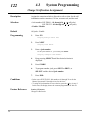
122
System Programming
Charge Verification Assignment
Description
Assigns the extension which is allowed to refer or clear for the call
information on the extension, CO line, account code, and the total.
Selection
• Jack number: KX-TD816 – 01 through 16, ( =all jacks)
KX-TD1232 – 01 through 64, ( =all jacks)
• Enable / Disable
Default
All jacks – Enable
Programming
1.
Enter 122.
Display:Charge Refer Ext
2.
Press NEXT.
Display:Jack NO?→
3.
Enter a jack number.
To enter jack number 01, you can also press NEXT.
Display example: #01:Enable
26
4.
Keep pressing SELECT until the desired selection is
displayed.
5.
Press STORE.
6.
To program another jack, press NEXT or PREV, or
SELECT and the desired jack number.
7.
Press END.
Conditions
• In the case of KX-TD1232, Jack numbers 01 through 32 are for the
Master System and 33 through 64 are for the slave.
• To assign all jack numbers to one selection, press the
key in step 3.
In this case, the display shows the contents programmed for Jack 01.
Feature Reference
Section 3, Features,
Charge Fee Reference
4.3
System Programming
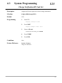
123
Charge Verification ID Code Set
Description
Assigns an ID code required to refer the charge information.
Selection
4 digits (0000 through 9999)
Default
1234
Programming
1.
Enter 123.
Display: Charge ID Code
2.
Press NEXT.
Display example: Code: 1234
3.
Enter an ID code.
To delete the current entry, press CLEAR.
4.
Press STORE.
5.
Press END.
Conditions
None
Feature Reference
Section 3, Features,
Charge Fee Reference
27
4.3
124
System Programming
Hotel Application
Description
Assigns whether the hotel application is enabled or disabled.
Selection
Disable / Enable
Default
Disable
Programming
1.
Enter 124.
Display: Hotel Apply Asn
2.
Press NEXT.
Display example: Hotel : Disable
28
3.
Keep pressing SELECT until the desired selection is
displayed.
4.
Press STORE.
5.
Press END.
Conditions
If “Enable” is selected, the menu “Hotel” is displayed on the operator
extension’s KX-T7235 and the “Check–In / Check–Out” feature is
available.
Feature Reference
Section 3, Features,
HOTEL APPLICATION
4.3
System Programming
125
User Password
Description
Assigns the password required for entering the User Programming
mode.
In the User Programming Mode, any display proprietary telephone
user in the system can set the following programs:
[000] Date and Time Set
[001] System Speed Dialing Number Set
[002] System Speed Dialing Name Set
[003] Extension Number Set
[004] Extension Name Set
[005] Flexible CO Button Assignment
[006] Operator / Manager Extension Assignment
[007] DSS Console Port and Paired Telephone Assignment
[008] Absent Messages
[009] Emergency Dial Number Set
[010] Budget Management
[011] Charge Margin Rate
Selection
Password: 4 through 7 digits
Default
1234
Programming
1.
Enter 125.
Display: User Password
2.
Press NEXT.
Display example: Password:1234
3.
Enter a password.
To change the current entry, press CLEAR and enter the new
password.
4.
Press STORE.
5.
Press END.
Conditions
• The password can be from four to seven digits long. Valid numbers are
from 0 to 9.
• If less than four digits are entered, they will not be stored.
• You cannot leave the entry empty.
Feature Reference
––User Manual
Section 3, Features,
User Programming Mode
29
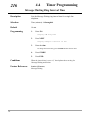
4.4
216
Timer Programming
Message Waiting Ring Interval Time
Description
Sets the Message Waiting ring interval time for a single line
telephone.
Selection
Time (minutes) : 0 through 64
Default
10 min
Programming
1.
Enter 216.
Display: MW Ring Time
2.
Press NEXT.
Display example: Interval: 10 min
3.
Enter the time.
To change the current entry, press CLEAR and enter the new time.
30
4.
Press STORE.
5.
Press END.
Conditions
When the interval time is set to “0,” the telephone does not ring for
Message Waiting notification.
Feature References
Section 3, Features,
Message Waiting
4.4
Timer Programming
217
Timed Reminder Alarm Repeat Times
Description
Sets the number of times Timed Reminder alarm is tried.
Selection
Number of times : 1 through 5
Default
3 times
Programming
1.
Enter 217.
Display: Alarm Times
2.
Press NEXT.
Display example: Attempt:3
3.
Enter the time.
To change the current entry, press CLEAR and enter the new time.
4.
Press STORE.
5.
Press END.
Conditions
One attempt is equivalent to 30 seconds.
Feature References
Section 3, Features,
Timed Reminder
31
4.4
218
Timer Programming
Timed Reminder Alarm Interval Time
Description
Sets the Timed Reminder alarm interval time.
Selection
Time (seconds) : 30 through 240
Default
60 sec
Programming
1.
Enter 218.
Display: Alarm Interval
2.
Press NEXT.
Display example: Interval: 60 sec
3.
Enter the time.
To change the current entry, press CLEAR and enter the new time.
32
4.
Press STORE.
5.
Press END.
Conditions
None
Feature References
Section 3, Features,
Timed Reminder
4.6
CO Line Programming
417
CO Line Name Assignment
Description
Used to name CO lines. The preset name is shown on a display
proprietary telephone when an incoming outside call is placed to
the telephone.
Selection
• CO line number:
KX-TD816 – 01 through 08, ( =all CO lines)
KX-TD1232 – 01 through 24, ( =all CO lines)
• Name: 10 characters (max.)
Default
All CO lines – Not stored
Programming
1.
Enter 417.
Display: CO Line Name
2.
Press NEXT.
Display: CO Line NO?→
3.
Enter a CO line number.
To enter CO line number 01, you can also press NEXT.
Display example: CO01:Not Stored
4.
Enter a name.
For entering characters, see Section 4.1.3 “Entering Characters.”
To delete the current entry, press CLEAR.
To change the current entry, press CLEAR and enter the new name.
5.
Press STORE.
6.
To program another CO line, press NEXT or PREV, or
SELECT and the desired CO line number.
7.
Repeat steps 4 through 6.
8.
Press END.
Conditions
• In the case of KX-TD1232, CO01 through CO12 are for the Master
System and CO13 through CO24 are for the Slave, if available.
• There is a maximum of 24 names. Each name has a maximum of 10
characters.
• To assign all CO lines to one selection, press the
key in step 3. In
this case, the display shows the contents programmed for CO01.
Feature References
Section 3, Features,
CO Incoming Call Information Display
Display, Call Information
33
4.6
418
CO Line Programming
ISDN Line Number Assignment
Description
Assigns your telephone number of the ISDN network line. Your
telephone number is informed to the called party with the CLIP
(Calling Line Identification Presentation) feature offered by the
ISDN network service.
Selection
• CO line number: KX-TD816 – 05 through 08
KX-TD1232 – 09 through 12, 21 through 24
• Telephone number: 16 digits (max.)
Default
All CO lines – Not stored
Programming
1.
Enter 418.
Display: ISDN CO NO.
2.
Press NEXT.
Display: CO Line NO?→
3.
Enter a CO line number.
To enter CO line number 05 for KX-TD816 or 09 for KX-TD1232,
you can also press NEXT.
Display example: CO09:Not Stored
4.
Enter the telephone number.
To delete the current entry, press CLEAR. To change the current
entry, press CLEAR and the new number.
34
5.
Press STORE.
6.
To program another CO line, press NEXT or PREV, or
SELECT and the desired CO line number.
7.
Repeat steps 4 through 6.
8.
Press END.
Conditions
• In the case of KX-TD1232, CO09 through CO12 are for the Master
System and CO21 through CO24 are for the Slave, if available.
• To display parts of the number which have scrolled off the display,
press
or
.
• Your telephone number is informed to the called party if outgoing CLIR
feature is disabled for the ISDN line by program [419] “ISDN Outgoing
CLIR Service Assignment.”
Feature References
Section 3, Features,
CO Incoming Call Information Display
CO Incoming Call Information Log
Direct Dialing In (DDI)
4.6
CO Line Programming
419
ISDN Outgoing CLIR Service Assignment
Description
Assigns whether ISDN CLIR (Calling Line Identification
Restriction) service is enabled or disabled for outgoing outside
calls. If disabled, the subscriber’s number of your system is
informed to the called party.
Selection
• CO line number:
KX-TD816 – 05 through 08, ( =all CO lines)
KX-TD1232 – 09 through 12, 21 through 24, ( =all CO lines)
• Enable / Disable
Default
All CO lines – Enable
Programming
1.
Enter 419.
Display: ISDN CLIR Send
2.
Press NEXT.
Display: CO Line NO?→
3.
Enter a CO line number.
To enter CO line number 05 for KX-TD816 or 09 for KX-TD1232,
you can also press NEXT.
Display example: CO09:Enable
4.
Keep pressing SELECT until the desired selection is
displayed.
5.
Press STORE.
6.
To program another CO line, press NEXT or PREV, or
SELECT and the desired CO line number.
7.
Repeat steps 4 through 6.
8.
Press END.
Conditions
• In the case of KX-TD1232, CO09 through CO12 are for the Master
System and CO21 through CO24 are for the Slave, if available.
• To assign all CO lines to one selection, press the
key in step 3. In
this case, the display shows the contents programmed for CO05 (for
KX-TD816) or CO09 (for KX-TD1232).
• Program [418] “ISDN Line Number Assignment” is used to store the
subscriber’s number of your system that is informed to the called party.
Feature References
Section 3, Features,
Calling Line Identification Restriction (CLIR)
CO Incoming Call Information Display
35
4.6
420
CO Line Programming
ISDN DDI Service Assignment
Description
Enables or disables ISDN DDI service per CO line.
Selection
• CO line number:
KX-TD816 – 05 through 08, ( =all CO lines)
KX-TD1232 – 09 through 12, 21 through 24, ( =all CO lines)
• Enable / Disable
Default
All CO lines – Disable
Programming
1.
Enter 420.
Display: ISDN DDI
2.
Press NEXT.
Display: CO Line NO?→
3.
Enter a CO line number.
To enter CO line number 05 for KX-TD816 or 09 for KX-TD1232,
you can also press NEXT.
Display example: CO09:Disable
36
4.
Keep pressing SELECT until the desired selection is
displayed.
5.
Press STORE.
6.
To program another CO line, press NEXT or PREV, or
SELECT and the desired CO line number.
7.
Repeat steps 4 through 6.
8.
Press END.
Conditions
• In the case of KX-TD1232, CO09 through CO12 are for the Master
System and CO21 through CO24 are for the Slave, if available.
• To assign all CO lines to one selection, press the
key in step 3. In
this case, the display shows the contents programmed for CO05 (for
KX-TD816) or CO09 (for KX-TD1232).
Feature References
Section 3, Features,
Direct Dialling In (DDI)
4.6
CO Line Programming
423
Pay-Tone Assignment
Description
Enables Pay-Tone for the CO lines.
Selection
• CO line number:
KX-TD816 – 01 through 08, ( =all CO lines)
KX-TD1232 – 01 through 24, ( =all CO lines)
• Enable / Disable
Default
All CO lines – Disable
Programming
1.
Enter 423.
Display: Pay-Tone Asn
2.
Press NEXT.
Display: CO Line NO?→
3.
Enter a CO line number.
To enter CO line number 01, you can also press NEXT.
Display example: CO01:Disable
4.
Keep pressing SELECT until the desired selection is
displayed.
5.
Press STORE.
6.
To program another CO line, press NEXT or PREV, or
SELECT and the desired CO line number.
7.
Repeat steps 4 through 6.
8.
Press END.
Conditions
• An optional Pay Tone Card (KX-TD189) must be installed on CO
board to receive the Pay-Tone.
• In the case of KX-TD1232, CO01 through CO12 are for the Master
System and CO13 through CO24 are for the Slave.
• To assign all CO lines to one selection, press the
key in step 3. In
this case, the display shows the contents programmed for CO01.
Feature References
Section 3, Features,
Display, Call Information
HOTEL APPLICATION
37
610
4.8
Extension Programming
ISDN DDI Number / Extension Number Transformation
Description
Used to convert a DDI number to an extension number in order to
put an incoming DDI call to a specific extension.
Selection
• Jack number: KX-TD816 – 01 through 16 (-1 / -2),
KX-TD1232 – 01 through 64 (-1 / -2),
(-1 = first part, -2 = second part)
• DDI Number: 1 through 6 digits
Default
All jacks – Not stored
Programming
1.
Enter 610.
Display: EXT. DDI NO.
2.
Press NEXT.
Display: Jack NO?→
3.
Enter a jack number.
To enter jack number 01, you can also press NEXT.
To select the second part (-2), press NEXT after entering a jack
number.
Display: #01-1:001
4.
Enter a DDI number.
To delete the current entry, press CLEAR.
38
5.
Press STORE.
6.
To program another jack, press NEXT or PREV, or
SELECT and the desired jack number.
7.
Repeat steps 4 through 6.
8.
Press END.
Conditions
• There is a maximum of 128 DDI numbers. Each DDI number can be
one through six digits, consisting of 0 through 9.
• In the case of KX-TD1232, jack numbers 01 through 32 are for the
Master System and 33 through 64 are for the Slave, if available.
• For an explanation of jack numbering, see “Rotation of jack number”
on page 4-7 of the Installation Manual.
Feature References
Section 3, Features,
Direct Dialing In (DDI)
4.8
Extension Programming
611
ISDN DDI Number / Floating Number Transformation
Description
Used to convert a DDI number to an floating number in order to
put an incoming DDI call to a specific floating station.
Selection
• Floating Station : KX-TD816 – Operator / Pager 1
KX-TD1232 – Operator / Pager 1 / Pager 2 /
Pager 3 / Pager 4 / DISA 1/
DISA 2 / MODEM
• DDI Number : 1 through 6 digits
Default
All floating stations – Not stored
Programming
1.
Enter 611.
Display: F.EXT. DDI NO.
2.
Press NEXT to program the operator.
Display: Operator:
3.
Enter a DDI number.
To delete the current entry, press CLEAR.
4.
Press STORE.
5.
To program another floating station, press NEXT or PREV
until and the desired floating station is displayed.
6.
Repeat steps 3 through 5.
7.
Press END.
Conditions
Each DDI number can be one through six digits, consisting of 0 through
9.
Feature References
Section 3, Features,
Direct Dialing In (DDI)
39
4.9
815
Resource Programming
SMDR Output Mode
Description
Assigns the SMDR Output Mode. There are two standards
available – Regular and Charge.
Selection
Regular / Charge
Default
Regular
Programming
1.
Enter 815.
Display: SMDR Output Mode
2.
Press NEXT.
Display example: SMDR:Regular
40
3.
Keep pressing SELECT until the desired selection is
displayed.
4.
Press STORE.
5.
Press END.
Conditions
• Select the Output Mode used by your SMDR.
• If you assign for Charge, you can select the display in Meter / in Charge
through Program [120] “Charge Display Selection.”
Feature References
Section 3, Features,
Station Message Detail Recording (SMDR)
4.10
Option Programming
990
System Additional Information
Description
Area 4
Field (27) is added to Area 4, (28) through (33) are added to Area 5
and (35) is added to Area 6.
KX-TD1232 – [17] through [24] below match CO lines 17 through 24:
Display
example
1111111000000000
↓ ↓ ↓ ↓ ↓ ↓ ↓ ↓
CO number
[24][23][22] [21][20][19][18][17]
↓
(unused)
Field number
↓ ↓
↓ ↓
(27)(unused)(25)(24)
↓
(23)
Area 5
Display
example
1111111011101011
Field number
↓
↓ ↓ ↓ ↓ ↓ ↓ ↓ ↓ ↓ ↓
unused
(36) (33)(32)(31) un- (34) un- (30)(29)(28)
used
used
Area 6
Display
example
1111111111111111
Field number
↓
↓
unused
(35)
Explanation for Area 4
Field
(27)
Description
Selection
Enables or disables the CO pulse
0 : disable
feedback tone when a dialed number is 1 : enable
sent to the line.
Default
References
1
None
41
4.10
990
Option Programming
System Additional Information (contd.)
Explanation for Area 5 and 6
Field
Description
(28)
(29)
(30)
(31)
ISDN Layer 1 active mode
ISDN Data Link mode
ISDN TEI mode
In the day mode, selects the
destination when the
incoming DDI number is a
floating number of the
operator.
In the night mode, selects
the destination when the
incoming DDI number is a
floating number of the
operator.
Assigns whether the new
page is ejected or not when
the Hotel Application is
printed out by SMDR.
Assigns the reference mode
whether the DDI call
number of ISDN shows the
whole number or one digit at
a time.
Sets the time after
terminating the OGM.
Enables or disables the
SMDR printout for Timed
Reminder when it starts and
it is not answered.
(32)
(33)
(34)
(35)
(36)
Selection
Default Reference
1
1
0
1
None
None
None
Direct Dial In
(DDI)
0 : DIL 1:N 1 : Operator
1
Direct Dial In
(DDI)
0 : Disable 1 : Enable
0
Hotel
Application
0 : whole number
1 : one digit at a time
0
Direct Dial In
(DDI)
0 : 0 sec.
1
DISA
OGM
SMDR for
Timed
Reminder
0 : By call
0 : By call
0 : Fix (0)
0 : DIL 1:N
1 : Permanent
1 : Permanent
1 : Automatic
1 : Operator
1 : 5 sec.
0 : Disable 1 : Enable
1
Selection
• Area code: 01 (area 1) / 02 (area 2) / 03 (area 3) / 04 (area 4) /
05 (area 5) / 06 (area 6) / 07 through 12 are reserved
• Field number : 01 through 36
• Selection: See “Selection” shown above and on pages 4-127
through 4-129 in the main Installation Manual.
Default
See “Default” shown above and on pages 4-127 through 4-129 in
the main Installation Manual.
For programming instruction, please refer to the program [990] “System Additional Information” in the
main Installation Manual.
42
Changed Features
43
FEATURE TITLE
SECTION OF
THE MANUAL
Direct Inward System
Access (DISA)
Section 3
REVISION
Disconnected
after 5 seconds.
This timer can be changed to 0 second by program
[990] “System Additional Information, Field (35).”
Display, Call
Information
Section 3
This feature has been replaced with a new one. For
details, refer to page 46.
Do Not Disturb (DND)
Section 3
Conditions
• DND also works for doorphone calls.
DSS Console (KXT7240 / KX-T7040)
Section 3
If a port connected to a DSS Console is programmed
as a XDP jack, a SLT can be connected to the port in
parallel.
Message Waiting
Section 3
This feature has been replaced with a new one. For
details, refer to page 47.
Operator
Section 3
Both operators (1 and 2) have the ability to perform all
operator service features.
Station Message Detail
Recording (SMDR)
Section 3
This feature has been replaced with a new one. For
details, refer to page 48.
[001] System Speed
Dialing Number Set
Section 4
These programs have been replaced with new ones.
For details, refer to pages 52 through 54.
[002] System Speed
Dialing Name Set
Section 4
[100]
Flexible Numbering
Section 4
Feature Number List — Additional numbers
Number
54
55-62
63
64
65
66
44
Feature
Default
Reserved
Emergency call 1 through 8
none
Timed reminder, remote
7
CO incoming call information log mode
56
CO incoming call information log lock
57
Check-out ready
736
FEATURE TITLE
SECTION OF
THE MANUAL
REVISION
[109]
Expansion Unit Type
Section 4
This program has been replaced with a new one.
For details, refer to page 55.
[211] Dial Start Time
Section 4
Default
500 ms
[412] Pause Time
Section 4
Default
All CO line groups — 4.5 sec
[413] Flash Time
Section 4
Default
All CO line groups — 96 ms
[601] Class of Service
Section 4
This program has been replaced with a new one. For
detail, refer to page 57.
[990] System
Additional Information
Section 4
Default
Field (17) — 0
Default
Field (26) — 0
45
D
3
Features
Display, Call Information
Description
A display-type proprietary telephone shows the user the following
call information:
Extension number and name
These are shown when calling or when called by an
extension user and during an established intercom call.
A display example: 123: Smith
Dialed telephone number
This is shown when dialing the telephone number.
A display example: 91234567890
Number or name of the caller
These are shown when receiving an incoming outside call
on ISDN network.
Display examples: 0712225555
JOHN WHITE
CO line number and name
This is shown when receiving an outside call.
A display example: CO03:AB COMPANY
Charge Meter
This is shown during an established call.
A display example: CO01:00005
Charge Fee
This is shown during an established call.
A display example: CO01:00001.15KC
Call duration
This is shown during an established outside call. The
display remains for five seconds after the call is finished.
A display example: CO 02 0:02'28
Conditions
• Extension numbers and names, and CO line names are programmable.
If no name is stored, only the number is displayed.
• The display shows no intercom call duration.
• The outgoing outside call duration starts when the programmable timer
expires.
• It is programmable to select the first display, meter or charge, by system
programming. To alternate the display, press the FWD/DND button.
Programming References
Section 4, System Programming,
[003] Extension Number Set
[004] Extension Name Set
[120] Charge Display Selection
46
3
Features
M
[121] Assignment of Denomination
[212] Call Duration Count Start Time
[417] CO Line Name Assignment
[423] Pay-Tone Assignment
Station Programming.......................................................User Manual
Charge Fee Reference – New Rate Set
Feature References
Section 3, Features,
Charge Fee Reference
Operation References
—User Manual
DPT Features,
Display Call Information
Message Waiting
Description
The system supports the ability to inform the called party of a
waiting message. The user, with a MESSAGE button, knows there
is a message if the LED of the MESSAGE button is lit red. Even if
the button is not provided nor assigned, the called party hears a
special dial tone, when he / she goes off-hook. Pressing the lit
MESSAGE button also means to call back the extension that left
the message or listen to the messages which are stored in the
mailbox of a Voice Processing System.
Conditions
• For a proprietary telephone which is not provided with a MESSAGE
button, a flexible CO button can be assigned as the MESSAGE button
either by System or Station Programming.
• Cancelling a message can be performed from the extension setting it or
from the extension receiving it.
• The system supports a maximum of 128 simultaneous messages.
• Messages are always left on the original extension. It is not sent to a
Call Forwarding or Station Hunting destination.
• A single line telephone or KX-T7052 user will hear the ring tone as a
notification, if he / she receives a message. It is programmable to set
the interval of a ring tone by System Programming.
Programming References
Section 4, System Programming,
[005] Flexible CO Button Assignment
[100] Flexible Numbering, Message
[216] Message Waiting Ring Interval Time
[990] System Additional Information, Field (9)
Station Programming.......................................................User Manual,
Flexible Button Assignment – Message Waiting (MESSAGE) Button
47
S
3
Feature References
Section 3, Features,
Dial Tone, Distinctive
Operation References
—User Manual
Features
Voice Mail Integration
DPT Features, SLT Features;
Message Waiting
Station Message Detail Recording (SMDR)
Description
Station Message Detail Recording (SMDR) automatically records
detailed call information for outside calls. A printer connected to
the EIA (RS-232C) port can be used to print incoming and
outgoing outside calls as well as print a hard copy of System
Programming. To print the call records, use the program [800]
“SMDR Incoming / Outgoing Call Log Printout,” which allows you
to print out the following records:
• Records of all outgoing outside calls or outgoing toll calls.
• Record of incoming outside calls.
There are three types of the call record, which are the regular call
record, the charge call record and the meter call record.
An example of a printed regular call record: When selected for the regular display by
Program [815] “SMDR Output Mode.”
48
Date
Time
Ext CO
Dial Number
Duration
Acc code
06/24/96
06/24/96
06/24/96
06/24/96
06/24/96
06/24/96
06/24/96
06/24/96
06/24/96
10:03AM
10:07AM
10:08AM
10:08AM
10:09AM
10:10AM
10:11AM
10:11AM
10:20AM
101
103
104
105
280
103
280
280
120
01
20
10
10
14
20
12
22
13
123456789012345678901234567890
<INCOMING>
<INCOMING>
<INCOMING>
10222P1-202-346-7890
<INCOMING>
<INCOMING>
0924312111
<INCOMING>
00:05'12
00:00'56
00:00'20
00:10'01
00:09'18
00:01'24
00:00'24
00:03'02
00:21'46
1234567890
•
•
•
(1)
•
•
•
(2)
•
•
•
(3)
•
•
•
(4)
•
•
•
(5)
•
•
•
(6)
431211
431211
001
CD
TR
FW
D1
RM
•
•
•
(7)
•
•
•
(8)
3
S
Features
An example of a printed charge call record: When selected for charge by Program
[815] “SMDR Output mode” and selected for charge display by program [120] “Charge
Display Selection.”
Date
Time
Ext CO
Dial Number
Duration
Cost
Acc code
06/24/96
06/24/96
06/24/96
06/24/96
06/24/96
06/24/96
06/24/96
06/24/96
06/24/96
10:03AM
10:07AM
10:08AM
10:08AM
10:09AM
10:10AM
10:11AM
10:11AM
10:20AM
101
103
104
105
280
103
280
280
120
01
20
10
10
14
20
12
22
13
12345678901234567890
<I>
<I>
<I>
10222P1-202-346-7890
<I>
<I>
0924312111
<I>
00:05'12
00:00'56
00:00'20
00:10'01
00:09'18
00:01'24
00:00'24
00:03'02
00:21'46
00382.81KC
00000.00KC
00000.00KC
00000.00KC
00560.00KC
00000.00KC
00000.00KC
00128.00KC
00000.00KC
1234567890
•
•
•
(1)
•
•
•
(2)
•
•
•
(3)
•
•
•
(4)
•
•
•
(5)
•
•
•
(6)
CD
431211
431211
001
TR
FW
D1
•
•
•
(9)
•
•
•
(8)
•
•
•
(7)
An example of a printed meter call record: When selected for charge by Program [815]
“SMDR Output Mode” and selected for meter display by Program [120] “Charge Display
Selection.”
Date
Time
Ext CO
Dial Number
Duration
Cost
Acc code
06/24/96
06/24/96
06/24/96
06/24/96
06/24/96
06/24/96
06/24/96
06/24/96
06/24/96
10:03AM
10:07AM
10:08AM
10:08AM
10:09AM
10:10AM
10:11AM
10:11AM
10:20AM
101
103
104
105
280
103
280
280
120
12345678901234567890
<I>
<I>
<I>
10222P1-202-346-7890
<I>
<I>
0924312111
<I>
00:05'12
00:00'56
00:00'20
00:10'01
00:09'18
00:01'24
00:00'24
00:03'02
00:21'46
00015
00000
00000
00000
00520
00000
00000
00000
01040
1234567890
•
•
•
(1)
•
•
•
(2)
•
•
•
(3)
01
20
10
10
14
20
12
22
13
•
•
•
(4)
•
•
•
(5)
•
•
•
(6)
•
•
•
(10)
431211
431211
001
CD
TR
FW
D1
RM
•
•
•
(7)
•
•
•
(8)
49
S
3
Features
Example of SMDR printout format:
Explanation
(1) Date : shows the date of the call as Day / Month / Year.
(2) Time : shows the end time of a call as Hour:Minute /
AM or PM.
(3) Ext : shows the extension number, floating number, etc.
that engaged in a call.
(4) CO : shows the CO line number used for the call.
(5) Dial Number
Outgoing call: shows the other party’s telephone
number (Regular call record : Max. 30 digits, Charge or
Meter call record : Max. 20 digits). Valid digits are 0
through 9, , #, P (if PAUSE button is pressed), or the
mark “=” (if a host PBX access code is entered).
Received call: shows <INCOMING> and <I>.
(6) Duration : shows the duration of the call as Hours /
Minutes / Seconds.
(7) Acc Code (Account Code): shows the account code
appended to the call.
(8) CD (Condition Code): shows call handling type with the
following codes:
TR: Transfer
FW: Call Forwarding to CO Line
*D0: Non Security CO Line Access using DISA
*D1 through D4: DISA User Codes 1 through 4
RM: Remote access to a modem
To print out the record of System Programming items that
have been assigned, use the program [802] “System Data
Printout.”
(9) Cost : shows the charge.
(10) Cost : shows the meter.
Conditions
50
• Connect a printer provided with an EIA (RS-232C) interface to the EIA
(RS-232C) connector located on the main unit.
• When programmed for outgoing toll calls only, printing occurs only for
calls which start with the numbers stored in any Denied Code Table
from levels 2 to 6. If ARS is employed, not the user-dialed but the
modified number is checked against these tables.
• This system can store information up to 100 calls. If more calls are
originated or received, previous records are deleted starting from the
oldest one.
• This data is not deleted when you reset the system.
*: Available for KX-TD1232 only.
3
Features
S
• If the system clock is not set by System Programming or if the calendar
IC is out of order, the date and time is not printed out.
• If FLASH Signal is manually sent out during a conversation, the call
record is printed and a new record is started.
Connection References
Section 2, Installation,
2.3.10 Printer Connection
Programming References
Section 4, System Programming,
[000] Date and Time Set
[120] Charge Display Selection
[212] Call Duration Count Start Time
[800] SMDR Incoming / Outgoing Call Log Printout
[801] SMDR Format
[802] System Data Printout
[806]–[807] EIA (RS-232C) Parameters
[815] SMDR Out put Mode
Feature References
None
Operation References
Not applicable.
51
001
4.2
Manager Programming
System Speed Dialing Number Set
Description
Used to program the System Speed Dial numbers. These numbers
are available to all extension users. There are 500 numbers, from
000 to 499.
Selection
• Speed dial number: 000 through 499
• Telephone number: 24 digits (max.)
Default
All speed dial numbers – Not stored
Programming
1.
Enter 001.
Display: SPD Number Set
2.
Press NEXT.
Display: SPD Code?→
3.
Enter a speed dial number.
To enter speed dial number 000, you can also press NEXT.
Display example: 000: Not Stored
4.
Enter a telephone number.
To delete the current entry, press CLEAR.
To change the current entry, press CLEAR and the new number.
Conditions
52
5.
Press STORE.
6.
To program another speed dial number, press NEXT or
PREV, or SELECT and the desired speed dial number.
7.
Repeat steps 4 through 6.
8.
Press END.
• There is a maximum of 500 speed dial numbers. Each speed dial
number has a maximum of 24 digits. The valid characters are 0
through 9, , and # keys, FLASH, PAUSE, SECRET and –
(hyphen) buttons.
– To store the flash signal, press FLASH.
Note: The stored flash will be in effect only during an
established call. (Refer to Section 3 “External Feature
Access.”)
– To store a hyphen, press the “–” button.
4.2
Manager Programming
001
System Speed Dialing Number Set (contd.)
•
•
•
•
•
•
•
Feature References
– To store a pause, press PAUSE.
(Refer to Section 3 “Pause Insertion, Automatic.”)
– To store the feature number to convert pulse signals to DTMF
signals, press the # keys.
(Refer to Section 3 “Pulse to Tone Conversion.”)
– To prevent the display of all or part of the number, press SECRET
before and after confidential parts of the number. The SECRET
button must always be entered in a pair, or your entry is not stored.
(Refer to Section 3 “Secret Dialing.”)
If you are storing an external number, include the line access code
(default=9, 81 through 88) before the number. When dialing, pause is
automatically inserted after the code.
If you are storing an account code, enter the account code before the
line access code. (Refer to Section 3 “Account Code Entry.”)
If you are storing a number for CO Incoming Call Information Display
with name, enter “–” (hyphen) after the line access code. The system
starts to compare the calling party’s number with the System Speed
Dialing Number stored after “–.” Example : 9-12345678
(Refer to Section 3 “CO Incoming Call Information Display.”)
It is possible to store a number consisting of 25 digits or more by
storing it in two speed dial numbers. A line access code should not be
stored in the second speed dial number.
To go to another speed dial number in steps 3 through 6, press
SELECT and start with step 3.
To display parts of the number which have scrolled off the display,
press
or
.
Program [002] “System Speed Dialing Name Set” is used to give names
to speed dial numbers.
Section 3, Features,
Special Display Features for KX-T7235 — System Speed Dialing
System Speed Dialing
53
002
4.2
Manager Programming
System Speed Dialing Name Set
Description
Assigns names to the system speed dial numbers assigned in
program [001] “System Speed Dialing Number Set.” The large
display telephone (KX-T7235) shows the stored name when
performing System Speed Dialing.
Selection
• Speed dial number: 000 through 499
• Name: 10 characters (max.)
Default
All speed dial numbers – Not stored
Programming
1.
Enter 002.
Display: SPD Name Set
2.
Press NEXT.
Display: SPD Code?→
3.
Enter a speed dial number.
To enter speed dial number 000, you can also press NEXT.
Display example: 000: Not Stored
4.
Enter a name.
For entering characters, see Section 4.1.3 “Entering Characters.”
To delete the current entry, press CLEAR.
To change the current entry, press CLEAR and the new name.
54
5.
Press STORE.
6.
To program another speed dial number, press NEXT or
PREV, or SELECT and the desired speed dial number.
7.
Repeat steps 4 through 6.
8.
Press END.
Conditions
• Speed dial numbers are programmed in program [001] “System
Speed Dialing Number Set.”
• There is a maximum of 500 names. Each name has a maximum of 10
characters.
• To go to another speed dial number at steps 3 through 6, press
SELECT and start with step 3.
Feature References
Section 3, Features,
Special Display Features for KX-T7235 — System Speed Dialing
4.3
System Programming
109
Expansion Unit Type
Description
Assigns the type of expansion units to be used in the system. This
allows the system to identify the unit in each expansion location.
Selection
KX-TD816
• Areas 1; 2 = C (4CO) / S (2S0) / E (EXT)
KX-TD1232
• Master / Slave
• Areas 1; 2; 3 = C (4CO) / S (2S0) / E1 (EXT1) / E2 (EXT2)
Default
KX-TD816: C; E
KX-TD1232: Master and Slave — C; E1; E2
Programming
KX-TD816
1.
Enter 109.
Display: Expansion Card
2.
Press NEXT.
Display example: C; E
3.
Keep pressing SELECT until the desired selection is
displayed.
4.
Press
5.
Keep pressing SELECT until the desired selection is
displayed.
6.
Press STORE.
7.
Press END.
.
KX-TD1232
1.
Enter 109.
Display: Expansion Card
2.
Press NEXT to program the Master System.
To program “Slave,” press NEXT twice.
Display example: Master.: C; E1; E2
3.
Keep pressing SELECT until the desired selection is
displayed.
4.
Press
5.
Keep pressing SELECT until the desired selection is
displayed.
6.
Repeat steps 4 and 5 until all the required entries are
completed.
.
55
4.3
109
System Programming
Expansion Unit Type (contd.)
7.
Press STORE.
If only one system is in operation, go to step 8.
8.
Press NEXT to program the Slave System.
Display example: Slave: C; E1; E2
9.
Repeat steps 3 through 7.
10.
Press END.
Conditions
• There are two expansion areas in KX-TD816, areas 1 and 2 from
bottom to top. One 8-Station Line Unit and either one 4-CO Line Unit
or 2-ISDN S0 Line Unit can be installed.
• There are three expansion areas in each system for KX-TD1232, areas
1, 2 and 3 from bottom to top. Up to two 8-Station Line Units and
either one 4-CO Line Unit or 2-ISDN S0 Line Unit can be installed in
each system.
• In case of starting the system for the first time or System Data Clear, the
application for location will adapt the practical installation instead of
system default setting.
• If the Slave System is out-of-service of KX-TD1232, skip steps 8 and 9.
• After changing the setting, unplug the system once and plug it in again.
Otherwise, the previous setting will remain.
Feature References
Section 3, Features,
Module Expansion
56
4.8
Extension Programming
601
Class of Service
Description
Programs each extension for a Class of Service (COS). The COS
determines the call handling abilities of an extension. Primary and
secondary COS numbers can be assigned per extension.
Selection
• Jack number : KX-TD816 – 01 through 16, (-1 / -2),
KX-TD1232 – 01 through 64, (-1 / -2),
( = all jacks, -1 = first part, -2 = second part)
• COS number: 1 through 8
Default
All jacks-1/2 – COS 1, COS 1
Programming
1.
Enter 601.
Display: COS Assign
2.
Press NEXT.
Display: Jack NO?→
3.
Enter a jack number.
To enter jack number 01, you can also press NEXT.
To select the second part (-2), press NEXT after entering a jack
number.
Display example: #01-1:COS1, COS1
• The Primary COS is blinking on the displays.
To change the Primary COS number, dial the number (1 - 8).
4.
Press
.
Display example: #01-1:COS1, COS1
• The Secondary COS is blinking on the displays.
To change the Secondary COS number, dial the number (1 - 8).
5.
Enter a COS number.
To change the current entry, enter the new number.
6.
Press STORE.
7.
To program another jack, press NEXT or PREV, or
SELECT and the desired jack number.
8.
Repeat steps 4 through 6.
9.
Press END.
57
601
4.8
Extension Programming
Class of Service (contd.)
Conditions
• There is a maximum of eight Classes of Service. Every extension
must be assigned to a Class of Service and is subject to the COS
Programming programs [500] through [508] and [991].
• In the case of KX-TD1232, jack numbers 01 through 32 are for the
Master System and 33 through 64 are for the Slave, if available.
Jack numbers in the out-of-service system are unacceptable.
• For an explanation of jack numbering, see “Rotation of jack number”
on page 4-7.
• To assign all jacks to one COS, press the
key in step 3. In this
case, the display shows the contents programmed for Jack 01.
• Program [811] “DISA User Codes” is also used to assign a Class of
Service to a DISA User Code.
Feature References
Section 3, Features,
Class of Service (COS)
HOTEL APPLICATION — Check-in / Check-out
58
Deleted Features
FEATURE TITLE
SECTION OF THE MANUAL
Caller ID
3 Features
Calling Party Control (CPC) Signal Detection
3 Features
[110] Caller ID Code Set
4.3 System Programming
[111] Caller ID Name Set
4.3 System Programming
[405] CPC Signal Detection Incoming Set
4.5 CO Line Programming
[406] Caller ID Assignment
4.5 CO Line Programming
[415] CPC Signal Detection Outgoing Set
4.5 CO Line Programming
59
Programming Tables
[001] - [002] System Speed Dialing Number / Name Set
Item :
SPD No.
Default
000
001
002
003
004
005
006
007
008
009
010
011
012
013
014
015
016
017
018
019
020
021
022
023
024
025
026
027
028
029
030
031
032
033
034
035
60
Parameter for [001]:
Telephone number
(24 digits max.)
Parameter for [002]:
Name
(10 characters max.)
Item :
SPD No.
All : Not stored
036
037
038
039
040
041
042
043
044
045
046
047
048
049
050
051
052
053
054
055
056
057
058
059
060
061
062
063
064
065
066
067
068
069
070
071
Parameter for [001]:
Telephone number
Parameter for [002]:
Name
Programming Tables
[001] - [002] System Speed Dialing Number / Name Set
Item :
SPD No.
Default
072
073
074
075
076
077
078
079
080
081
082
083
084
085
086
087
088
089
090
091
092
093
094
095
096
097
098
099
100
101
102
103
104
105
106
107
Parameter for [001]:
Telephone number
(24 digits max.)
Parameter for [002]:
Name
(10 characters max.)
Item :
SPD No.
Parameter for [001]:
Telephone number
Parameter for [002]:
Name
All : Not stored
108
109
110
111
112
113
114
115
116
117
118
119
120
121
122
123
124
125
126
127
128
129
130
131
132
133
134
135
136
137
138
139
140
141
142
143
61
Programming Tables
[001] - [002] System Speed Dialing Number / Name Set
Item :
SPD No.
Default
144
145
146
147
148
149
150
151
152
153
154
155
156
157
158
159
160
161
162
163
164
165
166
167
168
169
170
171
172
173
174
175
176
177
178
179
62
Parameter for [001]:
Telephone number
(24 digits max.)
Parameter for [002]:
Name
(10 characters max.)
Item :
SPD No.
All : Not stored
180
181
182
183
184
185
186
187
188
189
190
191
192
193
194
195
196
197
198
199
200
201
202
203
204
205
206
207
208
209
210
211
212
213
214
215
Parameter for [001]:
Telephone number
Parameter for [002]:
Name
Programming Tables
[001] - [002] System Speed Dialing Number / Name Set
Item :
SPD No.
Default
216
217
218
219
220
221
222
223
224
225
226
227
228
229
230
231
232
233
234
235
236
237
238
239
240
241
242
243
244
245
246
247
248
249
250
251
Parameter for [001]:
Telephone number
(24 digits max.)
Parameter for [002]:
Name
(10 characters max.)
Item :
SPD No.
Parameter for [001]:
Telephone number
Parameter for [002]:
Name
All : Not stored
252
253
254
255
256
257
258
259
260
261
262
263
264
265
266
267
268
269
270
271
272
273
274
275
276
277
278
279
280
281
282
283
284
285
286
287
63
Programming Tables
[001] - [002] System Speed Dialing Number / Name Set
Item :
SPD No.
Default
288
289
290
291
292
293
294
295
296
297
298
299
300
301
302
303
304
305
306
307
308
309
310
311
312
313
314
315
316
317
318
319
320
321
322
323
64
Parameter for [001]:
Telephone number
(24 digits max.)
Parameter for [002]:
Name
(10 characters max.)
Item :
SPD No.
All : Not stored
324
325
326
327
328
329
330
331
332
333
334
335
336
337
338
339
340
341
342
343
344
345
346
347
348
349
350
351
352
353
354
355
356
357
358
359
Parameter for [001]:
Telephone number
Parameter for [002]:
Name
Programming Tables
[001] - [002] System Speed Dialing Number / Name Set
Item :
SPD No.
Default
360
361
362
363
364
365
366
367
368
369
370
371
372
373
374
375
376
377
378
379
380
381
382
383
384
385
386
387
388
389
390
391
392
393
394
395
Parameter for [001]:
Telephone number
(24 digits max.)
Parameter for [002]:
Name
(10 characters max.)
Item :
SPD No.
Parameter for [001]:
Telephone number
Parameter for [002]:
Name
All : Not stored
396
397
398
399
400
401
402
403
404
405
406
407
408
409
410
411
412
413
414
415
416
417
418
419
420
421
422
423
424
425
426
427
428
429
430
431
65
Programming Tables
[001] - [002] System Speed Dialing Number / Name Set
Item :
SPD No.
Default
432
433
434
435
436
437
438
439
440
441
442
443
444
445
446
447
448
449
450
451
452
453
454
455
456
457
458
459
460
461
462
463
464
465
66
Parameter for [001]:
Telephone number
(24 digits max.)
Parameter for [002]:
Name
(10 characters max.)
Item :
SPD No.
All : Not stored
466
467
468
469
470
471
472
473
474
475
476
477
478
479
480
481
482
483
484
485
486
487
488
489
490
491
492
493
494
495
496
497
498
499
Parameter for [001]:
Telephone number
Parameter for [002]:
Name
Programming Tables
[010] Budget Management
Item :
Jack No.
(01-22)-1
-2
Default: all
all jacks
01-1
01-2
02-1
02-2
03-1
03-2
04-1
04-2
05-1
05-2
06-1
06-2
07-1
07-2
08-1
08-2
09-1
09-2
10-1
10-2
11-1
11-2
12-1
12-2
13-1
13-2
14-1
14-2
15-1
15-2
16-1
16-2
17-1
17-2
18-1
18-2
19-1
19-2
20-1
20-2
21-1
21-2
Selection
Enable
Disable
✔
Item :
Jack No.
(22-44)-1
-2
22-1
22-2
23-1
23-2
24-1
24-2
25-1
25-2
26-1
26-2
27-1
27-2
28-1
28-2
29-1
29-2
30-1
30-2
31-1
31-2
32-1
32-2
33-1
33-2
34-1
34-2
35-1
35-2
36-1
36-2
37-1
37-2
38-1
38-2
39-1
39-2
40-1
40-2
41-1
41-2
42-1
42-2
43-1
43-2
Selection
Enable
Disable
Item :
Jack No.
(45-64)-1
-2
44-1
44-2
45-1
45-2
46-1
46-2
47-1
47-2
48-1
48-2
49-1
49-2
50-1
50-2
51-1
51-2
52-1
52-2
53-1
53-2
54-1
54-2
55-1
55-2
56-1
56-2
57-1
57-2
58-1
58-2
59-1
59-2
60-1
60-2
61-1
61-2
62-1
62-2
63-1
63-2
64-1
64-2
Selection
Enable
Disable
67
Programming Tables
[100] Flexible Numbering
[009] Emergency Dial Number Set
Item :
Location
No.
1
2
3
4
5
6
7
8
Parameter : 16 digits max.,
consisting of 0 – 9
Default : all - Not Stored
[011] Charge Margin Rate
Default
Parameter : 0 through 999
0%
54
55
56
57
58
59
60
61
62
63
64
65
66
(Selection) 1 - 3 digits, (Valid Entries) 0 - 9,
,#
%
Parameter :
C, S, E
Default
C;E
[109] Expansion Unit Type
(KX-TD1232)
Parameter: C, S, E1, E2
Default (Both)
Master
C ; E1 ; E2
[120] Charge Display Selection
Default
68
—
—
—
—
—
—
—
—
—
7
56
57
736
Reserved
Emergency dial number 1
Emergency dial number 2
Emergency dial number 3
Emergency dial number 4
Emergency dial number 5
Emergency dial number 6
Emergency dial number 7
Emergency dial number 8
Timed reminder, remote
CO incoming call information log mode
CO incoming call information log lock
Check-out ready
[109] Expansion Unit Type
(KX-TD816)
in Meter
in Charge
Default Parameter
Feature
✔
Selection
[121] Assignment of Denomination
Default
Not Stored
Parameter :
2 characters (max.)
Slave
Programming Tables
[122] Charge Verification Assignment
Item :
Selection
Jack No.
Disable
Enable
(01 – 31)
✔
Default: all
all jacks
01
02
03
04
05
06
07
08
09
10
11
12
13
14
15
16
17
18
19
20
21
22
23
24
25
26
27
28
29
30
31
Item :
Jack No.
(32 – 64)
32
33
34
35
36
37
38
39
40
41
42
43
44
45
46
47
48
49
50
51
52
53
54
55
56
57
58
59
60
61
62
63
64
Selection
Enable
[123] Charge Verification ID Code
Set
Parameter: 4 digits
(0000 through 9999)
Default
Disable
1
2
3 4
[124] Hotel Application
Default
in Meter
in Charge
Selection
✔
[125] User Password
Parameter : 4 – 7 digits,
consisting of 0 – 9
Default
1
2 3
4
[216] Message Waiting Ring
Interval Time
Default
10 min.
Parameter:
Minute (0 – 64)
min.
[217] Timed Reminder Alarm
Repeat Times
Default
3 times
Parameter:
Number of times (1 – 5)
times
[218] Timed Reminder Alarm
Interval Time
Default
60 sec
Parameter:
Second (30 – 240)
sec
69
Programming Tables
[417]
CO Line Name
Assignment
[423]
Pay-Tone
Assignment
[418]
ISDN Line Number
Assignment
Item :
CO Line No.
Parameter : Name
(10 characters max.)
Selection
Enable Disable
Parameter : Telephone
No. (16 digits max.)
Default : all
all CO Lines
01
02
03
04
05
06
07
08
09
10
11
12
13
14
15
16
17
18
19
20
21
22
23
24
Not Stored
✔
Not Stored
[419] ISDN
Outgoing
CLIR Service
Assignment
[420]
ISDN DDI
Service
Assignment
Selection
Selection
Enable Disable Enable Disable
✔
✔
CO line no. for program [428], [419] and [420]:
KX-TD816 – 05 through 08
KX-TD1232 – 09 through 12, 21 through 24
70
Programming Tables
[601] Class of Service
Parameter : Primary /
Parameter : Primary /
Parameter : Primary /
Item :
Item :
Item :
Jack No. Secondary COS no.(1-8) Jack No. Secondary COS no.(1-8) Jack No. Secondary COS no.(1-8)
(01-22)-1
(45-64)-1
(22-44)-1
-2 Primary Secondary
-2 Primary Secondary
-2 Primary Secondary
Default: all
22-1
44-1
1
1
all jacks
22-2
44-2
01-1
23-1
45-1
01-2
23-2
45-2
02-1
24-1
46-1
02-2
24-2
46-2
03-1
25-1
47-1
03-2
25-2
47-2
04-1
26-1
48-1
04-2
26-2
48-2
05-1
27-1
49-1
05-2
27-2
49-2
06-1
28-1
50-1
06-2
28-2
50-2
07-1
29-1
51-1
07-2
29-2
51-2
08-1
30-1
52-1
08-2
30-2
52-2
09-1
31-1
53-1
09-2
31-2
53-2
10-1
32-1
54-1
10-2
32-2
54-2
11-1
33-1
55-1
11-2
33-2
55-2
12-1
34-1
56-1
12-2
34-2
56-2
13-1
35-1
57-1
13-2
35-2
57-2
14-1
36-1
58-1
14-2
36-2
58-2
15-1
37-1
59-1
15-2
37-2
59-2
16-1
38-1
60-1
16-2
38-2
60-2
17-1
39-1
61-1
17-2
39-2
61-2
18-1
40-1
62-1
18-2
40-2
62-2
19-1
41-1
63-1
19-2
41-2
63-2
20-1
42-1
64-1
20-2
42-2
64-2
21-1
43-1
21-2
43-2
71
Programming Tables
[610] ISDN DDI Number / Extension Number Transformation
Parameter :
Parameter :
Parameter :
Item :
Item :
Item :
Jack No. DDI No. (1-6 digits)
Jack No. DDI No. (1-6 digits)
Jack No. DDI No. (1-6 digits)
(01-22)-1 Default : all - Not Stored (22-44)-1 Default : all - Not Stored (45-64)-1 Default : all - Not Stored
-2
-2
-2
Change
Change
Change
23-1
01-1
45-1
23-2
01-2
45-2
24-1
02-1
46-1
24-2
02-2
46-2
25-1
03-1
47-1
25-2
03-2
47-2
26-1
04-1
48-1
26-2
04-2
48-2
27-1
05-1
49-1
27-2
05-2
49-2
28-1
06-1
50-1
28-2
06-2
50-2
29-1
07-1
51-1
29-2
07-2
51-2
30-1
08-1
52-1
30-2
08-2
52-2
31-1
09-1
53-1
31-2
09-2
53-2
32-1
10-1
54-1
32-2
10-2
54-2
33-1
11-1
55-1
33-2
11-2
55-2
34-1
12-1
56-1
34-2
12-2
56-2
35-1
13-1
57-1
35-2
13-2
57-2
36-1
14-1
58-1
36-2
14-2
58-2
37-1
15-1
59-1
37-2
15-2
59-2
38-1
16-1
60-1
38-2
16-2
60-2
39-1
17-1
61-1
39-2
17-2
61-2
40-1
18-1
62-1
40-2
18-2
62-2
41-1
19-1
63-1
41-2
19-2
63-2
42-1
20-1
64-1
42-2
20-2
64-2
43-1
21-1
43-2
21-2
44-1
22-1
44-2
22-2
72
Programming Tables
[611] ISDN DDI Number /
Floating Number Transformation
Item :
Floating Station
Parameter :
DDI No. (1-6 digits)
Default : all - Not Stored
Change
[815] SMDR Output Mode
Regular
Charge
Default Selection
✔
Operator
Pager 1
Pager 2
Pager 3
Pager 4
DISA 1
DISA 2
MODEM
73
Programming Tables
[990] System Additional Information
AREA 04 [Fields 23-(17) through 23-(24), 24, 25 and 27]
23 23 23 23 23 23 23 23
Field
reserved 27 unused 25 24 |
|
|
|
|
|
|
|
(24) (23) (22) (21) (20) (19) (18) (17)
Default
— — — 1 — — 1 0 0 0 0 0 0 0 0 0
Selection
AREA 05 [Fields 28 through 34 and 36]
ununused
36 33 32 31 unField
used 34 used 30 29 28
Default
— — — — — — 1 0 1 1 — 0 — 0 1 1
Selection
AREA 06 [Field 35]
Field
unused
35
Default
— — — — — — — — — — — — — — —
1
Selection
Field
23-(17)
23-(18)
•
•
23-(23)
23-(24)
24
25
27
28
29
30
31
32
33
34
35
36
:
:
:
:
:
:
:
:
:
:
:
:
:
:
:
:
:
:
CO17 : 0 (0 dB) / 1 (-3 dB)
CO18 : 0 (0 dB) / 1 (-3 dB)
•
•
CO23 : 0 (0 dB) / 1 (-3 dB)
CO24 : 0 (0 dB) / 1 (-3 dB)
0 (prevent) / 1 (allow)
0 (prevent) / 1 (allow)
0 (disable) / 1 (enable)
0 (By call) / 1 (Permanent)
0 (By call) / 1 (Permanent)
0 (Fix) / 1 (Automatic)
0 (DIL 1:N) / 1 (Operator)
0 (DIL 1:N) / 1 (Operator)
0 (disable) / 1 (enable)
0 (whole number) / 1 (one digit at a time)
0 (0 sec.) / 1 (5 sec.)
0 (disable) / 1 (enable)
Note : Field numbers 23 – (9) (CO 09) through 23 – (24) (CO 24) are available
for TD1232 only.
74
Matsushita Electric of Industrial Co., Ltd.
Central P.O. Box 288, Osaka 530-91, Japan
Printed in Japan
PSQX1168ZA S0796MT0 (CE)