1
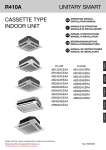
CASSETTE TYPE AIR CONDITIONER
DC INVERTER
Operation & Installation
Manual
AB092ACERA
AB142ACERA
AB182ACERA
Please read this operation manual before using the air conditioner.
Please keep this manual carefully and safely.
* No.0010576955 A
Contents
Cautions ........................................................................................... 1-2
Main Points of Operation................................................................
Name of Each Part ............................................................................
3-4
5
Safety Cautions................................................................................ 6-7
Maintenance ...................................................................................
8-9
When Trouble Happens ...................................................................... 10
Customer Need-to-know ................................................................... 11
Installation Tools ................................................................................ 12
Installation Procedures ................................................................. 13-20
Trouble Shooting.......................................................................... 21-23
Installation Procedures,Check and Test Run ..................................... 24
Cautions
Disposal of the old air conditioner
Consult your local authorities for the name and
address of the waste materials collecting
centers and waste paper disposal services
nearest to your house.
Before disposing an old air conditioner
that goes out of use, please make sure it's
inoperative and safe. Unplug the air
conditioner in order to avoid the risk of
child entrapment.
It must be noticed that air conditioner
system contains refrigerants, which require
specialized waste disposal. The valuable
materials contained in a air conditioner can
be recycled. Contact your local waste
disposal center for proper disposal of an
old air conditioner and contact your local
authority or your dealer if you have any
question. Please ensure that the pipework
of your air conditioner does not get
damaged prior to being picked up by the
relevant waste disposal center, and
contribute to environmental awareness by
insisting on an appropriate, anti-pollution
method of disposal.
Safety Instructions and Warnings
Before starting the air conditioner, read the
information given in the User's Guide
carefully. The User's Guide contains very
important observations relating to the
assembly, operation and maintenance of the
air conditioner.
The manufacturer does not accept
responsibility for any damages that may
arise due to non-observation of the following
instruction.
Damaged air conditioners are not to be
put into operation. In case of doubt, consult
your supplier.
Use of the air conditioner is to be carried
out in strict compliance with the relative
instructions set forth in the User's Guide.
Disposal of the packaging of your new
air conditioner
Installation shall be done by professional
people, don't install unit by yourself.
All the packaging materials employed in
the package of your new air conditioner
may be disposed without any danger to the
environment.
For the purpose of safety, the air
conditioner must be properly grounded in
accordance with specifications.
Always remember to unplug the air
conditioner before opening inlet grill. Never
unplug your air conditioner by pulling on the
power cord. Always grip plug firmly and
pull straight out from the outlet.
The cardboard box may be broken or cut
into smaller pieces and given to a waste
paper disposal service. The wrapping bag
made of polyethylene and the polyethylene
foam pads contain no fluorochloric
hydrocarbon.
All these valuable materials may be taken to a
waste collecting center and used again after
adequate recycling.
The air breaker should be all-pole switch.
and the distance between it's two connecters
should be no less than 3mm.
* **be
1
Cautions
All electrical repairs must be carried out
by qualified electricians. Inadequate repairs
may result in a major source of danger for
the user of the air conditoiner.
Do not damage any parts of the air
conditioner that carry refrigerant by
piercing or perforating the air conditioner's
tubes with sharp or pointed items, crushing
or twisting any tubes, or scraping the
coatings off the surfaces. If the refrigerant
spurts out and gets into eyes, it may result
in serious eye injuries.
Do not obstruct or cover the ventilation
grille of the air conditioner. Do not put
fingers or any other things into the
inlet/outlet and swing louver.
Do not allow children to play with the air
conditioner. In no case should children be
allowed to sit on the outdoor unit.
2. If the supply cord is damaged, it must be
replaced by the manufacturer or its service
agent or a similar qualified person.
3. If the fuse on PC board is broken please
change it with the type of T3.15A /250VAC.
4. The wiring method should be in line with
the local wiring standard.
5. Use copper wire only. The connecting cable
should be H05RN-F 4G 0.75mm2 . The power
cable should be H05RN-F 3G 2.5mm2 .
All the cables shall have got the European
authentication certificate.
6. The waste battery shall be disposed properly.
7. The indoor unit installation height is at least
2.5m.
8. The appliance must be installation that the
plug should be easily accessible after
installation.
9. The power plug should be self-provided and
it should have got the Local authentication certificate.
Specifications
The refrigerating circuit is leak-proof.
The machine is adaptive in following
situation
1. Applicable ambient temperature range:
Rated Maximum Minimum
32
18
DB C 27
Indoor
23
14
WB C 19
Cooling
DB
C
35
43
-5
outdoor
WB C 24
26
-27
15
Indoor DB C 20
Heating
--WB C 14.5
7
24
-15
outdoor DB C
18
-WB C 6
2
Main points of Operation
Operation of Air Conditioner
When the environmental humidity is great,
water maybe dripped from the air outlet in
cooling or drying mode.
3-minute Protection Function
If restart the unit immediately after stopping,
the compressor will start only 3 minutes later
to protect the machine.
Variation of Fan Speed
If fan speed in auto mode, it will automatically
lower when the room temperature close to the
setting temperature in cooling mode.
In heating mode,the compressor stops when the
room temperature at setting temperature and fan
turns into low speed or stops.
In Dry mode,fan speed will be automatically varied.
Remote Control:
There is a telecommunication interface for remote control on the control
panel of the indoor unit. After the peripheral equipment have been installed
in accordance with the instruction manual of the selected remote control
detector, the air conditioner will be computerized and controlled from a faraway place.
3
Main points of Operation
Prevent Cool Air Blowing Off
Wait a
minute
In heating mode,the indoor fan will not run
immediately after the unit starts to prevent
the cool air blowing off.
Defrosting Function
In heating mode, when frost formed on the outdoor heat
exchanger, the air conditioner will automatically defrost a
few minutes. During defrosting, both indoor and outdoor
fan will stop running. When defrosting finished, air conditioner will automatically back to running.
Defrosting Running
Hints
The air conditioner absorbs heat form outside and
releases inside when in heating mode, therefore the
outside environmental temperature will affect heating
effects.
Power Failure Compensation(to be applied for a necessary situation):
After the power failure compensation is set, if power failure suddenly occurs while the air
conditioner is working,it will resume the previous working state when the power is supplied
again.
Setting Method: When the remote controller is on (excluding timer mode and fan mode),press
the ìsleepingî button on the remote controller 10 times within 5 seconds,and
after the buzzer rings 4 times, the air conditioner will enter the state of power
failure compenstation.
Cancel Method:Press the ìsleepingî button on the remote controller 10 times within 5 seconds,
and after the buzzer rings 2 times, the power failure compensation mode will be
cancelled.
Note: When a power failure suddenly occurs during the air conditioner is working after the
power failure compensation is set,if the air conditioner will not be used for a long
time, please cut off the power supply to prevent its operation from being resumed
after the power is supplied again, or press the ì Switch On/Off î button after the power
comes again.
4
Name of Each Part
Indoor unit
Swing louver
(Air flow direction can be adjusted by using
the SWING button on the remote controller)
Operating Control Panel
Air Inlet Grille
Air Filter
(Inside of the Inlet Grille)
outdoor unit
Air inlet
Connecting piping
and electrical wiring
Drain hose
Air outlet
5
Safety Cautions
Carefully read the following information in order to operate the air conditioner correctly.
Below are listed four kinds of Safety Cautions and Suggestions:
WARNING: Incorrect operations may result in severe consequences of death or serious injures.
CAUTION : Incorrect operations may result in injures or machine damages; in some cases may
cause serious consequences.
: It must be strictly prohibited where marked with ì Prohibited î, otherwise may result in
machine damages or endanger the userípersonal safety.
INSTRUCTION: This information can ensure the correct operation of the machine.
Be sure to conform with the following important Safety Cautions.
The Safety Cautions should be at hand so that they can be checked at any time when needed.
If the air conditoner is transferred to the new user, this manual should be as well transferred to the new
user.
WARNING
Call the dealer to take measures to prevent the
refrigerant from leaking.
If any abnormal phenomena are found (e.g.
smell of firing),please cut off the power supply
immediately, and contact the dealer to find outí
the handling method.
In such case,to continue using
the air conditioner will damage
the conditioner,and may cause
electrical shock or fire hazard.
The leaked refrigerant over certain density may
cause oxygen deficient.If the air conditioner is
installed in a small room be sure to take measure
in order to prevent suffocation accident even in
case of refrigerant leakage
Switch
off
When air conditioner is removed and reinstalled
dealer should be responsible for them.
Incorrect installation may cause water leaking,
electrical shock and fire hazard.
When need maintenance and
repair,call dealer to handle it.
Donít dismantle the outlet of the outdoor unit.
Incorrect maintenance and repair
may cause water leak,
electrical shock and fire hazard.
The exposure of fan is very
dangerous witch may harm
human beings.
Donít put figures or any other
things into the inlet/outlet and
swing louver while the conditioner is in operation
After a long time use of air conditioner the base
should be checked for any damages.
If the damaged base is not
repaired, the unit may fall
down and cause accidents.
Because the high-speed fan
is very dangerous and may cause
injures.
6
Safety Cautions
WARNING
No goods or nobody is permitted
to be placed on or stand on
outdoor unit.
Donít clean air conditioner
with water.
Otherwise may cause shock.
The falling of goods and
people may cause accidents.
Don't operate the air conditioner with
damp hands.
Connect earthing wire.
Earthing wire should not be
connected to the gas pipe,
water pipe,lightning rod or
phone line,incorrect earthing
may cause shock.
Otherwise will be shocked.
Only use correct type fuse.
May not use wire or any other
materials replacing fuse,otherwise may cause faults or fire
accidents.
Use discharge pipe correctly to
ensure efficient discharge.
In correct pipe usage may cause water
leaking.
Donít place any burning
unit in the airflow of air
conditioner,which may
cause incomplete
combustion
Air conditioner canít be be installed in
the environment with inflammable gases.
The inflammable gases near to air conditioner
may cause fire hazard.
Installed electrical-leaking circuit breaker.
It easily causes electrical shock without
circuit breaker.
No inflammable spray fluid
should be permitted to be
placed or used near to air
conditioner,otherwise may
cause fire accident.
Air conditioner should be
cleaned only after power
supply is cut off to keep
from shock or hurt.
When use the fumigating insecticide
donít operate air conditioner.
Otherwise the poisonous chemicals
may settle in air conditioner,
which harm the health of
chemical-allergic people.
Not permitted
when running
7
Maintenance
Clean the unit
Turn off the power supply switch
Do not touch with wet hand.
Do not use hot water or volatile liquid
ON
OFF
The 4 fixed bolts must be loosed as shown in
the figure by arrow if they are bolts, the method
is that: push the blots inward till to another edge.
Fixing nolt
Fixing nolt
Rotary fixing clamp
Fixing nolt
Clean the air filter
Clean the air filter with water or vacuum cleaner.
Use the detergent or neutral soapy water if the
air filter is too dirty. Then rinse the air filter with
water,and reinstall after drying.
Caution:
Do not clean the air filter with hot water over 40 C,
otherwise may damage the filter.
Sweep the filter carefully.
Clean indoor (outdoor )unit
Clean with hot wet cloth and neutral detergent, then wipe with
dry cloth.Do not use too hot water (over 40 C) which may result
in fading and deforming. Do not use insecticide and chemical
washing agent.
8
Outward drawable filter
Maintenance
Seasonal Reserve
Post-season Care
Operate the unit with FAN mode on a fair day for about half
a day to dry the inside of the unit well.
Stop operation and turn off the power supply switch .Electric
power is consumed even the air conditioner is in stop.
Clean the air filter, indoor unit and outdoor unit,and cover
the unit with dustcoat.
Pre-season Care
See that there is no obstacle blocking the air
inlet and air outlet of both indoor and outdoor
unit to avoid reduce the working efficiency.
Be sure to install the air filter, ensure that the air filter is not dirty. Otherwise may result in
machine damages or cause malfunciton due th dust inside the unit
To protect compressor when start in HEAT mode,
please cut in the power supply switch 12 hours
before starting run,furthermore, always keep the
power supply switch on during the using senson.
9
When Trouble Happens
Insufficient cooling or heating
The operation controller
adjusted as required
Any obstacle exists at the air
inlet or outlet?
Air filter too dirty ?
Horizontal swing louver
upward ? (in HEAT mode)
Door or window left opened ?
Insufficient cooling
Any other heat sources in the
room?
Sunlight direct into the
room ?
Too crowed in the room ?
Cooled air blown out ( when heating)
When the air conditioner does not operate properly after
you have checked the above-mentioned items or when
following phenomenon is observed,stop the operation of
the air conditioner and contact your sales dealer.
The fuse or breaker often shuts down.
Water drops off during cooling or drying operation.
There is an irregularity in operation or abnormal sound that
is audible.
10
Customer Need-to-know
Customer Need-to-know
Please install the air conditioner according to the requirements specified in this manual to ensure
the air conditioner work well.
Be careful not to scratch the surface of the case during moving the air conditioner.
Please keep the installation manual for future reference when maintenance and changing installation
place.
After installation ,please use the air conditioner according to the specification in the operation
manual.
Using Directions
Avoid direct sunlight and airflow
Adjust suitable airflow direction
Keep the proper indoor temperature.
Too cool or hot is not good for your health.
Furthermore,it will result in excessive
consumption of electric power.
Effectively use timer.
Using TIMER mode, you can make the room
temperature reach a suitable temperature when
you wake up or back home.
Optimal
temperature
ATTENTION: after finishing installation, please confirm no refrigerant leakage.
11
Installation Tools
Installation tools
The installation tools listed in the
following sheet can be used as required.
1. Screw driver
2. Hacksaw
3. Drill with a diameter of 60mm
4. Inner hexagon spanner,shifting
spanner
5. Spanner (14, 17, 19,24,27mm)
6. Pipe cutter
7. Pipe expander
8. Knife
9. Pincers
10. Leakage detector or soapy water
11. Band tape
12. Scraper
13. Refrigerant oil
The following parts mentioned in this
manual are the installation accessories
we prepared.
Symbol
Parts Name
A
Adhesive tape
B
Pipe clamp
C
Connecting hose
D
Drainage hose
E
Non-hydroscopic
heat insulating material
F
Gypsum powder
12
Installation Procedures
Installation of Outdoor Unit
Selection of installation place
Place strong enough to support unit weight, and will not cause vibration and noise.
Place where discharged wind and noise do not cause nuisance to the neighbors, and is sufficiently
ventilated.
Place where is less affected by rain or direct sunlight and sea breeze.
Place with enough space for smooth air flow.
The unit cannot be installed on an unspecified metal frame (e.g. theft guard net).
It shall be not less than 2.5m high from the ground if the outdoor unit is installed close to a street.
Easy for maintenance.
Fixing the unit
319.5
Fix outdoor unit bracket to the wall using anchor bolt (M10).
Fasten the outdoor unit onto the installation bracket with bolt (M10) and nut ,and keep it horizontal.
If installation on the wall or on top of a roof, bracket shoukd be fixed securely to resist earthquake or
storms.
Be sure to use rubber pad during installation against unit vibration.
Install the unit in such a way that the angle of inclination is lees than 3 degrees.
113.5
583
113.5
AU182AFERA
Installation dimension of outdoor unit (mm)
13
Installation Procedures
1.Selection of Installation Place
(1) Place above the ceiling where have enough space to arrange the unit.
(2) Place where the drainage pipe can be arranged well.
(3) Place where inlet and outlet air of indoor and outdoor unit will not be blocked.
(4) Do not expose the unit to the place with heavy oil or moisture (e.g.kitchen and workshop).
(5) Do not set the unit in the place where destructive gas (such as sulfuric acid gas) or pungent
gas (thinner and gasoline) concentrates and retains.
(6) Place strong enough to support the unit weight.
Air outlet
Air inlet
0.31m
H
(7) No expensive articles such as television and piano below indoor unit.
(8) Enough space for maintenance.
(9) Place more than 1m away from television and radio to avoid disturbing television and radio.
(10) Easy for maintenance.
Air outlet
1.5m
1.5m
2.5m Over
2.Installation Preparation
Overlap between ceiling and
ornament panel shall be 25mm
Ceiling
Distance between
suspending bolts 535mm
Ornament panel
320mm
150mm
Suspending bolts
60mm
Ceiling opening 650mm
Ornament panel 700mm
Indoor unit 570mm
(1) Position of ceiling opening between unit and suspending bolt (front view of unit).
Indoor unit 570mm
Ceiling opening 650mm
Ornament panel 700mm
(2) Prepare all piping (refrigerant,water drainage )and wires (connection wire of remote controller,
indoor unit connection wires) to the indoor unit before installation in order to connect indoor unit
immediately after installation.
14
Installation Procedures
(3) Install a suspending bolt
To support the unit weight ,anchor bolt should be used in the case of
already exists ceiling. Fow new ceiling, use flush-in type bolt, built-in
type bolt or parts pretared in the field.
Before going on installing, adjust space to ceiling.
50 ~150mm
Roof
Anchor bolt
Long nut or thread
Suspending bilt M10
Ceiling
Note: All the above mentioned parts shall be prepared in feild,
the diameter of suspending bolt is M10
3. Installation of indoor unit
<Installation Example>
In case of no ceiling
Install unit temporally
Put suspending bracket on the suspending bolt to hang the unit up. Be sure to use nut and
washer at both end of the breaket to secure firmly.
After installation on the ceiling
(1) Adjust unit to its right position (Refer to preparation for installation-(1))
(2)Check that unit is horzontal.
Water pump and floating switch is installed inside indoor unit,check four corners of the unit for
its lever using horizontal comparator or PVC tube with water.(If unit is tilting against the direction
of water drainage,problem may occur on floating water leakage.)
Nut (Prepare in feild)
Washer (Prepared in feild)
In the case of ceiling already exists
(1)Install unit temporally
Put suspending bracket on the suspending bolt to hang the
unit up.Be sure to use nut and washer at both end of the
bracket to secure it firmly.
(2)Adjust the height and position of the unit.
(3)Proceed with procedure (4) of " In the case of no ceiling "
Suspending bolts
Fasten (double nuts)
Insert
leveler
Washer fixing pad
(prepared in feild)
[ secure the washer firmly]
Polythene pipe
15
Installation Procedures
4. Installation of water drainage pipe
(1) Install water drainage pipe
Pipe diameter shall be equal or larger than that of connecting pipe (Pipe of polythene; size:
25mm; O.D.: 32mm )
Drainpipe should be short, with a downward slope at least 1/100 to prevent air bag from forming.
If downward slope of drainpipe cannot be made,lifting pipe shall be installed.
Keep a distance of 1-1.5m between suspending bolts, to make water hose straight.
1-1.5m
slope over 1/100
Use the drainage hose and clip provided with unit.
Insert water pipe into water plug until it reaches the white tape.
Tighten the clip until head of the screw is less than 4mm from hose.
Wind the ddrainage hose to the clip using seal pad for heat insulation.
Insulate drainage hose in the room.
Large size seal pad
(accessory)
Clip
Tape(white)
Clip
Draingage hose
4mm below
5. Cautions for the water drainage lifting pipe
Installation height of water drainage lifting pipe shall be less than 280mm
220mm
Clip
500mm below
Drainage hose
500mm below
220
300mm below 1-1.5m Suspending bracket
280mm unter
Drainage hose
Water drainage
lifting pipe
75mm below
There should be a right angle with unit ,300mm from unit.
< Note >
The slope of water drainage hose shall be within 75mm , make the drainage plug not to bear
excessive force.
100mm ¸over
If several water hoses join together, of as per following procedures.
Slope below 1/100
Connection drainage hose with a T-joint
Specifications of the selected drainage hoses shall meet the requirements for the unit running
16
Installation Procedures
6. Installation of Ornament Panel
Install ornament panel on indoor unit
(1) Check whether indoor unit is horizontal with leveler or polythene pipe filled with water , and
check that the dimension of the ceiling opening is correct. Take off the lever gauge before install
the ornament panel.
(2) Fasten the screws to make the height difference between the two sides of indoor unit less than
5mm.
(3) First fix it with screws temporally.
(4) Fasten the two temporally fixing screws and other two, and tighten the four screws.
(5) Connect the wires of synchro-motor.
(6) Connect the wire of signal.
(7) If no response of remote controller,check whether the wiring is correct,restart remote controller
10 seconds after shut off power supply.
Control box
Limits of panel board installation
(1)Install the panel board in the direction shown in
the figure.
(2)The incorrect direction will result in water leakage,
meanwhile swing and signal receiving are displayed
that cannot be connected.
17
Installation Procedures
Piping Connection
Flare connection
3-way valve
Gas pipe
Indoor
Unit
Outdoor
unit
Liquid
pipe
2-way valve
Flare connection
(1) Dimension of connecting pipe
Gas pipe
12.7mm
Liquid pipe
6.35mm
Fit the nut on and fasten
(2) The maximum length and drop height of connecting pipe
The maximum length is 20m
The maximum drop height is 10m.
Joint
To ensure the efficiency ,Pipes shall be as short as possible.
Spanner
Cautions for piping connection
Do not twist or deform the connecting pipe.
Do not mix dusts.
The bending radius shall be as large as possible.
Both gas pipe and liquid pipe shall be heat insulation.
Spanner
Nut
No leakage in the flare.
(3) Piping connection
Connecting method
Smear refrigerant oil on the joints of piping and flare.
The bending radius shall be as large as possible.
Align the pipe center when fastening, and tighten the
nut, as shown in the figure.
Pay attention to not mix foreign matters such as sands
in.
18
Diameter of Pipe
Tighten Torque
(N. m)
Liquid Pipe 6.35mm
11.8
Gas Pipe 12.7mm
49.0
If not aligned ,tighten the nut by force will
damage the nut that result in gas leakage
Installation Procedures
(4) Purging method ( the refrigerant is R410A)
Liquid pipe
6.35mm(1/4'')
To use vacuum pump
1
Gas pipe
2-way valve
Detach the service port's cap of 3-way valve, the
valve rod's cap for 2-way valve and 3-way's, connect
the service port into the projection of charge hose
(low) for gaugemanifold. Then connect the projection
of charge hose (center) for gaugemanifold into
vacuum pump.
12.7mm(1/2'')
3-way valve
1
Gaugemanifold (R410A)
Vacuum pump(R410A)
2
Open the handle at low in gaugemanifold, operate
vacuum pump. If the scale-moves of gause (low)
reach vacuum condition in a moment, check 1 again.
2 Open
3
Vacuumize for over 15min. And check the level gauge
which should read -0.1 MPa (-76 cm Hg) at low
pressure side. After the completion of vacuumizing,
close the handle 'Lo' in gaugemanifold and stop the
operation of the vacuum pump.
Check the condition of the scale and hold it for 1-2min.
If the scale-moves back in spite of tightening, make
flaring work again, the return to the beginning of 3 .
3 Close
2-way valve
4
3-way valve
90
Open the valve rod for the 2-way valve to and angle of
anticlockwise 90 degree.
After 6 seconds later, close the 2-way valve and male
the inspection of gas leakage.
5
No gas leakage?
90
Service port
4 90 for 6 sec.
If it does not stop gas leakage, discharge
whole refrigerants from the serice port.
After flaring work again and vacuumize,
fill up prescribed refrigerant from the gas
cylinder.
In case of gas leakage, tighten
parts of pipe connection. If
leakage stops, then proceed 6
steps.
6
Detach the charge hose from the service port, open
2-way valve and 3-way. Turn the valve rod
anticlockwise until hitting lightly.
2-way valve
6
3-way valve
7
6
To prevent the gas leakage, turn the service port's
cap, the valve rod'd cap for 2-way valve and 3-way's
a lottle more than the point where the torque increases
suddenly.
8
2-way valve
After attaching the each caps, check the gas leakage
around the caps.
3-way valve
7 Valve rod cap
CAUTION:
If the refrigerant of the air conditioner leaks, it is necessary to make
all the refrigerant out, then charge the liquid refrigerant into air
conditioner according to the amount marked on the name plate.
19
7 Valve rod cap
7 Service port cap
Installation Procedures
Electrical Wiring
Cautions: Use copper wire only.Parameters of connecting
line : H05RN-F 4G0.75mm2
Power supply :1PH,220-230V~,50Hz, connect from outside.
L
Wiring methods:
1.Wiring method of ring terminal
For connecting line which end is a ring,its wiring method
as shown in the right figure: remove wiring screw and pass
it through the end ring of connecting line,then connect it to
the terminal block and tighten screw.
2. Wiring method of straight terminal
Wiring method of ring terminal
Terminal block
For connecting line which end is not a ring, its wiring method
as follows: loosen wiring screw ans insert the end of connecting
line totally into the terminal block,then tighten the screw and pull
the connecting line slightly to confirm that it is clamped firmly.
Crimp connection
clamp
Crimp connection method of connecting line
After finishing wiring.connecting line must be fastened by
wire clamp,which pressed on the external sheath of the
connecting line, as shown in the right figure:
Wiring of indoor unit
Open air inlet grill
Take the leading end of connecting line
Connect connecting line according to wiring methods
and wiring diagram of indoor and outdoor unit
Fasten connecting line according to crimp connection
method of connecting line.
Reinstall air inlet grill.
Incorrect crimp
connection of wire
Correct crimp
connection of wire
L
N
1
2 3
1
2
Indoor unit
terminal block
Outdoor unit
terminal block
3
Power supply:1PH,220-230V~,50Hz
1.Installation fixing
Fix outdoor unit installation bracket on the wall using a
M10 anchor bolt.Fix outdoor unit on the installation bracket
firmly using bot(M10) and nut, and keep it on horizontal level.
When installing on the wall or on the roof ,fix the bracket,
firmly to prevent earthquake or storm.
Be sure to use rubber-damping cushion to reduce unit vibration.
2.Installation of drain elbow
Installation of drain elbow.(Only for heat pump type air conditioner,
no drain elbow for single cooling type).If use drain elbow,please
install as shown in the figure.
Do not use drain elbow in cold place (temperature successively
below 0 C)
Terminal
Wire clamp
Power supply
Connecting wire
between inner and outer
3. Connection of outdoor piping
Connect the connecting pipe according to the piping connection
method
4.Wiring connection
1.Open the wiring cover and loosen the wiring clamp.
2.Lead the connecting wire out and pass it through the wiring clamp.
3.Connect the connecting wire according to the wiring method and
diagram
4. Confirm the ends of wire are connected well, safe and correct.
5. After finishing wiring, press the connecting wire according to the
wire crimp connection method and reinstall the cover.
20
L
N
1
2
3
Trouble Shooting
The followings are not malfuncition
When the air conditoner is started, when the
compressor starts or stops during operation
or when the air conditioner is stopped,it sometimes sounds ì Bi- Bi-î or ìGodo-Godoî. It is
the flowing sound of the refrigerant , not a
malfunction.
Water flowing sound is heard
Hua
Hua
Cracking sound is heard
This is caused by heat expansion or contraction of plastics
It smells.
Air blown out from the indoor unit sometimes
smells. The smell results from smells of
furniture, paint , tobacco absorbed by indoor
unit.
During operation, white fog comes out of
indoor unit.
When in COOL or DRY mode, a thin water
fog can be seen blown out of unit ,this is the
condensed fog because the suddenly cooled
indoor air is blown out.
Automatically switch into FAN mode during
cooling.
To prevent frost from being accumulated on the
indoor unit heat exchanger, it sometimes automatically switched into the FAN mode,but it will
soon back to the cooling mode.
The air conditioner cannot be restarted soon
after it stops.
Air conditioner does not start?
This is because of the self-protection function
of the system, therefore,it cannot be restarted
for about three minutes after it stops.
Please wait for
three minutes
21
Trouble Shooting
Air does not blow or the fan speed cannot be
changed during drying.
In DRY mode, when room temperature
becomes 2 C higher than temperature setting,
unit rill run intermittently at LO speed regardless
of FAN setting
This happens when the frost accumulated on
the outdoor unit is removed (during defrosting
operation).
Water or vapor generated from the outdoor
unit during heating.
Defrosting operation
During heating,indoor fan is still running even
unit is stopped.
To get ride of the excess heat, indoor fan will
continue running for a while after unit automatically stops.
Please check the following things about your air conditioner before making a
service call.
Unit fails to start.
Is the power supply switch on ?
Is city supply power normal ?
Is the earth leakage breaker
in action ?
**?
ON
OFF
Power supply switch is not in
ON position.
Be sure to turn off the power
supply switch immediately and
contact the sales dealer.
22
23
Communication abnormal for more than 4m continuously
Communication abnormal for more than 4m continuously
Float switch broken down for more than 25m continuously
Outside signal broken down for more than 10s
Sensor broken down or short circuit for more than 2m continuously
Solenoid valve act incorrectly 3 times continuously
Sensor broken down or short circuit for more than 2m continuously
EEPROM data missing
Low pressure switch acts in normal running
CT check abnormal 3 times in 30m
High pressure switch acts 3 times in 30m
Fault phase, short of phase, out of balance greatly
Sensor broken down or short circuit for more than 2m continuously
Sensor broken down or short circuit for more than 2m continuously
Sensor broken down or short circuit for more than 2m continuously
Sensor broken down or short circuit for more than 2m continuously
Reason
17
Compressor overheat
The discharging temperature is higher than 120degree
18
Abnormal mode
Indoor operation mode is different with the running indoor unit.
19
Outdoor coil B(suction temp sensor-for MRV II)
Sensor broken down or short circuit for more than 2m continuously
20
Outdoor discharging B(oil temp sensor-for MRV II) Sensor broken down or short circuit for more than 2m continuously
shows resumable fault, * shows it is not resumable fault.
For remote Failure description
type, flash
times
1
Indoor ambient temp. sensor failure
2
Indoor coil temp. sensor failure
3
Outdoor ambient temp. sensor failure
4
Outdoor coil temp. sensor failure (compressor
discharging temp. sensor)
5
Over-current protection
6
High pressure abnormal
7
Power supply abnormal
Communication between wired
8
controller and indoor abnormal
9
Communication between indoor and outdoor abnormal
10
Drainage system abnormal
11
Outside alarm signal input
12
Gas pipe temp. sensor abnormal
13
Solenoid valve abnormal
14
Discharging temp. sensor abnormal
15
EEPROM abnormal
16
Pressure abnormal(low pressure)
Resumable if
lower than 100
degree
Remarks
Trouble Shooting
Installation Procedures,Check and Test Run
Other Instructions
1.Configuration of power supply
Air conditioner must use special power supply system (above 20A), and qualified electrician makes
wiring and fixing according to wiring regulations specified in national standard.
In socket, exactly distinguish earth wire with neutral wire and it is wrong to connect them together.
A leakage breaker must be installed.
Parameters of power supply: H07RN-F 3G 2.0mm2
Connection method is Y-connection .If the power cord is damaged, it must be replaced by
professional people of manufacturer or its maintenance department or similar to avoid dangers.
2.Pipe cutting and expanding
Must remove burrs if cut pipes with pipe cutter.
Expand flare after insert the pipe expander.
Diameter of pipe
Dimension A (mm)
A
Liquid pipe
6.35mm (1/4î)
1.0~1.2
Gas pipe
12.7mm (1/2î)
1.4~2.2
Pipe expander
Incorrect
Correct
Deflection
Crack occurs
Broken
Incomplete
Over outward
Installation check and test run
Require customers to use air conditioner according to the operation manual.
The items checked during test run,please mark
in
No gas leakage on the pipe joint ?
How about the thermal insulation of the pipe joint:
Is the electrical wiring between indoor and outdoor unit connected to the terminal block firmly?
Is the wiring of indoor and outdoor unit secured firmly?
Is the drainage hose arranged correct?
Is the earthing wire connected firmly?
Is the power supply voltage conformed to the electrical regulation?
Any noise?
Is the display on the control board (LCD) correct?
Cooling normal?
Does the indoor temperature regulator work normally?
For the power supply
L shall be connected to the live wire.
N shall be connected to the neutral wire.
Shall be connected to the earth wire.
24