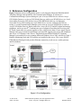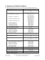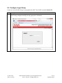
1
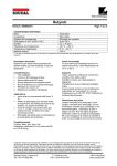
Avaya Solution & Interoperability Test Lab Application Notes for Integrated Research PROGNOSIS IP Telephony Manager 9.6 with Avaya Aura® Communication Manager - Issue 1.0 Abstract These Application Notes describe the procedures for configuring Integrated Research PROGNOSIS IP Telephony Manager 9.6 to interoperate with Avaya Aura® Communication Manager 6.0.1. PROGNOSIS IP Telephony Manager is a performance management solution for multi-vendor IP telephony solutions. PROGNOSIS IP Telephony Manager provides visibility of Avaya and other vendor’s IP Telephony solutions from a single console. Targeted at multi-site enterprises and managed service providers of IP telephony solutions, PROGNOSIS IP Telephony Manager offers a multi-customer, multi-PBX perspective, enabling a significant reduction in complexity when managing complex IP telephony environments. PROGNOSIS integrates directly to Communication Manager using Secure Shell (SSH). At the same time, it processes Real-time Transport Control Protocol (RTCP) and Call Detail Recording (CDR) information from Communication Manager. Information in these Application Notes has been obtained through DevConnect compliance testing and additional technical discussions. Testing was conducted via the DevConnect Program at the Avaya Solution and Interoperability Test Lab. JC; Reviewed: SPOC 6/16/2011 Solution & Interoperability Test Lab Application Notes ©2011 Avaya Inc. All Rights Reserved. 1 of 30 IPTM96-CM601 1. Introduction These Application Notes describe the compliance tested configuration used to validate Integrated Research PROGNOSIS IP Telephony Manager with Avaya Aura® Communication Manager. The PROGNOSIS IP Telephony Manager is based on the PROGNOSIS product-family architecture for the scalable monitoring of business critical systems. The PROGNOSIS product consists of: One or more PROGNOSIS Monitoring Nodes (Server Nodes). These are servers used by the PROGNOSIS product to collect, relay and store information collected from Communication Manager. The PROGNOSIS GUI is a Microsoft Windows client program which is used to connect to a PROGNOSIS Monitoring Node and display the information collected by the Monitoring Node. The PROGNOSIS GUI may either be installed on a Monitoring Node or on a separate computer. The PROGNOSIS IP Telephony Manager product uses three methods to monitor a Communication Manager system. System Access Terminal (SAT) - The PROGNOSIS IP Telephony Manager uses a pool of SSH connections to the SAT using the IP address of the Avaya Server. By default, the solution establishes three concurrent SAT connections to the Communication Manager system and uses the connections to execute SAT commands. Real Time Transport Control Protocol (RTCP) Collection - The PROGNOSIS IP Telephony Manager collects RTCP information sent by the Avaya IP Media Processor (MEDPRO) boards, media gateways, IP Telephones and IP Softphones. Call Detail Recording (CDR) Collection - The PROGNOSIS IP Telephony Manager collects CDR information sent by Communication Manager. 2. General Test Approach and Test Results The general test approach was to use PROGNOSIS GUI to display the configurations of the Communication Manager systems and verify against what is displayed on the SAT interface. The SAT interface is accessed by using either telnet or Secure Shell (SSH) to the Avaya S8800 and S8300D Servers. Calls were placed between various Avaya endpoints and PROGNOSIS GUI was used to display the RTCP and CDR information collected. JC; Reviewed: SPOC 6/16/2011 Solution & Interoperability Test Lab Application Notes ©2011 Avaya Inc. All Rights Reserved. 2 of 30 IPTM96-CM601 2.1. Interoperability Compliance Testing For feature testing, PROGNOSIS GUI was used to view the configurations of Communication Manager such as port networks, cabinets, media gateways, ESS, LSP, trunk groups, route patterns, CLAN, MEDPRO and DS1 boards, IP network regions, stations, processor occupancy, alarm and error information. During testing, a call generator was used to load the Communication Manager systems by placing incoming calls through two E1 ISDN-PRI trunks to the system in Site A and terminating the calls as IP stations on the system in Site B. For the collection of RTCP and CDR information, the endpoints included Avaya IP, digital and analog telephones, Avaya A175 Desktop Video Device and Avaya one-X® Communicator users. The types of calls made included intra-switch calls, inbound/outbound inter-switch IP trunk calls, transferred calls and conference calls. For serviceability testing, reboots were applied to the PROGNOSIS IP Telephony Manager Server and Avaya Servers to simulate system unavailability. Interchanging of the Avaya S8800 Servers and failover to ESS and LSP were also performed during testing. 2.2. Test Results All test cases passed successfully. 2.3. Support For technical support on Integrated Research PROGNOSIS IP Telephony Manager, contact the Integrated Research Support Team at: Hotline: +61 (2) 9921 1524 Email: [email protected] JC; Reviewed: SPOC 6/16/2011 Solution & Interoperability Test Lab Application Notes ©2011 Avaya Inc. All Rights Reserved. 3 of 30 IPTM96-CM601 3. Reference Configuration Figure 1 illustrates the test configuration used to verify Integrated Research PROGNOSIS IP Telephony Manager interoperability with Communication Manager. It consists of a Communication Manager system running on a pair of Avaya S8800 Servers with two Avaya G650 Media Gateways, an Avaya G430 Media Gateway with Avaya S8300D Server as a Local Survivability Processor (LSP) and an Avaya G250-BRI Media Gateway. An Enterprise Survivable Server (ESS) running on Avaya S8800 Server was also configured for failover testing. A second Communication Manager system runs on an Avaya S8300D Server with an Avaya G450 Media Gateway. Both systems have Avaya IP (H.323 and SIP), digital and analog telephones, and Avaya one-X® Communicator users configured for making and receiving calls. IP Trunks connect the two systems together to allow calls between them. Avaya Aura® System Manager and Avaya Aura® Session Manager provided SIP support to the Avaya SIP telephones and Avaya A175 Desktop Video Device. Integrated Research PROGNOSIS IP Telephony Manager was installed on a server running Microsoft Windows Server 2003 with Service Pack 2. Both the Monitoring Node and GUI software are installed on this server. The Avaya 4548GTPWR Ethernet Routing Switch provides Ethernet connectivity to the servers, media gateways and IP telephones. Figure 1: Test Configuration JC; Reviewed: SPOC 6/16/2011 Solution & Interoperability Test Lab Application Notes ©2011 Avaya Inc. All Rights Reserved. 4 of 30 IPTM96-CM601 4. Equipment and Software Validated The following equipment and software were used for the sample configuration provided: Equipment Avaya S8800 Servers Avaya G650 Media Gateways - TN2312BP IP Server Interface - TN799DP C-LAN Interface - TN2302AP IP Media Processor - TN2602AP IP Media Processor - TN2214CP Digital Line - TN793CP Analog Line - TN2464BP DS1 Interface - TN2464CP DS1 Interface Avaya G250-BRI Media Gateway Avaya G430 Media Gateway - MM712AP DCP MM - MM714AP Analog MM - MM711AP Analog MM - MM710AP DS1 MM Avaya S8300D Server as LSP Avaya S8800 Server as ESS Avaya S8300D Server Avaya G450 Media Gateway - MM722AP BRI Media Module (MM) - MM712AP DCP MM - MM714AP Analog MM - MM717AP DCP MM - MM710BP DS1 MM Avaya Aura® System Manager Avaya Aura® Session Manager Avaya 9600 Series IP telephones - 9630, 9640, 9650, 9670G Avaya 1608 IP telephones Avaya 6221 analog telephones JC; Reviewed: SPOC 6/16/2011 Software Avaya Aura® Communication Manager 6.0.1 (Service Pack 1.01 00.1.510.1-18857) HW07, FW053 and HW15 FW054 HW01, FW039 and HW01 FW040 HW20 FW121 and HW20 FW117 HW02 FW058 and HW02 FW041 HW08 FW015 HW09 FW010 HW05 FW024 HW02 FW024 30.18.1 31.18.1 HW04 FW009 HW04 FW073 HW31 FW093 HW05 FW021 6.0.1 (Service Pack 1.01 00.1.510.1-18857) 6.0.1 (Service Pack 1.01 00.1.510.1-18857) Avaya Aura® Communication Manager 6.0.1 (Service Pack 1.01 00.1.510.1-18857) 31.18.1 HW01 FW008 HW07 FW009 HW10 FW093 HW03 FW009 HW11 FW049 6.1 Service Pack 2 6.1 Service Pack 2 3.1 SP2 (H.323) or 2.6 SP4 (SIP) 1.300B (H.323) - Solution & Interoperability Test Lab Application Notes ©2011 Avaya Inc. All Rights Reserved. 5 of 30 IPTM96-CM601 Equipment Avaya digital telephones - 1416 - 2420 Avaya A175 Desktop Video Device Avaya one-X® Communicator Avaya 4548GT-PWR Ethernet Routing Switch Integrated Research PROGNOSIS IP Telephony Manager Software SP1 1.0 6.0 SP1 (H.323) V5.4.0.008 9.6.1 Patch 11 5. Configure Communication Manager This section describes the steps needed to configure Communication Manager to interoperate with Integrated Research PROGNOSIS IP Telephony Manager. This includes creating a login account and a SAT User Profile for PROGNOSIS to access Communication Manager and enabling RTCP and CDR reporting. The steps are repeated for each Communication Manager system, ESS and LSP Servers. 5.1. Configure SAT User Profile A SAT User Profile specifies which SAT screens may be accessed by the user assigned the profile and the type of access to each screen. As PROGNOSIS IP Telephony Manager does not modify any system configuration, create a SAT User Profile with limited permissions to assign to the PROGNOSIS login account. Step Description 1. Enter the add user-profile n command, where n is the next unused profile number. Enter a descriptive name for User Profile Name and enable all categories by setting the Enbl field to y. In this configuration, the user profile 21 is created. add user-profile 21 Page 1 of 41 USER PROFILE 21 User Profile Name: IPTM This Profile is Disabled? n Facility Test Call Notification? n Grant Un-owned Permissions? n Name Cat Enbl Adjuncts A y Call Center B y Features C y Hardware D y Hospitality E y IP F y Maintenance G y Measurements and Performance H y Remote Access I y JC; Reviewed: SPOC 6/16/2011 Shell Access? n Acknowledgement Required? n Extended Profile? n Name Cat Enbl Routing and Dial Plan J y Security K y Servers L y Stations M y System Parameters N y Translations O y Trunking P y Usage Q y User Access R y Solution & Interoperability Test Lab Application Notes ©2011 Avaya Inc. All Rights Reserved. 6 of 30 IPTM96-CM601 Step Description 2. On Pages 2 to 41 of the USER PROFILE forms, set the permissions of all objects to rm (read and maintenance). This can be accomplished by typing rm into the field Set All Permissions To. Submit the form to create the user profile. add user-profile 21 Page 2 of 41 USER PROFILE 21 Set Permissions For Category: To: Set All Permissions To: rm '-'=no access 'r'=list,display,status 'w'=add,change,remove+r 'm'=maintenance Name Cat Perm aar analysis J rm aar digit-conversion J rm aar route-chosen J rm abbreviated-dialing 7103-buttons C rm abbreviated-dialing enhanced C rm abbreviated-dialing group C rm abbreviated-dialing personal C rm abbreviated-dialing system C rm aca-parameters P rm access-endpoints P rm adjunct-names A rm administered-connections C rm aesvcs cti-link A rm aesvcs interface A rm JC; Reviewed: SPOC 6/16/2011 Solution & Interoperability Test Lab Application Notes ©2011 Avaya Inc. All Rights Reserved. 7 of 30 IPTM96-CM601 5.2. Configure Login Group Create an Access-Profile Group to correspond to the SAT User Profile created in Section 5.1. Step Description 1. Using a web browser, enter https://<IP address of Avaya Server> to connect to the Avaya Server being configured and log in using appropriate credentials. JC; Reviewed: SPOC 6/16/2011 Solution & Interoperability Test Lab Application Notes ©2011 Avaya Inc. All Rights Reserved. 8 of 30 IPTM96-CM601 Step Description 2. Click Administration > Server (Maintenance). This will open up the Server Administration Interface that will allow the user to complete the configuration process. JC; Reviewed: SPOC 6/16/2011 Solution & Interoperability Test Lab Application Notes ©2011 Avaya Inc. All Rights Reserved. 9 of 30 IPTM96-CM601 Step Description 3. From the navigation panel on the left side, click Administrator Accounts under Security. Select Add Group and click Submit. JC; Reviewed: SPOC 6/16/2011 Solution & Interoperability Test Lab Application Notes ©2011 Avaya Inc. All Rights Reserved. 10 of 30 IPTM96-CM601 Step Description 4. Select Add a new access-profile group and select prof21 from the drop-down box to correspond to the user-profile created in Section 5.1 Step 1. Click Submit. This completes the creation of the login group. JC; Reviewed: SPOC 6/16/2011 Solution & Interoperability Test Lab Application Notes ©2011 Avaya Inc. All Rights Reserved. 11 of 30 IPTM96-CM601 5.3. Configure Login Create a login account for PROGNOSIS to access the Communication Manager SAT. Step Description 1. From the navigation panel on the left side, click Administrator Accounts. Select Add Login and SAT Access Only to create a new login account with SAT access privileges only. Click Submit. JC; Reviewed: SPOC 6/16/2011 Solution & Interoperability Test Lab Application Notes ©2011 Avaya Inc. All Rights Reserved. 12 of 30 IPTM96-CM601 Step Description 2. For the field Login name, enter a login to be used by PROGNOSIS. In this configuration, the login iptm is created. Configure the other parameters for the login as follows: Primary group: Select users [Limits the permissions of the login] Additional groups (profile): prof21 [Select the login group created in Section 5.2 Step 4.] Select type of authentication: Select Password [Uses a password for authentication.] Enter password or key / Re-enter password or key [Define the password.] Force password/key change on next login: Select No Click Submit to continue. This completes the configuration of the login. JC; Reviewed: SPOC 6/16/2011 Solution & Interoperability Test Lab Application Notes ©2011 Avaya Inc. All Rights Reserved. 13 of 30 IPTM96-CM601 5.4. Configure RTCP Monitoring To allow PROGNOSIS IP Telephony Manager to monitor the quality of IP calls, configure Communication Manager to send RTCP reporting to the IP address of the PROGNOSIS server. This is done through the SAT interface. Step Description 1. Enter the change system-parameters ip-options command. In the RTCP MONITOR SERVER section, set Server IPV4 Address to the IP address of the PROGNOSIS IP Telephony Manager server. Set IPV4 Server Port to 5005 and RTCP Report Period (secs) to 5. change system-parameters ip-options IP-OPTIONS SYSTEM PARAMETERS Page 1 of 3 IP MEDIA PACKET PERFORMANCE THRESHOLDS Roundtrip Propagation Delay (ms) High: 800 Low: 400 Packet Loss (%) High: 40 Low: 15 Ping Test Interval (sec): 20 Number of Pings Per Measurement Interval: 10 Enable Voice/Network Stats? n RTCP MONITOR SERVER Server IPV4 Address: 10.1.10.124 RTCP Report Period(secs): 5 IPV4 Server Port: 5005 Server IPV6 Address: IPV6 Server Port: 5005 AUTOMATIC TRACE ROUTE ON Link Failure? y H.323 IP ENDPOINT Link Loss Delay Timer (min): Primary Search Time (sec): Periodic Registration Timer (min): Short/Prefixed Registration Allowed? H.248 MEDIA GATEWAY Link Loss Delay Timer (min): 5 5 75 20 N 2. Enter the change ip-network-region n command, where n is IP network region number to be monitored. On Page 2, set RTCP Reporting Enabled to y and Use Default Server Parameters to y. Note: Only one RTCP MONITOR SERVER can be configured per IP network region. change ip-network-region 1 Page 2 of 20 IP NETWORK REGION RTCP Reporting Enabled? y RTCP MONITOR SERVER PARAMETERS Use Default Server Parameters? Y 3. Repeat Step 2 for all IP network regions that are required to be monitored. JC; Reviewed: SPOC 6/16/2011 Solution & Interoperability Test Lab Application Notes ©2011 Avaya Inc. All Rights Reserved. 14 of 30 IPTM96-CM601 5.5. Configure CDR Monitoring To allow PROGNOSIS IP Telephony Manager to monitor the CDR information, configure Communication Manager to send CDR information to the IP address of the PROGNOSIS server. Step Description 1. Enter the change ip-interface procr command to enable the processor-ethernet interface on the Avaya Server. Set Enable Interface to y. This interface will be used by Communication Manager to send out the CDR information. change ip-interface procr Page 1 of 2 IP INTERFACES Type: PROCR Target socket load: 19660 Enable Interface? y Allow H.323 Endpoints? y Allow H.248 Gateways? y Gatekeeper Priority: 5 Network Region: 1 IPV4 PARAMETERS Node Name: procr IP Address: 10.1.10.230 Subnet Mask: /24 2. Enter the change node-names ip command to add a new node name for the PROGNOSIS server. In this configuration, the name iptm is added with the IP address specified as 10.1.10.124. Note also the node name procr which is automatically added. change node-names ip Page 1 of 2 IP NODE NAMES Name CLAN-01a02 CLAN-01a03 CLAN-02a02 DefaultRouter MEDPRO-01a07 MEDPRO-01a08 MEDPRO-01a09 MEDPRO-02a13 MEDPRO-02a14 VAL-01a11 cm6ess default iptm procr procr6 router10 JC; Reviewed: SPOC 6/16/2011 IP Address 10.1.50.21 10.1.50.22 10.1.10.21 10.1.50.1 10.1.50.31 10.1.50.32 10.1.50.33 10.1.10.31 10.1.10.32 10.1.50.41 10.1.10.239 0.0.0.0 10.1.10.124 10.1.10.230 :: 10.1.10.1 Solution & Interoperability Test Lab Application Notes ©2011 Avaya Inc. All Rights Reserved. 15 of 30 IPTM96-CM601 Step Description 3. Enter the change ip-services command to define the CDR link. To define a primary CDR link, the following information should be provided: Service Type: CDR1 [Note: If needed, a secondary link can be defined by setting Service Type to CDR2.] Local Node: procr [Note: Communication Manager will use the processorethernet interface to send out the CDR.] Local Port: 0 [Note: The Local Port is set to 0 because Communication Manager initiates the CDR link.] Remote Node: iptm [Note: The Remote Node is set to the node name previously defined in Step 1.] Remote Port: 50000 [Note: The Remote Port may be set to a value between 5000 and 64500 inclusive. 50000 is the default port number used by PROGNOSIS and the PROGNOSIS server uses the same port number for all Avaya Servers sending CDR information to it.] change ip-services Service Type CDR1 Enabled Page Local Node procr IP SERVICES Local Remote Port Node 0 iptm 1 of 3 Remote Port 50000 On Page 3 of the IP SERVICES form, disable the Reliable Session Protocol (RSP) for the CDR link by setting the Reliable Protocol field to n. change ip-services Service Type CDR1 JC; Reviewed: SPOC 6/16/2011 Reliable Protocol n Page SESSION LAYER TIMERS Packet Resp Session Connect Timer Message Cntr 30 3 3 of SPDU Cntr Connectivity Timer 3 60 Solution & Interoperability Test Lab Application Notes ©2011 Avaya Inc. All Rights Reserved. 3 16 of 30 IPTM96-CM601 Step Description 4. Enter the change system-parameters cdr command to set the parameters for the type of calls to track and the format of the CDR data. The following settings were used during the compliance test. CDR Date Format: month/day Primary Output Format: unformatted [Note: This value is used to configure PROGNOSIS in Section 5 Step 3.] Primary Output Endpoint: CDR1 The remaining parameters define the type of calls that will be recorded and what data will be included in the record. See Reference [2] for a full explanation of each field. The test configuration used some of the more common fields described below. Use Legacy CDR Formats? y [Note: Specify the use of the Communication Manager 3.x (“legacy”) formats in the CDR records produced by the system.] Intra-switch CDR: y [Note: Allows call records for internal calls involving specific stations. Those stations must be specified in the INTRA-SWITCH-CDR form.] Record Outgoing Calls Only? n [Note: Allows incoming trunk calls to appear in the CDR records along with the outgoing trunk calls.] Outg Trk Call Splitting? y [Note: Allows a separate call record for any portion of an outgoing call that is transferred or conferenced.] Inc Trk Call Splitting? n [Note: Do not allow a separate call record for any portion of an incoming call that is transferred or conferenced.] change system-parameters cdr Page 1 of 1 CDR SYSTEM PARAMETERS Node Number (Local PBX ID): 1 CDR Date Format: month/day Primary Output Format: unformatted Primary Output Endpoint: CDR1 Secondary Output Format: Secondary Output Endpoint: Use ISDN Layouts? n Enable CDR Storage on Disk? n Use Enhanced Formats? n Condition Code 'T' For Redirected Calls? n Use Legacy CDR Formats? y Remove # From Called Number? n Modified Circuit ID Display? n Intra-switch CDR? y Record Outgoing Calls Only? n Outg Trk Call Splitting? y Suppress CDR for Ineffective Call Attempts? y Outg Attd Call Record? y Disconnect Information in Place of FRL? n Interworking Feat-flag? n Force Entry of Acct Code for Calls Marked on Toll Analysis Form? n Calls to Hunt Group - Record: member-ext Record Called Vector Directory Number Instead of Group or Member? n Record Agent ID on Incoming? n Record Agent ID on Outgoing? y Inc Trk Call Splitting? n Record Non-Call-Assoc TSC? n Call Record Handling Option: warning Record Call-Assoc TSC? n Digits to Record for Outgoing Calls: dialed Privacy - Digits to Hide: 0 CDR Account Code Length: 15 JC; Reviewed: SPOC 6/16/2011 Solution & Interoperability Test Lab Application Notes ©2011 Avaya Inc. All Rights Reserved. 17 of 30 IPTM96-CM601 Step Description 5. If the Intra-switch CDR field is set to y on Page 1 of the CDR SYSTEM PARAMETERS form, then enter the change intra-switch-cdr command to define the extensions that will be subjected to call detail recording. In the Assigned Members field, enter the specific extensions whose usage will be tracked with the CDR records. change intra-switch-cdr Page 1 of 3 INTRA-SWITCH CDR Extension 10001 10002 10003 10004 10005 10006 10007 10008 Extension Assigned Members: Extension 8 of 5000 administered Extension 6. For each trunk group for which CDR records are desired, verify that CDR reporting is enabled. Enter the change trunk-group n command, where n is the trunk group number, to verify that the CDR Reports field is set to y. Repeat for all trunk groups to be reported. change trunk-group 6 Page 1 of 21 TRUNK GROUP Group Number: Group Name: Direction: Dial Access? Queue Length: Service Type: JC; Reviewed: SPOC 6/16/2011 6 Group Type: SIP Trunk to SM6 COR: two-way Outgoing Display? n 0 tie Auth Code? sip CDR Reports: y 1 TN: 1 TAC: #06 y Night Service: n Member Assignment Method: auto Signaling Group: 6 Number of Members: 20 Solution & Interoperability Test Lab Application Notes ©2011 Avaya Inc. All Rights Reserved. 18 of 30 IPTM96-CM601 6. Configure Integrated Research PROGNOSIS IP Telephony Manager This section describes the configuration of PROGNOSIS IP Telephony Manager required to interoperate with Communication Manager. Step Description 1. On PROGNOSIS IP Telephony Manager server, click Start > All Programs > PROGNOSIS IP Telephony Manager > IP Telephony Manager GUI to start the IP Telephony Manager GUI application. Enter a valid Windows user account and password to log in. 2. To configure the Communication Manager systems to be monitored, expand Configurations of the Monitoring Node, right-click on AVAYA_PBX and select Properties. JC; Reviewed: SPOC 6/16/2011 Solution & Interoperability Test Lab Application Notes ©2011 Avaya Inc. All Rights Reserved. 19 of 30 IPTM96-CM601 Step Description 3. In the Configuration tab, add an entry for each Communication Manager system to be managed. The template to add a system is provided in the PROGNOSIS GUI application. In this test configuration, the following entries are added for the two Communication Manager systems with the names AVAYAHQ and SYSB-PBX and with the IP addresses of the Avaya Servers 10.1.10.230 and 10.1.60.10 respectively. The PROGNOSIS Monitoring Node will use SSH to connect to port 5022 of the Avaya Servers. ADD PBX ( \AVAYAHQ, ip=10.1.10.230 ) ADD PBX ( \SYSB-PBX, ip=10.1.60.10 ) Define the CDR format to match the settings configured on Communication Manager in Section 5.5 Step 2 and 3 respectively. DEFINE CDR ( \AVAYAHQ, format=unformatted ) DEFINE CDR ( \SYSB-PBX, format=unformatted ) Click Start to proceed. JC; Reviewed: SPOC 6/16/2011 Solution & Interoperability Test Lab Application Notes ©2011 Avaya Inc. All Rights Reserved. 20 of 30 IPTM96-CM601 Step Description 4. To configure the ESS and LSP Servers to be monitored, expand Configurations of the Monitoring Node, right-click on AVAYA_LSP and select Properties. JC; Reviewed: SPOC 6/16/2011 Solution & Interoperability Test Lab Application Notes ©2011 Avaya Inc. All Rights Reserved. 21 of 30 IPTM96-CM601 Step Description 5. In the Configuration tab, add an entry for each ESS or LSP Servers to be monitored. The template to add the server is provided in the PROGNOSIS GUI application. In this test configuration, the following entries are added for the ESS and LSP Servers with the names LSPREMOTE2 and ESS1 and with the IP addresses of 10.1.40.10 and 10.1.10.239 respectively, both belonging to the AVAYAHQ Communication Manager system. ADD LSP ( LSPREMOTE2, ip=10.1.40.10, primary-controller=\AVAYAHQ ) ADD LSP ( ESS1, ip=10.1.10.239, primary-controller=\AVAYAHQ ) Click Start to proceed. JC; Reviewed: SPOC 6/16/2011 Solution & Interoperability Test Lab Application Notes ©2011 Avaya Inc. All Rights Reserved. 22 of 30 IPTM96-CM601 Step Description 6. To configure the SAT login account and password, expand Configurations of the Monitoring Node, right-click on PASSWORDS and select Properties. JC; Reviewed: SPOC 6/16/2011 Solution & Interoperability Test Lab Application Notes ©2011 Avaya Inc. All Rights Reserved. 23 of 30 IPTM96-CM601 Step Description 7. Click the + ‘plus’ button to add a new password entry for each of the configured systems in Steps 3 and 5. The Entry Name must be of the form Avaya-SAT:<pbx-name>. For the system with the name AVAYAHQ, enter Avaya-SAT:AVAYAHQ for Entry Name, uncheck Password Only, and enter the login account created in Section 5.3 for Username and Password. Repeat to add another three entries for the ESS and LSP Servers, and the second system SYSB-PBX. Click Start to proceed. JC; Reviewed: SPOC 6/16/2011 Solution & Interoperability Test Lab Application Notes ©2011 Avaya Inc. All Rights Reserved. 24 of 30 IPTM96-CM601 7. Verification Steps This section provides the tests that can be performed to verify proper configuration of Communication Manager and Integrated Research PROGNOSIS IP Telephony Manager. 7.1. Verify Communication Manager Verify that PROGNOSIS IP Telephony Manager has established three concurrent SSH connections to the SAT by using the status logins command. status logins COMMUNICATION MANAGER LOGIN INFORMATION Login iptm Profile User's Address 21 Active Command Session list measurements summary 1 list registered-ip-stations 3 stat trunk 10 4 stat logins 5 10.1.10.124 iptm 21 10.1.10.124 iptm 21 10.1.10.124 *dadmin 2 10.1.10.99 Using the status cdr-link command, verify that the Link State of the primary CDR link configured in Section 5.5 shows up. status cdr-link CDR LINK STATUS Primary Link State: up Date & Time: Forward Seq. No: Backward Seq. No: CDR Buffer % Full: Reason Code: JC; Reviewed: SPOC 6/16/2011 Secondary CDR not administered 2011/04/14 17:16:20 0 0 0.00 OK 0000/00/00 00:00:00 0 0 0.00 Solution & Interoperability Test Lab Application Notes ©2011 Avaya Inc. All Rights Reserved. 25 of 30 IPTM96-CM601 7.2. Verify Integrated Research PROGNOSIS IP Telephony Manager The following steps are done using the PROGNOSIS GUI. Step Description 1. After logging into PROGNOSIS GUI, click on the Home button on the toolbar to display the Welcome screen. In the Monitor section, click Avaya CM > Monitor PBXs to display the list of Communication Manager Servers configured in Section 6. JC; Reviewed: SPOC 6/16/2011 Solution & Interoperability Test Lab Application Notes ©2011 Avaya Inc. All Rights Reserved. 26 of 30 IPTM96-CM601 Step Description 2. In the Avaya Systems page, verify that the SAT field for each configured Communication Manager shows 3 connections. JC; Reviewed: SPOC 6/16/2011 Solution & Interoperability Test Lab Application Notes ©2011 Avaya Inc. All Rights Reserved. 27 of 30 IPTM96-CM601 Step Description 3. Make a call between two Avaya IP telephones that belong to an IP Network Region that has been configured to send RTCP information to the PROGNOSIS server. Verify that the Voice Streams section shows two active voice streams reflecting the quality of the call. 8. Conclusion These Application Notes describe the procedures for configuring the Integrated Research PROGNOSIS IP Telephony Manager to interoperate with Avaya Aura® Communication Manager. In the configuration described in these Application Notes, PROGNOSIS IP Telephony Manager established SSH connections to the SAT to view the configurations of Communication Manager and to monitor for failures. PROGNOSIS IP Telephony Manager also processed the RTCP information to monitor the quality of IP calls and collected CDR information from the Communication Manager. During compliance testing, all test cases were completed successfully. JC; Reviewed: SPOC 6/16/2011 Solution & Interoperability Test Lab Application Notes ©2011 Avaya Inc. All Rights Reserved. 28 of 30 IPTM96-CM601 9. Additional References [1] Avaya Aura™ Communication Manager Feature Description and Implementation, Release 6.0, Issue 8.0, June 2010, Document Number 555-245-205. [2] Administering Avaya AuraTM Communication Manager, June 2010, Release 6.0, Issue 6.0, Document Number 03-300509. The following PROGNOSIS documents are provided by Integrated Research. [3] PROGNOSIS IP Telephony Manager 9.6 Installation and Configuration Guide, September 2010. [4] PROGNOSIS IP Telephony Manager 9.6 User Guide Online Help. JC; Reviewed: SPOC 6/16/2011 Solution & Interoperability Test Lab Application Notes ©2011 Avaya Inc. All Rights Reserved. 29 of 30 IPTM96-CM601 ©2011 Avaya Inc. All Rights Reserved. Avaya and the Avaya Logo are trademarks of Avaya Inc. All trademarks identified by ® and ™ are registered trademarks or trademarks, respectively, of Avaya Inc. All other trademarks are the property of their respective owners. The information provided in these Application Notes is subject to change without notice. The configurations, technical data, and recommendations provided in these Application Notes are believed to be accurate and dependable, but are presented without express or implied warranty. Users are responsible for their application of any products specified in these Application Notes. Please e-mail any questions or comments pertaining to these Application Notes along with the full title name and filename, located in the lower right corner, directly to the Avaya DevConnect Program at [email protected]. JC; Reviewed: SPOC 6/16/2011 Solution & Interoperability Test Lab Application Notes ©2011 Avaya Inc. All Rights Reserved. 30 of 30 IPTM96-CM601