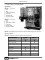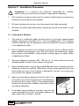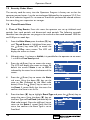
1
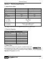
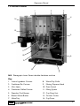
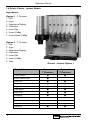
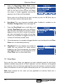
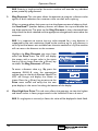
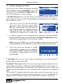
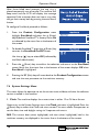
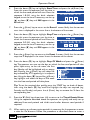
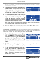
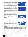
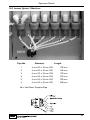
Operators Manual
Part No. PR10350000
New 03/04
Operators Manual
Contents
Page No.
Introduction ...................................................................................................2
Important Safeguards ...................................................................................2
Section 1 - Machine Specifications............................................................3
Section 2 - Installation Procedure ............................................................9
Section 3 - How To Vend A Drink ..........................................................13
Section 4 - Daily Cleaning and Re-filling ...............................................16
Section 5 - Service Keypad Functions ...................................................23
Section 6 - Programming Mode ..............................................................28
Section 7 - Operators Program ..............................................................31
Section 8 - Error Messages & Simple Problem Solving .....................44
Section 9 - Recommended Spare Parts ................................................47
Section 10 - Pipe Lengths .........................................................................52
Section 11 - De-commissioning the Machine ......................................55
The following symbol is used throughout this Operators Manual:
Safety First! Take care, risk of personal injury.
Crane Merchandising Systems accepts no responsibility for damage caused to the equipment through
misinterpretation or misuse of the information contained in this manual.
© Copyright 2004 Crane Merchandising Systems
1
Operators Manual
Introduction
This manual provides a guide to the installation, daily operation, basic cleaning and
maintenance tasks for the Genesis instant and freshbrew table top beverage vending
machines and indicates when the operator should call a qualified service engineer for
assistance. It is recommended that this equipment is serviced by a trained Service
Technician.
It is the policy of Crane Merchandising Systems to continue developing its range of
beverage equipment.The information presented within this document is for information
only and may be changed without prior notice.
Important Safeguards
When using the machine, always have this manual available for quick and easy reference
and always follow these basic safety precautions:
1.
Read all instructions before using the machine and ensure that anyone who will
be involved with the cleaning or refilling of the machine also reads the
instructions.
2.
The machine should be situated on a strong horizontal surface suitable of
supporting 70kg minimum, at a convenient height and in a position where it is not
likely to be knocked off.
3.
The mains lead should never trail from the machine and should always be kept
away from hot surfaces and sharp edges.
4.
Do not operate the machine if any part is damaged, e.g. mains lead, until it has
been checked by a qualified Service Technician.
5.
Allow the machine to cool before handling or moving.
6.
Never immerse the machine in water, or any other liquid and never clean it with
a water jet.
7.
If the machine should accidentally freeze up, call a Service Technician to check it
before switching on.
8.
Ensure that you are conversant with the ‘Health and Safety at Work and Electricity
at Work Regulations 1989’.
ALWAYS DISCONNECT THE MACHINE FROM THE MAINS ELECTRICITY
SUPPLY BEFORE CLEANING AND SERVICING.
This machine is for indoor use only and because it is a beverage machine, should be
sited in a clean, hygienic area.
2
Operators Manual
Section 1 - Machine Specifications
1.1 Specifications Table
Instant
Freshbrew
Height
750 mm
750 mm
Depth
590 mm
590 mm
Width
540 mm
540 mm
Weight
70 kg
70 kg
230
230
7
6
Cup Capacity
Number of Canisters
Electrical Requirements
(i) Voltage
(ii) Current
(iii) Frequency
Water Services
(i) Pressure
(ii) Stopcock
220 - 240V ac
13 Amp fused
50Hz
100 Kpa (1 Bar) - 800 Kpa (8 Bar)
15 mm BSP from rising main
All weights and dimensions are approximate and are for guidance only.
1.2 Canister Capacities
Canister Capacities (Approximate)
Freshbrew Coffee
Freshbrew Tea
Instant Coffee
1.8 kg - 260 cups
0.73 kg - 200 cups
0.67 kg - 420 cups
Instant Tea
0.365 kg - 830 cups
Chocolate
2.25 kg - 130 cups
Milk/Topping
1.4 kg - 180 cups
Soup
2.25 kg - 270 cups
Lemon Tea
2.25 kg - 230 cups
Sugar
2.8 kg - 1075 cups
1.3 Water Filter
Genesis machines fitted with a paperless freshbrew brewer must
be connected to the water supply via a scale inhibiting water filter.
Crane Merchandising Systems recommend and supply the Brita
AquaQuell Compact water filter.
3
Operators Manual
1.4 External Features
1
2
10
3
4
5
9
8
6
7
Key:
1.
Coin Entry
6.
Coin Return
2.
Coin Reject Button
7.
Foot
3.
LCD Display
8.
Door Lock
4.
Drink Selection Keypad
9.
Graphic Panel
5.
Selection Decals
10. Door
4
Operators Manual
1.5 Internal Features
1
2
3
4
14
13
5
12
11
10
6
9
8
7
N.B. Photograph shows Genesis double freshbrew machine
Key:
1.
Instant Ingredient Canister
8.
Waste Tray Grille
2.
Freshbrew Tea Canister
9.
Moving Dispense Head
3.
Main Loom
10. Door Switch
4.
Freshbrew Coffee Canister
11. Mixing System
5.
Paperless Dual Brewer
12. Cup Drop Unit
6.
Brewer Waste Bucket
13. Canister Outlet
7.
Wate Tray
14. Cup Turret
5
Operators Manual
1.6 Drinks Choice - Instant Models
Ingredients:
Option 1 - 7 Canisters
1. Milk
2. Sugar
3. Cappuccino Topping
4. Chocolate
5. Instant Tea
6. Instant Coffee
7. Instant Decaf. Coffee
Option 2 - 7 Canisters
1. Milk
2. Sugar
3. Cappuccino Topping
4. Chocolate
5. Instant Tea
6. Instant Coffee
7. Soup
Genesis - Instant Option 1
Drink Selections
Option 1
7 Canisters
Option 2
7 Canisters
Instant Coffee
●
●
Instant Coffee Decaf.
●
Instant Tea
●
●
Chocolate
●
●
Cappuccino
●
●
Caffe Mocha
●
●
Caffe Latte
●
●
Chocomilk
●
●
Hot Milk Flavour
●
●
Espresso
●
●
●
Soup
Hot Water
6
●
●
Operators Manual
1.7 Drinks Choice - Freshbrew Models
Ingredients:
Option 1 - 6 Canisters
1. Milk
2. Sugar
3. Cappuccino Topping
4. Chocolate
5. Freshbrew Tea
6. Freshbrew Coffee
Option 2 - 6 Canisters
1. Milk
2. Sugar
3. Instant/Decaf. Coffee
4. Chocolate
5. Freshbrew Tea
6. Freshbrew Coffee
Option 1: All speciality drinks made with freshbrew coffee. Cappuccino made with
cappuccino topping.
Option 2: Cappuccino made with coffee, milk and chocolate.
Drink Selections
Freshbrew Coffee
Option 1
6 Canisters
Option 2
6 Canisters
●
●
●
Instant/Decaf. Coffee
Freshbrew Tea
●
●
Chocolate
●
●
Cappuccino
●
●
Caffe Mocha
●
●
Caffe Latte
●
●
Chocomilk
●
●
Hot Milk Flavour
●
Espresso
●
●
Hot Water
●
●
7
Operators Manual
8
Operators Manual
Section 2 - Installation Procedure
Important! It is essential that personnel responsible for installing,
commissioning and servicing the machine understand the following:
1.
The installation and commissioning of the machine should only be carried out by
trained and authorised service engineers.
2.
All water and electrical services must be correctly and safely connected.
3.
All covers should be replaced correctly and securely and the machine left in a safe
condition.
2.1 Locating the Machine
1.
The machine is suitable for indoor use only, sited in an area with a recommended
ambient temperature not below 10º C and not exceeding 30º C. The machine
should be located near the appropriate water and electrical services as detailed
in the specification table.
2.
Prior to moving the machine to its location, ensure that there is sufficient access
space available via passageways, stairs, lifts, etc and that the table/counter where
the machine is to be located is strong enough to safely support its weight. (Refer
to Specifications Table).
3.
To ensure adequate ventilation, 100 - 150 mm (4 - 6 inches) clearance must be
allowed between the back of the cabinet and the wall.
4.
Open the cabinet door using the key provided. Remove all transit packing and the
installation kit from the machine. Check for visual signs of damage which may have
occurred during transit. If the machine is damaged or any parts are missing, you
must contact the supplier immediately.
5.
Referring to the diagram opposite, fit the four feet (1) to
the machine. Ensure that the spacer (2) is fitted between
the washers (3) as shown. Using a 12 mm spanner, adjust
the feet until the machine is levelled in both front to back
and side to side planes.
2
3
1
6.
Fit the door switch bracket to the door using the two
screws provided. Ensure that the bracket operates the
door switch when the door is closed.
9
Operators Manual
2.2 Connecting the Water Supply
1.
The machine should be situated within 1 metre of a drinking water supply from
a rising main, terminating with a W.R.C. approved 15mm compression stop-tap.
2.
The water supply should comply with both the Statutory Instrument No.1147 “Water, England and Wales” and The Water Supply (Water Quality) Regulations
1989.Water pressure at the stop-tap must be within the limits 1 - 8 Bar (100 Kpa 800 Kpa).
3.
Connect the flexi-hose supplied with the machine to the stopcock ensuring that the
seal supplied is fitted correctly. Flush the system (several gallons) before connecting
the machine.
4.
Connect the hose to the inlet valve located on the rear of the machine. Ensure that
the seal is correctly fitted. Ensure that all water supply fittings are tight.
5.
Freshbrew Machines: Genesis machines fitted with the paperless freshbrew
brewer must be connected to the water supply via a water filter.This filter must
be of food grade quality and able to remove temporary hardness (scale), heavy
metals (lead, copper, iron, cadmium), chlorine and any organic
pollutant's/discolouration. Crane Merchandising Systems recommend and supply
the Brita AquaQuell Compact water filter.
Note! If the machine is connected to the water supply
and used without a water filter as specified above, the
warranty will be void.
6.
Turn on the water supply at the stop tap and check for leaks. Prime the water filter
(where fitted) following the instructions supplied by the filter manufacturer.
2.3 Connecting the Electricity Supply
Safety First! The machine must be earthed. On no account should it be
earthed only to the water supply pipe.
The machine must be connected to a 240 Volt 50Hz 13 amp fused switched socket
outlet, installed to the latest edition of the IEE regulations, using a 3 pin BS approved
13 amp fused plug.
Important: If the mains lead becomes damaged in any way it must be replaced by a
special lead available from the manufacturer.
10
Operators Manual
2.4 Commissioning Procedure
The following procedure must be carried out by a trained installation engineer before
the machine can be used for the first time.
1.
Ensure that the electrical and water services to the machine are connected
correctly and turned on. Ensure that the waste tray is fitted correctly to the
machine. Open the front door of the machine and swing the cup turret assembly
out of the machine.
2.
Rotate canister outlets to upright position and remove the ingredient canisters DO NOT place ingredient canisters on the floor. Remove the lids from the
ingredient canisters.
Fill the canisters with the correct ingredients, re-fit the lids and re-fit canisters into
machine ensuring that they are returned to their correct positions. Rotate the
canister outlets to their correct operating positions.
Freshbrew Models: Fill freshbrew ingredient canisters with freshbrew tea and
coffee ingredient and refit to machine.
3.
Load the cup turret. Fill the tubes with the correct
size cups for the type of cup catcher fitted to the
machine. Allow the cups to drop into the tubes
directly from the packaging. DO NOT TOUCH
THE CUPS WITH YOUR HANDS.
Important: Do not fill the tube directly above the
cup dispense position. Allow the cup turret motor
to rotate a full tube to the cup dispense position.
Rotating the cup turret by hand will damage the
mechanism.
Note: If paper cups are being loaded, each pack of cups must first be inspected
for damage to the cup rims. Damaged cups must not be used.
4.
Swing the cup turret assembly back to its operating position. Ensure that the unit
is held securely by the magnetic catch.
5.
Insert the safety key (a) supplied with the machine into the
door switch as shown.The machine is now on.The water
inlet valve will open and the heater tank will start to fill.
The cup turret mechanism will index the first available full
cup stack to the dispense position and drop the cup stack
into the cup drop mechanism. Fill the remaining empty cup
stack with cups.
a
11
Operators Manual
6.
While the machine is powering up, the LCD will
display the message as shown opposite. As the
water heats, ensure that no water overflows
from the heater tank overflow pipe into the
waste tray. Check the system for leaks.
Important: Should the machine fail to fill correctly or leak, turn off the
stopcock and the power to the machine before investigating the fault.
7.
Check the LCD display on the front of the machine to ensure that the water has
heated to the correct temperature and that the machine is in standby mode. A
machine set to free vend mode will alternate the messages:
N.B. Messages displayed in standby mode will change depending upon the
monetary device fitted and set up during programming.
8.
Ensure that the cup drop mechanism operates correctly. Press the Cup Test
switch (7), located in the Service Keypad on the rear of the door (see page 27)
and ensure that a cup is ejected cleanly from the cup drop unit.
9.
Freshbrew Models: Ensure the brewer guard and brewer waste container are
fitted correctly. Slide the container into position directly under the brewer with
its lip outside the brewer cover.
10. If fitted, check that the coin mechanism and cash box operate correctly. Fill the
coin tubes with correct coinage. Ensure coin return mechanism functions
correctly.
11. Operate the machine through its complete range of selections to ensure that each
vend is correctly dispensed. Follow the instructions detailed on page 26 for making
a vend using the Test Vend switch (6) located on the Service Keypad.
12. Remove the safety key and close the cabinet door. Ensure that the machine is left
in a clean and safe condition.
12
Operators Manual
Section 3 - How to Vend A Drink
3.1 Selecting A Drink
Drink selections are made by pressing the appropriate selection button on the keypad
and then utilising the keypad selection buttons and the LCD display to alter the drink
strength and add milk/sugar to suit the customers personal preference.
The following example shows an instant coffee selection from an instant machine set
to ‘Free Vend’.
1. Press selection button 1, Instant Coffee on the
keypad.The machine exits the standby mode and
the LCD will display the screen as shown
opposite. The default strength setting for this
drink selection is Normal as shown.
2. To obtain a Strong or Mild beverage it is necessary to press the current drink
selection button. Pressing once will toggle to the Strong selection. Pressing the
button again will toggle to the Mild selection.
Pressing the current drink selection button again will revert to the default screen.
3. If milk and/or sugar is required, it is necessary to
press the corresponding button on the keypad
for each selection. When the Milk button is
pressed the LCD changes and displays the
default screen as shown opposite.
4. If Extra Milk is required the customer presses the milk button a second time. A
third press will display the No Milk selection.
13
Operators Manual
Pressing the milk button again will revert to the default milk selection.
5. If the customer requires sugar it is necessary to
press the sugar button. The LCD changes and
displays the default screen shown opposite.
6. If Extra Sugar is required the customer presses the sugar button a second time.
A third press will display the No Sugar selection.
Pressing the sugar button again will revert to the default sugar selection.
7. Once the required drink has been selected, press the Start button on the keypad.
Unless the customer has placed their own cup
into the dispense area, a cup will automatically be
ejected from the cup drop unit into the dispense
area and the drink selection will be delivered into
the cup.Whilst this operation is in progress the
LCD will display the screen shown opposite.
8. After the beverage has been dispensed the LCD
will display the message Thank You and the
machine will beep once before returning to
standby mode.
The drink can then be carefully removed from
the dispense area.
9. Certain drink selections do not allow the
strength option to be selected or milk added. For
example, if the customer presses the
Cappuccino selection button the LCD will
display the screen opposite. The customer can
either press the start button to vend the drink
or press the sugar button in order to add sugar to their taste as described above.
14
Operators Manual
10. Other drink choices do not allow the strength
option or milk/sugar to be selected. For
example, if the customer presses the
Chocolate selection button the LCD will
display the screen opposite.
The customer simply presses the start button and the machine will vend their
drink.
15
Operators Manual
Section 4 - Daily Cleaning and Re-filling
The quality of drinks produced by the Genesis can only be maintained if the machine
is cleaned regularly following the schedule outlined. Before carrying out the daily
cleaning procedure described on the following pages, it is recommended that you have
the following materials to hand:
❍ Bactericidal Cleaner
❍ De-Staining Agent
❍ Cleaning Cloths
❍ Paper Towels
❍ Small Brush
❍ Two Large Buckets
❍ Disposable Gloves
4.1 Bactericidal Cleaner
This can either be a liquid or powder agent which should be dissolved in clean water
in accordance with the instructions on the product packaging. The solution should be
used for cleaning machine components and wiping surfaces during the cleaning
operation.
4.2 De-Staining Agent
This is a liquid or powder agent which should be dissolved in clean water in accordance
with the instructions on the product packaging. The solution can be used on heavily
soiled or stained components such as buckets and drip trays. Items or surfaces cleaned
with this solution must be rinsed in clean water to remove traces of the cleaning agent.
4.3 Liquid Destainer - Brewer Units
Crane Merchandising Systems recommends that a liquid destaining product is used for
cleaning the brewer unit fitted to Genesis freshbrew machines.The product must be
used in accordance with the instructions on the product packaging, following all health
and safety guidelines. A detailed procedure for cleaning the brewer unit is outlined on
page 21 of this Operators Manual.
It is necessary to carry out the cleaning and maintenance procedure outlined on the
following pages on a regular basis, either at the end of the day or at the start of the
day before the machine is in constant use.
16
Operators Manual
4.4 Cleaning & Filling Procedure - All Machines
1.
Fill a cleaning bucket with hot water and dilute the
bactericidal cleaner in accordance with the
instructions on the product packaging.
Open the door of the machine. Swing the cup
turret assembly out of the machine in order to gain
access to the ingredient canisters.
2.
Rotate canister outlets to upright position. Remove
the ingredient canisters. DO NOT PLACE THEM
ON THE FLOOR.
With a clean, damp sanitised cloth, remove any
ingredient build up on the exterior of the canisters,
paying particular attention to the area around the
canister outlets.
3.
Remove the dispense pipes (a) from the mixer units
(b) and the plastic dispense block.
c
Remove steam hoods (c) from mixer units. Twist
the whipper base (d) anti-clockwise until it clicks.
d
b
a
4.
Remove mixer units (a) and impellers (b).Twist the
whipper base (c) anti-clockwise until it releases. Pull
the whipper base off of the shaft.
b
Clean all of the mixing system parts, including the
steam hoods and dispense pipes thoroughly in the
diluted bactericidal cleaner solution.
Rinse all components with clean water and dry
thoroughly before refitting to machine.
c
a
17
Operators Manual
5.
Remove the knurled nut securing the plastic
dispense block to the dispense head assembly.
Remove the dispense block and clean thoroughly in
the diluted bactericidal cleaner solution.
Rinse the dispense block with clean water and dry
thoroughly before refitting to machine.
6.
Refit the whipper base. Push the whipper base onto
the motor shaft with the ‘arrow’ symbol lined up
with the motor plate fixing screw (a) as shown.
a
b
Rotate the whipper base clockwise until it locates
with the first locking position (b). Ensure ‘O’ ring (c)
is correctly located as shown.
Refit the impellers to motor shafts ensuring that
the ‘flat’ in the moulding (identified with an arrow
symbol) lines up with the flat on the shaft.
7.
Refit mixer units as shown. Rotate the whipper
base clockwise until it locks into place
Refit steam hoods and dispense pipes to mixer
units.
Refit the dispense pipes to the dispense block.
Important: Ensure pipes are refitted to their
correct outlet position on the dispense block (see
pages 51 - 53 for details).
8.
Check the ingredient canisters and refill if required.
Refit the canisters into the machine from left to
right turning the outlets to their correct positions.
Important: Ensure that the canisters are refitted
correctly.
Weekly: Empty and wash the ingredient canisters.
Dry thoroughly, refill and refit into machine.
18
c
Operators Manual
9.
Undo the thumb screws and remove cup catcher
complete with drain pipe (a).
Clean cup catcher and pipe in the sanitiser solution.
Rinse components with clean water and dry
thoroughly.
Reassemble to machine ensuring that drain pipe is
correctly located.
a
10. Carefully remove the waste tray from the machine.
Remove the waste tray grille and empty the
contents of the tray. Wash the tray and grille
thoroughly and where necessary, sanitise using the
diluted bactericidal cleaner solution.
Dry both components using a clean, dry cloth.
Reassemble the waste tray and grille and refit to the
machine.
11. Check the levels of the cups in the cup stack.
Where necessary, refill with correct sized cups.
DO NOT TOUCH THE CUPS WITH YOUR
HANDS.Allow the cups to drop into the cup stack
directly from the packaging.
Important: Do not fill the tube directly above the
cup dispense position. Allow the cup turret motor
to rotate a full tube to the cup dispense position.
Rotating the cup turret by hand will damage the
mechanism.
Note: If paper cups are being loaded, each pack of cups must first be inspected
for damage to the cup rims. Damaged cups must not be used.
Rotate the cup turret assembly back to its operating position. Ensure that the unit
‘locks’ into place.
19
Operators Manual
12. Un-lock the cashbox (if fitted) located on the rear
of the door and remove from the machine. Remove
any coinage from the cashbox.
Refit the cashbox to the machine, turning the lock
to secure.
Open the coin mechanism cover and wipe the
inside with a damp cloth.
Check the coin tubes and refill if required.
13. Insert the safety key supplied with the machine into
the door switch.The machine is now on.
Using the service keypad located in the rear of the
door (see page 24), proceed as follows:
a.
Press the Cup Test switch (7) and check that
a cup is ejected correctly from the Cup drop
unit.
b. Press the Park Head switch (8) to ensure that
the dispense head operates correctly and that
the dispense pipes are fitted correctly.
c. Place a water tight container under the dispense head and press the
Rinse/Flush switch (3). The machine will flush the system. Check that all of
the mixing stations are water tight. Empty the contents of the container.
d. Place an empty cup under the dispense head. Press the Test Vend switch (6)
and using the selection buttons on the front of the machine, vend a drink to
ensure that the machine operates correctly. Press the ‘X’ (Exit) key to exit
from the Test Vend menu.
e. Press the View Counters switch (5) and record the audit information
displayed on the LCD (see page 25 for full details).
Remove the safety key and close the door. Clean and buff the outside of the
machine.
20
Operators Manual
4.5 Paperless Brewer Unit - Cleaning Procedure
1.
Switch on the power using the door switch safety
key. Press the Brewer Open switch (2) located in
the service keypad on the rear of the door. The
brewer chamber will index to its fully open
position and stop.
Remove the door switch safety key to switch off
the power to the machine. Remove the brewer
guard.
2.
Dual Brewer: Carefully remove the water outlet
tube c/w water pipe (a) from the tea chamber.
Lift the latch bar (b) and remove the brewer
chamber/wipe arms assembly.
a
b
Clean the brewer chamber/wipe arms assembly in
the sanitiser solution. Rinse with clean water and
dry thoroughly.
3.
Carefully slide the brewer chamber(s) into the
brewer unit.
Important: The wiper arm lug (a) must be located
between the stainless steel arms (b) as shown.
b
a
b
4.
Dual Brewer: Re-assemble the water outlet tube
to the tea brewer chamber.
Using the clamp supplied, close the tea outlet tube
as shown.
21
Operators Manual
5.
Switch on the power using the door switch safety
key.The brewer chamber will automatically index to
its closed position.
Ensure that a water tight container is placed under
the dispense area.
Pour the recommended amount of destaining fluid
directly into the top of both brewer chambers.
6.
Dual Brewer: Remove the clamp from tea
dispense pipe.
Press the Brewer Clean switch (4) located in the
service keypad on the rear of the door. The
machine will automatically flush through the
brewer four times.
7.
Remove the door switch safety key. Remove and
empty the water waste container. Refit the brewer
guard.
Remove the brewer waste container from the
machine as shown. Empty the contents.
Wash the waste container thoroughly and where
necessary sanitise using the sanitiser solution. Dry
using a clean cloth and refit into the machine.
Close and lock the door.
22
Operators Manual
Section 5 - Service Keypad Functions
Genesis machines are fitted with a service keypad (a)
mounted on the rear of the door.This keypad contains the
Operators Program entry key and also allows the
operator to carry out specific functions during routine
cleaning and maintenance.
N.B. During certain operations e.g. View Counters it is
a
necessary for the operator to utilise the selection keypad
and LCD mounted on the front of the door to access data.
Please refer to Section 6 - Programming Mode for details of selection keypad layout
and functions.
When the safety key is inserted into the door switch and the machine is switched on,
the service keypad allows the operator to carry out the following functions:
5.1 Switch 1 - Program Entry
This switch allows the operator to access the Operators Program (Section 7, page 31).
5.2 Switch 2 - Brewer Open (Freshbrew Models)
1.
This switch operates the brewer fitted to freshbrew machines and allows the
operator to remove the brewer chamber(s) for cleaning purposes (see page 21
for details).
2.
When the Brewer Open switch (2) is pressed and released, the brewer will
index to its fully open position and stop.The operator can then safely lift the latch
and carry out the cleaning procedure. Pressing and releasing the switch again will
cause the brewer chamber(s) assembly to return to its closed position.
5.3 Switch 3 - Rinse/Flush
1.
The flush sequence operates automatically and rinses the mixing bowls. Before
the sequence begins, the system waits until the water in the boiler is at the
correct temperature determined by the thermistor.
2.
In order to guarantee the highest standards of cleanliness, the boiler fill valve is
disabled, ensuring that the water used in the sequence is delivered at the optimum
temperature to kill any micro-organisms. Each hot water valve and the
corresponding whipper is switched on in sequence for a pre-set flush time.
3.
Once the flush cycle is complete, the boiler refills and when the water is at the
correct temperature, the machine returns to standby mode, ready to vend.
23
Operators Manual
4.
To flush the machine:
a.
Open the front door of the machine and insert the safety key.
Caution: Ensure that a water tight container is placed under the dispense
position. Keep hands away from the dispense area whilst the flushing cycle
is in operation.
b.
Press and release the Flush switch (3).The flush sequence begins.
c.
Empty the waste water container when complete.
5.4 Switch 4 - Brewer Clean (Freshbrew Models)
1.
The brewer flush switch allows the brewer to be flushed independently. In order
to guarantee the highest standards of cleanliness, the boiler fill valve is disabled,
ensuring that the water used is delivered at the optimum temperature to kill any
micro-organisms.
2.
The brewer unit is filled with hot water and then operated through four complete
brew cycles.
3.
Once the flush cycle is complete, the boiler refills and when the water is at the
correct temperature, the machine returns to standby mode, ready to vend.
4.
To flush the brewer:
a.
Open the front door of the machine and insert the safety key.
Caution: Ensure that a water tight container is placed under the dispense
position. Keep hands away from the dispense area whilst the flushing cycle
is in operation.
b.
Pour the recommended amount of destaining fluid directly into the top of
both brewer chambers.
c.
Press and release the Brewer Flush
switch (4). The sequence will begin and
the LCD will display the messages:
d.
Empty the waste water container when
complete.
5.5 Switch 5 - View Counters
Internal counters within the machine software monitor audit data for each individual
drink type along with the total audit data for the machine. When accessed via this
switch, these counters can be viewed by the operator but cannot be reset.
24
Operators Manual
To view the data:
1.
Open the front door of the machine and insert the safety key.
2.
Press and release the View Counters switch
(5). The LCD will display the Resettable
Sales Data screen as shown opposite. From
this menu the operator can view data for the
‘Overall Totals’ (highlighted) or ‘By Product’.
3.
To view the Overall Totals screen, press the ↵ (Enter) key on the drink
selection keypad.This menu displays both the
total £ amount and total vend count (since
the counters were last reset) for the
following data:
● Sales
● Discount
● Test Vend
● Surcharge
● Free Vend
For example:
Sales-£
Sales-#
Discount-£
Discount-#
Test Vend-£
Test Vend-#
Surcharge-£
Surcharge-#
Free Vend-£
Free Vend-#
Displays
Displays
includes
Displays
Displays
Displays
Displays
Displays
Displays
Displays
Displays
the total machine sales in £ - p
the total number of machine vends. This value
normal plus discount and surcharge vend totals)
the total monetary value of all discounts in £
the total number of discounted vends
the total monetary value of all test vends in £
the total number of test vends
the total monetary value of all surcharges in £
the total number of surcharge vends
the total monetary value of all free vends in £
the total number of free vends
4.
Scroll through the list displayed using the up (▲) and down (▼) keys on the
front panel and log the audit data. When complete, press the ‘X’ (Exit) key on
the drink selection keypad to return to the Resettable Sales Data menu
screen.
5.
The operator can also view and log audit data by individual product. Press the
down (▼) key on the drink selection keypad to highlight By Product on the
Resettable Sales Data menu screen.
25
Operators Manual
6.
Press the ↵ (Enter) key on the keypad to enter the By Product menu screen.
This menu contains all of the drink selections available from the machine. Use the
up (▲) and down (▼) keys on the drink selection keypad to scroll through the
menu until the required selection is highlighted.
7.
Press the ↵ (Enter) key on the keypad to enter
the highlighted selection e.g. chocolate. The
LCD will display the screen as shown opposite.
This menu displays both the total £ amount
and total vend count as previously described.
N.B. Individual By Product screens also
display the price set for the selection as
shown.
The operator can then scroll through the list displayed using the up (▲) and
down (▼) keys on the drink selection keypad and log the audit data.
8.
When complete, press the ‘X’ (Exit) key on the drink selection keypad to return
the machine to the previous screen. The operator can then access further
selections using the procedure described above.
9.
To return the machine to standby mode, press the ‘X’ (Exit) key repeatedly until
the LCD displays the standby screen.
N.B. In order to view and then clear data from the Resettable Sales Data menu,
it is necessary for the operator to access the menu via the Operators Program.
5.6 Switch 6 - Test Vend
The Test Vend switch allows the operator to vend a drink from the machine to ensure
correct operation after cleaning or maintenance.
1.
When the switch is pressed and released the
LCD will display the screen as shown opposite.
The operator then presses a drink selection
button followed by the ‘Start’ button to start
the vend sequence.
2.
Ensure that the selection is correct, has not under/overfilled the cup and most
importantly, tastes good!
3.
Press the ‘X’ (Exit) key on the drink selection keypad to exit from the Test menu
and return to stand-by mode.
26
Operators Manual
5.7 Switch 7 - Cup Test
This switch allows the operator to test the operation of the cup drop unit after refilling
the cup stacks. When the switch is pressed the cup drop solenoid is operated and a
cup is ejected from the cup drop unit. This function ensures that the mechanism is
working correctly.
5.8 Switch 8 - Park Head
When this switch is pressed, the dispense head moves to its fully extended position
and stops. Press the switch again to return the dispense head to its correct (homed)
position.
N.B. It is necessary for the operator to wait for a few seconds between each key press
to allow the machine to respond accordingly.
27
Operators Manual
Section 6 - Programming Mode
6.1 Drink Selection Keypad
Programming mode utilises the drink selection keypad, as defined in the illustration
below, and allows the operator to view and alter stored data within the machines
memory. During programming the keys are used as follows:
Keys 0-9
Used for entering numerical data
▲
For indexing up in a program, or
incrementing data
▼
For indexing down in a program, or
incrementing data
↵
(Edit/Enter) Used to select and enter
the highlighted menu and to save data
to machines memory
X
(Exit) To return to the previous menu
screen
START
Press to ‘set all’ or ‘clear all’ data or
begin a test sequence.
MILK
START
SUGAR
Note: The START button can also be used to access a help menu during certain
programming operations.
6.2 Menu Display
The Genesis features our new interactive menu display. The multi line LCD display
helps to make navigating the programming menu structure easy and intuitive. It is used
to display programming information and will change according to the type of data being
updated.
1.
The top line of the screen is the Menu title.
2.
Selected items are highlighted in white. Press
the up (▲) or down (▼) keys on the drink
selection keypad to highlight an item.
3.
Press the ↵ (Enter) key to select the item. In this example, pressing the the ↵
(Enter) key will display the Mug Discount screen.
4.
The bottom line of the screen will often show important information. In certain
28
Operators Manual
configuration menus it will display the current value for the selected item. In the
example shown the screen is showing that the current Mug Discount is set at
0.05p.This is a useful way to quickly check stored settings and also confirm that
a value has been altered correctly.
5.
To return to the Main Menu from any screen, simply press the ‘X’ (Exit) key
until you reach the Main Menu.
6.3 Accessing the Programming Mode
1.
Open the front door of the machine and insert the safety key to restore power
to the machine.The machine is now on.
2.
Press the Program Entry key (1) on the
service keypad, located inside the door (see
page 24 for details). The LCD will display the
screen as shown opposite. Enter the 4 digit
operators entry pin code using the drink
selection keypad.
N.B. The factory default code is entered by pressing the sequence 2-2-2-2.You
may be issued with your own personalised code.
4.
Press the ↵ (Enter) key. Providing the
operator has entered the code correctly, the
LCD will display the screen as shown opposite.
Press the ↵ (Enter) key to access the
operators program or ‘X’ (Exit) key to return
the machine to standby mode
5.
The LCD on the front of the machine will
display the top level programming menu screen
- Main Menu. The first available menu Data
Recall is highlighted indicating that it can be
selected.To move to a different menu press the
up (▲) or down (▼) keys on the drink
selection keypad until the required menu is
highlighted.
6.
With the required menu highlighted, press the
↵ (Enter) key to select it. Using the Price
menu as an example, the LCD will display the
sub menus as shown opposite.
29
Operators Manual
7.
Using the up (▲) or down (▼) keys, the ↵ (Enter) key and the ‘X’ (Exit) key it
is possible to easily navigate through all of the menus contained within the
Operators Program.
8.
To update parameters, key in the actual digits of the number required using the
selection keys 0-9. Once the correct parameter has been entered, press the ↵
(Enter) key to overwrite the previous value and save the new parameter in the
machines memory. Pressing the ‘X’ (Exit) key will move back to the previous
screen.
Certain programming functions require that the operator chooses either one or
multiple parameters within a sub program. These can take the form of either check
boxes or radio buttons.
10.
Check Boxes: The example opposite shows
the Days of Week screen accessed via the
Sanitation Events Menu which allows the
operator to choose multiple days of the week
on which a specific function will take place.
11.
Using the up (▲) or down (▼) keys, scroll through until the required day is
highlighted as shown. Pressing the ↵ (Enter) key will select the day, indicated by
an X appearing in its adjacent box.
Continue until all required days have been selected. Pressing the ‘X’ (Exit) key will
move back to the previous screen and save the new settings to the machines
memory.
N.B. Pressing the START key on the drink selection keypad will check all boxes
if empty or clear all boxes if checked.
12.
Radio Buttons: The example opposite shows
the State screen accessed via the Timed
Events Menu which requires the operator to
select one of the options shown. Use the up
(▲) or down (▼) keys to set the required
option followed by the ↵ (Enter) key to
store/save it (indicated by the filled radio
button).
All operator programming for the Genesis range follows the procedures as described
above. Specific program actions are described fully in the following section.
30
Operators Manual
Section 7 - Operators Program
To access the Operators Program, enter the
programming mode as described in section 6. Once
in the Operators Program the LCD on the front of
the machine will display the top level programming
menu screen - Main Menu. There are six top level
menu items as shown opposite.
Using the up (▲) and down (▼) keys, ↵ (Enter) key and ‘X’ (Exit) key on the drink
selection keypad the operator can navigate quickly and easily through the operators
program menus as described in section 6.
7.1 Data Recall Menu
Entry into this menu allows the operator to view Non-Resettable and Resettable Sales
Data, view data relating to the number of Mug Vends
and (if feature enabled) view SureVend™ assisted
vend information. The Resettable Sales Data, Mug
Data and SureVend™ Data menus all contain an
extra menu which allows the engineer to delete the
current data from the machines memory.
1.
Non Resettable Sales Data: This menu allows the operator to view and
record monetary and sales values.This data cannot be reset and will remain intact
for the service life of the controller board.
1.
From the Data Recall screen highlight Non
Resettable Sales Data and press the ↵
(Enter) key.The LCD will display the screen as
shown opposite. From this menu the operator
can view data for the Overall Totals
(highlighted) or By Product.
2.
To view the Overall Totals screen, press the
↵ (Enter) key on the drink selection keypad.
This menu displays both the total £ amount
and total vend counts for the following data:
● Sales
● Discount
● Test Vend
● Surcharge
● Free Vend
31
Operators Manual
For example:
Sales-£
Sales-#
Discount-£
Discount-#
Test Vend-£
Test Vend-#
Surcharge-£
Surcharge-#
Free Vend-£
Free Vend-#
Displays
Displays
includes
Displays
Displays
Displays
Displays
Displays
Displays
Displays
Displays
the total machine sales in £ - p
the total number of machine vends. This value
normal, discount and surcharge vend totals.
the total monetary value of all discounts in £
the total number of discounted vends
the total monetary value of all test vends in £
the total number of test vends
the total monetary value of all surcharges in £
the total number of surcharge vends
the total monetary value of all free vends in £
the total number of free vends
3.
Scroll through the list displayed using the up (▲) and down (▼) keys on the
front panel and log the audit data. When complete, press the ‘X’ (Exit) key on
the drink selection keypad to return to the Non Resettable Sales Data menu
screen.
4.
The operator can also view and log audit data by individual product. Press the
down (▼) key on the drink selection keypad to highlight By Product on the
Non Resettable Sales Data menu screen.
5.
Press the ↵ (Enter) key on the keypad to enter the By Product menu screen.
This menu contains all of the drink selections available from the machine. Use the
up (▲) and down (▼) keys on the drink selection keypad to scroll through the
menu until the required selection is highlighted.
6.
Press the ↵ (Enter) key on the keypad to enter
the highlighted selection e.g. chocolate. The
LCD will display the screen as shown opposite.
This menu displays both the total £ amount
and total vend count as previously described.
N.B. Individual By Product screens also
display the price set for the selection as
shown.
The operator can then scroll through the list displayed using the up (▲) and
down (▼) keys on the drink selection keypad and log the audit data.
7.
32
When complete, press the ‘X’ (Exit) key on the drink selection keypad to return
the machine to the previous screen. The operator can then access further
selections using the procedure described above.
Operators Manual
8.
To return the machine to standby mode, press the ‘X’ (Exit) key repeatedly until
the LCD displays the standby screen.
2.
Resettable Sales Data: This menu contains similar data to the Non Resettable
Sales Data menu and allows the operator to view and record monetary and vend
counts. However, once viewed and recorded, data from this menu can be cleared
from the machines memory.
1.
From the Data Recall screen, highlight Resettable Sales Data and press the
↵ (Enter) key. The LCD will display the screen
as shown opposite. From this menu the
operator can view data for Overall Totals
(highlighted) or By Product. The menu also
allows the operator to delete all resettable
data via the Clear Data menu.
2.
To view the Overall Totals screen, press the
↵ (Enter) key on the drink selection keypad.
This menu displays both the total £ amount
and total vend count (since the last time it
was cleared) for the following data:
● Sales
● Discount
● Test Vend
● Surcharge
● Free Vend
N. B. Please see page 32 for detailed descriptions of these data fields.
3.
Scroll through the list displayed using the up (▲) and down (▼) keys on the
front panel and log the audit data. When complete, press the ‘X’ (Exit) key on
the drink selection keypad to return to the Resettable Sales Data menu
screen.
4.
The operator can also view and log resettable monetary and vend data by
individual product. Press the down (▼) key on the drink selection keypad to
highlight By Product on the Resettable Sales Data menu screen. Follow the
procedure as described previously to view data for individual drink selections.
5.
Once the operator has viewed and recorded required information from the
Resettable Sales Data menu, this data can be deleted via the Clear Data sub
menu.
33
Operators Manual
6.
From the Resettable Sales Data screen,
highlight the Clear Data sub menu using the
down (▼) key and press the ↵ (Enter) key. The
LCD on the front of the machine will display
the screen as shown opposite, warning the
operator that all data will be deleted.
Either press the ↵ (Enter) key to clear the data or press the ‘X’ (Exit) key to
exit the menu without clearing the data.
3.
SureVend: This menu becomes available when SureVend is enabled via the
Product Configuration menu (see page 37).
1.
From the Data Recall menu scroll down and
highlight SureVend then press the ↵ (Enter)
key. The LCD will display the screen as shown
opposite. From this menu screen the engineer
can view and record the number of cup drop
failures that SureVend has logged and also the
number of SureVend assisted vends.
2.
Once the operator has viewed and logged the data it can be cleared via the Clear
Data menu as described previously.
4.
Mug Vends: This menu displays the number of
vends that the machine has made without
dropping a cup. Once the operator has viewed
and logged the data it can be cleared via the
Clear Data menu as described above.
7.2 Price Menu
Entry into this menu allows the operator to enter individual prices for each drink
selection available, one price for all drink selections and set a discount to be applied
for customers who use their own cup/mug.The menu also contains a sub menu which
allows the operator to view the highest and lowest price set in the machines memory.
N.B. Values entered via this menu are only applicable to machines fitted with a
coin/card system.
34
Operators Manual
1.
Individual Prices: This sub menu allows the
engineer to set an individual price for each drink
selection available from the machine. With
Individual Prices highlighted as shown
opposite, press the ↵ (Enter) key to access the
menu.
Upon entry into this sub menu, all drink
selections available from the machine are listed
along with the current drink price for the
highlighted selection. The example shown
illustrates an Instant Coffee selection with a price
set currently at 35p.
To change the price of the highlighted
selection, press the ↵ (Enter) key.The LCD will
change and display the screen as shown. To
update the price, e.g. increase to 45p, press the
sequence 0-0-0-4-5 using the appropriate
number keys on the drink selection keypad.
Press the ↵ (Enter) key to return to the Individual Prices screen and verify that
the new price displays in the status line along the bottom of the display. Use the
up (▲) or down (▼) keys to highlight further selections.
2.
Entire Machine: This sub menu allows the
operator to set a single price for all selections
available from the machine. When highlighted
from within the Price menu, the LCD will
display the screen, with the current value in the
status line (e.g. 40p), as shown.
Tip: If most selections are to be sold at the same price, use this menu to quickly
set the entire machine to this price, then go to Individual Prices (page 34) to
adjust prices for individual selections.
Press the ↵ (Enter) key to access the Entire
Machine sub menu. To update the value, e.g.
set a price of 50p, press the sequence 0-0-0-50 using the appropriate number keys on the
drink selection keypad. Press the ↵ (Enter) key
to return to the Price menu screen and verify
that the new price displays in the status line along the bottom of the display.
35
Operators Manual
N.B. Entering a single price for the entire machine will override any individual
prices previously programmed.
3.
Mug Discount: This sub menu allows the operator to program a discount value
against all drink selections for customers who use their own cup/mug.
When a customer places their own cup into the dispense area and selects a drink,
the SureVend™ product delivery sensors will detect the cup and disable the
cup drop mechanism.The price set for Mug Discount is then subtracted from
the price of the drink selected and the appropriate change/credit returned to the
customer.
N.B. It is important to ensure that any value entered for a mug discount is
supported by the coin mechanism fitted to the machine, eg if a mug discount is
set at 2p but the lowest coin available from the coin mechanism is 5p, the machine
will not return the discount to the customer.
Highlight the Mug Discount sub menu from
within the Price menu. The LCD will display
the screen, with a current value in the status
line (e.g. 5p), as shown. Press the ↵ (Enter) key
to access the Mug Discount sub menu.
To enter a discount value, e.g. 10p, press the
sequence 0-0-0-1-0 using the appropriate
number keys on the drink selection keypad.The
LCD will change and display the screen as
shown. Press the ↵ (Enter) key to return to the
Price menu screen and verify that the new
price displays in the status line along the bottom of the display.
4.
View High/Low Price: This sub menu allows the operator to view the highest
and lowest values in force, programmed via the Individual Prices sub menu.
N.B. If a single price is currently in force, this value will be displayed in both fields.
36
Operators Manual
7.3 Product Configuration Menu
Entry into this menu allows the operator to disable
drink selections and turn SureVend™ on or off.
Upon entry into the Product Configuration menu
the LCD will display the screen as shown.
1. Disable Selections: This sub menu allows the operator to disable individual or all
drink selections if necessary. With Disable Selections highlighted, press the ↵ (Enter)
key to access the menu.
1.
Upon entry into the menu the LCD will display
the screen as shown. Using the up (▲) or down
(▼) keys, scroll through the menu until the
required drink selection is highlighted. Pressing
the ↵ (Enter) key will select the drink,
indicated by an X appearing in its adjacent box.
2.
If necessary continue until all required drink selections have been checked.
Pressing the ‘X’ (Exit) key will move back to the Product Configuration screen
and save the new parameters to the machines memory.
N.B. Pressing the START key on the drink selection keypad will check all boxes
if empty, disabling all drink selections or clear all boxes if previously checked.
3.
Once the machine has returned to standby
mode, should a customer press for a selection
that has been disabled, the machine will display
the following screen before returning to
standby mode.
2. SureVend: Entry into this menu allows the operator to turn the SureVend™
product delivery sensor on or off.
SureVend™ Overview: SureVend™ ensures that a cup is always available in the cup
station before any money is collected or product delivered. The sensing system is a
beam of infra-red light across the cup station that is broken by a cup as it falls into
position from the cup drop unit, or by a customers own mug placed in the dispense
area.
The SureVend™ software monitors the cup station sensor during the time that the
cup ring is operated and for three seconds afterwards. If a cup is not detected the
software will then attempt to drop a cup a second and if necessary, a third time.
37
Operators Manual
After three failed vend attempts the cup ring is
placed temporarily out of service. The machine will
beep once and the LCD will display the message
opposite. If the customer does not have a mug, they
can get their money back by pressing the coin return
button.
To configure SureVend, proceed as follows:
1.
From the Product Configuration menu
highlight SureVend and press the ↵ (Enter)
key. By default SureVend™ is factory set to On
as indicated by the status line at the bottom of
the screen.
2.
To disable SureVend™, press the ↵ (Enter) key
to enter the SureVend On/Off screen.
Use the up (▲) key to select Off (indicated by
the filled radio button).
3.
Press the ↵ (Enter) key to confirm the selection and return to the SureVend
screen.Verify that the status line at the bottom of the screen displays Off when
SureVend is highlighted.
4.
Pressing the ‘X’ (Exit) key will move back to the Product Configuration screen
and save the new parameter to the machines memory.
7.4 System Settings Menu
This menu allows the operator to set the current time and date, and view the software
version installed in the machine.
1. Clock: The machine displays the current time in either 12 or 24 hour format.
Upon entry to the System Settings menu, the Clock sub menu is highlighted. Press the
↵ (Enter) key to access the Clock sub menu screen.This menu allows the operator to
set the date, time and daylight saving via 3 separate sub menus.
N.B. The current date (when highlighted) and time (when highlighted) held in the
machines memory are displayed in the status line at the bottom of the screen.
38
Operators Manual
1.
Date: Press the ↵ (Enter) key to enter the
Date menu.The date is displayed in day, month,
year format. To set the date, e.g. 27th January
2004, press the sequence 2-7-0-1-0-4 using the
appropriate number keys on the drink selection
keypad.
N.B. The text ‘Press 0-9 to Edit Value’ displayed in the status line at the bottom
of the screen will alternate with the text ‘Press Start To Change Mode’. Pressing
the START button on the drink selection keypad allows the date to be displayed
in month, day, year format.
Pressing the ↵ (Enter) key will move back to the Clock menu screen and save
the date to the machines memory. Confirm that the status line at the bottom of
the screen displays the correct date when Date is highlighted.
2.
Time: From the Clock menu screen press the down (▼) key to highlight the
Time menu followed by the ↵ (Enter) key.The
LCD will display the screen as shown opposite.
By default the time is displayed in 12 hour
format. To enter a time of 10:30 PM press the
sequence 1-0-3-0 on the drink selection
keypad.
As the operator presses the final zero, the AM
value will appear within a dotted box and the
text at the bottom of the LCD will now read
“Press Arrows To Select”. Press the up (▲) or
down (▼) key until PM appears in the box.
Pressing the ↵ (Enter) key will move back to the Clock menu screen and save
the new time to the machines memory. Confirm that the status line at the bottom
of the screen displays the correct time when Time is highlighted.
N.B. When set to 12 hour format, the program will only allow the operator to
set the numbers 0 or 1 in the first field. Once the number 24 has been entered
via the up (▲) or down (▼) keys to indicate 24 hour format, the operator can
reset the first two values to reflect 10:30 PM in 24 hour format e.g. 22:30.
2. Software Version: The Software version menu displays the version number of the
software installed and is for information only.The menu also displays the current time
and date.
39
Operators Manual
7.5 Security Codes Menu
The security code for entry into the Operators Program is factory set so that the
operator presses button 1 on the service keypad followed by the sequence 2-2-2-2 on
the drink selection keypad. On no account should this password be altered without
first consulting your supervisor or manager.
7.6 Timed Events Menu
1. Time of Day Events: From this menu the operator can set up inhibited vend
periods, free vend periods and discounted vend periods. The following example
describes how the operator can program the machine to free vend between 10.30 am
and 2:30 pm on week days.
1.
From the Main Menu press the down (▼) key
until Timed Events is highlighted then press
the ↵ (Enter) key twice (x2) to access the
Time of Day menu screen. The LCD will
display the screen as shown.
2.
Although event 1 is shown as Inhibit, it is possible for the operator to set event
1 as the first Free Vend period.
3.
Press the ↵ (Enter) key to access the menu.
The LCD will display the screen as shown. By
default the current State is set to Off as
indicated by the status line at the bottom of the
screen.
4.
Press the ↵ (Enter) key to access the State
sub menu. Using the down (▼) key, set the
state to On (indicated by the filled radio
button). Press the ↵ (Enter) key to return to
the Event 1 screen.Verify that the status line
confirms the State is set to On.
5.
Press the down (▼) key to highlight Event Type and press the ↵ (Enter) key to
access the menu. Using the down (▼) key, set
the Event Type to Free Vend (indicated by the
filled radio button). Press the ↵ (Enter) key to
return to the Event 1 screen. Verify that the
status line confirms the Event Type is set to
Free Vend.
40
Operators Manual
6.
Press the down (▼) key to highlight Start Time and press the ↵ (Enter) key.
From this menu the operator sets the time at
Start Time
which the free vend period will start. Press the
hh / mm / mode: 12 / 24
sequence 1-0-3-0, using the drink selection
keypad, to set the time. If necessary use the up
10 : 30
AM
(▲) or down (▼) key until AM appears in the
Press Arrows To Select
dotted box.
7.
Press the ↵ (Enter) key to return to the Event 1 screen.Verify that the correct
start time is displayed in the status line at the bottom of the screen.
8.
Press the down (▼) key to highlight Stop Time and press the ↵ (Enter) key.
From this menu the operator sets the time at
which the free vend period will end. Press the
sequence 0-2-3-0, using the drink selection
keypad, to set the time. If necessary use the up
(▲) or down (▼) key until PM appears in the
dotted box.
9.
Press the ↵ (Enter) key to return to the Event 1 screen. Verify that the correct
stop time is displayed in the status line at the bottom of the screen.
10.
Press the down (▼) key to highlight Days Of Week and press the ↵ (Enter)
key.The operator can now set the days on which the free vend period will take
place. Upon entry to the sub menu, the first
day, Monday will be highlighted with an empty
box. Pressing the ↵ (Enter) key will select the
day, indicated by an X appearing in its adjacent
box. Using the down (▼) key and the ↵ (Enter)
key, highlight and select the days of the week
that the free vend period will take place.
Tip: To set the required days quickly, press the START key to check all boxes,
then using the down (▼) key, scroll and highlight the days not required (e.g.
Saturday and Sunday) and press the ↵ (Enter) key to remove the X from the
corresponding box.
11.
Press the ‘X’ (Exit) key three times (x3) to return to the Timed Events Menu.
Using the sequence described above the operator can quickly and easily set up
additional free vend periods and inhibit vend and/or discount vend periods if
required.
12.
When setting up a discount price period it is necessary for the operator to enter
a value for the discount. Follow the procedure as described above to enter a
41
Operators Manual
discount vend period and set the state, start time, stop time and days of the week
that the event will occur.
15.
The operator can now enter a Discount menu
in order to enter a discount value.The LCD will
display a screen similar to the one shown
opposite.With Discount highlighted, press the
↵ (Enter) key to access the Discount screen.
16.
To enter the discount value, e.g. 50%, press the
sequence 5-0 using the appropriate number
keys on the drink selection keypad. Press the ↵
(Enter) key to return to the 11 (Discount)
screen and verify that the status line displays
the discount percentage value entered.
N.B. When machine is fitted with a coin mechanism, please ensure that discount
value entered can be supported by the coin tubes.
17.
Press the ‘X’ (Exit) key three times (x3) to return to the Main Menu screen.
2. Sanitation Events Menu: This sub menu allows the operator to select periods
when the machine will automatically flush through the water system via the 6 timed
flush periods available.The default setting for all flush periods is Off.
1.
From the Main Menu press the down (▼) key
until Timed Events is highlighted then press
the ↵ (Enter) key. Once in the Timed Events
menu press the down (▼) key to highlight
Sanitation Events Menu then press the ↵
(Enter) key.The LCD will display the screen as
shown.
2.
The following example describes how the operator can program the machine to
flush the water system at 07.00 am, everyday.
3.
To set up the first timed flush, press the ↵
(Enter) key to access the 1 Timed sub menu.
The LCD will change and display the screen as
shown. By default the current State is set to
Off as indicated by the status line at the
bottom of the screen.
42
Operators Manual
4.
Press the ↵ (Enter) key to access the State
sub menu. Using the down (▼) key, set the
state to On (indicated by the filled radio
button). Press the ↵ (Enter) key to return to
the 1 (Timed) screen.Verify that the status line
confirms the State is set to On.
5.
Press the down (▼) key to highlight Event
Type. By default the event is set to Timed as
indicated by the text displayed in the status line
at the bottom of the screen.Therefore it is not
necessary for the operator to enter this sub
menu.
6.
Press the down (▼) key to highlight Start Time and press the ↵ (Enter) key.
From this menu the operator sets the time at
which the the sanitation event will start. Using
the drink selection keypad, press the sequence
0-7-0-0 to set the time. If necessary use the up
(▲) or down (▼) key until AM appears in the
dotted box.
7.
Press the ↵ (Enter) key to return to the 1 (Timed) screen.Verify that the correct
start time is displayed in the status line at the bottom of the screen.
8.
Press the down (▼) key to highlight Days Of Week and press the ↵ (Enter)
key. From this menu the operator can set the
days on which the sanitation event will take
place. To select everyday (Monday - Sunday),
press the START key on the drink selection
keypad.The program automatically places an X
in every box indicating that each day is
selected.
N.B. To select individual days, scroll through the menu using the up (▲) or down
(▼) keys until the required day is highlighted. Press the ↵ (Enter) key to select
the day, indicated by an X appearing in its adjacent box.
9.
Press the ‘X’ (Exit) key three times (x3) to return to the Timed Events Menu.
Using the sequence described above the operator can quickly and easily set up
additional sanitation event periods for the machine.
N.B. A sanitation event dispenses water into the drip tray. If the tray reaches its
full limit the machine will be ‘Out Of Service’.
43
Operators Manual
Section 8 - Error Messages and Simple Problem Solving
8.1 Error Messages
The table below lists the error messages that may be encountered and, where
applicable, offers the operator solutions for curing them.
Safety First! Should the solution given not cure the problem, or the fault
requires the assistance of a trained service engineer, DO NOT ATTEMPT TO
CURE THE FAULT YOURSELF. Contact your machine supplier for assistance.
44
Error Message
Cause
Solution
Out Of Cups
Please Insert Mug
Cup stacks empty
Refill cup stacks with
correct size and type
of cup
Sorry Out of Service
Mug Sensor - Fatal
Fault with mug sensor
Switch off the power
and call engineer
Please Remove Cup
A cup or mug has been
left in the vend area
Remove the cup or mug to
cancel the error
Sorry Out of Service
No IO Comm
Communications fault
Switch off the power
and call engineer
Sorry Out of Service
Brewer Not Homed
Brewer has not returned
to its home position
Switch off the power
and call engineer
Sorry Out of Service
Brewer Jam
Brewer mechanism faulty
Switch off the power
and call engineer
Sorry Out of Service
Head Not Homed
Dispense head has not
returned to its home position
Switch off the power
and call engineer
Sorry Out of Service
Head Not Extended
Dispense head has not moved
to its extended position
Switch off the power
and call engineer
Sorry Out of Service
No Monetary Device
The monetary device is not
connected or has been
configured incorrectly
Switch off the power
and call engineer
Sorry Out of Service
Temp Probe Fault
The temperature device
is disconnected or faulty
Switch off the power
and call engineer
Sorry Out of Service
Out Of Cups
Please Insert Mug
SureVend has detected an
error with the cup drop unit
Switch off the power
and call engineer
Sorry Out of Service
Low Water
The machine is filling
Wait for the machine
to fill with water
Sorry Out of Service
Fill Timeout
The machine has failed
to fill with water
Check that the water supply
to the machine is connected
and turned on
Operators Manual
8.1 Error Messages (Cont’d)
Error Message
Sorry Out of Service
Water Tank Heating
Cause
Solution
The water is heating to the
Wait for the machine to heat
correct operating temperature up and enter standby mode
Sorry Out of Service
Waste Tray Full
The waste tray is full
Empty, clean and refit the
waste tray
Sorry Out of Service
Rinsing
Operator/engineer running
the rinse program
Wait until machine completes
rinse cycle and returns to
standby mode
8.2 Simple Problem Solving
In the unlikely event of the machine developing a problem, details are given in the table
below on how to deal with common faults that can be easily remedied by the operator.
Safety First! Should the remedy given below not cure the problem, or the
fault is not listed, DO NOT ATTEMPT TO CURE THE FAULT YOURSELF.
Contact your machine supplier for assistance.
Fault
Possible Cause
Remedy
Level sensor springs under
machine incorrectly located
or jamming
Ensure that sensor springs
are placed correctly in the
tray
Ingredient canisters
located incorrectly
Refit canisters into their
correct positions
Mixing ‘system/‘O’ ring
fitted incorrectly
Refit correctly and ensure
that all mixing stations
are water tight
Blank LED display
Electricity supply
turned off
Ensure electricity supply
is turned on at the mains
Cups jamming
Incorrect cup size
Remove cups from cup
stack and replace with
correct size cups
Coin tubes jamming
Clear coin tubes and
check for blockage
Coin tubes empty or
below pre-set level
Check and refill coin
tubes where necessary
Brewer chambers refitted
incorrectly after cleaning
Refit brewer chambers
ensuring that wiper lugs
are located correctly
(see page 21 for details)
Waste tray overflowing
Incorrect drinks
dispensed
Leaking from dispense
area
No change given from
change giver (where fitted)
Brewer wiper arms not
removing coffee/tea
waste (Freshbrew only)
45
Operators Manual
8.3 Machine Leaking
Should the machine develop a leak, switch off the mains water supply at the stop-tap
and if safe to do so, switch off the mains electricity supply. Contact your machine
supplier for further assistance.
Safety First! Do not attempt to repair the machine yourself.
46
Operators Manual
Section 9 - Recommended Spare Parts
The spares items listed on the following pages are available from your machine supplier.
Please refer to the Genesis Spare Parts Manual, part number PR10369000 for a
complete listing of all items available to ensure long and trouble free service from your
machine.
9.1 Mixing System Assembly
6
7
1
8
2
3
4
5
Ref. No.
1
2
3
4
5
6
7
8
9
Part No.
Item Description
MO10184000
PL10188000
SI10343000
SI10344000
PL10185000
PL10183000
PL10187000
PL10186000
SI04345960
Whipper motor c/w fixing plate
Whipper base
Whipper base ‘O’ ring
Whipper base seal
Impeller
Bowl adaptor
Steam trap
Mixing bowl chamber
Silicon pipe - 10 mm OD
9
47
Operators Manual
9.2 External View
10
1
9
2
8
3
7
4
6
5
Ref. No.
1
2
3
4
5
6
7
8
9
10
48
Part No.
PL10001310
(i) GR10240000
(ii) GR10241000
PL10010000
PL10014000
PL10008000
MT10169000
PL10011000
(i) PR10236000
(ii) PR10237000
(iii) PR10233000
(iv) PR10234000
(v) PR10235000
PR10224000
PL10005250
Item Description
Door - platinum
Graphic panel - aqua blue
Graphic panel - slate red
Graphic panel cover - transparent
Waste tray grille
Waste tray
Coin return flap
Selection decal cover - transparent
Selection backer - aqua blue
Selection backer - slate red
Drink selection decal sheet
Price decal sheet - UK
Price decal sheet - Euro’s
Genesis name badge
Coin reject button
Operators Manual
9.3 Door Interior
14
10
1
13
2
3
12
4
11
5
10
Ref. No.
1
2
3
4
5
6
7
8
9
10
11
12
13
14
Part No.
EL10025000
ME02857000
ME00993000
MT05222000
MT07119000
PH10264000
MT10177000
SI01142960
(i) PH04863000
(ii) PH04864000
FA01416000
MT10172000
(i) ME01859000
(ii) ME03333000
(iii) MT06635000
WO07022000
PR10239000
9
8
7
6
Item Description
Service keypad
Door lock
Door key - No. 2101
Door lock cam
Door switch actuator
SureVend™ cup sensor loom
Cup chute mounting bracket
Silicon pipe - 16 mm OD
Cup catcher moulding - squat cup
Cup catcher moulding - tall cup
Thumb nut - M5
Cashbox - where fitted
Cashbox lock - where fitted
Cashbox key - No 300245B - where fitted
Cashbox lock cam - where fitted
Door hinge
Internal decal sheet
49
Operators Manual
9.4 Internal View
20
1
19
2
18
3
17
4
16
5
15
6
14
7
13
8
12
9
11
10
N.B. Illustration shows Genesis freshbrew machine
Ref. No.
1
2
3
4
5
6
7
8
9
10
11
12
13
50
Part No.
PL07137000
PL10156000
PL10297000
MT10090000
(i) ME07000000
(ii) ME010022000
MT10110000
SA06075000
PL10280000
(i) ME05281001
(ii) FA07112000
(iii) FA10255000
PL05496000
SI01171960
PL06334000
SI04345960
Item Description
Canister lid - square
Square canister - 215mm high
LH Chute - special
Brewer cover
Single freshbrew brewer - where fitted
Double freshbrew brewer - where fitted
Brewer side tray
Brewer adaptor
Freshbrew waste bucket
Foot
Spacer
Washer - M10
Dispense head block
Silicon pipe
Safety key
Silicon pipe - hot water
Operators Manual
9.4 Internal View (Cont’d)
20
1
19
2
18
3
17
4
16
5
15
6
14
7
13
8
12
9
11
Ref. No.
14
15
16
17
18
19
20
Part No.
PL01128000
PL01442000
PL01441000
(i) PL10154000
(ii) PL10153000
PL07138000
PL10155000
10
Item Description
Mixing system assembly - see page 46
Canister chute - straight
Canister chute - RH, long
Canister chute - LH, long
Canister - no agitator
Canister c/w agitator
Canister lid
Canister, 215 mm high - freshbrew tea
51
Operators Manual
Section 10 - Dispense Pipe Lengths
10.1 Instant Option 1 Machines
H
1
3
2
Pipe No
1
2
3
4
5
4
Diameter
6
6
6
6
6
mm
mm
mm
mm
mm
I.D. x
I.D. x
I.D. x
I.D. x
I.D. x
10
10
10
10
10
mm
mm
mm
mm
mm
H = Hot Water Dispense Pipe
52
5
Length
O.D.
O.D.
O.D.
O.D.
O.D.
170
160
170
210
300
mm
mm
mm
mm
mm
Operators Manual
10.2 Instant Option 2 Machines
H
4
3
1
5
6
2
Pipe No
1
2
3
4
5
6
Diameter
6
6
6
6
6
6
mm
mm
mm
mm
mm
mm
I.D. x
I.D. x
I.D. x
I.D. x
I.D. x
I.D. x
10
10
10
10
10
10
Length
mm
mm
mm
mm
mm
mm
O.D.
O.D.
O.D.
O.D.
O.D.
O.D.
170
160
170
210
270
340
mm
mm
mm
mm
mm
mm
H = Hot Water Dispense Pipe
53
Operators Manual
10.3 Freshbrew Machines
H
5
1
3
2
4
Pipe No
1
2
3
4
5
Diameter
6
6
6
8
8
mm
mm
mm
mm
mm
I.D. x
I.D. x
I.D. x
I.D. x
I.D. x
10
10
10
13
13
Length
mm
mm
mm
mm
mm
H = Hot Water Dispense Pipe
54
O.D.
O.D.
O.D.
O.D.
O.D.
170
160
170
250
280
mm
mm
mm
mm
mm
Operators Manual
Section 11 - Decommisioning The Machine
1.
Should the machine need to be shut down for short periods, for example over a
long weekend, no special treatment is required.The machine should be thoroughly
cleaned before the site is closed down and on return it is advisable to vend each
drink type to ensure correct operation and to “freshen up” the machine.
2.
If the machine is to be moved or transported, remove all ingredients and
thoroughly clean the machine. Disconnect all electricity and water supplies. The
machine should be transported upright at all times. Contact the supplier of the
machine for assistance.
55
Operators Manual
Notes
56
Pipsmore Park, Bumpers Farm Industrial Estate,
Chippenham,Wiltshire SN14 6NQ
Tel: +44 (0)1249 444807 Fax: +44 (0)1249 444819
Email: [email protected]
Website: www.cranems.co.uk