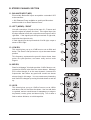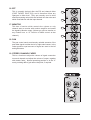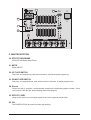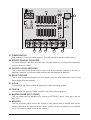
1
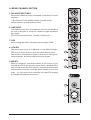
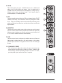
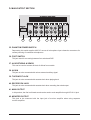
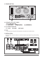
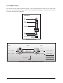
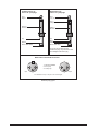
OWNERS MANUAL
A. IMONO CHANNEL SECTION
2~3
B. STEREO CHANNEL SECTION
4~5
C. MASTER SECTION
6~7
D. MAIN OUTPUT SECTION
8
E. POWER SECTION
9
F. INSTALLATION
9
G. CONNECTIONS
10~11
H. APPENDIX
12
Ultra low noise 10 Channel Mic / Line Mixer
6 Mono Input Channels with sliver plated XLRs and balanced Line Inputs
Ultra-low noise discrete Mic Preamps with +48 V Phantom Power
2 Stereo Input Channels with balanced XLRs and TRS Jacks
Extremely high headroom - offering more dynamic range
Balanced Inputs for highest signal integrity
Ultra-musical 3-band EQ on all channels
1 Aux Sends per channel for external effects and monitoring
256 DSP system inside
Highly accurate 6 segment Bargraph Meters
Separate master mix output
SAFETY INSTRUCTIONS
CAUTION:
To reduce the risk of electrical shock, do not remove
the cover (or back). No user serviceable parts inside;
refer servicing to qualified personnel.
CAUTION
RISK OF ELECTRIC SHOCK
DO NOT OPEN
WARNING: To reduce the risk of fire or electrical shock, do not
expose this appliance to rain or moisture.
This symbol, wherever it appears, alerts
you to the presence of uninsulated
dangerous voltage inside the enclosure
- voltage that may be sufficient to constitute a risk of shock.
This symbol, wherever it appears, alerts
you to important operating and maintenance instructions in the accompanying
literature. Read the manual.
1
A. MONO CHANNEL SECTION
1. BALANCE INPUT (MIC)
Electronially Balanced inputs acceptable a standard XLR male
connector.
+ 48V Phantom Power available on each input Mic socket.
and this switch is on Rear Phantom Power.
2. LINE INPUT
The unbalanced Mic input is provided for the use of an unbalance
mic and is designed to accept an unbalanced high impedance
input signal.
(This use for connection Deck, Turntable, Keyboard etc..)
3. PAD
When pushing this switch, attenuates the input signal -20dB.
4. LOW EQ
This control gives you up to 15 dB boost or cut at 80Hz and below.
This circuit is flat (no boost or cut) at the center detent position.
This frequency reptesents the punch in bass drums, bass guitar,
fat synth patches, and some really serious male singers.
5. MID EQ
Short for “midrange”, this knob provides 12 dB of boost or cut,
centered at 2.5KHz, also flat at the center detent. Midrange EQ is
often thought of as the most dynamic, because the frequencies
that define any particular sound are almost always found in this
range. You can create many interesting and useful EQ changes
by turning this knob down as well as up.
5
4
3
2
1
2
6. HI EQ
This control gives you up to 15 dB of boost or cut at 12KHz and
above, and it is also flat at the detent. Use it to add sizzle to
cymbals, and an overall sense of transparency or edge to keyboards, vocals, guitar, and bacon frying. Turn it down a little to
reduce sibilance, or to hide tape hiss.
10
9
7. EFF
This is normally derived after the EQ and channel fader (POST
FADER, POST EQ), and is therefore follow any changers in fader
level. They are normally used to drive effects processing units
which are fed back into the mixer and which must fade out with the
input channel.
8
7
8. MONITOR
This has a function which controls the volume on only channel
want to monitor with monitor amplifier and sends the signal by
Monitor output. (Unless you will use monitor on any channel turn
to “O” Position of MON control at that channel.)
6
9. PAN
The pan control sends continuously variable amounts of the post
fader signal to either the left or righ main busses. In the center
position equal amounts of signal are sent to the left and right
busses.
10. CHANNEL FADER
This is function to adjust the volume of signal connection into
each channel and adjust the volume of output, together with
master fader. Normal operating position is at the “O” mark,
providing 4dB of gain adove that point, if required.
3
B. STEREO CHANNEL SECTION
11. BALANCE INPUT (MIC)
Electronially Balanced inputs acceptable a standard XLR
male connector.
+ 48V Phantom Power available on each input Mic socket.
and this switch is on Rear Phantom Power.
12. LEFT (MONO) / RIGHT
Line with connection 1/4 jack as line input of L, R stereo and
input the signal of balance line level. If the signal input into
the input terminal of left side, output the mono output to left &
right side. If the signal input the input terminal of right side,
output into the right side only.
If each signal input the input terminal of left & right, output a
stereo of left & right.
15
13. LOW EQ
This control gives you up to 15 dB boost or cut at 80Hz and
below. This circuit is flat (no boost or cut) at the center detent
position.
This frequency reptesents the punch in bass drums, bass
guitar, fat synth patches, and some really serious male
singers.
14
13
14. MID EQ
Short for “midrange”, this knob provides 12 dB of boost or cut,
centered at 2.5KHz, also flat at the center detent. Midrange
EQ is often thought of as the most dynamic, because the
frequencies that define any particular sound are almost
always found in this range. You can create many interesting
and useful EQ changes by turning this knob down as well as
up.
15. HI EQ
This control gives you up to 15 dB of boost or cut at 12KHz
and above, and it is also flat at the detent. Use it to add sizzle
to cymbals, and an overall sense of transparency or edge to
key-boards, vocals, guitar, and bacon frying. Turn it down a
little to reduce sibilance, or to hide tape hiss.
4
12
11
16. EFF
This is normally derived after the EQ and channel fader
(POST FADER, POST EQ), and is therefore follow any
changers in fader level. They are normally used to drive
effects processing units which are fed back into the mixer and
which must fade out with the input channel.
19
18
17. MONITOR
This has a function which controls the volume on only
channel want to monitor with monitor amplifier and sends
the signal by Monitor output. (Unless you will use monitor on
any channel turn to “O” Position of MON control at that
channel.)
17
16
18. PAN
The pan control sends continuously variable amounts of the
post fader signal to either the left or right main busses. In the
center position equal amounts of signal are sent to the left
and right busses.
19. STEREO CHANNEL FADER
This is a function to adjust the volume of signal connection
into each channel and adjust the volume of output, together
with master fader. Normal operating position is at the “0”
mark, providing 4dB of gain adove that point, if required.
5
20
26
22
23
21
24
25
C. MASTER SECTION
20. EFFECT PROGRAMS
INDICATE 256 Digital Multi Effects.
21. MUTE
Effect ON/OFF.
22. UP TAPE SWITCH
One push, one program up push with more than 5 seconds hi-speed program up.
23. DOWN TAPE SWITCH
One push, one program down, push with more than 5 seconds, hi-speed program down.
24. Pre-set
Push more than 5 seconds, It automatacally memorize the displayed program number. Once
Just Push M1. M2. M3. M4, always display memorized program.
25. EFFECT LEVEL
Using by this control, you can adjust signal level of echo repeat & exteral effect.
26. ON
The POWER LED will be turned on when start working.
6
28
27
29
30
31
32
33
34
27. POWER SWITCH
Push marked (I), when you want to operate. The LED (26) will be turned on when working.
28. STEREO GRAPHIC EQUALIZER
2X7-band equalizer is provided for tone control over each frequency, and for precise high quality
sound by final tone control.
29. OUTPUTS LEVEL INDICATOR
This is level meter which shows output levels of left & right channel condition on the way of
operation, therefore, you can see output condition thru this master level indication.
30. EFFECT RETURN
This is used for adjusting frequency of echo repeat, since too echo repeat may cause a nowl,
please adjust frequency properly.
31. AUX IN
You can adjust the volume of AUX IN signal by this when connecting AUX IN.
32. TAPE IN
You can adjust the volume of TAPE in signal by this when connecting tape in.
33. MASTER FADER (LEFT / RIGHT)
This is a master fader for adjustment for volume of LEFT/RIGHT output. Unity gain is the top
their travel.
34. MONITOR
This has a function which controls the volume on only channel want to monitor with monitor
amplifier and sends the signal by Monitor output. (Unless you will use monitor on any channel
turn to “O” Position of MON control at that channel.)
7
D. MAIN OUTPUT SECTION
35
36
37
38
39
40
41
42
35. PHANTOM POWER SWITCH
Depressing this switch applies 48V DC across all microphone input channels connectors for
remote powering of condenser microphones.
36. FOOT SWITCH
This jack used for converting between foot switch and DSP.
37. AUX RETURNS & SENDS
This can be used to connect all kinds of effects from outside.
38. AUX IN
This jack is to be connected with various external auxiliary signal.
39. TAPE INPUT JACK
This jack is to be connected with cassette deck when playing back.
40. RECORD PIN JACK
This jack is to be connected with cassette deck when recording the mixed output.
41. MAIN OUTPUT
In this product, the final confirmed sound can be send to main amplifier through XLR & 1/4 jack.
42. MONITOR OUTPUT
This jack to be connected with the input jack of monitor amplifier when using separate
monitor amplifier.
8
E. POWER SECTION
45
44
43
43. SPEAKER JACK (LEFT / RIGHT)
44. AC POWER CORD/FUSE
45. FAN
In order top prevent rising the inside temperature, the inside heat is emitted outside.
F. INSTALLATION
Experience tells us that the cables in a studio environment get tangled very quickly (inviting
mistakes).
+6
SURROUND
+3
+1
MODEL-DVP-3000
AMPLIFIER
DIGITAL
0
-1
-3
L
-6
dB
R
01
09
17
25
02
10
18
26
03
11
19
27
04
12
20
28
05
13
21
29
06
14
22
30
07
15
23
31
08
16
24
32
POWER
TAPE
OUTPUT
L&R
INPUT
L&R
9
G. CONNECTIONS
You will need a lot of cables for different purposes - see the following figures to make sure you have got the
right ones. Unbalanced equipment may be connected to balanced inputs/outputs. Either use mono 1/4" jacks
or connect ring and sleeve of TRS jacks.
Headphones
Tip =
Left signal
Ring =
Right signal
Sleeve =
Ground / Shield
Tip
Ring
Sleeve
Strain relief clamp
Headphone connection
Output
Cable
Input
Ground
Pin 1
2
1
Pin 2 = (+) Signal
3
Shield
(+) Signal + Hum
(-) Signal + Hum
Pin 3 = (-) Signal
1
2
Positive
(+)Hum + Signal
Negative
(-)Hum + Signal
3
2 x Signal
RFI and Hum
Compensation of interference with balanced connections
10
= Signal + 6 dB
Unbalanced use of
mono 1/4" jack plugs
Balanced use of
stereo 1/4" jack plugs
Tip =
Signal
Tip =
hot (+ve)
Ring =
cold (-ve)
Sleeve =
Ground / Shield
Sleeve =
Ground / Shield
Tip
Tip
Sleeve
Ring
Sleeve
Strain relief clamp
Strain relief clamp
For connection of balanced and
unbalanced plugs, ring and sleeve have
to be bridged at the stereo plug.
Balanced use with XLR connectors
2
1
3
1 = Ground / Shield
2 = hot (+ve)
3 = cold (-ve)
1
Input
2
3
Output
For unbalanced use pin 1 and pin 3 have to be bridged
Different plug types
11
H. APPENDIX
Specifications
Mono Inputs
Mic Input
Bandwidth
Distortion (THD & N)
Mic E.I.N (22 Hz - 22 kHz)
TRIM range
electronically balanced, discrete input configuration
10 Hz to 60 kHz ± 3 dB
0.01% at +4 dBu, 1 kHz, Bandwidth 80 kHz
-129.5 dBu, 150 Ohm source
-117.3 dBqp, 150 Ohm source
-132.0 dBu, input shorted
-122.0 dBqp, input shorted
+10dB to +60dB
Line Input
Bandwidth
Distortion (THD&N)
Line level range
electronically balanced
10 Hz to 60 kHz ± 3 dB
0.01% at +4 dBu, 1 kHz, Bandwidth 80 kHz
+10 dBu to -40 dBu
Equalization
Hi Shelving
Mid Range
Lo Shelving
12 kHz +/-15 dB
2.5 kHz +/-15 dB
80 Hz +/-15 dB
Steroe inputs
Line Input
Bandwidth
Distortion (THD & N)
unbalanced
10 Hz to 55 kHz ±3 dB
0.01% at +4 dBu, 1 kHz, bandwidth 80 kHz
Equalization
Hi Shelving
Mid bell
Lo Shelving
Lo Cut (High Pass) filter
12 kHz +/-15 dB
100Hz -8KHz +/- 15dB, Q fixed at 1 oct
80 Hz +/-15 dB, Q fixed 2 oct
-3dB at 75Hz, 18dB / oct
Master Mix section
Max Output
Aux Send Max Out
Control Room Out
Signal-To-Noise Ratio
+22 dBu balanced
+22 dBu unbalanced
+22 dBu unbalanced
112 dB, all channels at Unity Gain
Power supply
Mains Voltages
12
USA/Canada
U.K./Australia
China
120V 60Hz
240V 50Hz
220V 50Hz