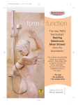
1
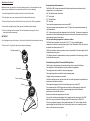
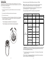
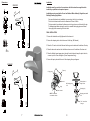
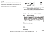
AFTER CARE
Your fitting has a high quality finish and should be treated with extra care to prevent the visible
surfaces.
All surfaces will wear if not cleaned correctly. Use a soft damp cloth with clean soapy water to
clean the surfaces. Stains can be removed with using washing up liquid. Do not use any other
cleaning solution or abrasive cloths or wire cleaners as this may damage the surface of the tap.
If the cloth used to clean the tap has previously been used with a cleaner that contains bleach
take special care to thoroughly rinse the cloth with clean water before use.
INSTALLATION AND OPERATING INSTRUCTIONS FOR
THERMOSTATIC BASIN MIXERS COMPLYING WITH N.H.S ESTATES
MODEL ENGINEERING SPECIFICATION D08
THE VALVE COVERED IN THIS BOOKLET HAS BEEN TESTED AND APPROVED TO N.H.S
ESTATES MODEL ENGINEERING SPECIFICATION D08
SF1053CP - Sola Thermostatic Mono Tap TMV3 with copper pipes
SF1054CP - Sola Thermostatic Mono Tap TMV3 with flexi hoses
LP - WE
HP - WE
LOW PRESSURE WASH BASIN
HIGH PRESSURE WASH BASIN
Note : These basin mixers are factory fitted with a lime green 2.75l
flow limiter (hot side) and grey 6l flow limiter (cold side) to comply
with BREEAM regulations (flow rates less than 6.0l/min at 3.0 bar).
Please refer to page 6 in these instructions prior to installation and
for the removal of flow limiters for use in Low Pressure installations
and changing the Hot side flow limiter used in High Pressure
installations when BREEAM flow rates are not required.
TMV3 approval information available on request
WRAS approval information available on request
Twyford Bathrooms
Lawton Road
Alsager
Stoke-on-Trent
ST7 2DF
UK
UK Technical Helpline
Telephone: 0844 412 5951
Fax: 0844 412 5922
Email: [email protected]
800442A
INTRODUCTION
NOTES:
It has been recognised that users of hot water in care establishments are at risk from
scalding. This risk has been reduced by the use of thermostatic mixing valves. In order to
assure the performance of thermostatic mixing valves N.H.S. Estates Model Engineering
Specification DO8 was written. The valves listed in the following pages have been tested and
approved to this standard by a third party as part of the BUILDCERT scheme for use within
their designated applications.
The following abbreviated designation codes are used throughout this booklet. Detailed
descriptions are given below:HP
LP
S
B
W
T44
T46
High pressure
Low pressure
Shower
Bidet
Washbasin
Bath with fill temperature of 44°C max
Bath with fill temperature of 46°C max
THE SF1053CP & SF1054CP BASIN MIXERS HAVE BEEN APPROVED FOR USE IN
THE FOLLOWING TMV3 DESIGNATIONS :-
CODE
LP-WE
HP-WE
OPERATING PRESSURE APPLICATION
LOW PRESSURE
BASIN MIXER
HIGH PRESSURE
BASIN MIXER
For full installation instructions and method of temperature adjustment see General
Assembly and Servicing Guide.
INSTALLATION RECOMMENDATIONS
The following general recommendations should be observed.
1) The thermostatic mixing valve should be installed in such a position that maintenance and
the commissioning and testing of the TMV can be undertaken.
2) Always flush both supply pipes fully before connecting mixing valve to ensure no pipe
debris enters the inlets. Always fit filters provided.
3) All installations must comply with current local Water Company Regulations.
CONDITIONS FOR NORMAL USE
In order to give compliance with N.H.S. specification DO8 scheme. The tables below list the
conditions for normal use, the valves may perform adequately outside these parameters but
the TMV3 scheme approval does not apply. If they are required to work with other supply
.conditions an engineer must carry out a risk assessment and satisfy themselves that the units
are still suitable for use.
1
14
Faultfinder
Table 1: Conditions for normal use
Fault
No or reduced flow and/or
fluctuating temperature
Maximum outlet temperature
too hot
Maximum outlet temperature
too cold or runs cold after a
short time
Cause
One or both isolating valves not
fully open
Open both valves fully
Flow limiters incorrectly fitted
Check information and refit
correctly
Tap will not shut off or dripping
Low Pressure
High Pressure
10
10
Flow Pressure, Hot & Cold (bar)
0.2 to 1
1.0 to 5.0
Hot Supply Temperature (°C)
52 to 65
52 to 65
Cold Supply Temperature (°C)
5 to 20
5 to 20
Minimum temperature differential between mixed
temperature and either supply
10°C
10°C
Maximim Static Pressure
Alter system to increase supply
pressures
Supply pipes blocked
Rectify system fault
COMMISSIONING
Waterways in tap blocked
Clear debris or call service
department
Since the installed supply conditions may differ from those used in testing and setting the
valves during final inspection and a valve may have several designations, it is necessary to
reset the mix temperature. The following procedure should be used after ensuring:-
Supply pressures unequal
Check maximum pressure
differential, and check if flow
limiters correctly fitted
Reset temperature see
calibration section
Reset temperature see
calibration section
Maximum mixed water
temperature incorrectly set
Maximum mixed water
temperature incorrectly set
Flow limiters incorrectly fitted
Maximum mixed water
temperature incorrectly set
Increase water temperature by
adjusting storage temperature or
power input to the system
See section on flow limiters
Reset temperature see
calibration section
Inlet supplies reversed
Seal damaged or worn
Re pipe supplies
Renew seals from spare parts kit
Service and descale fitting
Scale build up in body
No thermostatic fail safe
Operating Pressure Range
Inlet pressures below specified
values
Hot water temperature too low
Mixed water flow too high
Only hot or cold water at outlet
Repair
Inlet pressure above maximum
static pressure rating
Inlet temperatures outside
specification
Reduce pressure possibly by
fitting reducing valve
Reset boiler or recirculation
temperatures
Debris trapped in mechanism or
mechanism jammed
Strip and clean unit or call the
service dept
Inlet supplies reversed
. Re pipe supplies
13
a) The designation of the thermostatic mixing valve matches the intended application (i.e. if
a shower is to be supplied at 2 bar then the valve must have a HP-S designation).
b) The supply pressures match those for which the valve has been approved, see table1 and
valve details.
c) The supply temperatures are such that they are within the permitted range (see table1)
and comply with guidance information on the prevention of legionnella.
Note:- If the supply conditions are not within the parameters for normal use the valve may
still be suitable, but individual engineers must carry out their own risk assessment and satisfy
themselves that the units are still suitable for use. Adjust the mixed water temperature in
accordance with table 2, the method of adjustment is covered in the section Temperature
Setting.(See page 9)
Table 2: Mixed Water Temperature
Application
Bidet
Shower
Washbasin
Bath (44°C fill)
Bath (46°C fill)
Abbreviated Designation
-HP-B, BE,-LP-B, BE
-HP-S,SE;-LP-S, SE
-HP-W,WE: -LP-W, WE
-HP-T44; -LP-T44
-HP-T46; -LP-T46
Mixed water temperature °C
38 max
41 max
41 max
44 max
46 max
Note 1: For washbasins, washing under running water is assumed.
Note 2: Bath fill temperatures of more than 44°C should only be available when the bather is
always under the supervision of a competent person (e.g. nurse or care assistant)
Note 3: A thermostatic mixing valve having multiple designations (i.e. it is capable of
satisfying the requirements of this specification for more than one application) should
be re-set on site to suit the designation required.
2
The following set of tests should be carried out.
Maintenance
a) record the temperature of the hot and cold water supplies.
b) record the temperature of the mixed water at the largest draw-off flow rate
c) record the temperature of the mixed water at a smaller draw-off flow rate, which shall be
measured.
d) isolate the cold water supply to the mixing valve and monitor the mixed water temperature.
e) record the maximum temperature achieved as a result of (d) and the final temperature.
f) record the equipment, thermometer etc. used for the measurements.
If there is damage to the cartridge this will require dismantling and relevant
parts replacing [to dismantle follow these steps].
IN-SERVICE TESTING
The purpose of in-service testing is to regularly monitor the thermal performance of the
thermostatic mixing valve. Deterioration in performance can indicate the need for service
work to be carried out on the system.
Remove the cartridge as per previous stage.
1. Unscrew the half cartridge by
placing a thin blade through the
slots in the side, if possible hold
the head work assembly in a vice
or work mate.
[Standard right hand thread].
Circlip
Head
If the authority concerned does not have a planned test and maintenance schedule then the
suggestions below should form the basis of a new system.
PTFE Washer
At intervals of 6 - 8 weeks and 12 - 15 weeks after commissioning:1. Check supply parameters are still within the expected values if not check system for faults.
2. Carry out commissioning procedures a) to c) using the same test equipment, if the mixed
water temperature has changed a significant amount (by more than 1K) check to ensure
in-line filters are clean, that the check valves are working and all isolating valves are fully
open. If no fault can be found check and record the mixed water temperatures and re
-adjust mixed water temperature to the values in table 2.
Complete the commissioning procedure a) to f) if the mixed water temperature exceeds the
values of the maximum recorded temperature by more than 2K the need for service work is
indicated (see relevant instruction leaflet.)
Depending on the results of these two tests the following should be adopted
2. Remove the circlip
from the flow head,
and push the flow head
assembly through the head.
O’ring
3. Remove the PTFE washer from
the flow head. You are now able to
unscrew the flow head from the
shut off head [left hand thread].
Remove o’ring from shut off head.
Shut Off
Head
**O’ring
a) If a small change (e.g. 1K to 2K) occurs in one of these tests or there is no significant
change (e.g. 1K maximum) then the next in service test should be 24 to 28 weeks after
commissioning.
b) If small changes occur in both test or a larger change occurs in one test (exceeding 2K)
then the next in service test should be carried out 18 to 21 weeks after commissioning.
These results can then be used to set a service interval which tests have shown can be used
with no more than a small change in mixed water temperature. This method of determining
service intervals is used to take into account various in-service conditions (I.e. water
condition) that the valve may experience.
NOTE: Valves operating outside these conditions cannot be guaranteed by the Scheme to
operate as Type 3 valves.
O’ring
4. Unscrew the adjusting
screw from the shut off head
and remove o’ring.
**The o’ring located in the bottom
of the shut off head is peened
and can not be removed.
Adjusting
Screw
Half Cartridge
O’ring
5. Check all ‘O’ rings to ensure they are not damaged. Clean all brass parts in mild soap
solution such as washing-up liquid. Rinse with clean water.
6. Reassemble in reverse order.
3
Flow Head
12
Maintenance Continued
Maintenance may be required on the internal working parts of your thermostatic mixer tap.
Spare parts are available from the manufacturer [see front cover for address].
1. Isolate the supplies via the isolation valves on the end of the inlet tails.
2. Run the tap to remove any excess water from the thermostatic mixer tap.
3. Remove the grub screw from the back of the lever (use the 2mm Allen key provided).
4. Unscrew the cartridge using a 32mm spanner. [Standard right hand thread].
5. Once the cartridge has been remove from the thermostatic mixer tap pull out the
thermostat and piston assembly.
IMPORTANT
Do not damage any faces of the piston, this will result in failure of the thermostatic mixer tap
6. Remove all ‘O’ rings from the tap body and replace if damaged.
Recommended outlet temperatures
The BuildCert TMV scheme recommends the following set maximum mixed water outlet
temperatures for use in all premises:
44°C for bath fill but see notes below;
41°C for showers;
41°C for washbasins;
38°C for bidets.
The mixed water temperatures must never exceed 46°C.
The maximum mixed water temperature can be 2°C above the recommended maximum set
outlet temperatures.
46°C is the maximum mixed water temperature from the bath tap. The maximum temperature
takes account of the allowable temperature tolerances inherent in thermostatic mixing valves
and temperature losses in metal baths.
It is not a safe bathing temperature for adults or children.
The British Burns Association recommends 37 to 37.5°C as a comfortable bathing
temperature for children. In premises covered by the Care Standards Act 2000, the maximum
mixed water outlet temperature is 43°C.
The fitting of isolation valves is required as close as is practicable to the water supply inlets of
the thermostatic mixing valve.
Cartridge assembly
The fitting of strainers is recommended as close as is practicable to the water supply inlets of
the thermostatic mixing valve.
Commissioning notes for Thermostatic Mixing Valves.
The first step in commissioning a thermostatic mixing valve is to check the following:
The designation of the thermostatic mixing valve matches the application.
Thermostat
The supply pressures are within the valves operating range.
The supply temperatures are within the valves operating range.
Piston assembly
Spring
Isolating valves (and strainers) are provided.
If all these conditions are met, proceed to set the valve outlet temperature as stipulated in the
manufacturer installation instructions.
The mixed water temperature at the terminal fitting must never exceed 46oC.
It is a requirement that all TMV3 approved valves shall be verified against the original set
temperature results once a year. When commissioning/testing is due the following
performance checks shall be carried out.
Measure the mixed water temperature at the outlet.
Body
Carry out the cold water supply isolation test by isolating the cold water supply to the TMV,
o
wait for five seconds if water is still flowing check that the temperature is below 46 C.
If there is no significant change to the set outlet temperature (±2°C or less change from the
original settings) and the fail-safe shut off is functioning, then the valve is working correctly
and no further service work is required.
11
4
Maintenance & Removal of Flow Limiters
Notes
If there is a residual flow during the commissioning or the annual verification (cold water
supply isolation test), then this is acceptable providing the temperature of the water seeping
o
from the valve is no more than 2 C above the designated maximum mixed water outlet
temperature setting of the valve.
Temperature readings should be taken at the normal flow rate after allowing for the system to
stabilise.
If the mixer tap has operated correctly for a time, but no longer performs acceptably, it may
require servicing / cleaning.
The check valves, flow limiters, and filters are all located in the base unit of the tap.
[Removal as follows]
The sensing part of the thermometer probe must be fully submerged in the water that is to be
tested.
1. Isolated the hot & cold supply via the isolation units on the inlet tails. (Run the tap to
ensure no water is left in the supply pipes).
Any TMV that has been adjusted or serviced must be re-commissioned and re-tested in
accordance with the manufacturers' instructions.
2. Unscrew the grub screws located at the back of the tap near the base. (Use the 2.5mm
allen key provided).
The installation of thermostatic mixing valves must comply with the requirements of the Water
Supply (Water Fittings) Regulations 1999.
3. The tap can now be lifted off the base unit.
FLOW RATES
4. Pull out the brass containment units and push the check valves, flow limiters and filters out.
The flow rates (L/min) for the tap with and without flow limiters are quoted in the table below
5. Wash in clean running water and reassemble in reverse order.
Pressure Drop Bar
Low Pressure Flow Rate without Limiters
High Pressure Flow Rate with limiters
(Pink 4l Hot side &
Grey 6l cold Side)
High Pressure that conforms to
BREEAM flow rate for Basin
Mixers < 6.0l/min at 3.0 Bar
Flow Rate with limiters
(Lime Green 2.75l Hot side &
Grey 6l cold Side)
Supplied Factory Fitted
0.1
0.2
0.4
0.6
0.8
3.5
5.4
6.5
7.5
8.5
1.0
1.5
2.0 3.0 4.0
5.0
Not recommended, use flow
regulators as below.
Use Low Pressure
Setup
7.2
8.1
8.9
9.4
9.8
10.2
Use Low Pressure
Setup
4
4.5
5
5
5
5
Mesh filter
Use of flow limiters
Containment unit
This product will be factory fitted with a lime green 2.75 litre & grey 6 litre flow limiters and also
supplied with a standard Pink 4 litre flow limiter for low/high pressure installations. The 2.75l flow
limiter is fitted to comply with BREEAM flow rates for a basin mixer of no less than 6l/min at 3.0
bar.
Flow limiter
The lime green 2.75l flow limiter is positioned in the hot side and the Grey 6l flow limiter positioned
in the cold side, this is required when a high pressure system is used.
Check valve
Recommended:
Location of grubscrews
Recommended Minimum Dynamic Supply Pressure: 0.2 Bar
NOTE: For Dynamic supply pressures below 0.5 bar we recommend removal of the flow
regulators to allow increased flow.
Minimum cold water supply temperature: 5°C
Maximum cold water supply temperature: 20°C
Maximum hot water supply temperature: 80°C
5
10
Temperature Setting
Maximum dynamic pressure: 5.0 bar & Maximum static pressure: 10.0 bar
The tap will have been factory setup to deliver a maximum temperature of 41°C. The site
conditions and end users preferences will require the maximum temperature to be reset. This
can be achieved by the following steps;
1. Turn the tap to the full open position.
NOTE: A suitable hot water temperature control device should be installed to reduce
temperatures exceeding the above maximum hot water supply temperature.
Minimum temperature differential between hot supply and outlet temperature: 10°C
(eg. Outlet temperature 41°C - minimum hot supply 51°C)
2. Remove the targa button using a small flat bladed screw driver thus revealing the
grub screw.
Factory preset temperature: 41°C & Thermostatic control range: 38 - 45°C
3. Now using the 2mm Allen key provided unscrew the grubscrew.
Supply System
4. The lever can be removed.
5. When looking down onto the top of the cartridge you will be able to see the adjusting
screw with a hexagon centre. Turning this with the 2.5mm allen key (provided) will
increase or decrease the Temperature.
+
Turn the adjusting screw clockwise for cooler temperature.
+
Turn the adjusting screw anti-clockwise for warmer temperature.
Flow Limiter
Cold Supply
Hot Supply
0.1 to 5.0 bar
0.1 to 5.0 bar
(10 to 50 kPa)
(0 to 50 kPa)
0.5 to 5 bar
0.5 to 5.0 bar
(50 to 500 kPa)
(50 to 500 kPa)
or Pumped
or Pumped
Cold
Hot
No
No
Grey
(6 Litre)
Pink
(4 Litre)
Grey
(6 Litre)
No
Grey
(6 Litre)
Pink
(4 Litre)
Comments
Maxium Pressure
*** loss ratio 10:1
Gravity
0.2 to 5.0 bar
(20 to 50 kPa)
r
me
ar
W
Gravity above 0.5 bar
Coo
ler
(50 kPa)
Unvented Mains
Pressurised
Mains
1.5 to 10 bar
(150 to 1000kPa)
Instantaneous
Grey
Pink
Gas Water Heater
(6 Litre)
(4 Litre)
** Instantaneous
Grey
* Pink
Electric Water Heater
(6 Litre)
(4 Litre)
Grey
(6 Litre)
# Lime Green
(2.75 Litre)
Instantaneous
Grey
# Lime Green
Gas Water Heater
(6 Litre)
(2.75 Litre)
Gravity above 0.5 bar
(50 kPa)
Unvented Mains
Pressurised
* Pink (4 litre) limiter may not be necessary on some gas heaters.
** IMPORTANT It is a requirement of Instantaneous Electric Water Heaters that a stable flow
of water passes through a heater. Failure to regulate outgoing water from the heater may
result in fluctuating temperature at the tap.
*** For example a pressures of incoming supplier i.e. 0.1 (hot side) and 1.0bar (cold side)
would give a 10:1 ratio.
# This flow limiter is for High pressure installations when reduced flow economy rates are
needed in compliance with BREEAM Regulations.
9
6
Dimensions:
Installation
SF1053CP
Installation must be carried out in accordance with the instructions supplied and be
installed by a qualified and competent person
57
115
45
130
Installations must comply with all Local and National Water Authority Regulations, and
Building/Plumbing Regulations.
- Care must be taken during installation to prevent any risk of injury or damage.
- The hole in the basin must consist of a diameter of 30mm to 36mm.
- The tap needs to be positioned to allow access to the grub screw on the back of the tap.
- To eliminate pipe debris entering the valve it is essential that supply pipes are flushed
thoroughly before connecting to the inlet tails.
FINAL INSTALLATION
1. Ensure the inlets tails are fully tightened into the base unit.
60
155
2. Secure the clamping studs into the base unit of the tap. (M6 threads).
3. Place the ‘O’ seal over the inlet tails and into the groove located onto the bottom of the tap.
4. Place the base unit seal over the inlet tails and secure on to the bottom of the base unit.
15
5. Place the flexible hoses/copper pipes through the sink hole and clamp the tap to the sink,
connect up to the 15mm inlet pipes. (15mm compression fixing).
6. Secure the tap in place with the rest of the clamping kit as per diagram.
SF1054CP
57
115
Tap body
O’ring groove
45
130
Base unit
O’ring
M6 Clamping stud
2 off
Flexible Hoses or
Copper Tubes
Clamping ring
Base unit seal
Clamping stud nut M6
2 off
NOTE: This seal sits
on underside of basin.
155
7/16” across flats
hexagon
15
7
8