1
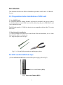
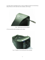
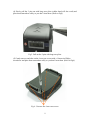
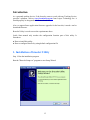
User’s Manual
Revision 1.21
Copyright 2009 by Laipac Technology Inc.
CONTENTS
4
4
4
For your safety
About your device
Network Services
8
Chapter 1: SIM card Installation Instruction
9 Preparation before installation of SIM card
9
A valid SIM card
9
Special tools for installation
9 SIM card Installation Steps
13 Care and Maintenance
14
15
15
19
21
21
22
23
24
25
29
29
30
31
31
32
32
32
32
32
33
33
33
34
34
34
35
35
36
36
37
37
Chapter 2: Utility Configuration
Introduction
Installation of Bracelet Utility
Installation of USB Driver
Configuring Bracelet
Start bracelet Utility
Enter into Configuration Mode
Configuring Bracelet by using default configuration file
Acquiring parameters of configuration from Bracelet
Bracelet configuration example
Saving Parameters
Exit Configuration Mode
Chapter 3: Operation Instructions
Scope
Features
Keys
Operation Instruction
Charging
Power On Unit
Initialization
Main menu
Operation
Emergency Call
Emergency Call Phone Book
Calling
Talking
Phone Book
Phone Book Selection
Short Message
Short Message Selection
Instant Geo Fence
Geo Fence setting
2
37
38
38
38
38
39
40
My Position
Show Current Position
Speed & Heading
Configuration
Configuration Selection Submenu
Other Operations
Remote Setting
3
For Your Safety
Read these simple guidelines. Not following them may be dangerous or illegal. Read the
complete user guide for further information.
Road Safety Comes First
Do not use the device for talk and text when wireless phone use is prohibited or
when it may cause danger.
Interference
All wireless devices may be susceptible to interference, which could affect
performance.
Switch Off In Hospitals
Switch the device off near medical equipment.
Switch Off In Aircraft
Follow any restrictions. Wireless devices can cause interference in aircraft.
Switch Off When Refuelling
Do not use the device at a refueling point. Do not use near fuel or chemicals.
Switch Off Near Blasting
Follow any restrictions. Do not use the device where blasting is in progress.
Qualified Service
Only qualified personnel may install or repair this product.
Batteries
Use only approved batteries. Do not connect to incompatible products.
Back Up Copies
It is recommended to save the phone book record and important settings.
Connecting To Other Devices
When connecting to any other device, read its user guide for detailed safety
instructions. Do not connect with incompatible products.
Emergency Calls
Ensure the phone function of the device is switched on and in service.
4
About Your Device
The wireless device described in this guide is approved for using GSM
850/900/1800/1900 networks. Contact your service provider for more information about
which GSM frequency your service provider is using. When using the features in this
device, obey all laws, respect privacy, and the legitimate rights of others.
Network Services
In order to use the S-911 Bracelet Locator, you must have GSM service from a wireless
service provider and subscribe with LocationNow. Many of the features in this device
depend on the features of the GSM provider to function. These network services may not
be available with all providers meaning you may have to make specific arrangements
with your service provider before you can utilize the network services. Your service
provider may need to give you additional instructions for their use and explain what
charges will apply. Some networks may have limitations that affect how you can use
network services in your area.
5
- Chapter 1 SIM card
Installation Instruction
6
Introduction
This document describes the SIM card installation procedure used for the S-911 Bracelet
Locator.
1.0 Preparation before installation of SIM card
1.1 A valid SIM card
A valid SIM (Subscribe Identity Module) card must be provided by the user in order to
use the Bracelet. Your local GSM Carrier will be able to provide you a GPRS DATA and
voice enabled SIM card.
The SIM card must be a 3V SIM, the bracelet is not compatible with the older 5V version
SIM cards.
1.2 Special tools for installation
(1) 2 special Phillips screwdrivers are needed for the SIM card installation, one is 1.4mm
in size and the other is 1.6mm in size.
(2) 1 long nose pliers (refer to Fig1).
Fig1. 1.6/1.4 mm Philips screwdrivers and long nose pliers
2.0 SIM card installation steps
(1) Push the Power on/off button to turn off the power supply (refer to Fig2).
Power on/off button (RED)
Fig2. Power on/off button (RED)
7
(2) Gently push the wristband pin with a 1.6mm size Philips screwdriver about 4mm deep
until pin comes out of the other end of the wristband. (refer to Fig3).
Fig 3. Push the pin out of the wristband
(3) Same operation on the second pin (refer to Fig4).
Fig 4. Example of 2 pins sticking out of the wristband
8
(4) Slowly pull the 2 pins out with long nose pliers (rubber band will also work) and
place them somewhere safely so you don’t loose them. (Refer to Fig5).
Fig 5. Pull out the 2 pins with long nose pliers
(5) Gently unscrew and take out the 4 rear case screws with a 1.4mm size Philips
screwdriver and place them somewhere safely so you don’t loose them. (Refer to Fig6).
Fig 6. Unscrew the 4 rear case screws
9
(6) Gently open the Bracelet main case (refer to Fig7).
Do not touch the PCB or any component inside. The ESD
(electrostatic discharge) can damage the unit permanently.
Fig 7. Please don’t touch the PCB or any components inside.
(7) Fully insert a valid SIM card into the SIM card holder, label-up. You will see that the
bottom edge of the SIM card firmly contacts the bottom line of the card holder. (Refer to
Fig 8).
Fig 8. Fully insert SIM card into the card holder
(8) Close the main case carefully, and gently fix the 4 screws, refer to Fig 5 and Fig 6.
(9) Reinstall and secure the wristbands carefully by gently pushing the 2 pins into
wristbands, refer to Fig 4.
10
CARE AND MAINTENANCE
Your device is a product of superior design and craftsmanship. The suggestions below
will help you protect your warranty coverage.
•
Keep the device dry. Precipitation, humidity, and all types of liquids or moisture
can contain minerals that will corrode the electronic circuits.
•
Do not store the device in hot areas. High temperatures can shorten the life of
electronic devices, damage batteries, and warp or melt certain plastics.
•
Do not attempt to open the device other than as instructed in this guide.
•
Do not drop, knock, or shake the device on purpose. It will trigger the tamper alert
to the monitoring centre.
•
Do not use harsh chemicals, cleaning solvents, or strong detergents to clean the
device.
11
- Chapter 2 Utility Configuration
12
Introduction
As a personal tracking device, if the bracelet wants to work with any Tracking Service
provider’s platform, such as www.LocationNow.com from Laipac Technology Inc. it
should properly be integrated with Protocol and API.
Also, to support future application firmware upgrades for the bracelet, it needs a tool to
download firmware.
Bracelet Utility is a tool to meet the requirements above.
Quick Start manual only touches the configuration function part of this utility. It
introduces:
● How to install this utility
● How to configure Bracelet by using default configuration file
1. Installation of bracelet Utility
Step 1: Run the installation program.
Run the "Bracelet Setup.exe" program to start Setup Wizard.
13
Step 2: Press the "Next" button to enter the page to Select Destination Location.
Step 3: If you don’t want use the default folder, please type the name of the new folder
and in box or press "Browse" open dialog to select another desired folder, then press the
"Next" button to enter the next page.
14
Step 4: Select the Start Menu Folder, and then press the "Next" button to go to the next
page.
Step 5: If you want to create a shortcut icon on your desktop, please check the "Create a
desktop icon" item. Then press the "Next" button to go to the next page.
15
Step 6: If nothing needs be changed, press the "Install" button. Otherwise, you can press
the "Back" button to go back to the previous page.
Step 7: After extracting the files to destination directory, the installation is finished. The
last step is optional which will ask if you want launch the Utility immediately. If you do
not want to run the utility, uncheck the "Launch Bracelet Utility" item and press "Finish"
to complete the installation. If the item is checked, the Utility will run after the
installation dialog is closed.
16
The next step is to install USB driver required by Bracelet Utility
2. Installation of USB Driver
The following steps are only required when Bracelet, at first time, connects to PC through
certain USB port, which has never gone through the installation procedure.
Step1 - Open the utility and select configuration
Step2 - Connect Bracelet and PC with USB cable
Step3 - Turn on Bracelet and ignore the display shown on Bracelet LCD screen
Step4 - Select proper Hardware Wizard and start USB Driver Installation
After several seconds the PC screen will show like above, then, check “Yes, this time
only” and click “Next” button
17
Select “Install the software automatically (Recommend)” and click “Next”
Remark
If the following message pops up, click “Continue Anyway”.
18
Once the automatic USB driver installation has completed, please click “Finish” to exit
3 Configuring Bracelet
3.1 Start Bracelet Utility
There are 2 ways to start this utility
Method 1 – Start from “Start Menu”
Run utility from Start Menu. Select Start MenuÆ All ProgramsÆ Bracelet UtilityÆ
Bracelet Utility.
Method 2 -- Start by using Desktop Shortcut
Run utility from Desktop. If you check "Create a desktop icon" during installation, you
can double-click the icon on desktop to launch it.
19
Click the “Configuration” button. By clicking this, you will select utility’s configuration
function
3.2 Enter into Configuration Mode
Step1 - Power on Bracelet unit and connect it to PC through provided Micro USB cable.
Step2 - Press “menu” key to enter into main menu.
Step3 - Select “Configuration” sub menu by pressing “Up” or “Down” key then press
“OK”.
Step4 - Select the 4th sub menu “PGM. Download” by pressing “Right” key and press
“OK”.
The “Resetting…” will be shown on Bracelet LCD Screen.
On the PC side, an information window will pop up at the corner of your screen, which
will say “Found a new device” followed by “Open COM#”
20
3.3 Configuring Bracelet by using default configuration file
If this is your first time configuring the Bracelet, to speed up the configuration process,
it’s suggested that you configure Bracelet by using default configuration file that comes
with Bracelet Utility. The file name is “Bracelet_configuration.cfg”. Otherwise, you can
go to section 3.4 directly.
Click “FILE” button on Top-left corner and select “open”. Then select your configuration
file from the directory which includes suggested configuration file and open it.
Turn to 3.5
21
3.4 Acquiring parameters of configuration from Bracelet
You can also acquire those parameters used for configuration by reading them from
Bracelet unit, which has been configured before.
Click the “Read setting from device” button as show bottom right corner of pic. A
window will pop up at the corner of your screen saying “Loading…” followed by
“Finished.”
22
3.5 Bracelet configuration example
Here is an example that shows you how to configure a Bracelet unit, which will be
registered on www.LocationNow.com
Step 1 Go through the procedure suggested by section 3.3
Step 2 Click GSM Band selection box and set correct band parameter from its drop-down
menu.
Click “Network” on the top.
23
GPRS APN: Provided by your SIM card provider, it is the carrier’s APN (access point
name) through which the device will transmit data to the Internet.
GPRS APN User Name: Provided by your SIM card provider, this is the username for
your device to access the carrier’s data network. If it doesn’t exist, leave blank.
GPRS APN Password: Provided by your SIM card provider, this is the username for
your device to access the carrier’s data network. If it doesn’t exist, leave blank.
Domain Name 1a: server gateway domain name.
Port 1a:
server gateway port.
Static IP 1:
server gateway static IP (for back up).
Port1:
server gateway port (for back up).
Note: the server setting parameters shown above is for our
LocationNow.com Server.
Click “SYSTEM” then click Phone book
24
Assistance number: When SOS event is generated, this number will be called.
Emergency Number 1-3: emergency phone book numbers.
SMS Base Station Number: When SOS event is generated this number will be sent an
SMS.
Phone Book: 10 phone book items.
25
Click “Messages” for 10 SMS setting
26
3.6 Saving parameters
Click “Save All Settings to Device” button. A window will pop up at the corner of your
screen saying “Saving…” followed by “Finished.”
So far you have completed all necessary setting for this unit. If you don’t need to
change any other parameters, you can press “Run Application” to run the
application on unit. If you need modify other parameters, please press
“Configuration again” back to setting window.
We suggest backing up of the unit parameters to a file. Next time just reload parameters
from this file and do the necessary modification.
4 Exit Configuration Mode
Step1 - Disconnect USB cable from Bracelet USB port
Step2 - Press “OK” and “Send” buttons at same time
Step3 - Release “OK” and “Send” buttons, Bracelet will enter into normal working mode
to run demo application.
27
- Chapter 3 Operation Instruction
28
Scopes
This document describes the S-911 Bracelet demo (V1.21) operation procedures. The
corresponding hardware version is V3.0.
Features
The main features include SOS and Emergency call, phone book, SMS, instant Geofence, real time position reporting, and setting parameters remotely.
Microphone
Menu
SOS / Assist
Menu Up
Menu Left
Menu Down
Speaker
Menu Right
Fig 1
Enter (OK)
Call /Send
USB
Power On / Off (Hang up call)
Fig 1
29
Key Layout
There are 7 keys on front and 2 keys on right side. See Fig 1 and Fig 2. Power on/off key
is also used to hang up a phone call.
Pre-Operation Instruction
Before operating the unit verify that the below three steps have been completed.
1. A valid SIM card has been installed. Refer to Chapter 1.
2. The configuration parameters have been set properly. Refer to Chapter 2.
3. The unit has been charged with enough power.
Charging
There are three main conditions for charging the unit listed below.
1. When the unit is off
¾ Connect the USB cable to the charger. The LCD shows Fig 3. The
flashing battery ICON means charging. Stable with full battery bar ICON
means that the unit has finished charging. If you unplug the USB cable,
the unit will shut down by itself.
2. When the unit is on.
¾ Connect the USB cable to charger. The battery ICON on main menu will
flash.
3. Unit is on and is at full charging status
¾ Connect the USB cable to charger. Press power on/off key and hold for 4
seconds. The Unit will change to full charging status like 1.
For conditions 1 & 3, the display shows “charging” and will switch to “Complete”
with a full battery bar ICON, when the unit is fully charged.
For condition 2, when the battery finishes charging, the battery ICON will stop
flashing.
Fig 2
Powering the Bracelet
To power the bracelet, press the power on/off key for 3 seconds. The LCD backlight will
flash 3 times and initializing information will be shown on the display. See Fig 5. The
initializing procedure will take approximately 3 seconds.
Fig 3
30
Main Menu
After initializing, “Main Menu” is shown on LCD display, see Fig 6. The ICON to the
left outlines the status of GSM. The time is shown in the middle. The ICON on the far
right is for battery status and the one next to battery icon is used to indicate the status of
GPS.
GSM ICON: The ICON on Fig6 means GSM is fixed and provides how many bars it is
connected with or otherwise shows it is trying to connect to GSM.
GPS ICON: Flashing “G” means GPS is trying to connect and a stable “G” means GPS
has connected.
Fig 4
Menu Operation
The menu key is the main button that allows the bracelet operator to access the available
menu structure. The main menus that will be covered in this section are: Emergency
Call, Phone Book, Short Message, Instant Geo-fence, Current Position, Speed and
Heading, and Configuration.
The instructions to navigate through these menus are listed below.
Left key: the menu title will scroll from the left side.
Right key: a part of the menu title will be shown and then scrolls across the display.
Up/Down: Navigates through menu or sub menu options.
Menu key: Returns to the Main Menu.
OK: Confirms the current selection.
1. Emergency call (see Fig s1)
Fig s1
The first sub menu “Emergency Call” will be shown on the LCD after pressing the menu
key (see Fig s1). Only a part of menu title is on the screen at first. After 2 seconds, the
menu title will start to scroll until any function key is pressed and stop after 45 seconds of
inactivity.
31
1.1 Emergency call phone book
Press Left key: displays the name (see Fig s1.1.1).
Press Right key: displays the phone number (see Fig s1.1.2).
Press Up/Down: selects another phone book item.
Press Menu key: will return to the Main Menu.
Press OK: confirms the selection and calls the number.
Fig s1.1.1
Fig s1.1.2
1.2 Calling
Fig s1.2
Press the Menu key or the Hang up key to cancel current call and return to the Main
Menu. If call is successful, the display in figure 1.3 will appear.
1.3 Talking
Fig s1.3
This display indicates that a 2-way voice session is open and counts the duration of the
call.
By pressing the hang up key will hang up the current call and return to the Main Menu.
By pressing the Menu key will return to the Main Menu screen while keeping the voice
session open.
32
2. Phone Book (see Fig s2)
Fig s2
2.1 Phone Book Selection
Press Left key: displays the name (see Fig s2.1.1).
Press Right key: displays the phone number (see Fig s2.1.2).
Press Up/Down: selects another phone book item.
Press Menu key: will return to the Main Menu.
Press OK: confirms the selection and calls the current number.
Fig s2.1.1
Fig s2.1.2
33
3. Short Message (see Fig s3)
Fig s3
3.1 Short Message Selection
Press Left key: displays the name (see Fig s3.1.1).
Press Right key: displays the short message (see Fig s3.1.2).
Press Up/Down: selects another name or SMS item.
Press Menu key: returns to the Main Menu.
Press OK: confirms the selection and sends an SMS to the phone number belonging to
this name.
Fig s3.1.1
Fig s3.1.2
34
4. Instant Geo-fence (see Fig s4)
Fig s4
4.1 Geo Fence setting
Press Left/Right: selects different instant geo fence range.
Press Up/Down: sets the current geo fence to available or unavailable.
Press Menu key: returns to the Main Menu
Press OK: confirms the current selection and setting and then returns to the Main Menu.
Fig s4.1
5. My Position (see Fig s5)
Fig s5
5.1 Shows the current position (Latitude/Longitude)
Press the Menu key to return to the Main Menu.
Fig s5.1
35
6. Speed & Heading (see Fig s6)
Fig s6
6.1 Shows the current heading and speed (km/hr)
Press the Menu key to return to the Main Menu.
Fig s6.1
7. Configuration (see Fig s7)
Fig s7
7.1 Configuration selection sub menu (see Fig s7.1)
Press Left/Right: sub menu or functions selection
Press OK: confirms and goes to the selected submenu.
Press Menu: returns to Main Menu
Fig s7.1
7.1.1: Set date and time
36
7.1.2: Set time zone.
Fig s7.1.2
Press Up/Down: changes the current value
Press OK: confirms the current menu operation setting and returns to the Main Menu
Press Menu: cancels the current menu operation setting and returns to the Main Menu
7.1.3: Set alarm.
Fig s7.1.3
Press Up/Down: changes the current value
Press Left/Right: selects the next operation item
Press OK: confirms the current menu operation setting and go back to the Main Menu
Press Menu: cancels the current menu operation setting and returns to the Main Menu
7.1.4: PGM. Download.
Press OK, and the Unit will reboot with the LCD screen showing “Resetting……”
Call/Send Key Operations
If GSM is not fixed, press the call/send key and the unit will start to connect with GSM.
To go to the phone book menu directly, press the call/send key. This can only be
accomplished when the bracelet is connected to GSM.
SOS Key Operations
Press and hold the SOS key for 5 seconds, see Fig 5
1) Sends the SOS information to central server by GPRS.
2) Sends the SOS SMS to emergency phone1.
3) Calls the SOS phone number.
37
Fig 5
Press and hold the Power on/off key for 3-5 seconds and the unit will be shut down.
Remote Inquiring and Setting
Emergency phone numbers setting can be accomplished by remote configuration. See
Fig 6.
Fig 6
SOS phone number
Emergency phone number 1
Emergency phone number 2
38