1
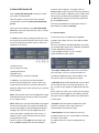
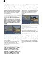
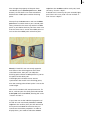
User manual
PiP-Studio 3D
for SMART EDIT
Contents
Page
1. General information.......................................................................................... 3
2. The PiP-Studio 3D program............................................................................. 3
3. Installation / Starting the program................................................................... 4
4. Operation ........................................................................................................... 4
4.1 Select PIP-Studio 3D preset ................................................................. 5
4.2 Start PIP-Studio 3D ............................................................................... 7
4.2.1 Scene menu ....................................................................... 7
4.2.2 Current path menu ............................................................ 8
4.2.3 Waypoint menu ................................................................. 9
4.2.4 Style menu ......................................................................... 10
5. Tutorials ............................................................................................................. 12
5.1 Creating a 3D transition ....................................................................... 12
5.2 Zooming in and out of a scene............................................................ 13
5.3 Placing two scenes opposite each other on one background .......... 16
Since it is possible that changes have been made to the software after the manual was printed, the functions
shown and described in this manual might differ from the software.
1. General information
Congratulations on purchasing the PIP-Studio
3D software product.
We would like to express our gratitude and hope
that the software meets your expectations.
This manual explains how to operate the PIPStudio 3D program.
For further going questions and suggestions,
don‘t hesitate to contact us.
Please use the following address. Makes sure to
have your unit‘s serial number or your customer
number at hand whenever you contact us.
If you have technical queries, you can reach us
using the following Technical Hotline telephone
number:
(North America)
Monday - Friday 9a.m. - 5p.m. (Mountain Standard Time)
303-801-1010
Outside of these times you can email or fax us.
Messages received in this way are handled
during business hours.
address
E-Mail Support
[email protected] (Germany)
[email protected] (North America)
[email protected] (N.A.)
[email protected] (N .A.)
MacroSystem Digital Video AG
Postbox 020240
58290 Wetter
Germany
Fax Support
+49 (0)2335/960-110 (Germany)
303-801-1058 (North America)
Users from the United States please contact
MacroSystem US
5485 Conestoga Court
Boulder, Colorado 80301
Phone
0 +49 (0)2335/960-0 (Germany)
303-440-5311 (North America)
eMail
[email protected] (Germany)
[email protected] (North America)
fax
0 +49 (0)2335/960-100 (Germany)
303-440-5322 (North America)
Current product information and sales related
details can be found on our web site:
http://www.macrosystem.com
2. The PIP-Studio 3D program
The PIP-Studio 3D program is based on the
popular Picture-in-Picture (PIP) function of the
Smart Edit software.
It is the consequent 3D Effect addition to the PIPStudio program.
With the predecessor, you could place a moving
scene onto any other one - in different forms
and with freely defined outlines. Many other
creative options such as the outline colour,
transparency and shadow cast have produced
appealing and professional results.
This concept has also been retained with
the PiP-Studio 3D, although the scenes and
outlines are displayed and animated in a three
dimensional form in space, which provides a lot
of scope for creativity.
This means that many objects/scenes can be
animated in different designs on their own
motion paths. You can use the Image Pool to
create outlines and of course 2D and 3D PIPs can
be combined together.
4
Other functions:
• Gradual acceleration and slowing down of the
PIPs on a motion path.
• Extensive library containing new forms.
• Free determination of the image extract for a
PIP.
• For an even more realistic display, you can
define up to three light sources to light up a PIP.
• The supplied default settings enable you to run
the program immediately.
General instructions:
Throughout this manual, you will often see the
word “PIP”. We use this term (ie. “Picture in
Picture”) for the video scene or video image,
which overlaps your background video.
3. Installation / Starting the
program
To install the PIP-Studio 3D software, you must
have system software Smart Edit 4.0 or later
(HDV is only possible with Smart Edit 5.2, or
version 6.1 or higher).
Leave your device switched on and, in the
System Settings screen, select the Install
product button to open the corresponding
window.
Take the SmartMedia installation card and insert
it into the drive, whilst making sure that the
gold-coloured contacts are facing downwards
and the bevelled corner is on the left (pointing
towards the device).
If the PIP-Studio 3D software is on a CD/DVD
and if your system has a DVD drive and DVDArabesk software, insert the CD/DVD into the
DVD drive.
After a few seconds (if you are using a CD/DVD,
the drive may make a noise which indicates that
the CD/DVD is being read by the system.), you
will see that the PIP-Studio 3D software is listed
in the Install product window. Select it from the
list and click on Activate.
After a while a numerical keypad appears. Use
it to enter the license code that you purchased
from your dealer. A message will then inform
you that the installation process has completed.
You can now remove the SmartMedia card or
CD/DVD.
If you want to install PIP-Studio 3D as a demo
version, first select it from the list and click on
Activate.
Afterwards, click on the Demo button in the
numerical keypad window.
You will now see the word Demo after the
program name. Confirm by pressing Ok and
then remove the SmartMedia card or CD/DVD.
PIP-Studio 3D has now been installed as a demo
version.
You can use all functions with this demo version,
but a “Demo” stroke is displayed on the effect
list after the calculation.
After you have installed the software, you will
see the PIP-Studio 3D program in the Image
processing effects menu in the list of effects
and listed alphabetically in the Edit menu under
Special.
4. Operation
The operation of the PIP-Studio 3D program is
explained in the sections that follow, using the
individual buttons.
This part of the user manual is for reference
purposes only for the individual program points.
If certain functions or menu items are unclear,
please refer to the relevant section for a more
detailed explanation.
Preparation
Select a scene for your background and insert it
into the storyboard.
Pull up the Image processing effects menu,
select the alphabetically sorted PIP-Studio 3D
operator from the list and add it to the scene.
5
Please make sure that the effect length is set
for the whole time of the scene which has been
added.
Then look at the options shown on the right next
to the effects list (see below).
4.1 Select PIP-Studio 3D preset
Use the Select PIP-Studio 3D preset function
to quickly create animations with a PIP (small
image on the scene) via a simple manager.
The settings which are defined here are
transferred to the PIP Studio 3D menu (see
Chapter 4.2 Starting PIP-Studio 3D), when you
then start the program.
We would recommend that you first try this way
of PIP creation to gradually familiarise yourself
with the program.
After you have clicked on the Select PIP-Studio
3D preset button, this takes you to a new menu,
which you can use to produce the first PIP effect
in two steps.
Note: If you want to use several PIPs in the
scene, you first have to create one PIP and then
create another PIP with the newly created scene.
In the first menu you have the option to create
the PIP sequence.
A preview of your scene is shown on the right
hand side of the menu. On top of that is a
moving red outline which displays the current
setting of the PIP paths.
The following settings options are displayed on
the left hand side of the menu:
• IN length: Use this slider control to set the time
at which the PIP should fade in. The maximum
length is the length of the scene.
• IN select: Here you select the fade-in path.
You’re taken to a menu where you can set the
behaviour of the path. Select Preset Type to set
a more accurate definition of the path property.
You can either select Simple, Zoom or Rotation.
Once you have selected your option, this
changes the settings in the list above.
Select Mirror to mirror the selected path and to
change it as such. The red box in the preview
always shows you the path which has been set.
Once you have set the behaviour of the path,
click on Ok.
• MID select: Click on this function and a menu
appears which you can use to set the behaviour
of the PIP during the middle phase. Select
Type to set a more accurate definition of the
path property. You can either select Simple,
Bouncing, Rotation or Pulsation. Selecting one
of these options changes the settings in the list
above.
Select Mirror to mirror the selected path and to
change it as such. The red box in the preview
always shows you the path which has been set.
Once you have set the behaviour of the path,
click on Ok.
6
• MID position: Use this function to determine
the central point of the path. The red preview
box changes to blue and you can move it by
moving the trackball pointer. Once you have
found the desired position for the central point,
click on the left trackball key to confirm.
• OUT length: Use the slider control to select
the time at which the PIP should fade out. Make
sure that the length set here, along with the IN
length, is actually the same as the overall length
of the scene. The maximum length which is
possible in this case therefore depends on the IN
length which has already been entered.
• OUT select: Use this function to select the fadeout path. This takes you to a menu where you
can set the behaviour of the path. Select Preset
Type to set a more accurate definition of the
path property. You can either select Simple or
Zoom. Once you have selected your option, this
changes the settings in the list above it which
can be selected.
Select Mirror to mirror the selected path and
change it as such. The red box in the preview
always shows you the path which has been set.
Once you have set the behaviour of the path,
click on Ok.
Once you have created the progress of the PIP,
click on Next in this menu which takes you
to a new menu where you can determine the
appearance of the PIP.
as an outline but it shows a scene – it is the
scene currently selected in the scene bin.
The following settings options are displayed on
the left hand side of the window:
• Select scene: Click on this button once to
display the scene bin from which you can now
select the desired scene for the PIP. Then click on
Ok.
• Extrusion: Click on this button to open the
image pool, and use the Product and Type
buttons to select a suitable image for the colour
of the outline, which surrounds the scene.
Then confirm your selection by pressing Ok.
• Size: Use this selection button to set the PIP
size. You can choose from eight settings.
• Bevel: Use this selection button to define the
bevelling of the outline edge.
• Shape: Use this selection button to define the
PIP format. A list appears with small preview
images of the possible formats.
Once you have created the appearance of the
PIP, click on Ok to exit the menu and accept the
settings.
(Press the Prev button to go back to the previous
menu, in order to make any corrections if
necessary. Press the Cancel button to reject the
settings which have been determined and to
return to the Image processing effects menu.)
In the Image processing effects menu, you can
now click on the Create button and then view
the result.
A preview is shown again in the right hand
side of the window, which displays your scene.
Furthermore, the PIP is now no longer displayed
7
4.2 Start PIP-Studio 3D
Use the Start PIP-Studio 3D function to create
your own customised PIP.
Use this option only once you have already
created a PIP scene from Select PIP-Studio 3D
preset.
Once you have clicked on the Start PIP-Studio
3D button, you will reach the first menu, namely
the scene menu.
In addition to the basic settings of the paths on
the scene which you will find in this menu, there
are also jump keys for other menus, which are
identical in all menus.
Another menu appears, and again click on
Select scene. From the scene bin which appears,
you can now select a different scene. Then close
the scene bin and the next window by clicking
on Ok and then click on the relevant symbol to
go to the Scene menu.
The exact procedure for creating the menu is
described in Chapter 4.2.4 Style.
4.2.1 Scene menu
In this menu you can determine the global
settings of the path. You can also add or delete
other paths.
You can also define the lighting effect, for which
up to three light sources are available and which
can be individually adjusted.
In the background you can see a large
representation of your scene.
(1) Scene menu
(2) Current path menu
(3) Waypoint menu
(4) Style menu
(5) End program, accept all settings
In addition, you will also see three buttons
on the left hand side of the screen, which are
used to minimize the bar, move the bar to the
opposite side of the screen and call up a preview
(Play symbol).
Note: The preview shows the background image
and displays the PIP scene(s) which are placed
on it as grey scenes.
Note: When you start the PIP-Studio 3D program
for the first time after it has been installed and
haven’t yet pulled up the PIP-Studio 3D default
settings, you will see your background scene
with a PIP, which includes the same scene. In
order to make a clear distinction here, please
change the PIP scene.
To do so, click on the Style menu button and
then on Select scene from the next window.
• Prev path / Next path: If you have used more
than one path, you can use these buttons to
activate the different paths. These buttons are
not active if you are using only one path.
• Add path: With the PIP-Studio 3D, you are able
to use several PIPs in one creation process. To
do so, click on this button to add a path for each
one.
Since paths can also cross, make sure that when
the screen prompt appears, you define whether
this path is to be added in front of or behind the
current path.
• Del path: Use this button to delete the path
which is currently active, after you have
confirmed the warning message.
• Fade options: Use this button to pull up a
window where you can set the fade-in and fadeout times of the path.
An alpha value can also be assigned to the
object.
8
• Light: Click on this button for a window where
you can position three light sources, switch
them on (enable) or off individually and can
assign a colour value (color) and brightness
(intensity) to them.
• Preview: Here you have a choice of four display
options for the PIP outline on the background
scene. Because of the smaller PIP display, you
can reduce the calculation time of the display. If
your device supports fast rendering, you should
select the best quality.
• Archives: If you click on the archive, a prompt
appears where you can choose whether you
want to archive all scenes, the current path or
the current style.
Once you have decided, a selection is displayed
which gives you the option to save, load or
delete the data.
Once you have determined all the desired
settings in the Scene menu, click on the Current
In the left hand side of the screen you can
activate each of the light sources separately, by
clicking on the box which in turn places a tick in
the relevant box (On).
In addition, you can use the colour box to set a
Color for each light and determine the Intensity
of the light source as a percentage value.
On the right hand side of the screen, you can
see a preview in the form of a ball, on which
your three light sources are placed (up to three).
The fact that you are moving the light sources
around a ball and not a scene image is because
it is easier to represent the three dimensional
position on the ball.
You can now watch how the light falls differently
depending on the setting.
You can click directly onto the three yellow light
sources (1, 2 and 3) and move them by simply
clicking on the yellow dot so that it changes to
blue. Once it becomes blue, move the trackball
to move the light source. If you drag the dot
over the edge of the ball, you can move the light
source behind the ball – you will recognise this
by the dashed line of the dot and the transparent
number.
If you are happy with the new position, click
again on the left trackball button to confirm your
selection.
Once you have completed the settings for the
light source, close the Light window by clicking
on Ok to take you back to the Scene menu.
path (2) button, to see the following menu.
4.2.2 Current path menu
Using this menu you can determine the settings
for the current path.
• Prev waypoint: If you click on this button, the
previous route point of the path is activated. If
the button isn’t active, then you are already on
the first route point.
• Next waypoint: By clicking on this button, the
next route point of the path is activated. If the
button isn’t active, then you are already on the
last route point.
• Path: Use this selector button to determine
whether the motion line should be square or
rounded.
• Section setting: Use this button to influence
the movement of the path. This setting does not
apply to the active route point but to the whole
path.
9
Click on this button, pull up a window where you
can use the slider controls Begin key pause in
and End key pause out to set a pause time at the
beginning and end of the path.
In addition, you can determine whether the
Acceleration (motion rate prior to pause time)
and Deceleration (motion rate after the pause
time) is slow, medium or fast.
You can also determine the Number of rotations
during the movement. The number of rotations
is then effective when the view of the scene at
the beginning and end is oriented differently.
• Rename path: Use this button to display the
keyboard which you can use to set the desired
name of the active path.
Once you have determined all the desired
settings in the Current path menu, click on the
Waypoint (3) button to pull up the following
menu.
4.2.3 Waypoint menu
In this menu you can determine the settings for
a specific route point in the path.
There are two different kinds of points in the
path, route points and points for route guidance.
Route points for instance are the starting and
finishing point, as well as the points in between,
where you can determine the PIP settings.
To create an extra route point, click on the
point on the path line between the starting and
finishing point, where the new point is to be
added. A small green coloured (= active) point
then appears on the line. This point is then
considered to be a route guide.
Click again on this point to activate it (= blue),
and you can now change the position by moving
the trackball button. Press the left trackball
button again and the new position is set.
You can also move a point out of the working
surface which is currently displayed. The display
is then reduced and the surrounding area is
greyed out.
To find out how a route guide becomes a route
point, refer to the chapter entitled Convert
waypoint (see below).
• Scale keyframe: Use this button to change
the size of the PIP image, which has the default
setting of 100. Click on it and a new list appears
at the side of the image, where you can read the
coordinates.
Then move the trackball and you will see that
the value shown at the bottom right starts to
change. Move it to the left to reduce the size
of the image, move it to the right to enlarge
the size of the image. Click on the left trackball
button to confirm and save the new setting.
• Move waypoint Z: Use this function to move
the PIP on the dimensional axis, ie. to edit the
route guide. This makes it smaller or bigger,
but when it is moving it looks like it is moving
backwards or forwards. Click on this button to
open a new list again and you can change the Z
axis by moving the trackball. Then confirm the
value by clicking on the left trackball button.
• Time: Use this button to determine at what
point in time the effect duration should be
reached for the route point which is currently
active. The value to be set depends on the times
of the previous and next route points. So, if for
example the first PIP image is not to be visible at
the start of the effect time, then the time of the
starting point must not be 00:00.
• Rotation: To change the PIP in its current
position, you have two options.
You can either use the Rotation button to select
the axis which you want to change.
The setting for Camera: x, y, z axis is usually
active. You will therefore see a crosshair above
the PIP, which is surrounded by a yellow circle
and a red square.
You can therefore use the left trackball button to
directly select each axis in the image and then
10
change the position of the PIP.
If you select a specific axis from under Rotation,
you will only see these rotation options.
Just try the different settings, but make sure that
the desired settings are not changed again. You
can reset them by selecting Additional options
(see below).
In this case if you set Object: x axis or Camera:
x axis, the vertical axis is activated. In a
coordinates system, it is in fact the y axis. In the
PIP-Studio 3D program, the image is tilted using
the vertical line. The image therefore revolves
around its own axis.
Note: The axes are displayed around the route
point, which makes it possible to rotate the
image. The red outline cannot be selected, it
has the same significance at the Rotation: Free
setting, so that you can rotate the scene in all
directions at the same time.
If you want to rotate the scene by 90°, then use
the value or grid. The coloured marks on the
circle line do not mirror the rotation angle!
• Convert waypoint: If you want to change the
route guide into a route point, activate it (so that
it changes to green) and click on this function.
The point is displayed in a larger format and can
now be edited. The start and finishing points
cannot be changed, since these are route points
which are already to be edited.
Use this button to change a route point back into
a route guide.
identical to the size of the next storyboard
scene, then you should do the following: When
selecting the scene (Style menu), the whole
scene (Full) must be selected whilst taking into
consideration the Aspect ratio (Keep ratio). This
means that because of the maximum image size,
the scene also has the size and position to be
able to easily set the subsequent scene.
4.2.4 Style menu
Use this menu for the global creation of the
PIP. Here you can determine for instance
which scene is to be used as a PIP and what
appearance it should have.
• Shape: Use this selection button to define a
form for the PIP.
• Select scene: Once you have clicked on this
button, another window appears where you can
select a scene or an extract from a scene, which
is to be used as PIP.
• Del waypoint: Click on this button to delete the
route point which is currently active (green). The
start and finishing points cannot be deleted.
• Option reset: This button is at the bottom left
of the toolbar. Click on it to access the additional
options, where you can reset the rotation and
size, if you have accidentally rejected these
settings.
The Maximum image size function is used to
reset the PIP to the full size in the middle of the
image. This function for example is useful when
the PIP is to fill the image from the start or end.
If however the maximum image size is to be
In the preview box on the right you can see your
current PIP scene, which is surrounded by a
yellow frame.
Use the screen pointer to select one of the lines,
which then changes from yellow to green and
you can click on the left trackball button. The line
changes to blue and you can move it by moving
11
the trackball, until you have reached the desired
position, which you can then confirm by clicking
on the left button. You can then move other lines
as well to define the desired extract.
By clicking on the top left hand corner, all lines
change to blue and you can select the whole
selection frame, to move it to the scene. This
function is of course only useful if you have
already reduced the size of the frame by moving
the lines.
If the whole box is to become enlarged or
reduced, even though you have already
activated a line, then the Aspect ratio function is
active (tick in the box).
Please make sure that the video scene that
has been selected for the PIP has not changed
significantly once you have chosen an extract
from a scene – otherwise your PIP will display
something completely different!
Press the Full button to determine that the whole
scene is to be used.
Click on Center to place the selection box in the
middle of the scene. This function is only useful
if the box is smaller than the scene.
Click on the Select scene button to pull up the
scene bin from which you can select a new
scene for your PIP.
• Copy style: By pressing this button, you will
see a warning note, prior to the style of the
current path being copied to all other paths.
• Extrusion: If you have set an edge for the
PIP, then you can use this button to pull up the
image pool where you can now determine the
colour of the edge or inclination.
• 3D depth / Border thickness: This function is
used to determine the depth of the object. Click
on this button to display a bar, where you can
read the value of the current depth. Move the
trackball to the right to increase the depth, move
it to the left to flatten the object again.
Caution, if the PIP is viewed from the front, you
will not see these changes!
• Bevel percent / Border blur: Click on this
button to display a toolbar, where you can set
the size of the inclination as a percentage value.
Move the trackball to the left to reduce the value,
move it to the right to increase the value.
The appearance of the inclination is influenced
by the Bevel that is set.
• Scale: This function is used to display the
toolbar where you can change the size of the PIP.
The size doesn’t just change at the active
position, but also for the whole path.
If you have already changed the size at other
route points, then it changes in relation to this
setting.
• ScaleX: Click on this button to display the bar
where you can set the width of the PIP.
If the aspect ratio does not fit into the desired
width, the image is “tiled”.
• Bevel: Click on this button to display a selection
of different options. Here you can determine
how the cant of the edge of the frame is to be
created.
• Shadow: This function is used to select a
shadow. At the time of printing, this function can
only be selected for one Bevel with the selection
---(2D).
After you have clicked on the Shadow button,
a menu is displayed where you can create the
shadow.
Click on the Distance, Direction or Blur buttons
to pull up a toolbar where you can set the value
for Distance, Direction (in degrees) and Blur (as
a percentage) and then confirm the settings by
clicking on the left button.
Select the Color button to display the colour
palette where you can define a shadow colour
– usually black.
Once you have created the shadow, exit the
menu by clicking on Ok.
Once you have determined the settings for all
four menus, click on the symbol in the bottom
right hand corner. You thereby exit PIP-Studio
3D and accept all settings.
12
(If you want to exit the program without
accepting the settings, press the right trackball
button and confirm the security prompt.)
You are now back in the Image processing
effects menu where you now have to click on
Create.
5. Tutorials
5.1 Creating a 3D transition
In this tutorial, a scene is supposed to rotate in
the middle of the image and thereby link directly
to the next scene.
First, you need a video scene which is 10
seconds long.
This scene should fly into the image in a three
dimensional format and should be shown as a
complete frame.
Then use the Add path function to add a path.
Activate the starting point of the path by clicking
on the yellow symbol so that it changes to
green.
Enter the Style menu to select your PIP scene.
Click on the Select scene button and in the next
menu which appears, click on the same button
to select the first part of the scene (4 seconds)
which was split into two.
Now split the scene into two. The first part (eg.
4 seconds) is to fly into the image as a PIP, the
second part (eg. 6 seconds) is to be seen as a
complete frame.
Then select another scene, which is to be the
background in the PIP. It should be exactly the
same length as the first part of the scene, in
other words 4 seconds in this example.
Insert the background scene into the storyboard
and then add the second part of the scene which
had been split, behind it (6 seconds).
Finally, add the PIP-Studio 3D effect to the
background scene. Make sure though that the
effect covers the whole scene and then start the
program by selecting the Start PIP-Studio 3D
button.
If there are already PIP paths in this menu,
please delete them by continuing to click on the
Del path button until the button can no longer
be selected. Confirm any warning messages that
appear by clicking on Ok.
It is important that you do not select an extract
from this scene since the transition later on will
otherwise not be suitable. Therefore, to be on
the safe side, tick the Aspect ratio box and click
on the Full button so that the whole scene is
selected.
Confirm the scene selection by pressing Ok and
access the Waypoint menu.
Tilt the appearance of the PIP slightly on the
starting point. Since the PIP is supposed to
rotate, it is important to have an inclination here
so that the inclination at the starting point is
13
different to the inclination at the finishing point.
Make your selection from the Rotation menu,
click on an axis and move the trackball (eg.
vertical axis, Red X: – 50°). The setting in the end
is irrelevant since the image size is reduced later
on and the starting point cannot be recognised.
Then access the Style menu and create the
Bevel of the scene using the different function.
Make sure though that you do not change the
Shape of the scene!
To then create the path, switch over to the
Waypoint menu and make sure that the starting
point of the path is still activated (green).
Click on the Scale keyframe function and change
the value of this PIP to 1.
Then move the starting point on one edge of
the image, from which the PIP is to fly into the
image (eg. bottom right).
The path now displays a straight line between
the start and finishing point.
Add other points and change the path in
whichever way you like by moving the points to
other positions.
Now click on the preview symbol and you will
see the PIP fly into the scene. Please make sure
that the PIP in the preview is represented by a
single colour, the scene cannot be seen here.
To set the rotation at this point, enter the Current
path menu and click on Section setting. Set the
Number of rotations to 2.
Confirm this setting by clicking on Ok and look
at the preview again.
You will see that the PIP is now rotating whilst in
midair.
Finally, exit the PIP-Studio 3D program by
selecting the menu symbol in the bottom
right hand corner of the toolbar and start the
calculation of the effect.
Then open the Edit menu and play the
storyboard.
You will see your scene fly into the image. Once
it has reached its full image size, the second part
of the scene follows (6 seconds) as the complete
video frame.
You will then see a 3D transition to the next
scene without going stepwise from one size to
another.
Once you are happy with the course of the path,
please activate the end of the path.
Finally, activate the Option reset (symbol at
the bottom left of the Waypoint menu), so that
another window appears where you can select
the Full size function.
You have now created the finishing point of the
PIP.
5.2 Zooming in and out of a scene
In this tutorial, a scene appears from behind
from the centre of the image, rotates on the spot
and then shrinks.
14
Here the default PIP-Studio 3D settings are
combined with the manual PIP creation.
should eventually get smaller as a result of the
path defined.
You need a background scene which is at least
10 seconds long and another scene which is
to rotate on the background scene. It would be
useful to use a logo, flag or distinctive building
for this scene. Since the scene is supposed to
rotate, the contents of the image should be
easily recognisable.
You have now set the paths and can pull up the
next menu by clicking on Next.
In this menu, use the Select scene button to
select the scene, which is going to rotate in your
image. In this case a logo, flag or distinctive
image content would be useful such as a
building.
Insert the background scene into the storyboard
and then add the PIP-Studio 3D effect.
Then click on the Select PIP-Studio 3D preset
button.
Since you want to reach a fade-in time during
the first third of the scene and a fade-out time of
the PIP in the last third of the scene, you need
to set the IN length and OUT length time to 3
seconds.
The other settings in this menu can be changed
in whichever way you wish.
Finally, close the menu by clicking on the Ok
button.
You have now established the basis for an
individual creation and can click directly on the
Start PIP-Studio 3D button.
This leaves 4 seconds for the middle motion
sequence.
Click on the IN select button and select the
Zoom setting from under Type so that the Zoom
in path is selected.
This zoom starts from a maximum PIP size.
Confirm the setting by clicking on Ok.
Later on you will let the PIP zoom in from the
minimum size.
Since the PIP is supposed to rotate in the
middle, set the Preset Type button in the MID
select screen to Rotation and then select
Rotation. Confirm the selection with Ok.
Under Type, set the Zoom function as the OUT
select so that the Zoom out path is selected.
Confirm by clicking on Ok. Here too, the PIP
The first thing you will see is the PIP scene
(logo, flag, building) which fills the screen, since
you are zooming from the full image to the
background scene.
But as the scene in this example is to originate
from the background scene, the motion must
be inverted by reducing the size of the starting
point.
15
Open the Waypoint menu, click on the Scale
keyframe button and move the trackball until
you reach the value 1.
Then exit the PIP-Studio 3D program by
selecting the menu symbol in the bottom
right hand corner of the toolbar and start the
calculation of the effect.
Done!
If you now click on the Play symbol on the
left hand side of the screen, you will see in
the preview that the scene is zoomed in from
behind, rotates and then becomes bigger.
The increase in size of the image at the end
should also be inverted so that the PIP becomes
smaller.
To do so, open the Scene menu. There are three
paths on the scene here, of which only one can
be seen since they overlap each other.
Use the Next path button to change over to the
middle path. In this case it is the path in which
the PIP is rotating.
Since this area should not be changed, click
again on Next path to pull up the third path
which is responsible for fading out.
You will now see that the PIP fills the image
again. But since it is also supposed to become
smaller again, you need to open the Waypoint
menu again and reduce the Scale keyframe
again.
Secondary option:
The PIP is not only to become smaller when
zooming out, but it is also to “fold away”
horizontally.
To do so, pull up the Scene menu and mark the
last route point in the third path (fade-out). At
this point in time you won’t see a PIP, as it has
been reduced in size.
Pull up the Waypoint menu and then under
Rotation, set the selection Camera: x axis by
changing the rotation to –90° by clicking onto
the axis and moving the trackball.
You can see the changes already in the preview.
To visually support the effect of the scene
16
flying out of the screen, move the finishing
point slightly downwards. Activate it so that
it changes to blue and move it just below the
yellow starting point which has now appeared.
The distance should be approximately two point
widths.
extract (see Chapter 4.2.4).
Confirm the setting with Ok.
5.3 Placing two scenes opposite each
other on one background
In this tutorial, you are placing two scenes from
one background scene opposite each other.
First of all you need a background scene, for
which you will create a template of your choice
(Edit, New, Template). Allow the length of this
scene to be 10 seconds.
Now you need two video scenes, which should
also be 10 seconds long. Both of these opposing
scenes which in this example are called “1” and
“2”, remain in the scene bin.
Then determine the finishing point and change
the size and shape of the PIP.
Click on the finishing point (route point which
includes a cross), so that it is displayed in blue.
Then move the trackball to the left until you
reach the coordinates X=260 and Y=290.
Then add the background scene to the
storyboard and allocate the PIP-Studio 3D image
processing effect to them. Make sure that the
length of the effect corresponds with the length
of the scene.
Finally, click on the Start PIP-Studio 3D button to
access the program.
From the Scene menu, start by deleting all paths
which are displayed once the program has
started. To do so, continue clicking on the Del
path button until it can no longer be selected.
Confirm the waning messages which appear by
clicking on Ok.
Then use the Add path button to create a new
path.
For the first path, select the scene which is to
appear on the left of the screen. Use the relevant
menu symbol in the bottom right hand corner to
pull up the Style menu and click on the Select
scene button.
A window opens where you can select the
desired scene from the scene bin (Select scene)
and determine the extract. Here you have opted
for scene 1, confirm with Ok and move or reduce
the size of the box in order to define the desired
Once you have positioned the finishing point,
click again on the left trackball button to confirm
the new position.
Then pull up the Waypoint menu and click on
the Rotation selection button. Select the setting
Camera: y axis. You will see that only this axis is
displayed.
Then click on this axis so that it becomes blue
and then move the trackball until the value Rot
Y: displays 58°. Confirm the setting by clicking
on the left trackball button.
17
Pull up the Style menu and set the Scale to 40.
If you are working with an HDV project, set the
size value to 125.
Note: The size has now been set globally, ie. it
applies to all route points.
Finally, reduce the 3D depth value to a value
between 5 and 10 so that the PIP is not too wide.
Then pull up the Scene menu and select the
Light button.
A window appears where you can set the
lighting of the PIP.
Position lights 1 and 2 more towards the middle
than they are currently shown.
Light 3 should also be placed in the middle but
behind the circle. (For more details on the Light
window, please see Chapter 4.2.1.)
The Intensity of lights 1 and 2 should be
changed so that the PIP is well lit in the finishing
point. Close the window by clicking on Ok.
Now you need to insert a way point between the
start and finishing point.
To do so, click on the line which is between the
two points so that a way point can be inserted.
In order to then change this way point, you need
to pull up the Waypoint menu and click on the
Convert waypoint button. The way point has
now been changed into a route point and can be
edited.
Place this route point accurately on top of the
finishing point and apply the same settings to it:
To do so, click on the green route point so that
it changes to blue and then move the trackball
until the point is on top of the finishing point
and covers it. Confirm by clicking the left button.
Then set the value of the y axis to 58 degrees.
To do so, click on the axis and move the ball
until the Rot Y: function displays a value of 58°.
Confirm by clicking the left button again.
The Scale of the image has already been set
since you performed a global setting in the Style
menu.
Then pull up the Waypoint menu and move the
Time slider control to the maximum possible
time, in this case 9:23 (scene length of 10
seconds minus 1 image).
Once you have completed these settings, you
can set the IN point.
To do so, activate the starting point by clicking
twice onto it so that it first of all changes to
green and then blue.
Then move the point in the bottom left hand
corner so that the PIP grid is just outside the
scene.
The PIP will later on fly into the image from the
point which is selected here.
Then save the settings for the first path so as to
take on as many of the settings for the second
path.
To do so, pull up the Scene menu, click on the
Archives button and save the Current style.
(For example, use the name “Scene 1 Style”.)
Stay in the Scene menu and add a new path to
add the second scene on the right hand side of
the image.
18
To do so, click on Add path, select the
positioning option After and load the Current
style which had previously been saved in the
archives.
The second path should now for instance be
saved as “Scene 2 Style” under current style.
You should also save all scene with the name
“Opposite”.
Then select the second scene. To do so, pull up
the Style menu and click on the Select scene
button.
Select the second scene from the scene bin,
confirm with Ok and determine the desired
extract. Confirm with Ok.
Exit the program via the menu symbol in the
bottom right hand corner of the toolbar and start
the calculation of the scene. You can see how
the two PIPs or scenes are opposite each other.
Since you will notice that no stand time has
been set, during which the scenes are opposite
each other, you need to add them now.
To determine a finishing position for this PIP,
move the finishing point to the right, making
sure that it is on the same horizontal line as the
first PIP.
Then incline the PIP by selecting the y axis from
the Waypoint menu and incline the image until
you reach the value of –58 degrees.
The image size 40 (HDV project = 125) was
transferred from the archive and is therefore still
applicable.
Then set another way point on this path too and
change it into a route point. Then slide the route
point onto the finishing point.
Set the y axis at this point to –58 degrees as well
and the time of the route point to the maximum
possible setting (here: 9:23).
Now you can edit the starting position of the
second PIP. Activate the starting route point and
move it to the right hand side of the image.
Finally, use the preview symbol to display the
effect.
Note: You can also load the current stand of this
exercise from the archive which is provided, to
compare it for instance with your stand.
To do so, activate your first (left) path and load
the entry “Lesson 1a Path 1” from the Archives
menu, current path.
In order to also load the outline properties, you
have to load the entry “Lesson 1 Style” for each
path from Active, active style.
Do the same for the second (right) path. But in
this case load “Lesson 1a Path 2” and “Lesson 1
Style”.
Now you can set the stand time for the image.
You have already prepared this setting since
you have placed a route point over the finishing
point in the path of both PIP movements.
Once you have restarted PIP Studio 3D, change
the path slightly.
Pull up the Scene menu and continue clicking
on the Prev path button until it can no longer be
selected.
Then, from the Current path menu, use the
Prev waypoint and Next waypoint button to
select the middle position in the path, in other
words the route point between the starting and
finishing point.
Then pull up the Waypoint menu and set the
control for the time setting to 7:00 (as long as
you are still working with scenes which are
10 seconds long. Otherwise change the time
accordingly). This enables you to determine at
which point in time the PIP should reach this
position.
19
Also change the property of the path from
rounded to square (Current path menu, Path
button), so that there is no more movement
between the middle point and the finishing
point.
Now pull up the Scene menu and use the Next
path button to switch over to your second path.
Here, proceed in the same way with the middle
point as you did for the first path. But make sure
that the same time is set for the middle point as
was set for the middle point of the first path.
Note(s): If both PIPs are not exactly opposite
each other at the finishing point of the final
calculated scene, then you can adapt the
finishing point and the middle point of a path to
the points of the other path.
If the flight paths of both scenes are not
synchronous but match in the finishing point,
then the starting point of both paths is not at the
same height.
You can also load the full example exercise. To
do so, activate your first (left) path and load the
active path from the archives, bearing the name
“Lesson 1b Path 1”.
If you have not set the individual properties of
the PIP or have not already loaded the current
style from the archive, then you will notice that
once you have loaded the exercise that you
cannot see the outline properties. In order to
display them, you need to select the current
style from the archives and for each path, load
the entry “Lesson 1 Style”.
Proceed in the same way for your second (right)
path. But in this case, load “Lesson 1b Path 2”
and “Lesson 1 Style”.
20
21
318-03/07