1
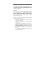
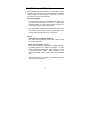
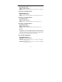
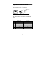
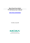
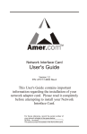
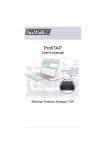
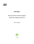
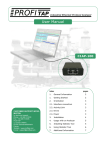
FCC Class A Appliance
This equipment generates and uses radio frequency energy. If
it is not installed and used properly in strict accordance with
the manufacturer‘s instructions, it may cause interference to
radio and television reception. It has been type-tested and
found to comply the specifications in sub-part J of Part 15 of
FCC Rules, which are designed to provide reasonable
protection against such interference in a residential installation.
There is no guarantee that interference will not occur in a
particular installation. If this equipment does cause interference
to radio or television reception which can be determined by
turning the equipment off and on, the user is encouraged to try
to correct the interference by one or more of the following
measures:
Re-orient the receiving antenna
!
!
!
Relocate the computing device with respect to
the
receiver
Move the computer away from the deceiver
Plug the computer into a different outlet so that
compute and receiver are on different
electrical circuits.
If necessary the user should consult the dealer or
an experienced radio or television technician for
additional suggestions.
The information in this manual is subject to
change without notice. All the brand names are
registered trademarks of their respective
companies.
1
Package Checklist
Carefully unpack the package and check its contents against
the checklist given below.
! 16
port 10/100 Smart Switch hub
manual
! AC power cord
! User
If any of these pieces are missing or damaged, please contact
your dealer immediately, if possible, retain the carton including
the original packing material, and use them against to repack
the product in case there is a need to return it to us for repair.
2
Contents
Introduction
Features and Specifications
Hardware Description
Front Panel
Rear Panel
Hardware Installation
Advance setup
Network Connection
10/100Mbps LAN Card to 10/100 Switch
100Mbps Hub to 10/100 Switch
10Mbps LAN Card to 10/100 Switch
10Mbps Hub to 10/100 Switch
Cascading 10/100 Switch
Switch Operation
Address Table
Learning
Forwarding & Filtering
Store-and-Forward
Auto MDI/MDI-X Negotiation
3
Introduction
The OfficeSwitch 16SR 10/100 Smart Switch Hub is
designed to allow simultaneous transmission of multiple
packets via an internal high-speed data channel. This means
that it can partition a network more efficiently than bridges or
routers in most environments. These 10/100 Switches are
highly reliable network switch and are the ideal device for
bridging Ethernet to Fast Ethernet workgroups or networks.
Simple and cost-effective, these Ethernet 10/100 Switch
support IEEE802.3u, IEEE802.3, IEEE802.1p 100Base-TX
and 10Base-T. It also supports Auto MDI/MDI-X function,
which means you can use any type of Cat.5 cable
(straight-through or Cross-over) cable for connecting to LAN
adapter or Uplink to other Hub, the Switch will auto-detect
the cable type.
In addition to fundamental functions of a Fast Ethernet
switch, there are many useful Smart features as Home
VLAN, Trunk, QoS are provided by LinkPro Office Switch
16RVT. User can obtain these advantages just by setting the
Mini DIP switch in real size of switch hub. The setup is very
easy and quickly. Because there are some EPROM’s
memory resident in the device used to keep the
configuration data, and during start-up or device reset, the
device will read these data to initialize system, users may
use this anytime to change their system and retain their
preference.
The front panel of the 10/100 Switch provides LEDs for easy
recognition of the switch operation status and for
troubleshooting. These LEDs display the power status for
the system and link, speed, full-duplex, also Trunking status.
4
Features and Specifications
Features:
"
16-port 10/100Mbps Smart Switch
"
Complies with the IEEE802.3 Ethernet and IEEE802.3u
"
Fast Ethernet standard
3.2Gbps Switching Fabric - Provides
Wire-Speed Performance On All Ports
"
Features
Store-and-Forward
mode
with
non-blocking
wire-speed
filtering and forwarding rates
"
Full/Half-Duplex capability on every TX ports, total
bandwidth is up to 200Mbps/port
"
Automatic source address learning and aging
"
Support up to 8,192 MAC address table
"
Support 4Mbit memory buffers
"
IEEE802.3x compliant full-duplex flow control
"
IEEE802.1p QoS function
"
Runt and CRC Filtering eliminates erroneous packets to
optimize the network bandwidth
"
Support to handle up to 1536 bytes packet
"
LED indicators for simple diagnostics and management
"
Support Auto MDI/MDI-X function
"
Support Port-base Home VLAN.
"
Support Port-base Trunking, upto 4 Trunk groups
"
Internal Switching power supply
"
Plug and Play
5
Specifications:
Model
Standard
Compliance
10/100Mbps
Switching
Ports
LEDs
MAC address
Memory buffer
Dimensions
(L x W x H)
Weight
Power Input
Power
Consumption
Operating
Temperature
Operating
Humidity
Electromagneti
c Compatibility
SH-9216SR
16 Ports 10/100 Smart Switch
IEEE 802.3, 802.3u, 802.1p
IEEE 802.3x
16
Power ,10/100Mbps speed
Link/Active, Half/Full duplex,Trunk status
8,192
4Mbit
260 x 145 x 48
mm
1450g
100-240 VAC 50-60Hz
10 W Max.
32 ~ 170 degrees F
(0 ~ 70 degrees C)
< 95%
(non-condensing)
FCC Part 15 Class A
CE
6
Hardware Description
This section describes the hardware features of the 16 port
OfficeSwitch16SR 10/100 Smart Switch. For easier
management and control of the switch, familiarize yourself
with its display indicators, and ports. Front panel illustrations
in this chapter display the unit LED indicators. Before
connecting any network device to the hub, read this chapter
carefully.
Front Panel
The unit front panel provides a simple interface monitoring
the 10/100 Switch.
7
LED indicators
LED Function Color
Description
POWER
Green
Lit: Power on
Link/Act
Green
Lit: Indicates the port that is
properly connected a power-on
adapter.
Blinking: It blinks when the port
is forwarding or receiving a
packet.
100M
Green
Lit: 100Mbps
FDX
Green
Lit: Full-Duplex
Unlit:10Mbps
Unlit: Half-Duplex
Blinking: Collision
Trunk LED 1
Green
Lit: Trunk group 1 active
(Port 1,2,3,4 )
Blinking: Trunk group 1 fault
Trunk LED2
Green
Lit: Trunk group 2 active
(Port 5,6,7,8 )
Blinking: Trunk group 2 fault
Trunk LED3
Green
Lit: Trunk group 3 active
(Port 9,10,11,12 )
Blinking: Trunk group 3 fault
Trunk LED 4
Green
Lit: Trunk group 4 active
(Port 13,14,15,16)
Blinking: Trunk group 4 fault
8
Rear Panel :
The rear panel of the 16 ports 10/100 Smart switch
contains the AC power receptacle and the Mini
DIPswitch for configures the Smart function of Switch
Hub.
The following sections describe the different components of
the rear panel.
Power Receptacle
Plug in the AC power cord into this receptacle to supply
power to the 10/100 Smart Switch.
Mini DIPswitches
There are 10 pcs of Mini DIPswitch which marked as
1,2,3,4,5,6,7,8,9,10 and all on upper “OFF” position
( default setting),
9
Hardware Installation
This chapter describes the installation procedure of the
10/100 Switch. Discussions include installation location,
connecting power, connecting network cables, and
cascading 10/100 Switch.
Install Site
You have the option to install the 10/100 Switch on a table.
When installing, choose a sturdy, level surface in a
ventilated area that is dust free and away from heat vents,
warm air exhaust from other devices and direct sunlight.
Avoid proximity to large electric motors or other
electromagnetic equipment.
Observe the following guidelines when choosing a good
location for the 10/100 Switch:
"
"
"
"
"
"
The surface must support at least 2kg for Linkpro
OfficeSwitch 16SR series.
Temperature ranges from 32 to 170 degrees F (0 to
70 degrees C).
Humidity should be less than 95%, non-condensing.
Ventilation space should be 2 inches above and on
each side, and 5 inches at the rear.
Site should not exceed the electromagnetic field
(RFC) standards for IEC 801-3, Level 2 (3V/M) field
strength.
100 to 240 VAC, 50/60Hz power outlet should be
within 6 feet of the device.
10
Installation on a Tabletop
When installing the 10/100 Switch on a table. Allow enough
ventilation space between the 10/100 Switch and the objects
around it (that is, at least 2 inches on each side, 5 inches at
the rear and 2 inches above the unit).
Connecting power
The OfficeSwitch 16SR 10/100 Smart Switch features an
AC power cord that makes connection to various input
voltages possible. Use the power cord with the device to
connect power to the 10/100 Smart Switch.
The OfficeSwitch 16SR series 10/100 Smart Switch does
not include a power switch; connecting the power cord to
a power outlet will right away turn on the device.
Notice:
Cable distance for Ethernet Switching
The cable distance between Switch and hub/PC should
not exceed 100 meter.
Make sure the wiring is correct
It can be used Category 3/4/5 cable in 10 Mbps operation.
To reliably operate your network at 100Mbps, you must
use an Unshielded Twisted-Pair (UTP) Category 5 cable,
or better Data Grade cabling. While a Category 3 or 4
cables may initially seem to work, it will soon cause data
loss.
All kinds of hub/PC can connect to 10/100Nway switch by
using straight-through wires.
11
Uplink Port
The OfficeSwitch 16SR series 10/100 Smart switch all
ports support Auto MDI/MDI-X function, It will auto-detect
the cable type when it plug into Switch, and it means all
ports can be use as Uplink port, and no need to use a
cross-over cable for uplink to other 10/100 switch.
Make sure the wiring is correct
It can be used Category 3/4/5 cable in 10 Mbps operation.
To reliably operate your network at 100Mbps, you must
use an Unshielded Twisted-Pair (UTP) Category 5 cable,
or better Data Grade cabling. While a Category 3 or 4
cables may initially seem to work, it will soon cause data
loss.
All kinds of hub/PC can connect to 10/100Nway switch by
using straight-through wires.
12
Advance Setup
The OfficeSwitch 16SR features Smart features function, all
the advance features can be easy setting by a group of mini
DIPswitch.
Notice: You need to power off the Switch before you
change the configuration.
Port base priority QoS function:
Mini DIPswitch [1,2] :
[OFF:OFF] : Disable QoS function. (default)
[OFF:ON]: Port 1,2 as high priority (2 ports)
[ON:OFF]: Port 1,2,3,4 as high priority (4 ports).
[ON:ON]: Port 1 - 8 as high priority (8 ports).
802.1p VLAN Tag priority base QoS:
Mini DIPswitch [3] :
[OFF] : Disable (default)
[ON]: Enable, Priority 0~3 = low priority,
4~7=high priority.
TCP/IP TOS/DS (Diffentiated Service) base QoS :
Mini DIP switch [4] :
[OFF] : Disable (default)
[ON]: Enable, High Priority, if TOS/DS[0:5] = (EF) “101110”;
(AF) “001010”, “010010”, “011010”,
“100010”; (Network Control) “11x000”
Low Priority, if TOS/DS = other codepoint
values
13
Port base Trunking group 4:
Mini DIP switch [5] :
[OFF] : Disable (default)
[ON]: Enable Port Trunk 4, which consists of ports 13,14,15,16.
Port base Trunking group 3:
Mini DIP switch [6] :
[OFF] : Disable (default)
[ON]: Enable Port Trunk 4, which consists of ports 9,10,11,12.
Port base Trunking group 2:
Mini DIPswitch [7] :
[OFF] : Disable (default)
[ON]: Enable Port Trunk 4, which consists of ports 5,6,7,8.
Port base Trunking group 1:
Mini DIPswitch [8] :
[OFF] : Disable (default)
[ON]: Enable Port Trunk 4, which consists of ports 1,2,3,4.
NOTICE :
If any physical port of a trunk group has a link down, then all of
the physical ports of the trunk group will be treated as having a
link down and the Trunk LED will blinking to indicate that a
fault condition has happened on this trunk group.
Port VLAN configuration :
Mini DIPswitch [9,10] :
[OFF;OFF] : Disable (default)
[ON:ON]: Enable 15 VLANs ( port 1~15), with 1 overlapping
port (port 16)
[ON:OFF]: Enable 14 VLANs ( port 1~14), with 2 overlapping
port (port 15,16)
14
Network connections
100Mbps LAN adapter to 10/100 Switch
Plug one end of the Category 5 straight-through UTP
Cable into any one port of the 10/100 Switch, and the other
end of this cable into the RJ-45 of 100Mbps Fast Ethernet
Adapter in the server or PC. The cable length between
these 2 connecting points should not exceed 100 meter.
100Mbps Hub to 10/100 Switch
Plug one end of the Category 5 straight-through UTP Cable
into any port of the 10/100 Switch, the other end of this cable
into "Uplink" port of the 100Mbps Fast Ethernet Hub, The
cable length between these 2 connecting points should not
exceed 100 meter.
10Mbps LAN adapter to 10/100 Switch
Plug one end of the Category 3 or 5 straight-through UTP
Cable into any one port of the 10/100 Switch, and the other
end of this cable into the RJ-45 of 10Mbps Ethernet Adapter
in the server or PC. The cable length between these 2
connecting points should not exceed 100 meter.
10Mbps Hub to 10/100 Switch
Plug one end of the Category 3 or 5 straight-through UTP
Cable into any port of the 10/100 Switch, the other end
of this cable into "Uplink" port of the 10Mbps Ethernet Hub,
The cable length between these 2 connecting points
should not exceed 100 meter.
15
Cascading 10/100 Switch
Since the 10/100 Switch are not purely repeaters, the
10BASE-T and 100BASE-TX rules on the maximum number
of repeaters that can be cascaded together (that is, four for
10BASE-T and two for 100BASE-TX) do not apply to these
devices. However, According to IEEE 802.3u switching
architecture, the idea maximum cascading number of 10/100
Switch is no limitation, but it will be depend on the
delay-time of teleportation and driven capability of PHY
components, because the packet inside switch was
forwarded by store-and-forward method, more cascading (or
more length between two switch) will cause much packet
delay-time.
Connection
1.
Plug one end of the Category 5 straight-through UTP
Cable into any port of SH-9216R switch , the other end
of this cable into any normal port of the other 10/100
Switch, The cable length between these 2 connecting
points should not exceed 100 meter.
16
Switch Operation
Address Table
The OfficeSwitch 16SR series 10/100 switch is implemented
with an address table. This address table composed of many
entries. Each entry is used to store the address information
of some node in network, including MAC address, port no,
etc. This information comes from the learning process of
Ethernet Switching.
Learning
When one packet comes in from any port. The 10/100
Switch will record the source address, port no. and the other
related information in address table. This information will be
used to decide either forwarding or filtering for future
packets.
Forwarding & Filtering
When one packet comes from some port of the Ethernet
Switching, it will also check the destination address besides
the source address learning. The 10/100 Switch will lookup
the address-table for the destination address. If not found,
this packet will be forwarded to all the other ports except the
port which this packet comes in. And these ports will transmit
this packet to the network it connected. If found, and the
destination address is located at different port from this
packet comes in, the 10/100 Switch will forward this packet
to the port where this destination address is located
according to the information from address table. But, if the
destination address is located at the same port with this
packet comes in, when this packet will be filtered. Thereby
increasing the network throughput and availability.
17
Store-and-Forward
Store-and-Forward is one type of packet-forwarding
techniques. A Store-and-Forward 10/100 Switch stores
the incoming frame in an internal buffer, do the complete
error checking before transmission.
Therefore, no error packets occurrence, it is the best choice
when a network needs efficiency and stability.
The 10/100Nway Switch scans the destination address from
the packet-header, searches the routing table provided for
the incoming port and forwards the packet, only if required.
The fast forwarding makes the switch attractive for
connecting servers directly to the network, thereby
increasing throughput and availability. However, the switch is
most commonly used to segment existing hubs, which nearly
always improves overall performance. A Ethernet 10/100
Switch can be easily configured in any Ethernet network
environment to significantly boost bandwidth using
conventional cabling and adapters.
Due to the learning function of the Ethernet switching, the
source address and corresponding port number of each
incoming and outgoing packet are stored in a routing table.
This information is subsequently used to filter packets whose
destination address is on the same segment as the source
address. This confines network traffic to its respective
domain, reducing the overall load on the network.
The 10/100 Switch performs "Store and forward" therefore,
no error packets occur. More reliably, it reduces the
re-transmission rate. No packet loss will occur.
18
Auto-Negotiation
The STP ports on both OfficeSwitch series 10/100 switch
have
built-in
“Auto-negotiation”.
This
technology
automatically sets the best possible bandwidth when a
connection is established with another network device
(usually at Power On or Reset). This is done by detect the
modes and speeds at the second of both device is
connected and capable of, Both 10Base-T and 100Base-TX
devices can connect with the port in either Half- or
Full-Duplex mode.
If attached device is :
10Mbps, no auto-negotiation
10Mbps, auto-negotiation
100Mbps, no auto-negotiation
100Mbps, auto-negotiation
The port will set to:
10Mbps
20Mbps(10Base,Full Duplex)
100Mbps
200Mbps(100Base,Full
Duplex)
Auto MDI/MDI-X Negotiation
Auto MDI/MDI-X function enables the Switch’s
transceiver to automatically detect and correct wrong
cable wiring problem. It means you can use either
straight- through cable or cross-over cable in any port of
the Switch for connect to LAN adapter or other
Hub/Switch.
19
Appendix A - Connector Pinouts
Pin arrangement of RJ-45 connectors
RJ-45 Connector and Cable Pins
The following table lists the pinout of 10/100BASE-T/TX
ports
Table : Connector Pin-Out
Pin
1
2
3
4
5
6
7
8
Regular Ports
Input Receive Data +
Input Receive Data Output Transmit Data +
NC
NC
Output Transmit Data NC
NC
20
Uplink port
Output Transmit Data +
Output Transmit Data Input Receive Data +
NC
NC
Input Receive Data NC
NC