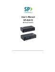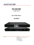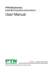
1
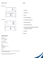
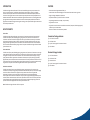
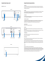
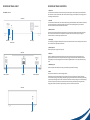
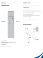
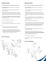
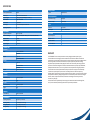
User Manual
PT-E-HIP
PT-E-HIP | User Manual
Contents
PT-E-HIP-TX | Transmitter
1.Introduction
2. How It Connects
3.Features
4. Transmitter Unit Panel Layout
PT-E-HIP-RX | Receiver
5. Transmitter Unit Panel Description
6. Receiver Unit Panel Layout
7. Receiver Unit Panel Description
8. Connecting and Operating the HDMI Over Gigabit Extender
with Push Button and LED Display
9. Specification
10.Warranty
ASKING FOR ASSISTANCE
Technical Support:
Telephone +49 5971 800 299 0
Fax
+49 5971 800 299 99
Technical Support Hours:
9:00 AM to 6:00 PM Monday thru Friday.
Write To:
PureLink GmbH
Hovesaatstr. 6 48432 Rheine/ Deutschland
http://www.purelink.de
[email protected]
Notice:
Product Features and Specifications may change without notice. This can include software, hardware, accessories,
packaging and any accompanying documentation.
Attention must be paid to specified network requirements for reliable system operation.
HDMI Over Gigabit Extender with Push Button and LED Display is a trademark Under License to HPC Technology Inc.
INTRODUCTION
FEATURES
The HDMI over Gigabit Ethernet Extender PT-E-HIP with IR sends HDMI signals over just one 100 Ohm Cat.6
cable- up to 100 metres away. The HDMI over Gigabit Extender supports HDMI 1.3b with Full HD 1080p
resolution. DVI-D Computer video can also be transmitted with a DVI-to-HDMI cable or adaptor (Audio is not
included in a DVI-D signal). Maximum screen resolution and system performance is entirely dependent on the
bandwidth and features made available to the HDMI over Gigabit Extender devices on the local Gigabit network.
• Flexible extension of high-bandwidth HDMI 1.3b
By using standard and widely available 100 Ohm Cat.6 cable wired to the 568A specification, the HDMI over
Gigabit Extender makes HDMI signal networking easier than larger, more expensive HDMI copper cable and more
robust than optical fiber cable.
• Audio and video are transmitted digitally over the 100Ohm Cat.6 cable for lower signal loss
• Single Link Range: 1080p/60 and 1920x1200.
• Compliant with HDMI 1.3b, HDCP 2.0 and DVI1.1 standards
• Supports digital video formats in 480p , 720p and 1080p
• Supports PCM 2 Ch audio
• Supports IR Pass thru function to control HDMI source devices (set-top box, DVD/BluRay player etc.)
in Receiver by its IR remote control
HOW IT CONNECTS
• Select source Device via IR remote control provided
Point to Point
The HDMI over Gigabit Ethernet Extender system consists of a Transmitter and a Receiver (sold separately).
The HDMI source (set-top box, DVD/BluRay player, gaming console, etc.) connects to the Transmitter unit.
The Receiver unit connects to the HDTV display in the same way. One 100 Ohm Cat.6 cable (up to 100 meters
long) links the Transmitter and Receiver. Power is applied to the Transmitter and Receiver with 5V DC power
supply (included). High Definition picture and Sound are then transmitted into the HDTV screen. HDMI Source
Device can also be controlled remotely using the built in IR repeater in the HDMI over Gigabit Ethernet Extender
System at Receiver side.
Transmitter Package Includes
(1) 1x PT-E-HIP-TX Transmitter
(2) 1x IR Emitter Cable
(3) 1x 5V DC Power Supply for Transmitter or Receiver
(4) 1x User Manual
Point to Multi-Point
The HDMI source (set-top box, DVD/BluRay player, gaming console, etc.) connects to a Transmitter unit via a high
quality HDMI cable. 100 Ohm Cat.6 cables (each up to 100 metres in length) link the Transmitters and Receivers
via a Gigabit Full Duplex network switch. The Receiver units connect to each of the HDTV displays via a high
quality HDMI cable. Power is applied to the Transmitters and Receivers with 5V DC power supply (included).
High Definition picture and Sound are then transmitted into the HDTV screens, provided each receiver unit is set
to the required source channel (remote control supplied). HDMI Source Devices can also be controlled remotely
using the built in IR repeater in the HDMI over Gigabit Ethernet Extender System at Receiver side.
Multi-Point to Multi-Point
The HDMI source devices (set-top boxes, DVDs/BluRay players, gaming consoles, etc.) each connect to a
Transmitter unit (16 Max) via a high quality HDMI cable. 100 Ohm Cat.6 cables (each up to 100 metres in length)
link the Transmitters and Receivers via a Gigabit Full Duplex network switch that must support IGMP
functionality. The Receiver units connect to each of the HDTV displays via a high quality HDMI cable.
Power is applied to the Transmitters and Receivers with 5V DC power supply (included). High Definition picture
and Sound are then transmitted into the HDTV screens, provided each receiver unit is set to the required source
channel (remote control supplied). HDMI Source Devices can also be controlled remotely using the built in IR
repeater in the HDMI over Gigabit Ethernet Extender System at Receiver side.
Note: The HDMI over Gigabit Extender is HDCP 2.0 compliant.
Receiver Package Includes
(1) 1x PT-E-HIP-RX Receiver
(2) 1x IR Receiver Cable
(3) 1x Remote Control
(4) 1x 5V DC Power Supply for Transmitter or Receiver
(5) 1x User Manual
TRANSMITTER UNIT PANEL LAYOUT
TRANSMITTER UNIT PANEL DESCRIPTION
1. Power LED
PT-E-HIP-TX | Transmitter
This LED indicator will activate once the included 5V DC power adapter has been properly connected between
the Transmitter unit and a power socket. Note: the LED will blink during the initial power up time during which it
is loading the device firmware.
Front Panel
2. Link LED
This LED indicator will flash once Cat 6. cable has been properly connected between the Transmitter and Receiver
unit. Once both devices are connected and powered up this LED will stop flashing and stay on to indicate
successful connection between Transmitter and Receiver.
3. Led Display
The LED Display is designed to give identity to transmitter and its input display. User can select identity from
1 to 16 via push buttons as indicated below.
Link LED
LED Display
Power LED
Push Button
Down
Push Button
Up
4. Push Button – Up/Down
It is possible (when network bandwidth allows) to have up to 16 transmitters and corresponding source devices
running at once. Push button up/down is designed to define which of these “channels” is to be used.
System installers can change definition of source channel by pressing push button up/down.
5. Power Input Port
Connect 5V DC power supply to this input port.
Back Panel
6. RJ45 Port
Connect a 100Ohm Cat.6 cable between this output port and the RJ45 input port on Receiver unit or Gigabit
network switch.
Note: for best performance we encourage the use of Stranded CAT6A shielded cable STP (750Mhz), as a minimum
though please ensure CAT6 UTP (550Mhz) cable is used or poor performance may result.
7. HDMI Input Port
Connect one HDMI cable between this port and HDMI output port of the source device
(DVD, Set-top box, blue-ray DVD)
Power Input Port
RJ45 Port
HDMI Input Port
IR Emitter Port
8. IR Emitter Port
Connect an IR Emitter Cable to this IR port and stick IR emitter module on the IR receiver zone of HDMI source
(set-top box, DVD player and Blue ray DVD Player).
Insert the IR Emitter Cable to this IR port and place the connected IR emitter module on the IR receiver zone of
HDMI source (set-top box, DVD player or BluRay Player). Note: Some devices are very particular about IR emitter
placement; success can be achieved by experimenting with emitter location prior to adhering the emitter to the
device.
Side Panel
9. Reset
Please press this button once it has connecting problem.
Occasionally like many network devices (routers, modems etc) it may be necessary to reset the Transmitter.
This can be done by using a small tool (eg: toothpick) to gently press and hold the reset switch for approximately
3 seconds. Upon releasing the switch the unit will reboot and restore its factory settings. Source channel settings
will remain as previously set and normal function should resume shortly. Alternatively removing the Power
Supply from the Power Input Port for approximately 5 minutes will achieve the same result.
Reset
RECEIVER UNIT PANEL LAYOUT
RECEIVER UNIT PANEL DESCRIPTION
1. Power LED
PT-E-HIP-RX | Receiver
This LED indicator will activate once the included 5V DC power adapter has been properly connected between
the Transmitter unit and a power socket. Note: the LED will blink during the initial power up time during which it
is loading the device firmware.
Front Panel
2. Link LED
This LED indicator will flash once Cat 6. cable has been properly connected between the Transmitter and Receiver
unit. Once both devices are connected and powered up this LED will stop flashing and stay on to indicate
successful connection between Transmitter and Receiver.
3. IR Extender Port
Please connect the provided IR Receiver cable to this port. This allows the supplied remote control to function;
the source device can now also be controlled from the location of this receiver unit by way of its original
IR remote control or a universal type IR remote control.
Link LED
Power LED
IR
Extender Port
LED Display
4. LED Display
The LED Display is designed to identify which source device channel the receiver is set to display. User can select
source channel via the provided remote control.
5. Power Input Port
Connect 5V DC power supply to this input port.
Back Panel
6. RJ45 Port
Connect a 100Ohm Cat.6 cable between this input port and the RJ45 output port from Transmitter unit or
Gigabit network switch. Note: for best performance we encourage the use of Stranded CAT6A shielded cable
STP (750Mhz), as a minimum though please ensure CAT6 UTP (550Mhz) cable is used or poor performance may
result.
7. HDMI output port
Connect one HDMI cable between this output port and HDMI input port of HDTV display.
8. Reset
Power Input Port
RJ45 Port
HDMI Output Port
Please press this button once it has connecting problem.
Occasionally like many network devices (routers, modems etc) it may be necessary to reset the Transmitter.
This can be done by using a small tool (eg: toothpick) to gently press and hold the reset switch for approximately
3 seconds. Upon releasing the switch the unit will reboot and restore its factory settings. Source channel settings
will remain as previously set and normal function should resume shortly. Alternatively removing the Power
Supply from the Power Input Port for approximately 5 minutes will achieve the same result.
Side Panel
Reset
REMOTE CONTROL
CONNECTING AND OPERATING
PANEL LAYOUT & DISCRIPTION
How to Connect HDMI Over Gigabit with Push Button and LED Display | One Source to One Display
1. Connect one HDMI Cable between the HDMI output port of source device and the HDMI input port
of Transmitter unit (3 Metres Max)
2. Connect one HDMI Cable between the HDMI input port of display device and the HDMI output port
of Receiver unit. (3 Metres Max)
Front Panel
3. Connect one 100 Ohm Cat.6 cable between the RJ45 port of Transmitter unit and RJ45 port of Receiver unit.
Note: CAT.6 is to be no longer than 100 meters in length and should not run parallel to mains power cables.
4. Connect 5V DC power supplies to both Transmitter and Receiver unit.
5. Power on the display device first and then the source device.
6. Use remote control to select the related channel that the dip switch has been set to on the transmitter.
Please refer to Appendix A for the link diagram.
Note:
1.
Press to switch source
channel numerically
IR Function is able to receive signal from the IR remote control of your source device
and the remote control supplied with the Receiver unit.
Press to switch source
channel numericall
Please refer to following diagram:
1. Downward Selection Button
This button allows user to switch to a lower source channel (from source 16 to source 1).
Hold this button down to change quickly.
2. Upward Selection Button
This button allows user to switch to a higher source channel
CONNECTING AND OPERATING
CONNECTING AND OPERATING
How to Connect HDMI Over Gigabit with Push Button and LED Display | One Source to Many Displays
How to Connect HDMI Over Gigabit with Push Button and LED Display | Many Sources to Many Displays
1. Connect one HDMI Cable between the HDMI output port of source device and the HDMI input port
of Transmitter unit (3 Metres Max)
1. Connect one HDMI Cable between the HDMI output port of source device and the HDMI input port
of Transmitter unit (3 Metres Max)
2. Connect one HDMI Cable between the HDMI input port of display device and the HDMI output port
of Receiver units. (3 Metres Max)
2. Connect one HDMI Cable between the HDMI input port of display device and the HDMI output port
of Receiver unit. (3 Metres Max)
3. Connect one 100 Ohm Cat.6 cable between the RJ45 port of transmitter and input port of a Full Duplex
Gigabit Ethernet switch (consult your network specialist for advice on choosing a suitable Gigabit switch).
Note: CAT.6 is to be no longer than 100 meters in length and should not run parallel to mains power cables.
3. Connect one 100 Ohm Cat.6 cable between the RJ45 port of each transmitter and the input ports of a Full
Duplex Gigabit Ethernet switch (consult your network specialist for advice on choosing a suitable Gigabit
switch). Note: CAT.6 is to be no longer than 100 meters in length and should not run parallel to mains power
cables.
4. Connect one 100 Ohm Cat.6 cable between the output ports of the Full Duplex Gigabit Ethernet switch
and RJ45 port of each Receiver unit. Note: CAT.6 is to be no longer than 100 meters in length and should
not run parallel to mains power cables.
5. Connect 5V DC power supplies to both Transmitter and Receiver unit.
6. Power on the Display device first and then the source device.
7. Use the supplied remote control to select the related channels that have been set to on the transmitters.
Note:
1.IR Function is able to receive signal from the IR remote control of your source devices
(or Universal Remote Control) and the remote control supplied with the Receiver unit.
2.As the Transmitter units can support over 200 IP address for different receiver units, it can connect
up to 200 Receiver units at once, this function however is completely limited by the Gigabit LAN’s
Bandwidth capacity. At times it may be necessary to reduce the output resolution of your source devices
to compensate for lower than required bandwidth availability within the network.
One Source to Many Displays:
4. Connect one 100 Ohm Cat.6 cable between the output ports of the Full Duplex Gigabit Ethernet switch
and RJ45 port of each Receiver unit. Note: CAT.6 is to be no longer than 100 metres in length and should not
run parallel to mains power cables.
5. Connect 5V DC power supplies to all Transmitter units and Receiver units.
6. Users can select a different source channel for each Transmitter by push button up/down on each transmitter
unit. They can then select the required source device they would like to display on each screen by using the
supplied remote control with each Receiver unit to select the associated channel. Allowing for dynamic
selection of any of the connected source devices from any of the connected display devices.
Note:
1. IR Function is able to receive signal from the IR remote control of your Source Device and the IR remote
control Supplied with the Receiver unit.
2.
As the Transmitter units can support over 200 IP address for different receiver units, it can connect
up to 200 Receiver units at once, this function however is completely limited by the Gigabit LAN’s Bandwidth
capacity. At times it may be necessary to reduce the output resolution of your source devices to compensate
for lower than required bandwidth availability within the network.
3. Users can connect at most 16 Transmitters to the system.
4. Please note that the Ethernet switch should be a Full Duplex Gigabit Ethernet switch that supports
IGMP functions.
Please refer to following diagram:
SPECIFICATION
SPECIFICATION
REMOTE CONTROL
Video Amplifier Bandwidth
225 MHz
Video Output
1080p/60 and 1920x1200 max. res
Input DDC Signal
5 Volts p-p (TTL); Input Video Signal: 1.2 Volts p-p
HDMI Connector
Type A, 19 Pin Female
Link Connector
RJ45 Shielded
Power Supply
5V DC Power Consumption: 10 Watts max.
SAFETY
Operating Temperature
0°C - 40°C
Certificate
FCC, CE, RoHS
Power Adapter
UL, CE, CSA, CEC, RoHS, SAA
PERFORMANCE
Infrared
IR Remote (Front)
POWER REQUIREMENTS
External Power Supply
[email protected]
Power Consumption
10 Watts (Max.)
Supported HD Resolutions
480p, 720p, 1080p
ACCESSORIES
Maximum Cable Range
Input: 3 Metres Max (HDMI Cable) Outputs: 100 Metres Max (Cat.6 Cable)
AC Power Adapter X 1
Video Bandwidth
6.95Gbps
IR Emitter Cable X 1
Input Video Signal
1.2 Volts P-P
IR Receiver Cable X 1
Input DDC Signal
5.0 Volts P-P
Instruction Manual X 1
I/O CONNECTORS
Transmitter
Inputs
1 HDMI-A 19PIN Socket
1 5V DC Jack
Outputs
1 RJ45 Jack
1 3.5mm Jack-IR Emitter
Receiver
Inputs
1 RJ45 Jack
1 IR Receiver Module
1 5V DC Jack
Outputs
1 HDMI-A 19PIN Socket
MECHNICAL
Transmitter
Dimensions (H-W-D)
162.3x142.35x30mm
Weight
0.7kg
Receiver
Dimensions (H-W-D)
162.3x142.35x30mm
Weight
0.7kg
WARRANTY
Limited Warranty
1 Year Parts and Labor
ENVIRONMENTAL
Operating Temperature
+0 to +40° C (+32° to 104° F)
Operating Humidity
10% to 85% (Non-condensing)
Storage Temperature
-20° to +60° (+20° to +140° F)
Storage Humidity
10% to 85% (Non-condensing)
WARRANTY
LIMITED WARRANTY – With the exceptions noted in the next paragraph and those required by Law,
PureLink GmBH warrants the original purchaser that this device will be free from defects in materials and
workmanship for a period of one year from the date of purchase. Should this product be proven defective within
this warranty period, PureLink GmbH, at its discretion, will repair or replace this product free of charge.
Any defective parts replaced become the property of PureLink GmbH. This warranty does not apply to those
products which have been damaged due to accident, unauthorized alterations, improper repair, modifications,
inadequate maintenance and care, or use in any manner for which the product was not originally intended.
PureLink GmbH makes no other representation of warranty as to fitness for the purpose or merchantability
or otherwise in respect of any of the products sold. The liability of PureLink GmbH with respect to any
defective products will be limited to the repair or replacement of such products. In no event shall PureLink GmbH
be responsible or liable for any damage arising from the use of such defective products whether such damages
be direct, indirect, consequential or otherwise, and whether such damages are incurred by the reseller,
end-user or any third party.
PureLink GmbH holds no responsibility for faults arising due to conditions outside of manufacturing faults,
such as (but not limited to) connected equipment faults or poor network performance.
PureLink GmbH
Hovesaatstraße 6
D - 48432 Rheine
Germany
Telefon: 0049 (0)5971-800 299-0
Fax:
0049 (0)5971-800 299-99
E-mail:[email protected]
Internet:www.purelink.de
© 2013 PureLink GmbH. All rights reserved.
All trade names are registered trademarks of
respective manufactures listed.
HDMI is a trademark of HDMI Licensing LLC.