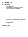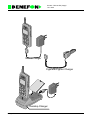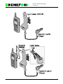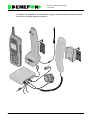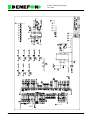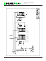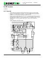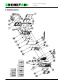
1
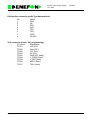
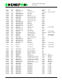
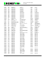
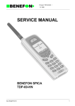
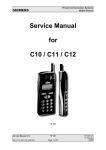
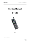
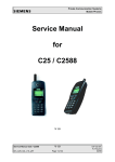
Product: TGP-60-EU (Vega) /
15.1.1999
SERVICE MANUAL
BENEFON VEGA
TGP-60-EU
GP_60UGB.TOC
1
Product: TGP-60-EU (Vega) /
15.1.1999
TGP-60-EU
1.0 PRODUCT FEATURE DESCRIPTION . . . . . . . . . . . . . . . . . . . . . 1 - 1
1.1 Network standard . . . . . . . . . . . . . . . . . . . . . . . . . . . . . . . . . . . . . 1 - 1
1.2 Physical dimensions . . . . . . . . . . . . . . . . . . . . . . . . . . . . . . . . . . . 1 - 1
1.3 Display . . . . . . . . . . . . . . . . . . . . . . . . . . . . . . . . . . . . . . . . . . . . . 1 - 1
1.4 Abbreviated dialling memory . . . . . . . . . . . . . . . . . . . . . . . . . . . . . 1 - 1
1.5 Recent Calls memory . . . . . . . . . . . . . . . . . . . . . . . . . . . . . . . . . . 1 - 1
1.6 Clock functions . . . . . . . . . . . . . . . . . . . . . . . . . . . . . . . . . . . . . . . 1 - 2
1.7 Additional network dependant features . . . . . . . . . . . . . . . . . . . . . 1 - 2
1.8 SIM card . . . . . . . . . . . . . . . . . . . . . . . . . . . . . . . . . . . . . . . . . . . . 1 - 2
1.9 Power consumption . . . . . . . . . . . . . . . . . . . . . . . . . . . . . . . . . . . . 1 - 2
1.10 Other functions . . . . . . . . . . . . . . . . . . . . . . . . . . . . . . . . . . . . . . 1 - 2
1.11 Accessories . . . . . . . . . . . . . . . . . . . . . . . . . . . . . . . . . . . . . . . . . 1 - 3
1.12 Manufacturer . . . . . . . . . . . . . . . . . . . . . . . . . . . . . . . . . . . . . . . . 1 - 3
1.13 PRODUCT FAMILY . . . . . . . . . . . . . . . . . . . . . . . . . . . . . . . . . . 1 - 4
2.0 OWNER’S MANUAL . . . . . . . . . . . . . . . . . . . . . . . . . . . . . . . . . . 2 - 1
3.0 CAR KIT . . . . . . . . . . . . . . . . . . . . . . . . . . . . . . . . . . . . . . . . . . . . 3 - 1
3.0.1 Antenna . . . . . . . . . . . . . . . . . . . . . . . . . . . . . . . . . . . . . . . . . . . 3 - 1
3.0.2 Phone Holder KDS-60 . . . . . . . . . . . . . . . . . . . . . . . . . . . . . . . . 3 - 1
3.0.3 Microphone . . . . . . . . . . . . . . . . . . . . . . . . . . . . . . . . . . . . . . . . 3 - 1
3.0.4 Cable . . . . . . . . . . . . . . . . . . . . . . . . . . . . . . . . . . . . . . . . . . . . . 3 - 1
3.0.5 External Handset HDS-50 . . . . . . . . . . . . . . . . . . . . . . . . . . . . . 3 - 2
3.0.6 Car Box UDH-60 . . . . . . . . . . . . . . . . . . . . . . . . . . . . . . . . . . . . 3 - 2
3.0.7 Hf Speaker . . . . . . . . . . . . . . . . . . . . . . . . . . . . . . . . . . . . . . . . . 3 - 2
4.0 LOCAL SERVICE MODE . . . . . . . . . . . . . . . . . . . . . . . . . . . . . . . 4 - 1
4.1 SERVICE EQUIPMENT . . . . . . . . . . . . . . . . . . . . . . . . . . . . . . . . 4 - 1
4.1.1 General . . . . . . . . . . . . . . . . . . . . . . . . . . . . . . . . . . . . . . . . . . . 4 - 1
4.1.2 Required equipment . . . . . . . . . . . . . . . . . . . . . . . . . . . . . . . . . . 4 - 1
4.1.3 Power source . . . . . . . . . . . . . . . . . . . . . . . . . . . . . . . . . . . . . . . 4 - 2
4.2 GSERV . . . . . . . . . . . . . . . . . . . . . . . . . . . . . . . . . . . . . . . . . . . . . 4 - 3
4.2.1 General . . . . . . . . . . . . . . . . . . . . . . . . . . . . . . . . . . . . . . . . . . . 4 - 3
4.2.2 Installation . . . . . . . . . . . . . . . . . . . . . . . . . . . . . . . . . . . . . . . . . 4 - 3
4.2.3 Starting GSERV . . . . . . . . . . . . . . . . . . . . . . . . . . . . . . . . . . . . . 4 - 3
GP_60UGB.TOC
2
Product: TGP-60-EU (Vega) /
15.1.1999
4.2.4 Troubleshooting . . . . . . . . . . . . . . . . . . . . . . . . . . . . . . . . . . . . . 4 - 3
4.2.5 Remote control of measurement equipment . . . . . . . . . . . . . . . 4 - 4
4.3 SERVICE MODE COMMANDS . . . . . . . . . . . . . . . . . . . . . . . . . . 4 - 5
4.3.1 Local mode . . . . . . . . . . . . . . . . . . . . . . . . . . . . . . . . . . . . . . . . . 4 - 5
4.3.2 GSM mode . . . . . . . . . . . . . . . . . . . . . . . . . . . . . . . . . . . . . . . . . 4 - 5
4.3.3 Service . . . . . . . . . . . . . . . . . . . . . . . . . . . . . . . . . . . . . . . . . . . . 4 - 5
4.3.4 Tuning . . . . . . . . . . . . . . . . . . . . . . . . . . . . . . . . . . . . . . . . . . . . 4 - 5
4.3.5 Memory and settings . . . . . . . . . . . . . . . . . . . . . . . . . . . . . . . . . 4 - 6
4.3.6 Keyboard . . . . . . . . . . . . . . . . . . . . . . . . . . . . . . . . . . . . . . . . . . 4 - 6
4.3.7 About . . . . . . . . . . . . . . . . . . . . . . . . . . . . . . . . . . . . . . . . . . . . . 4 - 6
4.4 TUNING INSTRUCTIONS . . . . . . . . . . . . . . . . . . . . . . . . . . . . . . 4 - 7
4.4.1 General . . . . . . . . . . . . . . . . . . . . . . . . . . . . . . . . . . . . . . . . . . . 4 - 7
4.4.2 Base frequency . . . . . . . . . . . . . . . . . . . . . . . . . . . . . . . . . . . . . 4 - 7
4.4.3 TX power . . . . . . . . . . . . . . . . . . . . . . . . . . . . . . . . . . . . . . . . . . 4 - 7
4.4.4 RX RSSI . . . . . . . . . . . . . . . . . . . . . . . . . . . . . . . . . . . . . . . . . . . 4 - 8
4.4.5 A/D converter calibration . . . . . . . . . . . . . . . . . . . . . . . . . . . . . . 4 - 8
4.4.6 Contrast . . . . . . . . . . . . . . . . . . . . . . . . . . . . . . . . . . . . . . . . . . . 4 - 9
4.4.7 Enable/Disable tuning values . . . . . . . . . . . . . . . . . . . . . . . . . . . 4 - 9
5.0 TECHNICAL DESCRIPTION . . . . . . . . . . . . . . . . . . . . . . . . . . . . 5 - 1
5.0.1 Block diagram of the product . . . . . . . . . . . . . . . . . . . . . . . . . . . 5 - 1
5.0.2 A technical explanation . . . . . . . . . . . . . . . . . . . . . . . . . . . . . . . 5 - 1
5.1 Charging . . . . . . . . . . . . . . . . . . . . . . . . . . . . . . . . . . . . . . . . . . . . 5 - 2
5.2 HW and SW version numbering . . . . . . . . . . . . . . . . . . . . . . . . . . 5 - 2
5.2.1 Hardware version . . . . . . . . . . . . . . . . . . . . . . . . . . . . . . . . . . . . 5 - 2
5.2.2 Software version . . . . . . . . . . . . . . . . . . . . . . . . . . . . . . . . . . . . 5 - 2
5.3 Logic/audio module . . . . . . . . . . . . . . . . . . . . . . . . . . . . . . . . . . . . 5 - 3
5.3.1 Audio Controls . . . . . . . . . . . . . . . . . . . . . . . . . . . . . . . . . . . . . . 5 - 4
5.3.2 Connectors . . . . . . . . . . . . . . . . . . . . . . . . . . . . . . . . . . . . . . . . . 5 - 5
5.3.3 Parts list OA1800 . . . . . . . . . . . . . . . . . . . . . . . . . . . . . . . . . . . . 5 - 8
5.4 RF-module . . . . . . . . . . . . . . . . . . . . . . . . . . . . . . . . . . . . . . . . .5 - 21
5.4.1 General . . . . . . . . . . . . . . . . . . . . . . . . . . . . . . . . . . . . . . . . . .5 - 21
5.4.2 Receiver . . . . . . . . . . . . . . . . . . . . . . . . . . . . . . . . . . . . . . . . . .5 - 22
5.4.3 Transmitter . . . . . . . . . . . . . . . . . . . . . . . . . . . . . . . . . . . . . . . .5 - 22
5.4.4 Synthesizer . . . . . . . . . . . . . . . . . . . . . . . . . . . . . . . . . . . . . . .5 - 22
5.4.5 Power supply and power switching. . . . . . . . . . . . . . . . . . . . . .5 - 22
GP_60UGB.TOC
3
Product: TGP-60-EU (Vega) /
15.1.1999
5.4.6 Antenna and antenna connector . . . . . . . . . . . . . . . . . . . . . . .5 - 23
5.4.7 Parts list OY1800 . . . . . . . . . . . . . . . . . . . . . . . . . . . . . . . . . . .5 - 24
5.5 MECHANICS . . . . . . . . . . . . . . . . . . . . . . . . . . . . . . . . . . . . . . . . 5 - 36
GP_60UGB.TOC
4
Product: TGP-60-EU (Vega) /
15.1.1999
1.0 PRODUCT FEATURE DESCRIPTION
1.1 Network standard
GSM 900 phase 1 class 4 handportable (2W) with supporting Full Rate speech
coding.
Additionally Benefon Vega supports some phase 2 features.
No data services are supported.
1.2 Physical dimensions
Maximum dimensions without antenna are 56 x 145 x 23. Volume of the phone
159 cc.
Weight of the phone is around 190 g.
1.3 Display
Clear and easy to read full graphical 30x36 mm LCD. The display has 8
symbols consisting of 23 indicators. Text area has altogether 33x95 pixels.
Minimum of 4x16 characters can be displayed simultaneously.
1.4 Abbreviated dialling memory
- extremely simple key strokes to call to abbreviated dialling numbers
- for each number an alphanumeric string of 20 characters can be attached.
This string is displayed if CLIP service notices an incoming call from saved
number.
- memory scroll and recall in an alphabetical order
1.5 Recent Calls memory
- last dialled number memory for 15 entries, extremely simple key sequence to
call these numbers
- last answered call identity memory for 5 entries
- last unanswered call identity memory for 5 entries
- memory scroll and recall in an alphabetical order
- BeneWin® Editor PC software for maintaining the abbreviated dialling
number memory
2GP_60GB
1
Product: TGP-60-EU (Vega) /
15.1.1999
1.6 Clock functions
- date and time display
- programmable alarm function
- programmable phone start up time and power down time (max. 24h)
- recent calls time stamping, see user manual for details
1.7 Additional network dependant features
- calling line identity presentation, CLIP
- multiparty calls between up to 5 users
- Short Message Service (SMS) capability for both receiving and sending
messages
1.8 SIM card
Benefon Vega uses plug in SIM card.
1.9 Power consumption
Battery cells: 4x 1.2 V NiMH. Three different battery packs are initially
available; small with 750 mAh capacity, standard with 850 mAh capacity and
power with 1600 mAh capacity.
Talk time is approximately 3.5 hours with full 2W transmit power. Maximum idle
time is approximately 65 hours with 850 mAh battery, but it’s heavily subject to
GSM network configuration.
With 1600 mAh battery talk time is approximately 6.4 hours and maximum idle
time is 120 hours.
1.10 Other functions
Benefon Vega offers five different ringing tones, also some other melody
options.
2GP_60GB
2
Product: TGP-60-EU (Vega) /
15.1.1999
1.11 Accessories
- mains charger
- cigarette lighter socket charger
- belt clip
- basic car holder kit
- complete car installation kit (holder with charger, optional external antenna,
hands free and an optional separate handset)
- desktop charger for the phone and one reserve battery pack
1.12 Manufacturer
BENEFON OY
P.O. Box 84
(Meriniitynkatu 11)
FIN 24101 SALO
FINLAND
Telephone: + 358 2 77 400
Telefax: + 358 2 332 633
2GP_60GB
3
Product: TGP-60-EU (Vega) /
15.1.1999
1.13 PRODUCT FAMILY
- BENEFON VEGA HANDPORTABLE TGP-60-EU
- MAINS CHARGER CMA-60-230
- CIGARETTE LIGHTER CHARGER CCS 60-12
- DESKTOP CHARGER CTA-60
- LIGHT HOLDER KDC-60
- PORTABLE HANDS FREE EHD-60
- HANDS FREE CAR KIT
This kit includes a charging holder KDS-60, carbox UDH-60, loudspeaker and
microphone for hands free function, car radio mute and external alert facility.
- EXTERNAL HANDSET WITH HOLDER HDS-50
This is an optional accessory for the hands free car kit.
- BENEWIN SCA-60
- ANTENNA ADAPTER RAC-60
- HAND STRAP
- BELT CLIP
2GP_60GB
4
Product: TGP-60-EU (Vega) /
15.1.1999
Mains Charger
Cigarette Lighter Charger
Desktop Charger
2GP_60GB
5
Product: TGP-60-EU (Vega) /
15.1.1999
2GP_60GB
6
Product: TGP-60-EU (Vega) /
15.1.1999
Complete car installation kit (holder with charger, optional external antenna, hands
free and an optional separate handset)
2GP_60GB
7
Product: TGP-60-EU (Vega) /
15.1.1999
2GP_60GB
8
Product: TGP-60-EU (Vega) /
15.1.1999
BeneWin
BeneWin
2GP_60GB
9
Product: TGP-65-EU (io) /
25.01.1999
2.0 OWNER’S MANUAL
1USER_GB
1
Product: TGP-60-EU /
15.1.1999
3.0 CAR KIT
The Car Kit includes a phone holder (KDS-60), a car box (UDH-60), an
antenna, an installation base, a hf speaker, a microphone and a cable. The Car
Kit sales package also includes an installation material bag, which contains the
necessary installation equipment. On the next page you will find a diagram of
connections explaining how to install the Car Kit.
Caution:
The Car Kit should be installed by Benefon authorized installer only. An end
user should never attemp to install the Car Kit alone without any professional
assistance. The professional installers have the required tools and knowledge
to install the Car Kit properly and safely. Also the terms of warranty demand
that the Car Kit is installed by professional personnel. Cable routing may cause
interference with the components of the vehicle’s electronic systems (such as
ignition and braking systems). It is recommended that cable is not routed next
to these electronic components.
3.0.1 Antenna
Choose a suitable place for the antenna. It is recommended that you place the
antenna on the roof of the vehicle.
3.0.2 Phone Holder KDS-60
Choose such a place for the phone holder in the vehicle that will be both easy
and safe when using the phone. Remember to leave enough space for the
antenna plug behind the phone holder. First, fix the installation base to the
place you have chosen, and then install the phone holder in the installation
base.
3.0.3 Microphone
Install the microphone so that it is aimed directly at the user, and comes as
close as possible to the user’s mouth. A good place for the microphone is near
the rearview mirror where the noise level is lower than, for example, beside a
windshield pillar. It is also possible to install the microphone on a sun visor, but
then it will be inconvenient to use the sun visor and microphone at the same
time. One alternative would be a swan-neck microphone as it can be placed
closest to the user’s mouth.
3.0.4 Cable
Obtain the necessary +-electricity from a suitable place, preferably directly
from the battery of the vehicle. Connect the fuse chamber to the +-wire. You
will find the fuse chamber in the installation material bag. Connect the ground
6GP_60GB
1
Product: TGP-60-EU /
15.1.1999
lead to the frame of the car with a short wire.
3.0.5 External Handset HDS-50
Install the external handset the same way as you installed the phone holder.
3.0.6 Car Box UDH-60
Place the car box out of sight inside the dashboard of the car or to another
suitable place. First, connect the wires to the car box. Install the car box so
that the heat sink has some space for cooling. The car box has holes which
enable you to fasten the car box with a cable tie. The installation material bag
also contains adhesive band fasteners.
3.0.7 Hf Speaker
Install the speaker in a suitable place near the floor of the car. To avoid echo
remember to pay attention to the position of the microphone as well.
6GP_60GB
2
Product: TGP-60-EU /
15.1.1999
A Diagram of Connections
KDS-60
How to install a cable
to a car box.
HDS-50
Installation
base
to KDS-60
Microphone
open
Installation
base
UDH-60
Hf Speaker
fuse
Vbatt, +12V
PIN
1
2
3
4
Car Radio Mute
External Alert
Name
Car Radio Mute (active low)
Colour
Blue
Hf Speaker
Grey
Black
Brown
5
Ground
External Alert (active low)
Hf Speaker
6
Vbatt, +12 V
Car Radio Mute (See the installation
instructions of your car radio)
Grey
Red
External Alert
+ACC : to the +12 V power terminal which is
energized in the accessory position of
the ignition key
6GP_60GB
3
Product: TGP-60-EU (Vega) /
Local Service Mode
15.1.1999
4.0 LOCAL SERVICE MODE
Local Service Mode
4.1 SERVICE EQUIPMENT
4.1.1 General
The Benefon Vega has a special service operation mode for testing and tuning. In
this mode, all commands are sent via the serial communications bus to the phone.
The keypad of the phone cannot be used.
A PC application has been created to help in using the service mode. The application can send command sequences needed in tuning procedures and store tuning
parameters on the EEPROM chip in the phone afterwards.
A service adapter is needed to connect the phone and PC.
4.1.2 Required equipment
power
5V log
gen
flash
5V log
meter
- IBM PC-compatible computer with 1.44" floppy disk drive and one free RS232 serial communications port (COM1-COM4)
- GSERV software installation disk
- Benefon service adapter (Local box) QPS-50 or compatible
- Spica/Vega service cable (SPICA label on D-15 connector)
- Power supply with overcurrent protection
3GP_60GB
1
Product: TGP-60-EU (Vega) /
Local Service Mode
15.1.1999
4.1.3 Power source
The service adapter has an external power supply input. This is connected to the VCHG pin on phone’s base connector. There is no current regulation or charge control
circuitry between external power supply and phone battery (except a fuse inside the
service adapter). Use the power supply with a 1 A current limit to protect the fuse
and battery. You can still overcharge your battery if you leave the phone with battery
connected to service adapter for a long period.
The service adapter takes its own operating power from the V-BAT pin on the base
connector. You can use the service adapter without an external power supply if
desired. However, you cannot perform A/D converter battery measurement reference value.tuning (you must be able to set the battery voltage very precisely).
The transmitter on a GSM phone takes very short, high-current pulses. You must
have a battery pack or large capacitor (for example, 4700 microfarads/10 V) connected to battery pins if you are going to perform RF tuning and/or measurement.
You can do logic board tests and update software without the battery or capacitor.
3GP_60GB
2
Product: TGP-60-EU (Vega) /
Local Service Mode
15.1.1999
4.2 GSERV
4.2.1 General
GSERV is a PC utility program for controlling Benefon GSM phones in the service
mode.
GSERV allows the user to check the functionality of mobile hardware blocks and
also features tuning procedures if re-tuning of the mobile is necessary, such as after
replacement of a component on the RF module.
4.2.2 Installation
GSERV can be run from a floppy disk, but it is recommended to create a new directory on your hard disk and copy all the files there. Please study the file
README.TXT on your installation floppy disk for more specific installation instructions and information on the latest changes and updates regarding software and tuning procedures.
4.2.3 Starting GSERV
If your computer COM ports have a normal configuration (they probably do), you can
start GSERV just by typing:
gserv
gserv 2
if you use COM 1
if you use COM 2
In any other case, the syntax will be:
gserv <port> <irq>, where:
<port> (1…4)
<irq> (0…15)
id number of port where the service adapter is connected
default = 1
interrupt request line number the port uses
defaults for COM 1 and 3 = 4, COM 2 and 4 = 3
Your computer can stop responding or crash if you specify the wrong IRQ number. If
you don’t know what it is, don’t attempt it.
4.2.4 Troubleshooting
Perform the tests below in the specified order. If one of these steps fails, fix the problem before you continue.
1. Connect phone to the service adapter and start GSERV. The green power indicator light in the service adapter should be on.
FAIL: Your service adapter doesn’t have power. Check the service cable connection
and power supply or phone battery, depending on which one you are using.
3GP_60GB
3
Product: TGP-60-EU (Vega) /
Local Service Mode
15.1.1999
2. Move the cursor to item Local mode using arrow up/down keys and select by
pressing Enter. The red flash indicator in service adapter should go on for 0.5
seconds and then off every time you send a "Local mode" command.
FAIL: You have started GSERV with the wrong COM port number. Try to use another
number or move the service adapter cable to another COM connector in your PC.
3. Phone should reset itself (display goes off and on) when you send "Local
mode" command.
FAIL: You have a problem in the service cable or in the phone. Try first to get the
phone to work with the service adapter disconnected.
4. Phone should go to Local mode when you restart it with a "Local mode"
command (SW version and phone type stays on phone display, keypad doesn’t
work).
FAIL: Your service adapter doesn’t have the proper rights. Contact our After Sales
department.
5. Phone should go to GSM mode when you restart it with a "GSM mode" command (Normal display on phone, keypad works).
FAIL: TX data connection (in PC - phone direction) is broken.
6. You should be able to see messages from phone in the INFO window (phone
type, ID number, SW and HW version no. and operation mode information).
FAIL: Wrong IRQ value or RX data connection (in phone - PC direction) is broken.
7. Your system is working - congratulations!
4.2.5 Remote control of measurement equipment
A special version of GSERV features an automated testing routine which checks the
unit before and after servicing. The test results are stored on a file with a name
derived from the serial number of the MS.
This is identical to an "autotest" or "autorun" program which is implemented in most
GSM test sets. However, GSERV can control both the phone and tester.
Our resources are limited, and we can only support some of the large number of
GSM tester brands and models. So, if you think you could use this feature, contact
the Benefon After Sales department to check if your tester is supported.
Other requirements:
- Your GSM tester must have a serial or GPIB remote control capability.
- For devices with GPIB connection, you need a GPIB controller board on your
PC and a GPIB cable.
- For devices with a serial connection, you need a serial connection cable and
(in addition to a phone control port) a free serial port .
3GP_60GB
4
Product: TGP-60-EU (Vega) /
Local Service Mode
15.1.1999
4.3 SERVICE MODE COMMANDS
4.3.1 Local mode
Phone is restarted in Local mode.
4.3.2 GSM mode
Phone is restarted in normal operation mode.
4.3.3 Service
You can test the functionality of mobile blocks one by one.
On the RF board you can:
- switch TX and RX on and off
- change channel
- change transmitter power level
- change TXCO frequency
- monitor AGC level on receiver
On the logic board you can:
- read voltage and temperature A/D inputs
- test charger D/A output
- test display, lights and buzzer
4.3.4 Tuning
Tuning functions enable the user to perform adjustments and store settings in
EEPROM.
These settings include:
- TCXO initial frequency
- TX power and template
- RX RSSI (RX Level reporting)
- battery voltage and temperature measurement
- LCD contrast
3GP_60GB
5
Product: TGP-60-EU (Vega) /
Local Service Mode
15.1.1999
4.3.5 Memory and settings
These functions include some options to control the contents of EEPROM:
- activate/deactivate EEPROM tuning values
- overwrite all user settings
- overwrite phone code.
4.3.6 Keyboard
You can send keystrokes to the phone and monitor its display on the computer
screen.
4.3.7 About
Version number and other information about service software
3GP_60GB
6
Product: TGP-60-EU (Vega) /
Local Service Mode
15.1.1999
4.4 TUNING INSTRUCTIONS
4.4.1 General
This is only a short overview of the tuning procedures. Please follow the more specific instructions in your service software.
4.4.2 Base frequency
This is the initial TCXO frequency correction value. A GSM mobile must adjust the
base frequency according to the frequency synchronisation burst of the base station
whenever it can hear one. Thus, this value is used only when the phone is searching
for the first base station.
Exact tuning of this value may look useless when compared to the modulation bandwidth of GSM. However, a decent initial value may help synchronisation with the network on some conditions and it is a good idea to check that the TCXO control circuit
is working.
4.4.2.1 Tuning
Connect the GSM tester or frequency counter to the phone and select item "TuningBase frequency" from the menu. Adjust the frequency up or down until it is 902.0000
MHz +/- 100 Hz and save the value.
4.4.3 TX power
The transmitter power ramp has three specifications: power must be within the specified limits, the power curve must fit the power template, and spectrum due switching
must be below the given maximum values.
The transmitter power ramp is controlled by an array of 32 register values. At the
start of one transmitter burst, the first 15 values are assumed by the power control
register to increase the power smoothly. The 16th value is used during actual data
transmission. Values 17-32 are used after data transmission to decrease the power.
Because each value affects the power template and spectrum, adjusting the values
individually is a very difficult and time-consuming job. Therefore, the ramp values are
controlled with five parameters in the tuning software:
- Continuous power level
- Corner position of rising and falling edge
- Slope (speed) for rising and falling edge
For maximum battery life the highest power (PL 5) should be at a range 32.0 - 32.5
dBm on middle channel. Difference between power levels should be 1.8 - 2.0 dB.
3GP_60GB
7
Product: TGP-60-EU (Vega) /
Local Service Mode
15.1.1999
4.4.3.1 Tuning
Connect the GSM tester to the phone and select item "Tuning-TX power" from the
menu. First adjust the minimum power level to the specified value and then the maximum power level.
Now two pairs of power control/output power values are known. From this information, the tuning software is able to create an approximation for the power control/output power curve of this particular unit and solve the power control value for each of
the remaining nine power levels.
You can adjust the template to match by moving the corner positions and minimum
spectrum by adjusting the rise/fall speed. Usually, the default values for the corner
positions and speed should be correct. However, you should check the spectrum
due switching on the two highest power levels and the power template on the two
smallest power levels, especially the rising edge position. If any of these fail, you
should check all levels.
4.4.4 RX RSSI
A GSM mobile must be able to report the correct receiver input signal level (RXL)
and quality (RXQ) to the base station. The reported RX level is calculated from the
RF gain control value in the AGC circuit and I/Q demodulator input level, and corrected with calibration values individual to each phone.
4.4.4.1 Tuning
Connect the GSM tester or RF signal generator to the phone and select item "Tuning-RX RSSI" from the menu. Adjust the generator according to the software directions.
The RX level measurement is performed and the difference between measured and
actual value is calculated.
Measurement is repeated using different signal levels. After all measurements are
completed, the calibration table is calculated and stored on EEPROM.
4.4.5 A/D converter calibration
Remove the battery and connect a multimeter to the battery connector pins behind
the phone. Adjust the external power supply voltage until the voltage of the battery
pins is 5.0 +/- 0.01 volts.
The phone should be at room temperature (25 +/-5 degrees Celsius) for correct temperature calibration.
Select item "Tuning-A/D converter" from the menu. The input values of the battery
voltage and temperature measurement channels are read and stored on EEPROM.
3GP_60GB
8
Product: TGP-60-EU (Vega) /
Local Service Mode
15.1.1999
4.4.6 Contrast
Select item "Tuning-Contrast" from the menu. Adjust contrast to the preferred value
and store.
4.4.7 Enable/Disable tuning values
A flag on EEPROM indicates if the tuning has been performed properly. If the tuning
values are not activated, phone uses default values. The purpose is to prevent
breakdown of the transmitter module and/or RF disturbance if the EEPROM is broken or accidentally erased.
When all the RF tuning is completed, remember to check the status of this flag and
set it active if needed.
3GP_60GB
9
Product: TGP-60-EU
15.1.1999
5.0 TECHNICAL DESCRIPTION
5.0.1 Block diagram of the product
See the Baseband block and a block diagram of radio module.
5.0.2 A technical explanation
Vega phone has two main Printed Circuit Boards, PCS’s. The one is for radio frequency functions above 300 kHz and the other is for the baseband functions below
the 300 kHz limit. The interface between modules carries standard IQ signal on both
transmit and reveice paths.
Keypad and display are intergrated onto the baseband.
Antenna is fixed lambda/4 lenght or helix.
9GP_60GB
1
Product: TGP-60-EU
15.1.1999
5.1 Charging
Charger gives constant current controlled by CHGCONT pin on the base connector.
Current can be controlled within the range of <100 mA to 1 A. Maximum voltage is
below 8 volts.
When charger is connected, the CPU measures the battery voltage and selects a
suitable charging current. Battery type,cell temperature and nominal capacity are
read from the battery pack memory. Battery voltage is measured with PMB2905.
If mobile is powered off when charger is connected, the baseband circuitry operates
the regulators exactly same way as with normal power on. However CPU notices
that power on key was not pressed and starts necessary software to start charging.
5.2 HW and SW version numbering
5.2.1 Hardware version
HW version number consists of 8 digits, for example 62626340. HW version numbers are issued in alphabetical order (numbers preceding letters). ie. later HW versions come later in alphabetical order. HW version can be read with the same key
sequence as SW version.
5.2.2 Software version
Software version code has format X.XXXXX, for example 0.290162.
SW version numbers are issued in alphabetical order (numbers preceding letters).
ie. later SW versions come laster in alphabetical order. From idle mode SW version
can be read with key sequence *#465336393#. It’ easier to remember as *#GOLDENEYE#. Key sequence also reveals the date of the SW package.
9GP_60GB
2
Product: TGP-60-EU (Vega) /
OA1800
15.1.1999
5.3 Logic/audio module
OA1800
Main functions of the GSM phone are composed with Siemens HiGold chipset. It
operates on 3 V power source.
Baseband board is hereafter often referred as OA board.
RX: The amplified differential baseband signal is fed to the receive path input of
Gaim. Both components I and Q are converted independently from each other from
analog to digital forming two 13 Mbit/s bit streams. After signal reconstruction and
digital filtering, equalization, channel and speech decoding and voiceband (interpolation) filtering on Gold-SP a resulting 1Mbit/s bit stream is digital-to-analog converted and ampilified by a programmable gain stage in the voiceband processing
part of GAIM. The output signal is directly connected to the earpiece.
TX: GAIM amplifies the input signal from the microphone. After analog-to-digital conversion a 1 Mbit/s bit stream is generated and fowarded to Gold-SP where voiceband (decimation) filtering, speech and channel encoding and GMSK modulation is
performed. The digital 10 bit I and Q baseband components (GMSK modulated and
8 times oversampled) are delivered to GAIM in double-multiplexed form. They are
converted in parallell from digital to analog and fed into RF.
4a1800gb
3
Product: TGP-60-EU (Vega) /
OA1800
15.1.1999
5.3.1 Audio Controls
5.3.1.1 Main circuits and chips
GAIM (PMB 2905)
ADC
ADC
DAC
DAC
Control
D
A
/7&
SIM
Card
3V/5V
conv.
I
Q
I
Q
RF Module
BB Filtering
GMSK
Modulator
Equalizer
Soft Output
Speech Dec.
FR&HR
Channel Dec.
FR&HR
Speech Enc.
FR&HR
Channel Enc.
FR&HR
ADC
Interpol. Filt.
DAC
Dezimat. Filt.
GOLD-SP (PMB 2707)
System Interface
RF Control
PIC
clock
16 Bit uC (80C166
Disp.
module
3,&&
GOLD-uC (PMB 2706)
HIGOLD (PMB 2800)
Keyb.
module
/7&
Battery
4 cells
REG.
3V
Flash
8M
SRAM EEPROM
16k
1M
GAIM (PMB 2905) is a A/D converter chip that converts IQ signal into digital format
and also creates analog transmitter signal for radio module. GAIM also converts the
signals from mic and signal to erp.
Battery and temperature measurements but also the PA control is handled by GAIM.
HIGOLD (PMB 2800(SP PMB2707 and uC PMB2706)) is the main IC that could be
handled as two different parts SP and uC. uC includes 80C166 CPU, channel coding
functions, digital controls, GSM specific timers, DSP controls, SIM interface and MMI
4a1800gb
4
Product: TGP-60-EU (Vega) /
OA1800
15.1.1999
controls. DSP includes two separate digital signal processors, fullrate speech coding, channel coding, data decryption and chiper key generation according to A52
algorithm.
CPU is 16 bit processor with a 2 megabyte memory address space. From this
address space a RAM circuit uses 128*8 kbits and flash PROM uses 1*8 Mbits.
HIGOLD uses a 13 MHz external clock derived from radio module TCXO. The internal clock can be run on either 6.5, 13 or 26 MHz.
Keypad is a 4*5 matrix and connected directly to HIGOLD IO pins. The display is a
graphical 32*95 pixel matrix including 23 symbols.
PIC processor (PIC16C620) takes care of Real Time Clock and has a protected
memory where IMEI information is stored. PIC has its own 32 kHz oscillator and it
runs independently and continuously (back up battery).
SIM card 3/5 V conversion IC. Since the logig runs on 3 V and the SIM card on 5 V
the LTC1555 takes care of the conversion.
Baseband power supply is a LTC1433 step down DC/DC converter.
5.3.2 Connectors
Base connector pin specification:
N
Name
Function
1
V_Charge
Charge voltage for battery
2
V_Charge
Charge voltage for battery
3
V_BAT
Battery voltage
4
V_PROG
Flash programming voltage
5
EXTMIC
External MIC signal
+PWR
Power on/off control
6
GND
Ground
7
GND
Ground
8
EXTERP
External loudspeaker line
+HOOK
+Hook identify
9
AUXDET
Accessory identify for audio
10 I2CINT/
Incoming RS323 data
RXD0
11
TXD0/SCL
Outgoing RS323 data/I2C clock
12 SDA/EXIO
General purpose IO/I2C data
13 TXD1
Outgoing RS323 data
14 RXD1
Incoming RS323 data
15 EXTIO
Headset identify IO
16 CHGCONT
Charger control
4a1800gb
State
Max 8V 1.3A
Max 8V 1.3A
4.0-7.5V
12V
250 mVrms
GND active
In/Out
In
In
Out
In
In
100mVrms +3V
GND active
0/3 V digital
0/3 V digital
Out
+In
In
In
0/3 V digital
0/3 V digital
0/3 V digital
0/3 V digital
0/3 V digital
0..3V DC
Out
In/Out
Out
In
In
Out
5
Product: TGP-60-EU (Vega) /
OA1800
15.1.1999
RF / baseband module connector pins:
Pin
Name
Explanation
1
IRX
RX I
2
IR
RX I
3
GND
4
OCE
Offset compensation
5
SYGCCL
3 wire buss clock
6
SYGCDT
3 wire buss data
7
RFON
RF regulators on/off control
8
GND
9
AFC
13MHz clock frequency tuning
10
GND
11
QTX
TX Q
12
QT
TX Q
13
ITX
TX I
14
IT
TX I
15
TREF
Temperature reference voltage
16
PUPLO
Power up local buffer
17
GND
18
RXON2
Power up RX
19
TXON1
Power up TX
20
CLOCK
13MHz TCXO clock from RF to BB
21
VCC
3V vcc from BB to RF
22-28
VBAT
Battery voltage to RF
29
PAOUT
Power control of transmitter
30
GND
31
PDBUFRX
Power down RX buffer
32
SLEEP
Sleep TX
33
RXON1
RX on/off control
34
NC
Not connected
35
SYNSTR
Synthesizer strobe
36
GND
37
PGCSTR
Programmable gain control strobe
38
GND
39
QRX
RX Q
40
QR
RX Q
Battery connector:
Pin
1
2
3
4
4a1800gb
Name
VBAT
P3.5
P2.4
GND
Explanation
Battery Voltage
Battery data
V M control
6
Product: TGP-60-EU (Vega) /
OA1800
15.1.1999
DAI interface connector (audio Type Approval test):
Pin
Name
1
GND
2
NC
3
RFS
4
RXD
5
TFS
6
TXD
7
SCLK
8
UR1IN1
Test connector (flash + PIC programming):
Pin name
Explanation
TP201
CLK (PIC)
TP202
Data (PIC)
TP200
13V (PIC)
TP203
5V (PIC)
TP204
GND (PIC, flash)
TP208
V_PROG (flash)
TP209
V_BAT (flash)
TP206
RXD1 (flash)
TP207
TXD1 (flash)
4a1800gb
7
Product: TGP-60-EU (Vega) /
15.1.1999
5.3.3 Parts list OA1800
CODE
PART
DESCRIPT.
VALUE
MANUF.
TYPE
AB0036
OO0522
CG0223
CG0223
CG0680
CG0680
CG0680
CG0680
CG0680
CG0680
CG0680
CG0680
CG0680
CG0680
CG0680
CG0680
CG0680
CH0105
CG0680
CG0680
CG0680
CG0680
CG0680
CG0680
CG0680
CG0680
CD0104
CU3475
CU3106
CG0103
CD0104
CD0104
CD0104
CD0104
CD0104
CD0104
CD0104
CD0104
CD0104
CG0150
CG0150
CG0150
CG0150
CG0150
CG0150
CG0150
CG0150
CG0470
CG0150
CH0105
CG0223
CG0103
CD0104
CD0682
CD0104
A500
A601
C100
C101
C102
C103
C104
C105
C106
C107
C108
C109
C110
C111
C112
C113
C114
C115
C116
C117
C131
C138
C139
C140
C141
C143
C201
C202
C203
C208
C209
C210
C211
C212
C213
C214
C215
C216
C218
C221
C223
C225
C229
C231
C233
C235
C237
C239
C240
C241
C242
C244
C310
C311
C312
Lithium battery
Matrix display module
SMD capasitor X7R
SMD capasitor X7R
SMD capasitor NPO
SMD capasitor NPO
SMD capasitor NPO
SMD capasitor NPO
SMD capasitor NPO
SMD capasitor NPO
SMD capasitor NPO
SMD capasitor NPO
SMD capasitor NPO
SMD capasitor NPO
SMD capasitor NPO
SMD capasitor NPO
SMD capasitor NPO
SMD capasitor
SMD capasitor NPO
SMD capasitor NPO
SMD capasitor NPO
SMD capasitor NPO
SMD capasitor NPO
SMD capasitor NPO
SMD capasitor NPO
SMD capasitor NPO
SMD capasitor
SMD tantal
SMD tantal
SMD capasitor X7R
SMD capasitor
SMD capasitor
SMD capasitor
SMD capasitor
SMD capasitor
SMD capasitor
SMD capasitor
SMD capasitor
SMD capasitor
SMD capasitor NPO
SMD capasitor NPO
SMD capasitor NPO
SMD capasitor NPO
SMD capasitor NPO
SMD capasitor NPO
SMD capasitor NPO
SMD capasitor NPO
SMD capasitor NPO
SMD capasitor NPO
SMD capasitor
SMD capasitor X7R
SMD capasitor X7R
SMD capasitor
SMD capasitor
SMD capasitor
3V 39mAh
Vcc 3.3V
22nF +80/-20%
22nF +80/-20%
68pF ñ5%
68pF ñ5%
68pF ñ5%
68pF ñ5%
68pF ñ5%
68pF ñ5%
68pF ñ5%
68pF ñ5%
68pF ñ5%
68pF ñ5%
68pF ñ5%
68pF ñ5%
68pF ñ5%
1uF/-20/+80%/16V
68pF ñ5%
68pF ñ5%
68pF ñ5%
68pF ñ5%
68pF ñ5%
68pF ñ5%
68pF ñ5%
68pF ñ5%
100 nF 10% 50 V X7R
4.7uF/10V 20%
10uF / 6V +-20%
10nF ñ10%
100 nF 10% 50 V X7R
100 nF 10% 50 V X7R
100 nF 10% 50 V X7R
100 nF 10% 50 V X7R
100 nF 10% 50 V X7R
100 nF 10% 50 V X7R
100 nF 10% 50 V X7R
100 nF 10% 50 V X7R
100 nF 10% 50 V X7R
15pF ñ5%
15pF ñ5%
15pF ñ5%
15pF ñ5%
15pF ñ5%
15pF ñ5%
15pF ñ5%
15pF ñ5%
47pF ñ5%
15pF ñ5%
1uF/-20/+80%/16V
22nF +80/-20%
10nF ñ10%
100 nF 10% 50 V X7R
6.8 nF 10% 50 V X7R
100 nF 10% 50 V X7R
Rayovac
Alps
Murata
Murata
Murata
Murata
Murata
Murata
Murata
Murata
Murata
Murata
Murata
Murata
Murata
Murata
Murata
TaiyoYuden
Murata
Murata
Murata
Murata
Murata
Murata
Murata
Murata
Philips
AVX
AVX
Murata
Philips
Philips
Philips
Philips
Philips
Philips
Philips
Philips
Philips
Murata
Murata
Murata
Murata
Murata
Murata
Murata
Murata
Murata
Murata
TaiyoYuden
Murata
Murata
Philips
Philips
Philips
BR 1225SR2-B
??????
4a1800gb
EMK212 F105Z00T
TAJA475M010R
TAJA106M006R
EMK212 F105Z00T
8
Product: TGP-60-EU (Vega) /
15.1.1999
CODE
CG0332
CH0105
CG0103
CG0103
CG0330
CD0104
CD0104
CD0104
CD0104
CD0104
CG0150
CG0150
CG0681
CG0223
CG0103
CU3106
CG0103
CG0103
CG0223
CU3106
CH0105
CD0104
CU1107
CU1107
CD0104
CD0104
CG0330
CG0222
CG0332
CG0680
CU0335
PART
C313
C314
C315
C316
C318
C321
C322
C323
C324
C325
C332
C334
C336
C400
C410
C500
C501
C502
C503
C504
C507
C509
C510
C511
C512
C517
C518
C519
C520
C521
C600
DESCRIPT.
SMD capasitor X7R
SMD capasitor
SMD capasitor X7R
SMD capasitor X7R
SMD capasitor NPO
SMD capasitor
SMD capasitor
SMD capasitor
SMD capasitor
SMD capasitor
SMD capasitor NPO
SMD capasitor NPO
SMD capasitor X7R
SMD capasitor X7R
SMD capasitor X7R
SMD tantal
SMD capasitor X7R
SMD capasitor X7R
SMD capasitor X7R
SMD tantal
SMD capasitor
SMD capasitor
SMD tantal
SMD tantal
SMD capasitor
SMD capasitor
SMD capasitor NPO
SMD capasitor X7R
SMD capasitor X7R
SMD capasitor NPO
SMD tanlat
VALUE
3.3nF ñ10%
1uF/-20/+80%/16V
10nF ñ10%
10nF ñ10%
33pF ñ5%
100 nF 10% 50 V X7R
100 nF 10% 50 V X7R
100 nF 10% 50 V X7R
100 nF 10% 50 V X7R
100 nF 10% 50 V X7R
15pF ñ5%
15pF ñ5%
680pF ñ10%
22nF +80/-20%
10nF ñ10%
10uF / 6V +-20%
10nF ñ10%
10nF ñ10%
22nF +80/-20%
10uF / 6V +-20%
1uF/-20/+80%/16V
100 nF 10% 50 V X7R
100uF/10V -+20%
100uF/10V -+20%
100 nF 10% 50 V X7R
100 nF 10% 50 V X7R
33pF ñ5%
2.2nF ñ10%
3.3nF ñ10%
68pF ñ5%
3.3uF/16V/20%
CU0335
C601
SMD tanlat
3.3uF/16V/20%
CU0335
C602
SMD tanlat
3.3uF/16V/20%
CD0334
CD0334
CD0334
CD0334
CD0334
DY0014
DZ0339
DS1070
DS1070
DS1070
DS1070
DY0015
DS1070
DLG190
DLG190
DLG190
DLG190
DLG190
DLG190
DLG190
DLG190
DLG190
DLG190
DLG190
C603
C604
C605
C606
C607
D100
D500
D501
D503
D504
D505
D506
D507
D600
D601
D602
D603
D604
D605
D606
D607
D608
D609
D610
SMD capasitor
SMD capasitor
SMD capasitor
SMD capasitor
SMD capasitor
SMD diode
SMD zener
SMD diode pair
SMD diode pair
SMD diode pair
SMD diode pair
SMD shottky diode
SMD diode pair
SMD led green
SMD led green
SMD led green
SMD led green
SMD led green
SMD led green
SMD led green
SMD led green
SMD led green
SMD led green
SMD led green
330nF 10% 16V X7R
330nF 10% 16V X7R
330nF 10% 16V X7R
330nF 10% 16V X7R
330nF 10% 16V X7R
1,5A/40V
3V3 5% 300mW
70V/100mA common cathode
70V/100mA common cathode
70V/100mA common cathode
70V/100mA common cathode
40V/1A VF=0.6V
70V/100mA common cathode
20mcd/20mA
20mcd/20mA
20mcd/20mA
20mcd/20mA
20mcd/20mA
20mcd/20mA
20mcd/20mA
20mcd/20mA
20mcd/20mA
20mcd/20mA
20mcd/20mA
4a1800gb
MANUF.
Murata
TaiyoYuden
Murata
Murata
Murata
Philips
Philips
Philips
Philips
Philips
Murata
Murata
Murata
Murata
Murata
AVX
Murata
Murata
Murata
AVX
TaiyoYuden
Philips
AVX
AVX
Philips
Philips
Murata
Murata
Murata
Murata
AVX/KYOCER
AVX/KYOCER
AVX/KYOCER
AVX
AVX
AVX
AVX
AVX
Shindengen
Philips
Philips
Philips
Philips
Philips
Motorola
Philips
Citizen
Citizen
Citizen
Citizen
Citizen
Citizen
Citizen
Citizen
Citizen
Citizen
Citizen
TYPE
EMK212 F105Z00T
TAJA106M006R
TAJA106M006R
EMK212 F105Z00T
TAJD107M010R
TAJD107M010R
TAJA335M016R
TAJA335M016R
TAJA335M016R
D1FS4A
BZX84-C3V3
BAV 70W
BAV 70W
BAV 70W
BAV 70W
MBRS140T3
BAV 70W
CL-190G
CL-190G
CL-190G
CL-190G
CL-190G
CL-190G
CL-190G
CL-190G
CL-190G
CL-190G
CL-190G
9
Product: TGP-60-EU (Vega) /
15.1.1999
CODE
DLG190
DLG190
DLG190
DLG190
DLG190
DLG190
DLG270
DLG270
DLG270
DLG270
DLG270
DLG270
DLG270
DLG270
AF1005
AF3405
IX2800
IP1655
IR1555
IX2905
IM8298
IM2416
IM0999
IR1433
IR5205
LC0107
QS0848
QF0138
QF0138
QS0848
QS0858
QF0138
QS0848
RG0103
RG0105
RG0104
RG0104
RG0104
RG0105
RG0104
RG0102
RG0101
RG0101
RG0101
RG0101
RG0101
RG0101
RG0101
RG0101
RG0103
RD0102
RG0104
RG0000
RG0222
RG0103
RG0101
RG0101
RG0101
RG0000
RG0103
4a1800gb
PART
D611
D612
D613
D614
D615
D616
D640
D641
D642
D643
D644
D645
D646
D647
F1
F100
I200
I201
I202
I301
I401
I403
I404
I500
I501
L500
Q400
Q401
Q500
Q501
Q502
Q602
Q603
R101
R102
R103
R104
R105
R106
R107
R108
R109
R110
R111
R112
R113
R114
R115
R116
R117
R118
R119
R120
R121
R122
R123
R124
R125
R200
R202
DESCRIPT.
SMD led green
SMD led green
SMD led green
SMD led green
SMD led green
SMD led green
SMD led green
SMD led green
SMD led green
SMD led green
SMD led green
SMD led green
SMD led green
SMD led green
SMD PTC Fuse
SMD fuse
Baseband processor
Microcontroller
SIM power supply and lev
GSM analog interf.module
Flash memory
EEPROM (2048x8)
SRAM 70ns/3V
DC/DC converter
Voltage regulator
SMD coil
SMD transistor
N-channel fet
N-channel fet
SMD transistor
SMD transistor
N-channel fet
SMD transistor
SMD resistor
SMD resistor
SMD resistor
SMD resistor
SMD resistor
SMD resistor
SMD resistor
SMD resistor
SMD resistor
SMD resistor
SMD resistor
SMD resistor
SMD resistor
SMD resistor
SMD resistor
SMD resistor
SMD resistor
SMD resistor
SMD resistor
SMD resistor
SMD resistor
SMD resistor
SMD resistor
SMD resistor
SMD resistor
SMD resistor
SMD resistor
VALUE
20mcd/20mA
20mcd/20mA
20mcd/20mA
20mcd/20mA
20mcd/20mA
20mcd/20mA
35mcd I=20mA
35mcd I=20mA
35mcd I=20mA
35mcd I=20mA
35mcd I=20mA
35mcd I=20mA
35mcd I=20mA
35mcd I=20mA
0.5A
3.15A/4.5x2.5x1.9mm
Kot. P-TQFP-144-1
EPROM-based 8bit
el translator
Kot. P-TQFP-64-1
8Mb 90ms 3V sector block
3V
1Mb 131,072x8
3.5--13.5v/450mA
3.3V/1%/150mA
100uH +-20% I=0.39mA
NPN 0.1A/30V hFE 110-800
50V/0,2A
50V/0,2A
NPN 0.1A/30V hFE 110-800
PNP 0.1A/30V hFE 125-800
50V/0,2A
NPN 0.1A/30V hFE 110-800
10k 5% 0.063W
1M0 5% 0.063W
100k 5% 0.063W
100k 5% 0.063W
100k 5% 0.063W
1M 5% 0.063W
100k 5% 0.063W
1k0 5% 0.063W
100R 5% 0.063W
100R 5% 0.063W
100R 5% 0.063W
100R 5% 0.063W
100R 5% 0.063W
100R 5% 0.063W
100R 5% 0.063W
100R 5% 0.063W
10k 5% 0.063W
1 k 5% 0.125 W
100k 5% 0.063W
0 ohm
2k2 5% 0.063W
10k 5% 0.063W
100R 5% 0.063W
100R 5% 0.063W
100R 5% 0.063W
0 ohm
10k 5% 0.063W
MANUF.
Citizen
Citizen
Citizen
Citizen
Citizen
Citizen
Citizen
Citizen
Citizen
Citizen
Citizen
Citizen
Citizen
Citizen
Raychem
Schurter
Siemens
MicroChip
LinearTech
Siemens
AMD
Atmel
UMC
LinearTech
Micrel
Sumida
Philips
Motorola
Motorola
Philips
Philips
Motorola
Philips
Kamaya
Kamaya
Kamaya
Kamaya
Kamaya
Kamaya
Kamaya
Kamaya
Kamaya
Kamaya
Kamaya
Kamaya
Kamaya
Kamaya
Kamaya
Kamaya
Kamaya
Kamaya
Kamaya
TYPE
CL-190G
CL-190G
CL-190G
CL-190G
CL-190G
CL-190G
CL270G-C-TS
CL270G-C-TS
CL270G-C-TS
CL270G-C-TS
CL270G-C-TS
CL270G-C-TS
CL270G-C-TS
CL270G-C-TS
miniSMD050-2
3405.0923.XX
PMB2800
PIC16C554
LTC1555CGN
PMB2905
AM29LV008B-90EC
AT24C16N-10SIUM62S1024X-70LLT
LTC1433GN
MIC5205-3.3BM5
CDRH62-101
BC848BW, 115
BSS138LT1
BSS138LT1
BC848BW, 115
BC858BW
BSS138LT1
BC848BW, 115
RMC1/16S
RMC1/16S
RMC1/16S
RMC1/16S
RMC1/16S
RMC1/16S
RMC1/16S
RMC1/16S
RMC1/16S
RMC1/16S
RMC1/16S
RMC1/16S
RMC1/16S
RMC1/16S
RMC1/16S
RMC1/16S
RMC1/16S
Kamaya
Kamaya
Kamaya
Kamaya
Kamaya
RMC1/16S
RMC1/16S
RMC1/16S
RMC1/16S
RMC1/16S
Kamaya
RMC1/16S
RMC1/16S
10
Product: TGP-60-EU (Vega) /
15.1.1999
CODE
RG0103
RG0103
RG0000
RG0101
RG0101
RG0101
RG0102
RG0101
RG0101
RG0101
RG0101
RG0101
RG0101
RG0103
RG0103
RG0105
RG0000
RG0102
RG0152
RG1303
RG0103
RG0103
RG0000
RG0000
RG0000
RG0000
RG0101
RG0101
RG0102
RG0104
RG0274
RG0104
RG0104
RG0223
RTN157
RG0000
RG0103
RG0103
RG0103
RG0104
RG0103
RG0274
RG0102
RG0103
RG0101
RG0104
RG0104
RG0104
RG0102
RG0223
RG0105
RG0104
RG0104
RG0104
RG0103
RG0472
RG0223
RG0103
RG0223
RG0104
4a1800gb
PART
R203
R204
R205
R209
R210
R211
R213
R214
R215
R216
R217
R218
R219
R220
R221
R251
R305
R306
R307
R309
R312
R314
R315
R318
R319
R320
R321
R322
R323
R330
R331
R332
R333
R340
R341
R345
R402
R403
R404
R405
R406
R407
R408
R410
R501
R502
R503
R504
R505
R506
R507
R509
R510
R511
R512
R513
R514
R515
R516
R517
DESCRIPT.
SMD resistor
SMD resistor
SMD resistor
SMD resistor
SMD resistor
SMD resistor
SMD resistor
SMD resistor
SMD resistor
SMD resistor
SMD resistor
SMD resistor
SMD resistor
SMD resistor
SMD resistor
SMD resistor
SMD resistor
SMD resistor
SMD resistor
SMD resistor
SMD resistor
SMD resistor
SMD resistor
SMD resistor
SMD resistor
SMD resistor
SMD resistor
SMD resistor
SMD resistor
SMD resistor
SMD resistor
SMD resistor
SMD resistor
SMD resistor
(RNT157)NTC resistor
SMD resistor
SMD resistor
SMD resistor
SMD resistor
SMD resistor
SMD resistor
SMD resistor
SMD resistor
SMD resistor
SMD resistor
SMD resistor
SMD resistor
SMD resistor
SMD resistor
SMD resistor
SMD resistor
SMD resistor
SMD resistor
SMD resistor
SMD resistor
SMD resistor
SMD resistor
SMD resistor
SMD resistor
SMD resistor
VALUE
10k 5% 0.063W
10k 5% 0.063W
0 ohm
100R 5% 0.063W
100R 5% 0.063W
100R 5% 0.063W
1k0 5% 0.063W
100R 5% 0.063W
100R 5% 0.063W
100R 5% 0.063W
100R 5% 0.063W
100R 5% 0.063W
100R 5% 0.063W
10k 5% 0.063W
10k 5% 0.063W
1M0 5% 0.063W
0 ohm
1k0 5% 0.063W
1k5 5% 0.063W
30K 1% 0.063W
10k 5% 0.063W
10k 5% 0.063W
0 ohm
0 ohm
0 ohm
0 ohm
100R 5% 0.063W
100R 5% 0.063W
1k0 5% 0.063W
100k 5% 0.063W
270k 5% 0.063W
100k 5% 0.063W
100k 5% 0.063W
22k 5% 0.063W
22k 5% B=3750
0 ohm
10k 5% 0.063W
10k 5% 0.063W
10k 5% 0.063W
100k 5% 0.063W
10k 5% 0.063W
270k 5% 0.063W
1k0 5% 0.063W
10k 5% 0.063W
100R 5% 0.063W
100k 5% 0.063W
100k 5% 0.063W
100k 5% 0.063W
1k0 5% 0.063W
22k 5% 0.063W
1M0 5% 0.063W
100k 5% 0.063W
100k 5% 0.063W
100k 5% 0.063W
10k 5% 0.063W
4k7 5% 0.063W
22k 5% 0.063W
10k 5% 0.063W
22k 5% 0.063W
100k 5% 0.063W
MANUF.
Kamaya
Kamaya
TYPE
RMC1/16S
RMC1/16S
Kamaya
Kamaya
Kamaya
Kamaya
Kamaya
Kamaya
Kamaya
Kamaya
Kamaya
Kamaya
Kamaya
Kamaya
Kamaya
RMC1/16S
RMC1/16S
RMC1/16S
RMC1/16S
RMC1/16S
RMC1/16S
RMC1/16S
RMC1/16S
RMC1/16S
RMC1/16S
RMC1/16S
RMC1/16S
RMC1/16S
Kamaya
Kamaya
KOA
Kamaya
Kamaya
RMC1/16S
RMC1/16S
Kamaya
Kamaya
Kamaya
Kamaya
Kamaya
Kamaya
Kamaya
Kamaya
Ohizumi
RMC1/16S
RMC1/16S
RMC1/16S
RMC1/16S
RMC1/16S
RMC1/16S
RMC1/16S
RMC1/16S
157-223-65001
Kamaya
Kamaya
Kamaya
Kamaya
Kamaya
Kamaya
Kamaya
Kamaya
Kamaya
Kamaya
Kamaya
Kamaya
Kamaya
Kamaya
Kamaya
Kamaya
Kamaya
Kamaya
Kamaya
Kamaya
Kamaya
Kamaya
Kamaya
Kamaya
RMC1/16S
RMC1/16S
RMC1/16S
RMC1/16S
RMC1/16S
RMC1/16S
RMC1/16S
RMC1/16S
RMC1/16S
RMC1/16S
RMC1/16S
RMC1/16S
RMC1/16S
RMC1/16S
RMC1/16S
RMC1/16S
RMC1/16S
RMC1/16S
RMC1/16S
RMC1/16S
RMC1/16S
RMC1/16S
RMC1/16S
RMC1/16S
RMC1/16S
RMC1/16S
11
Product: TGP-60-EU (Vega) /
15.1.1999
CODE
RG0103
RG0000
RG0104
RG0474
RG0334
RG0334
RG0274
RG0334
RG0102
RG0100
RG0103
RG0102
RG0102
RG0102
RG0102
RG0102
RG0222
RG0222
RG0472
RG0222
RG0222
RG0222
RG0222
RG0222
RG0222
RG0103
RG0221
RG0221
RG0221
RG0221
RG0104
AS0260
AE0022
AM0063
VM0342
VM0016
VM0005
VW0107
VI0707
LF0062
LF0062
X32766
AE0017
PA1800
000000
PART
R518
R519
R521
R522
R523
R524
R600
R601
R613
R614
R615
R616
R617
R618
R619
R620
R621
R622
R623
R624
R625
R626
R627
R628
R629
R631
R640
R641
R642
R643
R650
S603
TP300
TP310
V100
V101
V102
V105
V200
X100
X101
X200
X600
Y17
Y18
000000
Y41
DESCRIPT.
SMD resistor
SMD resistor
SMD resistor
SMD resistor
SMD resistor
SMD resistor
SMD resistor
SMD resistor
SMD resistor
SMD resistor
SMD resistor
SMD resistor
SMD resistor
SMD resistor
SMD resistor
SMD resistor
SMD resistor
SMD resistor
SMD resistor
SMD resistor
SMD resistor
SMD resistor
SMD resistor
SMD resistor
SMD resistor
SMD resistor
SMD resistor
SMD resistor
SMD resistor
SMD resistor
SMD resistor
Keyboard module
Dynamic transducer
Microphone
SMD system connector
SMD B/B-connector
Terminal srtip
Power connector
Sim card connector
SMD EMI filter
SMD EMI filter
SMD crystal
Buzzer
PCB for OA0610
*** EI KOODATTU VARASTOON ***
*** EI KOODATTU VARASTOON ***
VALUE
10k 5% 0.063W
0 ohm
100k 5% 0.063W
470k 5% 0.063W
330k 5% 0.063W
330k 5% 0.063W
270k 5% 0.063W
330k 5% 0.063W
1k0 5% 0.063W
10 R 5% 0.063W
10k 5% 0.063W
1k0 5% 0.063W
1k0 5% 0.063W
1k0 5% 0.063W
1k0 5% 0.063W
1k0 5% 0.063W
2k2 5% 0.063W
2k2 5% 0.063W
4k7 5% 0.063W
2k2 5% 0.063W
2k2 5% 0.063W
2k2 5% 0.063W
2k2 5% 0.063W
2k2 5% 0.063W
2k2 5% 0.063W
10k 5% 0.063W
220R 5% 0.063W
220R 5% 0.063W
220R 5% 0.063W
220R 5% 0.063W
100k 5% 0.063W
PE-laminate
20*3.2mm DC=150ê
Electret condenser-+65-+3dB
16 pin
2x20 0.65mm pits
5 pin
male 4-pin
10nF/2A
10nF/2A
32.768kHz +-30ppm
13x11x3mm 1.5V/80mA
6 layer FR4
MANUF.
Kamaya
TYPE
RMC1/16S
Kamaya
Kamaya
Kamaya
Kamaya
Kamaya
Kamaya
Kamaya
Kamaya
Kamaya
Kamaya
Kamaya
Kamaya
Kamaya
Kamaya
Kamaya
Kamaya
Kamaya
Kamaya
Kamaya
Kamaya
Kamaya
Kamaya
Kamaya
Kamaya
Kamaya
Kamaya
Kamaya
Kamaya
Kamaya
Screentec
AKG
Primo
AMP
Hirose
Samtec
Elco
Amphenol
Panasonic
Panasonic
MicroCryst
Primo
Kemitron
RMC1/16S
RMC1/16S
RMC1/16S
RMC1/16S
RMC1/16S
RMC1/16S
RMC1/16S
RMC1/16S
RMC1/16S
RMC1/16S
RMC1/16S
RMC1/16S
RMC1/16S
RMC1/16S
RMC1/16S
RMC1/16S
RMC1/16S
RMC1/16S
RMC1/16S
RMC1/16S
RMC1/16S
RMC1/16S
RMC1/16S
RMC1/16S
RMC1/16S
RMC1/16S
RMC1/16S
RMC1/16S
RMC1/16S
IMXR 2601A0001
EM134K
338269-1
DF15(0,8)-40DSASP-61841-02-M
58-9155-004-000C70710M0060152
ELKE103FA
ELKE103FA
MS1V-TK
MB-11A-K
Last
update
01.09.98
4a1800gb
12
Product: TGP-60-EU (Vega) /
15.1.1999
4a1800gb
13
Product: TGP-60-EU (Vega) /
15.1.1999
4a1800gb
14
Product: TGP-60-EU (Vega) /
15.1.1999
4a1800gb
15
Product: TGP-60-EU (Vega) /
15.1.1999
4a1800gb
16
Product: TGP-60-EU (Vega) /
15.1.1999
4a1800gb
17
Product: TGP-60-EU (Vega) /
15.1.1999
4a1800gb
18
Product: TGP-60-EU (Vega) /
15.1.1999
4a1800gb
19
Product: TGP-60-EU (Vega) /
15.1.1999
4a1800gb
20
Product: TGP-60-EU (Vega) /
OY1800-RF
15.1.1999
5.4 RF-module
OY1800-RF
5.4.1 General
The RF-Module is based on Siemens RF-chipset, which consists of GSM
receiver circuit PMB 2405, modulator / TX circuit PMB2240 and synthesizer
PMB2307. The final power amplifier is Hitachi PF0145.
Radio module is powered by four 3.0 / 3.3 V linear regulators, which provide
separate power supply for PLL syyntesizer and VCO, modulator and TX-parts,
other RF-parts as AGC-amplifier and LNA etc. and 13 MHZ reference
oscillator.
A block diagram of the RF-module
VB
+
PAOUT
-
BFP
902 MHz
TXQX
TXQ
TXI
TXIX
+RF
TREF
TXON1
SLEEP
Siemens PMB 2240 GSMtransmitter
BPF
:2
902
MHz
IQ
mod
PRE
AMP
PA
POWER
DETECTOR
PUPLO
IF
PLL
VCC2
VCC3
TX
TXRFIN
VCC
RF VCO
AFC
ANT
SYGCCL
13 MHz
VCTCXO
SYNSTR
PLL
SYGCDT
Siemens PMB 2307R
PLL
VCXO
13 MHz
VS1
VDD
RX
Siemens PMB 2405 GSM receiver
VS2
VS3
PGCSTR
SYGCDT
IFVCO
492
MHz
SYGCCL
RXON1
RXON2
OCE
:2
OPVC
RXQX
DUP
RXQ
RXIX
RXI
4y1800gb
BPF
BPF
246
MHz
947
MHz
21
Product: TGP-60-EU (Vega) /
OY1800-RF
15.1.1999
5.4.2 Receiver
The incoming RX signal from duplex-filter X546 is first amplified in LNA amlifier
of PMB 2405, then filtered in X460 and then fed to the first mixer via matching
and balun network L460, L461, C453, L470, L471, and C470 - C473. In first
mixer the received signal is down converted to the first IF which is 246 MHz
and filtered in band-pass filter X480. After filtering the signal is amplified in
three wire bus adjustable AGC (Automatic Gain Control) amplifier and fed
internally into Quadrature demodulator where the signal is demodulated to
baseband differential I/Q-signals. After demodulation the differential signals are
filtered and amplified before the signals are fed into Baseband-board via
connector V1.
5.4.3 Transmitter
The differential I/Q-signals from Baseband-board and the RF signal from
synthesizer are fed to quadrature modulator I210 (PMB 2240). The modulated
RF signal is then filtered (X501), amplified (Q520) and then fed into power
amplifier I540 which output power is adjustable. The output power adjustment
is done in comparator I6A, where the signals from baseband board and power
output coupler/rectifier X545/D545 are compared. The modulated RF signal is
then fed to the antenna via duplex-filter X546.
5.4.4 Synthesizer
The first local frequency (1181 MHz - 1206 MHz) is generated in VCO (voltage
controlled oscillator) module X250 after that it is fed via balun network L260,
L261 and C260 - C263 to the TX-chip I210 where it is sampled for prescaler
and buffered and fed to RX-chip I410 (PMB 2405) to be used as a first local
injection. The first local frequecy is controlled by PLL-circuit I300 (PMB 2307)
which is controlled by the u-prosessor of the baseband board via three wire
serial control bus. The second local injection 246 MHz is generated in RX-chip
by deviding by two the inbuild 492 MHz VCO signal. The second local
frequecy is controlled by fixed- frequency PLL-circuit which is build in to the
TX-chip. TX-carrier frequency (890 MHz - 915 MHz) is generated by
subtracting the 246 MHz 2nd local frequency from the first local frequeny which
is working from 1136 MHz to 1161 MHz in TX-mode. Both PLL:s are using the
13 MHz VCTCXO (Voltage Controlled Temperature Compensated X-tall
Oscillator) signal as reference. The frequency of VCTCXO is controlled by uprosessor of the baseband board thus taking care also of the AFC (Automatic
Frequency Control) function.
5.4.5 Power supply and power switching.
The battery voltage is regulated in regulators I101, I102, I103 and I180. The
used supply voltages are +3.0 and +3.3 V. The power on/off switching is done
from baseband board using output-enable pin each regulator.
4y1800gb
22
Product: TGP-60-EU (Vega) /
OY1800-RF
15.1.1999
5.4.6 Antenna and antenna connector
The antenna signal from / to duplex-filter is fed to the antenna connector via 50
ohm coaxial cable. The antenna connector which also functions as external
antenna connection is SMA-type.
4y1800gb
23
Product: TGP-60-EU (Vega) /
OY1800
15.1.1999
5.4.7 Parts list OY1800
OY1800
CODE
PART
DESCRIPT.
VALUE
MANUF.
TYPE
CU3475
CU3475
CU5106
CU5106
CU5106
CG0471
CG0471
CG0471
CG0680
CG0680
CG0680
CG0680
CG0680
CG0680
CG0680
CG0680
CG0680
CG0680
CG0680
CG0680
CG0680
CG0680
CG0102
CU3475
CH0105
CG0680
CG0680
CG0103
CD0104
CG0222
CG0680
CG0103
CD0104
CG0222
CG0471
CU5106
CG0680
CG0680
CG0159
CG0680
CG0223
CG0680
CG0680
CG0680
CG0221
CG0392
CG0680
CG0221
CG0680
CG0103
CG0399
CG0470
CG0470
CG0569
CG0102
C101
C102
C103
C104
C105
C106
C107
C108
C120
C121
C122
C123
C124
C130
C131
C132
C133
C134
C135
C136
C137
C138
C150
C151
C152
C153
C160
C161
C162
C163
C170
C171
C172
C173
C180
C181
C201
C202
C205
C210
C211
C212
C213
C214
C220
C221
C225
C227
C228
C229
C235
C240
C241
C242
C245
SMD tantal
SMD tantal
SMD tantal
SMD tantal
SMD tantal
SMD capasitor X7R
SMD capasitor X7R
SMD capasitor X7R
SMD capasitor NPO
SMD capasitor NPO
SMD capasitor NPO
SMD capasitor NPO
SMD capasitor NPO
SMD capasitor NPO
SMD capasitor NPO
SMD capasitor NPO
SMD capasitor NPO
SMD capasitor NPO
SMD capasitor NPO
SMD capasitor NPO
SMD capasitor NPO
SMD capasitor NPO
SMD capasitor X7R
SMD tantal
SMD capasitor
SMD capasitor NPO
SMD capasitor NPO
SMD capasitor X7R
SMD capasitor
SMD capasitor X7R
SMD capasitor NPO
SMD capasitor X7R
SMD capasitor
SMD capasitor X7R
SMD capasitor X7R
SMD tantal
SMD capasitor NPO
SMD capasitor NPO
SMD capasitor NPO
SMD capasitor NPO
SMD capasitor X7R
SMD capasitor NPO
SMD capasitor NPO
SMD capasitor NPO
SMD capasitor X7R
SMD capasitor X7R
SMD capasitor NPO
SMD capasitor X7R
SMD capasitor NPO
SMD capasitor X7R
SMD capasitor NPO
SMD capasitor NPO
SMD capasitor NPO
SMD capasitor NPO
SMD capasitor X7R
4.7uF/10V 20%
4.7uF/10V 20%
10uF/6V 10%
10uF/6V 10%
10uF/6V 10%
470pF ñ10%
470pF ñ10%
470pF ñ10%
68pF ñ5%
68pF ñ5%
68pF ñ5%
68pF ñ5%
68pF ñ5%
68pF ñ5%
68pF ñ5%
68pF ñ5%
68pF ñ5%
68pF ñ5%
68pF ñ5%
68pF ñ5%
68pF ñ5%
68pF ñ5%
1nF ñ10%
4.7uF/10V 20%
1uF/-20/+80%/16V
68pF ñ5%
68pF ñ5%
10nF ñ10%
100 nF 10% 50 V X7R
2.2nF ñ10%
68pF ñ5%
10nF ñ10%
100 nF 10% 50 V X7R
2.2nF ñ10%
470pF ñ10%
10uF/6V 10%
68pF ñ5%
68pF ñ5%
1.5pF ñ0,25pF
68pF ñ5%
22nF +80/-20%
68pF ñ5%
68pF ñ5%
68pF ñ5%
220pF ñ10%
3.9nF ñ10%
68pF ñ5%
220pF ñ10%
68pF ñ5%
10nF ñ10%
3.9pF ñ0,25pF
47pF ñ5%
47pF ñ5%
5.6pF ñ0,25pF
1nF ñ10%
AVX
AVX
KEMET
KEMET
KEMET
Murata
Murata
Murata
Murata
Murata
Murata
Murata
Murata
Murata
Murata
Murata
Murata
Murata
Murata
Murata
Murata
Murata
Murata
AVX
TaiyoYuden
Murata
Murata
Murata
Philips
Murata
Murata
Murata
Philips
Murata
Murata
KEMET
Murata
Murata
Murata
Murata
Murata
Murata
Murata
Murata
Murata
Murata
Murata
Murata
Murata
Murata
Murata
Murata
Murata
Murata
Murata
TAJA475M010R
TAJA475M010R
T494A106K006AS
T494A106K006AS
T494A106K006AS
4y1800gb
TAJA475M010R
EMK212 F105Z00T
T494A106K006AS
24
Product: TGP-60-EU (Vega) /
OY1800
15.1.1999
CODE
CG0680
CG0159
CG0102
CH0105
CG0680
CG0680
CG0120
CG0399
CG0120
CG0399
CG0103
CG0680
CG0680
CG0680
CG0102
CG0102
CG0102
CH0105
CG0680
CH0105
CG0680
CG0181
CF0103
CF0102
CG0181
CG0103
CG0680
CG0121
CG0809
CG0809
CG0829
CG0479
CG0479
CG0680
CG0829
CG0471
CG0471
CG0220
CG0220
CG0220
CG0220
CD0104
CD0104
CG0180
CG0102
CG0680
CG0680
CF0103
CG0680
CG0121
CG0102
CG0339
CG0680
CG0680
CG0121
CG0103
CG0680
CG0680
CG0689
CG0689
4y1800gb
PART
C246
C248
C250
C251
C254
C255
C260
C261
C262
C263
C270
C271
C272
C275
C276
C280
C281
C285
C286
C290
C291
C300
C301
C302
C303
C320
C321
C401
C402
C403
C404
C405
C406
C407
C408
C410
C411
C412
C413
C414
C415
C426
C427
C430
C435
C436
C440
C445
C450
C451
C452
C453
C455
C456
C457
C465
C466
C467
C470
C471
DESCRIPT.
SMD capasitor NPO
SMD capasitor NPO
SMD capasitor X7R
SMD capasitor
SMD capasitor NPO
SMD capasitor NPO
SMD capasitor NPO
SMD capasitor NPO
SMD capasitor NPO
SMD capasitor NPO
SMD capasitor X7R
SMD capasitor NPO
SMD capasitor NPO
SMD capasitor NPO
SMD capasitor X7R
SMD capasitor X7R
SMD capasitor X7R
SMD capasitor
SMD capasitor NPO
SMD capasitor
SMD capasitor NPO
SMD capasitor
SMD capasitor
SMD capasitor
SMD capasitor
SMD capasitor X7R
SMD capasitor NPO
SMD capasitor X7R
SMD capasitor NPO
SMD capasitor NPO
SMD capasitor NPO
SMD capasitor NPO
SMD capasitor NPO
SMD capasitor NPO
SMD capasitor NPO
SMD capasitor X7R
SMD capasitor X7R
SMD capasitor NPO
SMD capasitor NPO
SMD capasitor NPO
SMD capasitor NPO
SMD capasitor
SMD capasitor
SMD capasitor NPO
SMD capasitor X7R
SMD capasitor NPO
SMD capasitor NPO
SMD capasitor
SMD capasitor NPO
SMD capasitor X7R
SMD capasitor X7R
SMD capasitor NPO
SMD capasitor NPO
SMD capasitor NPO
SMD capasitor X7R
SMD capasitor X7R
SMD capasitor NPO
SMD capasitor NPO
SMD capasitor NPO
SMD capasitor NPO
VALUE
68pF ñ5%
1.5pF ñ0,25pF
1nF ñ10%
1uF/-20/+80%/16V
68pF ñ5%
68pF ñ5%
12pF ñ5%
3.9pF ñ0,25pF
12pF ñ5%
3.9pF ñ0,25pF
10nF ñ10%
68pF ñ5%
68pF ñ5%
68pF ñ5%
1nF ñ10%
1nF ñ10%
1nF ñ10%
1uF/-20/+80%/16V
68pF ñ5%
1uF/-20/+80%/16V
68pF ñ5%
180pF ñ5% X7R
10 nF 10% 50 V X7R
1 nF 5 % NP0
180pF ñ5% X7R
10nF ñ10%
68pF ñ5%
120pF ñ5%
8.0pF ñ0,25pF
8.0pF ñ0,25pF
8.2pF ñ0,25pF
4.7pF ñ0,25pF
4.7pF ñ0,25pF
68pF ñ5%
8.2pF ñ0,25pF
470pF ñ10%
470pF ñ10%
22pF ñ5%
22pF ñ5%
22pF ñ5%
22pF ñ5%
100 nF 10% 50 V X7R
100 nF 10% 50 V X7R
18pF ñ5%
1nF ñ10%
68pF ñ5%
68pF ñ5%
10 nF 10% 50 V X7R
68pF ñ5%
120pF ñ5%
1nF ñ10%
3.3pF ñ0,25pF
68pF ñ5%
68pF ñ5%
120pF ñ5%
10nF ñ10%
68pF ñ5%
68pF ñ5%
6.8pF ñ0,25pF
6.8pF ñ0,25pF
MANUF.
Murata
Murata
Murata
TaiyoYuden
Murata
Murata
Murata
Murata
Murata
Murata
Murata
Murata
Murata
Murata
Murata
Murata
Murata
TaiyoYuden
Murata
TaiyoYuden
Murata
Murata
Philips
Philips
Murata
Murata
Murata
Murata
Murata
Murata
Murata
Murata
Murata
Murata
Murata
Murata
Murata
Murata
Murata
Murata
Murata
Philips
Philips
Murata
Murata
Murata
Murata
Philips
Murata
Murata
Murata
Murata
Murata
Murata
Murata
Murata
Murata
Murata
Murata
Murata
TYPE
EMK212 F105Z00T
EMK212 F105Z00T
EMK212 F105Z00T
25
Product: TGP-60-EU (Vega) /
OY1800
15.1.1999
CODE
CG0399
CG0399
CG0102
CG0102
CG0229
CG0330
CG0330
CG0109
CG0102
CG0680
CG0181
CG0181
CG0829
CG0569
CG0102
CG0680
CG0103
CG0121
CG0331
CH0105
CG0330
CU1107
CU1107
CG0680
CG0680
CG0680
CG0680
CG0330
CG0150
CG0121
DC0229
DC0229
DY0062
IR5206
IR5205
IR5205
IR5206
IF2240
IS2307
IF2405
IW0145
IA2022
LC3223
LC3183
PART
C472
C473
C480
C481
C482
C485
C486
C487
C488
C501
C510
C511
C520
C521
C522
C523
C524
C534
C535
C536
C537
C538
C540
C541
C542
C545
C546
C547
C548
C549
D401
D402
D545
I101
I102
I103
I180
I210
I300
I410
I540
I6
L210
L211
DESCRIPT.
SMD capasitor NPO
SMD capasitor NPO
SMD capasitor X7R
SMD capasitor X7R
SMD capasitor NPO
SMD capasitor NPO
SMD capasitor NPO
SMD capasitor NPO
SMD capasitor X7R
SMD capasitor NPO
SMD capasitor
SMD capasitor
SMD capasitor NPO
SMD capasitor NPO
SMD capasitor X7R
SMD capasitor NPO
SMD capasitor X7R
SMD capasitor X7R
SMD capasitor X7R
SMD capasitor
SMD capasitor NPO
SMD tantal
SMD tantal
SMD capasitor NPO
SMD capasitor NPO
SMD capasitor NPO
SMD capasitor NPO
SMD capasitor NPO
SMD capasitor NPO
SMD capasitor X7R
SMD silicon tuning diode
SMD silicon tuning diode
SMD shcottky diode
Voltage regulator
Voltage regulator
Voltage regulator
Voltage regulator
GSM transmitter
PLL freg.synthesizer
GSM-receiver
RF-power amplifier
2xop.amp
SMD inductor
SMD inductor
VALUE
3.9pF ñ0,25pF
3.9pF ñ0,25pF
1nF ñ10%
1nF ñ10%
2.2pF ñ0,25pF
33pF ñ5%
33pF ñ5%
1.0pF ñ0,25pF
1nF ñ10%
68pF ñ5%
180pF ñ5% X7R
180pF ñ5% X7R
8.2pF ñ0,25pF
5.6pF ñ0,25pF
1nF ñ10%
68pF ñ5%
10nF ñ10%
120pF ñ5%
330pF ñ10%
1uF/-20/+80%/16V
33pF ñ5%
100uF/10V -+20%
100uF/10V -+20%
68pF ñ5%
68pF ñ5%
68pF ñ5%
68pF ñ5%
33pF ñ5%
15pF ñ5%
120pF ñ5%
1V/19pF...4V/11pF
1V/19pF...4V/11pF
40V 20mA
3.0V/1%/50mA
3.3V/1%/50mA
3.3V/1%/50mA
3.0V/1%/50mA
LC3223
LC3472
LC3472
LC3472
LC3123
L235
L240
L245
L246
L260
SMD inductor
SMD inductor
SMD inductor
SMD inductor
SMD inductor
22n -+2%
4n7 -+2%
4n7 -+2%
4n7 -+2%
12n -+2%
LC3123
L261
SMD inductor
12n -+2%
LC1183
LC3682
LC3223
LC3472
LC3123
L401
L402
L430
L455
L456
SMD inductor
SMD inductor
SMD inductor
SMD inductor
SMD inductor
18nH +-20%
6n8 -+2%
22n -+2%
4n7 -+2%
12n -+2%
LC3273
L460
SMD inductor
27nH -+2%
4y1800gb
TSSOP-16
890-915MHz 4,8V/4,1W
Low power high-speed
22n -+2%
18n -+2%
MANUF.
Murata
Murata
Murata
Murata
Murata
Murata
Murata
Murata
Murata
Murata
Murata
Murata
Murata
Murata
Murata
Murata
Murata
Murata
Murata
TaiyoYuden
Murata
AVX
AVX
Murata
Murata
Murata
Murata
Murata
Murata
Murata
Toshiba
Toshiba
Siemens
Micrel
Micrel
Micrel
Micrel
Siemens
DE
Siemens
Hitachi
Texas
Panasonic
PANASONIC
Panasonic
Panasonic
Panasonic
Panasonic
PANASONIC
PANASONIC
Coilcraft
Panasonic
Panasonic
Panasonic
PANASONIC
Panasonic
TYPE
EMK212 F105Z00T
TAJD107M010R
TAJD107M010R
1SV229
1SV229
BAT 62
LP2982IM5-3.0
LP2982IM5-3.3
LP2982IM5-3.3
LP2982IM5-3.0
PMB2240 v.1.6
PMB2307R v.1.1
PMB2405 v.1.5
PF0145
TLE 2022 ID
ELJRE22NGF2
ELJRE18NGF2
ELJRE22NGF2
ELJRE4N7ZF2
ELJRE4N7ZF2
ELJRE4N7ZF2
ELJRE12NGF2
ELJRE12NGF2
0805CS-180XMBC
ELJRE6N8ZF2
ELJRE22NGF2
ELJRE4N7ZF2
ELJRE12NGF2
ELJRE27NGF2
26
Product: TGP-60-EU (Vega) /
OY1800
15.1.1999
CODE
LC3183
PART
L461
DESCRIPT.
SMD inductor
VALUE
18n -+2%
LC3123
L470
SMD inductor
12n -+2%
LC3123
L471
SMD inductor
12n -+2%
LC3563
LC3563
LC3473
LC3473
LC3272
LC3183
L480
L481
L485
L486
L520
L522
SMD inductor
SMD inductor
SMD inductor
SMD inductor
SMD inductor
SMD inductor
56nH +-2%
56nH +-2%
47n -+2%
47n -+2%
2n7 -+2%
18n -+2%
LC3272
QAA193
QAA193
QS0848
QS0858
QS0848
QS0858
QA4867
RG0820
RG0820
RG0820
RG0820
RG0820
RG0182
RG0103
RG0103
RG0151
RG0274
RG0242
RD0102
RG0242
RG0274
RD0102
RG0000
RG0272
RG0272
RG0272
RG0272
RG0562
RG0562
RG0100
RG0100
RG0331
RG0103
RG0103
RG0822
RG0472
RG0100
RG0820
RG0220
RG0221
RG0221
RG0330
RG0820
RG0561
RG0820
RG0820
L523
Q160
Q170
Q505
Q506
Q507
Q508
Q520
R120
R121
R122
R123
R124
R1420
R150
R151
R152
R160
R161
R162
R170
R171
R172
R180
R201
R202
R203
R204
R205
R206
R210
R211
R212
R213
R220
R221
R225
R245
R250
R255
R256
R257
R270
R275
R280
R285
R291
SMD inductor
SMD RF-transistor
SMD RF-transistor
SMD transistor
SMD transistor
SMD transistor
SMD transistor
SMD RF-transistor
SMD resistor
SMD resistor
SMD resistor
SMD resistor
SMD resistor
SMD resistor
SMD resistor
SMD resistor
SMD resistor
SMD resistor
SMD resistor
SMD resistor
SMD resistor
SMD resistor
SMD resistor
SMD resistor
SMD resistor
SMD resistor
SMD resistor
SMD resistor
SMD resistor
SMD resistor
SMD resistor
SMD resistor
SMD resistor
SMD resistor
SMD resistor
SMD resistor
SMD resistor
SMD resistor
SMD resistor
SMD resistor
SMD resistor
SMD resistor
SMD resistor
SMD resistor
SMD resistor
SMD resistor
SMD resistor
2n7 -+2%
6GHz/300mW F=1.9dB
6GHz/300mW F=1.9dB
NPN 0.1A/30V hFE 110-800
PNP 0.1A/30V hFE 125-800
NPN 0.1A/30V hFE 110-800
PNP 0.1A/30V hFE 125-800
NPN G=13dB NF=1.2dB/1GHz
82R 5% 0.063W
82R 5% 0.063W
82R 5% 0.063W
82R 5% 0.063W
82R 5% 0.063W
1k8 5% 0.063W
10k 5% 0.063W
10k 5% 0.063W
150R 5% 0.063W
270k 5% 0.063W
2k4 5% 0.063W
1 k 5% 0.125 W
2k4 5% 0.063W
270k 5% 0.063W
1 k 5% 0.125 W
0 ohm
2k7 5% 0.063W
2k7 5% 0.063W
2k7 5% 0.063W
2k7 5% 0.063W
5k6 5% 0.063W
5k6 5% 0.063W
10 R 5% 0.063W
10 R 5% 0.063W
330R 5% 0.063W
10k 5% 0.063W
10k 5% 0.063W
8k2 5% 0.063W
4k7 5% 0.063W
10 R 5% 0.063W
82R 5% 0.063W
22R 5% 0.063W
220R 5% 0.063W
220R 5% 0.063W
33R 5% 0.063W
82R 5% 0.063W
560R 5% 0.063W
82R 5% 0.063W
82R 5% 0.063W
4y1800gb
MANUF.
PANASONIC
PANASONIC
PANASONIC
Panasonic
Panasonic
Panasonic
Panasonic
Panasonic
PANASONIC
Panasonic
Philips
Philips
Philips
Philips
Philips
Philips
Sanyo
Kamaya
Kamaya
Kamaya
Kamaya
Kamaya
Kamaya
Kamaya
Kamaya
Kamaya
Kamaya
Kamaya
Kamaya
Kamaya
Kamaya
Kamaya
TYPE
ELJRE18NGF2
Kamaya
Kamaya
Kamaya
Kamaya
Kamaya
Kamaya
Kamaya
Kamaya
Kamaya
Kamaya
Kamaya
Kamaya
Kamaya
Kamaya
Kamaya
Kamaya
Kamaya
Kamaya
Kamaya
Kamaya
Kamaya
Kamaya
Kamaya
RMC1/16S
RMC1/16S
RMC1/16S
RMC1/16S
RMC1/16S
RMC1/16S
RMC1/16S
RMC1/16S
RMC1/16S
RMC1/16S
RMC1/16S
RMC1/16S
RMC1/16S
RMC1/16S
RMC1/16S
RMC1/16S
RMC1/16S
RMC1/16S
RMC1/16S
RMC1/16S
RMC1/16S
RMC1/16S
RMC1/16S
ELJRE12NGF2
ELJRE12NGF2
ELJRE56NGF3
ELJRE56NGF3
ELJRE47NGF2
ELJRE47NGF2
ELJRE2N7ZF2
ELJRE18NGF2
ELJRE2N7ZF2
BFR93AW
BFR93AW
BC848BW, 115
BC858BW
BC848BW, 115
BC858BW
2SC4867-4
RMC1/16S
RMC1/16S
RMC1/16S
RMC1/16S
RMC1/16S
RMC1/16S
RMC1/16S
RMC1/16S
RMC1/16S
RMC1/16S
RMC1/16S
RMC1/16S
RMC1/16S
27
Product: TGP-60-EU (Vega) /
OY1800
15.1.1999
CODE
RG1512
RG0332
RG0103
RG0102
RG0102
RG0472
RG0100
RG0472
RG0472
RG0472
RG0561
RG0561
RG0122
RG0393
RG0182
RG0393
RG0182
RG0122
RG0122
RG0393
RG0182
RG0393
RG0122
RG0103
RG0100
RG0332
RG0339
RG0339
RG0331
RG0390
RG0100
RG0221
RG0221
RG0102
RG0102
RG0102
RG0100
RG0271
RG0180
RG0271
RG0104
RG0103
RG0103
RG0103
RG0820
RG0104
RG0472
RG0103
RG0103
RG0103
RG0103
RG0100
RG0822
RG0121
RG0104
RG0103
RG0101
RG0471
RG0120
RG0471
4y1800gb
PART
R300
R301
R303
R310
R311
R312
R320
R401
R402
R403
R404
R405
R410
R411
R412
R413
R414
R415
R416
R417
R418
R419
R421
R430
R435
R445
R450
R451
R460
R461
R465
R470
R471
R475
R476
R477
R485
R501
R502
R503
R504
R505
R506
R507
R508
R509
R510
R511
R512
R513
R515
R516
R521
R522
R523
R535
R536
R540
R541
R542
DESCRIPT.
SMD resistor
SMD resistor
SMD resistor
SMD resistor
SMD resistor
SMD resistor
SMD resistor
SMD resistor
SMD resistor
SMD resistor
SMD resistor
SMD resistor
SMD resistor
SMD resistor
SMD resistor
SMD resistor
SMD resistor
SMD resistor
SMD resistor
SMD resistor
SMD resistor
SMD resistor
SMD resistor
SMD resistor
SMD resistor
SMD resistor
SMD resistor
SMD resistor
SMD resistor
SMD resistor
SMD resistor
SMD resistor
SMD resistor
SMD resistor
SMD resistor
SMD resistor
SMD resistor
SMD resistor
SMD resistor
SMD resistor
SMD resistor
SMD resistor
SMD resistor
SMD resistor
SMD resistor
SMD resistor
SMD resistor
SMD resistor
SMD resistor
SMD resistor
SMD resistor
SMD resistor
SMD resistor
SMD resistor
SMD resistor
SMD resistor
SMD resistor
SMD resistor
SMD resistor
SMD resistor
VALUE
5k1 1% 0.063W
3k3 5% 0.063W
10k 5% 0.063W
1k0 5% 0.063W
1k0 5% 0.063W
4k7 5% 0.063W
10 R 5% 0.063W
4k7 5% 0.063W
4k7 5% 0.063W
4k7 5% 0.063W
560R 5% 0.063W
560R 5% 0.063W
1k2 5% 0.063W
39k 5% 0.063W
1k8 5% 0.063W
39k 5% 0.063W
1k8 5% 0.063W
1k2 5% 0.063W
1k2 5% 0.063W
39k 5% 0.063W
1k8 5% 0.063W
39k 5% 0.063W
1k2 5% 0.063W
10k 5% 0.063W
10 R 5% 0.063W
3k3 5% 0.063W
3R3 5% 0.063W
3R3 5% 0.063W
330R 5% 0.063W
39R 5% 0.063W
10 R 5% 0.063W
220R 5% 0.063W
220R 5% 0.063W
1k0 5% 0.063W
1k0 5% 0.063W
1k0 5% 0.063W
10 R 5% 0.063W
270R 5% 0.063W
18R 5% 0.063W
270R 5% 0.063W
100k 5% 0.063W
10k 5% 0.063W
10k 5% 0.063W
10k 5% 0.063W
82R 5% 0.063W
100k 5% 0.063W
4k7 5% 0.063W
10k 5% 0.063W
10k 5% 0.063W
10k 5% 0.063W
10k 5% 0.063W
10 R 5% 0.063W
8k2 5% 0.063W
120R 5% 0.063W
100k 5% 0.063W
10k 5% 0.063W
100R 5% 0.063W
470R 5% 0.063W
12R 5% 0.063W
470R 5% 0.063W
MANUF.
KOA
Kamaya
Kamaya
Kamaya
Kamaya
Kamaya
Kamaya
Kamaya
Kamaya
Kamaya
Kamaya
Kamaya
Kamaya
Kamaya
Kamaya
Kamaya
Kamaya
Kamaya
Kamaya
Kamaya
Kamaya
Kamaya
Kamaya
Kamaya
Kamaya
Kamaya
KOA
KOA
Kamaya
Kamaya
Kamaya
Kamaya
Kamaya
Kamaya
Kamaya
Kamaya
Kamaya
Kamaya
Kamaya
Kamaya
Kamaya
Kamaya
Kamaya
Kamaya
Kamaya
Kamaya
Kamaya
Kamaya
Kamaya
Kamaya
Kamaya
Kamaya
Kamaya
Kamaya
Kamaya
Kamaya
Kamaya
Kamaya
Kamaya
Kamaya
TYPE
????????
RMC1/16S
RMC1/16S
RMC1/16S
RMC1/16S
RMC1/16S
RMC1/16S
RMC1/16S
RMC1/16S
RMC1/16S
RMC1/16S
RMC1/16S
RMC1/16S
RMC1/16S
RMC1/16S
RMC1/16S
RMC1/16S
RMC1/16S
RMC1/16S
RMC1/16S
RMC1/16S
RMC1/16S
RMC1/16S
RMC1/16S
RMC1/16S
RMC1/16S
RMC1/16S
RMC1/16S
RMC1/16S
RMC1/16S
RMC1/16S
RMC1/16S
RMC1/16S
RMC1/16S
RMC1/16S
RMC1/16S
RMC1/16S
RMC1/16S
RMC1/16S
RMC1/16S
RMC1/16S
RMC1/16S
RMC1/16S
RMC1/16S
RMC1/16S
RMC1/16S
RMC1/16S
RMC1/16S
RMC1/16S
RMC1/16S
RMC1/16S
RMC1/16S
RMC1/16S
RMC1/16S
RMC1/16S
RMC1/16S
RMC1/16S
RMC1/16S
28
Product: TGP-60-EU (Vega) /
OY1800
15.1.1999
CODE
RG0103
RG0472
RG0103
RG0101
VN0016
LF0062
XO4130
XO0242
XW0947
XW0246
XW0902
XI0005
OD0600
PY1800
PART
R545
R546
R547
R548
V101
X110
X150
X250
X460
X480
X501
X545
X546
Y56
DESCRIPT.
SMD resistor
SMD resistor
SMD resistor
SMD resistor
SMD B/B-connector
SMD EMI filter
VCTCXO
SMD VCO
SAW filter
SAW IF-filter
SAW filter NMT/GSM
Directional coupler
Duplex filter GSM
PCB for OY1800
VALUE
10k 5% 0.063W
4k7 5% 0.063W
10k 5% 0.063W
100R 5% 0.063W
2x20 0.65mm pits
10nF/2A
13.0 MHz
1126...1206MHz
246,01MHz
902,5MHz
NMT450
MANUF.
Kamaya
Kamaya
Kamaya
Kamaya
Hirose
Panasonic
Teletec
ALPS
Fujitsu
Siemens
Fujitsu
MKT Taisei
LK-Product
TYPE
RMC1/16S
RMC1/16S
RMC1/16S
RMC1/16S
DF15(6,2)-40DPELKE103FA
TCO-801HL
URAEXD18A
FAR-F5CC-947M50B4802
FAR-F5CC-902M50DCS3120-09
FD-5/GS2
Last
update
23.10.98
4y1800gb
29
Product: TGP-60-EU (Vega) /
OY1800
15.1.1999
The Top Side Layout PY1800A3
4y1800gb
30
Product: TGP-60-EU (Vega) /
OY1800
15.1.1999
The Bottom Side Layout PY1800A3
4y1800gb
31
Product: TGP-60-EU (Vega) /
OY1800
15.1.1999
4y1800gb
32
Product: TGP-60-EU (Vega) /
OY1800
oy180a5.sch-2 - Wed Sep 02 08:25:38 1998
15.1.1999
4y1800gb
33
Product: TGP-60-EU (Vega) /
OY1800
15.1.1999
4y1800gb
34
Product: TGP-60-EU (Vega) /
OY1800
15.1.1999
4y1800gb
35
Product: TGP-60-EU (Vega) /
15.1.1999
5.5 MECHANICS
7GP_60GB
36