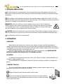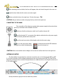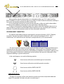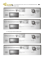
1
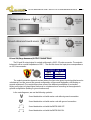
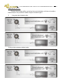
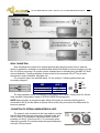
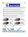
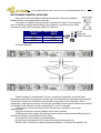
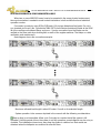
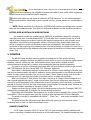
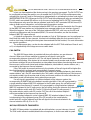
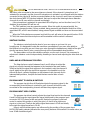
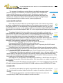
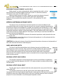
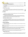
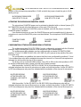
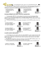
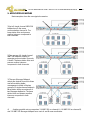
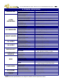
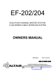
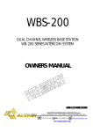
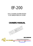
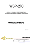
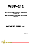
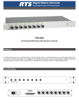
WBS-202
DUAL CHANNEL WIRELESS BASE STATION
WB-200 SERIES INTERCOM SYSTEM
OWNERS MANUAL
Issue May 09
CENTRALE INTERCOM HF
DIGITAL FUNKINTERCOM BASISSTATION
AUDIO ELECTRONICS DESIGN
EQUIPOS EUROPEOS ELECTRÓNICOS, S.A.L
Avda. de la Industria, 50. 28760 TRES CANTOS-MADRID (SPAIN).
34-91-761 65 80
34-91-804 43 58
www.altairaudio.com
[email protected]
WB-200 SERIES INTERCOM SYSTEM — WBS-202 DUAL CHANNEL WIRELESS BASE STATION
2
1. INTRODUCTION..................................................................................................................................................3
2. SWITCHES, CONTROLS, ADJUSTMENTS AND CONNECTORS..............................................................................4
FRONT PANEL ...................................................................................................................................................4
REAR PANEL......................................................................................................................................................5
3. WORKING PRECAUTIONS ..................................................................................................................................6
4. INSTALLATION ..................................................................................................................................................6
UNPACKING.....................................................................................................................................................6
MOUNTING.......................................................................................................................................................6
CHANGING THE FUSE.......................................................................................................................................6
CONNECTING TO THE MAINS ...........................................................................................................................7
ANTENNA MOUNTING......................................................................................................................................7
PROGRAM INPUT CONNECTION.......................................................................................................................8
UNBALANCED INPUT: .........................................................................................................................................................8
BALANCED INPUT:..............................................................................................................................................................10
PA and SA (Stage Announce) OUTPUT CONNECTIONS....................................................................................10
UNBALANCED OUTPUT: ...................................................................................................................................................11
BALANCED INPUT:..............................................................................................................................................................12
RELAY CONNECTION .......................................................................................................................................12
CONNECTION TO EXTERNAL WIRED INTERCOM UNITS ....................................................................................12
MULTICHANNEL OPERATION. AUDIO LINKS ....................................................................................................14
MULTIBASE OPERATION. SYNCHRONISATION LINKS .......................................................................................15
SYSTEMS WITH MORE THAN 20 WIRED BELTPACKS........................................................................................16
5. OPERATION......................................................................................................................................................16
HEADSET CONNECTION...................................................................................................................................16
HEADSET VOLUME CONTROL...........................................................................................................................17
REMOTE MUTE ALL MICS AND BUZZER SWITCHES ..........................................................................................17
STAGE ANNOUNCE (SA) SWITCH.....................................................................................................................17
CALL SWITCH ..................................................................................................................................................18
MIC ON/OFF/PUSH TO TALK SWITCH..............................................................................................................18
SIDETONE CONTROL .......................................................................................................................................19
LINE A AND B LISTEN BALANCE CONTROL........................................................................................................19
PROGRAM INPUT TO LINES A/B SWITCHES ....................................................................................................19
PROGRAM INPUT LEVEL CONTROL...................................................................................................................19
PROGRAM TO HEADPHONES CONTROL..........................................................................................................20
RADIO REGISTER SWITCHES............................................................................................................................20
IN RANGE LEDS...............................................................................................................................................20
MODE SELECTOR SWITCH RADIO 2 to CH-1/CH-2. .........................................................................................21
INTERCOM LINE TERMINAL IMPEDANCE SWITCH.............................................................................................21
LINES A AND B LINK SWITCH...........................................................................................................................21
PROGRAM OUTPUT GAIN CONTROL ...............................................................................................................21
PROGRAM OUTPUT SIGNAL SELECT.................................................................................................................21
PROGRAM INPUT MIC/LINE LEVEL SELECTOR ..................................................................................................22
SA OUTPUT GAIN CONTROL...........................................................................................................................22
6. OPTIONS.........................................................................................................................................................22
OMNIDIRECCIONAL ANTENNA (0A-P0360) ....................................................................................................22
DIRECTIONAL ANTENNA (DA-P6060) ..............................................................................................................22
7. SPECIAL OPERATIONS......................................................................................................................................22
CHANGING THE MIC GAIN..............................................................................................................................22
ACTIVATING THE MICROPHONE PHANTOM POWER.......................................................................................23
CONFIGURATION OF THE MULTIPURPOSE RELAY ACTIVATION .......................................................................23
PROGRAM INTERRUPT WITH THE MIC SWITCHES CONFIGURATION................................................................24
SA SWITCH MODE CONFIGURATION..............................................................................................................24
8. BLOCK DIAGRAM ............................................................................................................................................25
9. APPLICATION EXAMPLES.................................................................................................................................26
10. TECHNICAL SPECIFICATIONS...........................................................................................................................27
11. WARRANTY ....................................................................................................................................................28
WB-200 SERIES INTERCOM SYSTEM — WBS-202 DUAL CHANNEL WIRELESS BASE STATION
3
1. INTRODUCTION
Congratulations on your purchase of the ALTAIR dual channel wireless base station WBS-202 of
the WB-200 series wireless intercom system. There is a lot the characteristics that make of the ALTAIR
WB-200 series one of the most highlighted in the audio professional market, some are enumerated
here:
Dual pre-amble diversity antenna system, detects and selects the higher radio signal ensuring better
coverage and minimum drop-outs.
Digital encryption process allows high security conversations.
Two detachable omni antennas are provided with the unit. External high gain directive antennas
can be mounted when desired to increase the coverage area.
The new Altair WBS-202 wireless base station doubles the capacity of the single channel WBS-200
maintaining full compatibility. The front panel design is inspired in the very known double channel EF200 wired intercom base station.
The unit features a complete double channel radio link with a capacity of up to 4 wireless beltpacks
per channel. By the use of a single switch button, channel B is engaged to channel A allowing a total
capacity of up to 8 wireless beltpacks per base station, in single channel configuration.
The new system includes a new double channel, Manager beltpack WBP-202, with channel
selection, listen balance adjustment of each channel and SA, stage announce function. All this features
allows great versatility to the production Manager allowing full communications capability into two
separate crews.
The system comprises a powered base station WBS-202, and battery powered beltpacks WBP-200
(single channel) and/or WBP-202 (dual channel). Base station is designed to operate in stand alone or
“Master” mode enabling full duplex clear and secure communications. For large system operation, the
unit can be used in “Slave” mode by wiring units across the coverage area, so expanding the number
of wireless users in a cellular arrangement.
Depending of the installation, base stations can also be powered remotely from a wired EF-200
base station. The base incorporates party line outputs to drive standard EM-201 wired beltpacks.
Before beginning it is important to read this manual. This manual will help you to install and use
your new intercom master station. It is very important to read it carefully, mainly the paragraphs
marked as NOTE, PRECAUTION and DANGER, for your security.
Save the original packing, you can re-use it to transport the unit. NEVER SHIP THE ALTAIR WBS202 WITHOUT ITS ORIGINAL PACKING.
4
WB-200 SERIES INTERCOM SYSTEM — WBS-202 DUAL CHANNEL WIRELESS BASE STATION
2. SWITCHES,
CONTROLS, ADJUSTMENTS AND CONNECTORS
These are the
The description and
switches, controls, adjustments and connectors that you can find in your ALTAIR
explanation of each one will be found in the corresponding section.
wireless intercom base station.
FRONT PANEL
ANTENNA 1.
HEADSET CONNECTORS.
ANTENNA 2.
MIC ON/OFF/PUSH
TO TALK SWITCH AND
SIDETONE CONTROL.
PROGRAM INPUT
TO LINES A/B SWITCHES.
LINE A AND B LISTEN
BALANCE CONTROL.
PROGRAM INPUT
LEVEL CONTROL.
HEADSET VOLUME CONTROL.
GLOBAL REMOTE BUZZERS and
ALL- MICS SWITCHES.
STAGE ANNOUNCE (SA)
ENABLE SWITCH.
PROGRAM INPUT TO
HEADPHONES CONTROL.
MODE SELECTOR SWITCH
RADIO 2 to CH-1 /CH-2.
RADIO REGISTER SWITCH
AND IN RANGE LEDS.
POWER SWITCH.
CALL SWITCH.
5
WB-200 SERIES INTERCOM SYSTEM — WBS-202 DUAL CHANNEL WIRELESS BASE STATION
REAR PANEL
IEC MAINS CONNECTOR.
FUSE HOLDER.
G RJ-11 SYNCHRONISATION
OF MULTIPLE UNITS.
STAGE ANNOUNCE OUTPUT AND GAIND ADJ.
PROGRAM INPUT AND MIC / LINE
LEVEL SELECTOR.
PARTY LINE OR MIC ONLY SELECTOR/GAIN ADJ,
AND OUTPUT CONNECTOR
GENERAL PURPOSE
RELAY CONNECTOR.
MINI JACK 3,5MM, AUDIO
LINK BETWEEN UNITS.
GENERAL PURPOSE IN/OUT.
TERMINAL IMPEDANCE MODE SELECTOR. SELECT SLAVE
WHEN UNIT IS LINKED TO ANOTHER TERMINATED INTERCOM LINE.
INTERCOM LINES CONNECTIONS A /B.
LINES A/B LINK.
SMA SECONDARY
ANTENNA CONNECTORS.
WB-200 SERIES INTERCOM SYSTEM — WBS-202 DUAL CHANNEL WIRELESS BASE STATION
6
3. WORKING PRECAUTIONS
The manufacturer is not responsible of any damage that can possibly happen to the intercom
base station outside the limits of the warranty or those produced by not taking care with the working
precautions.
Mains voltage must be between the limits of the admitted power supply (90-264 VAC, 50-60 Hz)
and that the fuse must be the appropriate (2A slow blow type: T2A). Damage caused by connection to
improper AC voltage is not covered by any warranty.
DANGER: Inside the unit there are high voltages, do not open it. The unit does not
contain elements that could be repaired by the user. Whenever the intercom base station
is connected to the mains, it carries elements with high voltages. In order to disconnect
the unit completely, you must disconnect it from the mains.
CAUTION: Protect the unit from the rain and moisture. Ensure that no objects or liquids enter it. If
liquid is spilled into the unit, disconnect it from the mains and consult a qualified service technician.
Do not place the unit close to heat sources.
4. INSTALLATION
UNPACKING
Before leaving the factory, each intercom base station has been carefully inspected and
tested. Unpack and inspect the unit for any damage that may have occurred during shipment. If
any damage is found, does not connect the unit to the mains; notify the sales person immediately;
a qualified service technician should inspect the unit.
Save the original packing, you could use if you need to transport the unit. NEVER SHIP THE
INTERCOM MASTER STATION WITHOUT ITS ORIGINAL PACKING.
MOUNTING
It is always recommended to mount the unit in rack, either for mobile or fixed installations, for
protection, safety, aesthetics, etc.
The ALTAIR WBS-202 is designed for standard 19" rack mounting, and takes up 1u high rack
space.
CHANGING THE FUSE
This unit incorporates an internal, worldwide voltage operation power supply, and it is
prepared to work from 90 to 264 VAC, 50-60Hz.
Make sure that the unit is disconnected from the mains.
In the unit rear panel are placed the mains connector, the mains selector
and the fuse holder. The box bellows this mains connector is called fuse holder.
Take out the fuse holder.
WB-200 SERIES INTERCOM SYSTEM — WBS-202 DUAL CHANNEL WIRELESS BASE STATION
7
After extracting the fuse holder, the fuse will appear, take out it and change for the new one.
Insert the fuse holder into the mains connector again.
Make sure that the fuse is the right one: 2A slow blow type - T2A
CAUTION: Always make sure after changing the fuse, that it is the right one.
CONNECTING TO THE MAINS
The connection of the intercom master station power supply to the mains takes
place by a standard cord included in the box.
Make sure that the unit power switch is at 0 position (turned off).
Insert the female I.E.C. connector of the tripolar cable into the unit power supply
male connector, placed at the rear panel.
Insert the male connector of the tripolar cable into the mains plug.
Turn on the unit power switch.
will light for a while, indicating that
In that moment all the LED indicators
the unit is turned on.
CAUTION: Make sure that the mains voltage is the correct as well as their fuse is the right one.
ANTENNA MOUNTING
The base station incorporates four antenna connectors, two on the front panel (ANT 1 y ANT
2),), for the connection of the included antennas and two on the rear panel (ANT-1R y ANT-2R) for
secondary antennas when needed. Best performance is obtained when mounting the antennas in
a 90º angle position.
Same procedures apply for the rear antennas position.
WB-200 SERIES INTERCOM SYSTEM — WBS-202 DUAL CHANNEL WIRELESS BASE STATION
8
When possible, place the base station in an elevated position, say 1.5-2 meter from floor.
When installed on a rack, choose the upper one position in order to have the antennas radiating in
free space and avoiding interferences with another unit.
It is not absolutely necessary to mount the rear antennas as they are used for base station
diversity and the beltpack incorporates its own dual antenna diversity system.
In order to increment the operating range of the system, place the supplied antennas in an
upper position by using the recommended support accessory, or by using high gain accessory
antennas. Consult the accessories section for more information about this.
PROGRAM INPUT CONNECTION
The intercom base station program input signal is carried out through a XLR-3-31 female
connector. The input connection is balanced, with a nominal impedance of 40 KΩ (20 KΩ
unbalanced). The next list shows the input pins correspondence as A.E.S recommends:
PROGRAM INPUT - XLR-3-31
0V
PIN 1
PIN 2
HOT (+)
COLD (-)
PIN 3
The input connection depends on two factors, the first is the type of input signal balanced or
unbalanced, and the second the ground configuration of the sound source (floating or groundreferenced). The next pictures show some of the different possibilities of connection, relying on the
type of input signal, balanced or unbalanced and according to the ground configuration of the
equipment (floating or ground-referenced).
In the next diagrams, we use the following symbols:
Sound source with mains cord without ground connection.
Sound source with mains cord with ground connection.
Sound source with the EARTH-LINK OFF.
Sound source with the EARTH LINK ON.
UNBALANCED INPUT:
This type of connection will be used when the sound source does not provide balanced
output. If it’s possible it is better using the connection type 1.
WB-200 SERIES INTERCOM SYSTEM — WBS-202 DUAL CHANNEL WIRELESS BASE STATION
1) Using twin-lead shielded cable:
2) Using single conductor shielded cable:
9
WB-200 SERIES INTERCOM SYSTEM — WBS-202 DUAL CHANNEL WIRELESS BASE STATION
10
BALANCED INPUT:
PA and SA (Stage Announce) OUTPUT CONNECTIONS
The PA and SA output signal is carried out through a XLR-3-32 male connector. The output is
balanced, with a nominal impedance of 100 Ω. The next list shows the input pins correspondence
as A.E.S recommends:
PA OUTPUT - XLR-3-32
0V
PIN 1
PIN 2
HOT (+)
COLD (-)
PIN 3
The output connection depends on two factors, the first is the type of input signal balanced or
unbalanced, and the second the ground configuration of the sound destination unit (floating or
ground-referenced). The next pictures show some of the different possibilities of connection,
relying on the type of output signal, balanced or unbalanced and according to the equipment’s
ground configuration (floating or ground-referenced).
In the next diagrams, we use the following symbols:
Sound destination unit with mains cord without ground connection.
Sound destination unit with mains cord with ground connection.
Sound destination unit with the EARTH-LINK OFF.
Sound destination unit with the EARTH LINK ON.
WB-200 SERIES INTERCOM SYSTEM — WBS-202 DUAL CHANNEL WIRELESS BASE STATION
UNBALANCED OUTPUT:
This type of connection will be used when the sound destination unit does not provide a
balanced input. If it’s possible it is better using the connection type 1.
1)
Using twin-lead shielded cable:
2) Using single conductor shielded cable:
11
WB-200 SERIES INTERCOM SYSTEM — WBS-202 DUAL CHANNEL WIRELESS BASE STATION
12
BALANCED INPUT:
RELAY CONNECTION
Base unit allows the control of an internal general relay allowing control over an external
device or application. Activation is controlled either with the SA (Stage Announce) function or by the
Mic A or B front panel keys. SA function can be activated local or remotely from the WBP-202 dual
channel beltpacks. Typical application of relay control is the command of the PTT key in radio
transceivers, motor controllers, tally lights, etc.
The connector type is an standard stereo 3.5 mm minijack. Following table shows the
connection diagram.
TIP
RELÉ
JACK ¼”
RING
COMMON
RING
SLEEVE
NORMALLY CLOSED
TIP
NORMALLY OPEN
SLEEVE
The relay operation mode is configured by an internal micro switch. Factory set to SA. See the
other possible configurations bellow in SPECIAL OPERATION paragraphs.
NOTE: Relay operation is changeover type: When the function is not active, the Ring pole is
connected to the Tip ant the Sleeve is opened. When active, Ring connects to the Sleeve and Tip
becomes opened.
CONNECTION TO EXTERNAL WIRED INTERCOM UNITS
The external units connection to the base station is carried
through twin-lead standard microphone shielded cable and
XLR-3-31/XLR-3-32 connectors. Each base station channel
provides one XLR-3-31 and one XLR-3-32 connectors wired
internally in parallel. The next list shows the signal distribution
in the pin XLR connectors.
WB-200 SERIES INTERCOM SYSTEM — WBS-202 DUAL CHANNEL WIRELESS BASE STATION
13
XLR-3-31/XLR-3-32 — INTERCOM LINE
GND
PIN 1
PIN 2
+VDC
SIGNAL
PIN 3
Certain rules have to be followed when installing the cables of an intercom system. This is to
avoid ground loops and to minimize the power loss and possible effect of electromagnetic fields.
Do not connect the XLR pin 1 to the XLR metal housing or to metal wall boxes to avoid ground
loops. The ground loop could increase notably the system background noise.
Do not close the intercom line connection (avoid closed loops). Each intercom line leaves from
the base station towards the remote stations, but it does not return to the master station. If the
connection is closed, a ground loop with the increase from the system noise will take place.
Use high quality cables and minimize its longitude. Avoid using low quality cables and
excessive cable runs as it affects in power loss, channel crosstalk and frequency response.
Place the base station in the closest possible position to the maximum consumption zone; that
is to say to the zone in which more external units are placed.
The next picture shows the habitual connection of an intercom system comprised by four
beltpack units (two per channel) and a WBS-202 base station.
WB-200 SERIES INTERCOM SYSTEM — WBS-202 DUAL CHANNEL WIRELESS BASE STATION
14
MULTICHANNEL OPERATION. AUDIO LINKS
Rear panel audio links allows multichannel operation sharing the headset
between bases, so accessing all the channels.
Connection is made by using two leads composed of 2 stereo 3,5 mm jacks at
each end wired in inverted mode and by using miniature 2 conductors plus shield
microphone cable. See the diagram bellow for reference.
JACK 3,5 mm — MULTICHANNEL
UNIT A
UNIT B
TIP
RING
RING
TIP
SHIELD
SHIELD
TIP (in)
RING (out)
SHIELD (common)
Schematic diagram:
System operation is strait forward. You can connect your headset to any of the bases.
Microphone signal from the preamp out of the base #2 is directed to the preamp input in base#1.
Channel Mic A and B on/off switches from base#2 corresponds now to channels C and D
respectively. Listening from the four channels are controlled by local volume and balance controls
as depicted in this manual, A and B on base#1 and C and D on base#2.
Call signaling, remote mic kill and buzzer kill are to be controlled on each base
independently.
Program input signal must be splitted to each base if needed.
SA (Stage announce) outputs from the two bases must be combined externally by using an
audio mixer and then connected to the PA system.
This audio links allows advanced functionalities:
Mic link-Direct microphone out, Mic input from external equipment, etc
EAR link-Listen connection to external powered speakers, cue input to the operator, etc
WB-200 SERIES INTERCOM SYSTEM — WBS-202 DUAL CHANNEL WIRELESS BASE STATION
15
MULTIBASE OPERATION. SYNCHRONISATION LINKS
When two or more WBS-202 bases have to be operated in the same physical environment,
time synchronization is needed to avoid mutual interactions in both multichannel and individual
operation modes.
Connection is made by using RJ11 to RJ11 leads, 6/4 pin type (telephone line leads). Pin out is
non inverted: pin1 to pin1, etc. Connect the SYNK OUT from the base considered Master to the SYNK
IN of the next base considered Slave, and so on. Synchro connection from the Master can be
verified on the Slave units by a double glitch on each of the register switches. That helps on cable
verification and maintenance.
Next diagram shows the connection example:
Maximum allowed lead length is about 50 meter. Consult us for extended length.
System operation is the same as depicted in the manual with the following considerations:
Start-up time is not immediate. Allow up to 5 minutes to consider that all the system is full
operative. Until this period of time, the system is not fully operative; some beltpacks can be noisy or
unstable. This initialization time occurs every time the system is switched on. Best results are
obtained when the beltpacks are switched on after this time.
WB-200 SERIES INTERCOM SYSTEM — WBS-202 DUAL CHANNEL WIRELESS BASE STATION
16
When first time registering it is advisable to register first radio R1, then switch off the registered
beltpacks and now proceed with the R2 beltpacks.
Powering the bases are the same as habitual in ALTAIR intercoms. You can choose between
powering each station individually or from a remote line from another station or a combination of
both.
NOTE: Please remember to configure the MASTER/SLAVE switches accordingly when connect
intercom lines between bases. One must be configured as Master and the remaining as Slaves.
SYSTEMS WITH MORE THAN 20 WIRED BELTPACKS
It is possible connect two master stations (WBS-202) in installations where it is necessary
work with more than 20 wired beltpacks (EM-201), with their lines in parallel (A with A and/or B
with B), always having the caution of opening the terminal impedance (in order to obtain more
information, consult the special operation section), of the secondary master station lines that
serves us simply how power reinforcement. In this type of operations, the master station unit is
connected at the beginning of the intercom chain, and the secondary unit at the end of this line, in
this way, we will reinforce the beltpack units power placed to the other end of the primary master
station unit.
5. OPERATION
The WB-200 series wireless intercom systems are designed to allow maximum easy
communication operations between the different control areas in music or theatre live performances,
television, cinema, conference halls, and whatever broad events where multiple and fast
communications are required, by means of its simultaneous listening-speaking operation.
The system comprises a powered base station WBS-202 and battery powered single channel
WBP-200 beltpacks and dual channel WBP-202 “Manager” beltpacks.
Base station is designed to operate in stand alone or “Master” mode enabling full duplex clear
and secure communication with up to 8 beltpacks and the base operator in simultaneous party line
mode. For large system operation, the unit can be used in “Slave” mode by wiring units across the
coverage area, so expanding the number of wireless users in a cellular arrangement.
Base unit comprises 2 radio blocks. Each block can link up to 4 single channel beltpacks or 1
dual channel beltpack plus up to 3 single channel ones. Each block is assigned to each intercom
channel A and B respectively having independent channel operation. In the case that it is desired to
operate in the same channel, the base incorporates a single switch “R2 channel select” allowing all
the 8 wireless beltpacs operating in the same channel, ChA.
Stage announces can be carried out from the base operator or from the “Manager” WBP-202
beltpacks by connecting the SA output to the corresponding equipment.
Depending of the installation, base stations can also be powered remotely from a wired EF-200
base station. The base incorporates party line outputs to drive standard EM-201 wired beltpacks.
The wired connection is compatible with Espiral™, Clear-Com™ and similar compatible 2 and
4 wire systems.
The global all mic (Mic-Kill) and buzzers (Buzz-Kill) mute systems in both channels, allow
controlling the line noise, as well as the ambient noise.
HEADSET CONNECTION
A XLR-4 type connector (XLR-4-32) and a TINY Q-G type connector wired in parallel mode,
allows connecting a headset with microphone to the master station. The headset impedance must
WB-200 SERIES INTERCOM SYSTEM — WBS-202 DUAL CHANNEL WIRELESS BASE STATION
17
be 200 Ω or higher (up to 2 KΩ) and the microphone must be dynamic or electret type.
The microphone preamplifier gain can be configured with an internal preset in +30 or +40
dB. (In the factory set-up the microphone preamplifier gain is adjusted to +30 dB)
For the electret microphone type it is necessary to enable the phantom power of 9 VDC with
an internal preset. In order to obtain more information, consult the special operation section.
The next list shows the XLR pins correspondence:
HEADSET - XLR-4-32 — TINY Q-G
0 V (MICROPHONE)
PIN 1
SIGNAL (MICROPHONE)
PIN 2
0 V (HEADPHONES)
PIN 3
SIGNAL (HEADPHONES)
PIN 4
NOTE: Headphones can be with a double or single muff. In case of using a double muff
headphone, the two speakers should be wired in parallel mode.
HEADSET VOLUME CONTROL
The volume control allows attenuating or amplifying the signal sent to the
headphones. This control adjusts the listen level to the headphones as you wish.
REMOTE MUTE ALL MICS AND BUZZER SWITCHES
These switches allow to disable all the microphones (ALL MICS) and all
the buzzers (BUZZERS) of both channels of the intercom system (including all
the wired and wireless beltpacks, desk station units and master station slave
units) except the one from the base station from that these switched are
activated (the buzzer remote mute affect to the base station).
The remote mute ALL MICS switch carries out the function upon pressing it. This means that
the units (wired and wireless beltpacks, desk stations units, etc.) connected to the system can turn
on the microphones again when it’s required. When this switch is pressed, its associated LED turns
on during a moment.
The BUZZERS switch, on the other hand, carries out an on/off function. If the remote mute
buzzers function was enabled, when the remote mute buzzers switch is pressed the remote mute
buzzers function is disabled and the associated LED becomes turned off (in this moment all the
external units could enable their local buzzers again); if, on the other hand, it was disabled, when
the remote mute buzzers switch is pressed the remote mute buzzers function is enabled and the
associated LED becomes turned on (at this moment the buzzers of all the external units will be
disabled and they can not be enabled again locally).
The BUZZER ON/OFF of the base station is carried out with the BUZZER REMOTE MUTE,
enabling/disabling the buzzer sound when the unit receives a call or when the user presses a key.
STAGE ANNOUNCE (SA) SWITCH
The SA switch allows to enable the SA (stage announce) OUTPUT placed at the rear
panel, which normally is disabled, and to carry out this way the microphone signal
sending picked up in the HEADSET to another audio systems, activating at the same time the
multipurpose relay (PA OUTPUT RELAY) placed at the rear panel (factory set-up). This switch has an
associated LED that indicates the state of the SA output (the LED is on when the microphone is
routed to the PA output).
WB-200 SERIES INTERCOM SYSTEM — WBS-202 DUAL CHANNEL WIRELESS BASE STATION
18
In fact, we have explained the factory set-up in the previous paragraph. The PA OUTPUT can
be configured to always be enable, one can enable the PA OUTPUT and the multipurpose relay
activating the channel A and/or B microphone independently or activating the buzzer mute signal
(BUZZER REMOTE MUTES). Whenever the PA OUTPUT and the multipurpose relay are activated, the
PA-MIC switch associated LED will turn on (in the case of activating the PA OUTPUT permanently,
the multipurpose relay won't be always activated, and the PA-MIC associated LED will turn off). In
order to obtain more information, consult the special operations section.
The microphones of the manager beltpacks WBP-202 can also be directed to the PA output
(in the WBS-202 base station can be registered one manager beltpack per wireless channel).
When this happens, from any of the 2 wireless beltpacks WBP-202, also turns on the LED and
active the multipurpose relay associated (RELAY). For more information, see the the wireless
beltpack WBP-202 owner manual.
In it default configuration, this switch operates as Push to Talk however, can be configured so
that if hold this switch for four seconds, it turned out indefinitely (after this four seconds, the unit
emits a short beep, indicating that the system have entered into this function). For more information
see special operations.
The multipurpose relay, can be also be activated with the MIC TALK switches of lines A and /
or B, or independently of the stage announce switch state.
CALL SWITCH
The WBS-200 base station is provided with two call switches, one per intercom
channel. When one of these switches is pressed a call signal is sent to the
corresponding intercom channel (A or B). The call signal makes the LED associated with
the switch start blinking; if the buzzer its not remote muted (consult remote mute all mics
and buzzer switches for more information) an intermittent sound takes place during three seconds,
the same as in all the units (wired and wireless beltpacks, desk stations, master stations, etc.),
connected to the intercom channel selected.
If the CALL switch is pressed continuously, the duration of the call signal will be higher (the
time that the switch is pressed, and approximately 3 seconds more).
If a call signal is generated in an external unit (wired and wireless beltpacks, desk stations,
master stations, etc.), the LED associated to the CALL switch, will start blinking and if the buzzer is
not remote muted (consult remote mute all mics and buzzer switches for more information) an
intermittent sound will take place during about three seconds.
If a call signal is generated in a wireless beltpack of the intercom system, the
corresponding IN RANGE led to the beltpack number start blink. If this call is generated by
a single wireless beltpack WBP-200 registered in the R1 radio group, the call will be sent
to the intercom line channel A, however, if it is generated by a single wireless beltpack
WBP-200 registered in the R2 radio group, the call will be sent to the intercom line channel A , if
the mode selector switch radio R2 is set to CH1 (join the R1 and R2 radio groups), if
this mode selector switch radio R2 is set to CH2, the call of the wireless beltpack
will be transmitted to the intercom line channel B.
If the wireless beltpack is a dual channel WBP-202 wireless beltpack, the call
is independent of the registered group (R1 or R2) as well as the mode selector
switch radio R2 and the beltpack send the call signal to the channel selected in its
channel selection LEDs (A, B or A + B).
MIC ON/OFF/PUSH TO TALK SWITCH
The WBS-202 base station is provided with two talk switches, one per intercom channel.
The TALK switch allows to enable/disable the microphone, so that we are able to speak
WB-200 SERIES INTERCOM SYSTEM — WBS-202 DUAL CHANNEL WIRELESS BASE STATION
19
with other units connected to the same intercom channel. If the channel A microphone isn’t
activated (for example), and the channel B microphone is activated, we will speak with the stations
connected to the channel B, but the connected stations to the channel A won’t hear us (except for
the dual channel WBP-202 wireless beltpack, that can be adjust the listening balance between
channels A and B, even with the channel unselected).
If the microphone is activated, its associated LED will light up, and on the other hand, if it is
disabled, its associated LED will turn off.
The TALK switches have two operation modes. When this switch is pressed quickly, the
microphone changes its state; if it was enabled, being pressed it gets disabled and turns off the
associated LED, and if it was disabled, being pressed it gets enabled and turns on the associated
LED.
When the TALK switches are pressed and held, the unit will enter in the special function PUSH
TO TALK; this means that the microphone will be enabled until the switch is released.
SIDETONE CONTROL
The sidetone control adjusts the level of your own voice as you hear it in your
headphones. It is designed to make the maximum cancellation of your own voice totally to
the left (that is to say that you won't hear your voice through the headphones), totally to the right
give the maximum level of voice, passing through all the intermediates level positions.
The base station unit has two sidetone controls, one for each channel. It is necessary to
adjust each sidetone control independently, disabling a channel and adjusting the other and vice
versa.
LINE A AND B LISTEN BALANCE CONTROL
The listen balance control between lines A and B allows to adjust the
signal mix of both channels that appears in the headset of the main station.
Totally to the left, the signal that appears in the headset is only the channel A
signal, totally to the right, the signal that appears in the headset is only the
channel B signal, centered it appears a mix between both channels and in
intermediates positions, it adjusts the level that we want to listen of each
channel.
PROGRAM INPUT TO LINES A/B SWITCHES
The program input to lines A/B switches injects the program signal in the
corresponding channel (there is a switch for each channel) and all the units
connected to the corresponding channel will listen the program signal.
PROGRAM INPUT LEVEL CONTROL
The program input level control adjusts the signal level sent to the channels
A and B of the program input signal (the signal introduced by the program input
connector XLR-3-31 placed at the rear panel). Next to the program input level
control is marked the position in which the gain is 0, that is to say the same
signal as in the input. Totally to the left the signal decreases in 10 dB and totally
to the right the signal increases in 20 dB.
Keep in mind that these gains are influenced by the position of the program input
MICRO/LINE switch selector (placed at the rear panel), because if this switch is in mode micro, we
have 30 dB of additional gain.
WB-200 SERIES INTERCOM SYSTEM — WBS-202 DUAL CHANNEL WIRELESS BASE STATION
20
PROGRAM TO HEADPHONES CONTROL
The program to headphones control allows to regulate the program signal
level that appears in the headsets connected to the base station unit WBS-202,
independently if the program sending to lines A/B switches is pressed or not.
Keep in mind that if the program input signal is sent to the lines, the signal sent
directly to the headphones directly will be added to the signal sending directly to
the lines (attenuated by the sidetone control, previously explained).
RADIO REGISTER SWITCHES
Each radio group (R1 and R2) have a radio register switch. This switches are provided
to register and deregister the wireless beltpacks of the wireless intercom system. On each
base station WBS-202 can be registered up to eight wireless beltpacks (four per group, R1
and R2). Within each group we can register a dual channel wireless beltpack WBP-202 and
three single channel wireless beltpacks WBP-200 or four single channel wireless beltpacks WBP200.
To register a beltpack to the base station, turn on the base station, and press and
hold the REGISTER switch during six seconds. At this moment the base station will sound (if
the buzzer it is turned on) and will blink the associated REGISTER led and the IN-RANGE (14) leds corresponding where is going away to register the new beltpack. If the base
station has registered four beltpacks already in the group, the function will be reset, and
new beltpacks will not be able to be registered until the deregistration of some beltpack is made or
deregister all the beltpacks registered in the base station group.
If we do not do anything during 60 seconds the function will be reset.
If we pressed key REGISTER again the function will be reset.
With the beltpack that we want to register turned off, turn on pressing the ON/OFF switch
maintaining pressed the VOLUME UP/DOWN switches.
If everything goes well, the base station base will sound (if the buzzer it is turned on) and the
beltpack also (if the buzzer it is turned on), the corresponding base station IN RANGE led will turn on
and the beltpack IN RANGE led begin to blink.
If the procedure fails, turn off the base station and the beltpack and to return to begin.
To deregister all the beltpacks registered in the base station, turn on the base station with the
register switch of the radio group that you can erase the register, pressed until the base station
sounds with all the beltpacks registered to the base station turned off. At this moment, turn off the
base station and all the beltpacks will be deregistered.
Each beltpack can be registered in two different base stations, so that if it loses the range of
one, changes the operation to the other base station. Each base station can register a maximum of
four beltpacks.
If we want to register the beltpack in the base station 2, turn on the beltpack pressing the ON/
OFF switch maintaing pressed the VOLUME UP/DOWN switches and the BUZZER ON/OFF switch.
IN RANGE LEDS
The intercom base station has eight in range leds (four for each radio group R1 and
R2), that indicated the wireless beltpacks that are in range in the wireless system at this
moment.
If a call signal is generated in a wireless beltpack of the intercom system, the
corresponding IN RANGE led to the beltpack number start blink.
WB-200 SERIES INTERCOM SYSTEM — WBS-202 DUAL CHANNEL WIRELESS BASE STATION
21
MODE SELECTOR SWITCH RADIO 2 to CH-1/CH-2.
Radio group 2 can work independently, without pressing this switch, so that
the signal from the wireless beltpacks belongs to radio 2 is sent to the intercom
channel B. In this mode, CH B LED remain on.
With this switch pressed, the radio 2 signals are sent to the intercom channel
A, so the system will operate as a single radio system with eight wireless
beltpacks, all connected to the intercom channel A. In this mode the CH A LED
remain on.
INTERCOM LINE TERMINAL IMPEDANCE SWITCH
The intercom lines should have a terminal impedance to make the different units
connected to them work correctly, however only one can connect a terminal impedance for
line because if they are connected two in parallel, the impedance would diminish in a half;
for this and in order to connect other units with a terminal impedance, it is possible to open
the terminal impedance placed at the base station. If the base station will be work in slave
mode with an intercom master station EF-200, keep in mind that you must leave the WBS-202
intercom line terminal impedance.
Each intercom line has its own intercom line terminal impedance switch placed at the rear
panel of the unit.
With the switch pressed the intercom line terminal impedance is in off mode and with the
switch depressed it is in on mode.
CAUTION: Never leave the intercom line without terminal impedance, because a bad operation of
the units connected to the line would take place.
LINES A AND B LINK SWITCH
The lines A and B link switch allows to join the two channels, so that the same
signal appears in both channels. If the channels A and B are linked, the units connected
to the channel A can communicate with the one connected to the channel B and vice
versa, and the calls carried out in any channel will arrive to all the units connected to
both channels. The wireless beltpacks remain connected to their corresponding line though this
switch remain pressed .
PROGRAM OUTPUT GAIN CONTROL
The program output gain control placed at the unit rear panel allows to regulate the
program signal level that appears in the XLR-3-32 male pa output connector placed at the
unit rear panel.
PROGRAM OUTPUT SIGNAL SELECT
The PA output signal is selected with this switch placed at the rear panel of the base
station WBS-202.
The program output can be the MIC signal of the base station (with this switch
depressed) or the line signal selected with the radio audio signal to A/B intercom line switch. It is
possible to choose an unique intercom line or the sum of the two intercom lines via internal
jumpers. For more information consult the special operation section.
WB-200 SERIES INTERCOM SYSTEM — WBS-202 DUAL CHANNEL WIRELESS BASE STATION
22
PROGRAM INPUT MIC/LINE LEVEL SELECTOR
The program input has a MIC/LINE level selector switch placed at the WBS-202 base
station rear panel.
With the switch pressed (MIC), the base station have an additional gain of 30 dB at the
program input.
SA OUTPUT GAIN CONTROL
The sa (stage announce) output gain control placed at the unit rear panel allows to
regulate the sa signal level that appears in the XLR-3-32 male sa output connector placed
at the unit rear panel.
6. OPTIONS
In this section we will explain the different available options for the base station WBS-202 unit.
OMNIDIRECCIONAL ANTENNA (0A-P0360)
To implement the diversity system in the base station, it is necessary connect two more
omnidirectional antennas in the rear antenna connectors (ANT-1R and ANT-2R). These optional
omnidirectional antennas are the same that the base station front panel.
DIRECTIONAL ANTENNA (DA-P6060)
This accessory is provided with an extension 2 meter low loses coaxial cable. The antenna
must be installed on the wall pointing out the desired area and covers a focused beam of 60
degrees H by 60 degrees V. The panel antenna must be installed on the unit to cover the local
area around the unit.
7. SPECIAL OPERATIONS
In order to set-up some of the base station possibilities, the unit must be opened removing the
six screws of the unit top cover.
NOTE: This type of operations takes place with the unit is opened; the best thing should be to carry it
out by a qualified technician.
DANGER: Before opening the unit, disconnect it from the mains. It is important to indicate that
although the unit is switched off (with the power switch in 0 position), if it keeps being connected to
the mains there are different parts of the unit that are subjected to high voltage.
CAUTION: Protect the base station from the rain and moisture, mostly if it is open. If liquid is spilled
into the unit, disconnect it from the mains and consult a qualified service technician.
CHANGING THE MIC GAIN
The microphone preamplifier gain can be configured with an internal jumper (JP1, MIC GAIN,
placed at the front left corner of the main PCB of the unit) in 30 or 40 dB. With the jumper opened
WB-200 SERIES INTERCOM SYSTEM — WBS-202 DUAL CHANNEL WIRELESS BASE STATION
23
the gain of the microphone preamplifier is 30 dB, and with the jumper closed the gain is 40 dB
(factory set-up).
MICROPHONE PREAMPLIFIER
GAIN SET UP TO 30 dB.
MICROPHONE PREAMPLIFIER
GAIN SET UP TO 40 dB.
ACTIVATING THE MICROPHONE PHANTOM POWER
The microphone PHANTOM power can be activated or disabled with an internal jumper (JP2,
MIC PHANTOM, placed at the front left corner of the main PCB of the unit).
With the jumper open the PHANTOM power is disabled, and with the jumper closed the
PHANTOM power is enabled.
If an electret microphone is used, the PHANTOM power must be enabled and if a dynamic
microphone is used, the PHANTOM power must be disabled. The microphone PHANTOM power is
9 VDC.
PHANTOM POWER
DISABLED.
PHANTOM POWER
ENABLED.
CONFIGURATION OF THE MULTIPURPOSE RELAY ACTIVATION
The multipurpose relay (PA OUTPUT RELAY) can be configured to activate it with the SA switch
pression, and/or activating the channel A or B microphone (TALK) independently.
The multipurpose relay activation can be configured with an internal DIP-SWITCH (DSW1,
positions 1,2 and 3, PA RELAY BY MIC ON A, MIC ON B, SA_KEY), placed at the middle of the main
PCB of the unit).
The configurations are additive, this means that if we have configured the positions 1, 2 and
3, the multipurpose relay will be activated whenever the channel A or channel B microphone are
activated, as well as when the key of SA is pressed.
The factory set-up is with the DSW2 position 3 (SA_KEY) in ON and the other positions in OFF,
so that the multipurpose relay is active only with the SA switch pressed.
With the position 1 of the DIP-SWITCH in ON (MIC ON A), the multipurpose relay will be
activated whenever the channel A microphone is active, and with the position 1 of the DIP-SWITCH
in OFF the multipurpose relay won't be activated with the activation of the channel A microphone.
MULTIPURPOSE RELAY
ACTIVATION WITH THE
CHANNEL A MIC SWITCH
DISABLED.
MULTIPURPOSE RELAY
ACTIVATION WITH THE
CHANNEL A MIC SWITCH
ENABLED.
With the position 2 of the DIP-SWITCH in ON (MIC ON B), the multipurpose relay will be
activated whenever the channel B microphone is active, and with the position 2 of the DIP-SWITCH
in OFF the multipurpose relay won't be activated with the activation of the channel B microphone.
MULTIPURPOSE RELAY
ACTIVATION WITH THE
CHANNEL B MIC SWITCH
DISABLED
MULTIPURPOSE RELAY
ACTIVATION WITH THE
CHANNEL B MIC SWITCH
ENABLED.
WB-200 SERIES INTERCOM SYSTEM — WBS-202 DUAL CHANNEL WIRELESS BASE STATION
24
With the position 3 of the DIP-SWITCH in ON (SA KEY), the multipurpose relay will be activated
whenever the SA switch will be pressed, and with the position 3 of the DIP-SWITCH in OFF the
multipurpose relay won't be activated when the SA switch will be pressed.
MULTIPURPOSE RELAY
ACTIVATION WITH THE
SA SWITCH
DISABLED.
MULTIPURPOSE RELAY
ACTIVATION WITH THE
SA SWITCH
ENABLED.
PROGRAM INTERRUPT WITH THE MIC SWITCHES CONFIGURATION
The base station WBS-202 can be configured to make the program input signal will be
interrupted while the channel A and/or B MIC is activated with an internal DIP-SWITCH (DSW1,
positions 4 and 5, PROGRAM INTERRUPT LINE A, PROGRAM INTERRUPT LINE B, placed at the middle
of the main PCB of the unit).
The factory set-up disables both program interruptions. The DIP SWITCH positions 5 and 6 in
OFF.
PROGRAM INTERRUPT
WITH THE CHANNEL A WITH
MIC SWITCH DISABLED.
PROGRAM INTERRUPT
THE CHANNEL A
SWITCH DISABLED.
PROGRAM INTERRUPT
WITH THE CHANNEL B WITH
MIC SWITCH DISABLED.
PROGRAM INTERRUPT
THE CHANNEL B
MIC SWITCH DISABLED.
SA SWITCH MODE CONFIGURATION
The SA (Stage Announce) switch of the base station WBS-202, can be configured so that after
hold it 5 seconds pressed, remain pressed on permanent (latch) or that the switch work always in
the PTT (Push to Talk) mode. In the latch mode, when it is pressed continuously, the base station
emits a slight beep.
The SA switch configuration mode was made by an internal DIP-SWITCH (DSW1, position 6, SA
LATCH MODE, placed at the front left of the base station main board).
The factory default mode disables LATCH work, that is the position of this 6-DIP SWITCH OFF.
SA SWITCH CONFIGURED
IN PTT (Push to Talk) MODE.
SA SWITCH CONFIGURED
IN LATCH MODE.
WB-200 SERIES INTERCOM SYSTEM — WBS-202 DUAL CHANNEL WIRELESS BASE STATION
8. BLOCK DIAGRAM
25
WB-200 SERIES INTERCOM SYSTEM — WBS-202 DUAL CHANNEL WIRELESS BASE STATION
9. APPLICATION EXAMPLES
Next examples show the more typical scenarios.
1) Up to 8 single channel WPB-200
beltpack are in the same
communication channel A. The
base station links and powers
another intercom component in
both channels.
2) Two groups of 4 single channel
WBP-200 beltpack working in
separate communication channels
A and B. The base station links and
powers another intercom
component in both channels.
3) The new Manager Beltpack
selects the desired channel to listen
and talk enabling better
management control of the two
groups of 3 single channel beltpack.
Base station drives a maximum of
two Manager beltpacks. The base
station links and powers another
intercom component in both
channels.
4)
Another possible set-up comprises 3 X WBP-200 on channel A, 4 X WBP-200 on channel B,
and 1 X WBP-202 Manager beltpack as a main A and B crew coordinator.
26
WB-200 SERIES INTERCOM SYSTEM — WBS-202 DUAL CHANNEL WIRELESS BASE STATION
10. TECHNICAL SPECIFICATIONS
INTERCOM LINE
SYSTEM
SPECIFICATION
MIC PREAMPLIFIER
HEADSET AMPLIFIER
P.A. OUTPUT
S.A. OUTPUT
PROGRAM INPUT
IMPEDANCE:
NOMINAL/MAXIMUM LEVEL:
FREQUENCY RESPONSE:
VOLTAGE OPERATION:
DYNAMIC RANGE:
BRINGING IMPEDANCE @ 1KHz:
SIDE-TONE CANCELLATION:
MAXIMUM CABLE LENGTH:
RECOMMENDED WIRE TYPE:
CALL SIGNAL:
CALL THRESHOLD:
REMOTE MIC-OFF:
REMOTE BUZZER-OFF:
MICROPHONE TYPE:
INPUT IMPEDANCE:
NOMINAL/MAXIMUM LEVEL:
PRESENCE FILTER:
PHANTOM VOLTAGE:
IMPEDANCE:
MAXIMUM LEVEL:
OUTPUT POWER:
FREQUENCY RESPONSE:
RESIDUAL NOISE:
TYPE/ IMPEDANCE:
OUTPUT ADJUSTMENT
NOMINAL/MAXIMUM LEVEL:
TYPE/IMPEDANCE
OUTPUT ADJUSTMENT
NOMINAL/MAXIMUM LEVEL:
TYPE:
IMPEDANCE (LINE/MIC):
INPUT LEVEL:
MULTICHANNEL
OPERATION
RADIO
AUDIO LINKS
SYNCHRO LINKS
FREQUENCY:
MODULATION:
TRANSMIT POWER:
RECEIVE SENSITIVITY:
NUMBER OF BELTPACKS PER BASE:
RANGE:
POWER SUPPLY
ACCESSORIES
DIMENSIONS
WEIGHT
MAINS VOLTAGE:
POWER SUPPLY:
PROTECTIONS:
POWER REQUIREMENTS:
DIRECTIONAL ANTENNA:
OMNIDIRECTIONAL ANTENNA
•
•
•
•
•
•
•
•
•
•
•
•
•
•
•
•
•
•
•
•
•
•
•
•
•
•
•
•
•
•
•
•
•
•
•
220 Ω AC/4700 Ω DC.
-10 dBu / +3 dBu.
100 Hz — 10 KHz (-3 dB).
+12 a +30 VDC.
80 dB.
> 20 KΩ.
Adjustable from 0 to 30 dB @ 1 Khz.
500-2.000 meter. Depends on installation.
Shielded mic cable 2 x 0.30 mm2.
+2,8 mA/11 VDC.
3 VDC.
Power interruption: 100 ms.
10 Hz / 800 mVp.
Dynamic or electret.
4K7.
-45 dBu (H)/-20 dBu(L).(internal preset).
+6 dB @ 4700 Hz.
+9 VDC (internal preset ).
200 Ω (nominal), 2KΩ (maximum).
20 Vpp (200 Ω).
250 mW (200 Ω).
250 Hz - 15 KHz.
-100 dBu (all mics off).
Balanced, XLR-3-32 / 100 Ω.
Rear panel. Range 0 to 100%.
+4 dBu/+8 dBu.
Balanced, XLR-3-32 / 100 Ω..
Rear panel. Range 0 to 100.
+4 dBu/+8 dBu.
Balanced, XLR-3-31.
40 KΩ / 2 KΩ.
MIC: adjustable -15 dBu to -45 dBu.
LINE: adjustable +10 dBu to -20 dBu..
MIC/EAR PreAmps, 2x minijack 3.5mm.
SYNCHRO IN/OUT, 2x RJ11 6/4.
•
•
•
•
•
•
•
•
•
•
•
•
•
1900 MHz ban.
GFSK/TDMA.
+22 dBm peak typically..
-92 dBm typically.
8 units maximum in party line full duplex.
50 to 300 m around base depending on
number and type of walls/environment.
90-264 VAC/ 50-60 Hz.
24 VDC nominal/ 1,8 Amperes.
Short circuit on the line, overheat.
50 VA maximum..
REF: DA-P6060.
REF: OA-P0360
1U x 19""x210 MM.
•
3Kg. Net.
NOTE: Technical specifications are subject to variation without previous notice.
27
WB-200 SERIES INTERCOM SYSTEM — WBS-202 DUAL CHANNEL WIRELESS BASE STATION
28
11. WARRANTY
This unit is warranted by Equipos Europeos Electrónicos to the original user, against flaws in
the manufacturing and in the materials, for a period of two years (one year depending on some
countries), starting from the date of sale.
Flaws due to wrong use of the unit, internal modifications or accidents, are not covered by this
warranty.
There is no other warranty expressed or implicit.
Any faulty unit must be sent to the dealer or the manufacturer. The serial number of the unit
must be included for any request to the technical service.
Equipos Europeos Electrónicos reserves the right to modify the prices or the technical specifications
without further notice.
SERIAL NUMBER
...................................................
AUDIO ELECTRONICS DESIGN
EQUIPOS EUROPEOS ELECTRÓNICOS, S.A.L
Avda. de la Industria, 50. 28760 TRES CANTOS-MADRID (SPAIN).
34-91-761 65 80
34-91-804 43 58
www.altairaudio.com
[email protected]
WB-200 SERIES INTERCOM SYSTEM — WBS-202 DUAL CHANNEL WIRELESS BASE STATION
29
Extract of the Declaration of Conformity (DoC)
“We, Equipos Europeos Electrónicos, S.A.L., declare, that the above mentioned product is manufactured
according to our Full Quality Assurance System in compliance with ANNEX V of the R&TTE-Directive 99/5/EC.
The presumption of comformity with the essential requirements regarding Council Directive 99/5/EC is ensured.”
The Declaration of Conformity (DoC) has been signed. In case of need a copy of the original DoC can be made
available via the internet direction: http://www.altairaudio.com/DoC
European Union
Waste Electronics Information
Unión Europea
Información sobre residuos electrónicos
Waste from Electrical and Electronic Equipment (WEEE) directive
The WEEE logo signifies specific recycling programs and procedures for electronic products in
countries of the European Union. We encourage the recycling of our products. If you have
further questions about recycling, contact your local sales office.
Directiva sobre Residuos de Aparatos Eléctricos y Electrónicos (RAEE)
El logotipo de la Directiva RAEE se refiere a los programas y procedimientos
específicos de reciclaje para aparatos electrónicos de países de la Unión Europea.
Recomendamos el reciclaje de nuestros productos. Si tiene alguna consulta, póngase
en contacto con su Distribuidor.
Information based on European Union WEEE Directive 2002/96/EC
Información basada en la Directiva de la unión europea RAEE 2002/96/EC y el Real Decreto 208/2005
AUDIO ELECTRONICS DESIGN
EQUIPOS EUROPEOS ELECTRÓNICOS, S.A.L
Avda. de la Industria, 50. 28760 TRES CANTOS-MADRID (SPAIN).
34-91-761 65 80
34-91-804 43 58
www.altairaudio.com
[email protected]