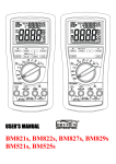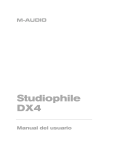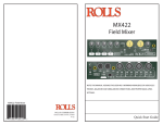
1
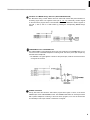
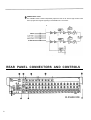
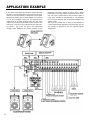
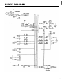
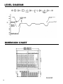
®
YAMAHA
AUTHORIZED
PRODUCT MANUAL
MC-Series Mixing Consoles
YAMAHA
MC-Series Mixing Consoles
Operating Manual
Congratulations!
You are the proud owner of a Yamaha MC-series Mixing Console. Whether you
chose the 8, 12 or 16-channel model, your Yamaha mixing console is a high-quality
product that will give you superior performance in a wide range of applications. In
addition to offering a versatile mixing system, the MC-series consoles offer electronically balanced inputs and stereo outputs to maintain optimum signal quality over
long cable runs, a versatile 3-band equalizer with sweepable mid-frequency EQ on
each input channel, three independent AUX submix systems for external effects
routing or additional power amplifier feeds, cue switches for independent monitoring of all input channels and busses, and a built-in talkback system for convenient
communication.
Of course, the MC-series mixing consoles also offer the high standard of quality and
great sound that Yamaha is famous for. We urge you to read this operation manual
thoroughly in order to make the most of the mixer’s many features and controls.
CONTENTS
PRECAUTIONS . . . . . . . . . . . . . . . . . . . . . . . . . . . .
FRONT PANEL CONTROLS . . . . . . . . . . . . . . . . . .
Input Channels . . . . . . . . . . . . . . . . . . . . . . . . .
Master Control Section . . . . . . . . . . . . . . . . . . .
REAR PANEL CONNECTORS AND CONTROLS . . . .
APPLICATION EXAMPLE . . . . . . . . . . . . . . . . . . . .
BLOCK DIAGRAM . . . . . . . . . . . . . . . . . . . . . . . .
LEVEL DIAGRAM . . . . . . . . . . . . . . . . . . . . . . . . .
2
3
3
6
9
11
12
13
DIMENSION CHART . . . . . . . . . . . . . . . . . . . . . . . . 13
SPECIFICATIONS . . . . . . . . . . . . . . . . . . . . . . . . . . 14
SERVICE . . . . . . . . . . . . . . . . . . . . . . . . . . . . . . . 15
1
PRECAUTIONS
1. AVOID EXCESSIVE HEAT, HUMIDITY, DUST AND
VIBRATION
Keep the unit away from locations where it is likely to be
exposed to high temperatures or humidity–such as near
radiators, stoves, etc. Also avoid locations which are
subject to excessive dust accumulation or vibration which.
could cause mechanical damage.
2. AVOID PHYSICAL SHOCKS
Strong physical shocks to the unit can cause damage.
Handle it with care.
3. DO NOT OPEN THE UNIT OR ATTEMPT REPAIRS OR
MODIFICATIONS YOURSELF
5. HANDLE CABLES CAREFULLY
Always plug and unplug cables–including the AC cord–by
gripping the connector, not the cord.
6. CLEAN WITH A SOFT DRY CLOTH
Never use solvents such as benzine or thinner to clean the
unit. Wipe clean with a soft, dry cloth.
7. ALWAYS USE THE CORRECT POWER SOURCE
Make sure that the power source voltage specified on the
rear panel matches your local AC mains supply.
U.S. & Canadian Models: 120V AC, 60Hz
General Model: 110 — 120/220 — 240 V AC, 50/60Hz
This product contains no user-serviceable parts. Refer all
maintenance to qualified Yamaha service personnel. Opening the unit and/or tampering with the internal circuitry
will void the warranty.
4. MAKE SURE POWER IS OFF BEFORE MAKING OR
REMOVING CONNECTIONS
Always turn the power OFF prior to connecting or disconnecting cables. This is important to prevent damage to
the unit itself as well as other connected equipment.
2
FRONT PANEL CONTROLS
Input Channels
PAD Switch
This switch attenuates the signal applied to the corresponding rear-panel HI-Z or LO-Z input by
20 dB prior to the head amplifier and input gain control. The PAD switch effectively increases
the range of input signal levels that can be handled by the mixer, preventing overloading of the
input circuitry when receiving high-level signals.
GAIN Control
This control adjusts the input sensitivity of each input channel between –60 dB (0.775 mV)
and –20 dB (77.5 mV) when the PAD switch is OFF (between –40 dB and 0 dB when the PAD
switch is ON). Continuously variable gain control allows optimum matching with virtually any
microphone or line source.
CLIP LED Indicator
The CLIP indicator LED lights when the post-EQ signal of the corresponding channel’s input
reaches a level 3 dB below the clipping level of the channel’s circuitry. If the CLIP indicator
lights more than only briefly on high-level transients it is necessary to decrease the input sensitivity of the channel using the GAIN control and PAD switch or, if this does not provide
sufficient attenuation, to reduce the output level of the source connected to that channel’s
input.
3-band Equalizer
The equalizer section provided on each input channel comprises shelving LOW and HIGH controls, and a peaking MID control with a MID FREQ control that permits sweeping the midrange
center frequency from 350 Hz to 5 kHz.
Control
Frequence
Type
HIGH
±15dB
10kHz
Shelving
MID
±15dB
0.35~5kHz
Peaking
100Hz
Shelving
LOW
3
Maximum
Boost/Cut
±15dB
AUX Controls (1,2 & 3)
The MC-series mixing consoles have three independent AUX busses which are fed by the
corresponding AUX controls on the input channels. Each AUX control determines the level of
the signal sent from that channel to the correspondingly numbered AUX mixing buss, which in
turn feeds the correspondingly numbered AUX SEND control and AUX SEND jack on the
console’s rear panel. The AUX controls can be used to determine the amount of signal from the
corresponding input channel sent to external effect devices or power amps fed by the AUX
SEND jacks:
* AUX 1 is factory pre-wired for pre-EQ/pre-fader operation, so the AUX 1 signal is not
affected by the setting of the channel EQ controls or fader. An internal jumper allows the
AUX 1 control to be rewired for post-EQ/post-fader operation.
* AUX 2 and AUX 3 are factory pre-wired for post-EQ/post-fader operation, so the AUX 2
and AUX 3 signals are affected by the setting of the channel EQ controls and fader. Internal
jumpers allow the AUX 1 control to be rewired for pre-EQ/pre-fader operation.
* An internal POST EQ jumper allows the AUX controls to be further re-configured for
post-EQ/pre-fader operation.
* REFER THE ABOVE-MENTIONED REWIRING JOBS TO QUALIFIED YAMAHA SERVICE PERSONNEL!
PAN Pots
The PAN pot determines the position. in the stereo sound field at which the sound from that
channel is heard. Rotated fully counterclockwise the channel signal will be delivered from the
left stereo output only, and will be heard at the far left of the sound field. If the PAN pot is
turned fully clockwise, the sound from that channel will appear at the far right of the stereo
sound field. If the PAN pot is set at its center position, the channel signal will be sent equally
to both the left and right channels, causing the sound to appear at the center of the sound field.
Intermediate PAN pot settings cause the sound to be heard at the corresponding position.
CUE Switch
When the CUE switch is pressed, the pre-EQ/pre-fader signal from that channel is fed to the
PHONES output via the CUE/PHONES level control. The channel cue signal will be added to
any other active cue signal. If you want to monitor only the signal from a single channel, make
sure all other CUE switches are turned OFF.
4
Channel Fader
This is the main level control for each input channel. It determines the level of the signal sent
from the corresponding input channel to the master stereo buss. The settings of the input
channel faders determine the "mix" or balance of sound levels between the instruments or
other sources connected to the inputs.
* If a channel is not being used, its fader should be set to the minimum position to prevent
unwanted noise from being added to the main program signal.
5
Master Control Section
AUX SEND (1, 2 & 3) Controls & CUE Switches
These adjust the overall output level of the auxiliary
"mixes" set up using the AUX 1, AUX 2 and AUX 3 controls on the input channels. AUX SEND 1 sets the overall
level of the AUX 1 mix signal appearing at the AUX
SEND 1 jack, AUX SEND 2 sets the overall level of the
AUX 2 mix signal appearing at the AUX SEND 2 jack,
and AUX SEND 3 sets the overall level of the AUX 3
mix appearing at the AUX SEND 3 jack. These controls
should be used to optimally match the AUX SEND output level of the mixing console to the input sensitivity of
the effect unit, signal processing device or amplifier used.
The CUE switches associated with each AUX SEND control can be used to send the corresponding AUX SEND
signal to the PHONES jack via the CUE/PHONES level
control. The AUX cue signal will be added to any other
active cue signal. If you want to monitor only the signal
from a single AUX buss, make sure all other CUE switches
are turned OFF.
AUX RTN 1 & AUX RTN 2 Controls
These controls adjust the level of the signal received at the
rear-panel AUX RTN jacks and mixed into the main
stereo program. Since stereo AUX returns are provided
(AUX RTN 1 L & R, AUX RTN 2 L & R) the AUX RETURN controls simultaneously adjust the level of the
signals appearing at the corresponding L and R return
inputs. The returned L and R channel signals are sent to
the L and R stereo buss lines. If only a single-channel
signal is returned (i.e. a plug is inserted into only the L or
R return jack), the signal will be fed to both the L and R
channels of the stereo buss.
6
Talkback ON Switch
Pressing this switch activates the talkback microphone plugged into the talkback mic connector,
allowing voice communication from the console operator to the STEREO, AUX 1, AUX 2 or
AUX 3 busses according to the setting of the talkback assignment switches.
TB (Talkback) Level Control
Adjusts the level of the talkback signal sent to the selected buss.
Talkback Microphone Connector
This female XLR type connector accepts just about any standard 50 ~ 600 ohm microphone
for talkback pickup. A gooseneck-type microphone that can be positioned for the most comfortable operation is an excellent choice.
Talkback Assignment Switches (AUX1/AUX2/AUX3/ST)
These switches allow the talkback signal to be fed to the STEREO, AUX 1, AUX 2 or AUX 3
busses. Any number of switches may be ON at the same time, so you can "talk back" to a
number of the console’s busses at once.
7
VU Meters and METER Assign Switches (AUX1/AUX2/AUX3/CUE)
The MC-series mixing console feature three VU meters with built-in LED peak indicators for
monitoring signal levels. The rightmost meter pair (L ST R) continuously monitors signals
on the main stereo program buss. The AUX/CUE meter can be switched to monitor signals on
the AUX 1, AUX 2, AUX 3 or CUE busses by pressing the corresponding METER assign
switch.
CUE/PHONES Control and PHONES Jack
The CUE/PHONES control adjusts the level of the cue signal sent to the PHONES jack so you
can set the most confortable headphone monitoring level. The stereo phone jack accepts any
standard stereo headphones.
* The STEREO cue signal appears in stereo at the phones jack, while the channel and AUX
cue signals are monaural.
STEREO CUE Switch
Turning this switch ON sends the main stereo program buss signal, in stereo, to the stereo
PHONES jack via the CUE/PHONES control. The STEREO CUE switch can normally be turned
ON to permit headphone monitoring of the main stereo program, but it must be turned OFF
to individually monitor input channel or AUX buss cue signals.
8
STEREO Master Faders
The STEREO master faders independently adjust the level of the left and right channel main
stereo program buss signals appearing at the STEREO OUT connectors.
REAR PANEL CONNECTORS AND CONTROLS
9
POWER Switch
Flip up to turn power ON, and down to turn power OFF.
The VU meter lamps will light when the power is ON.
PHANTOM MASTER Switch
Turn this switch ON to apply +48 volts DC to the LO-Z
XLR input connectors when using phantom-powered
condenser microphones.
* NEVER turn the PHANTOM MASTER switch ON
when applying line-sources to the LO-Z inputs.
HI-Z and LO-Z Input Connectors
Each input channel offers a choice of two input connectors: a balanced LO-Z (low-impedance) XLR-type connector and a HI-Z (high-impedance) tip-ring-sleeve 1/4"
phone jack. The LO-Z inputs are primarily intended for
use with professional low-impedance microphones or
electronic instruments having low-impedance balanced
outputs. The HI-Z inputs will accept either balanced or
unbalanced signals from high-impedance microphones,
musical instruments or other source equipment.
INPUT CH INSERT IN/OUT Jacks
These jacks permit inserting compressors, limiters or other
types of external signal processing equipment between the
head amplifier and EQ stage of each input channel. The
jacks are tip-ring-sleeve types in which the tip is SEND
(the output from the head amplifier), the ring is RETURN
(the input to the EQ stage), and the sleeve is ground.
External equipment may be inserted using "Y" cables
which branch the SEND and RETURN lines from a tipring-sleeve phone plug to two separate mono phone plugs.
AUX SEND (1, 2 & 3) Jacks
These jacks deliver the AUX 1, AUX 2 and AUX 3 mixes,
respectively, to feed an external effect device or power
amplifier. Nominal output level/impedance is +4 dB/
600 ohms.
AUX RETURN 1 (L & R) & AUX RETURN 2 (L & R)
Jacks
The mono or stereo output from effect units fed by the
AUX SEND jacks can be returned to the main stereo
program mix via these jacks. Note that each AUX RETURN offers independent return inputs for the left and
right busses, accommodating the return signal from effect
units featuring stereo outputs. Nominal input level/impedance is +4 dB/600 ohms.
AUX SUB IN & ST SUB IN Jacks
These five jacks permit "cascading" two MC-series mixing
consoles to increase the number of available input channels. The AUX OUT jacks from the first (slave) console
should be connected to the corresponding AUX SUB IN
jacks of the second (master) console, and the STEREO
outputs from the slave console should be connected to the
corresponding ST SUB IN jacks on the master console.
STEREO OUT L & R Connectors
The MC-series mixing consoles provide balanced XLR connector outputs from the main stereo buss. The signal
delivered is a stereo mix of the input channel signals and
the signals returned to the AUX RETURN jacks. The
STEREO OUT signal will normally be used to drive a
power amplifier and speaker system, powered keyboard
speakers or a main house mixing console. Nominal output
level/load impedance is +4 dB/600 ohms.
NOTE: The MC-series mixing console XLR connectors are
wired according to DIN specifications. Pin 1 is
shield (ground), pin 2 is hot (signal high) and pin 3
is cold (signal low).
10
APPLICATION EXAMPLE
In the system shown below the MC1602 is used as the main
console in a sound reinforcement system. Three vocal microphones, six drum microphones, a microphone from the guitar
amplifier and another from the bass amplifier are connected
to 11 of the 16 available LO-Z inputs. The line-level stereo
outputs from an on-stage keyboard mixer and the stereo
outputs from an electronic percussion system are fed to four
HI-Z inputs. A total of 15 input channels are thus used, leaving one free — just in case. The AUX 1 mix system feeds
on-stage power amplifiers and monitor speakers for the
11
performers. The AUX 2 system is used to drive a digital
reverb/effects unit to add ambience and effects where necessary. The AUX 3 system feeds a tape recorder to make a
rough mono recording of the performance. The STEREO
OUT connectors drive the main house power amplifiers and
speaker system.
This is just one possible way of setting up the MC1602 for
a sound reinforcement application. The actual setup you use
will, naturally, be dictated by your own particular system
requirements.
BLOCK DIAGRAM
12
LEVEL DIAGRAM
DIMENSION CHART
13
SPECIFICATIONS
Total Harmonic
Distortion
Less than 0.1%, 20Hz – 20kHz @ +14dB
into 600 ohms.
Frequency Response
+1, –3dB, 20Hz – 20kHz @ +4dB into
600 ohms
Hum and Noise* (20Hz –128dB equivalent input noise.
– 20kHz, Rs=150 ohms, –90dB residual output noise (balanced
Input Gain max., Input
outputs).
Pad @ 0dB, Input
–73dB at STEREO OUT with master
Sensitivity –60dB)
fader at nominal level and all
channel faders at minimum level.
–64dB at STEREO OUT with master
fader and one channel fader at
nominal level
–70dB at AUX SEND with AUX SEND
level control at nominal level
and all channel AUX controls at
minimum level.
–64dB at AUX SEND with AUX SEND
and, one AUX control at nominal
level,
Maximum Voltage Gain 84dB
84dB
94dB
20dB
10dB
10dB
CH IN to STEREO OUT
CH IN to AUX SEND 1
CH IN to AUX SEND 2, 3
AUX RETURN 1, 2 to STEREO OUT
SUB IN to AUX SEND 1 – 3
SUB IN to STEREO OUT
Phantom Power
+48 VDC applied to electronically balanced inputs via 6.8 k-ohm
limiting resistors. Master ON/OFF switch.
Power Requirements
U.S.&Canadian models: 120V AC, 60Hz
110 – 120/220 – 240V AC, 50/60Hz
General model:
Power Consumption
MC1602:
MC1202:
MC802:
60 watts
60 watts
40watts
Dimensions (W x H x D)
MC1602: 730 mm x 151 mm x 531 mm
(28-3/4” x 6” x 20-7/8”)
MC1202: 590 mm x 151 mm x 531 mm
(23-1/4” x 6” x 20-7/8”)
MC802: 450mm x 151 mm x 531 mm
(17-3/4” x 6” x 20-7/8”)
Weight
MC1602: 18 kg. (39.7 Ibs.)
MC1202: 15 kg. (33.1 Ibs.)
MC802: 12 kg. (26.4 Ibs.)
* Measured with a –6dB/octave LPF @ 12.7kHz.
• 0dB = 0.775Vr.m.s.
• Specifications subject to change without notice.
Input Channel Gain Control
–20
–60dB variation in gain, stop to stop.
~
Input Channel Pad Switch
0/20dB of attenuation.
Input Channel Equalization
15dB maximum boost or cut in each of three bands.
HIGH: 10kHz (shelving)
MID: 350Hz – 5kHz (peaking)
LOW: 100Hz (shelving)
Crosstalk
–60dB at 1 kHz, adjacent input channels.
–60dB at 1 kHz, input to output.
VU Meters (0 VU = +4dB Output)
3 illuminated meters,
STEREO L, STEREO R, AUX1/AUX2/AUX3/CUE (switchable)
Clip Indicators
RED LED built into each input channel. Lights when post-EQ
channel signal is 3dB below clipping level.
14
INPUT CHARACTERISTICS
n
INPUT
PAD
CH INPUT
OFF(0dB)
ON(20dB)
INPUT
SOURCE
IMPEDANCE IMPEDANCE
GAIN
SENSITIVITY**
50 ~ 600 ohms –80dB (0.08mV)
Microphones
–40dB (7.75mV)
or
–20dB HI-Z 10k ohms
600 ohms Lines –20dB (77.5mV)
–60dB
LO-Z 4k ohms
INPUT LEVELS
MAXIMUM
NON CLlPPING
RATED LEVEL
LEVEL
–60dB (0.8mV)
–34dB (15.5mV)
–20dB (77.5mV)
–0dB (775mV)
+6dB (1.65V)
+26dB (15.5V)
INPUT CH INSERT lN
10k ohms
600 ohms Lines –26dB (38.8mV)
–6dB (388mV)
+20dB (7.75V)
ST SUB IN, AUX SUB IN
10k ohms
600 ohms Lines
–6dB (388mV)
+4dB (1.23V)
+20dB (7.75V)
AUX RTN
10k ohms
600 ohms Lines –16dB (123mV)
+4dB (1.23V)
TALKBACK IN
n
4k ohms
50 ~ 600 ohms
Microphones
–70dB (0.25mV)
XLR-3-31 type
( Balanced)
and
Phone Jack (TRS)
(Balanced)
Phone Jack (TRS)
(Unbalanced)
Phone Jack
(Unbalanced)
–
–50dB (2.45mV)
–24dB (48.9)
Phone Jack
(Unbalanced)
XLR-3-31 type
(Unbalanced)
OUTPUT CHARACTERISTICS
OUTPUT
OUTPUT LEVELS
OUTPUT
IMPEDANCE
LOAD IMPEDANCE
150 ohms
RATED LEVEL
MAXIMUM NONCLIPPING LEVEL
CONNECTOR TYPE
600 ohms Lines
+4dB (1.23V)
+24dB (12.3V)
XLR-3-32 type
(Balanced)
150 ohms
600 ohms Lines
+4dB (1.23V)
+20dB (7.75V)
INPUT CH INSERT OUT
600 ohms
10k ohms Lines
–6dB (388mV)
+20dB (7.75V)
PHONES
100 ohms
8 ohms Phones
40 ohms Phones
1mW
20mW
3mW
130mW
ST OUT
AUX SEND 1
3
** Input level required to produce rated +4dB output level.
• 0dB = 0.775Vr.m.s.
SERVICE
This product is supported by Yamaha’s worldwide network of
factory trained and qualified dealer service personnel. In the event
of a problem, contact your nearest Yamaha dealer.
15
CONNECTOR
TYPE
Phone Jack
(Unbalanced)
Phone Jack (TRS)
(Unbalanced)
Stereo Phone Jack
(Unbalanced)
YAMAHA
®
Yamaha Corporation of America
6600 Orangethorpe Avenue, P.O. Box 6600, Buena Park, CA 90622-6600
12/2/96