1
Model 400
B/W Reflection
Densitometer
Operation Manual
Dear Customer:
Congratulations! We at X-Rite, Incorporated are proud to present
you with the X-Rite 400 B/W Reflection Densitometer. This
instrument represents the very latest in microcontrollers, integrated
circuits, optics, and display technology. Your X-Rite 400 is a
rugged, reliable, finely engineered instrument whose performance is
unsurpassed.
To fully appreciate and protect your investment, we suggest that you
take the necessary time to read and fully understand this manual. As
always, X-Rite stands behind your 400 with a full one year limited
warranty and a dedicated service organization. If the need arises,
please don’t hesitate to call us.
Thank you for your trust and confidence.
X-Rite, Incorporated
i
CE DECLARATION
Manufacturer's Name:
Manufacturer's Address:
X-Rite, Incorporated
3100 44th Street, S.W.
Grandville, Michigan 49418
U.S.A.
Model Name:
Model No.:
Densitometer
400
Directive(s) Conformance:
EMC 89/336/EEC LVD 73/23/EEC
NOTE: The device complies to the product specifications for the Low Voltage
Directive when furnished with the 230VAC AC Adapter (X-Rite P/N SE30-62),
and to UL Standards when furnished with the 115VAC AC Adapter
(X-Rite P/N SE30-61).
ii
FEDERAL COMMUNICATIONS COMMISSION NOTICE
FCC Statement
This equipment has been tested and found to comply with the limits
for a Class A digital device, pursuant to Part 15 of the FCC Rules.
These limits are designed to provide reasonable protection against
harmful interference when the equipment is operated in a
commercial environment. This equipment generates, uses, and can
radiate radio frequency energy and, if not installed and used in
accordance with the instruction manual, may cause harmful
interference to radio communications. Operation of this equipment
in a residential area is likely to cause harmful interference in which
case the user will be required to correct the interference at his own
expense.
Canada
This Class A digital apparatus meets all requirements of the
Canadian Interference-Causing Equipment Regulations.
Cet appareil numérique de la classe A respecte toutes les exigences
du Règlement sur le matériel brouilleur du Canada.
The Manufacturer:
Der Hersteller:
El fabricante:
Le fabricant:
Il fabbricante:
X-Rite, Incorporated
3100 44th Street, S.W.
Grandville, Michigan 49418
Declares that:
gibt bekannt:
advierte que:
avertit que:
avverte che:
Densitometer
400
is not intended to be connected to a public telecommunications network.
an ein öffentliches Telekommunikations-Netzwerk nicht angeschlossen werden soll.
no debe ser conectado a redes de telecomunicaciones públicas.
ne doit pas être relié à un réseau de télécommunications publique.
non deve essere connettuto a reti di telecomunicazioni pubblici.
iii
CAUTION: Operational hazard exists if AC adaptor other than
X-Rite SE30-61 (115V) or SE30-62 (230V) is used.
VORSICHT: Betriebsgefahr besteht bei Gebrauch von anderen
Adaptern als X-Rite SE30-61 (115 U) oder SE30-62 (230 U).
AVISO: No use otro adaptador C.A. que no sea la pieza X-Rite
SE30-61 (115V) o SE30-62 (230V), por el riesgo de mal
funcionamiento del equipo.
ATTENTION: Ne pas utiliser d’adaptateur autre que SE30-61
(115V) ou SE30-62 (230V) de X-Rite au risque de mauvais
fonctionnement de l’appareil.
AVVISO: Non usare un altro adattatore C.A. che non è del pezzo
X-Rite SE30-61 (115V) o SE30-62 (230V), per il rischio di
malfunzionamento dell’apparecchio.
NOTE: Shielded interface cables must be used in order to
maintain compliance with the desired FCC and European emission
requirements.
iv
WARNING: This instrument is not for use in explosive
environment.
WARNUNG: Das Gerät darf in einer explosiven Umgebung
NICHT verwendet werden.
ADVERTENCIA: NO use este aparato en los ambientes explosivos.
ATTENTION: Cet instrument NE DOIT PAS être utilisé dans un
environnement explosif.
AVVERTIMENTO: NON usare questo apparecchio in ambienti
esplosivi.
USE ONLY: AA NICad batteries that are 600/700mAhr rated, six
required. Other types may burst causing personal injury.
VORSICHT: Verwenden Sie nur AA NiKad Akkus von
600/700mAhr (Milliampere/Stunde) Nennstrom, 6 Stück
erforderlich. Mit anderen Akkus besteht Explosions- und
Verletzungsgefahr.
ATENCION: Use solamente las pilas de AA NiCad (se requiere
seis) con condiciones de funcionamiento normales 600/700mAhr
(horas miliamperios). Es posible que los otros tipos puedan estallar y
causar daños corporales.
ATTENTION: Utiliser seulement les batteries NICad à courant
nominal de 600mAh (milliampère/heure) (6 pièces nécessaire). Il y
a danger d'explosion et de blessures avec les autres types.
ATTENZIONE: Usare solamente gli accumulatori al AA NiCad (si
richiede sei) con le condizioni di funzionamento normali
600/700mAhr (ore milliamperi). E possibile che altri tipi possano
scoppiare e causare danno personale.
v
Contents
vi
1
Overview and Setup
Features............................................................................ 1-1
Packaging and Parts ............................................................ 1-3
Instrument Vocabulary ...................................................... 1-4
Unlocking/Locking the Shoe .............................................. 1-5
Batteries and Power .......................................................... 1-6
Adjusting the Display Angle............................................... 1-9
I/O Port Setup ................................................................... 1-10
2
Calibration
Response Settings ............................................................ 2-1
Overview of Calibration Procedures .................................. 2-2
Long Calibration ................................................................ 2-3
Quick-Cal™ ...................................................................... 2-4
3
Density Functions
Selecting Density Function ................................................ 3-2
Density Measurement........................................................ 3-2
Density Difference Measurement ...................................... 3-3
Miscellaneous Display Messages ...................................... 3-4
4
Dot Functions
Dot Formula ...................................................................... 4-1
Selecting Dot Area or Dot Gain ......................................... 4-4
Dot Area Function ............................................................. 4-5
Dot Gain Function ............................................................. 4-7
5
Range Functions
Reference Value ............................................................... 5-1
Absolute Range Measurement .......................................... 5-2
Range Minus Reference Measurement.............................. 5-2
6
Technical Information
Serial Interface Information ............................................... 6-1
Instrument Specifications .................................................. 6-4
Accessories....................................................................... 6-6
General Cleaning .............................................................. 6-7
Optics Maintenance........................................................... 6-7
Target Window Replacement ............................................ 6-8
Lamp Replacement ........................................................... 6-9
7
Appendices and Index
Proprietary Notice ............................................................. 7-1
Limited Warranty............................................................... 7-2
Index................................................................................. 7-3
Copyright 1998 by
X-Rite, Incorporated
“ALL RIGHTS RESERVED”
X-Rite is a registered trademark and Quick Cal™, Q Cal™, Electronic Function
Selection™, Computerized Color Response™, and CCR™, are trademarks of X-Rite,
Incorporated. All other logos, brand names, and product names are the properties of their
respective holders.
vii
viii
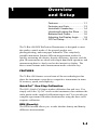
1
Overview
and Setup
Features ................................... 1-1
Packaging and Parts.................... 1-3
Instrument Vocabulary.............. 1-4
Unlocking/Locking the Shoe...... 1-5
Batteries and Power.................. 1-6
Adjusting the Display Angle ...... 1-9
I/O Port Setup..........................1-10
The X-Rite 400 B/W Reflection Densitometer is designed to meet
the quality control needs of the general graphic arts,
phototypesetting, and newspaper industries. This completely
portable instrument features different measurement modes for
quickly measuring ink density, density difference, dot area, and dot
gain. Measurements are taken with simple hand-held operation, and
measurement data is clearly read on the interactive display. The
three control buttons make measurement mode selection easy.
FEATURES
The X-Rite 400 features several state-of-the-art technologies that
place the instrument a step above competitive instruments in terms
of accuracy, speed, and simplicity:
QuickCal™ One-Step Calibration
The 400’s Quick-Cal feature makes calibration fast and easy. You
simply select the “Q-Cal” mode on the instrument, then measure the
white patch on the supplied calibration target card. You can also get
complete agreement with other densitometers using the three-color
response calibration.
DEN (Density)
The DEN function allows you to take absolute density and density
difference measurements.
1-1
400 B/W Reflection Densitometer
DOT
The DOT function allows Dot area and Dot gain measurements. Dot
is calculated with paper subtracted out using the Murray-Davies or
Yule-Nielson formulas.
Range
Range subtracts the lowest measurement from the highest and
displays the difference. Range-Reference subtracts a reference value
from the range and displays the difference.
Nonvolatile Memory
A lithium battery stores calibration data and measured values when
the densitometer’s primary rechargeable batteries are depleted or
removed.
Additional Features
Ÿ Large LCD display clearly identifies measurement data and
mode function. No need for numeric codes to identify this
information.
1-2
Ÿ
Three large buttons place all function controls at operator’s
fingertips.
Ÿ
AC adapter is provided to allow readings while batteries are
being recharged.
Ÿ
Two-way RS-232 interface operates at 1200 baud, or one of
several other baud rates.
Overview and Setup
PACKAGING AND PARTS
After removing the instrument from the shipping carton, inspect for
possible damage. If any damage is noted, contact the transportation
company immediately. Do nothing more until the carrier’s agent has
inspected the damage.
If damage is not evident, check to ensure that all items are included
(refer to the parts list below).
Your Package Should Include…
1 400 B/W Reflection Densitometer
1 Carrying Case
1 Operation Manual
1 Reflection Calibration Reference 400-62
1 Warranty Registration Card
1 P/N SE30-61 Battery Charger, 115V
or P/N SE30-62 Battery Charger, 230V
1 P/N SD01-41 Certificate of Calibration
Along with this Operation Manual, several important notices are
included. You should read each of these notices before using the
instrument.
Return Packaging
Your X-Rite 400 was packaged in a carton specially designed to
prevent damage. If re-shipment is necessary, the instrument should
be re-packaged in the original carton. If the original carton is not
available, a new one can be obtained from X-Rite.
1-3
400 B/W Reflection Densitometer
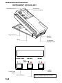
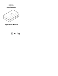
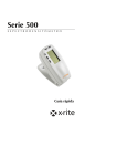
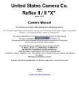
INSTRUMENT VOCABULARY
3 Operating Keys
8-character
Interactive Display
Target Window
RS232
I/O Port
Shoe
FUNCTION
ENTER
ZERO
ZERO
Button
FUNCTION
Button
ENTER Button
1-4
AC Adapter
(Charger) Jack
Arrows indicate button’s function for
adjusting display values up or down.
Overview and Setup
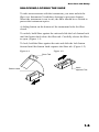
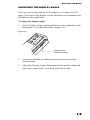
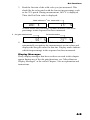
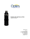
UNLOCKING/LOCKING THE SHOE
To take measurements with the instrument, you must unlock the
Shoe (see Instrument Vocabulary drawing in previous chapter).
When the instrument is not in use, the Shoe should be re-locked to
protect the instrument optics.
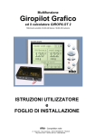
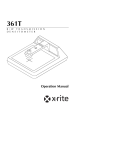
A sliding button on the bottom of the instrument locks the Shoe
closed.
To unlock, hold Shoe against the unit and slide the lock button back
until the button latch clears the Shoe tab. Carefully release the Shoe
to open. (Figure 1-1)
To lock, hold the Shoe against the unit and slide the lock button
forward until the button latch captures the Shoe tab. (Figure 1-2)
Figure 1-1
Figure 1-2
Shoe Tab
Button Latch
Latch
captures Tab
1-5
400 B/W Reflection Densitometer
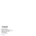
BATTERIES AND POWER
Your 400 instrument’s batteries should be charged before use. It can
be operated while the batteries are being charged.
Before you begin charging, you must remove the battery isolation
insert protruding from the battery cover. (Figure 1-3)
Figure 1-3
Battery Isolation Tab
NOTE: Make sure the voltage indicated on the AC adapter complies
with the AC line voltage in your area. If it does not, contact your
X-Rite dealer.
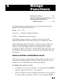
To charge the battery:
1.
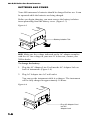
Plug the AC Adapter Line Cord into the AC Adapter Jack on
back of instrument. (Figure 1-4)
2.
Plug AC Adapter into AC wall outlet.
You can use the instrument while it recharges. The instrument
will be fully charged in approximately 14 hours.
Figure 1-4
Plug AC Adapter Cord
into AC
Adapter Jack
1-6
Overview and Setup
NOTE: If your unit has not been used for several weeks recharge for
approximately 24 hours.
NOTE: When storing the unit for a long period of time, the
batteries should be removed.
Applying Power
The instrument remains “powered down” until a measurement is
taken. When a measurement is taken, or when any key is pressed,
the instrument automatically turns on.
If no measurements are taken or keys pressed for 45 seconds, the
instrument automatically turns off again to conserve battery power.
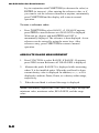
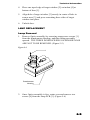
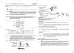
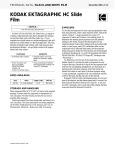
Inserting/Removing the Batteries
Your instrument is shipped with six AA NI-CAD batteries already
installed. Should you ever need to replace the batteries, first close
and lock the Shoe (when the shoe is unlocked and open, it blocks
the battery door). Next, slide the battery door in the rear of the
instrument down and off. The batteries will spring out a bit.
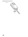
To replace the batteries, insert six fresh AA NI-CAD batteries into
the instrument, three into each chamber. Note the proper polarity
of the batteries in Figure 1-5, and on the CAUTION label
beneath the instrument. You will need to press and hold the
batteries down in place while you slide the battery cover back on.
Push the cover into place until it is flush with the bottom of the
instrument.
1-7
400 B/W Reflection Densitometer
Figure 1-5
1-8
Overview and Setup
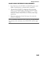
ADJUSTING THE DISPLAY ANGLE
You can most clearly read the LCD display by viewing it at a 90º
angle. The angle of the display can be adjusted to accommodate this
for different user sight lines.
To adjust the display angle:
1.
Set the Display Angle Adjustment Knob on the right side of the
instrument to its midpoint setting. (Figure 1-6)
Figure 1-6
Display Angle
Adjustment Knob
2.
Activate the display by taking a measurement or pressing a
control button.
3.
Adjust the Display Angle Adjustment Knob until the displayed
data can be most clearly seen from your line of sight.
1-9
400 B/W Reflection Densitometer
I/O PORT SETUP
Your X-Rite 400 has a serial port that allows data to be transmitted
toor received from an external device. With this I/O connection
made, the 400 can controlled externally by Serial Input Commands.
If you do not plan to use the I/O port at this time, you can skip
ahead to Chapter 2, “Calibration.”
You can configure different functions of your I/O port using the
instrument’s MODE selection procedures. You can set up:
Ÿ
Ÿ
Ÿ
The desired Baud rate (output rate of characters per second) for
transmitting data via the I/O port;
the desired header (HDR) that will appear above the transmitted
or printed data; and
the desired computer output format (COMP).
To set up the I/O port:
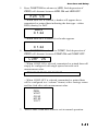
1.
Press the FUNCTION button and the ENTER button
simultaneously, then release.
N cal X Y appears in the display, where “X” represents the
installed response (B or R).
N calX Y
2.
Press FUNCTION to indicate no, you do not want to calibrate.
N mode Y appears in the display.
N mode Y
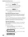
3.
Press ZERO to indicate yes, you do want to set mode. ↓ I/O Y
appears in the display.
^ I/O
4.
Y
Press ZERO to indicate yes, you do want to set I/O Ports. Each
depression of ZERO will alternate between Aenter and Menter
^ Aenter
When Aenter is selected, data is automatically transmitted at
the end of each measurement.
When Menter is selected, data is manually transmitted after
a measurement by pressing SEND.
1-10
Overview and Setup
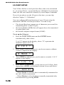
5.
Press FUNCTION to advance to HDR. Each depression of
ZERO will alternate between HDR ON and HDR OFF.
HDR ON
When HDR ON is selected, a header will appear above
transmitted or printed data indicating the data typeeither
DEN (density) or DOT.
DEN
C 1.24
—When HDR OFF is selected, no header appears.
C 1.24
6.
Press FUNCTION to advance to COMP. Each depression of
ZERO will alternate between COMP ON and COMP OFF.
COMP ON
When COMP ON is selected, transmitted or printed data will
simply be configured with single spaces between each
measurement value.
DEN V0.67 C0.20 M1.23 Y0.77
When COMP OFF is selected, transmitted or printed data
will be configured in a “column” format, with a carriage return
and line feed after each measurement value.
DEN
V0.67
C0.20
M1.23
Y0.77
7.
Press FUNCTION three times to exit to normal operation.
1-11
400 B/W Reflection Densitometer
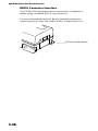
RS232 Connector Interface
Your X-Rite 400 instrument can be connected to a computer or
printer using a standard RS232 9-pin connector.
For more information on Serial Input Commands and remote
control operation of the 400 contact X-Rite Technical Services.
I/O Port for Serial Interface
1-12
2
Calibration
Response Settings.................... 2-1
Overview of Calibration
Procedures ............................... 2-2
Long Calibration ....................... 2-3
Quick-Cal™.............................. 2-4
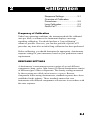
Frequency of Calibration
Under long operating conditions, the instrument should be calibrated
once per week, or whenever the instrument displays a message
regarding calibration. You should perform a “long calibration”
whenever possible. However, you can also perform a Quick-Cal™
procedure any time after an initial long calibration has been performed.
Before calibrating, you should determine the appropriate densitometer
response setting for your instrument, based on your production control
requirements.
RESPONSE SETTINGS
A densitometer’s measurement system consists of several different
components (lamp, optics, light sensor). Different densitometers consist
of different types of these components. The density readings measured
by these systems are called a densitometer response. Because
components differ among densitometers, standard responses have been
established in the industry. These standards ensure that even
instruments with different components will measure in accordance with
the same response.
2-1
400 B/W Reflection Densitometer
Descriptions of Available Responses
There are two basic versions of the 400, the 400B and the 400R. The
400B allows B-Response. The 400R allows R-Response.
B –X-Rite “Orthochromatic” Response This response is blue-green
sensitive with insensitivity to red light, making it ideal for use in
analyzing color prints for exposure to orthochromatic film. This is also
the response generally used for typesetting and B/W printing
operations.
R –X-Rite “Red” Response This response has a narrow bandwidth
with a peak wavelength of approximately 620nm. This response is
ideally suited for use with red laser flatbed scanners.
There is separate memory to store calibration for both responses. If you
change optics, recalibration must be performed using that response.
Once you have calibrated to both responses, you do not have to
recalibrate when changing optics.
OVERVIEW OF CALIBRATION PROCEDURES
Calibrating your instrument is crucial to maintaining its measurement
stability. It is also important to maintaining measurement agreement
between several densitometers at the same site; and making all
densitometers calibrate precisely to the same standard reference. Your
400 instrument allows you to use two different calibrations procedures
to address these factors:
2-2
1.
Long Calibration will be used before you take your first
measurements for each response. After this calibration procedure
has been performed, you can use Quick-Cal™ (see below) to
quickly re-calibrate when necessary.
2.
Quick Cal™ allows you to quickly re-calibrate to white without
having to re-measure the black.
Calibration
LONG CALIBRATION
1.
If this is your first time calibrating, you should plug your
instrument in using its AC adapter. This will prevent the
microprocessor from going into “sleep” mode to save battery
power. With the instrument plugged in, you’ll be free to take your
time learning this procedure.
2.
Unlock the Shoe.
3.
Press the FUNCTION and ENTER buttons simultaneously until N
calX Y appears in the display. X stands for the default optic.
N calX Y
4.
Press ZERO to indicate Yes, you do want to calibrate.
N Qcal Y
4.
Press FUNCTION to select long calibration. SET LO appears in
the display for a moment.
SET LO
5.
Enter the low value of the WHITE patch from the reference using
the arrow buttons.
To lower the value:
Press and hold the ZERO (ts) button, then press FUNCTION
(t) repeatedly to lower the value until the correct value is shown.
To raise the value:
Press and hold the ZERO (ts) button, then press ENTER (s)
repeatedly to raise the value until the correct value is shown.
TIP: If you need to move the value up or down by a large amount,
hold the (ts) button and (t) or (s) button down. The numbers
will advance faster as you hold it down.
8.
Release all buttons, then press ENTER. SET HI is momentarily
displayed.
9.
Use the arrow buttons to enter the high value of BLACK patch
from the reference.
10. Presss ENTER to advance.
2-3
400 B/W Reflection Densitometer
16. Read patches on the Reference.
17. Place the instrument target window crosshairs over the alignment
marks on the white target patch, then lower the head down onto the
shoe. A filter value appears in the display and READ BLK
(BLACK) appears. Then read the black target patch.
18. The values that appear for each Step measurement should match
the values listed on the envelope for that Step. If they do not, repeat
the calibration procedure. If discrepancies continue to exist, contact
X-Rite Instrument Services.
If all values were correct, your instrument is calibrated!
QUICK CAL™
Once you have performed the long calibration, you can simply perform
the Quick Cal™ procedure periodically to set the low density (white)
value.
NOTE: In most cases, you should simply perform an entire long
calibration if possible.
1.
Press FUNCTION and ENTER simultaneously, then release. N
calX Y appears in the display. X stands for the default optic; if you
have a different response selected, its initial letter will appear in
this position. (See “Selecting Response” earlier in this chapter.)
2.
Press ZERO to indicate yes, you do want to calibrate.
3.
Press ZERO to select Quick Cal™ procedure.
4.
Read Step 1the white patchon the reference card.
Your instrument is calibrated!
Display Messages
If any display messages that have not been covered in this chapter
appear during any of the calibration procedures, see “Miscellaneous
Display Messages” at the end of Chapter 3 for an explanation and
instructions.
2-4
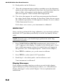
3
Density
Functions
Selecting Density Function ....... 3-2
Density Measurement ............... 3-2
Density Difference
Measurement............................ 3-3
Miscellaneous Display
Messages ................................. 3-4
Your 400 instrument can be used for density measurement
functions, for dot area and dot gain measurement functions, and for
calculating measurement range. This chapter covers density
functions, and the following chapters cover dot and range functions,
respectively.
For density measurement, you need to set some measurement
parameters. You need to select:
Ÿ
Ÿ
the desired measurement function (density); and
the desired density measurement modeabsolute density, or
density minus reference
These parameters must be set for all types of density measurement.
Once these parameters are set, you can set your instrument to
evaluate measurement data two different ways:
Ÿ
Ÿ
As a straight density measurement data. Viewing this data
requires no additional setup.
or
As a density difference measurement data. This data shows you
the amount of difference between the measured density and a
pre-set reference density. To view data in this format, you need
to establish a reference measurement, and set up the instrument
for density difference readings (page 3-3).
3-1
400 B/W Reflection Densitometer
SELECTING DENSITY FUNCTION
1.
If this is your first time selecting a measurement function and
mode, you should plug your instrument in using its AC adapter.
This will prevent the microprocessor from going into “sleep”
mode to save battery power. With the instrument plugged in,
you’ll be free to take your time learning this procedure.
2.
Next, make sure you have the desired response setting selected,
and that the instrument is properly calibrated. These procedures
are covered in the previous chapter, “Calibration.”
3.
To select the measurement method for measuring ink density,
press the FUNCTION button repeatedly until DEN appears in
the display. If the density minus reference measurement is
necessary, press ZERO to turn Reference on. DEN-R appears
on the screen.
DEN -R
DENSITY MEASUREMENT
You are now ready to begin taking measurements to check density
values on your press sheet gray scale. The type of measurement data
that will be displayed will depend on the way you set up your
instrument earlier in this chapter. However, for all functions, modes,
and methods, the measurement technique is the same. Simply:
3-2
1.
Center target window over area to be measured.
2.
Lower unit to target window and hold closed.
3.
Once measurement data is displayed, release the unit.
4.
Measurement data will appear either as a normal density value
(absolute or minus reference) or difference value.
Density Functions
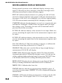
DENSITY DIFFERENCE MEASUREMENT
Density difference measurement uses the same parameters as density
measurement. To set up for density difference measurement, follow
the procedures earlier in this chapter for selecting density function,
mode, and color measurement method.
To view measurement data as a density difference value between a
measured sample and a known referenceinstead of the density
value of the measured sampleyou must first enter a reference
measurement; and then activate the density difference (DEN-R)
display format.
Entering a Reference Measurement
1. Press FUNCTION until DEN appears in the display. After a
moment, a value for one a previous measurement appears in the
display.
2.
Press ZERO. REF appears for a moment, followed by the
current Reference value. If none has been entered, the Reference
value is 0.00.
3.
To enter a reference valueor change the current reference
valueyou can either:
measure the reference value directly; or
manually enter the reference value using the arrow button
functions.
To measure the reference value directly:
Measure the color that you wish to use as the reference. Then,
press FUNCTION to return to normal operation.
To enter the reference value manually:
Hold down the ZERO (ts) button, then press the
FUNCTION (t) or CAL (s)button to adjust the value until the
desired value is shown. Then, press FUNCTION to return to
normal operation.
TIP: If you need to move the value up or down by a large
amount, hold the arrow button down. The numbers will advance
faster as you hold it down.
4.
Measure patch that is to be compared. DEN X is displayed
during measurement, where X is the installed optics.
3-3
400 B/W Reflection Densitometer
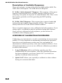
MISCELLANEOUS DISPLAY MESSAGES
During normal operation, some additional display messages may
appear. Following are these messages, what these messages mean
and what action must be taken when they appear.
BAT LO indicates that the batteries are getting low and will soon
need to be charged. BAT LO only appears while the measurement is
in progress. Once BAT LO is displayed, you will have approximately
100-200 measurements remaining before charging is required.
CHARGE indicates that the batteries are too low to operate the unit
and must be recharged. CHARGE does not appear until you begin
the recharge cycle. Thereafter, the unit will be functional and all
previous data will be accessible.
D TOO HI indicates density value measured is too high. Make sure
you are measuring the right color for the measurement sequence and
try again.
D TOO LO indicates density value measured is too low. Make sure
you are measuring the right color for the measurement sequence and
try again.
If D TOO HIGH or D TOO LO continues to appear, re-calibrate the
instrument using long calibration (see Chapter 2).
INVALID When the unit is not held down long enough during a
measurement, INVALID will display.
LAMP FAIL Measurement lamp has failed. The lamp should be
examined and replaced. When this message occurs, you can get out
of this condition (after replacing lamp) by pressing DEN/DOT then
COLOR then DEN/DOT or waiting until unit powers down.
MEM LOST (Displayed only during power-up) Internal lithium
battery is failing. Intermittent connection on Ni-Cad batteries.
NEED CAL Calibration has been lost.
PAPER Indicates that the next measurement should be paper. If
you do not measure paper, PAPER ? Z will be displayed during the
measurement.
PAPER ? Z Displayed during measurement. At this point the 400
is asking if this is a new paper value. If it is a new paper value,
3-4
Density Functions
momentarily press ZERO before releasing the read head. If no,
release the read head and the display will show normal operation.
SOLID Indicates that a measurement on a Solid Ink density is
necessary. The SOLID should be measured first followed by the
appropriate TINT.
SOLID? Z The 400 is asking if the area measured is a Solid. This
message appears when measuring a Dot value of 80% or greater,
and ZERO is depressed. If the area measured is intended to be a
Solid, momentarily press ZERO before releasing the read head. If
not, release the read head and the Dot value is displayed.
3-5
400 B/W Reflection Densitometer
3-6
4
Dot Functions
Dot Formula ............................. 4-1
Selecting Dot Area or Dot Gain. 4-4
Dot Area Function..................... 4-5
Dot Gain Function..................... 4-7
For dot measurements, you need to set some measurement
parameters. You need to select:
Ÿ
Ÿ
Ÿ
The desired formula for dot measurementsthe Murray-Davies
formula or the Yule-Nielson formula (page 4-1); and
the desired measurement functiondot area or dot gain
(page 4-3);
NOTE: All dot function measurements are minus paper.
SELECTING DOT FORMULA
Dot is calculated using the either the Murray-Davies formula or the
Yule-Nielson formula. The Murray-Davies simply calculates dot by
comparing the density of the tint minus paper with the density of
the solid minus paper. Your 400 defaults to the Murray-Davies
formula for measurements.
The Yule-Nielson formula is similar to Murray-Davies, except that
it allows you to compensate for the amount of light that is absorbed
or “trapped” when a dot measurement is taken. This is done by first
dividing the densities of the paper and the solid by an “n” factor.
Using the Murray-Davies equation, your 400 instrument “n” factor
is simply 1.00, so the paper and solid densities are not affected.
Using Yule-Nielson, the paper and solid densities are multiplied by
an “n” factor value that is based on the properties of the substrate
material.
4-1
400 B/W Reflection Densitometer
The Murray-Davies formula for calculating Dot is:
1 - 10
- ( Dt )
x1 0 0
1 - 1 0 - (Ds)
Where: Dt = Density of tint minus density of paper
Ds = Density of solid minus density of paper
Apparent Dot Area =
The Yule-Nielson formula for calculating Dot is:
1- 1 0
- ( Dt )/ n
x1 0 0
- Ds / n
1- 1 0 ( )
Where: Dt = Density of tint minus density of paper
Ds = Density of solid minus density of paper
n = “n” Factor
Apparent Dot Area
=
Selecting Murray-Davies Formula
If you wish to use the Murray-Davies formula, you do not have to
make any modifications to the factory-preset mode settings. When
Murray Davies is active, dot values are displayed as percentages,
with a “%” sign.
If you set your instrument to use Yule Nielson mode by changing the
“n” factor, you can return the instrument to Murray Davies mode by
setting the “n” factor back to 1.00. Perform the following
instructions for selecting Yule-Nielson to reset the “n” factor.
Selecting Yule-Nielson
When you change the instrument’s “n” factor to a value other than
1.00, measurements are automatically calculated using the YuleNielson formula.
To change the “n” factor”:
1.
Press the FUNCTION button and the ENTER button
simultaneously, then release.
N cal X Y appears in the display, where “X” represents Status
response you selected (B or R).
N calX Y
2.
Press FUNCTION to indicate no, you do not want to calibrate.
N mode Y appears in the display.
N mode Y
4-2
Dot Functions
3.
Press ZERO to indicate yes, you do want to set mode. ↓ I/O Y
appears in the display.
^ I/O Y
4.
Press FUNCTION three times to advance the mode selection
until ←N=1.00 appears.
<N= 1.00
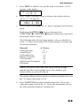
5.
Here is where you change the “n” factor to prompt Yule-Nielson
mode.
Hold down the ZERO (ts) button, then press the
FUNCTION (t) or ENTER (s)button to adjust the value until
the desired value is shown.
The following table lists the approximate value you should set
as the “n” factor when using Yule-Nielson mode to measure ink
on various materials:
Material
“n” Factor
Uncoated Paper
2.7
Coated Paper
1.6-1.7
3M Transfer Key
1.9
DuPont Cromalin
2.6
3M Color Key
4.0
Agfa-Gevaert Gevaproof 1.4
Newsprint
2.5
TIP: If you need to move the value up or down by a large
amount, hold the arrow buttons down. The numbers will
advance faster as you hold it down.
To return to Murray-Davies mode, use these procedures to re-set
the “n” factor value back to 1.00.
6.
Press FUNCTION to return to normal operation. If you set a
value other than 1.00 for the “n” factor, the instrument will use
the Yule-Nielson formula to calculate dot.
4-3
400 B/W Reflection Densitometer
SELECTING DOT AREA OR DOT GAIN
1.
If this is your first time selecting a measurement function, you
should plug your instrument in using its AC adapter. This will
prevent the microprocessor from going into “sleep” mode to
save battery power. With the instrument plugged in, you’ll be
free to take your time learning this procedure.
2.
Next, make sure you have the desired response setting selected,
and that the instrument is properly calibrated. These procedures
are covered in the previous chapter, “Calibration.”
3.
To select the measurement method for measuring ink density,
press the FUNCTION button repeatedly until DOT AREA or
DOT GAIN appears in the display (each time you press the
button the display toggles between DEN and DOT AREA or
DOT GAIN).
DOT AREA
4.
4-4
DOT GAIN
If DOT AREA appears and you wish to select DOT GAIN, press
and release the ZERO button to toggle the selection. Do the
same if DOT GAIN appears and you wish to select DOT AREA.
Dot Functions
DOT AREA FUNCTION
Once dot area measurement (DOT AREA) mode is selected, PAPER
appears in the display.
PAPER
1.
Center the instrument target window over a sample of the paper,
then lower the instrument head to take a reading and hold.
If the instrument recognizes the measurement as a paper
reading, the display flashes DOT B (or DOT R) momentarily,
then becomes ready for the first SOLID reading.
If the instrument does not recognize the measurement as a
paper reading, PAPER? Z appears.
PAPER? Z
Keep the instrument pressed down, then press ZERO to
indicate that yes, this is the new paper value. Then, the display
becomes ready for the first SOLID reading.
SOLID
2.
Measure the solid patch. DOT is displayed during measurement,
then the measurement data appears.
DOT
1.57s
If Solid is displayed as a Dot value (a percentage, such as 94%)
instead of a solid density value (such as 1.57s), hold the
instrument closed and press ZERO.
If SOLID? Z is displayed, press ZERO to measure as a Solid,
then release the instrument.
NOTE: Solid density is displayed minus paper.
4-5
400 B/W Reflection Densitometer
3.
Read a tint of the solid color you just measured. During
measurement, DOT is displayed. Then, the Dot value is
displayed.
DOT
75 %
4.
Measure additional tints of that color. The instrument
automatically recognizes the measurements as tint values and
displays the tint percentage.
5.
When you are ready to measure another color, simply measure
the solid and repeat the procedures beginning with #2. The
instrument automatically recognizes the measurement as a
solid. Also, you do not need to enter a new paper measurement.
Display Messages
If any display messages that have not been covered in this chapter
appear during any of the dot gain functions, see “Miscellaneous
Display Messages” at the end of Chapter 3 for an explanation and
instructions.
4-6
Dot Functions
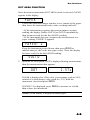
DOT GAIN FUNCTION
Dot gain measurement compares the tint percentage of a color patch
on paper to the intended tint percentage produced on the film.
Your first dot gain measurement compares the dot percentage of the
measured patch to the first reference value (r1). The difference
between the reference value and the measured value is calculated as
dot gain the amount the ink dots have spread on the paper.
If needed, you can adjust the Reference values to meet your specific
needs. These procedures are covered next. If you wish to simply use
the factory preset reference values, you can skip ahead to “Dot Gain
Measurement.”
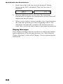
Adjusting Dot Gain Reference Values
Once dot gain measurement (DOT GAIN) mode is selected, PAPER
appears in the display.
PAPER
1.
Press ZERO. REF appears in the display momentarily, followed
by one of the reference valueseither r1, r2, or r3.
<
2.
75 {
When the color and reference value you wish to change appear
in the display, use ZERO (ts), ENTER (s), and
FUNCTION (t) buttons to adjust the value.
Press and hold ZERO, then press ENTER (s) to raise the
value;
Press and hold ZERO, then press FUNCTION (t) to lower
the value.
When you change the preset values, they are turned “off.” Your
new reference values can be set within the following ranges.
r1 can be set between 1% and 45%.
—r2 can be set between 46% and 64%
r3 can be set between 65% and 100%
These value ranges apply to both optics.
3.
Advance to the next reference value, then repeat #2; or press
ZERO to advance to the next reference value, either r1, r2, or r3.
4-7
400 B/W Reflection Densitometer
4.
Repeat #2 and #3 until all reference values are set to your
preferences.
5.
Press FUNCTION to return to dot gain measurement mode.
Measurements at each tint will be compared to the appropriate
reference value.
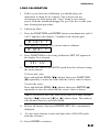
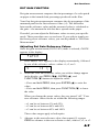
Dot Gain Measurement
Once dot gain measurement (DOT GAIN) mode is selected, PAPER
appears in the display.
PAPER
1.
Center the instrument target window over a sample of the paper,
then lower the instrument head to take a reading and hold.
If the instrument recognizes the measurement as a paper
reading, the display flashes DOT B (or DOT R) momentarily,
the paper value is displayed, then becomes ready for the first
SOLID reading.
If the instrument does not recognize the measurement as a
paper reading, PAPER? Z appears.
PAPER? Z
Keep the instrument pressed down, then press ZERO to
indicate that yes, this is the new paper value. Then, the display
becomes ready for the first SOLID reading.
SOLID
2.
Measure the solid patch. DOT is displayed during measurement,
then the measurement data appears.
If Solid is displayed as a Dot value (a percentage, such as 94%)
instead of a solid density value (such as 1.57s), hold the
instrument closed and press ZERO.
DOT
1.57s
If SOLID? Z is displayed, press ZERO to measure as a Solid,
then release the instrument.
NOTE: Solid density is displayed minus paper.
4-8
Dot Functions
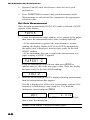
3.
Read the first tint of the solid color you just measured. This
should be the color patch with the lowest tint percentage, such
as the 25% patch. During measurement, DOT X is displayed.
Then, the Dot Gain value is displayed.
st
Mark indicates 1 tint measured
25' %
DOT X
A mark before the percentage symbol indicates which tint
percentage in the sequence has been measured.
nd
2 dot gain measurement
3rd measurement
50'' %
4.
75''' %
Measure the remaining tints of that color. The instrument
automatically recognizes the measurements as tint values and
displays the dot gain value for that tint. Display marks indicate
which tint percentage in the sequence has been measured.
Display Messages
If any display messages that have not been covered in this chapter
appear during any of the dot gain functions, see “Miscellaneous
Display Messages” at the end of Chapter 3 for an explanation and
instructions.
4-9
400 B/W Reflection Densitometer
4-10
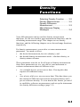
5
Range
Functions
Reference Value ...................... 5-1
Absolute Range Measurement.. 5-2
Range Minus Reference
Measurement ..................... 5-2
The Range function subtracts the lowest measurement from the
highest and displays the difference.
Range = Dmax – Dmin
where Dmax = Maximum (highest) density
and Dmin = Minimum (lowest) density
The Range function can have a reference value (if selected)
subtracted form the measurement, giving you a difference value.
Before the Range can be calculated, a reference value needs to be
selected. You can display a previous value or enter a new step
reference. Absolute Range takes a true reading of the sample—
including the paper or reference. Range Minus Reference takes into
account the effect of the paper or reference and calculates only the
ink density.
DISPLAY/ENTER A REFERENCE VALUE
There are two ways to display the reference value: at menu level or
when data is displayed after entering a –REF function. To enter a
reference value, a Step Reference must be performed.
To display the reference value:
Ÿ
At menu level (e.g. when RANGE –R is displayed) hold ZERO
depressed until the reference value appears.
Ÿ
Once the reference value is displayed, Reference can be entered
by numerically entering the reference value using the ZERO
5-1
400 B/W Reflection Densitometer
key in conjunction with FUNCTION (to decrease the value) or
ENTER (to increase). After entering the reference value, or if
you want to exit the reference function at anytime, momentarily
press FUNCTION and the display will return to normal
operation.
To enter a reference value:
Ÿ
Press FUNCTION to select RANGE –R. If RANGE appears,
press ZERO to turn Reference on. READ NEW is displayed.
With unit up, depress and hold ZERO until REF is
momentarily displayed. The reference is then displayed. A new
reference can be entered by using the arrow keys. After
reference entry, press FUNCTION to return to normal
operation.
ABSOLUTE RANGE MEASUREMENT
1.
Press FUNCTION to select RANGE. If RANGE –R appears,
press ZERO to turn Reference off. READ NEW is displayed.
2.
Measure the patch. RANGE X is displayed while measuring,
where X is the installed optics. When the read head is down,
current density value is displayed. In addition, a ∧,∨, or D is
displayed to indicate Dmax, Dmin, or a density within range,
respectively.
3.
When the read head is released the range is displayed.
NOTE: Momentary depressions of the ZERO key pages through the
minimum value, maximum value, READ NEW, and the range
value.
5-2
Range Functions
RANGE MINUS REFERENCE MEASUREMENT
1.
Press Function to select RANGE –R. If RANGE appears, press
ZERO to turn Reference on. READ NEW is displayed.
2.
Measure Patch. RANGE X is displayed while measuring,
where X is the installed optics. When the read head is down,
current density value is displayed. In addition, a ∧,∨, or D is
displayed to indicate Dmax, Dmin, or a density within range,
respectively.
3.
When the read head is released, the range value minus the
reference is displayed.
NOTE: Momentary depressions of the ZERO key will page through
the minimum value, maximum value, READ NEW, and the range
value.
5-3
400 B/W Reflection Densitometer
5-4
6
Technical
Information
Serial Interface Information ...... 6-1
Instrument Specifications.......... 6-4
Accessories .............................. 6-6
General Cleaning...................... 6-7
Optics Maintenance .................. 6-7
Target Window Replacement.... 6-8
Lamp Replacement .................. 6-9
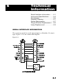
SERIAL INTERFACE INFORMATION
The connector used for serial input/output is a Modular 10 circuit
type. Figure 5-1 is the connection diagram.
Figure 5-1
6-1
400 B/W Reflection Densitometer
An RS232 to modular interface adapter is available from X-Rite
which performs as shown in the diagram on the previous page. This
adapter also provides a jack for the AC adapter so that only one
cable need be connected to the 400. Also, when the adapter is not
connected to the jack, the +V CHARGER is connected to pin 9 of
the DB25 in the diagram. The charger ground is connected to the
jack ground only.
The part numbers for these interface adapters are: P/N 418-70 (male
DB25 connector) P/N 418-71 (female DB25 connector) See
“Accessories” later in this chapter for other adapters.
A 10-foot modular to modular cable for connection of the 400 to the
interface adapter is available by ordering P/N SE108-69.
Term Definitions
Pin 2 Transmitted Data: Data transmitted from the densitometer
with parameters (baud rate, format) set by the densitometer.
Pin 3 Received Data: Data received by the densitometer from
outside source using the same parameters as the densitometer.
Pin 4 DTR (Data Terminal Ready): Logic 0 active (On Line) and
Logic 1 during: Power Off, Power Up, Self Test, during
measurements, and when serving RCI.
Pin 5 is ignored.
Pin 7: This pin is used for supplying 12VDC @ 700ma for charging
the 400 without having the Adapter connected directly to the unit.
Input Characteristics
Logic 1=+.8VDC to -25VDC
Logic 0=+2.25VDC to +25VDC
Output Characteristics
Logic 1=approximately -4VDC
Logic 0 = approximately +5VDC
Outputs are @ 0VDC during Power Down.
6-2
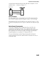
Technical Information
A typical interconnection between the 400 and a computerin its
simplest form is shown in Figure 5-2.
Figure 5-2
Serial Output
The data format that is transmitted from the 400 is determined by
the I/O PORT options found in Chapter 1 under “I/O Port Setup.”
Data transmitted by the 400 shall have one start bit (Logic 0), 7 bits
of ASCII, one parity bit (set to Logic 0), and then one stop bit (Logic
1).
Serial Input Commands
Your 400 is equipped with an input that allows the 400 to be
controlled or monitored remotely. Every function that can be
performed by the 400 (plus a few special functions not activated by
the keyboard) can be activated via the serial input. This Remote
Control Interface is covered by U.S. Patent 4,591,978.
For more information on Serial Input Commands and remote
control operation of the 400, contact X-Rite Customer Services at
1-888-826-3059.
6-3
400 B/W Reflection Densitometer
INSTRUMENT SPECIFICATIONS
Display
Dot Matrix LCD
Measuring Geometry
ANSI PH 2.17/DIN 16536 multi-sensor array
Light Source
Filament bulb 3000ºK DIN approx. 2856ºK ANSI
Receiver
Silicon Photodiode
Color Response
B optics with X-Rite Orthochromatic Response.
R optics with X-Rite Red (Laser) Response.
Measuring Range
0.00D-2.5D for B & R
0.00D-2.20D for BS & RS
0-100% dot
Reproducibility
±0.01D
±1% for dot area (10-100%)
Linearity
±0.01D or ±1%
Inter-Instrument Agreement
±0.02D or ±2%
Aperture Diameter
400B,R3.4mm
400BS,RS1.7mm
Calibration
Automatic with Quick Cal™
Adjusts Zero and Slope for Density
Warm Up Time
None
6-4
Technical Information
Zero Stability
±.01D maximum per 8 hours
Slope Stability
±1% maximum per year
Power Supply
Six rechargeable AA NI-CAD batteries 7.2v total rated @600m Ah
(included)
Charge Time
Approximately 14 hours
AC Adapter Requirements
400 90-130VAC, 50-60Hz, 15W Maximum
400X 180-260VAC, 50-60Hz, 15W Maximum
Operating Temperature Range
50º-104ºF /10º-40ºC
Measurements Per Charge
Approx. 4500 (usage dependent)
Measuring Time
Approximately 0.5 seconds
Weight
800 grams
Dimensions
7.4cm H x 8.cm W x 19.6cm L
6-5
400 B/W Reflection Densitometer
ACCESSORIES
Accessories Included
Reflection Reference
Operation Manual
AC Adapter
Carrying Case
Specifications and design subject to change without notice.
Accessories and Replacement Parts Available
Security Cable .............................................................. P/N 418-75
1.7mm Target Window...................................P/N 418-21-017-KIT
3.4mm Target Window...................................P/N 418-21-034-KIT
1.7mm Aperture .................................................... P/N 418-63-017
3.4mm Aperture .................................................... P/N 418-63-034
Lamp Assembly............................................................ P/N 418-13
B Optics ..................................................................... P/N 400B-35
BS Optics ................................................................. P/N 400BS-35
R Optics ..................................................................... P/N 400R-35
RS Optics ................................................................. P/N 400RS-35
Modular Interconnect Cable...................................... P/N SE108-69
DB25P DCE (Null Modem) Interface Adapter .............. P/N 418-70
DB25S DCE (Null Modem) Interface Adapter .............. P/N 418-71
DB25P DTE (Normal) Interface Adapter ..................... P/N 418-80
DB25S DTE (Normal) Interface Adapter ...................... P/N 418-81
DB9P Interface Adapter................................................ P/N 418-90
DB9S Interface Adapter................................................ P/N 418-91
Modular Interconnect Cable for Macintosh® computers
with 8 pin mini-DIN connector..................................... P/N 418-79
For further information on accessories contact your X-Rite
representative or call X-Rite, Inc. at: 1-888-826-3059.
6-6
Technical Information
GENERAL CLEANING
The exterior of the instrument can be wiped clean with a cloth
dampened in water or a mild cleaner whenever required.
NOTE: Do not use any solvents to remove ink from the cover.
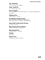
OPTICS MAINTENANCE
1.
Remove Optics assembly by removing sensor nose screws from
densitometer housing, and then lifting the assembly upward.
(Figure 5-3)
Figure 5-3
5
4
3
2
1
2.
Remove three inner screws [1] on sensor nose [2] and rotate
Optics over carefully so sensor nose [2] is at bottom.
3.
Carefully lift up Optics assembly [4] separating from sensor
nose [2].
4.
Clean Optics sensors with camelhair brush and set aside.
5.
Carefully remove IR Glass [3] and optional polarizing filter (if
installed) from sensor nose [2].
6.
Remove dust and lint from inner sensor nose and filter(s) with
camelhair brush.
6-7
400 B/W Reflection Densitometer
7.
Carefully reinstall optional polarizing filter (if used) and IR
Glass [3] (holding both by edges) into sensor nose, making sure
filter(s) are properly seated.
8.
Align flat edge of sensor nose [2] with flat edge on Lamp
assembly P.C.B [5] and secure sensor nose [2] to Optics
assembly [4] with three inner screws [1].
9.
Carefully reinstall Optics assembly into densitometer by facing
flat edge of sensor nose to front of densitometer. Work into
position until alignment pins and connector pins are properly
seated.
10. Insert and tighten sensor nose screws.
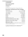
TARGET WINDOW REPLACEMENT
1.
Remove old target window by pushing downward on top of shoe
[1]. Clean off any remaining adhesive from shoe. (Figure 5-4)
Figure 5-4
4
2
1
3
6-8
2.
Turn densitometer over and compress shoe [1] all the way
down, and lock shoe.
3.
Remove paper backing from tape strip on new target window
[2].
Technical Information
4.
Place one taped edge of target window [2] on indent [4] at
bottom of shoe [1].
5.
Align hole of target window [2] exactly in center of hole in
sensor nose [3] and press remaining three sides of target
window into place.
6.
Unlock shoe.
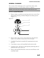
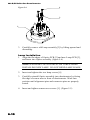
LAMP REPLACEMENT
Lamp Removal
1. Remove Optics assembly by removing sensor nose screws [1]
from the densitometer housing, and then lifting assembly
upward. THE THREE INNER SCREWS ON SENSOR NOSE
ARE NOT TO BE REMOVED. (Figure 5-5)
Figure 5-5
1
Densitometer
Housing
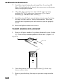
2.
Once Optics assembly is free, rotate over and remove two
screws [4] from the lamp PCB [3]. (Figure 5-6)
6-9
400 B/W Reflection Densitometer
Figure 5-6
4
3
2
3.
Carefully remove old Lamp assembly [3] by lifting upward and
discarding.
Lamp Installation
1. Align the flat edges of Optics PCB [2] and new Lamp PCB [3],
and insert into Optics assembly. (figure 5-6)
NOTE: EXTREME CAUTION MUST BE TAKEN WHEN
INSTALLING NEW LAMP. DO NOT BEND LAMP LEADS.
6-10
2.
Insert and tighten the two lamp screws [4].
3.
Carefully reinstall Optics assembly into densitometer by facing
flat edge of sensor nose to front of densitometer. Work into
position until alignment pins and connector pins are properly
seated.
4.
Insert and tighten sensor nose screws [1]. (Figure 5-5)
7
Appendix
and Index
Proprietary Notice....................... 7-1
Limited Warranty........................ 7-2
Index .......................................... 7-3
PROPRIETARY NOTICE
The information contained in this manual is derived from patent and
proprietary data from X-Rite, Incorporated. This manual has been
prepared solely for the purpose of assisting operation and
maintenance personnel in their use and general maintenance of the
X-Rite 400.
The contents of this manual are the property of X-Rite, Incorporated
and are copyrighted. Any reproduction in whole or part is strictly
prohibited. Publication of this information does not imply any rights
to reproduce or use it for purposes other than installing, operating, or
maintaining the equipment described herein.
This instrument is covered by one or more of the following U.S.
patents: #4,080,075; #4,591,978; #5,015,098; and patents pending.
Foreign patent numbers provided on request.
7-1
400 B/W Reflection Densitometer
LIMITED WARRANTY
X-Rite, Incorporated warrants each instrument manufactured by
them to be free of defects in material and workmanship for a period
of 12 months. THERE ARE NO WARRANTIES OF
MERCHANTABILITY OR FITNESS. THIS WARRANTY
OBLIGATION IS LIMITED TO SERVICING THE UNIT
RETURNED TO THE FACTORY FOR THAT PURPOSE AND
EXCLUDES THE LAMP AND NI-CAD BATTERIES.
The instrument shall be returned with transportation charges
prepaid. If the fault has been caused by misuse or abnormal
operating conditions, repairs will be billed at a nominal cost. In this
case, an estimate will be submitted before work is started, if
requested.
A Warranty Registration Card is enclosed with each instrument.
The purchaser should fill in the card completely and return it to XRite, Incorporated postmarked no later than ten (10) days from the
date of receipt. This card registers your system with us for warranty
coverage. Once your unit is registered, we are able to maintain a file
to help expedite service in case it is needed.
Always include serial number and place of purchase in any
correspondence concerning your instrument. The serial number is
located at the rear of the instrument.
X-Rite, Incorporated offers a repair program for instruments out of
warranty. For more information, contact X-Rite Technical Services
Department.
This agreement shall be interpreted in accordance with the laws of
the State of Michigan and jurisdiction and venue shall lie with the
courts of Michigan as selected by X-Rite, Incorporated.
7-2
Index
Absolute Range Measurement, 5-2
Maintenance, 6-7
Accessories, 6-6
Murray-Davies formula, 4-2
Adjusting the display angle, 1-9
Batteries and Power, 1-6, 1-7
Calibration, 2-2
Long Calibration, 2-3
Quick Cal, 2-4
Charging the battery, 1-6
Packaging and Parts, 1-3
PAPER, 3-4
Powering the Instrument, 1-6
Quick Cal™, 2-4
Range Minus Reference
Measurement, 5-2
Cleaning, 6-7
Reference / Paper value, 5-1, 5-2
Density functions, 3-1, 3-2
Response settings, 2-1
Density difference measurement,
3-3
Responses, 2-2
Return Packaging, 1-3
Density measurement, 3-2
RS232 connector interface, 1-12
Display messages, 3-4
Dot functions, 4-1, 4-4
Dot area function, 4-5
Dot gain function, 4-7
Features, 1-1
I/O port setup, 1-10
Selecting response, 2-14
Serial interface information, 6-1
Specifications, 6-4
Unlocking/Locking the Shoe, 1-5
Yule-Nielson formula, 4-2
Instrument Vocabulary drawings,
1-4
7-3
400 B/W Reflection Densitometer
7-4
X--Rite, Incorporated—World Headquarters
3100 44th Street S.W. • Grandville, Michigan 49418 • USA
www.x-rite.com • (616) 534-7663
Toll-Free U.S. Numbers
Tel: 1-888-826-3059 • Fax: 1-888-826-3061
Toll-Free International Numbers
Tel: 1-888-826-3039 • Fax: 1-888-826-3041
X-Rite GmbH
Stollwerckstraße 32 • 51149 Köln • Germany
Tel: (49) 2203-91450 • Fax: (49) 2203-914519
X-Rite GmbH
Sochorova 705 • CZ-682 • 11 Vyskov • Czech Republic
Tel: (420) 507-328197 • Fax: (420) 507-328138
X-Rite Asia Pacific Ltd.
Room 808-10 • Kornhill Metro Tower • 1 Kornhill Road • Quarry Bay
Hong Kong • Tel: (852) 2-568-6283 • Fax: (852) 2-885-8610
X-Rite Ltd.
The Acumen Centre • First Avenue
Poynton, Cheshire • England
Tel: 44-0-1625-871100 • Fax: 44-0-1625-871444
X-Rite Méditerranée
Parc du Moulin de Massy • 35, rue du Saule Trapu • 91300 Massy • France
Tel: 33-1-69.53.66.20 • Fax: 33-1-69.53.00.52
X-Rite Asia Pacific Ltd. - Japan Office
Suite 506 AIOS Gotanda • 1-7-11 Higashi-Gotanda
Shinagawa-ku, Tokyo • 141-0022 Japan
Tel: 81-3-5447-1607 • Fax: 81-3-5447-1608
P/N 400-500 Revision X-01/28/00