1
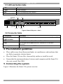
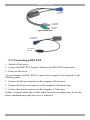
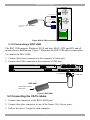
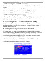
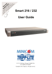
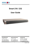
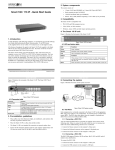
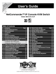
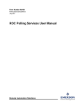
1111 W. 35th Street, Chicago, IL 60609 USA www.tripplite.com/support Copyright ©2012 Tripp Lite. All rights reserved. Smart 216 / 232 – Quick Start Guide 1. Introduction To take advantage of the Smart 216 / 232 full range of features, we recommend you read the softcopy User Guide after performing the Quick Start procedure. It’s in PDF format on the supplied CD or on our website www.minicom.com in the Support section. All references throughout this guide to the Smart 216 refer equally to the Smart 232. The two units are functionally the same. The Smart 216 has 16 Server ports and the Smart 232 has 32 Server ports. The Smart 216 extends your KVM (keyboard, video, and mouse) from servers with PS/2 or USB interfaces up to 30m/100ft away. 2 users can control, monitor and manage up to 16 servers simultaneously. You can connect a Power Distribution Unit (PDU) for power management. 2. System components The system consists of: 1 Smart 216 (p/n 1SU22090) or 1 Smart 232 (p/n 1SU22091) Rack mounting set (p/n 5AC20247) ROCs - PS/2, USB 3. The Smart 216 unit Figure 1 illustrates the front panel of the Smart 216. SMART 216 A MINICOM 1 Power Link 2 Remote Figure 1 Smart 216 ports – side 1 SMART 216 / 232 3.1 LED and button table LED Function Power Link Remote 1 and 2 Power Indicator Unit is connected to the network Illuminates when the respective user connects to a server Remote Power Switch (RPS) port Monitor Monitor USER 2 USER 1 RPS I 0 1 LAN POWER 100-240 VAC 50/60 Hz LAN (Ethernet) port Power Mouse Keyboard 2 3 4 Mouse 5 6 7 8 9 SERVER 10 11 12 13 14 15 16 Server ports Keyboard Figure 2 Smart 216 ports – side 2 3.2 Connector table Connector Function User 1 and User 2 KVM consoles RPS LAN Connect 2 KVM consoles for two users to operate the Smart 216 Server ports Connect Minicom’s Serial Remote Power Switch To configure and update the unit, connect to 10/100 Mbit Ethernet. Connect to servers via ROCs 4. Pre-installation guidelines Place cables away from fluorescent lights, air conditioners, and machines that are likely to generate electrical noise Place the Smart 216 on a flat, clean and dry surface or install in a rack Ensure that the maximum distance between each computer and the Smart 216, does not exceed 30m/100ft. 5. Connecting the system Figure 3 illustrates the Smart 216 system overview. 1 QUICK START GUIDE User 1 User 2 Keyboard, monitor and mouse connected to KVM User 2 ports Keyboard, monitor and mouse connected to KVM User 1 ports RPS I 0 POWER 100-240 VAC 50/60 Hz USER 2 LAN USER 1 1 2 3 4 5 6 7 8 9 SERVER 10 11 12 13 14 15 16 PDU connected to RPS port To servers ROCs PDU Figure 3 Smart 216 system overview 5.1 The ROCs Each computer/ server is directly connected to the Smart 216 via the appropriate RoC using CAT5 cable in a star configuration. No external power is needed at the ROCs. The ROCs draw their power from the computer’s keyboard port (ROC PS/2) or from the USB port (ROC USB). The figures below illustrate the ROC PS/2 and ROC USB. 2 SMART 216 / 232 To computer’s Video card To computer’s keyboard port To computer’s mouse port Figure 4 ROC PS/2 To computer’s Video Card To computer’s USB Port Figure 5 ROC USB 5.1.1 Connecting a ROC PS/2 1. Switch off the server. 2. Connect the ROC PS/2. Figure 6 illustrates the ROC PS/2 connections. 3. Power on the server. You can connect the ROC PS/2 to a powered on computer, but it must be in the following order: 1. Connect the Mouse connector to the computer’s Mouse port. 2. Connect the Keyboard connector to the computer’s Keyboard port. 3. Connect the Screen connector to the computer’s Video port. Failure to connect in the above order while the server is running, may lead to the mouse malfunctioning until the server is rebooted. 3 QUICK START GUIDE To Keyboard port Mouse Keybd 100T To Mouse port Parallel Serial A Video ROC PS/2 Serial B CAT5 cable to switch Server port To Video port SCSI PCI 33Mx32b PCI 33Mx32b PCI 33Mx32b PCI 33Mx32b Figure 6 ROC PS/2 connections 5.1.2 Connecting a ROC USB The ROC USB supports Windows 98 SE and later, MAC, SUN and SGI, and all modern Linux distributions. Figure 7 illustrates the ROC USB and its connections. To connect the ROC USB: 1. Connect the Screen connector to the computer’s Video port. 2. Connect the USB connector to the computer’s USB port. To Video port ROC USB CAT5 cable to switch Server port Figure 7 ROC USB 5.2 Connecting the CAT5 cables 1. Connect one connector to the ROCs RJ45 port. 2. Connect the other connector to one of the Smart 216’s Server ports. 3. Follow the above 2 steps for each computer. 4 To USB port SMART 216 / 232 5.3 Connecting the two KVM consoles Connect a keyboard, monitor and mouse to each of the User 1 and User 2 ports as follows: 1. Connect the monitor connectors to the Monitor ports. 2. Connect the USB keyboard connectors to the USB Keyboard ports. 3. Connect the USB mouse connectors to the USB Mouse ports. 5.4 Connecting to the power supply 1. Using the Power cord provided, connect the Smart 216 to a socket outlet with grounding connection. Only use the power cord supplied with the unit. 2. Switch on the Smart 216. 6. Connecting to the Local Area Network (LAN) Configuration is done mainly via a web interface. For this purpose connect a network cable to the LAN port of the Smart 216. This must be done before powering on the Smart 216. 7. Setting network parameters via the OSD By default, Smart 216 boots with an automatically assigned IP address from a DHCP (Dynamic Host Configuration Protocol) server on the network. The DHCP server provides a valid IP address, gateway address and subnet mask. You can identify the IP address from the OSD. Also where there is no DHCP server set the IP address via the OSD as follows: 1. From the local keyboard, press left Shift twice. The OSD Main window appears. 2. Press F2. The Settings window appears see Figure 8. Figure 8 Settings window 5 QUICK START GUIDE In the Settings window you navigate downwards using the Tab key. At the bottom of the window, press tab to go to the top of the window. Change settings by typing in the selected area or by pressing the spacebar – whichever is relevant. 8. Logging into the web configuration 1. Open your web browser. 2. Type the Smart 216 system IP address – http or https://IP address/ - and press Enter. The login page appears. 3. Type the default Administrator user name - admin - and password - access (both lower case). 4. Press Enter. The web interface opens at the Targets page. See Figure 9. Figure 9 Targets page Columns: Server name - The server name can be changed in the configuration settings to give the server an identifiable name. Server Status - Server Status can be on, off or busy (i.e. a user is accessing the server). User – The current user (if any) accessing the server. From the Targets page menu - see Figure 9 - an Administrator can: Change the password Reach the configuration pages See an event log 6 SMART 216 / 232 9. Operating the system via the OSD To display the OSD: 1. From the local keyboard, press the left Shift key twice. The OSD Main window appears. See Figure 10. Server status: Off Port number appears here Server status: On Instruction keys Figure 10 OSD Main window 9.1 Navigating the OSD Main window To navigate up and down use the Up and Down arrow keys. To exit the OSD press Esc. 9.2 Selecting a computer To select a computer: 1. Navigate to the desired computer line. Or, type the two-digit port number of the desired computer. 2. Press Enter. The selected computer is accessed. A Confirmation label appears showing which computer is accessed. For the full configuration and operation instructions see the full softcopy User Guide on our website: http://www.minicom.com/supportuserguides.htm 7 201204201 • 933196_EN