1
1
User’s Manual for the
Boundary Devices
Neon board
R
December 28, 2005
December 28, 2005
Revision 2.8
2
1
Revision History
Date
2005-03-20
2005-04-03
2005-06-11
2005-06-27
2005-07-23
2005-08-09
2005-09-15
2005-10-21
2005-11-07
2005-11-09
Revision
1.0
1.3
2.0
2.1
2.2
2.3
2.4
2.5
2.6
2.7
2005-12-28
2.8
December 28, 2005
Description
First draft
Added minidebug instructions
Added display config, networking notes
Added connector pin-outs (Figure 2)
Updated U-Boot version
Added notes on mac address command
Bumped BSP revision
Bumped U-Boot revision
Added userland build notes
Added rootfs usage notes and list of supported libraries
Minor updates regarding sshd and userland libraries.
Revision 2.8
CONTENTS
3
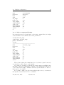
Contents
1 Revision History
2
2 Intended Audience
5
3 Overview of features
5
4 Hardware feature
4.1 Layout . . . . . . . . . .
4.2 Mounting . . . . . . . .
4.3 Connector reference . .
4.4 Electrical characteristics
5
5
6
6
8
.
.
.
.
.
.
.
.
.
.
.
.
.
.
.
.
.
.
.
.
.
.
.
.
.
.
.
.
.
.
.
.
.
.
.
.
.
.
.
.
.
.
.
.
.
.
.
.
.
.
.
.
.
.
.
.
.
.
.
.
.
.
.
.
.
.
.
.
.
.
.
.
.
.
.
.
.
.
.
.
.
.
.
.
5 Software features
5.1 Das U-Boot . . . . . . . . . . . . . . . . . . . . . . . . . . . .
5.1.1 Requirements for building under Linux . . . . . . . . .
5.1.2 Requirements for building under Windows with Cygwin
5.1.3 General build steps . . . . . . . . . . . . . . . . . . . .
5.1.4 Tailoring U-Boot for your application . . . . . . . . .
5.1.5 U-Boot Memory layout . . . . . . . . . . . . . . . . .
5.1.6 U-Boot Init Script . . . . . . . . . . . . . . . . . . . .
5.2 Windows CE . . . . . . . . . . . . . . . . . . . . . . . . . . .
5.2.1 Prerequisites and components . . . . . . . . . . . . . .
5.2.2 BSP Installation . . . . . . . . . . . . . . . . . . . . .
5.2.3 Building the demo . . . . . . . . . . . . . . . . . . . .
5.3 Linux Support . . . . . . . . . . . . . . . . . . . . . . . . . .
5.3.1 Crosstool Linux Toolchain . . . . . . . . . . . . . . . .
5.3.2 Crosstool Embedded (Das U-Boot) Toolchain . . . . .
5.3.3 GNUARM binaries . . . . . . . . . . . . . . . . . . . .
5.3.4 Kernel 2.4.19 . . . . . . . . . . . . . . . . . . . . . . .
5.3.5 Kernel 2.6 . . . . . . . . . . . . . . . . . . . . . . . . .
5.3.6 Userland build tool . . . . . . . . . . . . . . . . . . . .
5.3.7 Userland libraries and applications . . . . . . . . . . .
5.3.8 Notes about userland root filesystems . . . . . . . . .
5.3.9 mmcinitrd.u-boot . . . . . . . . . . . . . . . . . . . . .
5.3.10 Javascript stuff . . . . . . . . . . . . . . . . . . . . . .
5.3.11 Login and SSHD support . . . . . . . . . . . . . . . .
9
9
9
9
10
10
12
13
14
14
14
15
16
16
17
18
19
19
20
22
23
25
25
25
6 Development Tools
6.1 minidebug . . . . . . . . . . .
6.1.1 mdebug . . . . . . . .
6.2 JTAG system-level debugger
6.2.1 Requirements . . . . .
6.2.2 Startup Options . . .
26
26
27
27
28
28
December 28, 2005
.
.
.
.
.
.
.
.
.
.
.
.
.
.
.
Revision 2.8
.
.
.
.
.
.
.
.
.
.
.
.
.
.
.
.
.
.
.
.
.
.
.
.
.
.
.
.
.
.
.
.
.
.
.
.
.
.
.
.
.
.
.
.
.
.
.
.
.
.
.
.
.
.
.
.
.
.
.
.
.
.
.
.
.
.
.
.
.
.
.
.
.
.
.
CONTENTS
4
.
.
.
.
.
.
.
.
.
.
.
.
.
.
.
.
.
.
.
.
.
.
.
.
.
.
.
.
.
.
.
.
.
.
.
.
.
.
.
.
.
.
.
.
.
.
.
.
.
.
.
.
.
.
.
.
.
.
.
.
30
30
30
32
33
7 Configuration Notes
7.1 Display configuration . . . . . . . . . . . .
7.1.1 What display is currently selected?
7.1.2 What displays are supported...? . .
7.1.3 Select a supported display . . . . .
7.1.4 Define and test a new display . . .
7.1.5 Saving settings to Flash EEPROM
7.2 Memory size configuration . . . . . . . . .
7.3 Upgrading U-Boot . . . . . . . . . . . . .
7.4 Touch Panel Calibration . . . . . . . . . .
7.5 Ethernet MAC Addresses . . . . . . . . .
.
.
.
.
.
.
.
.
.
.
.
.
.
.
.
.
.
.
.
.
.
.
.
.
.
.
.
.
.
.
.
.
.
.
.
.
.
.
.
.
.
.
.
.
.
.
.
.
.
.
.
.
.
.
.
.
.
.
.
.
.
.
.
.
.
.
.
.
.
.
.
.
.
.
.
.
.
.
.
.
.
.
.
.
.
.
.
.
.
.
.
.
.
.
.
.
.
.
.
.
.
.
.
.
.
.
.
.
.
.
34
34
35
36
38
39
40
40
41
42
43
6.3
6.4
6.2.3 Control Keys . . . . . . . . . .
6.2.4 Blast protocol . . . . . . . . . .
6.2.5 Quick-start download and burn
TeraTerm blast extensions . . . . . . .
Using U-Boot Networking . . . . . . .
December 28, 2005
Revision 2.8
.
.
.
.
.
5
2
Intended Audience
This document aims to provide the information needed to integrate the
R
Neon
board into your application. As such, it addresses both hardware
and software integration.
3
Overview of features
R
The following are highlights of the Neon
board.
• Available with Windows Ce or Linux Operating Systems
• Full featured Boot Loader for custom startup
• 400 MHz Intel PXA-255 CPU
• 32 or 64MB SDRAM
• 8 or 32MB Intel StrataFlash (tm) EEPROM
• Silicon Motion SM 501 Graphics Controller
• Active Matrix LCD Support,
• Including Full-Motion Video
• STN Passive LCD Display Support
• 4 or 5-Wire Resistive Touch-Screen Support
• 44KHz Stereo 16-Bit Audio Output, for Headphones or Speakers
• 44KHz Monaural Audio Input (microphone)
• 1 RS-232 or TTL Serial Port
• 1 USB 1.1 Slave Port
• 1 USB 1.1 Master Port
• Built-in 10/100 Ethernet Controller,
• Built-in Interface for Magnetic Stripe Readers and Printers
• MMC Slot for Expanded Storage
• General Purpose I/O for Device Control
• Built-in Switching Power Supply for 5V DC Input
• JTAG Interface
• Customized Versions Available
4
4.1
Hardware feature
Layout
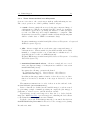
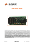
R
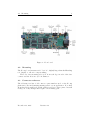
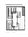
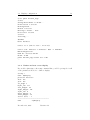
As shown in Figure 1, the Neon
board contains a wide variety of I/O
options for use in your application. Note that some of these may not be
populated on an evaluation or production board.
December 28, 2005
Revision 2.8
4.2
Mounting
6
Figure 1: Neon board
4.2
Mounting
R board measures 2.75” by 6.75”, slightly larger than the Hitachi
R
The Neon
6.2” display, to allow for easy mounting.
There are four mounting holes 1/4” from each edge in each of the four
corners, and the holes are 1/8” in diameter.
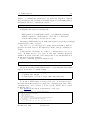
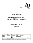
4.3
Connector reference
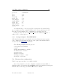
R
The following is a list of all connector part numbers used on the Neon
platform for use in identifying mating parts for your application. Note that
Boundary Deviceswill periodically switch vendors for these parts, but will
notify you of any changes that require a new mating part.
December 28, 2005
Revision 2.8
December 28, 2005
Figure 2: Connector Pin-outs
Revision 2.8
J4
J1
J19
1
1
J16
+ 3.3 VOLTS
A
B
THE DOT ON EACH CONNECTOR DESIGNATE PIN 1
NOTE
PIN 10
PIN 8 GPIO 0 ON CPU UNBUFFERED (ONLY 3.3 VOLT TOLERANT
PIN 7 GPIO 0 ON CPU UNBUFFERED (ONLY 3.3 VOLT TOLERANT
PIN 5 GPIO 3 ON CPU UNBUFFERED (ONLY 3.3 VOLT TOLERANT
PIN4 GROUND
1
1
D
E
C
J22
1
J7
J1
J9
Date:
Size
A
Title
D
Sunday, June 26, 2005
Sheet
Document Number
BOUNDARY DEVICES ALL RIGHTS RESERVED
NEON BOARD IO PIN-OUT
MINUS INPUT
PLUS INPUT
POWER
PIN 1 MICROPHONE
PIN 2 MICROPHONE
PIN4
PIN3 GENERAL PURPOSE OUTPUT
PIN2 GENERAL PURPOSE OUTPUT
1
E
of
1
1
SPEAKER MINUS
J6 INTERNAL
INTERNAL SPEAKER PLUS
STERIO OUTPUT
10/100 ETHERNET
USB MASTER
+5 V INPUT CENTER + BARREL 2.2 MM
J18
J10
J12
1
PIN1 GENERAL PURPOSE OUTPUT
J81 1J13
J14
1
PIN 1 IS GPO(GENERAL PURPOSE OUTPUT)
PIN 2 DRY CONTACT OUTPUT
PIN 3 DRY CONTACT OUTPUT
PIN 4 GPI(GENERAL PURPOSE INPUT)
PIN 5 GPI(GENERAL PURPOSE INPUT)
PINS 6,7,8,9,10 IS GROUND
INVERTER CONNECTOR
JTAG CONNECTOR
Rev
{RevCode}
1
2
3
4
Connector reference
1
1
J23
1
J21
J2
1
PIN 1,2,3,6,9 NO CONNECTION
4 WIRE TOUCH
PIN1 X+
PIN2 Y+
PIN3 XPIN4 Y-
USB SLAVE
UART 1
PIN1 REQUEST TO SEND
PIN2 NO CONNECT
PIN3 GROUND
PIN4 DATA OUT
PIN5 DATA IN
PIN6 CLEAR TO SEND
PIN 1 POWER
PIN2 DATA OUT
PIN3 DATA IN
PIN4 GROUND
UART2
HD15 R,G,B ANALOG CONNECTOR
C
5 WIRE TOUCH SCREEN
PIN1 TOP RIGHT PIN2 TOP LEFT PIN3 BOTTOM LEFT PIN4 BOTTOM RIGHT
PIN 5 SENSE
1
2
3
4
B
J16 AND J16 ARE RGB OUTPUT FOR TFT PANEL
A
1
4.3
7
4.4
Electrical characteristics
Description
USB Master
USB Slave
I2C
Ethernet
Stereo Audio
Backlight inverter
MMC/SD
TFT Display
Touch Screen
Serial Port
JTAG
4.4
8
Manufacturer
FCI
SINGATRON
FCI
Halo
Singatron
Molex
AVX
Part
87520-0010B
KS-001-BNW
68897-001
HFJ11-2450E
2SJ-43723N13
53048-0210
14 5638 009 511 862
Molex
FCI
Molex
52207-0590
68897-001
53048-0810
Electrical characteristics
December 28, 2005
Revision 2.8
9
5
Software features
R
As provided by Boundary Devices, the Neon
board supports either WinR or Linux.
dows CE 5
To simplify the installation of either, the Das U-Bootboot loader is installed on our evaluation boards, and two MMC cards are shipped to allow
the use of either operating system.
5.1
Das U-Boot
The Das U-Boot Boot Loader is a full-featured loader for either Linux or
Windows CE that supports a wide variety of options for loading your Operating System and application.
Boundary Devices ships U-Boot both as a binary image and as source
code in the form of a patch that adds support for either Neon or BD-2003
devices.
The binary image may be burned directly to sector zero of the on-board
flash.
The source code will require a set of Linux or Cygwin(Windows) tools
for cross-compilation. The following section will detail the requirements and
steps for building.
5.1.1
Requirements for building under Linux
Since the Das U-Boot project uses GNU tools, most of the required components will generally be available on a GNU/Linux system.
The three pieces which may not commonly be installed are the bzip2
and wget packages and an ARM cross compiler.
Boundary Devices typically uses GCC-2.95.3 to create U-Boot images,
since that matches what we use to build the Linux image to run on the
Neon itself, but the binary distribution of GCC-3.4.3 from GNUARM is a
nice alternative.
5.1.2
Requirements for building under Windows with Cygwin
There are two primary requirements for building under Windows.
The first, Cygwin, provides a set of Unix utilities under the Windows
operating system. Since the Cygwin installer allows components to be selected individually, the following list shows the requirements for building a
R
support. Note that this list is probably
Das U-Boot image with Neon
incomplete, but these should be the only required items which differ from
the Cygwin installation defaults.
December 28, 2005
Revision 2.8
5.1 Das U-Boot
10
Base/diffutils
Devel/binutils
Devel/gcc
Devel/make
Devel/patchutils
Utils/bzip2
Web/wget
The second requirement for building is the X-Scale cross-compiler itself.
The GNUARM project provides a wealth of information needed to build a
cross-compiler for ARM processors. Thankfully, it also provides an installer.
As of this writing, Boundary Devices currently uses the GCC-3.4.3 package
for Cygwin.
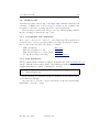
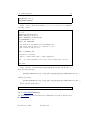
5.1.3
General build steps
Quick start:
wget http://easynews.dl.sourceforge.net/sourceforge/u-boot/u-boot-1.1.2.tar.bz2
bzcat u-boot-1.1.2.tar.bz2 | tar -xvf wget http://boundarydevices.com/u-boot-2005-10-21.patch.gz
gunzip u-boot-2005-10-21.patch.gz
patch -p0 <u-boot-2005-10-21.patch
cd u-boot-1.1.2
CROSS_COMPILE=arm-elf- make neon_config
-------- U-Boot Boundary Devices Specific Configuration Script -------Choose display type (DA640X240 DA320X240 DA800X480 DA640X480 DA240X320 DA1024X768) []: DA1024X768
answer
Choose hardware type (NEONB NEON BD2003) [NEON]:
answer
Choose software type (WINCE LINUX) []: WINCE
answer
Include minidebug (y n) []: y
answer
CPU speed (100 200 300 400) []: 400
answer
Configuration successful.
make
Explanation.
The first four lines retrieve and extract the Das U-Boot sources and add
R
support for the Neon
and BD-2003 devices.
R board itself, and finally, build
The last two lines configure for the Neon
a U-Boot binary. The prompts allow you to select the compile-time defaults
for the display, operating system, and CPU speed. Including minidebug
in your U-Boot image allows you to access the debugger while developing
U-Boot scripts.
When complete, you’ll find a file named u-boot.bin in your u-boot-1.1.2
directory.
5.1.4
Tailoring U-Boot for your application
The Boundary Devices patches (uboot neon bd2003.diff) make a variety of
decisions about the boot process which may not match with the needs of
December 28, 2005
Revision 2.8
5.1 Das U-Boot
11
your application.
In general, the file u-boot-1.1.2/include/configs/neon.h defines these
choices.
In particular, the distributed copy currently expects a Windows BMP
file named bdlogo.bmp to be present on the MMC card and writes it to the
display, then loads an operating system image from a file named nk.nb0 to
RAM address 0xa0030000 and executes it.
Both of these are defined by the lines which resemble this:
#define CONFIG_BOOTCOMMAND
"mmcinit; " \
"fatload mmc 0 a0000000 init.scr ; " \
"autoscr a0000000 ; "
As mentioned previously, the Das U-Boot Boot Loader is a very capable
loader with support for USB and network boot, including BOOTP/DHCP,
and NFS mounting support. Please refer to the Das U-Boot website for
details.
December 28, 2005
Revision 2.8
5.1 Das U-Boot
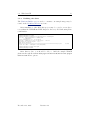
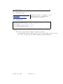
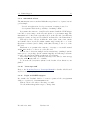
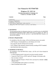
5.1.5
12
U-Boot Memory layout
The following diagram shows the general layout of RAM within Das U-Boot.
0xA4000000
0xA3FF8000
0xA3FF7FFF
0xA2000000
0xA1FFFFFF
32K segment used for page tables.
Page Tables
Unused RAM
Unused High
Extra space between Das U-Boot and 32MB
boundary
Tail of 32MB
0xA1F00000+
The Das U-Boot image is loaded 1MB below
the 32MB boundary
0xA1EFFFFF0xA1EFFFFF-
The heap and stack are allocated in space
preceding the U-Boot image. 1
Heap and Stack
Frame Buffer for BD-2003
0xA1EFFFFF-0xA1EFFFFF-- Unused Low RAM
Revision 2.8
Frame Buffer
0xA0000000
December 28, 2005
Das U-Boot image
0xA1F00000
0xA1EFFFFF
Unused Low
5.1 Das U-Boot
5.1.6
13
U-Boot Init Script
The Das U-Boot boot loader comes with scripting facilities in the form of
the Hush parser and the autoscript command. You should notice when first
compiling the package that the Boundary Devices sample uses this to defer
most board initialization to the MMC card. It does this by setting the
CONFIG BOOTCOMMAND environment variable as follows.
#define CONFIG_BOOTCOMMAND
"mmcinit; fatload mmc 0 a0000000 init.scr ; autoscr a0000000 "
In English, this instructs U-Boot to initialize the MMC/SD card driver,
load a file named init.scr from the card to address A0000000 (the start of
RAM), and execute the script from that memory address. This little bit of
scripting effectively passes all responsibility of what to do at boot time to
the MMC card.
Think of it as a Das U-Boot version of AUTOEXEC.BAT.
The sample script is defined in u-boot-1.1.2/board/neon/init.script and
performs the following steps.
1. Loads and displays a logo. The script looks for an image file named
logo.bmp on the MMC/SD card. If found, it displays the logo on the
LCD panel. We recommend that you place a splash image of a size
matching your display on the MMC card. Note that the bitmap must
be an 8-bit color bitmap.
2. Loads and runs Windows CE. Next, the script attempts to load
NK.nb0 from the MMC/SD card and run it.
As mentioned earlier, the initialization has been mostly deferred to the
MMC/SD card, so the compiled script (init.scr) must be placed on the
card itself. The script is compiled using the Das U-Boot mkimage tool
during the U-Boot build process.
The following list is a recap the expected content of the MMC/SD card
when using the Boundary Devices initialization script.
Filename
init.scr
logo.bmp
NK.nb0
Description
Compiled initialization script
8-bit color splash image
Windows CE image
December 28, 2005
Revision 2.8
5.2
Windows CE
5.2
14
Windows CE
R
As mentioned earlier, the Neon
board ships with a runnable Windows CE
5.0 image on MMC card. A Board Support Package is also available and
necessary to tailor the operating system for a given application.
The following sections describe the process of producing an image matchR
ing the one shipped with the Neon
board.
5.2.1
Prerequisites and components
R application
Most of the tools needed to create a bootable Windows CE 5
R board are provided by Microsoft. The following is a complete
for the Neon
list of components and where they may be obtained.
R
Windows CE 5
Embedded Visual C++ 4.0
Embedded Visual C++ Service Pack
R
Neon
Board Support Package
5.2.2
Microsoft
Microsoft
Microsoft
Boundary Devices
BSP Installation
The Neon BSP is made available as a Windows installer file on the Boundary Devices
website. This file defines a single BSP for the BD2003 and SM501-supporting
variants. Installation consists of running the .msi file.
c:\> wget http://www.boundarydevices.com/bsp20050413.msi
c:\> .\bsp20050413.msi
Please check the Documentation page for details about the latest revision
of the Windows CE BSP.
As a reference tool for the content of the BSP, you should consider using
MSI2XML to view the content.
December 28, 2005
Revision 2.8
5.2
Windows CE
5.2.3
15
Building the demo
The Platform Builder project used to construct our sample image may be
found on the Boundary Devices web site.
After installation of the BSP, this project may be copied to a new directory within the WINCE500 PBWorkspaces directory and built using Platform Builder.
C:\WINCE500\PBWorkspaces>md bdWeb
C:\WINCE500\PBWorkspaces>cd bdWeb
C:\WINCE500\PBWorkspaces\bdWeb>wget http://boundarydevices.com/bdWeb.pbxml
--17:37:40-- http://boundarydevices.com/bdWeb.pbxml
=> ‘bdWeb.pbxml’
Resolving boundarydevices.com... 66.113.228.134
Connecting to boundarydevices.com[66.113.228.134]:80... connected.
HTTP request sent, awaiting response... 200 OK
Length: 45,478 [text/plain]
100%[============================================================================>] 45,478
17:37:40 (58.90 KB/s) - ‘bdWeb.pbxml’ saved [45478/45478]
58.90K/s
C:\WINCE500\PBWorkspaces\bdWeb>.\bdWeb.pbxml
C:\WINCE500\PBWorkspaces\bdWeb>
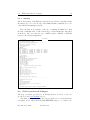
After this is done, you should be able to build the sample WinCE
platform through the Build OS|Sysgen and Build OS|Build and Sysgen
Current BSP menu options.
December 28, 2005
Revision 2.8
5.3
Linux Support
5.3
16
Linux Support
The Linux Environment for Boundary Devices boards consists of four primary pieces, a toolchain, the kernel and device drivers, a user-space build
tool based on PTXDist and a Javascript runtime used to demostrate the
capabilities of the hardware.
5.3.1
Crosstool Linux Toolchain
Before the kernel and applications can be built, it is first necessary to have
a cross-compiler toolchain.
The following examples show how we at Boundary Devices set up our
toolchains. Please refer to the crosstool site for more complete instructions.
First, you’ll need to download and unpack crosstool;
$ wget http://kegel.com/crosstool/crosstool-0.37.tar.gz
$ tar zxvf crosstool-0.37.tar.gz
As described in the crosstool Quick Start guide, the next step is to choose
a starting point with one of the demo build scripts. We’re currently using
demo-arm-xscale.sh with the following settings (GCC 3.4.3 with Glibc
version 2.3.5):
TARBALLS_DIR=/armArchives
RESULT_TOP=/opt/crosstool
eval ‘cat arm-xscale.dat gcc-3.4.3-glibc-2.3.5.dat‘ sh all.sh --notest
We also build the compiler to use software floating point in user space,
rather than hardware floating point (which traps to the kernel). To do this,
modify arm-xscale.dat and add the --with-soft-float and --without-fp
flags as shown below.
GCC_EXTRA_CONFIG="--with-cpu=xscale
GLIBC_EXTRA_CONFIG="--without-fp"
--enable-cxx-flags=-mcpu=xscale --with-float=soft"
Also, we typically change the TARGET to read as follows:
TARGET=arm-linux
because arm-linux-gcc is just too long!
Having completed these edits, you can execute the script as follows:
sh demo-arm-xscale.sh
December 28, 2005
Revision 2.8
5.3
Linux Support
17
Note that this will take a looong time2 . Find something else to do while
you wait.
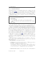
When complete, you should find a whole slew of programs in your
/opt/crosstool/gcc-3.4.3-glibc-2.3.5/arm-xscale-linux-gnu/bin/ directory:
-rwxr-xr-x
-rwxr-xr-x
-rwxr-xr-x
-rwxr-xr-x
-rwxr-xr-x
-rwxr-xr-x
-rwxr-xr-x
-rwxr-xr-x
-rwxr-xr-x
-rwxr-xr-x
-rwxr-xr-x
-rwxr-xr-x
-rwxr-xr-x
-rwxr-xr-x
-rwxr-xr-x
-rwxr-xr-x
-rwxr-xr-x
-rwxr-xr-x
-rwxr-xr-x
-rwxr-xr-x
-rwxr-xr-x
-rwxr-xr-x
5.3.2
1
2
2
2
1
1
2
2
2
1
1
1
2
2
1
1
2
1
1
1
2
1
username
username
username
username
username
username
username
username
username
username
username
username
username
username
username
username
username
username
username
username
username
username
cvsd
cvsd
cvsd
cvsd
cvsd
cvsd
cvsd
cvsd
cvsd
cvsd
cvsd
cvsd
cvsd
cvsd
cvsd
cvsd
cvsd
cvsd
cvsd
cvsd
cvsd
cvsd
1900724
1960214
3339533
331791
1855723
331290
331791
330887
330887
16265
102084
2373278
2622683
1937609
2454999
2595563
1960209
429743
1806673
1780595
2454994
14395
Jul
Jul
Jul
Jul
Jul
Jul
Jul
Jul
Jul
Jul
Jul
Jul
Jul
Jul
Jul
Jul
Jul
Jul
Jul
Jul
Jul
Jul
18
18
18
18
18
18
18
18
18
18
18
18
18
18
18
18
18
18
18
18
18
18
20:48
20:48
20:48
21:35
20:48
21:35
21:35
21:35
21:35
21:35
21:35
20:48
20:48
20:48
20:48
20:48
20:48
20:48
20:48
20:48
20:48
21:47
arm-linux-addr2line
arm-linux-ar
arm-linux-as
arm-linux-c++
arm-linux-c++filt
arm-linux-cpp
arm-linux-g++
arm-linux-gcc
arm-linux-gcc-3.4.3
arm-linux-gccbug
arm-linux-gcov
arm-linux-gprof
arm-linux-ld
arm-linux-nm
arm-linux-objcopy
arm-linux-objdump
arm-linux-ranlib
arm-linux-readelf
arm-linux-size
arm-linux-strings
arm-linux-strip
fix-embedded-paths
Crosstool Embedded (Das U-Boot) Toolchain
The instructions above can be followed to create a toolchain suitable for
cross-compiling Arm-Linux programs on a host machine. The needs for
building the boot loader are a bit different, though. In particular, the ’glibc’
reference above refers very specifically to userspace ”C” and ”C++” libraries
that defer much of their I/O to the Linux kernel itself through the use of
system calls.
Under Das U-Boot, no such system calls exist. In order to support this,
we need to build a Cross-compiler with a different set of switches. Thankfully, the current crosstool distribution supports that as well through the
use of a small library known as newlib from Red Hat.
The next couple of steps will do just that.
First of all, create a file named
crosstool-0.37/contrib/newlib/arm-elf-newlib-1.12.0.dat
and paste the following content into it.
TARGET=arm-elf
TARGET_CFLAGS="-O2"
BINUTILS_DIR=binutils-2.14
BINUTILS_URL=ftp://ftp.gnu.org/pub/gnu/binutils
NEWLIB_DIR=newlib-1.12.0
NEWLIB_URL=ftp://sources.redhat.com/pub/newlib
2
1 hr, 15 minutes on a 1GHz Athlon w/512MB of RAM
December 28, 2005
Revision 2.8
5.3
Linux Support
18
GCC_DIR=gcc-3.4.3
GCC_EXTRA_CONFIG=
Then, create a shell script named
following content.
crosstool-0.37/contrib/newlib/arm-elf.sh
with the
#!/bin/sh
set -ex
TARBALLS_DIR=/armArchives
RESULT_TOP=/opt/crosstool
export TARBALLS_DIR RESULT_TOP
GCC_LANGUAGES="c,c++"
export GCC_LANGUAGES
# You should do the mkdir before running this,
# and chown /opt/crosstool to yourself so you
# don’t need to run as root.
mkdir -p $RESULT_TOP
# Build the toolchain.
# Takes a couple hours and a couple gigabytes.
eval
‘cat arm-elf-newlib-1.12.0.dat‘ sh all-newlib.sh --notest
echo Done.
Next, edit the contrib/newlib/getandpatch-newlib.sh file and replace the line that says:
getUnpackAndPatch ftp://ftp.gnu.org/pub/gnu/gcc/$GCC_DIR.tar.gz ;;
with the following
getUnpackAndPatch ftp://ftp.gnu.org/pub/gnu/gcc/$GCC_DIR.tar.bz2 ;;
Then, run the script like so.
$ time sh arm-elf.sh
5.3.3
GNUARM binaries
The GNUARM site also has binaries for Linux-X86, though we haven’t used
them.
December 28, 2005
Revision 2.8
5.3
Linux Support
5.3.4
19
Kernel 2.4.19
Arm-Linux kernel version 2.4.19
PXA Patches
Boundary Devices patches
5.3.5
Linux kernel patches for ARM processors
Intel PXA support for ARM-Linux
Boundary Devices support
Kernel 2.6
wget http://www.kernel.org/pub/linux/kernel/v2.6/linux-2.6.11.11.tar.bz2
bzcat linux-2.6.11.11.tar.bz2 | tar xvf wget http://boundarydevices.com/boundary-2.6.11.11-2005-11-17.patch.bz2
cd linux-2.6.11.11
bzcat ../boundary-2.6.11.11-2005-11-25.patch.bz2 | patch -p1
cp arch/arm/configs/neon_config ./.config
yes "" | make ARCH=arm CROSS_COMPILE=arm-linux- oldconfig
make ARCH=arm CROSS_COMPILE=arm-linux- uImage
Notes:
Five Wire touch screen support requires setting
Sound|OSS|Multimedia Capabilities Port drivers|UCB 1400|Five wire
(or edit .config and set CONFIG_UCB1400_TS_FIVE_WIRE=y)
December 28, 2005
Revision 2.8
5.3
Linux Support
5.3.6
20
Userland build tool
As mentioned before, we at Boundary Devices use a variant of an older
version of the PTXDist tool to keep track of the cross-compilation needs
for various libraries. This allows inter-library dependencies to be expressed,
and also allows the canonical source locations to be used during a build.
This should really be better documented, but the short and simple build
instructions are as follows.
$
$
$
$
wget http://boundarydevices.com/userland_20051126.tar.gz
tar zxvf userland_20051126.tar.gz
cd userland
make menuconfig
-- at a minimum, you’ll need to set an archive path to
a writable directory, and validate your kernel and toolchain
paths.
$ make cramfs
Note that this takes a while (over an hour on a typical machine), but
will result in a cramfs image being created in the userland/ directory.
Also note that installation of the [[tinylogin]] program requires privileges
to [[setuid root]]. Because of this, the makefile rules/tinylogin.mak uses the
[[sudo]] program. If you don’t have sudo installed, this process will fail.
If you do, you may see a password prompt very near the end of the build
process (while installing tinylogin into the root filesystem). To avoid this,
you can either set your [[sudo]] timeout to something large and perform a
sudo operation before kicking off the build, or do as I do and set it negative
(no timeout). For reference, refer to this document or [[man sudoers]].
The choice of cramfs is for illustration (and because it requires that
everything be compiled and installed). Refer to Section 5.3.8 for more details about the choices available and decisions you need to make regarding
deployment.
More specifically, the userland build tool is designed to allow reproducible builds of entire userland filesystems and device nodes for embedded
Linux distributions.
The general flow of the make is as follows:
1. Configure the system through the kconf tool. This step produces a
file named .config in the userland directory.
You should save this file for future reference when you have a set of
choices that meet your needs. By saving it off to say good.config,
you can copy it back to .config and reproduce the build later.
2. Get the source code for each component. Since downloading all of
December 28, 2005
Revision 2.8
5.3
Linux Support
21
the components may take a while, it is often useful to perform this
step by itself after configuration.
The get makefile target can be used to perform this step.
Note that the original web locations are generally used for each library
supported by the userland build. This is generally a good thing, but
also means that things sometimes move.
We try to keep a set of archives on the Boundary Devices website for
use when the original sources are unavailable.
Look here if you can’t find something.
3. Build libraries under build/ the system through the kconf tool.
As mentioned earlier, the build tool allows you to express inter-library
dependencies in their makefile packets.
The packets for each component are stored in userland/rules and
consist of both a configuration piece *.in and build instructions *.make.
The install target can be used to simply build the components without making a root filesystem.
4. Install libraries into install/. This mingling of various libraries is
done to allow simplified include file and library references for dependent packets.
5. Build a root filesystem under root/. This step gathers all of
the executable portions (applications and shared libraries) for each
component into a root filesystem image. Scripts are also commonly
installed, as are any supporting configuration files (under root/etc).
The rootfs target can be used to create the root filesystem without
creating a flattened image.
6. Build a device table. This step uses the kernel configuration file to
create devices.txt, suitable for use with genext2fs, mkcramfs, or
mkfs.jffs2.
The devices target can be used to create the device table without
performing any other build steps.
7. Flatten the root filesystem into any of cramfs, initrd, or JFFS2
images for placement in flash or SD card.
December 28, 2005
Revision 2.8
5.3
Linux Support
5.3.7
22
Userland libraries and applications
The following libraries and applications are included in the userland build.
Name
Description
Link
bdScript
Boundary Devices Javascript Boundary Devices
Busybox
busybox
Shell and utilities
cramfs tools
Cramfs Utilities
SourceForge
libcurl
HTTP library and more
libcurl project
e2fsprogs
Ext2 Filesystem Utilities
SourceForge
flash
GPL’d Flash Library
Swift Tools
freetype
FreeType Text Rendering
The FreeType Project
jpeg
JPEG image library
Independent JPEG Group
Javascript
Javascript library
Mozilla Project
ID3 Tag Library MP3 ID tag library
MAD Project
MP3 Library
MPEG Audio Decoder
MAD Project
libpng
PNG image library
libpng project
libungif
GIF decompression
SourceForge
libmpeg2
MPEG decoder library
libmpeg2 project
openssh
SSH Application
OpenSSH project
openssl
SSL Library
OpenSSL project
udhcp
DHCP Client/Server
Busybox
zlib
zlib compression library
ZLib project
December 28, 2005
Revision 2.8
5.3
Linux Support
5.3.8
23
Notes about userland root filesystems
Section 5.3.6 refers to the cramfs target without really indicating its’ use.
The cramfs option is one of three primary ’bundled’ targets:
1. cramfs - Creates a single file as a read-only, gzip-compressed image of
a filesystem tree. When you can nail down the content of your filesystem, this is a great choice, providing the fastest boot time (around 7
seconds on a PXA-255) and complete immunity to corruption. This
filesystem is often used in conjunction with read-write filesystems (ram
disk for volatile data, or VFAT for semi-static data).
Requires cramfs support in the kernel (Miscellaneous Filesystems—Compressed
ROM file system support).
2. jffs2 - Creates a single file as a read-write, gzip-compressed image of
a filesystem tree. This is useful for placement in flash, and is fairly
immune to corruption at the cost of extra time for validation at boot
(typically 30-45 seconds for a 32MB filesystem).
Requires JFFS2 support in the kernel (Miscellaneous Filesystems—Journalling
Flash File System v2 ).
3. mmcinitrd/mmcinitrd.u-boot - Creates a single file as a readwrite, uncompressed image of a filesystem tree suitable for use as an
initial RAM disk (initrd ).
It requires the following options in the kernel:
Loopback device support
Device Drivers—Block Devices
Initial RAM Disk support Device Drivers—Block Devices
In addition, this target makes a bunch of other choices for you. Since
this is a bit involved, discussion of the steps is deferred to Section
5.3.9.
The Makefile instructions for each of these is at the tail-end of the
userland Makefile (userland/Makefile).
Refer to that file for details, but the bundled image for each is created
by performing a single command specifying an output file (the image), a
path name to a directory tree, and the devices.txt file.
Typical usage for the initrd target is to have the boot loader load the
image into RAM. Das U-Bootprovides support for handing the load address
to the Linux kernel through the bootm command.
Both the cramfs and JFFS2 images may also be mounted directly from
flash EEPROM using Linux MTD block devices. U-Boot’s support for passing
December 28, 2005
Revision 2.8
5.3
Linux Support
24
Linux boot command line parameters to the kernel also helps here. Typical
usage includes is of the following form, which supplies both the MTD partition
information and the root filesystem reference:
mtdparts=phys_mapped_flash:1024k(armboot),256k(params),-(rootfs1) root=/dev/mtdblock3 rootfstype=cramfs
In English, this reads as something like:
MTD partitions are 1MB (named armboot), 256K(named params),
with the remainder of flash named rootfs1. The root filesystem
is in the third partition, and its’ type is cramfs.
Mounting a JFFS2 image is done in the same manner, except the rootfstype
parameter has a value of jffs2.
The U-Boot boot loader supports copying data from RAM to flash for
upgrades and such. Refer to the unprotect, erase, and cp commands for
details.
A third means of mounting one of these root filesystems is to use a loop
device. In Linux jargon, a loop device is a file that contains a filesystem
within it. Both the initrd and cramfs images may be used in this fashion as
shown in the following examples.
Mount a cramfs file (by far the simplest case).
~ $ sudo mount -o loop -t cramfs ~/cramfs.img /mnt/cramfs
Mount an ext2 image (Only slightly harder because mmcinitrd is actually
gzipped and needs to be gunzip’d first).
~ $ cp -f mmcinitrd mmc.img.gz
~ $ gunzip mmc.img.gz
~ $ sudo mount -o loop -t ext2 ~/mmc.img /mnt/ext2
To mount a JFFS2 image a bit more is needed. Your kernel needs to
have mtd and mtdblock support compiled in or installed as modules. Then,
a mtdram device can be created, you can copy the JFFS2 data to it and
mount the device.
The Handhelds site has more information on the topic.
~ $ sudo /sbin/insmod mtdram total_size=32768 erase_size=256
Using /lib/modules/2.4.23_pre8-gss-r2/kernel/drivers/mtd/devices/mtdram.o
~ $ sudo dd if=jffs2.img of=/dev/mtd0
10809+1 records in
10809+1 records out
~ $ sudo /sbin/insmod mtdblock
Using /lib/modules/2.4.23_pre8-gss-r2/kernel/drivers/mtd/mtdblock.o
~ $ sudo mount -r -t jffs2 /dev/mtdblock/0 /mnt/jffs2/
~ $ ls /mnt/jffs2/
bin etc lib linuxrc opt proc sbin sysfs tmp usr var
December 28, 2005
Revision 2.8
5.3
Linux Support
5.3.9
25
mmcinitrd.u-boot
The mmcinitrd.u-boot userland Makefile target has a lot of parts, but its’
goal is simple
Provide an application developer a means of staying focused on
development without the possibility of trashing a flash.
It presumes the existence of an SD card formatted with the VFAT filesystem, and a cramfs image on the SD card (in the root as cramfs.img). The
mmcinitrd.u-boot file is also typically loaded on the SD card, but that isn’t
strictly necessary, as long as it is available and handed to the Linux kernel.
Through a series of steps, it links the /bin, /lib, /usr, /var, /sbin,
and /share directories from within cramfs.img, leaving the root of the
filesystem read-write (and volatile), with /mmc referring to the root of the
SD card.
Furthermore, it presumes the existence of a script or executable named
linux init in the root directory of the SD card.
This is done both as an example and as a useful way of nailing down the
static pieces of a package (in the cramfs.img file) and allowing read-write
access to the filesystem during application development.
The linux init script on the SD card may be modified to start an app
directly, without any risk of boot failure.
Look at the file /etc/init.d/rcS for the details of how this is accomplished.
5.3.10
Javascript stuff
Refer to the Boundary Devices’ Javascript Manual for details of the Boundary Devices scripting application.
5.3.11
Login and SSHD support
By default, the Userland build tool creates a password file /etc/passwd
with a root password of BoundaryDevices.
This is only needed when connecting over sshd.
Use the menuconfig make target to change this.
December 28, 2005
Revision 2.8
26
6
6.1
Development Tools
minidebug
minidebug is a small (under 16k) debugger designed to fit completely within
the instruction cache on the PXA-255 processor to allow testing of boards
even in the absence of ROM or RAM.
It also includes features to download over either serial or Ethernet, allows the display and manupulation of registers and memory, and supports
controlled execution through breakpoints and data watchpoints.
Upon entry, minidebug generally displays a dot (.) prompt, sometimes
pre-pended by a string that looks like $S00#b3. Fear not. The $S00#b3
string is used to allow minidebug to work in conjunction with the gdb debugger on the attached system.
The following is a list of commands that can be issued at the dot prompt.
Note that this list can also be retrieved through minidebug by entering a
question mark (?).
command
BC
BE
BS
BURN
E
D
DL
DLW
G
GL
GG
R
SSID
T
TT
V
WC
WR
WRW
WW
?
params
address
address
address
address range
address
address value
address
address
address
address
address range
address
address
address
address
December 28, 2005
description
Breakpoint clear
Breakpoint examine
Breakpoint Set
Burn image at address range to flash
Examine and modify memory
Deposit
Start XModem for serial download
Download wireless
Go
Go Linux
Go no cache clear
Display content of registers
Set Wireless SSID string
Trace
Trace no cache clear
Verify content of flash
Watch clear
Watch read
Watch read/write
Watch write
Show this list of commands
Revision 2.8
6.2
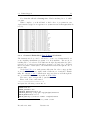
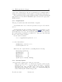
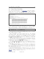
JTAG system-level debugger
6.1.1
27
mdebug
The mdebug image adds Ethernet and wireless download capabilities using
R . The SSID and DLW commands above are
the Blast protocol to the Neon
only valid when mdebug is present.
The following is an example of the use of mdebug and DLW. Note that
the first commands used download mdebug to address A1C00000 and run it
from there. Also note that the use of DLW requires a DHCP or BOOTP
server for IP address assignment.
DLW example
. dl a1c00000
CCCCCCCCCCC
enter binary file name: mdebug
CCCCCCCCCCCCCCCCCCCCCCCCCCCCCCCCCCCCC.....................
...................................................
73620 bytes, 72 packets, 0 retrys
OK A1C00000-A1C12000
. g a1c00000
$S00#b3
Reset A0008000
R0: 00000000 R1: 0000014C R2: 00000001 R3: 00000060
R4: A1F1D540 R5: A1F22B1C R6: A1E9BECC R7: 00000002
R8: A1E9BFDC R9: A1E9BE88 SL: 00000000 FP: A1E9BE10
IP: A1E9BE14 SP: A0003400 LR: A0008000 PC: A0008000
CPSR 600000D3 FP0: 0000000000
.
. dlw a0008000
Boundary Devices 1
SMC91C11xFD
%s: PHY=LAN83C183 (LAN91C111 Internal)
%s: PHY remote fault detected
%s: Ethernet Link Detected
%s: PHY 100BaseT
%s: PHY Half Duplex
valid mac address
00:50:C2:06:30:8F
..........DISC:received 0x012C bytes of reply
done
REQ:received 0x012C bytes of reply
done
router at 192.168.0.1
DNS server at 68.2.16.25
DNS server at 68.2.16.30
DNS server at 68.6.16.30
DHCP success, using IP 192.168.0.14
ready to receive file
enter binary file name: cramfs.img
...........................................................
................
transmitted in 52 seconds
.[eof]
lost 0x00000000 packets
[eof] in 52 seconds
sent 19783680 bytes of file to 192.168.0.14
Error free!!!
0x012DE000 bytes written to buffer at A0008000 A12E6000
6.2
JTAG system-level debugger
The jtag executable provided by Boundary Devices is based on the one
provided by the Open WinCE project.
Our main goals in developing the jtag program were to aid in hardware
debugging and to allow the first flash EEPROM image to be burned onto
December 28, 2005
Revision 2.8
6.2
JTAG system-level debugger
28
a new device. That said, we also use it extensively as a terminal emulator
during development and have added a number of extensions for that purpose.
The current release supports the PXA250, PXA255, PXA270, and SA1100
(lart untested). It checks the IDCODE register and uses the appropriate
BSDL structure.
6.2.1
Requirements
The jtag executable runs either under Linux or Cygwin.
Under Linux, there are no known dependencies except for libc and libstdc++.
Under Cygwin, the jtag executable requires the ioperm driver to be installed. This driver makes the ioperm() and iopl() system calls available
under Windows for access to the serial and parallel ports. Note that after
the cygwin package is installed, you still need to enable the driver through
the use of the ioperm executable
For the cmd.exe inclined:
c:\> c:\cygwin\bin\ioperm.exe -v -i
or for the bash-inclined:
user@machine ~/u-boot-1.1.2
$ /bin/ioperm.exe -iv
Either way, the output should be something like the following.
Installing ioperm.sys...
OpenSCManager
ok
CreateService
ok
OpenService
ok
StartService
ok
ioperm.sys is already running.
6.2.2
Startup Options
jtag -t Generate a square wave on the processor pins.
This option allows pins to be checked in a sequence defined by the
hardware file. A ’+’ or ’-’ keypress will scroll forward or backward
through the list. Also, pin name can be entered directly. Entering
GP0 will generate a square wave on GP0. A ’ ?’ will list matching pin
names. Entering GP? will list all gpio pins.
December 28, 2005
Revision 2.8
6.2
JTAG system-level debugger
29
jtag -i Identify the flash part used
This option tries to identify the part number of the Flash EEPROM.
Currently supported parts are 28F160F3B, 28F320J3A, 28F128J3A,
28F320C3B, and 28F320S3, though not all have been tested. It should
be relatively easy to add new parts.
jtag -f Generate the appropriate signals to program a flash.
This option is rarely used, since we normally program the flash through
the minidebug software.
jtag -c Download code to the mini and main instruction cache.
This option is used to load a file into the instruction cache. Usually
-x, -e, -or -d option is used to load minidebug. The -d option just
loads minidebug. The -x option then proceed to dowload a file over
the serial port using xmodem. The -e option dowloads a file using
ethernet (wireless and wired support.) The -ssid option can be used
to specify a wireless essid value to pass to minidebug.
jtag -s Terminal emulator option.
The parallel port is still searched because [Ctrl A] B can be used to
send a JTAG break and attempt to return control to minidebug.
jtag -N Burn the entire flash.
This option can be used to burn a flash for the first time.
It first downloads the file mdebug to ram address A1800000.
Then it executes an ethernet download of the file totalflash.
If successful, it then burns the flash using the minidebug(mdebug)
command BALL (burn all).
December 28, 2005
Revision 2.8
6.2
JTAG system-level debugger
6.2.3
30
Control Keys
Once running, the jtag program responds to a number of command sequences, all beginning with [Ctrl A] .
[Ctrl
[Ctrl
[Ctrl
[Ctrl
[Ctrl
[Ctrl
[Ctrl
6.2.4
A]
A]
A]
A]
A]
A]
A]
B
S
L
T
P
Q
R
Send a break
Send a file using XModem
Toggle logging to jtag.log
Send an ascii file
Choose baud rate
Quit
Hardware reset
Blast protocol
When used with the mdebug image, the jtag program recognizes the startof-download request sent by the device, and will prompt the user for a file
name to send. Refer to the example in the mdebug section for details.
6.2.5
Quick-start download and burn
If you have a minidebug for your platform in the current working directory,
the following sequence shows the process of using it to download and burn
a new u-boot image.
Start debugger.
$ cd ..
$ ./jtag -d
ioport 3bc wrote 5d read ff
using printer port at 378
IDCODE: 69264013 - 0110 1001001001100100 00000001001 1
Halt released
Waiting for stub
LDIC finished
This uses the program minidebug on the arm to download to ram
using the serial port(xmodem protocol) or blast the file using
ethernet
^A Q for quit, ^A B external break, ^A S for sending a file with xmodem,
^A I for sending an RGB bitmap with xmodem, ^A P baudrate
^A T to send an ascii file
DBG-Vector Trap A0008000
R0: 00000000 R1: 0000014C R2:
R4: 0000001E R5: 81A0F288 R6:
R8: 00000000 R9: 81A18774 SL:
IP: 80039094 SP: A0003400 LR:
CPSR 600000D3 FP0: 0000000000
00000000
AAA00010
AAA0001C
8006C8CC
R3:
R7:
FP:
PC:
00000003
000BD784
81A1606C
A0008000
.
To download using serial, use the ’dl address’ command.
Hit [Ctrl A] S to send the file (assumes u-boot.bin in the current directory). After issuing the DL command, the minidebug will begin sending
C’s. These are the start commands for XModem, and signal the readiness
December 28, 2005
Revision 2.8
6.2
JTAG system-level debugger
31
to receive a file. Use the [Ctrl A] S sequence to instruct jtag to prompt
for and send a file using XModem.
To abort the operation, either when prompting for a filename or before,
use [ctrl-C].
. dl a1f00000
CCCCCCCCCCCCCC
enter binary file name: u-boot.bin
CCCCCCCCCCCCCCCC............................................
....................................
81292 bytes, 80 packets, 0 retrys
OK A1F00000-A1F14000
To burn a range of data from RAM to the start of flash, use the ’burn’
command like this. Note that the end address was given above at the end
of the DL response.
. burn a1f00000 a1f14000
Sector 04000000 Erasing Programming Verifying...
Success
December 28, 2005
Revision 2.8
6.3
TeraTerm blast extensions
6.3
32
TeraTerm blast extensions
As an alternative to the jtag executable, Boundary Devices has also produced an extension to the TeraTerm open-source terminal emulator with
R
support for the Blast
protocol.
It has the following benefits over the use of jtag:
• Does not require Cygwin and ioperm
R graphical application, it’s a bit simpler to
• Because it’s a Windows
use and has a file-chooser dialog.
The drawback is that it does not support the jtag hardware connection
or any of the associated features (can’t force a hardware reset, can’t recover
a machine with a trashed flash).
We recommend its use only for non-development needs, or when cabling
the jtag is inconvenient (e.g. during production).
It can be downloaded here.
December 28, 2005
Revision 2.8
6.4
6.4
Using U-Boot Networking
33
Using U-Boot Networking
One of the most useful features of the Das U-Boot loader is its’ ability to
transfer files across a network. As shown below, the dhcp command is
typically used to perform both a BOOTP/DHCP request and transfer a file.
$
$ set bootfile nk4.nb0
$ set serverip 192.168.0.26
$ dhcp
Using MAC Address 00:50:C2:06:30:8F
BOOTP broadcast 1
DHCP client bound to address 192.168.0.14
TFTP from server 192.168.0.26; our IP address is 192.168.0.14
Filename ’nk4.nb0’.
Load address: 0xa0030000
Loading: T T #################################################################
#################################################################
#################################################################
#################################################################
#################################################################
#################################################################
...
#################################################################
#################################################################
done
Bytes transferred = 23068672 (1600000 hex)
$
First of all, the bootfile environment variable is used in the example
above to define the file to transfer. By default, the boot file is computed
using a hex representation of the IP address assigned to the device.
’192.168.0.14’
=> ’0E00A8C0.img’
Used with a tftp server that allows symlinks, this provides a convenient
way to define per-device boot files.
The second thing to note in the example is the use of the serverip
environment variable. This variable defines the IP address of the TFTP
server, in this case ’192.168.0.26’. If your DHCP server allows setting of
the si addr field in the DHCP response (refer to RFC2131 for details), this
value can be automatically provided.
The third thing of interest is the load address (0xa0030000). This value
is defined in neon.h in the CFG LOAD ADDR macro. It may be overridden
through the use of the loadaddr environment variable.
The CONFIG EXTRA ENV SETTINGS macro in configs/neon.h may be
used to assign the proper compile-time defaults for the environment variables
listed above.
The DHCP/BOOTP/TFTP process is relatively fast, even using a slow
protocol like TFTP. The 23MB transfer above took 20 seconds. Much faster
than swapping MMC cards. Slower than mdebug/jtag under Linux, but
faster than Cygwin jtag and blast.
Any server software that supports RFC1350 should work. The standard tftpd daemon under Linux is a good choice. Under Windows, the free
Tftfpd32 by Philippe Jounin is a very nice tool.
December 28, 2005
Revision 2.8
34
7
Configuration Notes
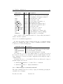
7.1
Display configuration
R
The Neon
supports a variety of LCD panels. The following section describes the process of configuring the board for a known, currently supported
display panel as well as a Das U-Boot utility command for testing settings
on a new panel.
If you know the type of panel at compile time, you can place a selection
from the list below in the Das U-Boot configuration file include/configs/neon.h.
The CONFIG EXTRA ENV SETTINGS macro is used to define a compile-time
choice. If you are using EEPROM to store environment settings, these can
be saved in the environment as well as described below.
Name
qvga portrait
hitachi qvga
sharp qvga
hitachi hvga
sharp vga
hitachi wvga
crt1024x768
Resolution
240 x 320
320 x 240
320 x 240
640 x 240
640 x 480
800 x 480
1024 x 768
Description
Hitachi Quarter VGA 3.5” panel
Hitachi High-Brightness Quarter VGA
Sharp Quarter VGA
Hitachi Half VGA
Sharp 10.4 inch VGA
Hitachi Half VGA
HP SVGA
For example:
#define CONFIG_EXTRA_ENV_SETTINGS "panel=hitachi_hvga" "\0"
Note that this is automatically done as a part of the make neon config
step.
The boot loader settings for the LCD panel will carry through to the
Linux and Windows CE drivers.
R
If you’re using the Neon
with a new panel, you’ll need to determine
and define the following fields for the panel.
December 28, 2005
Revision 2.8
7.1
Display configuration
field name
name
pixclock
type
string
number
xres
yres
act high
hsync len
left margin
right margin
vsync len
upper margin
lower margin
active
crt
rotation
number
number
number
number
number
number
number
number
number
number
number
number
35
description
used to identify the panel
Divisor for the pixel clock. Generally
3 for QVGA, 1 for higher resolution.
Horizontal pixel count
Vertical pixel count
Clock polarity, 0 (default) or 1
Horizontal sync pulse
Idle pixels before leftmost pixel
Idle pixels after rightmost pixel
Vertical sync pulse
Idle rows before topmost
Idle rows after bottom
Active Matrix (1) or Passive (0)
digital LCD(0) or Analog CRT(1)
landscape(0) or portrait(90)
Once you have collected this information, a corresponding entry must be
added to the list of panels.
u-boot-1.1.2/common/lcd_panels.c
To allow the testing of these settings and the use of a different display
without re-compiling, the lcdp boot loader command is available. It may
be used in one of the following ways:
command string
lcdp
lcdp ?
lcdp panelname
lcdp +
description
Show the current lcd panel settings
Show the list of currently supported lcd panels
Select and initialize panelname
Add a new panel (prompts for details)
Note that the boot loader text display will not be updated properly if
the X and Y resolution don’t match the current default display. Use the
bmp commands to test the new panel configuration after using the lcdp +
command string.
As always, the source code is available. The two modules used to support
dynamic display selection are:
• common/cmd lcdpanels.c - defines U-Boot commands
• common/lcd panels.c - display initialization
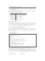
7.1.1
What display is currently selected?
The lcdp command is used for a variety of purposes including querying the
currently selected display.
December 28, 2005
Revision 2.8
7.1
Display configuration
36
$ lcdp
-----------------------------------name
: crt1024x768
pixclock
: 65000000
xres
: 1024
yres
: 768
act_high
: 1
hsync_len
: 200
left_margin
: 24
right_margin
: 161
vsync_len
: 6
upper_margin
: 3
lower_margin
: 29
active
: 0
7.1.2
What displays are supported...?
The lcdp command followed by a question mark will list the currently supported displays. As shown in the following example, the list is extensive
(and extensible, as we’ll show later).
$ lcdp ?
-----------------------------------name
: hitachi_qvga
pixclock
: 0
xres
: 320
yres
: 240
act_high
: 1
hsync_len
: 64
left_margin
: 1
right_margin
: 16
vsync_len
: 20
upper_margin
: 8
lower_margin
: 3
active
: 1
-----------------------------------name
: sharp_qvga
pixclock
: 0
xres
: 320
yres
: 240
act_high
: 1
hsync_len
: 8
left_margin
: 16
right_margin
: 1
December 28, 2005
Revision 2.8
7.1
Display configuration
37
vsync_len
: 20
upper_margin
: 17
lower_margin
: 3
active
: 1
-----------------------------------name
: hitachi_hvga
pixclock
: 1
xres
: 640
yres
: 240
act_high
: 1
hsync_len
: 64
left_margin
: 34
right_margin
: 1
vsync_len
: 20
upper_margin
: 8
lower_margin
: 3
active
: 1
-----------------------------------name
: sharp_vga
pixclock
: 1
xres
: 640
yres
: 480
act_high
: 1
hsync_len
: 64
left_margin
: 60
right_margin
: 60
vsync_len
: 20
upper_margin
: 34
lower_margin
: 3
active
: 1
-----------------------------------name
: hitachi_wvga
pixclock
: 1
xres
: 800
yres
: 480
act_high
: 0
hsync_len
: 64
left_margin
: 1
right_margin
: 39
vsync_len
: 20
upper_margin
: 8
lower_margin
: 3
active
: 1
-----------------------------------December 28, 2005
Revision 2.8
7.1
Display configuration
name
pixclock
xres
yres
act_high
hsync_len
left_margin
right_margin
vsync_len
upper_margin
lower_margin
active
$
7.1.3
:
:
:
:
:
:
:
:
:
:
:
:
38
crt1024x768
65000000
1024
768
1
200
24
161
6
3
29
0
Select a supported display
If you supply a supported panel name on the lcdp command line, the display
controller will be reset with the associated parameters.
$ lcdp hitachi_wvga
found panel hitachi_wvga
panel: 800x480x8
$ lcdp
-----------------------------------name
: hitachi_wvga
pixclock
: 1
xres
: 800
yres
: 480
act_high
: 1
hsync_len
: 64
left_margin
: 1
right_margin
: 39
vsync_len
: 20
upper_margin
: 8
lower_margin
: 3
active
: 1
The selection takes place immediately, so if you have a panel connected,
you should see valid output on the display.
Note that if you change resolutions, the display memory will likely have
mis-aligned data in it. Displaying a bitmap on the display through the use
of the fatload and bmp commands will remedy this situation. Refer to
init.script for an example.
If you want to make your selection stick through a reset, you can save it
through the set and save U-Boot commands.
December 28, 2005
Revision 2.8
7.1
Display configuration
39
$ set panel hitachi_wvga
$ save
Saving Environment to Flash...
Un-Protected 1 sectors
Erasing Flash...
Erased 1 sectors
Writing to Flash... done
Protected 1 sectors
$ reset
resetting ...
$S00#b3
Reset A0008000
U-Boot 1.1.2 (Jun 10 2005 - 22:31:50)
U-Boot code: A1F00000 -> A1F20500 BSS: -> A1F54520
RAM Configuration:
Bank #0: a0000000 64 MB
Flash: 32 MB
panel hitachi_wvga found: 800 x 480
...
7.1.4
Define and test a new display
If you add a plus sign to the lcdp command line, you’ll be prompted for all
of the parameters needed to define a display.
$ lcdp +
name: myDisplay
pixclock: 65000000
xres: 800
yres: 600
act_high: 1
hsync_len: 200
left_margin: 24
right_margin: 161
vsync_len: 6
upper_margin: 4
lower_margin: 29
active (0|1) : 1
-----------------------------------name
: myDisplay
December 28, 2005
Revision 2.8
7.2
Memory size configuration
pixclock
xres
yres
act_high
hsync_len
left_margin
right_margin
vsync_len
upper_margin
lower_margin
active
:
:
:
:
:
:
:
:
:
:
:
40
1694498816
800
600
1
200
24
161
6
4
29
1
As with switching to a known panel, the settings take effect immediately
upon completion of the command. This can be a very quick way to add
support for a new display before committing it to the supported list.
Adding an entry into the lcd panels array in common/lcd panels.c
will provide boot-time support.
7.1.5
Saving settings to Flash EEPROM
All of the descriptions above are useful, but don’t address the issue of persistence. That is performed through the use of the ’panel’ environment variable
and the ’saveenv’ Das U-Boot command.
The following example shows the process.
$ set panel crt1024x768
$ save
Saving Environment to Flash...
Un-Protected 1 sectors
Erasing Flash...
Erased 1 sectors
Writing to Flash... done
Protected 1 sectors
7.2
Memory size configuration
R
The Neon
supports either 32 or 64MB of RAM.
Most of the default boot loader configuration assumes at least 32MB of
RAM is available. In particular, the TEXT BASE variable in board/neon/config.mk
links the uboot.bin image at 31MB from the start of RAM.
December 28, 2005
Revision 2.8
7.3
Upgrading U-Boot
41
Use the PHYS SDRAM 1 SIZE variable in include/configs/neon.h to
specify the actual size for your hardware.
The Windows CE image supports either, but defaults to 32MB. Set the
RAM SIZE 64 MB environment variable in your project to indicate that 64MB
should be present.
The RAM size set in the boot loader is passed to the Linux kernel.
7.3
Upgrading U-Boot
As you might expect, Das U-Boot is stored at offset zero in flash EEPROM
(i.e. at address zero). If you have a new Das U-Boot image (typically
u-boot.bin) on an SD/MMC card, you can upgrade it by first unprotecting
and erasing the first sector of flash, then copying the new image to address
zero as shown below.
$ mmcinit
...
registering device
$ fatload mmc 0 a0008000 u-boot-neon.bin
reading u-boot-neon.bin
134264 bytes read in 271921 ticks, (73 ms),
adler == 0xf0cde398 in 24546 ticks, (6 ms)
$ protect off all
Un-Protect Flash Bank # 1
$ erase 0 3ffff
Erased 1 sectors
$ cp.b a0008000 0 $filesize
Copy to Flash... done
$ cmp.b a0008000 0 $filesize
Total of 134264 bytes were the same
$ reset
After reset, you should see the new build date in the U-Boot banner.
December 28, 2005
Revision 2.8
7.4
7.4
Touch Panel Calibration
42
Touch Panel Calibration
Under Linux, the flash sector at address 0x140000 is used to store the touchscreen calibration settings. If you’re using bdScript startup code, the calibration routine will launch upon first boot if not defined.
Under Windows CE, the touch screen settings are stored on the MMC
card in a file named touch.txt. You’ll need to use the mouse to launch the
touch calibration program.
December 28, 2005
Revision 2.8
7.5
7.5
Ethernet MAC Addresses
43
Ethernet MAC Addresses
Normally, Neon boards come with their MAC addresses pre-programmed
during assembly and test. This is done by using the U-Boot mac command
as shown below.
Invoked without an argument, the command will display the current
MAC address. Used with a single parameter (MAC address with colons
separating each pair of hex digits), the command will allow (re)programming
of the MAC address.
$ mac
mac address ff:ff:ff:ff:ff:ff
$ mac 00:50:c2:06:30:b8
setting mac address to 00:50:c2:06:30:b8
done
December 28, 2005
Revision 2.8