1
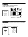
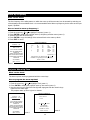
OWNER ’ S M ANUAL
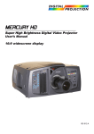
DTV-1200
DTV Capable CRT Projector
TABLE OF CONTENTS
Safety Instructions . . . . . . . . . . . . . . . . . . . . . . . . . . . . . . . . . . . . . . . . . . . . . . . . . . . . . . . . . . . . . . 4
Limited Warranty . . . . . . . . . . . . . . . . . . . . . . . . . . . . . . . . . . . . . . . . . . . . . . . . . . . . . . . . . . . . . . . 8
Connections . . . . . . . . . . . . . . . . . . . . . . . . . . . . . . . . . . . . . . . . . . . . . . . . . . . . . . . . . . . . . .
Power Connection to Projector . . . . . . . . . . . . . . . . . . . . . . . . . . . . . . . . . . . . . . . . . . . . . . . . . .
Source Connections . . . . . . . . . . . . . . . . . . . . . . . . . . . . . . . . . . . . . . . . . . . . . . . . . . . . . . . . . .
RGB Source to Input 3 . . . . . . . . . . . . . . . . . . . . . . . . . . . . . . . . . . . . . . . . . . . . . . . . . . . . . . . .
RGB Source with Composite Sync to Input 4/5 . . . . . . . . . . . . . . . . . . . . . . . . . . . . . . . . . . . . . .
RGB Source with Tri-level Sync to Input4/5 . . . . . . . . . . . . . . . . . . . . . . . . . . . . . . . . . . . . . . . . .
Component Source to Input 4/5 . . . . . . . . . . . . . . . . . . . . . . . . . . . . . . . . . . . . . . . . . . . . . . . . . .
RS-232 Connection . . . . . . . . . . . . . . . . . . . . . . . . . . . . . . . . . . . . . . . . . . . . . . . . . . . . . . . . . . .
.
.
.
.
.
.
.
.
.
.
.
.
.
.
.
.
.
.
.
.
.
.
.
.
.
.
.
.
.
.
.
.
.
.
.
.
.
.
.
.
.
.
.
.
.
.
.
.
10
10
11
12
12
13
13
13
Getting Started . . . . . . . . . . . . . . . . . . . . . . . . . . . . . . . . . . . . . . . . . . . . . . . . . . . . . . . . .
Remote Control & Local Keypad . . . . . . . . . . . . . . . . . . . . . . . . . . . . . . . . . . . . . . . . . . . . . . .
Stationary Image Warning . . . . . . . . . . . . . . . . . . . . . . . . . . . . . . . . . . . . . . . . . . . . . . . . . . . .
Remote Commands to the Projector . . . . . . . . . . . . . . . . . . . . . . . . . . . . . . . . . . . . . . . . . . . .
Projector Address . . . . . . . . . . . . . . . . . . . . . . . . . . . . . . . . . . . . . . . . . . . . . . . . . . . . . . . . . .
.
.
.
.
.
.
.
.
.
.
.
.
.
.
.
.
.
.
.
.
.
.
.
.
.
.
.
.
.
.
14
14
16
17
18
.
.
.
.
.
.
.
.
.
.
Start Up Of The Adjustment Mode . . . . . . . . . . . . . . . . . . . . . . . . . . . . . . . . . . . . . . . . . . . . . . . . 21
Adjustment Mode . . . . . . . . . . . . . . . . . . . . . . . . . . . . . . . . . . . . . . . . . . . . . . . . . . . . . . . . . . . . . . . . . . 21
Main Menu. . . . . . . .
Main Menu . . . . . . . . .
Image Control . . . . . . .
Color Adjust . . . . . . . .
Format Select . . . . . . .
EYE-Q Control . . . . . .
EYE-Q Touch Up. . . . .
EYE-Q Auto Converge
Function Keys . . . . . . .
Service Menus . . . . . .
.
.
.
.
.
.
.
.
.
.
.
.
.
.
.
.
.
.
.
.
.
.
.
.
.
.
.
.
.
.
.
.
.
.
.
.
.
.
.
.
.
.
.
.
.
.
.
.
.
.
.
.
.
.
.
.
.
.
.
.
.
.
.
.
.
.
.
.
.
.
.
.
.
.
.
.
.
.
.
.
.
.
.
.
.
.
.
.
.
.
.
.
.
.
.
.
.
.
.
.
.
.
.
.
.
.
.
.
.
.
.
.
.
.
.
.
.
.
.
.
.
.
.
.
.
.
.
.
.
.
.
.
.
.
.
.
.
.
.
.
.
.
.
.
.
.
.
.
.
.
.
.
.
.
.
.
.
.
.
.
.
.
.
.
.
.
.
.
.
.
.
.
.
.
.
.
.
.
.
.
.
.
.
.
.
.
.
.
.
.
.
.
.
.
.
.
.
.
.
.
.
.
.
.
.
.
.
.
.
.
.
.
.
.
.
.
.
.
.
.
.
.
.
.
.
.
.
.
.
.
.
.
.
.
.
.
.
.
.
.
.
.
.
.
.
.
.
.
.
.
.
.
.
.
.
.
.
.
.
.
.
.
.
.
.
.
.
.
.
.
.
.
.
.
.
.
.
.
.
.
.
.
.
.
.
.
.
.
.
.
.
.
.
.
.
.
.
.
.
.
.
.
.
.
.
.
.
.
.
.
.
.
.
.
.
.
.
.
.
.
.
.
.
.
.
.
.
.
.
.
.
.
.
.
.
.
.
.
.
.
.
.
.
.
.
.
.
.
.
.
.
.
.
.
.
.
.
.
.
.
.
.
.
.
.
.
.
.
.
.
.
.
.
.
.
.
.
.
.
.
.
.
.
.
.
.
.
.
.
.
.
.
.
.
.
.
.
.
.
.
.
.
.
.
.
.
.
.
.
.
.
.
.
.
.
.
.
.
.
.
.
.
.
.
.
.
.
.
.
.
.
.
.
.
.
.
.
.
.
.
.
.
.
.
.
.
.
.
.
.
.
.
.
.
.
.
.
.
.
.
.
.
.
.
.
.
.
.
.
.
.
.
.
.
.
.
.
.
.
.
.
.
.
.
.
.
.
.
.
.
.
.
.
.
.
.
.
.
.
.
.....
.....
.....
.....
.....
.....
.....
.....
.....
.....
.
.
.
.
.
.
.
.
.
.
.
.
.
.
.
.
.
.
.
.
.
.
.
.
.
.
.
.
.
.
.
.
.
.
.
.
.
.
.
.
.
.
.
.
.
.
.
.
.
.
.
.
.
.
.
.
.
.
.
.
.
.
.
.
.
.
.
.
.
.
22
22
23
23
24
26
26
27
28
28
Entering The Service Menus . . . . . . . . . . . . . . . . . . . . . . . . . . . . . . . . . . . . . . . . . . . . . . . . . . . . . 29
Service Menus . . . . . . . . . . . . . . . . . . . . . . . . . . . . . . . . . . . . . . . . . . . . . . . . . . . . . . . . . . . . . . . . . . . . 29
Random Access Adjustment Mode. . . . . . . . . . . . . . . . . . . . . . . . . . . . . . . . . . . . . . . . . . . . .
Random Access Adjustment Mode . . . . . . . . . . . . . . . . . . . . . . . . . . . . . . . . . . . . . . . . . . . . . . . . . .
Selecting Setup Pattern. . . . . . . . . . . . . . . . . . . . . . . . . . . . . . . . . . . . . . . . . . . . . . . . . . . . . . . . . . .
Internal Cross Hatch Pattern . . . . . . . . . . . . . . . . . . . . . . . . . . . . . . . . . . . . . . . . . . . . . . . . . . . . . . .
Random Access Adjustment Mode Selection Menu . . . . . . . . . . . . . . . . . . . . . . . . . . . . . . . . . . . . . .
Picture Tuning . . . . . . . . . . . . . . . . . . . . . . . . . . . . . . . . . . . . . . . . . . . . . . . . . . . . . . . . . . . . . . . . . .
Color Balance . . . . . . . . . . . . . . . . . . . . . . . . . . . . . . . . . . . . . . . . . . . . . . . . . . . . . . . . . . . . . . . . . .
Sync Fast/Slow Adjustments . . . . . . . . . . . . . . . . . . . . . . . . . . . . . . . . . . . . . . . . . . . . . . . . . . . . . . .
Peaking. . . . . . . . . . . . . . . . . . . . . . . . . . . . . . . . . . . . . . . . . . . . . . . . . . . . . . . . . . . . . . . . . . . . . . .
Clamp Tuning . . . . . . . . . . . . . . . . . . . . . . . . . . . . . . . . . . . . . . . . . . . . . . . . . . . . . . . . . . . . . . . . . .
Geometry Adjustments . . . . . . . . . . . . . . . . . . . . . . . . . . . . . . . . . . . . . . . . . . . . . . . . . . . . . . . . . . .
Horizontal Phase Adjustments . . . . . . . . . . . . . . . . . . . . . . . . . . . . . . . . . . . . . . . . . . . . . . . . . . . . . .
Raster Shift Adjustments . . . . . . . . . . . . . . . . . . . . . . . . . . . . . . . . . . . . . . . . . . . . . . . . . . . . . . . . . .
Left-Right (East-West) Adjustments . . . . . . . . . . . . . . . . . . . . . . . . . . . . . . . . . . . . . . . . . . . . . . . . . .
Left-Side Correction . . . . . . . . . . . . . . . . . . . . . . . . . . . . . . . . . . . . . . . . . . . . . . . . . . . . . . . . . . . . .
Top-Bottom (North-South) Adjustments . . . . . . . . . . . . . . . . . . . . . . . . . . . . . . . . . . . . . . . . . . . . . . .
Horizontal Size Adjustments . . . . . . . . . . . . . . . . . . . . . . . . . . . . . . . . . . . . . . . . . . . . . . . . . . . . . . .
Vertical Linearity Adjustments . . . . . . . . . . . . . . . . . . . . . . . . . . . . . . . . . . . . . . . . . . . . . . . . . . . . . .
Vertical Size Adjustments . . . . . . . . . . . . . . . . . . . . . . . . . . . . . . . . . . . . . . . . . . . . . . . . . . . . . . . . .
1
.
.
.
.
.
.
.
.
.
.
.
.
.
.
.
.
.
.
.
.
.
.
.
.
.
.
.
.
.
.
.
.
.
.
.
.
.
.
.
.
.
.
.
.
.
.
.
.
.
.
.
.
.
.
.
.
.
31
31
32
33
34
34
35
36
37
37
38
38
39
40
42
43
45
46
47
Blanking Adjustments . . . .
Convergence Adjustments .
Focusing . . . . . . . . . . . . . .
Color Select . . . . . . . . . . .
.
.
.
.
.
.
.
.
.
.
.
.
.
.
.
.
.
.
.
.
.
.
.
.
.
.
.
.
.
.
.
.
.
.
.
.
.
.
.
.
.
.
.
.
.
.
.
.
.
.
.
.
.
.
.
.
.
.
.
.
.
.
.
.
.
.
.
.
.
.
.
.
.
.
.
.
.
.
.
.
.
.
.
.
.
.
.
.
.
.
.
.
.
.
.
.
.
.
.
.
.
.
.
.
.
.
.
.
.
.
.
.
47
49
50
52
Service Mode . . . . . . . . . . . . . . . . . . . . . . . . . . . . . . . . . . . . . . . . . . . . . . . . . . . . . . . . . . . . . . .
Service Mode . . . . . . . . . . . . . . . . . . . . . . . . . . . . . . . . . . . . . . . . . . . . . . . . . . . . . . . . . . . . . . . . .
Projector Set-up . . . . . . . . . . . . . . . . . . . . . . . . . . . . . . . . . . . . . . . . . . . . . . . . . . . . . . . . . . . . . . .
Identification . . . . . . . . . . . . . . . . . . . . . . . . . . . . . . . . . . . . . . . . . . . . . . . . . . . . . . . . . . . . . . . . . .
Run Time . . . . . . . . . . . . . . . . . . . . . . . . . . . . . . . . . . . . . . . . . . . . . . . . . . . . . . . . . . . . . . . . . . . .
Change Password. . . . . . . . . . . . . . . . . . . . . . . . . . . . . . . . . . . . . . . . . . . . . . . . . . . . . . . . . . . . . .
Change Projector Address. . . . . . . . . . . . . . . . . . . . . . . . . . . . . . . . . . . . . . . . . . . . . . . . . . . . . . . .
Change Baud Rate . . . . . . . . . . . . . . . . . . . . . . . . . . . . . . . . . . . . . . . . . . . . . . . . . . . . . . . . . . . . .
Projector Warm Up . . . . . . . . . . . . . . . . . . . . . . . . . . . . . . . . . . . . . . . . . . . . . . . . . . . . . . . . . . . . .
Warm Up On/Off . . . . . . . . . . . . . . . . . . . . . . . . . . . . . . . . . . . . . . . . . . . . . . . . . . . . . . . . . . . . . . .
Warm Up Frequency . . . . . . . . . . . . . . . . . . . . . . . . . . . . . . . . . . . . . . . . . . . . . . . . . . . . . . . . . . . .
Projector Warm Up Time . . . . . . . . . . . . . . . . . . . . . . . . . . . . . . . . . . . . . . . . . . . . . . . . . . . . . . . . .
Power Up Mode . . . . . . . . . . . . . . . . . . . . . . . . . . . . . . . . . . . . . . . . . . . . . . . . . . . . . . . . . . . . . . .
Common Address . . . . . . . . . . . . . . . . . . . . . . . . . . . . . . . . . . . . . . . . . . . . . . . . . . . . . . . . . . . . . .
Memory Management . . . . . . . . . . . . . . . . . . . . . . . . . . . . . . . . . . . . . . . . . . . . . . . . . . . . . . . . . . .
Copy a Block. . . . . . . . . . . . . . . . . . . . . . . . . . . . . . . . . . . . . . . . . . . . . . . . . . . . . . . . . . . . . . . . . .
Deletion of Blocks . . . . . . . . . . . . . . . . . . . . . . . . . . . . . . . . . . . . . . . . . . . . . . . . . . . . . . . . . . . . . .
Deleting Block by Block. . . . . . . . . . . . . . . . . . . . . . . . . . . . . . . . . . . . . . . . . . . . . . . . . . . . . . . . . .
Deletion of All Blocks. . . . . . . . . . . . . . . . . . . . . . . . . . . . . . . . . . . . . . . . . . . . . . . . . . . . . . . . . . . .
Set to Midposition . . . . . . . . . . . . . . . . . . . . . . . . . . . . . . . . . . . . . . . . . . . . . . . . . . . . . . . . . . . . . .
R & B Convergence Mid . . . . . . . . . . . . . . . . . . . . . . . . . . . . . . . . . . . . . . . . . . . . . . . . . . . . . . . . .
Undo R & B Convergence Mid. . . . . . . . . . . . . . . . . . . . . . . . . . . . . . . . . . . . . . . . . . . . . . . . . . . . .
Green Convergence Mid . . . . . . . . . . . . . . . . . . . . . . . . . . . . . . . . . . . . . . . . . . . . . . . . . . . . . . . . .
Undo Green Convergence Mid . . . . . . . . . . . . . . . . . . . . . . . . . . . . . . . . . . . . . . . . . . . . . . . . . . . .
Focus to Midposition . . . . . . . . . . . . . . . . . . . . . . . . . . . . . . . . . . . . . . . . . . . . . . . . . . . . . . . . . . . .
Undo Focus to Midposition . . . . . . . . . . . . . . . . . . . . . . . . . . . . . . . . . . . . . . . . . . . . . . . . . . . . . . .
East-West to Midposition . . . . . . . . . . . . . . . . . . . . . . . . . . . . . . . . . . . . . . . . . . . . . . . . . . . . . . . . .
Undo East-West to Midposition . . . . . . . . . . . . . . . . . . . . . . . . . . . . . . . . . . . . . . . . . . . . . . . . . . . .
North-South Settings to Midposition. . . . . . . . . . . . . . . . . . . . . . . . . . . . . . . . . . . . . . . . . . . . . . . . .
Undo North-South Settings to Midposition . . . . . . . . . . . . . . . . . . . . . . . . . . . . . . . . . . . . . . . . . . . .
Digital Vertical Linearity to Midposition . . . . . . . . . . . . . . . . . . . . . . . . . . . . . . . . . . . . . . . . . . . . . . .
Undo Digital Vertical Linearity to Midposition . . . . . . . . . . . . . . . . . . . . . . . . . . . . . . . . . . . . . . . . . .
Digital Horizontal Linearity to Midposition. . . . . . . . . . . . . . . . . . . . . . . . . . . . . . . . . . . . . . . . . . . . .
Undo Digital Horizontal Linearity to Midposition . . . . . . . . . . . . . . . . . . . . . . . . . . . . . . . . . . . . . . . .
Astigmatism Midposition . . . . . . . . . . . . . . . . . . . . . . . . . . . . . . . . . . . . . . . . . . . . . . . . . . . . . . . . .
Undo Astigmatism Setting to Midposition . . . . . . . . . . . . . . . . . . . . . . . . . . . . . . . . . . . . . . . . . . . . .
All Settings to Midposition . . . . . . . . . . . . . . . . . . . . . . . . . . . . . . . . . . . . . . . . . . . . . . . . . . . . . . . .
Undo All Settings to Midposition . . . . . . . . . . . . . . . . . . . . . . . . . . . . . . . . . . . . . . . . . . . . . . . . . . .
Common Settings . . . . . . . . . . . . . . . . . . . . . . . . . . . . . . . . . . . . . . . . . . . . . . . . . . . . . . . . . . . . . .
Dynamic Astigmatism . . . . . . . . . . . . . . . . . . . . . . . . . . . . . . . . . . . . . . . . . . . . . . . . . . . . . . . . . . .
Gamma Corrections . . . . . . . . . . . . . . . . . . . . . . . . . . . . . . . . . . . . . . . . . . . . . . . . . . . . . . . . . . . .
CRT Run In Cycle . . . . . . . . . . . . . . . . . . . . . . . . . . . . . . . . . . . . . . . . . . . . . . . . . . . . . . . . . . . . . .
CRT Drive Mode . . . . . . . . . . . . . . . . . . . . . . . . . . . . . . . . . . . . . . . . . . . . . . . . . . . . . . . . . . . . . . .
Memory Banks . . . . . . . . . . . . . . . . . . . . . . . . . . . . . . . . . . . . . . . . . . . . . . . . . . . . . . . . . . . . . . . .
Flyback Turnover Point . . . . . . . . . . . . . . . . . . . . . . . . . . . . . . . . . . . . . . . . . . . . . . . . . . . . . . . . . .
Menu Position . . . . . . . . . . . . . . . . . . . . . . . . . . . . . . . . . . . . . . . . . . . . . . . . . . . . . . . . . . . . . . . . .
12C Diagnostics . . . . . . . . . . . . . . . . . . . . . . . . . . . . . . . . . . . . . . . . . . . . . . . . . . . . . . . . . . . . . . .
Voltage Diagnostics. . . . . . . . . . . . . . . . . . . . . . . . . . . . . . . . . . . . . . . . . . . . . . . . . . . . . . . . . . . . .
Projector Diagnostics . . . . . . . . . . . . . . . . . . . . . . . . . . . . . . . . . . . . . . . . . . . . . . . . . . . . . . . . . . .
.
.
.
.
.
.
.
.
.
.
.
.
.
.
.
.
.
.
.
.
.
.
.
.
.
.
.
.
.
.
.
.
.
.
.
.
.
.
.
.
.
.
.
.
.
.
.
.
.
.
.
.
.
.
.
.
.
.
.
.
.
.
.
.
.
.
.
.
.
.
.
.
.
.
.
.
.
.
.
.
.
.
.
.
.
.
.
.
.
.
.
.
.
.
.
.
.
.
.
.
.
.
.
.
.
.
.
.
.
.
.
.
.
.
.
.
.
.
.
.
.
.
.
.
.
.
.
.
.
.
.
.
.
.
.
.
.
.
.
.
.
.
.
.
.
.
.
.
.
.
.
.
.
.
.
.
.
.
.
.
.
.
.
.
.
.
.
.
.
.
.
.
.
.
.
.
.
.
.
.
.
.
.
.
.
.
.
.
.
.
.
.
.
.
.
.
53
53
54
54
55
56
57
57
58
58
59
59
60
60
61
61
62
62
62
63
63
64
64
65
65
65
66
66
66
67
67
67
68
68
68
69
69
69
70
70
72
72
73
74
75
75
76
76
77
2
.
.
.
.
.
.
.
.
.
.
.
.
.
.
.
.
.
.
.
.
.
.
.
.
.
.
.
.
.
.
.
.
.
.
.
.
.
.
.
.
.
.
.
.
.
.
.
.
.
.
.
.
.
.
.
.
.
.
.
.
.
.
.
.
.
.
.
.
.
.
.
.
.
.
.
.
.
.
.
.
.
.
.
.
.
.
.
.
.
.
.
.
.....
.....
.....
.....
.
.
.
.
.
.
.
.
.
.
.
.
Programmable Function Keys . . . . . . . . . . . . . . . . . . . . . . . . . . . . . . . . . . . . . . . . . . . . . . . . . . . . 78
Programmable Function Keys . . . . . . . . . . . . . . . . . . . . . . . . . . . . . . . . . . . . . . . . . . . . . . . . . . . . . . . . . 78
Adjustment Blocks and Source Numbers 90-99 . . . . . . . . . . . . . . . . . . . . . . . . . . . . . . . . . . . . 81
Adjustment Blocks (Memory Blocks) . . . . . . . . . . . . . . . . . . . . . . . . . . . . . . . . . . . . . . . . . . . . . . . . . . . . 81
Source Numbers 90-99 . . . . . . . . . . . . . . . . . . . . . . . . . . . . . . . . . . . . . . . . . . . . . . . . . . . . . . . . . . . . . . 81
RS-232 Codes . . . . . . . . . . . . . . . . . . . . . . . . . . . . . . . . . . . . . . . . . . . . . . . . . . . . . . . . . . . . . . . . . . . 83
Ceiling/Floor Configuration . . . . . . . . . . . . . . . . . . . . . . . . . . . . . . . . . . . . . . . . . . . . . . . . . . . . . . . 85
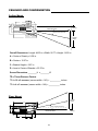
Dimensions . . . . . . . . . . . . . . . . . . . . . . . . . . . . . . . . . . . . . . . . . . . . . . . . . . . . . . . . . . . . . . . . . . . . . 86
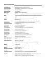
Specifications . . . . . . . . . . . . . . . . . . . . . . . . . . . . . . . . . . . . . . . . . . . . . . . . . . . . . . . . . . . . . . . . . . 87
3
SAFETY INSTRUCTIONS
Safety Instructions
Notice On Safety
This equipment is built in accordance with the requirements of the international safety standards EN60950, UL
1950 and CSA C22.2 No.950, which are the safety standards of information technology equipment including
electrical business equipment.
These safety standards impose important requirements on the use of safety critical components, materials and
isolation, in order to protect the user or operator against risk of electric shock and energy hazard, and having
access to live parts.
Safety standards also impose limits to the internal and external temperature rises, radiation levels, mechanical
stability and strength, enclosure construction and protection against the risk of fire.
Simulated single fault condition testing ensures the safety of the equipment to the user even when the equipment's normal operation fails.
Installation Instructions
Before operating this equipment please read this manual thoroughly, and retain it for future reference.
Installation and preliminary adjustments should be performed by qualified Runco personnel or by authorized
Runco service dealers.
Owner’s Record
The part number and serial number are located at the back side of the projector. Record these numbers in the
spaces provided below. Refer to them whenever you call upon your Runco dealer regarding this product.
SERIAL NUMBER :
DEALER :
Safety Indication On The Product
CAUTION
RISK OF ELECTRIC SHOCK
DO NOT OPEN
!
CAUTION: TO REDUCE THE RISK OF ELECTRIC
SHOCK, DO NOT REMOVE COVER (OR BACK)
NO USER-SERVICEABLE PARTS INSIDE
REFER SERVICING TO QUALIFIED SERVICE
PERSONNEL
The lightning flash with an arrowhead within a triangle is intended to tell the user
that parts inside this product may cause a risk of electrical shock to persons.
!
The exclamation point within a triangle is intended to tell the user that important
operating and/or servicing instructions are included in the technical documentation
for this equipment.
4
Safety Warning
TO PREVENT FIRE OR ELECTRICAL SHOCK HAZARD, DO NOT EXPOSE THIS EQUIPMENT TO RAIN OR
MOISTURE
Federal Communication Commission (FCC Statement)
This equipment has been tested and found to comply with the limits of a class B digital device, pursuant to Part
15 of the FCC Rules. These limits are designed to provide reasonable protection against harmful interference
when the equipment is operated in a commercial environment. This equipment generates, uses and can radiate
radio frequency energy and, if not installed and used in accordance with the instruction manual, may cause
harmful interference to radio communications. Operation of this equipment in a residential area is likely to
cause harmful interference in which case the user will be required to correct the interference at his own
expense.
Note :
The use of shielded cables is required to comply within the limits of Part 15 of FCC rules and EN55022.
• All the safety and operating instructions should be read before using this unit.
• The safety and operating instructions manual should be retained for future reference.
• All warnings on the equipment and in the documentation manuals should be adhered to.
• All instructions for operating and use of this equipment must be followed precisely.
On Safety
1. This product should be operated from an AC power source.
Power input is autoranging from 100 V(-10%) to 240V(+6%).
2. All equipment in the system is equipped with a 3-wire grounding plug, a plug having a third (grounding) pin.
This plug will only fit into a grounding-type power outlet. This is a safety feature. If you are unable to insert the
plug into the outlet, contact your electrician to replace your obsolete outlet. Do not defeat the purpose of the
grounding-type plug.
WARNING FOR THE CUSTOMERS: THIS APPARATUS MUST BE GROUNDED (EARTHED) via the supplied
3 conductor AC power cable. (If the supplied power cable is not the correct one, consult your dealer.)
CEE 7
LINE = BROWN
NEUTRAL = BLUE
GROUND = YELLOW/GREEN
ANSI 73.11
A. Mains lead (Power cord) with CEE 7 plug:
The wires of the mains lead are colored in accordance with the following code.
Green and Yellow:
Blue:
Brown:
earth (safety earth)
neutral
line (live)
B. Power cord with ANSI 73.11 plug:
The wires of the power cord are colored in accordance with the following code.
Green/Yellow:
ground
White:
neutral
Black:
line (live)
LINE = BLACK
NEUTRAL = WHITE
GROUND = YELLOW/GREEN
5
3. Do not allow anything to rest on the power cord. Do not locate this product where persons will walk on the
cord. To disconnect the cord, pull it out by the plug. Never pull the cord itself.
4. If an extension cord is used with this product, make sure that the total of the ampere ratings on the products
plugged into the extension cord does not exceed the extension cord ampere rating.
5. Never push objects of any kind into this product through cabinet slots as they may touch dangerous voltagepoints or short out parts that could result in a risk of fire or electrical shock.
Never spill liquid of any kind on the product. Should any liquid or solid object fall into the cabinet, unplug the set
and have it checked by qualified service personnel before resuming operations.
6. Lightning - For added protection for this video product during a lightning storm, or when it is left unattended
and unused for long periods of time, unplug it from the wall outlet. This will prevent damage to the projector due
to lightning and AC power-line surges.
Caution on Fire Hazard
Do not place flammable or combustible materials near projector !
Runco large screen projection products are designed and manufactured to meet the most stringent safety regulations. This projector radiates heat on its external surfaces and from ventilation ducts during normal operation,
which is both normal and safe.
Exploding, flammable or combustible materials into close proximity of this projector could result in the spontaneous ignition of that material, resulting in a fire. For this reason, it is absolutely necessary to leave an "exclusion zone" around all external surfaces of the projector whereby no flammable or combustible materials are
present. Do not cover the projector with any material while the projector is in operation.
Keep flammable and combustible materials away from the projector at all times. Mount the projector is a well
ventilated area away from sources of ignition and out of direct sun light. Never expose the projector to rain or
excessive moisture. In the event of fire, use sand, CO2, or dry powder fire extinguishers; never use water on an
electrical fire.
Always have service performed on this projector by authorized Runco service personnel. Always insist on genuine Runco replacement parts. Never use non-Runco replacement parts as they may degrade the safety of this
projector.
On Installation
1. Do not place this equipment on an unstable cart, stand, or table. The product may fall, causing serious
damage to it.
2. Do not use this equipment near water.
3. Slots and openings in the cabinet and the back or bottom are provided for ventilation; to ensure reliable operation of the product and to protect it from overheating, these openings must not be blocked or covered. The
openings should never be blocked by placing the product on a bed, sofa, rug, or other similar surface. This
product should never be placed near or over a radiator or heat register.
The projector should not be placed in a built-in installation or enclosure unless proper ventilation is provided.
4. Do not block the projector cooling fans or free air movement under and around the projector. Loose papers or
other objects may not be nearer to the projector than 4" on any side.
6
On Servicing
Do not attempt to service this product yourself, as opening or removing covers may expose you to dangerous
voltage potentials and risk of electric shock!
Refer all servicing to qualified service personnel.
Unplug this product from the wall outlet and refer servicing to qualified service personnel under the following
conditions:
a. When the power cord or plug is damaged or frayed.
b. If liquid has been spilled into the equipment.
c.If the product has been exposed to rain or water.
d. If the product does not operate normally when the operating instructions are followed.
Note: Adjust only those controls that are covered by the operating instructions since improper adjust
ment of the other controls may result in damage and will often require extensive work by a qualified
technician to restore the product to normal operation.
e. If the product has been dropped or the cabinet has been damaged.
f. If the product exhibits a distinct change in performance, indicating a need for service.
Replacement parts - When replacement parts are required, be sure the service technician has used original
Runco replacement parts or authorized replacement parts which have the same characteristics as the Runco
original part. Unauthorized substitutions may result in degraded performance and reliability, fire, electric shock or
other hazards. Unauthorized substitutions may void warranty.
Safety check - Upon completion of any service or repairs to this projector, ask the service technician to perform
safety checks to determine that the product is in proper operating condition.
On Cleaning
Unplug this product from the wall outlet before cleaning. Do not use liquid cleaners or aerosol cleaners. Use a
damp cloth for cleaning.
- To keep the cabinet looking brand-new, periodically clean it with a soft cloth. Stubborn stains may be removed
with a cloth lightly dampened with mild detergent solution. Never use strong solvents, such as thinner or benzine, or abrasive cleaners, since these will damage the cabinet.
- To ensure the highest optical performance and resolution, the projection lenses are specially treated with an
anti-reflective coating, therefore, avoid touching the lens. To remove dust on the lens, use a soft dry cloth.
On Repacking
Save the original shipping carton and packing material; they will come in handy if you ever have to ship your
equipment. For maximum protection, repack your set as it was originally packed at the factory.
On Illumination
In order to obtain the best quality for the projected image, it is essential that the ambient light which is allowed to
fall on the screen be kept to an absolute minimum. When installing the projector and screen, care must be taken
to avoid exposure to ambient light directly on the screen. Avoid adverse illumination on the screen from direct
sunlight or fluorescent lighting fixtures. The use of controlled ambient lighting, such as incandescent spot light or
a dimmer, is recommended for proper room illumination. Where possible, care should also be taken to ensure
that the floors and walls of the room in which the projector is to be installed are non-reflecting, dark surfaces.
Brighter surfaces will tend to reflect and diffuse the ambient light and hence reduce the contrast of the projected
image on the screen.
7
Limited Warranty
LIMITED WARRANTY
Congratulations on your purchase of a Runco video product and welcome to the Runco family! We
believe Runco produces “The World’s Finest Home Theater Products”. With proper installation, setup
and care, you should enjoy many years of unparalleled video performance. Please read this consumer
protection plan carefully and retain it with your other important documents.
This is a LIMITED WARRANTY as defined by the U.S. Consumer Product Warranty and Federal Trade
Commission Improvement Act.
WHAT IS COVERED UNDER THE TERMS OF THIS WARRANTY:
SERVICE LABOR: Runco will pay for service labor by an approved Runco service center when needed as a result of manufacturing defect for a period of two (2) years from the effective date of delivery to
the end user.
PARTS (Not including projector lamp): Runco will provide new or rebuilt replacement parts for the parts
that fail due to defects in materials or workmanship for a period of two (2) years from the effective date
of the warranty. Such replacement parts are then subsequently warranted for the remaining portion (if
any) of the original warranty period.
LAMP: Six months or 1000 hours (which ever comes first).
WHAT IS NOT COVERED UNDER THE TERMS OF THIS WARRANTY:
This warranty only covers failure due to defects in materials and workmanship that occur during normal
use and does not cover normal maintenance. This warranty does not cover cabinets or any appearance
item; any damage to laser discs; failure resulting from accident, misuse, abuse, neglect, mishandling,
misapplication, faulty or improper installation or setup adjustments; improper maintenance, alteration,
improper use of any input signal; damage due to lightning or power line surges, spikes and brownouts;
damage that occurs during shipping or transit; or damage that is attributed to acts of God. In the case
of remote control units, damage resulting from leaking, old, damaged or improper batteries is also
excluded from coverage under this warranty.
CAUTION: DAMAGE RESULTING DIRECTLY OR INDIRECTLY FROM IMPROPER INSTALLATION
OR SETUP IS SPECIFICALLY EXCLUDED FROM COVERAGE UNDER THIS WARRANTY. IT IS
IMPERATIVE THAT INSTALLATION AND SETUP WORK BE PERFORMED ONLY BY AN AUTHORIZED RUNCO DEALER TO PROTECT YOUR RIGHTS UNDER THIS WARRANTY. THIS WILL ALSO
ENSURE THAT YOU ENJOY THE FINE PERFORMANCE YOUR RUNCO PRODUCT IS CAPABLE OF
PROVIDING WHEN INSTALLED AND CALIBRATED BY RUNCO AUTHORIZED PERSONNEL.
RIGHTS, LIMITS AND EXCLUSIONS:
Runco limits its obligations under any implied warranties under state laws to a period not to exceed the
warranty period. There are no express warranties. Runco also excludes any obligation on its part for
incidental or consequential damages related to the failure of this product to function properly. Some
states do not allow limitations on how long an implied warranty lasts, and some states do not allow the
exclusion or limitation of incidental or consequential damages. So the above limitations or exclusions
may not apply to you. This warranty gives you specific legal rights, and you may also have other rights
that vary from state to state.
8
EFFECTIVE WARRANTY DATE:
This warranty begins on the effective date of delivery to the end user. For your convenience, keep the
original bill of sale as evidence of the purchase date.
IMPORTANT: WARRANTY REGISTRATION:
Please fill out and mail your warranty registration card. It is imperative that Runco knows how to reach
you promptly if we should discover a safety problem or product update for which you must be notified.
TO OBTAIN SERVICE, CONTACT YOUR RUNCO DEALER:
Repairs made under the terms of the Limited Warranty covering your Runco International video product
will be performed at the location of the product, during usual working hours, providing location of product is within normal operating distance from a Runco Authorized Service Center. If, solely in Runco’s
judgement, location of product to be repaired is beyond normal operating distance of the closest Runco
Authorized Service Center, it is the owner’s responsibility to arrange for shipment of the product for
repair. These arrangements must be made through the selling Runco dealer. If this is not possible, contact Runco directly for a return authorization number and shipping instructions. Runco will return product transportation prepaid in the United States, unless no product defect is discovered. In that instance,
shipping costs will be the responsibility of the owner.
ADDITIONAL INFORMATION:
To locate the name and address of the nearest Runco Authorized Service location, or for additional information about this warranty, please call, write or visit our website:
CUSTOMER SERVICE DEPARTMENT
RUNCO INTERNATIONAL
2900 Faber Street
Union City, CA 94587
Ph: (510) 324-7777 / Fax: (510) 324-9300
www.runco.com
9
CONNECTIONS
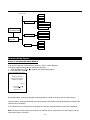
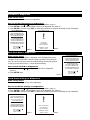
Power Connection to Projector
AC Power (Mains) Cord Connection
Use the supplied power cord to connect your Projector to the wall outlet. Plug the female power connector into
the male connector at the rear side of the Projector.
AC Input
OFF/ON
75 Ohm
R
G
B
H
V
S-Video
OFF/ON
75 Ohm
Video
12 Volt
Trigger
Green: Operation
Red: Standby
Status
OFF ON
INPUT 4/5
Future Expansion
INPUT 2
INPUT 1
AC Input
OFF ON
Power Check
The power voltage is autoranging between 100V(-10%) and 240V (+6%).
Switching On/Off
The Projector is switched ON and OFF using the power (mains) switch ON/OFF.
Pushed In: ON
Out: OFF
The Projector can start in the operational mode (ON) or in the stand by mode, depending on the power up setting in the service mode.
Stand by indication lamp :
OFF: Projector switched OFF
Green: Projector is ON
Red: Projector is in Standby Mode.
OFF/ON
75 Ohm
Video
12 Volt
Trigger
Green: Operation
Red: Standby
Status
INPUT 1
When turning ON the Projector, it can start up in two ways if the "CRT run in" cycle option is switched OFF.
- full white image (projector warm up) or
- immediate image display.
This option can be enabled in the service mode (see page 72).
10
Source Connections
Input Facilities
The following source types can be connected to the inputs :
•
•
•
•
RGB Tri-level Sync
RGB Composite, Separate or Sync on green
Component Video
Component Video with Tri-level Sync
AC Input
OFF/ON
75 Ohm
R
G
B
H
V
S-Video
OFF/ON
75 Ohm
Video
12 Volt
Trigger
OFF ON
INPUT 4/5
Future Expansion
3
4
INPUT 2
5
2
Which source to which input
Source No.
Projector Input
Remote Button No.
1
Comp. Video*
1 (not used)
2
S-Video/Comp. Video*
2 (not used)
3
RGB
3
4/5
RGB
4 or 5
4/5
Component Video
6
4/5
RGB with Tri-level Sync
7
4/5
Component Video
with Tri-level Sync
8
* Not used in the DTV-1200
11
INPUT 1
1
Green: Operation
Red: Standby
Status
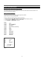
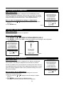
RGB Source to Input 3
Which signal to Input 3
Connect your RGB source with sync on green, composite or separate sync via an interface to Input 3.
Always use an interface when a computer and local monitor have to be connected to the projector as the signal
cable coming from the computer is limited to 60 cm due to interferences.
Pin configuration D9 connector of the Analog input.
1
Not connected
2
Ground RGBS
3
RED
4
GREEN
5
BLUE
6
Ground RGBS
7
Ground RGBS
8
Hor/comp. sync
9
Vert. sync
AC Input
OFF/ON
75 Ohm
R
G
B
H
V
S-Video
OFF/ON
75 Ohm
Video
Green: Operation
Red: Standby
12 Volt
Trigger
Status
OFF ON
INPUT 4/5
Future Expansion
ON
ANALOG INTERF. 120MHz
INPUT
B
H
INPUT 2
INPUT 1
V
OFF
R
G
INP
75 ohm term.
INP
inver.
Input Select Input 3
With the Remote, press button 3
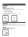
RGB Source with Composite Sync to Input 4/5
Which signal to Input 4/5
RGB input terminals with separate H and V Sync inputs, Composite Sync Input or with Sync on green (BNC terminals). The Projector detects automatically where the sync signal is located. This is the Input where Video
Processors (such as the Runco VHD-4404 Ultra) or high definition sources should be connected.
AC Input
OFF/ON
75 Ohm
R
G
B
H
V
OFF/ON
75 Ohm
Video
S-Video
12 Volt
Trigger
OFF ON
Future Expansion
INPUT 2
INPUT 4/5
INPUT 1
Menu
4404 ULTRA
RUNCO
M U LT I F I L M
RGB Sync on green or separate Sync Input selection
With the remote, press:
- Button 4 for Sync on green
- Button 5 for Separate Sync
12
Green: Operation
Red: Standby
Status
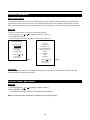
RGB Source with Tri-level Sync to Input 4/5
Which signal to Input 4/5
RGB input terminals with Tri level sync input or with Tri-level sync on green (BNC terminals). The projector
detects automatically where the sync signal is located.
RGB3S or RG3sB input selection
With the remote, press digit button 7
Component Source to Input 4/5
Which signal to Input 4/5
(R-Y)Y(B-Y) input terminals with sync input or with sync on the luminance (Y) input (BNC terminals). The projector detects automatically where the sync signal is located.
Component Video input selection
With the remote, press digit button 6
RS-232 Connection
RS-232 input and RS-232 output of the Projector.
The projector is equipped with a RS-232 port that allows communication with an automation system such as
AMX, Crestron, etc.
Applications
a) remote control:
- allow storage of multiple projector configurations and set ups.
- wide range of control possibilities.
- address range from 0 to 255.
b) data communications:
- sending data to the projector or copying the data from the projector to a hard memory device.
Set up of the Baud Rate for Communication with a Computer.
See 'Changing the Baud Rate' in chapter 'Service Mode'.
13
GETTING STARTED
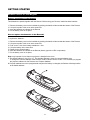
Remote Control & Local Keypad
Battery Installation in the Remote
Two batteries are packed together with the Remote. Before using your Remote, install first these batteries.
1
2
3
4
Remove the battery cover on the backside by pushing the handle a little towards the bottom of the Remote.
Lift up the top side of the cover at the same time.
Insert the batteries as indicated in the Remote.
Put the battery cover on its place.
How to replace the batteries in the Remote?
To replace the batteries :
1
2
3
4
5
6
7
Remove the battery cover on the backside by pushing the handle a little towards the bottom of the Remote.
Lift up the top side of the cover at the same time.
Push on the + side of the battery towards the - side
Lift up the battery at the same time.
Repeat for the second battery.
Insert the batteries as indicated in the Remote (battery type AA or LR6 or equivalent).
Put the battery cover on its place.
Note: only important if more than one projector is installed in the room :
1. The default address is zero (0) or (1). The standard Remote is setup for common address zero.
To change the common address of the Remote, contact a Runco service center. If it is necessary to program
the projector address into the Remote, see 'Projector Address'.
2. Projector address has to be reprogrammed everytime the battery is changed, the Remote will always switch
to the default address.
14
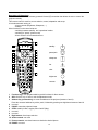
Overview of Functions
This remote control includes a battery powered infrared (IR) transmitter that allows the user to control the
projector remotely.
This remote control is used for source selection, control, adaptation and set-up.
It includes automatic storing of:
- picture controls (Brightness, Sharpness,....)
- settings
Other functions on the control units are:
- switching between standby and operational modes
- switching to "pause" (picture mute)
- direct access to all connected sources
18
1
2
F3
F2
F4
standby
F5
F1
ADJ
EXIT
3
17
16
4
ENTER
5
6
PAUSE
TEXT
7
8
9
0
9
7
8
TINT
5
6
COLOR
3
4
BRIGHTN
1
2
CONTR
PHASE
15
14
pause/park
sharpness
13
12
tint
SHARPN
color
11
brightness
contrast
10
TREBLE
BASS
BALANCE
VOL
1
2
3
Function keys: user programmable keys with functions for direct access.
ADJ: ADJUST key, to enter or exit the adjustment mode.
Address key (recessed key): to enter the address of the projector (between 0 and 9).
Press the recessed address key with a pencil, followed by pressing one digit button between 0 and 9.
4 not used
5 PAUSE: mutes the projected image.
6 STBY: stand-by button, toggles power On/Off (Stby).
7 not used
8 not used
9 Digit buttons: direct input selection.
10 Audio controls: not used
11 Picture controls: use these buttons to obtain the desired picture.
12 PHASE: not used.
15
13 FREEZ: press to freeze the projected image.
14 TEXT: when adjusting one of the image controls, e.g. contrast, during a meeting, the displayed bar scale
can be removed by pressing 'TEXT' key first. To re-display the bar scale on the screen, press 'TEXT' key again.
15 ENTER: to start up the adjustment mode or to confirm an adjustment or selection in the adjustment mode.
16 Cursor Keys: to make menu selections when in the adjustment mode.or to increase or decrease the analog
level of the image controls when they are first selected.
17 EXIT: to leave the adjustment mode or to scroll upwards when in the adjustment mode.
18 IR Output LED: lights up when a button on the remote control is pressed. (This is a visual indicator to
check the operation of the remote control)
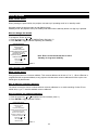
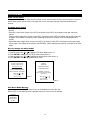
Start Up
Press the Power button on the remote; ensure the main Power button on the rear of the Projector is pressed in.
When this warm up cycle message appears on the screen, the menu offers the possiblity to start with a warm
up period (press ENTER) or to skip this cycle (press EXIT). The number of minutes and the horizontal frequecy
can be programmed in the 'Service mode' under the item 'Projector Set Up'.
Note: This warm up period is built in so that the Projector can quickly reach its operating temperature.
When starting this warm up period, a full white image is shifted on the CRT faceplate to avoid a burn in. Every
30 seconds a text box will be displayed on another place on the screen with the remaining time to go.
The image dimensions can be adjusted with the cursor keys to avoid scanning on the edges of the CRT's.
PROJECTOR WARM UP
A FULL WHITE PATTERN WILL BE
GENERATED FOR x MIN.
FOR IMMEDIATE USE OF THE
PROJCTOR, PRESS <EXIT>
WARNING : SKIPPING THIS
PROCEDURE CAN REDUCE THE
INITIAL PICTURE QUALITY OF THE
PROJECTED IMAGE;
YOU CAN ADJUST THE IMAGE
DIMENSTIONS WITH THE ARROW
KEYS TO AVOID SCANNING ON THE
EDGES OF THE CRT'S;
THIS OPTION CAN BE DISABLED IN
THE SERVICE MENU
with <ENTER>
<EXIT> to return
To interrupt the warm up period:
1 Press EXIT, the warm up menu will be redisplayed with the remaining time indication.
2 Press EXIT again to quit the warm up cycle and to display the source.
Start Up in a Specific Source
When the Projector is in Standby, it can be turned ON with a specific source. To do this, simply press the source
number button (see page 19).
Stationary Image Warning
!
Do not display a stationary image with full brightness and contrast for longer than 10
minutes, otherwise you risk damage to the CRT's.
16
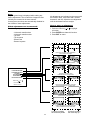
Remote Commands to the Projector
Pointing the Remote to the reflective screen
Point the front of the Remote to the screen surface.
Ceiling
IR sensor
Screen
Remote
Point the front of the Remote towards one of the IR sensors in the projector.
Rear side of projector
Front of projector
See installation instructions before connecting to the supply.
Voir la notice d'installation avant de raccorder au réseau.
V-nom
I-nom
OFF
ON
Freq
POWER / MAINS
F3
F2
COMM. PORT
PORT 3
G
B
Comp-/H-Sync
V-Sync
F3
F2
F5
ADJ
OFF - ON
75 Ohm
PORT 2
TEXT
PHASE
PAUSE
Remote
TEXT
PHASE
0
9
0
8
TINT
7
8
TINT
5
6
COLOR
5
6
COLOR
3
4
BRIGHTN
3
4
BRIGHTN
1
2
CONTR
1
2
CONTR
BASS
BALANCE
VOL
15
EXIT
7
TREBLE
red : standby
PROJECTOR MODE
ENTER
9
SHARPN
green : operation
75 Ohm
F5
ADJ
ENTER
PAUSE
OFF - ON
PORT 1
F4
F1
EXIT
VIDEO
45°
F4
F1
" This devicecomplies with Part
of
Operationis subject to
following two conditions: (1) This
device may not cause harmful interference, and (2) this device must
accept any interference received,
including interferencethat may cause
undesired operation"
the FCC
Rules.
S-VIDEO
PORT 4/5
45°
45°
45°
R
800 peripherals
120/230
V
7/5 Amp
50/60
Hz
TREBLE
BASS
SHARPN
BALANCE
VOL
When using the wireless remote control, make sure you are within the effective operating distance (30m, 100ft
in a straight line). The remote control unit will not function properly if strong light strikes the sensor window or if
there are obstacles between the remote control unit and the projector's IR sensor.
Remote used in a hardwired configuration.
RS232 INRS232 OUT IR REMOTE
Plug one end of the remote cable in the
connector on the bottom of the Remote and
the second side in the connector in the rear
panel of the projector labelled 'REMOTE'.
17
REMOTE IR RS232 OUT RS232 IN
Projector Address
Why a projector address?
Since more than one projector can be installed in a room, the separate projectors can be separately addressable with a Remote or a computer.
Set up an Individual Projector Address
The set up of a projector address can be done via the software.
See 'Change Projector Address' in Chapter 'Service Mode'
How to control the projector or projectors?
The projector's address may be set to any value between 0 and 255 which can be set in the Service Mode.
When the address is set, the projector can be controlled now with:
- the Remote for addresses between 0 and 9.
- a Control System for addresses between 0 and 255.
Note: A projector will respond to a Remote set to the common address ('0' or '1') regardless of what address is
set in the projector itself.
Common Address
Every projector has a common address '0' or '1'. The choice between '0' and '1' can be selected in the Service
mode.
Before using the Remote
The Remote is default programmed with address 0 or 1, 'common address'. With that 'common address' programmed into the Remote, every projector, with the same common address set up, will listen to the commands
given by this Remote. If it is necessary to control a specific projector, than enter the projector address into the
Remote (only when that address is between 0 and 9). The projector with the corresponding address will listen to
that specific Remote.
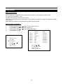
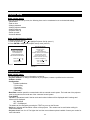
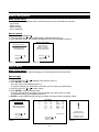
Display the Projector Address on the Screen.
Press the ADDRESS key (recessed key on the Remote) with a pencil. The projector's address will be displayed
in a 'Text box' (menu 1). This text box disappears after a few seconds.
PROJECTOR ADDRESS
001
To continue using the Remote with that specific address, it is necessary to enter the same address with the digit
buttons (address between 0 and 9) within 5 seconds after pushing the address key. For example: if the Address
key displays projector address 003, then press "3" digit button on the Remote to set the Remote's address to
match the projector's address. Do not press 003 digits. This will address the remote control to '0' and control all
projectors in the room.
If the address is not entered within 5 seconds, the Remote returns to its default address (zero address) and
control all projectors in the room.
How to program an address into the Remote?
Press the ADDRESS key (recessed key on the Remote) with a pencil and enter the address with the digit buttons within 5 seconds after pushing the address key. That address can be any digit between 0 and 9.
18
Input selection modes
Source No.
Projector Input
Remote Button No.
3
RGB
3
4/5
RGB (HV, S.O.G)
4 or 5
4/5
Component Video
6
4/5
RGB with Tri level sync
7
4/5
Component Video with
Tri-level sync
8
Input Selection via the Remote.
With the digit buttons, it is possible to select one of the above input modes.
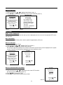
When the source is selected
When a valid and available source is selected, there will be information displayed on the screen about that
source. This information includes:
- Source number
- Horizontal frequency
- Vertical frequency
Source 02
Fh= 63 kHz
Fv= 60 Hz
When the entry is a non valid source number, a warning appears on the screen: 'input not available'.
WARNING
Input not
available
When a valid source number is selected, the projector will display this source or it will wait on the selected
source number until the source becomes available. A message 'source not available' will be displayed for a
short time.
WARNING
Source not
available
When a Video or S-Video source is selected and no decoder is installed, the projector displays the folllowing
message: 'Option not installed'.
WARNING
Option not
installed!
19
Picture Controls
The control keys are located on the right side of the key panel of the Remote and indicated with the name of the
control and an icon.
When an image control is pressed, a text box with bar scale and the function name of the control, e.g. 'brightness...' appears on the screen (only if text is ON). The length of the bar scale indicates the current memorized
setting for this source. The bar scale changes as the + or - side of the button of the control are pressed.
Brightness Control:
A correct 'brightness' setting is important for good image reproduction. Adjust the brightness with the + button
and - button until the darkest parts of the picture appear black.
A bar scale gives a visual indication on the screen of the current brightness setting while pressing on the above
indicated buttons. If the bar scale is not visible on the screen, press 'TEXT' once and retry the above indicated
buttons.
The bar scale increases when pressing on the + button (higher brightness) and decreases when pressing on the
- button (lower brightness).
Contrast Control:
A correct 'contrast' setting is important for good image reproduction.
Adjust the contrast to the level you prefer, according to room lighting conditions.
A bar scale gives a visual indication on the screen of the current contrast setting while pressing the + or - buttons . If the bar scale is not visible on the screen, press 'TEXT' key once and retry the above indicated buttons.
The bar scale increases when pressing on the + button (higher contrast) and decreases when pressing on the button (lower contrast).
Color Saturation Control: Not used on the DTV-1200
Tint Control: Not used on the DTV-1200
Sharpness Control: Not used on the DTV-1200
Sound Controls: Not used on the DTV-1200
The Pause Key
The ‘Pause’ button mutes the projected image. When Pause is pressed, the image will disappear until it is
pressed again.
The Freeze Key
When the Freeze key is pressed, the image is frozen until this key is pressed again.
20
START UP OF THE ADJUSTMENT MODE
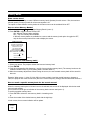
Adjustment Mode
Start Up
All picture adjustments are made while in the 'Adjustment mode'.
Press the ADJUST key.
The projector displays the 'Main menu' (menu 1).
MAIN MENU
Image Control
Eye-Q
Function Keys
Service Menus
Select with
or
then <ENTER>
<EXIT> to return
menu 1
You are now in the 'Adjustment mode'. The cursor keys are used to make menu selections and also vertical and
horizontal adjustments. The ENTER and EXIT keys are used to move forward and backward through the menu
structure. The ADJUST key can be used to terminate the adjustment mode while a path selection menu (head
menu) is displayed.
Possible Paths
Depending on the projector configuration the following paths are possible with the 'Main menu'.
Image Control - Allows you to change the color temperature of the image and to select another format (adjustment) for the image.
Eye-Q Control - This control allows to align the projector automatically using the autoconvergence unit EYE-Q
built into the projector.
Function Keys - Gives an overview of the programmed function for each key.
Service Menus - Installation and adjustment menus to set up the projector. Before entering a warning will be
displayed.
21
MAIN MENU
Main Menu
Overview Flowchart
COLOR ADJUST
IMAGE CONTROL
FORMAT SELECT
EYE-Q TOUCH UP
EYE-Q CONTROL
EYE-Q AUTO CONVERGE
EYE-Q FULL ALIGNMENT
MAIN MENU
F1
F2
FUNCTION KEYS
F3
F4
F5
EYE-Q
GUIDED
SERVICE MENUS
RANDOM ACCESS
INSTALLATION
SERVICE
22
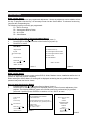
Image Control
Starting Up
1
2
Push the cursor keys é or ê to select 'Image Control' (menu 1).
The selected item will change in color and a marker will be displayed in front of it.
Press ENTER to select.
The 'Image Control' menu will be displayed (menu 2a).
MAIN MENU
IMAGE CONTROL
Image Control
Image Processing
Eye-Q
Color Adjust
Function Keys
Format Select
Service Menus
Select with
or
then <ENTER>
Select with
<EXIT> to return
or
then <ENTER>
<EXIT> to return
menu 1
menu 2a
Color Adjust
What can be done?
The color temperature of the image can be installed. The customer has the choise between 4 factory preset
color temperatures and one custom. This custom color temperature has to be adjusted in the 'Random Access
Adjustment Mode'.
How to select 'Color Adjust' and to select a new color temperature?
1
Push the cursor keys
or
to select 'Color Adjust' (menu 1).
2
Press ENTER to display the Color Adjust menu (menu 2).
3
Push the cursor keys
or
to select the desired color temperature.
4
Press ENTER to activate that color temperature.
COLOR ADJUST
o
3200 K
o
4900 K
o
6500 K
o
9300 K
Broadcast
IMAGE CONTROL
Film
Video
Image Processing
Color Adjust
Computer
Format Select
Custom
Select with
menu 1
Select with
or
or
then <ENTER>
then <ENTER>
<EXIT> to return
<EXIT> to return
menu 2
23
Format Select
What can be done?
For one source, up to 8 different sets of settings can be stored. A set of settings is called 'Format'.
A 'Format' can be 'available' or 'free'.
'Available' when settings are stored in this location.
'Free' when no setting are stored in this location. This location can be used for storing new adjustment settings
for this source.
When 'available', a name of 8 characters can be programmed by the user.
How to select a 'Format' ?
1
2
3
4
Push the cursor keys
or
to select 'Format Select' (menu 1).
Press ENTER to display the Format List (menu 2).
Push the cursor keys
or
to select the desired ‘Format’.
Press ENTER to select.
FORMAT LIST
Source 01
IMAGE CONTROL
Image Processing
Color Adjust
Format Select
Select with
VIDEO
Format 1
Available
xxxxxxxxxx
Format 2
Free
xxxxxxxxxx
Format 3
Available
xxxxxxxxxx
Format 4
Free
xxxxxxxxxx
Format 5
Free
xxxxxxxxxx
Format 6
Free
xxxxxxxxxx
Format 7
Free
xxxxxxxxxx
Format 8
Free
xxxxxxxxxx
or
then <ENTER>
Select with
<EXIT> to return
or
then <ENTER> to select
<EXIT> to return
menu 1
<TEXT> to enter a name
menu 2
24
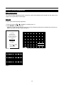
How to add a name to a 'Format'?
1
2
3
Push the cursor keys
or
to select the Format to which a name has to be added (menu 1).
Press TEXT to display the compose menu (menu 2).
The position of the character which will be edited, will be indicated with a digit. Push the cursor keys
,
,
or
to select the first character.
Press ENTER to select the choosen character. This character will be inserted on the indicated position.
The 'edit character' indication will be incremented with one.
Continue in the same way for the other characters.
When the name is completed, press EXIT to return to the 'Format List' menu (menu 3).
4
5
6
FORMAT LIST
COMPOSE
Source 01
VIDEO
Available
xxxxxxxxxx
Format 2
Free
xxxxxxxxxx
Format 3
Available
xxxxxxxxxx
Format 4
Free
xxxxxxxxxx
Format 5
Free
xxxxxxxxxx
Format 6
Free
xxxxxxxxxx
Format 7
Free
xxxxxxxxxx
Format 8
Free
xxxxxxxxxx
Format 1
Select with
A
J
S
/
0
B C D
K L M
T U V
:
1 2 3
5
6
Edit character 1
Select with
or
then <ENTER>
then <ENTER> to select
<EXIT> to return
<EXIT> to return
<TEXT> to enter a name
menu 1
menu 2
FORMAT LIST
VIDEO
Format 1
Available
xxxxxxxxxx
Format 2
Free
xxxxxxxxxx
Format 3
Available
xxxxxxxxxx
Format 4
Free
xxxxxxxxxx
Format 5
Free
xxxxxxxxxx
Format 6
Free
xxxxxxxxxx
Format 7
Free
xxxxxxxxxx
Format 8
Free
xxxxxxxxxx
Select with
4
XXXXXXXXXX
or
Source 01
E F G H
N O P Q
W X Y Z
or
then <ENTER> to select
<EXIT> to return
<TEXT> to enter a name
menu 3
25
7
I
R
8
9
How to store the settings to a new 'Format'?
1
2
3
4
Push the cursor keys
or to select a free format.
Press ENTER to activate.
Make any adjustment to the image.
Quit the adjustment mode by pressing ADJUST.
The selected format will change from free to available.
Eye-Q Control
With the Eye-Q functions it is possible to automatically adjust the convergence of the image.
Start Up
1
2
Push the cursor keys
or to select 'EYE-Q control' (menu 1).
The selected item will change in color and a marker will be displayed in front of it.
Press ENTER to select.
The 'EYE-Q control' menu will be displayed (menu 2).
MAIN MENU
EYE-Q CONTROL
Image Control
EYE-Q Touch Up
Eye-Q
EYE-Q Auto Converge
Function Keys
Service Menus
Select with
Select with
or
or
then <ENTER>
then <ENTER>
<EXIT> to return
<EXIT> to return
menu 1
menu 2
Note: Before starting one of the EYE-Q functions, be sure the projector has warmed up for at least 20 min.
Eye-Q Touch Up
What can be done?
If you discover in the middle of the image a convergence misalignment between red, green and blue, the static
convergence of this currently selected source can be adjusted with the touch up function.
26
How to start up the EYE-Q Touch Up?
1
2
Push the cursor keys
or
to select 'EYE-Q Touch Up' (menu 1).
Press ENTER to activate the touch up function.
The process starts and when successfully completed, the projector will return to image display of the
current source.
EYE-Q CONTROL
EYE-Q Touch Up
EYE-Q Auto Converge
Select with
or
then <ENTER>
<EXIT> to return
menu 1
Eye-Q Auto Converge
What can be done?
The autoconvergence on the current source will be carried out automatically, starting from the existing settings.
By projecting alternately red and blue lines, 25 convergence areas are aligned onto the green pattern.
How to start up the EYE-Q Auto Converge?
1
2
Push the cursor keys
or
to select 'EYE-Q Auto Converge' (menu 1).
Press ENTER to activate the autoconvergence function.
The process starts and when successfully completed, the projector will return to image display of the
current source.
EYE-Q CONTROL
EYE-Q Touch Up
EYE-Q Auto Converge
Select with
or
then <ENTER>
<EXIT> to return
menu 1
27
Function Keys
What can be done?
Quick access keys to customer pre-programmed adjustments. Almost any adjustment can be added to a function key. To program a function key, it is necessary to enter into the 'Service Menu'. To activate a function key,
just press the corresponding key.
The following functions are factory pre-programmed :
F1 = EYE-Q Touch up
F2 = Convergence Red on Green
F3 = Convergence Blue on Green
F4 = H & V Size
F5 = Color Balance
How to get an overview of the programmed keys?
1
Push the cursor keys
or
to select 'Function Keys' (menu 1).
2
Press ENTER to display an overview of the function keys (menu 2).
3
Press EXIT to return.
MAIN MENU
FUNCTION KEYS
Image Control
F1: EYE-Q Touch Up
Eye-Q
F2: Convergence Red on Green
Function Keys
F3: Convergence Blue on Green
F4: H & V Size
Service Menus
Select with
F5: Color Balance
or
then <ENTER>
<EXIT> to return
<EXIT> to return
menu 1
menu 2
Service Menus
What can be done?
With the complete set of Service menus such as EYE-Q, Guide, Random Access, Installation and Service it is
possible to adjust the projector completely.
When entering the Service Menus, a warning will be displayed mentioning that only qualified Runco service
personnel may enter the Service menus.
How to enter the Service Menu?
1
Push the cursor keys
or
to select 'Service Menus' (menu 1).
2
Press ENTER to select. A warning will be displayed (menu 2). "Risk of incorrect adjustment of the
projector. The following SERVICE menus are reserved to and to be performed only by qualified
personnel! If qualified, press <ENTER> to continue, or if not, <EXIT> to return.
MAIN MENU
WARNING
RISK OF INCORRECT ADJUSTMENT
OF THE PROJECTOR.
Image Control
Eye-Q
Select a path from below:
EYE-Q
The following SERVICE menus are reserved to,
and to be performed only by qualified personnel !
Function Keys
Service Menus
Select with
ADJUSTMENT MODE
or
RANDOM ACCESS
INSTALLATION
If qualified, press
<ENTER> to continue, or
if not, <EXIT> to return.
SERVICE
Source 1
then <ENTER>
<EXIT> to return
GUIDED
Select with
menu 2
or
then <ENTER>
<EXIT> to return
menu 1
28
menu 3
ENTERING THE SERVICE MENUS
Service Menus
What is available in the Service menus?
A complete set of adjustments divided in different modes are available to adjust the projector
The different mode are:
EYE-Q: to autoconverge the projector.
Guided : Guided should be selected if the user intends to perform a complete alignment of the projected image
and is not extensively familiar with the projector. All the necessary geometry and convergence adjustments are
executed in a predetermined sequence.
Random Access: Random Access should be selected if the user intends to make only a few adjustments or if
the user is highly qualified and knows the sequence of adjustments.
Installation: Installation should be selected if the projector has been relocated and/or a different screen size is
desired.
Service: Service should be selected if the user intends to change predefined settings.
How to enter the Service Menus?
1
Press the ADJUST key.
The projector displays the 'Main menu' (menu 1).
2
Push the cursor keys
3
Press ENTER to select.
A warning will be displayed (menu 2).
4
If qualified, press ENTER to continue
The Service menus main menu will be displayed (menu 3).
or
to select 'Service Menus'
MAIN MENU
WARNING
RISK OF INCORRECT ADJUSTMENT
OF THE PROJECTOR.
Image Control
Eye-Q
Select a path from below:
EYE-Q
The following SERVICE menus are reserved to,
and to be performed only by qualified personnel !
Function Keys
Service Menus
Select with
ADJUSTMENT MODE
or
GUIDED
RANDOM ACCESS
INSTALLATION
If qualified, press
<ENTER> to continue, or
if not, <EXIT> to return.
SERVICE
Source 1
then <ENTER>
<EXIT> to return
Select with
menu 2
or
then <ENTER>
<EXIT> to return
menu 1
menu 3
29
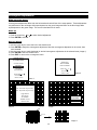
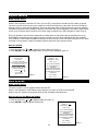
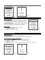
Password Protection
Some items in the Adjustment mode are password protected. While selecting such an item, the projector asks
to enter your password. (Password protection is only available when the password strap on the contoller module
is ON. Contact an authorized Runco technician when no password is requested during the adjustment procedure and password protection is desired.)
enter
password
xxxx
Entering the Password
Your password contains 4 digits.
Enter the digits with the numeric keys on the Remote.
Example : 1 1 1 1
For each digit entered, a 'X' appears on the screen under the displayed text 'enter password'.
When the password is correct, you gain access to the selected item.
When the entered password is wrong, the error message 'wrong password !!!' will be displayed.
Note:
When the password is correctly entered, all other password protected items are accessible without re-entering
the password.
When re-entering the adjustment mode, it will be necessary to enter your password again when selecting a
password protected item.
30
RANDOM ACCESS ADJUSTMENT MODE
Random Access Adjustment Mode
Starting Up
Push the cursor keys up or down to highlight "RANDOM ACCESS" and then press ENTER.
Some items in the Random access mode are password protected (when the password function is enabled).
Enter your password to continue. All other password protected items are now also available if you stay in the
adjustment mode.
ADJUSTMENT MODE
Select a path from below:
EYE-Q
GUIDED
RANDOM ACCESS
INSTALLATION
SERVICE
Source 1
Select with
or
then <ENTER>
<EXIT> to return
Overview Flowchart
COLOR BALANCE
SYNC
PICTURE TUNING
PEAKING
CLAMP TUNING
V CENTERLINE BOW
V CENTERLINE SKEW
RANDOM ACCESS
ADJUSTMENT MODE
H PHASE
SIDE BOW
RASTER SHIFT
SIDE KEYSTONE
LEFT-RIGHT (E-W)
SEAGULL CORRECTION
LEFT KEYSTONE
SETUP PATTERN
SELECTION
LEFT SIDE CORRECTIONS
LEFT BOW
GEOMETRY
H CENTERLINE BOW
H CENTERLINE SKEW
TOP-BOTTOM (N-S)
TOP KEYSTONE
TOP BOW
BOTTOM KEYSTONE
SIZE
SEAGULL CORRECTION
VER LINEARITY
TOP
BOTTOM
LEFT
BLANKING
RIGHT
next page
31
previous page
RED
GREEN
BLUE
COLOR SELECT
RED AND GREEN
BLUE AND GREEN
RED AND BLUE
RANDOM ACCESS
ADJUSTMENT MODE
GREEN ONLY
CONVERGENCE
RED ON GREEN
BLUE ON GREEN
SETUP PATTERN
SELECTION
RED
FOCUSING
GREEN
BLUE
Selecting Setup Pattern
Set up of the Selected Setup Pattern
If an external source is connected to the projector, menu 1 will be displayed.
To select the desired setup pattern, perform the following:
1 Push the cursor keys
or
to highlight the desired setup pattern
2 Press ENTER to select.
Choose a setup pattern from below:
SELECTED SOURCE
GENLOCKED PATTERN
INTERNAL # PATTERN
Source 01
Select with
or
then <ENTER>
<EXIT> to return
menu 1
Genlocked pattern: internally generated cross hatch pattern, locked on the scan rate of external source.
Internal # pattern: internally generated cross hatch pattern and locked on internal generated sync signals. (No
external source necessary)
If no external source is connected to the projector, the internal cross hatch pattern menu will be displayed.
Note: The menus in this manual are created for an external source, connected to one of the inputs, and the
'Genlocked Pattern' is selected.
32
Internal Cross Hatch Pattern
When Using The Internal Cross Hatch Pattern
The Internal # pattern menu will be displayed if the internal cross hatch pattern has been selected or if no
source is connected to the projector.
Factory Preset Frequencies
The table below lists the 14 fixed factory preset frequencies available.
Another 8 blocks are custom programmable.
To
1
2
3
select a desired cross hatch frequency, perform the following:
Push the cursor keys
or
to highlight the desired cross hatch frequency (menu 1).
Push the cursor keys
or
to scroll to another page.
Press ENTER if the desired block is selected.
kHz/Hz
31.2/50
31.5/60
31.2/50
31.5/60
33.7/60
15.8/60
21.8/60
61.0/76
35.5/87
44.2/70
48.5/60
61.0/76
72.1/67
89.3/67
EDTV
IDTV (Line Doubled)
HDTV EUREKA
HDTV ATV
HDTV HIVISION (1080i/540p)
EGA 1
EGA 2
VGA 1,2
VGA 4
Super VGA 2
Super VGA 1
Super VGA 3
Super VGA 4
SUN 3/260
INTERNAL # PATTERN
kHz/Hz
15.6/50
15.7/60
31.2/50
31.5/60
31.2/50
31.5/60
PAL/SECAM
NTSC
EDTV
IDTV
HDTV EUREKA
HDTV ATV
Select with
or
then <ENTER>
<EXIT> to return
menu 1
33
Random Access Adjustment Mode Selection Menu
What is possible?
This is the main menu for the Random Access adjustment mode.
Through this menu, the following adjustments and features are accessible:
- Picture Tuning
Sync slow/fast(only for RGB inputs)
Color Balance
Peaking
Clamp Tuning
- Geometry
- Convergence
- Focusing
- Color select
RANDOM ACCESS
ADJUSTMENT MODE
PICTURE TUNING
GEOMETRY
CONVERGENCE
FOCUSING
COLOR SELECT
Select with
or
then <ENTER>
<EXIT> to return
menu 1
Picture Tuning
Start up the Picture Tuning
1
2
Push the cursor keys
or
to highlight Picture tuning (menu 1).
Press ENTER.
The Picture tuning menu will be displayed.
Depending on the input source, the 'Picture tuning' menu will display different items (menu 2).
-
Color Balance
Sync slow/fast
Peaking
Clamp Tuning
RANDOM ACCESS
ADJUSTMENT MODE
PICTURE TUNING
PICTURE TUNING
COLOR BALANCE
GEOMETRY
SYNC: FAST
PICTURE TUNING
CONVERGENCE
PEAKING
FOCUSING
CLAMP TUNING
COLOR SELECT
Select with
or
Select with
then <ENTER>
or
then <ENTER>
<EXIT> to return
menu 1
<EXIT> to return
34
menu 2
Color Balance
What can be done?
The Color Balance function is used to select or adjust the color temperature of white used by the projector.
The Color Balance can be adjusted on two different ways :
- fixed color balance. You have the choice between 3200 K (reddish), 4900 K, 6500 K (white) or 9300 K
(bluish).
- Custom white and black balance.
How to select the Color Balance?
1
2
Push the cursor keys
or
to highlight 'Color Balance' (menu 1).
Press ENTER to select.
The color balance menu will be displayed (menu 2).
PICTURE TUNING
COLOR BALANCE
PICTURE TUNING
FIXED COLOR BALANCE
COLOR BALANCE
3200 4900 6500 9300
SYNC: FAST
CUSTOM RED & BLUE GAIN
PEAKING
CLAMP TUNING
CUSTOM GREEN GAIN
CUSTOM RED & BLUE CUT OFF
CUSTOM GREEN CUT OFF
Select with
or
then <ENTER>
Select with arrow keys
<EXIT> to return
the <ENTER>
menu 1
Red & Blue:
adjust Red with
Blue with
or
or
<EXIT> to return
menu 2
Fixed Color Balance
To select a fixed color balance, perform the following:
1. Highlight one of the 4 preprogrammed color temperatures with the cursor keys and
2. press ENTER to display the image with the desired color balance.
Custom Color Balance
The custom color balance adjustment can be divided in two parts, the 'gain' adjustment and the 'cut off' adjustment.
Gain adjustment (affects the brightest areas of the image)
1. Push the cursor key
or
to select 'Custom Red & Blue gain' (menu 1).
2. Press ENTER to activate the adjustment.
3. Push the cursor key
or
to adjust the red gain
4. Push the cursor key
or
to adjust the blue gain. A bar scale indicates the amount of adjustment.
5. Press ENTER to return to the Color Balance menu.
6. Push the cursor key
or
to select 'Custom Green Gain' (menu 2).
7. Press ENTER to activate the adjustment.
8. Push the cursor key
or
to adjust the green gain.
9. Press ENTER to return to the Color Balance menu.
35
Cut Off Adjustment
1.
2.
3.
4.
5.
6.
7.
8.
9.
Push the cursor key
or
to select 'Custom Red & Blue Cut off' (menu 3).
Press ENTER to activate the adjustment.
Push the cursor key
or
to adjust the red cut-off
Push the cursor key
or
to adjust the blue cut-off.
Press ENTER to return to the Color Balance menu.
Push the cursor key
or
to select 'Custom Green cut off' (menu 4).
Press ENTER to activate the adjustment.
Push the cursor key
or
to adjust the green cut-off.
Press ENTER to return to the Color Balance menu.
When the color balance is adjusted, press EXIT to return.
COLOR BALANCE
COLOR BALANCE
COLOR BALANCE
COLOR BALANCE
FIXED COLOR BALANCE
FIXED COLOR BALANCE
FIXED COLOR BALANCE
FIXED COLOR BALANCE
3200 4900 6500 9300
3200 4900 6500 9300
3200 4900 6500 9300
3200 4900 6500 9300
CUSTOM RED & BLUE GAIN
CUSTOM RED & BLUE GAIN
CUSTOM RED & BLUE GAIN
CUSTOM RED & BLUE GAIN
CUSTOM GREEN GAIN
CUSTOM GREEN GAIN
CUSTOM GREEN GAIN
CUSTOM GREEN GAIN
CUSTOM RED & BLUE CUT OFF
CUSTOM RED & BLUE CUT OFF
CUSTOM RED & BLUE CUT OFF
CUSTOM RED & BLUE CUT OFF
CUSTOM GREEN CUT OFF
CUSTOM GREEN CUT OFF
CUSTOM GREEN CUT OFF
CUSTOM GREEN CUT OFF
Select with arrow keys
Select with arrow keys
Select with arrow keys
Select with arrow keys
the <ENTER>
the <ENTER>
the <ENTER>
the <ENTER>
Red & Blue:
Red & Blue:
Red & Blue:
adjust Red with
or
Blue with
adjust Red with
or
Blue with
<EXIT> to return
menu 1
or
or
Blue with
<EXIT> to return
menu 2
Red & Blue:
adjust Red with
or
or
adjust Red with
Blue with
<EXIT> to return
menu 3
or
or
<EXIT> to return
menu 4
Sync Fast/Slow Adjustments
What can be done?
The sync function is used to minimize horizontal jittering or tearing at the top to the displayed image.
The sync slow/fast function is only available for RGB sources.
How to setup the sync function?
To change the Sync setting, perform the following:
1. Push the cursor keys
or
to select Sync (menu 1)
2. Press ENTER to toggle between FAST and SLOW.
Note: SYNC is normally used in the SLOW position. The FAST position is used to compensate for unsteady sync pulses
from older video playback equipment such as VCRs.
PICTURE TUNING
PICTURE TUNING
COLOR BALANCE
SYNC: FAST
PEAKING
CLAMP TUNING: normal
Select with
or
then <ENTER>
<EXIT> to return
menu 1
36
Peaking
What can be done?
Peaking improves the contours in an projected image.
How to set up?
To change the peaking setting, perform the following:
1. Push the cursor key
or
to select Peaking (menu 1).
2. Press ENTER to display the peaking menu (menu 2).
During the creation of new settings for a RGB source the corresponding peaking is switched on as default.
The following frequency areas are available:
15 kHz - 45 kHz : Low frequency peaking.
45 kHz - 85 kHz : Mid frequency peaking.
85 kHz - 110 kHz : High frequency peaking.
If another peaking is desired or switch off, perform the following:
1. Push the cursor key
or
to select to select the desired frequency area or off (menu 2).
2. Press ENTER to activate.
PICTURE TUNING
PEAKING
PICTURE TUNING
PICTURE TUNING
COLOR BALANCE
OFF
SYNC: FAST
LOW FREQUENCY
PEAKING
MID FREQUENCY
CLAMP TUNING: normal
HIGH REQUENCY
Select with
or
Select with
then <ENTER>
<EXIT> to return
or
then <ENTER>
menu 1
<EXIT> to return
menu 2
Clamp Tuning
What can be done?
The clamp tuning can be switch between 'Normal' and 'Restoration'.
Normal: for all standard sources and all sources with a backporch > 0.8 µs or for sources with noise and spikes
in the signal.
Restoration: for standard sources with a backporch between 0.4 µs and 0.8 µs or for sources with sync separate
or sync on green.
How to set up?
1. Push the cursor key
or
to select Clamp Tuning (menu 1).
2. Press ENTER to toggle between 'Normal' and 'Restoration'.
3. Press EXIT to return to the picture tuning menu.
PICTURE TUNING
PITURE TUNING
COLOR BALANCE
SYNC: FAST
PEAKING
CLAMP TUNING: normal
Select with
or
then <ENTER>
<EXIT> to return
menu 1
37
Geometry Adjustments
What can be done?
The geometry adjustments have to be done only on the green image. These adjustments are automatically
implemented for the other color images. The following adjustments can be adjusted Left-right (EW) and TopBottom Corrections, Blanking, Horizontal Amplitude, Vertical Amplitude, Vertical Linearity and Horizontal Phase.
Start Up
To start up the geometry corrections, perform the following:
1. Push the cursor key
or
to highlight 'Geometry' (menu 1).
2. Press ENTER to select.
The Geometry menu will be displayed on the screen (menu 2).
RANDOM ACCESS
ADJUSTMENT MODE
GEOMETRY
PICTURE TUNING
RASTER SHIFT
H PHASE
GEOMETRY
LEFT-RIGHT (E-W)
CONVERGENCE
LEFT SIDE CORRECTION
FOCUSING
TOP-BOTTOM (N-S)
COLOR SELECT
H SIZE
V LINEARITY
Select with
or
V SIZE
then <ENTER>
BLANKING
<EXIT> to return
menu 1
Select with
or
menu 2
then <ENTER>
<EXIT> to return
Important
The convergence corrections are disabled during geometry corrections. The blanking corrections are only
enabled during the blanking adjustments.
Horizontal Phase Adjustments
Start Up
1. Push the cursor key
or
to highlight 'H Phase' (menu 1).
2. Press ENTER to activate.
The external image with a text box in the middle will be projected.
Note: No horizontal phase adjustment is available on the internal # pattern.
38
How to adjust?
If the raster shift is correctly adjusted, the H Phase text box is projected in the middle of the raster. The "><"
icon indicates the middle of the raster.
Adjust the H Phase control until the middle of the projected image is equal with the middle of >< icon. It is recommended that an external cross-hatch be used for this adjustment.
Image 1 : Push the cursor key to the right to correct.
Image 2 : Push the cursor key to the left to correct.
Note: If the genlocked pattern was selected during the start up of the random access mode, the external source
will be displayed.
A bar scale and a number indicator (between 0 and 100) on the screen give a visual indication of the horizontal
phase adjustment.
GEOMETRY
H PHASE
RASTER SHIFT
LEFT-RIGHT (E-W)
TOP-BOTTOM (N-S)
SIZE
V LINEARITY
BLANKING
Select with
><
H PHASE
><
H PHASE
70
70
or
then <ENTER>
image 2
image 1
<EXIT> to return
menu 1
Raster Shift Adjustments
What has to be done?
The green raster must be centered both horizontally and vertically on the center of the CRT surface. To center
the green raster, look into the green lens and use the cursor keys to move the raster.
CAUTION: It is necessary to look into the lenses to perform these adjustments. To avoid eye discomfort while looking into the lenses, reduce the contrast and gradually increase the brightness level until
the raster becomes visible on the face of the CRT.
Start up
To start the adjustment (image 1):
1. Push the cursor key
or
to highlight Raster Shift (menu 1).
2. Press ENTER to display the coarse shift menu (menu 2)
3. Select first green horizontal and adjust.
4. Continue with green vertical.
5. Shift red and blue on green.
Note: Horizontal and Vertical shifts for Red and Blue should end up with a setting close to 50%. If these settings are significantly greater or lesser than 50%, contact a Runco authorized service technician.
Warning: In order to ensure maximum CRT longevity and to avoid CRT damage, do not shift the raster outside
the phosphor area of the CRT.
39
GEOMETRY
COARSE SHIFT
H PHASE
GREEN HORIZONTAL
RASTER SHIFT
GREEN VERTICAL
Forbidden Area
LEFT-RIGHT (E-W)
RED VERTICAL
LEFT SIDE CORRECTION
BLUE VERTICAL
Projected Raster
TOP-BOTTOM (N-S)
H SIZE
CRT Faceplate
Border
V LINEARITY
V SIZE
BLANKING
Select with
or
then <ENTER>
Select with
or
Phosphor
Border
<EXIT> to return
then <ENTER>
<EXIT> to return
image 1
menu 2
menu 1
Left-Right (East-West) Adjustments
What can be adjusted?
Left-right and center adjustments affect only the vertical lines of the projected image. The skew, the bow, the
keystone and the seagull distortion can be adjusted.
Start up
To start up the left-right and center adjustments, follow the next procedure :
1. Push the cursor key
or
to highlight LEFT-RIGHT (E/W) (image 1).
2. Press ENTER to select. The 'Left-Right' menu will be displayed (menu 2).
GEOMETRY
LEFT-RIGHT (E-W)
H PHASE
V CENTERLINE BOW
RASTER SHIFT
V CENTERLINE SKEW
LEFT-RIGHT (E-W)
SIDE BOW
LEFT SIDE CORRECTION
SIDE KEYSTONE
TOP-BOTTOM (N-S)
SEAGULL CORRECTION
H SIZE
V LINEARITY
Warning : Use this correction to adjust
V SIZE
the right side of the image !
BLANKING
Select with
or
Select with
then <ENTER>
<EXIT> to return
or
then <ENTER>
menu 1
<EXIT> to return
menu 2
Note: Only the green image is displayed while making left-right adjustments. The red and blue images will automatically be corrected in the same manner. Convergence corrections are automatically disabled for the duration
of these adjustments.
Which adjustment can be executed?
The following adjustments can be executed
- vertical centerline bow
- vertical centerline skew
- side keystone (left - right)
- side bow (left - right)
All adjustment are indicated on the screen with the function name, a bar scale and a number between 0 and
100. Adjust the next alignments until the vertical lines are straight.
40
How to enter an alignment?
To enter an alignment:
1. Push the cursor key
or
to highlight a function
2. Press ENTER to activate this function.
3. Press EXIT to return.
Warning
Use this correction to adjust the right side of the image.
Corrects for curvature of the vertical lines
in the middle of the image.
LEFT-RIGHT
V CENTERLINE BOW
V CENTERLINE SKEW
SIDE BOW
SIDE KEYSTONE
SEAGULL CORRECTION
Select with
Corrects for tilting of the vertical lines
in the middle of the image.
or
then <ENTER>
<EXIT> to return
menu 2
Corrects for curvature of the
vertical lines on the right side.
Corrects for keystone geometry of the
vertical lines on the right side.
Correct by pushing the
cursor keys to the right.
41
Correct by pushing the
cursor keys to the left.
Seagull Correction
What can be done?
Use this correction only if, after adjusting the vertical lines with the side bow or side keystone, an 'S' curve
is visible on the left and the right side of the image. The default value on the bar scale for this correction is 50.
Start up
To correct the Seagull Correction :
1. Push the cursor key
or
to highlight SEAGULL CORRECTION (menu 1)
2. Press ENTER to activate.
Eliminate the deformation by pushing the cursor key
or
until a straight line is obtained (image 1).
LEFT-RIGHT (E-W)
V CENTERLINE BOW
V CENTERLINE SKEW
RIGHT BOW
RIGHT KEYSTONE
LEFT BOW
LEFT KEYSTONE
SEAGULL CORRECTION
image 1
Select with
or
then <ENTER>
<EXIT> to return
menu 2
Left Side Correction
What can be done?
Fine tuning on the left side of the image for bow and keystone correction. Only the green image is displayed
while making the left side adjustments. The red and blue images will automatically be corrected in the same
manner. The convergence corrections are automatically disabled for the duration of these adjustments.
Warning
Before starting the left side correction, insure that the side bow and keystone adjustments are done prior to
these fine adjustments!
Start Up
1. Push the cursor key
or
to highlight 'Left Side Correction' (menu 1).
2. Press ENTER to display the Left Side Correction menu (menu 2).
GEOMETRY
H PHASE
RASTER SHIFT
LEFT SIDE CORRECTION
LEFT-RIGHT (E-W)
LEFT SIDE CORRECTION
LEFT KEYSTONE
LEFT BOW
TOP-BOTTOM (N-S)
H SIZE
V LINEARITY
Ensure that the side bow and keystone adjustments are done prior to
these fine adjustments!
V SIZE
BLANKING
Select with
or
Select with
then <ENTER>
<EXIT> to return
or
then <ENTER>
menu 1
<EXIT> to return
42
Left Side Adjustments
1. Push the cursor key
or
to highlight the desired correction (menu 1).
2. Press ENTER to start the adjustment.
3. Press EXIT to return when the adjustment is finished.
LEFT SIDE CORRECTION
Corrects the bow geometry
distortion of the vertical lines.
LEFT KEYSTONE
LEFT BOW
Ensure that the side bow and keystone adjustments are done prior to
these fine adjustments!
Select with
or
then <ENTER>
Corrects the keystone geometry
distortion of the vertical lines.
<EXIT> to return
Correct by pushing the
cursor keys to the right
Correct by pushing the
cursor keys to the right
Top-Bottom (North-South) Adjustments
What can be adjusted?
Top-Bottom and center adjustments affect only the horizontal lines of the projected image. The skew, the bow,
the keystone and the seagull correction can be adjusted.
Start Up
To start up the Top-Bottom and center corrections, follow the next procedure :
1. Push the cursor key
or
to highlight TOP-BOTTOM (N/S) (menu 1).
2. Press ENTER to select. The Top-Bottom menu will be selected (menu 2).
GEOMETRY
TOP-BOTTOM (N-S)
H PHASE
H CENTERLINE BOW
H CENTERLINE SKEW
TOP KEYSTONE
TOP BOW
BOTTOM KEYSTONE
BOTTOM BOW
SEAGULL CORRECTION
RASTER SHIFT
LEFT-RIGHT (E-W)
LEFT SIDE CORRECTION
TOP-BOTTOM (N-S)
H SIZE
V LINEARITY
Select with
V SIZE
or
then <ENTER>
BLANKING
<EXIT> to return
Select with
or
then <ENTER>
<EXIT> to return
menu 1
43
menu 2
Note:
Only the green image is displayed while making topbotton adjustments. The red and blue images will automatically be corrected in the same manner.
Convergence corrections are automatically disabled for
the duration of these adjustments.
All adjustments are indicated on the screen with
the function name, a bar scale and a number
between 0 and 100. Adjust the next alignments
until the horizontal lines are straight.
How to enter an alignment?
To enter an alignment:
1. Push the cursor key or to highlight
a function
2. Press ENTER to activate this function.
3. Press EXIT to return.
Which adjustment can be executed?
The following adjustments can be executed
- Horizontal centerline bow
- Horizontal centerline skew
- Top bow
- Top keystone
- Bottom bow
- Bottom keystone
Corrects for curvature of the vertical lines
in the middle of the image.
Corrects for tilting of the horizontal lines
in the middle of the image.
TOP-BOTTOM
H CENTERLINE BOW
H CENTERLINE SKEW
TOP BOW
TOP KEYSTONE
BOTTOM BOW
BOTTOM KEYSTONE
Select with
Corrects for curvature of the
horizontal lines on the upper side.
or
then <ENTER>
<EXIT> to return
Corrects the keystone geometry correction
of the horizontal lines on the upper side.
Connects for curvature of the
horizontal lines on the lower side
Corrects the keystone geometry correction
of the horizontal lines on the lower side.
Correct by pushing
the cursor key down
44
Correct by pushing
the cursor key up
Seagull correction
What can be done?
Use this correction after the image has been adjusted with top and bottom bow and keystone. If an “S” curve
on top and bottom of the image is visible, proceed to the seagull correction. Due to interaction, it is possible
that the top and bottom bow have to be readjusted after adjusting the seagull correction to obtain an improved
image. The default value on the bar scale of this correction is 50.
Start up
To correct the Seagull Correction :
1. Push the cursor key
or
to highlight SEAGULL CORRECTION (menu 1)
2. Press ENTER to activate.
Eliminate the deformation by pushing the cursor key
or
until a straight line is obtained (image 1).
TOP-BOTTOM (N-S)
H CENTERLINE BOW
H CENTERLINE SKEW
TOP KEYSTONE
TOP BOW
BOTTOM KEYSTONE
BOTTOM BOW
SEAGULL CORRECTION
Select with
or
image 1
then <ENTER>
<EXIT> to return
menu 2
Horizontal Size Adjustments
What can be done?
To adjust the horizontal picture size.
Start up
1. Push the cursor key
or
to highlight 'H Size' (menu 1).
2. Press ENTER to activate (menu 2).
3. Push the cursor key
or
until the exact image width is obtained (horizontal size) (image 1).
Note:
- If the internal # pattern was selected, this pattern remains on the screen.
- If the genlocked pattern was selected, the external source will be displayed.
A bar scale and a numeric indicator help to gauge the size adjustment.
GEOMETRY
H PHASE
RASTER SHIFT
LEFT-RIGHT (E-W)
LEFT SIDE CORRECTION
TOP-BOTTOM (N-S)
H SIZE
V LINEARITY
H SIZE
V SIZE
70
BLANKING
Select with
or
then <ENTER>
<EXIT> to return
menu 1
45
menu 2
Vertical Linearity Adjustments
What can be done?
The vertical linearity adjustment function corrects for vertical non-linearities which extend from the center of the
image to the top and bottom of the image.
Start Up
To start up the vertical linearity adjustment:
1. Push the cursor key or
to highlight V Linearity (menu 1).
2. Press ENTER to activate (menu 2).
Adjust the vertical linearity with the cursor keys until the distances between the horizontal lines of the set up
pattern are equal from top to bottom (image 1).
GEOMETRY
H PHASE
RASTER SHIFT
LEFT-RIGHT (E-W)
LEFT SIDE CORRECTION
TOP-BOTTOM (N-S)
H SIZE
V LINEARITY
V SIZE
BLANKING
Select with
V LINEARITY
or
70
then <ENTER>
<EXIT> to return
menu 1
menu 2
image 1
46
Vertical Size Adjustments
What can be done?
To adjust the vertical picture size.
GEOMETRY
H PHASE
Start up
1. Push the cursor key
or
to highlight 'V Size' (menu 1).
2. Press ENTER to activate (menu 2).
3. Push the cursor key
or
until the correct image height is obtained. (image 1).
RASTER SHIFT
LEFT-RIGHT (E-W)
LEFT SIDE CORRECTION
TOP-BOTTOM (N-S)
H SIZE
V LINEARITY
Note:
- If the internal # pattern was selected, this pattern remains on the screen.
- If the genlocked pattern was selected, the external source will be displayed.
A bar scale and a numeric indicator help to gauge the size adjustment.
menu 1
V SIZE
BLANKING
Select with
or
then <ENTER>
<EXIT> to return
Blanking Adjustments
What can be done?
Blanking adjustments affect only the edges of the projected image and are used to frame the projected image on
to the screen and to hide or black out unwanted information (or noise). A 0% on the bar scale indicates no
blanking. The following blanking adjustment are available: Top, Bottom, left and right blanking.
Start Up
To start up the Blanking adjustments, follow the next procedure :
1. Push the cursor key
or
to highlight Blanking (menu 1).
2. Press ENTER to display the blanking menu (menu 2).
- If the internal # pattern was selected, this pattern remains on the screen.
- If the genlocked pattern was selected, the external source will be displayed.
GEOMETRY
BLANKING
H PHASE
TOP
BOTTOM
LEFT
RIGHT
RASTER SHIFT
LEFT-RIGHT (E-W)
LEFT SIDE CORRECTION
TOP-BOTTOM (N-S)
Select with
or
H SIZE
then <ENTER>
V LINEARITY
<EXIT> to return
V SIZE
menu 2
BLANKING
Select with
or
then <ENTER>
<EXIT> to return
menu 1
47
How to adjust the Blanking?
Adjust the next blanking alignments until the image is correctly framed or the unwanted information is blanked
out (image 1).
To enter a blanking alignment :
1. Push the cursor key
or
to highlight the desired blanking position.
2. Press ENTER to select.
3. Press the cursor key or
to adjust the blanking.
Top Blanking
4. Press ENTER to continue.
Left Blanking
Right Blanking
Bottom Blanking
Adjustment of the blanking on the of the image
BLANKING
TOP
BOTTOM
LEFT
RIGHT
Select with
Adjustment of the blanking on the bottom of the image
Correct by pushing the cursor keys
up or down
or
then <ENTER>
<EXIT> to return
Adjustment of the blanking on the left side
Adjustment of the blanking on the right side
Correct by pushing the cursor keys
to the right or to the left
48
Convergence Adjustments
What has to be done?
Convergence adjustments affect both the horizontal and vertical lines of the setup pattern. These adjustments
are performed on the red image while superimposed on the green image and then on the blue image while
superimposed on the green image. The screen is devided into 81 areas
Start up
1. Push the cursor key
or
2. Press ENTER to activate.
to select desired adjustment.
How to adjust?
1. Use the cursor keys to move the box to the desired zone.
2. Press ENTER to begin the convergence adjustment. Start the convergence adjustment in the center, then
move outward.
3. Use the cursor keys to make horizontal or vertical convergence adjustments in the selected zone (image 1).
4. Press ENTER to move to another zone.
5. Press EXIT to return to the convergence menu.
RANDOM ACCESS
ADJUSTMENT MODE
CONVERGENCE
PICTURE TUNING
RED ON GREEN
GEOMETRY
BLUE ON GREEN
GREEN ONLY
CONVERGENCE
FOCUSING
Select with
COLOR SELECT
or
then <ENTER>
<EXIT> to return
Select with
or
menu 2
then <ENTER>
<EXIT> to return
menu 1
CONVERGENCE
SEL : select area using arrow keys
ADJ : adjust area using arrow keys
Toggle between
SEL and ADJ
CONVERGE
with <ENTER>
ADJUSTMENT
<ENTER> continue
<EXIT> to return
menu 3
70
Green Image
image 1
Red Image
image 2
49
Focusing
What can be done?
After the lenses are mechanically correct focused, the CRT's can be electronically focused until the image is on
each point.
Start Up
1. Push the cursor key
or
to highlight 'Focusing' (menu 1).
2. Press ENTER to display the focusing menu (menu 2).
The focusing has to be done for the three colors separately.
Start with Green and continue with Red and Blue.
The following items can be adjusted per color (menu 3):
- Midpoint focusing
- Top image focusing
- Bottom image focusing
- Left image focusing
- Right image focusing
RANDOM ACCESS
ADJUSTMENT MODE
FOCUSING
FOCUSING
RED
MIDPOINT
PICTURE TUNING
GREEN
TOP
GEOMETRY
BLUE
BOTTOM
BLUE ON SOURCE
RIGHT
CONVERGENCE
FOCUSING
LEFT
COLOR SELECT
Select with
or
Select with
or
Select with
or
then <ENTER>
then <ENTER>
then <ENTER>
<EXIT> to return
<EXIT> to return
<EXIT> to return
menu 1
menu 2
menu 3
Midpoint Focusing
1.
2.
3.
4.
Push the cursor key
or
to highlight 'Midpoint' (menu 1).
Press ENTER to start up the midpoint focusing.
Push the cursor key
or
until the center of the image is sharp.
Press ENTER to return to the focusing menu.
FOCUSING
MIDPOINT
TOP
BOTTOM
LEFT
RIGHT
Select with
or
then <ENTER>
<EXIT> to return
menu 1
50
Top Image Focusing
1.
2.
3.
4.
Push the cursor key
or
to highlight 'Top' (menu 1).
Press ENTER to start up the top image focusing.
Push the cursor key
or
until the upper part of the image is sharp.
Press ENTER to return to the focusing menu.
FOCUSING
MIDPOINT
TOP
BOTTOM
LEFT
RIGHT
Select with
or
then <ENTER>
<EXIT> to return
menu 1
Bottom Image Focusing
1.
2.
3.
4.
Push the cursor key
or
to highlight 'Bottom' (menu 1).
Press ENTER to start up the bottom image focusing.
Push the cursor key
or
until the lower part of the image is sharp.
Press ENTER to return to the focusing menu.
FOCUSING
MIDPOINT
TOP
BOTTOM
LEFT
RIGHT
Select with
or
then <ENTER>
<EXIT> to return
menu 1
Left Image Focusing
1.
2.
3.
4.
Push the cursor key
or
to highlight 'Left' (menu 1).
Press ENTER to start up the top image focusing.
Push the cursor key
or
until the left part of the image is sharp.
Press ENTER to return to the focusing menu.
FOCUSING
MIDPOINT
TOP
BOTTOM
LEFT
RIGHT
Select with
or
then <ENTER>
<EXIT> to return
menu 1
51
Right Image Focusing
1.
2.
3.
4.
Push the cursor key
or
to highlight 'Right' (menu 1).
Press ENTER to start up the right image focusing.
Push the cursor key
or
until the right part of the image is sharp.
Press ENTER to return to the focusing menu.
FOCUSING
MIDPOINT
TOP
BOTTOM
LEFT
RIGHT
Select with
or
then <ENTER>
<EXIT> to return
menu 1
Blue on Source
What can be done?
After focusing the three colors, and a yellow discoloring on a normal image is
still visible, select blue on source and repeat the steps Midpoint, Top, Bottom,
Left and Right. This helps eliminate blue saturation by slightly de-focusing the
blue image.
FOCUSING
RED
GREEN
BLUE
BLUE ON SOURCE
Start Up
1. Push the cursor key
or
to highlight 'Blue on Source' (menu 1).
2. Press ENTER to start up.
Repeat the midpoint, top, bottom, left and right focusing.
Select with
or
then <ENTER>
<EXIT> to return
Note: It is recommended that a white field pattern be used for this adjustment.
menu 1
Color Select
What can be done?
Only one color (CRT) or a combination of colors can be turned ON or OFF.
Start Up
1.
2.
3.
4.
5.
Push the cursor key
or
to highlight 'Color Select' (menu 1).
Press ENTER to display the color select menu (menu 2).
Select the desired color or color combination by pushing the cursor key
Press ENTER to select.
Exit returns to the color select menu.
RANDOM ACCESS
ADJUSTMENT MODE
COLOR SELECT
RED
GREEN
BLUE
RED AND GREEN
BLUE AND GREEN
RED AND BLUE
PICTURE TUNING
GEOMETRY
CONVERGENCE
FOCUSING
COLOR SELECT
Select with
Select with
or
or
then <ENTER>
then <ENTER>
<EXIT> to return
or
menu 1
<EXIT> to return
52
menu 2
.
SERVICE MODE
Service Mode
Start Up
1. Push the cursor key
or
to select to SERVICE (menu 1).
2. Press ENTER to select.
The service menu will be displayed (menu 2). Some items in the Service mode are password protected
(when the password function is active). Enter your password to continue. All other password protected items
are now also available if you stay in the adjustment mode.
ADJUSTMENT MODE
Select a path from below:
RANDOM ACCESS
INSTALLATION
SERVICE
source 1
Select with
SERVICE MODE
PROJECTOR SET-UP
MEMORY MANAGEMENT
COMMON SETTINGS
I2C DIAGNOSTICS
VOLTAGE DIAGNOSTICS
PROJECTOR DIAGNOSTICS
Select with
or
or
then <ENTER>
then <ENTER>
<EXIT> to return
<EXIT> to return
menu 1
menu 2
Overview Flowchart
IDENTIFICATION
TOTAL RUN TIME
CHANGE PASSWORD
CHANGE LANGUAGE
PROJECTOR SET UP
CHANGE PROJECTOR ADDRESS
CHANGE BAUD RATE
PROJECTOR WARM UP
POWER UP MODE
COMMON ADDRESS
SERVICE MODE
COPY A BLOCK
DELETE A BLOCK
MEMORY MANAGEMENT
DELETE ALL BLOCKS
SET TO MIDPOSITION
DYNAMIC ANTIGMATISM
GAMMA CORRECTION
COMMON SETTINGS
CRT RUN IN CYCLE
CRT DRIVE MODE
I2C DIAGNOSTICS
MEMORYBANKS: ON
VOLTAGE DIAGNOSTICS
FLYBACK TURNOVER POINT
MENU POSITION: STANDARD
PROJECTOR DIAGNOSTICS
53
Projector Setup
What can be done?
Within the projector set-up menu, the following items can be consultated or set to the desired setting:
- Identification
- Total run time
- Change password
- Change projector address
- Change baud rate
- Projector warm up
- Power up mode
- Common address
Start up the Projector Set-Up
To select Projector Set-Up:
1. Push the cursor key
or
to highlight Projector Set Up (menu 1).
2. Press ENTER to display the Projector set up menu (menu 2).
SERVICE MODE
PROJECTOR SET-UP
PROJECTOR SET-UP
MEMORY MANAGEMENT
COMMON SETTINGS
I2C DIAGNOSTICS
VOLTAGE DIAGNOSTICS
PROJECTOR DIAGNOSTICS
IDENTIFICATION
RUN TIME
CHANGE PASSWORD
CHANGE PROJECTOR ADDRESS
CHANGE BAUD RATE
PROJECTOR WARM UP
POWER UP MODE: operating
COMMON ADDRESS: 0
Select with
or
Select with
then <ENTER>
or
then <ENTER>
<EXIT> to return
<EXIT> to return
menu 1
menu 2
Identification
What can be seen?
The 'Identification' screen gives information concerning:
- Projector address. To change the address of your projector, contact a qualified service technician.
- Software version.
- Configuration.
Possible installations:
* Front-ceiling
* Front-table
* Rear-ceiling
* Rear-table
- Baud Rate: transfer speed for communication with an external control system. The baud rate of the projector
must be the same as the baud rate of the connected control system.
- Text ON/OFF
Indicates in operational mode if the bar scale and number indicator will be displayed and if warnings and
failures will be displayed.
ON : displayed
OFF : not displayed
The status can be changed by pressing the 'TEXT' key once on the Remote.
- Serial no.: indicates the fabrication number of the projector. This number can be useful when calling for
technical assistance.
- Projector Level: from 0 to 6. The higher the level the more software options installed. Contact your vendor for
more information.
54
How to start up?
To select Identification:
1. Push the cursor key
or
to highlight Identification (menu 1).
2. Press ENTER to select. The identification screen will be displayed (menu 2).
RUNCO
PROJECTOR SET-UP
IDENTIFICATION
RUN TIME
CHANGE PASSWORD
CHANGE PROJECTOR ADDRESS
CHANGE BAUD RATE
PROJECTOR WARM UP
POWER UP MODE: operating
COMMON ADDRESS: 0
Select with
DTV-1200
Proj. address: 001
Soft. Version: 6.00
Config.: Ceiling/Front
Baud Rate PC: 9600
Text: ON
Serial No.: 103589552
Projector level: 1
or
then <ENTER>
<EXIT> to return
menu 1
menu 2
Run Time
What can be displayed?
The total sytem run time since the first start up can be displayed plus the run time of the separate CRT's since
the last reset.
Run Time Note:
All projectors leave the factory after a burn-in period of approximately 100 hours.
How to start up?
To select the different Run Times:
1. Push the cursor key or
to highlight 'Run Time (menu 1).
2. Press ENTER to display the run time menu (menu 2).
The amount of time the projector has run since its first start up at the factory will be displayed as the system
run time. The CRT run times will be displayed next to the respective colors.
PROJECTOR SET-UP
RUN TIME
IDENTIFICATION
RUN TIME
CHANGE PASSWORD
CHANGE PROJECTOR ADDRESS
CHANGE BAUD RATE
PROJECTOR WARM UP
POWER UP MODE: operating
COMMON ADDRESS: 0
SYSTEM RUNTIME : 120 h
Select with
menu 1
CRT RUNTIME :
RED : 20 h
GREEN : 20 h
BLUE : 50 h
Select with
or
or
then <ENTER>
then <ENTER>
<EXIT> to return
<EXIT> to return
menu 2
How to reset the CRT run times?
RUN TIME
SYSTEM RUNTIME : 120 h
1. Push the cursor key
or
to highlight the color of the CRT for which
the Run Time has to be reseted (menu 1).
2. Press ENTER to reset the run time.
3. Press EXIT to return to the Projector Set up menu.
CRT RUNTIME :
RED : 20 h
GREEN : 20 h
BLUE : 50 h
Select with
or
then <ENTER>
menu 2
55
<EXIT> to return
Change Password
What can be done?
The password code (4 digits) can be changed to a new one.
This item is password protected. First the actual password should be entered before continuing.
Note:
Password function is only active if the jumper on the controller is in the 'ON' position.
How to select?
To select Change Password :
1. Push the cursor key
or
to highlight 'Change Password' (menu 1).
2. Press ENTER to display the password menu (menu 2).
If it is the first time you enter a password protected item, enter your password and press ENTER.
The current password is displayed. The new password must consist of 4 digits between 0 and 9.
How to enter a new password?
Perform the following:
1. Push the cursor key
or
to select the digits to be changed (menu 2).
2. Press a numeric keys to enter the new digit.
3. Repeat for the other digits.
4. Press ENTER to save the new password.
Before saving the new password, a confirmation screen will be displayed (menu 3).
5. When the displayed password is correct, press ENTER to save.
6. If not correct, press EXIT to cancel the saving.
PROJECTOR SET-UP
PASSWORD
CHANGE PASSWORD
IDENTIFICATION
RUN TIME
CHANGE PASSWORD
CHANGE PROJECTOR ADDRESS
CHANGE BAUD RATE
PROJECTOR WARM UP
POWER UP MODE: operating
COMMON ADDRESS: 0
Enter new password :
!
Select with
or
then <ENTER>
0000
Use
and
to select,
and reprogram
with numeric keys.
<ENTER> to confirm
<EXIT> to return
Password will be
reprogrammed as xxxx
<ENTER> to confirm
<EXIT> to cancel
menu 2
<EXIT> to return
menu 3
menu 1
56
Change Projector Address
What can be done?
Every projector requires an individual address between 0 and 255.
How to change the address?
To change the address, perform the following:
PROJECTOR SET-UP
PROJECTOR ADDRESS
IDENTIFICATION
RUN TIME
CHANGE PASSWORD
CHANGE PROJECTOR ADDRESS
CHANGE BAUD RATE
PROJECTOR WARM UP
POWER UP MODE: operating
COMMON ADDRESS: 0
Enter new projector address:
Select with
000
Use
and
to select,
and reprogram
with numeric keys.
Highest address is 255
or
<ENTER> to confirm
<EXIT> to return
then <ENTER>
<EXIT> to return
menu 2
menu 1
1. Push the cursor key
or
to highlight 'Change Projector Address' (menu 1).
2. Press ENTER to select.
The Change Projector Address menu (menu 2) will be displayed and the actual address will be filled in.
The first digit is highlighted.
3. Push the cursor key
or
to select the digit to be changed.
4. Reprogram with the digit keys on the Remote.
5. Press ENTER to confirm.
Change Baud Rate
What can be set up?
The communication speed between projector and computer has 8 possible speeds.
The baud rate speed can be software set up.
The following baud rates are available: 38400, 19200, 9600, 4800, 2400, 1200.
How to set up?
To set up the baud rate:
1. Push the cursor key
or
to highlight 'Change Baud Rate' (menu 1).
2. Press ENTER to select. The actual baud rate will be highlighted (menu 2)
3. Push the cursor key
or
to select the desired baud rate.
4. Press ENTER to accept.
PROJECTOR SET-UP
BAUD RATE
IDENTIFICATION
RUN TIME
CHANGE PASSWORD
CHANGE PROJECTOR ADDRESS
CHANGE BAUD RATE
PROJECTOR WARM UP
POWER UP MODE: operating
COMMON ADDRESS: 0
Select new baud rate :
Select with
38400
9600
2400
Select with arrow keys:
<ENTER> to accept
<EXIT> to return.
or
then <ENTER>
<EXIT> to return
19200
4800
1200
menu 2
menu 1
57
Projector Warm Up
What can be done?
When in the ON position (and the CRT run in cycle is OFF), the projector can start up with a warm up period.
The warm up time can be set up by the customer as well as the frequency of the warm up source. During the
start up a warm up menu will be displayed. This menu offers the option to skip the warm up period by pressing
the EXIT key and offers the possibility to adjust the horizontal and vertical amplitude of this white image with the
cursor keys. During this warm up period, a full white image is shifted on the CRT faceplate to avoid a burn in.
Every 30 seconds a text box will be displayed on another place on the screen with the remaining time to go.
When EXIT is pressed during this warm up period, the warm up menu will be redisplayed with the remaining
time indication. Press another time EXIT to interrupt the warm up cycle. When the warm up option is OFF, when
switching on the projector, it starts immediately with the projection of the selected source.
How to select?
1. Push the cursor key
or
to highlight 'Projector Warm up' (menu 1).
2. Press ENTER to select. The projector warm up menu will be displayed (menu 2).
PROJECTOR SET-UP
PROJECTOR WARM UP
IDENTIFICATION
RUN TIME
CHANGE PASSWORD
CHANGE PROJECTOR ADDRESS
CHANGE BAUD RATE
PROJECTOR WARM UP
POWER UP MODE: operating
COMMON ADDRESS: 0
WARM UP : ON
FREQUENCY : 64 kHz
TIME : 15 min
Select with
A FULL WHITE PATTERN
WILL BE GENERATED AT
POWER UP
AFTER THIS PROCEDURE
THE PROJECTOR IS READY
TO PERFORM IN OPTIMUM
CONDITION
or
then <ENTER>
<EXIT> to return
menu 1
with <ENTER>
<EXIT> to return
menu 2
Warm Up On/Off
What can be done?
The warm up option can be toggled between ON and OFF.
When in the ON position, while starting up the projector, the warm up cycle will be executed.
When in the OFF position, the projector starts up with inmediate image projection.
How to turn on the Warm up mode?
1. Push the cursor key
or
to highlight 'Warm up' (menu 1).
2. Press ENTER to toggle between ON and OFF.
PROJECTOR WARM UP
WARM UP : ON
FREQUENCY : 64 kHz
TIME : 15 min
A FULL WHITE PATTERN
WILL BE GENERATED AT
POWER UP
AFTER THIS PROCEDURE
THE PROJECTOR IS READY
TO PERFORM IN OPTIMUM
CONDITION
with <ENTER>
<EXIT> to return
58
menu 1
Warm Up Frequency
What can be done?
The line frequency of the white pattern on which the warm up will be executed, can be entered by selecting out
of the displayed list an available block. It is recommended that the Warm up frequency be the same as the input
signal, if possible.
How to install a warm up frequency ?
1.
2.
3.
4.
5.
Push the cursor key
or
to highlight 'Frequency' (menu 1).
Press ENTER to display the projector warm up frequency selection menu (menu 2).
Select a block with the cursor keys.
Press ENTER to copy the settings of the selected block to the warm up block.
Press EXIT to return.
PROJECTOR WARM UP
WARM UP : ON
FREQUENCY : 64 kHz
TIME : 15 min
A FULL WHITE PATTERN
WILL BE GENERATED AT
POWER UP
AFTER THIS PROCEDURE
THE PROJECTOR IS READY
TO PERFORM IN OPTIMUM
CONDITION
with <ENTER>
<EXIT> to return
PROJECTOR WARM UP
Nr.
1
2
3
4
5
6
Src
1
3
2
-
Fh
15.6
31.2
15.6
31.5
33.7
Fv
50
60
50
50
60
inp
video
RGB3S
intern
RGB3S
intern
conf
FC
RT
FC
FC
FC
Active block nr. 1
Select block to copy data from with
or
<ENTER> to copy settings to warm up block.
<EXIT> to return.
menu 2
menu 1
Projector Warm Up Time
What can be done?
The warm up time can be programmed with the cursor keys.
How to program the warm up time?
1. Push the cursor key
or
to highlight 'Time' (menu 1).
2. Press ENTER to display the projector warm up time menu (menu 2).
3. Use the cursor keys to select the first digit and reprogram with the numeric keys.
Repeat for the other digits.
The projector warm up time is given in minutes.
PROJECTOR WARM UP
PROJECTOR WARM UP
WARM UP : ON
FREQUENCY : 64 kHz
TIME : 15 min
Enter new time :
15 min
A FULL WHITE PATTERN
WILL BE GENERATED AT
POWER UP
AFTER THIS PROCEDURE
THE PROJECTOR IS READY
TO PERFORM IN OPTIMUM
CONDITION
with <ENTER>
<EXIT> to return
Use
and
to select
and reprogram
with numeric keys
<ENTER> to confirm
<EXIT> to return
menu 1
59
menu 2
Power Up Mode
What can be done?
When pressing the power switch, the projector can start up in 'operating mode' or in 'stand-by mode'.
Operating mode: the projector start up and displays image.
Stand-by mode: the projector start up in stand-by and waits until the stand-by button or a digit key is pressed.
How to change the mode?
To change the Power up mode:
1. Push the cursor key
or
to highlight Power Up (menu 1).
2. Press ENTER to toggle between 'Operating' and 'Standby'.
PROJECTOR SET-UP
IDENTIFICATION
RUN TIME
CHANGE PASSWORD
CHANGE PROJECTOR ADDRESS
CHANGE BAUD RATE
PROJECTOR WARM UP
POWER UP MODE: operating
COMMON ADDRESS: 0
Select with
Note: Runco recommends that this be left in
‘Standby’ for long-term reliability.
or
then <ENTER>
<EXIT> to return
menu 1
Common Address
What can be done?
Every projector listens to a common address. This common address can be set to '0' or '1'. When a Remote is
programmed with a common address, every projector with that same common address will follow up the commands given by that Remote.
Why 2 different common address?
The reason to have the choice to select between common addresses is, to avoid controlling of other IR controlled units, e.g. a TV set with standard common address 0.
How to change the common address?
1. Push the cursor key
or
to highlight Common Address (menu 1).
2. Press ENTER to toggle between '0' and '1'.
PROJECTOR SET-UP
IDENTIFICATION
RUN TIME
CHANGE PASSWORD
CHANGE PROJECTOR ADDRESS
CHANGE BAUD RATE
PROJECTOR WARM UP
POWER UP MODE: operating
COMMON ADDRESS: 0
Select with
or
then <ENTER>
<EXIT> to return
menu 1
60
Memory Management
What can be done?
Within the memory management menu, the following items can be consultated or executed :
- copy a block
- delete a block
- delete all blocks
- set to midposition
How to select?
To select Memory Management:
1. Push the cursor key
or
to highlight Memory Management (menu 1).
2. Press ENTER to select. The memory management menu will be displayed (menu 2).
SERVICE MODE
MEMORY MANAGEMENT
PROJECTOR SET-UP
MEMORY MANAGEMENT
COMMON SETTINGS
I2C DIAGNOSTICS
COPY A BLOCK
DELETE A BLOCK
DELETE ALL BLOCKS
SET TO MIDPOSITION
Select with
or
Select with
or
then <ENTER>
then <ENTER>
<EXIT> to return
<EXIT> to return
menu 1
menu 2
Copy a Block
What can be done?
The copy a block function copies the settings of a selected block into the active block.
How to copy?
To copy a block :
1. Push the cursor key
or
o highlight 'Copy a Block' (menu 1).
2. Press ENTER to select.
The copy menu will be displayed (menu 2).
To copy the settings of a closed block to the block you are working on (active block),
3. Push the cursor key
or
to select a block.
4. Press ENTER to copy the selected block.
All current settings will be overwritten with the settings of the block which is copied.
A confirmation screen will be displayed (menu 3).
5. ENTER to confirm. EXIT cancels the copy procedure and returns without copying the block.
MEMORY MANAGEMENT
COPY A BLOCK
DELETE A BLOCK
DELETE ALL BLOCKS
SET TO MIDPOSITION
Select with
or
Nr.
1
2
3
4
5
6
7
8
Src
1
3
2
-
COPY MODE
Fh
Fv
15.6
50
31.2
60
15.6
50
31.5
50
33.7
60
CHANGE PASSWORD
inp
video
RGB3S
intern
RGB3S
intern
conf
FC
RT
FC
FC
FC
!
Password will be
reprogrammed as xxxx
Active block nr. 1
then <ENTER>
Select with
or
<ENTER> to copy
<EXIT> to return.
<EXIT> to return
menu 1
menu 2
61
<ENTER> to confirm
<EXIT> to cancel
menu 3
Deletion of Blocks
What can be done?
The delete function is used to clear all data (settings) from an adjustment block.
A delete can be given:
- block by block or
- for all blocks.
This item is password protected.
Deleting Block by Block
What can be done?
The 'delete a block' function deletes the settings of a selected block.
How to delete a Block?
1. Push the cursor key
or
to highlight Delete a Block (menu 1).
2. Press ENTER to display the delete mode (menu 2).
3. Push the cursor key
or
to select the desired adjustment block.
4. Press ENTER to delete the selected adjustment block.
A confirmation menu will be displayed (menu 3).
5. Press ENTER to confirm.
Press EXIT to cancel the deletion procedure
MEMORY MANAGEMENT
COPY A BLOCK
DELETE A BLOCK
DELETE ALL BLOCKS
SET TO MIDPOSITION
Select with
or
then <ENTER>
DELETE BLOCK
DELETE MODE
Nr.
1
2
3
4
5
6
7
8
Src
1
3
2
-
Fh
15.6
31.2
15.6
31.5
33.7
Fv
50
60
50
50
60
inp
video
RGB3S
intern
RGB3S
intern
conf
FC
RT
FC
FC
FC
!
The selected block
will be deleted!
Active block nr. 1
<EXIT> to return
Select with
or
<ENTER> to copy
<EXIT> to return.
menu 1
<ENTER> to confirm
<EXIT> to cancel
menu 3
menu 2
Deletion of All Blocks
What can be done?
All blocks (all settings) can be deleted at the same time.
How to delete all blocks?
1. Push the cursor key
or
to highlight Delete all Blocks (menu 1).
2. Press ENTER to select.
A confirmation screen will be displayed (menu 2).
3. Press ENTER to confirm
Press EXIT to return without deleting any block.
Once ENTER is pressed, all block headers and adjustment settings are permanently removed
and cannot be restored.
62
MEMORY MANAGEMENT
DELETE ALL BLOCKS
COPY A BLOCK
DELETE A BLOCK
DELETE ALL BLOCKS
SET TO MIDPOSITION
!
Select with
All blocks
will be deleted!
or
then <ENTER>
<ENTER> to confirm
<EXIT> to cancel
<EXIT> to return
menu 1
menu 2
Set to Midposition
What can be done?
All adjustment settings (geometry and convergence) can be set to mid position.
Item is password protected.
How to Start Up?
1. Push the cursor key
or
to highlight 'Set to Midposition' (menu 1).
2. Press ENTER to display the set to midposition menu (menu 2).
MEMORY MANAGEMENT
SET TO MIDPOSITION
COPY A BLOCK
DELETE A BLOCK
DELETE ALL BLOCKS
SET TO MIDPOSITION
R&B CONVERGENCE MID
GREEN CONVERGENCE MID
FOCUS TO MIDPOSITION
E-W TO MIDPOSITION
N-S TO MIDPOSITION
DIG VERT LINEARITY MID
DIG HOR LINEARITY MID
ASTIGMATISM MIDPOSITION
ALL SETTINGS TO MIDPOS
Select with
or
then <ENTER>
Select with
or
then <ENTER>
<EXIT> to return.
<EXIT> to return
menu 1
menu 2
R & B Covergence Mid
What can be done?
All convergence settings for red and blue are set to midposition.
Item is password protected
How to set convergence to midposition:
1. Push the cursor key
or
to highlight 'R & B Convergence Mid' (menu 1).
2. Press ENTER to select. A confirmation screen will be displayed first (menu 2).
3. Press ENTER to confirm.
63
SET TO MIDPOSITION
R & B CONVERGENCE MID
R&B CONVERGENCE MID
GREEN CONVERGENCE MID
FOCUS TO MIDPOSITION
E-W TO MIDPOSITION
N-S TO MIDPOSITION
DIG VERT LINEARITY MID
DIG HOR LINEARITY MID
ASTIGMATISM MIDPOSITION
ALL SETTINGS TO MIDPOS
!
Select with
or
then <ENTER>
<EXIT> to return.
Convergence settings
in current block
will be overwritten!
menu 1
<ENTER> to confirm
<EXIT> to cancel
menu 2
Undo R & B Convergence Mid
What can be done?
When "R & B convergence mid" is selected, all convergence settings are
set to their midposition. With the undo, it is possible to return to the
previous settings as long as the projector is playing on the same source
(= same adjustment block).
'Undo R & B convergence mid' is displayed in the Set Midposition menu
instead of 'R & B convergence mid' when this latter is pressed.
How to Undo?
1. Push the cursor key
or
to highlight 'Undo R & B
Convergence Mid' (menu 1).
2. Press ENTER execute the undo function.
SET TO MIDPOSITION
UNDO R&B CONVERGENCE MID
GREEN CONVERGENCE MID
FOCUS TO MIDPOSITION
E-W TO MIDPOSITION
N-S TO MIDPOSITION
DIG VERT LINEARITY MID
DIG HOR LINEARITY MID
ASTIGMATISM MIDPOSITION
ALL SETTINGS TO MIDPOS
Select with
or
then <ENTER>
<EXIT> to return.
Green Convergence Mid
What can be done?
The green convergence settings can be set to midposition.
Only available when the projector is equipped with green convergence adjustments.
How to set Green settings to midposition?
1. Push the cursor key
or
to highlight 'Green Convergence Mid' (menu 1).
2. Press ENTER to select. A confirmation screen will be displayed first (menu 2).
3. Press ENTER to confirm.
Press EXIT to cancel the procedure to set the green convergence settings to their midposition.
SET TO MIDPOSITION
GREEN CONVERGENCE MID
R&B CONVERGENCE MID
GREEN CONVERGENCE MID
FOCUS TO MIDPOSITION
E-W TO MIDPOSITION
N-S TO MIDPOSITION
DIG VERT LINEARITY MID
DIG HOR LINEARITY MID
ASTIGMATISM MIDPOSITION
ALL SETTINGS TO MIDPOS
!
Select with
or
then <ENTER>
<EXIT> to return.
Convergence settings
in current block
will be overwritten!
menu 1
<ENTER> to confirm
<EXIT> to cancel
64
menu 2
menu 1
Undo Green Convergence Mid
What can be done?
'Undo Green convergence mid' is displayed in the Set Midposition menu
instead of 'Green convergence mid' when the latter is pressed. Only available
when the projector is equipped with green convergence adjustmentes.
How to undo?
1. Push the cursor key
(menu 1).
2. Press ENTER undo.
or
to highlight 'Undo Green Convergence Mid'
SET TO MIDPOSITION
R&B CONVERGENCE MID
UNDO GREEN CONVERGENCE MID
FOCUS TO MIDPOSITION
E-W TO MIDPOSITION
N-S TO MIDPOSITION
DIG VERT LINEARITY MID
DIG HOR LINEARITY MID
ASTIGMATISM MIDPOSITION
ALL SETTINGS TO MIDPOS
Select with
or
then <ENTER>
<EXIT> to return.
menu 1
Focus to Midposition
What can be done?
The focus settings can be set to midposition.
How to set the Focus settings to midposition?
1. Push the cursor key
or
to highlight 'Focus to Midposition' (menu 1).
2. Press ENTER to select. A confirmation screen will be displayed first (menu 2).
3. Press ENTER to confirm. Press EXIT to cancel the procedure to set the focus settings to their midposition.
SET TO MIDPOSITION
FOCUS TO MIDPOSITION
R&B CONVERGENCE MID
GREEN CONVERGENCE MID
FOCUS TO MIDPOSITION
E-W TO MIDPOSITION
N-S TO MIDPOSITION
DIG VERT LINEARITY MID
DIG HOR LINEARITY MID
ASTIGMATISM MIDPOSITION
ALL SETTINGS TO MIDPOS
!
Select with
or
then <ENTER>
<EXIT> to return.
Focus settings
in current block
will be overwritten!
menu 1
<ENTER> to confirm
<EXIT> to cancel
menu 2
Undo Focus to Midposition
What can be done?
'Undo Focus to Midposition' is displayed in the Set Midposition menu instead
of 'Focus to midposition' when the latter is pressed. As long the projector is
running on the same source (= same adjustment block), undo the focus to
midposition is possible.
How to undo the Focus to midposition?
1. Push the cursor key
or
to highlight 'Undo Focus to Midposition'
(menu 1).
2. Press ENTER undo.
SET TO MIDPOSITION
R&B CONVERGENCE MID
GREEN CONVERGENCE MID
UNDO FOCUS TO MIDPOSITION
E-W TO MIDPOSITION
N-S TO MIDPOSITION
DIG VERT LINEARITY MID
DIG HOR LINEARITY MID
ASTIGMATISM MIDPOSITION
ALL SETTINGS TO MIDPOS
Select with
or
then <ENTER>
<EXIT> to return.
menu 1
65
East-West to Midposition
What can be done?
The east-west settings can be set to midposition.
How to set the E-W settings to midposition?
1. Push the cursor key
or
to highlight 'E-W to midposition' (menu 1).
2. Press ENTER to select. A confirmation screen will be displayed first (menu 2).
3. Press ENTER to confirm. Press EXIT to cancel the procedure to set the E-W settings to their midposition.
SET TO MIDPOSITION
E-W TO MIDPOSITION
R&B CONVERGENCE MID
GREEN CONVERGENCE MID
FOCUS TO MIDPOSITION
E-W TO MIDPOSITION
N-S TO MIDPOSITION
DIG VERT LINEARITY MID
DIG HOR LINEARITY MID
ASTIGMATISM MIDPOSITION
ALL SETTINGS TO MIDPOS
!
Select with
or
then <ENTER>
<EXIT> to return.
E-W settings
in current block
will be overwritten!
menu 1
<ENTER> to confirm
<EXIT> to cancel
menu 2
Undo East-West to Midposition
What can be done?
'Undo East-West to midposition' is displayed in the Set Midposition menu
instead of 'E-W to midposition' when this latter is pressed. The settings for
the E-W can be returned to previous installed settings as long the projector
is playing on the same source ( = same adjustment block).
How to Undo the E-W to midposition?
1. Push the cursor key
or
to highlight 'Undo E-W to midposition'
(menu 1).
2. Press ENTER undo.
menu 1
SET TO MIDPOSITION
R&B CONVERGENCE MID
GREEN CONVERGENCE MID
FOCUS TO MIDPOSITION
UNDO E-W TO MIDPOSITION
N-S TO MIDPOSITION
DIG VERT LINEARITY MID
DIG HOR LINEARITY MID
ASTIGMATISM MIDPOSITION
ALL SETTINGS TO MIDPOS
Select with
or
then <ENTER>
<EXIT> to return.
North-South Settings to Midposition
What can be done?
The north-south settings can be set to midposition.
How to set the N-S settings to midposition?
1. Push the cursor key
or
to highlight 'N-S to midposition' (menu 1).
2. Press ENTER to select. A confirmation screen will be displayed first (menu 2).
3. Press ENTER to confirm. Press EXIT to cancel the procedure to set the N-S settings to their midposition.
SET TO MIDPOSITION
N-S TO MIDPOSITION
R&B CONVERGENCE MID
GREEN CONVERGENCE MID
FOCUS TO MIDPOSITION
E-W TO MIDPOSITION
N-S TO MIDPOSITION
DIG VERT LINEARITY MID
DIG HOR LINEARITY MID
ASTIGMATISM MIDPOSITION
ALL SETTINGS TO MIDPOS
!
Select with
or
then <ENTER>
<EXIT> to return.
North - South settings
in current block
will be overwritten!
menu 1
<ENTER> to confirm
<EXIT> to cancel
66
menu 2
Undo North-South Settings to Midposition
What can be done?
'Undo N-S to midposition' is displayed in the Set Midposition menu instead of
'N-S to midposition' when the latter is pressed. The settings for the N-S can be
returned to previous installed settings as long the projector is playing on the
same source ( = same adjustment block).
How to Undo the N-S to midposition?
1. Push the cursor key
or
to highlight 'Undo N-S to midposition' (menu 1).
2. Press ENTER undo.
SET TO MIDPOSITION
R&B CONVERGENCE MID
GREEN CONVERGENCE MID
FOCUS TO MIDPOSITION
E-W TO MIDPOSITION
UNDO N-S TO MIDPOSITION
DIG VERT LINEARITY MID
DIG HOR LINEARITY MID
ASTIGMATISM MIDPOSITION
ALL SETTINGS TO MIDPOS
Select with
or
then <ENTER>
<EXIT> to return.
menu 1
Digital Vertical Linearity to Midposition
What can be done?
The digital vertical linearity settings for the different areas can be set to their midposition.
How to set the Digital Vertical Linearity to Midposition?
1. Push the cursor key
or
to highlight 'Dig Vert Linearity mid' (menu 1).
2. Press ENTER to select. A confirmation screen will be displayed first (menu 2).
3. Press ENTER to confirm. Press EXIT to cancel the procedure to set the Digital Vertical Linearity to their mid
position.
SET TO MIDPOSITION
DIG VERT LINEARITY
TO MIDPOSITION
R&B CONVERGENCE MID
GREEN CONVERGENCE MID
FOCUS TO MIDPOSITION
E-W TO MIDPOSITION
N-S TO MIDPOSITION
DIG VERT LINEARITY MID
DIG HOR LINEARITY MID
ASTIGMATISM MIDPOSITION
ALL SETTINGS TO MIDPOS
Select with
or
then <ENTER>
<EXIT> to return.
!
Dig Vert Linearity settings
in current block
will be overwritten!
menu 1
<ENTER> to confirm
<EXIT> to cancel
menu 2
Undo Digital Vertical Linearity to Midposition
What can be done?
'Undo digital vertical linearity to midposition' is displayed in the Set Midposition
menu instead of 'Dig Vert Linearity to midposition' when this latter is pressed.
The settings for the dig vert linearity can be returned to previous installed settings as long the projector is playing on the same source ( = same adjustment
block).
How to undo the digital vertical linearity to midposition?
1. Push the cursor key
or
to highlight 'Undo Dig Vert Linearity to midposition' (menu 1).
2. Press ENTER undo.
menu 1
67
SET TO MIDPOSITION
R&B CONVERGENCE MID
GREEN CONVERGENCE MID
FOCUS TO MIDPOSITION
E-W TO MIDPOSITION
N-S TO MIDPOSITION
UNDO DIG VERT LINEARITY MID
DIG HOR LINEARITY MID
ASTIGMATISM MIDPOSITION
ALL SETTINGS TO MIDPOS
Select with
or
then <ENTER>
<EXIT> to return.
Digital Horizontal Linearity to Midposition
What can be done?
The digital horizontal linearity settings for the different areas can be set to their midposition.
How to set the Digital Horizontal Linearity to Midposition?
1. Push the cursor key
or
to highlight 'Dig Hor Linearity mid' (menu 1).
2. Press ENTER to select. A confirmation screen will be displayed first (menu 2).
3. Press ENTER to confirm. Press EXIT to cancel the procedure to set the Digital horizontal linearity to their
midposition.
SET TO MIDPOSITION
DIG HOR LINEARITY
TO MIDPOSITION
R&B CONVERGENCE MID
GREEN CONVERGENCE MID
FOCUS TO MIDPOSITION
E-W TO MIDPOSITION
N-S TO MIDPOSITION
DIG VERT LINEARITY MID
DIG HOR LINEARITY MID
ASTIGMATISM MIDPOSITION
ALL SETTINGS TO MIDPOS
Select with
or
then <ENTER>
<EXIT> to return.
!
Dig Hor Linearity settings
in current block
will be overwritten!
menu 1
<ENTER> to confirm
<EXIT> to cancel
menu 2
Undo Digital Horizontal Linearity to Midposition
What can be done?
'Undo digital horizontal linearity to midposition' is displayed in the Set
Midposition menu instead of 'Dig Hor Linearity to midposition' when the latter
is pressed. The settings for the dig hor linearity can be returned to previous
installed settings as long the projector is playing on the same source ( = same
adjustment block).
How to undo the digital horizontal linearity to midposition?
1. Push the cursor key
or
to highlight 'Undo Dig Vert Linearity to
midposition' (menu 1).
menu 1
2. Press ENTER undo.
SET TO MIDPOSITION
R&B CONVERGENCE MID
GREEN CONVERGENCE MID
FOCUS TO MIDPOSITION
E-W TO MIDPOSITION
N-S TO MIDPOSITION
DIG VERT LINEARITY MID
UNDO DIG HOR LINEARITY MID
ASTIGMATISM MIDPOSITION
ALL SETTINGS TO MIDPOS
Select with
or
then <ENTER>
<EXIT> to return.
Astigmatism to Midposition
What can be done?
The astigmatism settings for the different areas can be set to their midposition.
How to set the Astigmatism to Midposition?
1. Push the cursor key
or
to highlight 'Astigmatism' (menu 1).
2. Press ENTER to select. A confirmation screen will be displayed first (menu 2).
3. Press ENTER to confirm. Press EXIT to cancel the procedure to set the Astigmatism to their midposition.
SET TO MIDPOSITION
ASTIGMATISM
TO MIDPOSITION
R&B CONVERGENCE MID
GREEN CONVERGENCE MID
FOCUS TO MIDPOSITION
E-W TO MIDPOSITION
N-S TO MIDPOSITION
DIG VERT LINEARITY MID
DIG HOR LINEARITY MID
ASTIGMATISM MIDPOSITION
ALL SETTINGS TO MIDPOS
Select with
or
then <ENTER>
<EXIT> to return.
!
Astigmatism settings
in current block
will be overwritten!
menu 1
<ENTER> to confirm
<EXIT> to cancel
68
menu 2
Undo Astigmatism to Midposition
What can be done?
'Undo Astigmatism midposition' is displayed in the Set Midposition menu
instead of 'Astigmatism midposition' when the latter is pressed. The settings
for the astigmatism can be returned to previous installed settings as long the
projector is playing on the same source ( = same adjustment block).
How to undo the Astigmatism settings to midposition?
1. Push the cursor key
or
to highlight 'Undo Astigmatism Midposition'
(menu 1).
2. Press ENTER undo.
SET TO MIDPOSITION
R&B CONVERGENCE MID
GREEN CONVERGENCE MID
FOCUS TO MIDPOSITION
E-W TO MIDPOSITION
N-S TO MIDPOSITION
DIG VERT LINEARITY MID
DIG HOR LINEARITY MID
UNDO ASTIGMATISM MIDPOSITION
ALL SETTINGS TO MIDPOS
Select with
or
then <ENTER>
<EXIT> to return.
menu 1
All Settings to Midposition
What can be done?
All adjustment settings can be set to midposition.
How to set to midposition?
1. Push the cursor key
or
to highlight 'All Settings to Midposition' (menu 1).
2. Press ENTER to select. A confirmation menu will be displayed first (menu 2).
3. Press ENTER to confirm. Press EXIT to cancel the operation 'set all settings to their midposition'.
SET TO MIDPOSITION
ALL SETTINGS
TO MIDPOSITION
R&B CONVERGENCE MID
GREEN CONVERGENCE MID
FOCUS TO MIDPOSITION
E-W TO MIDPOSITION
N-S TO MIDPOSITION
DIG VERT LINEARITY MID
DIG HOR LINEARITY MID
ASTIGMATISM MIDPOSITION
ALL SETTINGS TO MIDPOS
Select with
or
then <ENTER>
<EXIT> to return.
!
Astigmatism settings
in current block
will be overwritten!
menu 1
<ENTER> to confirm
<EXIT> to cancel
menu 2
Undo All Settings to Midposition
What can be done?
'Undo all settings to Midposition' is displayed in the Memory management
menu instead of 'All settings to midposition' when the latter is pressed.
An undo is possible as long as the projector is running on the same source (=
same adjustment block) even when some adjustments as geometry or convergence are already readjusted. When undo is pressed all settings are reset to
the previous settings.
How to cancel 'Set to midposition'?
When "All settings to midpos" is selected, all settings are set to their
midposition. To cancel this action:
1. Push the cursor key
or
to highlight 'Undo All Settings to midpos'
(menu 1).
2. Press ENTER to cancel the set to midposition action.
Press EXIT to cancel the procedure 'undo set to midposition'.
69
SET TO MIDPOSITION
R&B CONVERGENCE MID
GREEN CONVERGENCE MID
FOCUS TO MIDPOSITION
E-W TO MIDPOSITION
N-S TO MIDPOSITION
DIG VERT LINEARITY MID
DIG HOR LINEARITY MID
ASTIGMATISM MIDPOSITION
UNDO ALL SETTINGS TO MIDPOS
Select with
or
then <ENTER>
<EXIT> to return.
menu 1
Common Settings
What can be done?
Within the common settings menu, the following items can be set up or executed:
- Dynamic Astigmatism
- Gamma Correction
- CRT run in cycle
- CRT Drive mode
- Memory banks : on/off
- Flyback turnover point
- Menu Position : standard/middle
How to select?
1. Push the cursor key
or
to highlight 'Common Settings' (menu 1).
2. Press ENTER to select. The common settings menu will be displayed (menu 2)
SERVICE MODE
COMMON SETTINGS
PROJECTOR SET-UP
MEMORY MANAGEMENT
COMMON SETTINGS
I2C DIAGNOSTICS
VOLTAGE DIAGNOSTICS
PROJECTOR DIAGNOSTICS
DYNAMIC ASTIGMATISM
GAMMA CORRECTIONS
CRT RUN IN CYCLE
CRT DRIVE MODE
MEMORYBANKS : ON
FLYBACK TURNOVER POINT
MENU POSITION : STANDARD
Select with
or
Select with
or
then <ENTER>
then <ENTER>
<EXIT> to return
<EXIT> to return
menu 1
menu 2
Dynamic Astigmatism
What can be done?
The spot shape adjustments correct the spot shape in 25 different areas on the screen for the three colors
separately. The spot shape is adjusted according to the axial axises and the diagonal axises when using the
cursor keys on the Remote. These adjustments have to be done on a dot pattern (external source or genlocked
pattern).
Spot shapes
before dynamic
astigmatism correction
Diagonal
astigmatism correction
(use the
and
arrow key)
Spot shapes
after dynamic
astigmatism correction
Axial
astigmatism correction
(use the
and
arrow key)
70
Start Up
To start up the dynamic astigmatism:
1. Push the cursor key
or
to highlight 'Dynamic Astigmatism' (menu 1).
2. Press ENTER to display the dynamic astigmatism menu (menu 2). The dynamic astigmatism can be adjusted
on the selected source or on pattern lock on the selected source (genlocked pattern). The way of adjusting is
the same for both ways and for each color. The explanation will only be given for one color.
COMMON SETTINGS
DYNAMIC ASTIGMATISM
DYNAMIC ASTIGMATISM
GAMMA CORRECTIONS
CRT RUN IN CYCLE
CRT DRIVE MODE
MEMORYBANKS : ON
FLYBACK TURNOVER POINT
MENU POSITION : STANDARD
ON SELECTED SOURCE
Select with
RED
GREEN
BLUE
ON GENLOCKED PATTERN
RED
or
GREEN
then <ENTER>
<EXIT> to return
BLUE
menu 1
FOCUSING ON CURRENT SOURCE
Select with
or
then <ENTER>
menu 1
<EXIT> to return
How to adjust?
The adjustment of the dynamic astigmatism is done on the selected source or genlocked pattern and for each
color separately. The menu will be displayed hereafter for a genlocked pattern on the green image.
To adjust, follow the next procedure:
1. Push the cursor key
or
to highlight 'green’ under Genlocked Pattern (menu 1).
2. Press ENTER to display the dynamic astigmatism adjustment menu (menu 2).
The screen is divided into 25 areas (5 x 5) (menu 3). In each area, the spot shape can be adjusted.
3. Use the cursor keys to select the desired area.
4. Increase the contrast level using the Contrast Control to near maximum. Using the "+" Sharpness Key,
defocus the image until the dots are large and easily visible.
DYNAMIC ASTIGMATISM
DYNAMIC ASTIGMATISM
ON SELECTED SOURCE
SEL : select area using arrow keys
RED
ADJ : adjust axial astig. using
GREEN
diagonal astig. using
or
or
,
.
BLUE
ON GENLOCKED PATTERN
Toggle between SEL and ADJ with <EXIT>
RED
Toggle between 4-POLE and 6-POLE with
GREEN
<ENTER>
BLUE
Use the <SHARPNESS> keys for the defo-
FOCUSING ON CURRENT SOURCE
Select with
cusing of the image.
or
<ENTER> to continue
then <ENTER>
<EXIT> to return
<EXIT> to return
menu 1
menu 2
5. Press EXIT to toggle the cursor keys from selection keys to adjustment keys.
6. Adjust first the 4 pole correction. Adjust the spot shape in the axial or diagonal direction, using the cursor
keys. Adjust until the spot shape is circular. Use the cursor key
or
for the diagonal astigmatism adjust
ment and the cursor key
or
for the axial astigmatism adjustment.
7. Press ENTER to toggle from the 4 pole correction to the 6 pole correction or vice versa.
8. Adjust the spot shape again using the cursor keys.
9. Press EXIT to return to the area selection screen.
10. Repeat from step 3 as may times as necessary.
71
Gamma Corrections
Start Up
To start up the gamma corrections :
1. Push the cursor key
or
to highlight 'Gamma Corrections' (menu 1).
2. Press ENTER to start up. A warning screen will be displayed (menu 2).
COMMON SETTINGS
WARNING
RISK OF INCORRECT ADJUSTMENT
OF THE PROJECTOR
DYNAMIC ASTIGMATISM
GAMMA CORRECTIONS
CRT RUN IN CYCLE
CRT DRIVE MODE
MEMORYBANKS : ON
FLYBACK TURNOVER POINT
MENU POSITION : STANDARD
Select with
THE GAMMA CORRECTIONS ARE
FACTORY ADJUSTED USING COLOUR
ANALYSER! THEREFORE, ONLY
QUALIFIED INSTALLATION OR SERVICE
PERSONNEL SHOULD PERFORM
THESE ADJUSTMENTS !
or
then <ENTER>
<EXIT> to return
menu 1
<ENTER> TO CONTINUE
<EXIT> TO RETURN
menu 2
CRT Run In Cycle
What can be done?
Only necessary when a new picture tube is installed or when CRT arcing continues. The CRT run in cycle
option can only be activated when memory blocks on an internal # pattern are available. When one or more
such blocks are available, a flashing white image (5 sec on, 5 sec off) is generated and then for 5 min on the
first internal block. In the next 5 min, a second internal block will be used to generate the flashing white image.
The image will also be shifted in a vertical way to prevent a CRT burn in. To quit the CRT run in cycle option,
press EXIT.
How to select CRT run in cycle?
1. Push the cursor key
or
to highlight 'CRT run in Cycle' (menu 1).
2. Press ENTER to start up. If a memory block adjusted on an internal # pattern is available, the CRT run in
cycle will start. If no such a block is available, the projector cannot run the CRT run in option and leaves the
adjustment mode. If you still want to run CRT run in cycle, create first a memory block on an internal #
pattern and restart the CRT run in option.
COMMON SETTINGS
CRT RUN IN CYCLE
DYNAMIC ASTIGMATISM
GAMMA CORRECTIONS
CRT RUN IN CYCLE
CRT DRIVE MODE
MEMORYBANKS : ON
FLYBACK TURNOVER POINT
MENU POSITION : STANDARD
A flashing white pattern will be
generated until <EXIT> is pressed.
Select with
The projector only uses memory
blocks adjusted on an internal
# pattern; if no such block is
available, the projector can't run
the procedure and leaves the
adjusment mode.
or
then <ENTER>
<EXIT> to return
menu 1
<ENTER> to continue
<EXIT> to cancel
72
menu 2
CRT Drive Mode
What can be done?
The projector CRT's can be driven with the normal current (normal mode), a lower current (economic mode) or
with a higher current (boost mode). The higher the current, the higher the light output but the lifetime will
shorten.
Available drive modes
- Normal
- Economic: Lower drive current to the CRT's, the lifetime of the CRT's will enlarge but the light output will
reduce.
- Tempory boost: Higher drive current to the CRT's, the lifetime of the CRT's will shorten but the light output will
be higher. This situation is temporary, when restarting the projector, the drive mode is automatically set to
normal.
- Permanent boost: Higher drive current to the CRT's, the lifetime of the CRT's will shorten but the light output
will be higher. This setting will be saved in the EEPROM. When restarting the projector, it will start up in boost
mode.
How to change the drive mode?
To change the drive mode:
1. Push the cursor key
or
to highlight 'CRT Drive Mode' (menu 1).
2. Press ENTER to display the CRT Drive mode menu (menu 2).
3. Push the cursor key
or
to highlight the desired drive mode (menu 3).
2. Press ENTER to activate the selected drive mode.
COMMON SETTINGS
CRT DRIVE MODE
DYNAMIC ASTIGMATISM
GAMMA CORRECTIONS
CRT RUN IN CYCLE
CRT DRIVE MODE
MEMORYBANKS : ON
FLYBACK TURNOVER POINT
MENU POSITION : STANDARD
NORMAL
ECONOMIC
TEMPORARY BOOST
Select with
PERMANENT BOOST
WARNING : permanent
boost mode reduces the lifetime
of the CRT's !
or
then <ENTER>
<EXIT> to return
menu 1
Select with
or
then <ENTER>
<EXIT> to return
menu 2
CRT Drive Mode Warning
A warning, permanent BOOST mode in use, will be displayed to inform the user.
When text is on, this warning will be repeated every time a new source is selected.
WARNING
PERMANENT
BOOST MODE
IN USE !
73
Memory Banks
What can be done?
The user has the possibility to create 8 different memory banks (formats) for each source. But, the maximum
allowed quantity of memory banks for all sources together is 32.
The option to create different memory banks for the same source can be switched ON or OFF.
How to select Memory Banks?
1. Push the cursor key
or
to highlight 'Memory Banks' (menu 1).
2. Press ENTER to toggle between ON and OFF.
ON : different memory banks available.
OFF : only one memory bank available.
If different memory banks are available for a source and the memory bank option is toggled to OFF,
only the first memory bank will be used to display the source.
COMMON SETTINGS
DYNAMIC ASTIGMATISM
GAMMA CORRECTIONS
CRT RUN IN CYCLE
CRT DRIVE MODE
MEMORYBANKS : ON
FLYBACK TURNOVER POINT
MENU POSITION : STANDARD
Select with
or
then <ENTER>
<EXIT> to return
menu 1
How to create a new memory bank?
1. Select your source. The projector selects the last used memory bank.
2. Press ENTER
3. Push the corresponding digit (between 1 and 8) of a non existing memory bank. (The memory banks can be
created in random order, e.g. first creating bank 5 and later bank 2.)
4. Make the necessary adjustments. When leaving the source, the new created memory bank will be saved for
later use.
Example: When source 1, video 15.6 kHz /60Hz is create on bank 4 and the vertical frequency changes to
50Hz, the projector will create a new block (due to the vertical frequency change) with the same bank number 4.
How to recall a specific memorybank for the actual source?
When the memory bank option is ON and a source is selected, this source will be displayed with the last used
memory bank settings.
An on-screen menu will give a indication of the memory bank nummer used (menu 1).
To switch to another memory bank :
1. Press ENTER to select the next memory bank in increasing order.
or
2. Enter the number of the desired memory bank with the digit keys.
In both cases, the on-screen indication will be update.
SOURCE XX
MEMORY
BANK
4
74
Flyback Turnover Point
What can be done?
The horizontal flyback time for horizontal frequencies can be long or short. The turnover point from long to short
can be installed by the user himself.
Set Up of the Flyback Turnover Point
To set up the flyback turnover point:
1. Push the cursor key
or
to highlight 'Flyback turnover point' (menu 1).
2. Press ENTER to display the flyback turnover point (menu 2).
The actual turnover point frequency will be filled in.
3. Select the digits with the left or right cursor keys and enter the new value with the digit keys on the Remote.
The flyback turnover point frequency should be somewhere between 90 kHz and 130 kHz.
4. Press ENTER to select.
COMMON SETTINGS
FLYBACK TURNOVER POINT
DYNAMIC ASTIGMATISM
GAMMA CORRECTIONS
CRT RUN IN CYCLE
CRT DRIVE MODE
MEMORYBANKS : ON
FLYBACK TURNOVER POINT
MENU POSITION : STANDARD
Enter new frequency :
Select with
0 9 0 kHz
Use the
or
to select,
and reprogram with
numeric keys
Lowest point is 90 kHz.
Highest point is 130 kHz.
or
then <ENTER>
<EXIT> to return
menu 1
<ENTER> to confirm
<EXIT> to return.
menu 2
Menu Position
What can be done?
The bar scale menu, warning and message boxes can be displayed in the right lower corner or in the middle of
the screen.
How to change the position?
To change the position:
1. Push the cursor key
or
to highlight 'Menu position' (menu 1).
2. Press ENTER to toggle between STANDARD or MIDDLE.
COMMON SETTINGS
DYNAMIC ASTIGMATISM
GAMMA CORRECTIONS
CRT RUN IN CYCLE
CRT DRIVE MODE
MEMORYBANKS : ON
FLYBACK TURNOVER POINT
MENU POSITION : STANDARD
Select with
or
then <ENTER>
<EXIT> to return
menu 1
75
12C Diagnostics
What can be seen?
The I2C diagnostics menu gives an overview of the I2C failures inside the projector.
To scroll through the failure list, push the cursor key
or
.
The I2C address, IC number and module name will be given in I2C diagnostic menu.
When no errors are detected, the following message will appear on the screen:
"No errors on i2c-bus detected".
How to select?
1. Push the cursor key
or to highlight 'I²C Diagnostics' (menu 1).
2. Press ENTER to display the diagnostic menu (menu 2).
SERVICE MODE
PROJECTOR SET-UP
MEMORY MANAGEMENT
COMMON SETTINGS
I2C DIAGNOSTICS
VOLTAGE DIAGNOSTICS
PROJECTOR DIAGNOSTICS
Select with
I2C DIAGNOSTICS
Failures :
IC number
IC200
addr
48H
Select with
or
then <ENTER>
or
<EXIT> to return
then <ENTER>
<EXIT> to return
mod.name
DECODER
menu 2
menu 1
Voltage Diagnostics
What can be seen?
The real value of the different voltages will be displayed on the voltage diagnostics menu.
How to start up?
1. Push the cursor key
or
to highlight 'Voltage diagnostics' (menu 1).
2. Press ENTER to display the voltage diagnostic menu (menu 2).
SERVICE MODE
PROJECTOR SET-UP
MEMORY MANAGEMENT
COMMON SETTINGS
I2C DIAGNOSTICS
VOLTAGE DIAGNOSTICS
PROJECTOR DIAGNOSTICS
Select with
or
then <ENTER>
<EXIT> to return
menu 1
VOLTAGE DIAGNOSTICS
+17V
-17V
+9V
+12V
-12V
+30V
-40V
+110V
+210V
HTHD
-conv
+conv
foc_lo
foc_hi
:
:
:
:
:
:
:
:
:
:
:
:
:
:
16.9 Volt
-17.1 Volt
+9 Volt
+11.9 Volt
-11.8 Volt
+29.8 Volt
-39.8 Volt
+110 Volt
+209 Volt
<EXIT> to return.
menu 2
76
Projector Diagnostics
What can be seen?
A log of the last 5 failures with the run time when the failure happened is documented in the
Projector Diagnostics.
How to display the Projector Diagnostics?
1.
2.
3.
4.
5.
Push the cursor key
or
to highlight 'Projector diagnostics' (menu 1).
Press ENTER to display the projector diagnostic menu (menu 2). The last failure will be displayed.
Use the cursor keys to scroll through the failure log.
Press ENTER to switch to the voltage diagnostics (menu 3).
Press EXIT to return to the projector diagnostics menu.
SERVICE MODE
PROJECTOR SET-UP
MEMORY MANAGEMENT
COMMON SETTINGS
I2C DIAGNOSTICS
VOLTAGE DIAGNOSTICS
PROJECTOR DIAGNOSTICS
Select with
or
then <ENTER>
<EXIT> to return
menu 1
PROJECTOR DIAGNOSTICS
Failure nr : 2
Runtime : 180h 30 min
Projector block nr : 4
Coincidence : ON
Deflection : OFF
SF
SF vert
SF hor
IBCL fail
:
:
:
:
yes
no
no
no
EHT fail : no
HD EHT : no
Fan Fail : yes
Arrow keys to scroll,
<ENTER> to see the voltages,
<EXIT> to return.
VOLTAGE DIAGNOSTICS
+17V
-17V
+9V
+12V
-12V
+30V
-40V
+110V
+210V
HTHD
-conv
+conv
foc_lo
foc_hi
:
:
:
:
:
:
:
:
:
:
:
:
:
:
16.9 Volt
-17.1 Volt
+9 Volt
+11.9 Volt
-11.8 Volt
+29.8 Volt
-39.8 Volt
+110 Volt
+209 Volt
<EXIT> to return.
menu 2
menu 3
77
PROGRAMMABLE FUNCTION KEYS
Programmable Function Keys
What can be done with these keys?
MAIN MENU
The five function keys on top of the remote control can be programmed
as short cut keys (quick access) to almost any adjustment function.
See list futher in this chapter.
Image Control
EYE-Q Control
Sound Control
Function keys
Service Menus
How can a Function Key be programmed?
Select with
A function key can only be programmed when in the service menus.
or
then <ENTER>
<EXIT> to return
Perform the following:
menu 1
1. Scroll through the menus until the desired function is on the menu.
2. Select this function by pushing the cursor keys up or down.
3. Press the desired function key for this function.
The following message: "Programming Function Key Fx"
will be displayed.
The message will disappear automatically and the function
key is programmed.
4. Leave the adjustment mode by pressing ADJUST.
5. The function key is available in the operational mode.
WARNING
RISK OF INCORRECT
ADJUSTMENT OF THE
PROJECTOR.
The following
SERVICE menus
are reserved to,
and to be performed only
by qualified personnel !
If qualified, press
<ENTER> to continue, or
if not, <EXIT> to return.
e.g. programming horizontal phase on key F4.
1. Press ADJUST to enter the main menu (menu 1).
2. Push the cursor keys
or
to select 'Service menu'.
3. Press ENTER to go into the adjustment menus.
A warning will be displayed (menu 2).
4. If qualified, press ENTER otherwise press EXIT and call for
technical assistance.
5. Select Randon by pushing the cursor keys
or
.
6. Press ENTER to display the Random Access mode menu (menu 3).
7. Push the cursor keys
or
to select 'Geometry'.
8. Press ENTER to display the Geometry menu (menu 4).
9. Push the cursor keys
or
to select H PHASE (menu 4).
10. Press 'F4' to program this key.
11. Press ADJUST to return to operational mode.
menu 2
ADJUSTMENT MODE
Select a path from below :
EYE-Q
GUIDED
RANDOM ACCESS
INSTALLATION
SERVICE
Source 01
Select with
or
then <ENTER>
<EXIT> to return
menu 3
GEOMETRY
H PHASE
RASTER SHIFT
LEFT-RIGHT (E-W)
LEFT SIDE CORRECTION
TOP-BOTTOM (N-S)
V SIZE
V LINEARITY
H SIZE
BLANKING
Select with
or
then <ENTER>
<EXIT> to return
menu 4
78
MESSAGES, WARNINGS AND FAILURES
INPUT 01
RGB2
Fh= 15.6 kHz
Fv= 050 Hz
When selecting a new source, information about this source will be displayed
on the screen. Source number, horizontal and vertical frequencies of the
displayed source.
WARNING :
source not
available
The input is a valid input but the
source is not connected to the
input terminals or the input source
is switched off.
WARNING :
SOURCE 01
RGB2
Announcement of the selected source.
invalid
key entry
When a wrong key is pressed on
the Remote.
WARNING :
enter
password
xxxx
TEXT on
SOURCE 01
RGB2
xxxkHz
xxHz
Message to enter your password.
Password contains 4 digits.
end of adjust range
These messages will be displayed on
the screen when pushing the TEXT
key.
Text ON : the 'bar scale indication' will
be enabled during the change of an
analog control in the 'operational mode'
+ all warnings and failures will be displayed.
TEXT off
Text OFF : the 'bar scale indication' will
be disabled during the change of an
analog control in the 'operational mode'
+ all warnings and failures will not be
displayed.
PROJECTOR
ADDRESS :
003
Indication of the projector address
when activating the 'ADDRESS' button
on the Remote with a pencil or other
small object.
WRONG
PASSWORD
!!!
Message when the entered password is
wrong.
WARNING :
input
no longer
available
WARNING :
invalid
frequency
input
WARNING :
permanent
BOOST mode
in use !!!
WARNING :
Option not
installed !
WARNING :
Invalid Code Entry
79
End of adjustment range.
The input source is no longer
available.
The entered frequency or applied
frequency of the source is out of
the projector's range.
The CRT drive mode is switched
to permanent boost.
Option not installed. e.g. Video
selected but no decoder installed.
The entered password is incorrect
FAILURE
I2C error
addr. : 7FH3
FAILURE
short
circuit on
I2C bus
FAILURE
Hardware failure. Call a qualified service technician for repair.
Hardware failure. Call a qualified service technician for repair.
Input not valid
invalid input
FAN FAILED
Projector will
switch off
FAILURE
EYE-Q
configuration failed
Projector switched off due to a fan fail.
Error occured while configuring the
EYE-Q module.
80
ADJUSTMENT BLOCKS AND SOURCE NUMBERS 90-99
Adjustment Blocks (Memory Blocks)
What are adjustment block?
As the projector is digitally controlled, all geometry and convergence adjustments are stored in the projector’s
memory as numeric values. These numeric values are used to control digital potentiometers which in turn, control the projector. Each source connected to the projector has a unique set of adjustment data which is automatically downloaded into the projector’s digital potentiometers once the source has been selected. This set of
adjustment data is referred to as an “adjustment block”.
An adjustment table is automatically created for a source when the source is first connected to the projector and
the Adjustment mode is entered. If other sources have already been connected to the projector and geometry
and convergence adjustments have been performed on these sources, the projector will use Linear Digital
Interpolation to create a new block for the new source. This block will provide an initial set of adjustments for the
new source that have been calculated by the projector from “previous experience”.
The projector’s memory has the capacity to store 32 adjustment blocks. The adjustment block consists of two
parts, the block header and the data representing the values for all adjustments (eg. Convergence and
Geometry) in the projector for the source the block corresponds to. The block header contains the basic characteristics of the source and the projector configuration used to display the source.
Built up of block
Block Header
Block Number
Source Number
Horizontal Frequency
Vertical Frequency
Input Type
Scan Switch Configuration
Example of Block Header
01
01
15.6 kHz
50 Hz
Video
Front/Ceiling
The data representing the various adjustments for the source follows the block header.
Source Numbers 90-99
Why used?
Source numbers 90 - 99 are used to assign an additional adjustment block to a source. This additional adjustment block may contain different geometry and convergence settings, sync fast/slow positions and enhanced
blue on/off settings. The relationship between source numbers 1 - 5 and 91 - 95 is shown in the diagram on the
next page. The alternate adjustment block for sources 1 - 5 is activated by selecting the corresponding source
number 1 - 5. Once this source number is selected, the alternate block of adjustment data is in use and may be
modified via the adjust mode of the projector. The alternate adjustment block is automatically stored.
How to create a second block?
Follow the steps below to create a second adjustment block for a source between 0 and 9.
1. Select the source between 0 and 9 that the second adjustment block is to be created for.
2. Select the corresponding source number between 90 and 99. The adjustment block for the source number
between 0 and 9 is copied to the corresponding source number between 90 and 99.
3. Enter the adjust mode and make any desired changes (geometry, convergence, sync fast/slow, enhanced
blue on/off) to the second adjustment block.
4. Exit the adjust mode.
81
source number 0
-
Block header A
source number 90
-
Block header A, different analog settings
source number 1
-
Block header B
source number 91
-
Block header B, different analog settings
source number 2
-
Block header C
source number 92
-
Block header C, different analog settings
source number 9
-
Block header J
source number 99
-
Block header J, different analog settings
source input 0
source input 1
source input 2
•
•
•
source input 9
82
RS-232 CODES
Baud Rate:
Data Length:
Parity:
Stop Bit:
9600
8 Bits
None
1
Structure:
Hex (nine bytes)
Byte 1 - wake-up command. Always "02"
Byte 2 - command offset. Normally "00", changed if there is another "02"in the command.
Byte 3 - Projector address. Normally "00" will address all projectors.
Byte 4 - Main Command
Byte 5 - additional data
Byte 6 - additional data
Byte 7 - additional data
Byte 8 - additional data
Byte 9 - checksum. Add byte 3 - 8 without offset, then add offset and take last two Bytes.
Power Toggle: 02.00.00.0E.00.00.00.00.0E
Power On:
02.00.00.51.0A.00.00.01.5C
Power Off:
02.00.00.51.0A.00.00.00.5B
Enter:
Exit:
Adjust:
Text Toggle:
02.00.00.07.00.00.00.00.07
02.00.00.08.00.00.00.00.08
02.00.00.09.00.00.00.00.09
02.00.00.0D.00.00.00.00.0D
Cursor
Cursor
Cursor
Cursor
Up:
Down:
Right:
left:
02.00.00.21.00.00.00.00.21
02.00.00.22.00.00.00.00.22
02.00.00.23.00.00.00.00.23
02.00.00.24.00.00.00.00.24
Button
Button
Button
Button
Button
Button
Button
Button
Button
Button
0:
1:
2:
3:
4:
5:
6:
7:
8:
9:
02.00.00.10.00.00.00.00.10
02.00.00.11.00.00.00.00.11
02.00.00.12.00.00.00.00.12
02.00.00.13.00.00.00.00.13
02.00.00.14.00.00.00.00.14
02.00.00.15.00.00.00.00.15
02.00.00.16.00.00.00.00.16
02.00.00.17.00.00.00.00.17
02.00.00.18.00.00.00.00.18
02.00.00.19.00.00.00.00.19
83
Contrast +:
Contrast -:
Brightness +:
Brightness -:
Color +:
Color -:
Tint +:
Tint -:
Sharpness +:
Sharpness -:
02.00.00.28.00.00.00.00.28
02.00.00.29.00.00.00.00.29
02.00.00.2A.00.00.00.00.2A
02.00.00.2B.00.00.00.00.2B
02.00.00.2C.00.00.00.00.2C
02.00.00.2D.00.00.00.00.2D
02.00.00.2E.00.00.00.00.2E
02.00.00.2F.00.00.00.00.2F
02.00.00.36.00.00.00.00.36
02.00.00.37.00.00.00.00.37
All commands are in hex and will be entered differently with each control system.
For example:
Phast = Power On:
$02,$00,$00,$51,$00,$00,$00,$01,$5C
AMX= Power On:
h02,h00,h00,h51,h00,h00,h00,h01,h5C
Crestron = Power On: \x02\x00\x00\x51\x00\x00\x00\x01\x5C
Pin Configuration: 9-pin din female.
Pin 2 - RXD
Pin 3 - TXD
Pin 5 - Ground
Straight thru wire configuration
84
CEILING/FLOOR CONFIGURATION
Ceiling Mount
(B)
28.87
6.88
2.87
OFFSET
THROW DISTANCE
14.25
10.5
o
PROJECTION ANGLE
20.70
44.19
SCREEN
HEIGHT
Overall Dimensions: Length: 44.20 in x Width: 26.77 x Height: 14.25 in.
A = Center of Gravity = 9.39 in.
B = Center = 10.57 in.
C = Bracket Height = 2.87 in.
D = Lens to Center of Bracket = 20.70 in.
Screen Dimensions ________H x ________W
TD = Throw Distance Factors
TD for 16 x 9 screens: (screen width x 1.43) = __________ inches
TD for 4 x 3 screens: (screen width x 1.48) = __________ inches
Floor Mount
SCREEN
HEIGHT
44.19
20.70
3.93
10.5
o
PROJECTION ANGLE
14.25 10.32
THROW DISTANCE
1.08
28.87
6.88
10.57
85
OFFSET
DIMENSIONS
Bottom View
44.196
Side View
15.329
1.076
Front View
26.772
86
SPECIFICATIONS
Scan Frequency:
Horizontal: 32-132 kHz, Vertical: 37-210 Hz
Optical Resolution:
HD-120 lenses, 12 line pairs per, mm, 1250 TV lines
Video Standards:
NTSC/PAL/SECAM
Video Resolution:
1250 TV lines
Retrace Time:
Horizontal: 1.8 uS, Vertical: 300 uS
Bandwidth:
180 MHz
CRTs:
9-inch, high definition, liquid coupled tubes with electromagnetic focus and color
filters
Lenses:
Super high definition, fully color corrected F1.15 lenses
Inputs:
RGB/Component
Color Balance:
Four user selectable settings: 3200K, 5400K, 6500K, 9300K, and Custom
Input Memories:
32 separate memories with 8 memories per scan frequency
Internal Setup Pattern:
Crosshatch, Focus
Light Output:
1300 lumens/250 ANSI lumens
Picture Size:
90-300 in. (4:3) diagonal
Throw Distance:
1.43 x width (widescreen), 1.48 x width (standard 4:3)
Vertical Offset:
Maximum vertical offset = 5°
Configurations:
Front or rear, floor or ceiling mount
Aspect Ratios:
Anamorphic, widescreen, 4:3
Contrast Ratios:
100:1 (JIS Method). 20:1 (HDTV Method)
Convergence:
Digital zone convergence with 81 individual zones
Focus:
Digital focus with multiple zones
Power Requirements:
110 VAC, 50/60 Hz (220V International version)
Power Consumption:
800 W
Cabinet Dimensions:
Width: 26.77 in./680 mm
Depth: 44.20 in./1123 mm
Height: 14.25 in./362 mm (without feet), 15.33 in./389 mm (with feet)
Weight:
187 lbs./85 Kg.
Regulatory Approvals:
Complies with FCC Class "B", CE, C-Tick
Storage:
10-122° F (-12-50° C)
Operating Environment:
32-104° F (0-40° C)
Humidity:
0-90% non-condensing
Included Accessories:
Remote control, AC power cord and Owner's Operating Manual
Warranty:
Service Labor and Parts (except lamp): Runco warrants the product for one
(1) year from the date of delivery to the end user.
Lamp: 6 months or 1000 hours (which ever comes first).
87
RUMA-009450 rev 1-02
Runco International • 2463 Tripaldi Way • Hayward, CA 94545 • ph (510) 293-9154 • fax (510) 293-0201 • www.runco.com