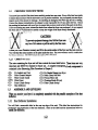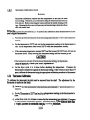
1
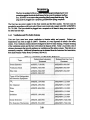
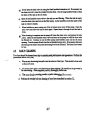
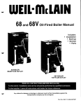
v
J
J
MI'S , PF28-03
Pita> Frialator '1..20-086-01
Rev00
Rev.Due 12117/93
~
NonCES
There are three different types of noti~s that you should be familiar with, a NO11CE, CAunON,
and WARNING. A NO11CE is a specialnote usedto call attention to a particularly important point
CAunON is used to point out a procedureor operation which may causeequipmentdamage. The
WARNING notice is the most important of the three becauseit warns of an operationthat may cause
personalinjury. Pleasefamiliarize yourself with your new rooter before operating it and heed the
notices throughout this manual. The WARNINGS are listed below and on the following page for
your review prior to operating the unit
~
SAFETY
SAFETY
SAFETY
SAFETY
SAFETY
The fryer is equipped with an oil proof, electrical supply oord with a three
prong safety plug. This is to protect operatorsfrom electrical shock hazard
in the event of an equipment malfunction. DO NOT cut or remove the
grounding (dlird) prong from this plug.
~==I
There is an open flame inside the fryer. The unit may get hot enough to set
nearby materials on file. Keep the areaaround the fryer free from combus-
tibles.
~==I
DO NOT supply the fryer with a gasthat is DOtindicated on the data plate. If
you needto convert the fryer to another type of fuel, oontactyour dealer.
DO NOT useanopenflame to checkfor gasleaks!
Wait S minutes before attempting to relight the pilot to allow for any gas in
the fryer to dissipate.
1~:i~:~:~::::;;11I
Nevermelt blocksof shorteningon top of
a fire, andvoid your warranty.
Water and shortening DO NOT mix. Keep liquids away from hot shortening.
Dropping liquid frozen food into the hot shorteningwill causeviolent boiling.
At operatingtemperaturethe shorteningtemperaturemay be greaterthan
3OOoP.Extremecareshouldbe usedwhenfiltering operatingtemperature
shorteningto avoid personnelinjury.
;AFETY
SAFETY
SAFETY
SAFETY
SAFETY
SAFETY
S~FETY
S:AFETY
SAFETY
S:AFETY
It will be easierandsaferif thefilter assemblyhasoooledto room temperature
before handling any filter parts.
Ensure that the fryer can get enough air to keep the flame burning oorrectly.
If the flame is starvedfor air it can give off a dangerouscarbonmonoxide gas.
CarbonMonoxideis a clearodorlessgasthat cancausesuffocation.
[:~:::;:::~:::;;;;III
A cooker equippedwith castersand a flexible power cord, must be connected
to the gas supply with a Quick-Disconnect devi~. This quick disconnect
must comply with ANSI Z24.41. To limit the movement of the cooker
without dependingon the connectoror quick disconnect, a restraining cable
must also be installed.
The power supplymust be
applian~.
SAFETY
SAFETY
SAFETY
SAFETY
SAFETY
Tableof Contents
Title
Section
Safety
-
Notice
Tableof Contents
Ust of TablesandFigures
1.1
1.2
1.2.1
1.3
1.3.1
1.3.2
1.4
1.4.1
1.4.2
1.4.2.1
1.4.2.2
1.4.2.3
1.4.2.4
1.4.3
1.4.4
1.5
1.5.1
1.5.2
1.5.2.1
1.5.2.1.1
1.5.3
1.5.3.1
1.5.3.2
1.5.4
1.5.5
1.5.6
1.5.7
i-ii
ill
WInCH FRYERDO I HAVE?
CHECKINGYOUR NEW FRYER
Cleck Your Order
ASSEMBLY AND LEVEUNG
HeatDeflectorIn..ct31lation
Leveling
INSTAUA 110N
InstallationClearan~
GasConnection
FuelTypes
GasLine Connection
Quick DisconnectGasConnection
Fuel SupplyLine Leak andPressureTesting
ElectricalConnection...
VentilationandFire SafetySystems
INl11AL ADJUSTMENTS
Visual Checks
BurnerIgnition Systems
lighting Instructionsfor ManualPilot Lights
Pilot FlameAdjustment
Main BurnerSystem
GasLine Requirements
BurnerAdjustment
Initial Cleaning
ThennostatCalibrationCheck
ThennostatCalibration
High Limit Test
...
...
~
...
1-1
1-2
1-2
1-2
1-2
1-3
1-3
1-4
1-4
1-4
1-5
1-5
1-5
1-5
1-6
1-7
1-7
1-8
1-8
1-9
1-11
1-12
1-12
1-13
1-14
2:
2.1
2.1.1
2.1.2
2.2
f1LLING nIB FRYER
Filling theFryer With Liquid Shortening
Filling theFryer With Solid Shortening
MELTING SOLID SHORTENING
i
2-1
2-1
2-1
2-2
Tableof Contents(Continued)
Section
ntle
Page
2.3
2.3.1
2.3.2
2.3.3
2.4
2.4.1
2.4.2
2.S
OPERA11NGINSTRUcnONS
Fryer Start-Up
Fryer Shutdown
PowerFailure ... ...
" ..,..
SHORTENINGFILTER PROCEDURES
.,.,."
GeneralFilter Hints
Filter Procedures.
DAn.,Y CLEANING
3.1
3.2
3.3
3.4
3.4.1
3.4.2
Fll..TER MEDIA REPLACEMENT
WEEKLY FRYER CLEANING (BOIL OUT)
f1..UEINSPEC'fION
TROUBLESHOOTING
Fryer Troubleshooting
Filter Troubleshooting...
ii
,..",.,...,..."
...
2-2
2-2
2-3
2-3
2-4
2-5
2-6
2-7
,..,
...
...
3-1
3-4
3-4
3-5
3-5
3-6
List of Tablesand Figures
1-1
Fryer Model Information
1-2
Ventilation andFire SafetyReferences
Title
Figure
1-1
1-2
1-3
1-4
1-5
InsideView of Fryer
Pilot Assembly,FlameAdjustment
GasVaJveShowingLocationof PressureRegulatorand Pilot Adjusters
Main BurnerConditions
Air Collar
2-1
Fryer mustratingFilter Components
3-1
Filter Module
iii
1-1
1-6
Page
1-9
1-9
1-10
1-11
1-12
iv
Chapter 1: GeneralInformation and Installation
The frying systemyou have selectedfor your establishmentis the Pita> Frialator Model SF14 UFM
series.This model oombinesthe oonvenienceof built-in filtration andthe compactnessof underfryer
filtration into one easyto useunit. This fryer will give you many yearsof reliable service if you follow
the simple operation and maintenanceproceduresin this manual. Containedin this manual are the
general installation, operation, and maintenanceproceduresfor the SF14UFM and SFI4RUFM.
1.1
WHICH FRYER DO I HAVE?
There aretwo modelsavailablewith solo filters andboth canusethe sameoptions. To find out which
model you have, look inside the door at the equipment identification plate. This plate has a lot of
useful information, but to identify which fryer you have,look at themodel numberblock. The model
number identifies which fryer and what featuresyou have. A brief description of each model and
it's features is provided in table 1-1.
Table 1-1 FryerModel Information
1-1
1.2
CHECKING YOUR NEW FRYER
Your new fryer and it's filter havebeen carefully packedinto one crate. Every effort basbeenmade
to ensurethat your fryer will be delivered to you in perfectcondition. As you unpackyour new fryer,
inspect each of the pieces for damage. If something is damaged,DO NOT sign the bill of lading.
Contact the shipper immediately, the shipper is only responsiblefor 15 days after delivery. Check
the packing list enclosedwith your fryer to ensurethat you havereceived all of the parts to the fryer.
If you are missing any parts, contactthe dealerfrom whom the fryer was purchased.As you unpack
the fryer and it's accessoriesbe careful to keep the weight of the fryer evenly distnbuted.
CAunON
To preventequipmentdamage,don't tilt the fryer onto
any two of it's castersor pull the unit by the flue vents.
Locate your Pitco Frialator warranty and fill in the serial number of the fryer and the date received.
Y 00 will fmd the serial number on the plate inside the door. Put your warranty card in a safe place
for future referen~. DO NOT return the card to Pitco Frialator.
1.2.1 Check Your.
The cratecontainingthe fryer unit will alsocontainthe itemslisted below Theseitemsarevery
importantand MUST be retainedfor future use. A completedescriptionof eachoomponentis
containedin the ShorteningFilter Procedurein Chapter2.
(2)
(2)
(1)
~)
(1)
(1)
Fry basketsper fryer
PitcoOeanerSample
Filter Crumb Catch
Filter Paper
FryerCrumbScoop
HeatDeflector
1.3
ASSEMBLYAND LEVEUNG
(1)
(1)
(1)
(1)
(1)
Fry BasketHangerper fryer
Drain OeanOut Rod
PrecoatFilter Aid
OeaningBrush(Fryer)
Filter CrumbSa>op
Whenyou receiveyour fryer it is completelyassembled
with the possibleex~ptioD of the heat
deflector.
You will find a removablelabel at the rear top edgeof the unit. This label hasinstructionsfor
positioningand installationof the heatdeflector. Referto the label andthe instructionsbelow to
installthe deflector.
1-2
a. Removethe two self-drilling saews from the top, back area of the cooker.
b. Position the heat deflector so that the angledportion of the deflector is facing toward the
front of the fryer. Securethe heat deflector to the back of the unit using the sheetmetal
saews previously removed.
~:=I
DO NOT obstruct the flow of combustioD/ventilationor air openings around
the fryer. Adequatecl~
around the fryer is necessaryfor servicing and
proper burner operation. Ensure that you meet the minimum clearances
specified in the installation instructions.
Co
When properly installed the angledsection of the heatdeflector will extend over the flue
openingto redirect the heal It SHOUlD NOT rover the flue opening. Nothing should
block the flue opening as this will causethe fryer to overheat and produce dangerous
gases.
1.3.2. Leveling
Using an appropriatewrench and level ensurethat the unit is level.
a. Place the level acrossthe front of the tank and rotate the adjustment on the front legs to
level the unit.
b. Perform stepa to level the unit front to back by placing the level along the side of thetank.
1.4
INsrAL1.ATION
Although it is poSSIblefor you to install and set up your new fryer, it is STRONGLY recommended
that you have it doneby qualified professionals. The professionalsthat install your new fryer will
know the local building codes and ensurethat your installation is safe.
~==I
The fryer must be properly restrainedto prevent movement or tipping. This
restraintmust prevent thefryer from movementsthatwould splashhot liquids
on personnel. This restraint may be any means(alcove installation, adequate
ties, or battery installation).
1-3
Non-Combustible
Construction
6"
6"
N/A
Combustible
Construction
Back
Sides
6"
6"N/A
In addition to the clearancesrequired for proper fryer operation, there must be at least 23 inches of
Your fryer will give you peak performancewhen the gas supply line is of sufficient size to provide
thecorrect gasflow. The gas line must be installed to meet the local building codesor National Fuel
GasCode (NFPA 54-1984) and ANSI Z223.1-1988 Latest Edition. In Canada,install the fryer in
aax>rdancewith CAN/CGA-B149.1 or .2 and local codes. Gas line sizing requirements can be
determinedby your local gas company by referring to National Fuel Gas Code,Appendix c, Table
C-4 (natural gas) and Table C-16 (propane). The gas line needsto be large enough to supply the
necessaryamount of fuel to all applianceswithout losing pressureto any appliance. Other factors
that are used to determine the piping requirementsare BTU requirements of the appliances being
oonnectedand the length of pipe betweenthe meter (main shut oft) and the appliances.
[:::1
NEVER supply the fryer with a gas that is Dot indicated on the data plate.
Using the inoorrect gas type will causeimproper operation. If you need to
1.4.2.1 Fuel~s - Each fryer is equippedto work with one type of fuel. The type of fuel with
whichtheappliance is intended to operateis stampedon the data plate attadled to the inside of the
door.
DO NOT useanopen
for gasleaks!
1-4
1.4.2.2
Gas Line Connection
- Connect the fryer to the gas supply line with a oonnector that
amplies with the Standardfor Connectorsfor Movable GasAppliances (ANSI Z21.69-1987). If you
are installing a fryer with castersuse a quick disoonnectrefer to the Quick Disconnect installation
instruction, 1.4.2.3. Connect the gas line to the fryer using a pipe joint sealantthat is resistantto
liquefied petroleum. If the fryer was disoonnectedduring the fuel line testing,usea solution of soap
and water to leak test the new oonnection.
NonCE
NEVER use an adaptorto makea smallergas supply line fit the cooker
connedion. This may not allow proper gas flow for optimum burner
operation,resultingin poor cookerperforman~..
1.4.2.3
OuickDjsa)nnectGasConnection-Gasfryers
equippedwith castersmust be installed with connedors
thatcomply with theStandud for Connectorsfor Movable
Gas Appliances, ANSI 221.69-1987, and Addenda
Z21.69A-1989. This connection should include a quick
disconned device that complies with the Standard for
Quick Disamnect Devi~ for Use With GasFuel, ANSI
Z21.41-1989. When installing a quick disoonnectyou
mustalso install a meansfor limiting the movementof the
fryer. This device will prevent the gas line or the quick
disronnect from being strained. The restraining device
should be attached to the cooker on the back panel as
shownin the illustration. The quick disconnect,hose,and
restraining device can be obtained from your dealer.
-
1.4.2.4
Fuel SYR~IXLine Leak and PressureTestine The fuel supplysystemmust be tested
before the fryer is used. If the fuel line is going to be tested at a pressuregreaterthan (»1/2 PSIG
(3.45 kPa), make sure that the fryer is disamneded from the fuel line. If the fuel line is to be tested
at a pressureequal to or less than (s) 1/2 PSIG (3.45 kPa), the fryer can be COft-!!e-m.rlbut the unit's
gasvalve must be shut. Test all gasline connectionsfor leaks with a solution of soapand water when
pressureis applied.
1.4.3 Electrical Connection
The electrical servi~ usedby the fryer must oomply with local cx>des.If thereareno local a>desthat
apply, refer to the National Electrical Code (NEC) to install the servi~. In Canadarefer to CSA
StandardC22.1 and local codes. Wiring diagrams are provided inside the fryer door. The power
requirementsfor the fryer are shown below.
Input Voltage
Currentperfryer
120 V Ac, 60Hz
220 (or 240) V Ac, SOliz
7 Amps
3.s Amps
1-5
~=:I
The fryer is equippedwith an oil proof, threeprong (grounding) plug for your
protection againstelectrical shock hazardin theeventof equipmentmalfunction. DO NOT cut or removethe grounding (third) prong from this plug. This
plug must be plugged into a properly groundedthree prong receptacle.
The fryer has one power supply for the fryer controls and the filter module. The fryer must be
groundedin accordancewith local code; if there is not a local code,comply with NBC ANSI/NFP A
No. 70-1990. The fryer should be plugged into a receptacleat all times to keep power supplied to
the filter line heat tape.
1.4.4 VentilatioD and Fire Safety Systems
Your new fryer must have proper ventilation to function safely and properly. Exhaust gas
temperaturescan reach as high as 1200°F. Therefore, it is very important to install a fire safety
system. Your ventilation systemshould be designedto allow for easycleaning. Frequentcleaning
of the ventilation system and the fryer will reduce the chan~ of fire. Table 1-2 provides a list of
referen~ documentsthat provide guidanceon ventilation and fire safety systems. This table is not
necessarilycomplete. Additional information can be obtainedfrom the American GasAssociation,
8501 East PleasantValley Road, Ceveland, OH 44131.
Table 1-2. Ventilation and Fire Safety Referen~s
1-6
Excessive ventilation causesdrafts, which will interfere with the proper operation of the pilot and
theburner. Leaveat least18inchesof openspacebetweenthe fryer's flue vent opening andthe intake
of the exhaust hood.
CAU'I10N
Ensurethat your ventilation systemdoesnot causea down draft at the fryer's
flue opening. Down draftswill not allow the fryer to exhaustproperly and will
causeoverheatingwhich may causepermanentdamage. Damagecausedby
down drafts will not be covered under equipment warranty. NEVER allow
anything to obstrud the flow of combustibles or ventilation exiting from the
fryer flue. DO NOT put anything on top of the flue area.
NonCE
NEVER connectthe blower directly to the flue openings. The direct flow of
air will causepoor temperaturerecovery, poor ignition, inefficient operation
of the fryer, and could extinguish the pilot.
1.5
INI11AL ADJUSTMENTS
After your fryer hasbeeninstalled as describedin section 1.4, it needsto be adjusted to ensurethat
it will perform as designed. These adjustmentsmust be performed by a qualified person. To
perform theseadjustmentthe following tools will be needed:
..
Manometer (low pressuregauge)
DC Millivolt Meter
.
Digital Thermometer (Temperatureprobe)
1.5.1 Visual Checks
Before you begin filling and adjusting the fryer, perform the following visual
checks:
a. After thefryer is in its permanentlocation, check for levelness.Any
additional leveling that is necessarycan be perfonned as described
in section 1.3.
b. Oleck thetemperaturebulbs (thennostat/high-limit), locatedin the
fryer tank to ensurethat the mounting screws are tight The figure
showstheprobe typical location. Look down inside the fryer tanks
to seethe probes.
1-7
Ensure tIIIt Un.
8,. Nt 1_.
pen-
CAtmON
Before going any further, fill the fryer with WATER. Water is usedfor the
installation adjustments becausethe temperaturewill never exceed 212°F
(100°C) therebyallowing plenty of adjustmenttime. Never let thewater level
go below the OIL LEVEL mark on the rear of the tank.
G;:a
There is an open Bameinside the fryer. The unit may get hot enoughto set
near by materials on fire. Keep the area around the fryer free from
1.5.2.1
Li~htin& Instroctions for Manual Pilot l1ihts
-To light the pilot light refer to these
instructionsandFigure 1-1. Thenumbersin parenthesis
referto Figure 1-1callouts.
G:::I
Wait 5 minutes before attempting to relight the pilot to allow for any gas in
thefryer to dissipate.
a. Openthe gassupplyvalvesto the fryer.
b. Openthe fryer's door to gain accessto the controls. Turn the thermostatcontrol knob (1)
counterclockwise to the off position.
c. Turn the Unitrol gasvalve knob (tan knob) (2) to the Pll..OT position and
push in on the knob. Hold the knob in for approximately one minute to
purge the air out of the line. Hold a flame to the pilot light until the pilot
(3) ignites. This may tate a little while the first time you light the fryer
becauseof air in the lines. Once lit, hold the knob in for approximately
60 secondsand then release.
(lJ
0
~
~ ~
d. If die pilot goes out wait 5 minutes and repeatstep c. If after three tries the pilot will not
remain lit, refer to the operator troubleshooting section of this manual.
e. Turn theUnitrol gasvalveknob(tan knob)counterclockwiseto theON
position.
f. Setthe thermostatcontrolknob to the desiredtemperaturesetting.
1.8
~~
g. The main burner (4) will light and be controlled by the thermostat. The pilot burner will
remain lit regardlessof the switch position.
1.5.2.1.1 Pilot Flame Adiustment - The pilot flame should be adjusted to prod~ the ~r
millivolt output from the pilot sensingdevi~. Millivolt output for the thermopile shouldbe between
300 and 500 millivolts. Figure 1-2 shows the pilot assemblywith examples of the incorrect and
correct pilot size. Example A illustrates a pilot flame size that is too small to produ~ sufficient
millivolt output. Example B is the correct size for proper millivolt output
TME~ll£
PILOT
IUDU \
\
\
M
B
A
Figure1-2 Pilot Assembly,
1-9
a.
This test requires a DC millivolt meter set to a scale of O-l(XK)mv.
b. Locatethe thermopile wires coming from the thermostat!HighLimit box going to the gas
shut off valve. The wire insulation size decreasesnear the gas valve connections.
Co
Connectthe negative(-)testprobeto pilot bracket.
d. Connectthe positive (+) testprobeto oneof the High Limit terminal
e.
Removethe pilot flame adjustmentcover.
PRESSURE REGULATORLOCATION
(UNDER CAP SCREW)
PILOT ADJUSTER LOCATION
(UNDER CAP SCREW)
g. Rotatethescrew in the directionto achievea readingof 400rlO mv for thermopiles.
NonCE
h. Replacethepilot flame adjustingscrewcover.
1-10
For the burners to work the gas supply valve must be open and the main power switch must be on.
The main burner receivesgasfrom the main gassupply through thethermostatically oontrolled valve.
When the therDlostatis turned up the gas control valve opens and the pilot will ignite the burners.
After the burner system is operating, perfOrDlthe burner adjustmentsin the following procedure.
Figure 1-5 illustrates the different oonditions possible for the main burner.
-liftofr
The
Theflame
flameseems to wli:
thefaa; of theburner.
To correct adjust main
described in
burner as describc
1.5.3.2.
EX~IVE
incoming gas pressure.
Adjust manifold pressureas
described in 1.53.2.
INsumCIENT
GAS PRESSURE
Figure 1-4 Main BurnerConditions
1-11
FLOW
1.5.3.1
Gas Une Rgrements - A properly installed gas supply system will deliver 7.0 %2.0.
W.Co
natural gas(12.0 %2.0.W.c.LP) to all appliancesoonnectedto the line, operatingat full demand.
Adjustthe
1.5.3.2
Burner Adjustment -The burnersmust be
burner flame using the following procedure.
a. Ensurethat the gas oontrol valve is in the OFF position. Remove the manifold pressure
tap plug and connect an accuratepressuregauge(rangeof 0-16" w.c. in 0.1" increments)
or manometer.
b. light the pilot burner (~ 1.5.2)for theunit being testedandadjustthe thermostatto light
the main burners.
c. The installed presswegaugereadingshouldbe tbesame,~.1., asthat markedODthedata
plate inside the door. If the pressureis correct go to step e, if DOt,adjust the pressure.
d. To adjust the pressure,removetberegu1atoradjustmentsaewcover(~ Figure 1-3). Use
a flat tip screwdriver to adjust the screw until the properpressureis reached. Turning the
~w clockwise will inaease the pressure,counterclockwisewill deaeasethe pressure.
f.
To removethe pressuregauge,turn gascontrolvalveto OFF. Removethegaugeand
install the pressuretapplug.
BURNER
ORIFICE
I"""""'~~
SET SCREW
BURNER FI1TING
GAS PRESSURE 1
TEST PLUG
Figure1-5 Air Collar
1-12
g. Now that the pressureis set for properoperation, set the main burner flame. Unlock the
air collars by loosening the set screwfor the collars. Turn the gas control valve to ON
and turn thermostatto light the main burners.
h. Adjusttheshapeandsizeby raising
with well definedinnercones.
provided.
1.5.4 INITIAL CLEANING
When the fryer is shipped,many of its parts arecoveredwith a thin coat of oil for protection. Before
the fryer is ready for cooking it must be cleaned. This will remove the oil coating and any foreign
matter that may have !.~JII!ulated during storageand shipment. Perform the cleaning as described
below.
a.
Fill the tank with water and add one packet of Pita> fryer cleaner or a mild detergent.
b. Turn the fryer on and set the thermostatto 200~. Allow the fryer to heat for 15 minutes.
NonCE
Do not leave the fryer unattendedduring cleaning. Never let the water level
go below the "OIL LEVEL" mark on the back of the tank.
c. Using the fryer cleaning brush, scrubtheinside of the fryer to remove protective coating.
d.
When cleaningis complete, turn off thefryer main burnersand turn gasvalve knob to the
PILOT position. If the fryer haselectronic ignition turn the gas control valve to the OFF
position. Drain the water into a containersuitable for hot water and dispose of it.
e. When the tank hasoooled, rinse it thoroughly with 0001water. Continue to rinse the tank
until the cleanerhas been rinsed, thoroughly from the tank.
,
f.
Using a cleandry cloth, wipe out all of the water. Be very thorough removing the water,
becauseany residual water will causehot oil to splatter out of the fryer.
CAImaN
Mild steel tanks must be wiped down/coatedwith oil to keep the tank from
rusting.
g.
Now that the tank is clean, you are ready to fill and operate the fryer. Refer to 2.1 for
instructions on adding shortening to the fryer.
1-13
loSoS
Thermostat Calibration Check
NOnCE
Thermostat calibration requires that the temperature of the fryer be raised
aboveboiling. Therefore, you will needto drain the water from the fryer and
fill it with oil. Before removing the water, perform the initial cleaning of the
fryer. Oeaning the fryer now will preventyou from having to drain the oil and
refill with water later.
Filling thefryer with oil is describedin 2.1. To perform the calibration checkdetailedbelow you will
needa digital thermometer.
b. Set the thermostat at 325°F and wait for the temperaturereading on the thermometerto
rise. As the temperature rises toward 325°F watch the thermometer closely.
c. If the shortening temperaturereaches350oPand the burners DO NOT turn off, turn the
thermostatdown. Keep lowering the thermostatsetting until the burners go out.
CAtmON
(X)uld be defective.
Contactyour ASAP representative.
d. Let the fryer cycle 4 to 6 times before checking the temperature. Compare the
thermometertemperatureagainstthe thermostatsetting. If the values are more than 5°F
apart,calibratethe thermostatusing the appropriatecalibration procedurein this manual.
1.5.6 1bennostat Calibration
To calibratethe thermostatthe dial must be removedfrom the shaft. The adjustmentfor the
thermostatis insidethe dial shaft.
a. Placethe
sensors.
b. SettheThermostatto 325Ofandwait for thetemperaturereadingon thethermometerto
rise.
c. Let the fryer cycle 4 to 6 timesto ensurethatthe temperaturehasstabilized. Compare
5°F apart,calibratethe thermostatusingthe
1-14
If thevaluesaremorethan
procedure.
d. Setthe thermostatdial to 32S°F.
e. Remove the thermometerdial by pulling the knob straight out. DO NOT rotate the dial.
f.
Hold the outsideof the shaft soit doesnot move. Use the tip of a small, flat tip screwdriver
to scrapeaway the sealing compoundfrom the adjustment screw.
g. Turn the adjustmentscrew clockwise to lower the temperaturesetting and counterclockwise to raise the temperature. One quarter turn changesthe temperatureapproximately
25°F.
h. Turn the adjustmentuntil the burnersturn on at 32S°F. Repla~ the knob and allow the
fryer to cycle 4 to 6 times. Check the temperature of the thermometer against the
thermostat dial, if it is greater than 5°F differen~ repeat the calibration procedure.
i. Whenthecalibrationis correct,removethethermometerandrep1aC%
the tubesaeen.
1.5.7 HIgh Umit Test
TIllS TEST SHOULD BE PERFORMED BYOUAUFIED PER.~ONNELONLY
1-1'
1-16
Chapter 2:
This chapterdescribeshow to operateyour fryer to obtainthebestperformance.Includedin this
chapterarefilling, operating,andcleaninginstructionsfor gasfryers.
2.1
FIUJNG THE FRYER
Both liquid and solid shortening can be used in the fryer. If solid shortening is used, it is
recommendedthat you usethemelt cycle feature(optional) to melt the shortening. You canmelt solid
shortening without the melt option, but you must carefully follow the instruction in section 2.2.2.
2.1.1 FUlingthe Fryer With liquid Shortening
a. Makesurethe drainvalveis completelyclosed.
b. Fill the fryer with oil to the "Oil Level" line markedon
theback of the tank.
2.1.2 FllllDg the Fryer With SoUdShortening
.. -.
~==I
Nevermelt blocksof solid shorteningon top of the burner
tubes. This will causea fire, andwill void your warranty.
Pa.
a.
Make sure the drain valve is completely closed.
b. Remove the screenoovering the tubes.
c. Cut the shortening into cubes DOlarger than I". ALWAYS pack the shorteningbelow, between, and on top
of the burner tubes. DO NOT leave any large air gaps.
Use care when packing the solid shortening in the tank.
DO NOT bend or break the temperaturesensorprobes.
If thesearedamagedthe fryer will not function properly.
~
d. Once the fryer is packedwith shortening, the shorteningmust be melted. To melt the
shortening refer to the Fryer Start-Up section for your fryer
2-1
2.2
MEL11NGSOLID SHORTENING
NonCE
The melting procedurebelow requiresthe manualcycling of the fryer. Watch
carefully for smoke. If smoke is noticed, die shortening is scorching. To
prevent this, decreasethe time you leave the burners on.
a. Rotatethethennostatto causethemain burnersto light andremainlit for 4 seconds.
b.
Rotate the thermostat back to off for 30 seconds.
c.
Continue cycling the main burnersuntil most of the solid shortening is liquefied and the
temperaturereaches150°F. At 150°Fleave the thermostatsetat the desiredtemperature.
The burners will remain on constantly until the shortening temperature reaches the
thermostat setting.
d. On~ at temperature,the fryer is now operating normally and ready to use.
2.3
OPERATING
IN~UCl10NS
To ensurethe food always comesout the very best, follow the preparationinsttuctions for the food
you arecooking. Using the best shorteningmakesthe bestfried foods. The best shorteningwill last
longer than lower gradeshortening and saveyou money. When not in use the shortening should be
cooled and covered to prevent contamination.
CAU110N
The fryer hasbeeninstalledusingrestrainingdevicesto preventaccidental
tippingor movement.Do notattemptto movethefryerwhenit hashot 1
in it. Splashinghot liquids cancauseseverebums.
[==~
Water andshortening DO NOT mix. Keep liquids awayfrom hot shortening.
Dropping liquid frozen food into thehot shorteningwill causeviolent boiling.
2.3.1 Fryer Start-Up
DO NOT sf ART FRYER Wn'HOtn' FILUNG WITH OW
a. Ught the pilot light asdescribedin section1.5.2.
2-2
knob is located behind the front doors or on the front oontrol panel.
c. The main burnerswill light and cycle at the thennostat setting.
2.3.2
Fryer Shut-Down
There are two shutdownmodesof fryer operation,STAND BY andCOMPLETE. The standbymode
removesthe ability for the fryer's main burnersto cycle. Complete shutdown turns off the gassupply
to the fryer. Shut down the fryer by:
STANDBY
COMPlEI'E
Turn the thennostatto OFF. Depressand turn thegasvalve clockwise
to the PILOT position (if fryer has an electronic ignition turn the gas
valve to the Off position). Thefryer is now in Standbyand can remain
this way for only brief periodsof time. NEVER leave the cooker in
standby overnight.
To oompletely shut down thecooker,turn the gasvalve counterclockwise to the OFF position andturn the power switch off (if used). The
fryer is now completely shut down and can be cleaned and filtered.
2.3.3 PowerFailure
~
~
0
If power is removed from the fryer during filtering, place the filter switch in the OFF position and
close the return valve. When power is restoredrestart the filter procedure
'--I
2-3
2.4
SHORTENING FILTER PROCEDURES
This sectiondescribesthe proceduresusedto filter fryers using the solo filter unit. Figure 2-1 shows
the locations of the componentsusedin thefilterproc:ess. The filter accessoriesandtoolsyoushould
have to perform normal filtering operationsare described on page 2-5. Frequent filtering of your
shortening will prolong the shortening's usable life.
Daily shortening filtering is strongly
recommended .
Hush Hose
Valve
optional)
Return
Valve
Drain Valve
Handle
NOTE
SeeMaintenance
Sectionfor Filter
Operational
Information.
ValveHandle
Valve Body
VALVE CLOSED
(HandleAcross Body)
VALVE OPEN
(Handle Inllne With Body)
Figure2-1 FryermustratingFilter Components
2-4
Return Valve
pump on, allows the shorteningto returnto the design,this sooopis usedto removethe debris
fryer tank.
from thefilter pan.
Drain Valve BLACK - Drain theoil from the Cleaner- Usedduringfryer boil-out cleaning.
fryer tanksto thefilter pan.
oil from the filter unit to thefryer. Simplypush
to left ODfitting to connect. Pull to right to PreooatFUterAId . CoarseDiatomaceousearth
used to enhance the filter ability of the filter
disa>nnect.
media.
Filter Unit Cord - Provideselectricalpowerto
Cleaning Bnlsh -This long handled stiff bristle
brushis usedto brushdown the crumbsinside the
fryer tank during shortening filtering.
the illter unit.
FUter Paper
Packageof pre-cutfilter
FIlter Crumb Catch - Mounts in d1efilter panlid
and catcheslarge debris during filtering.
FryerCmmbScoop-Aspecia11y
designed
long
handlescoopfor scoopingout the fryer. The
scoopsectionis narrowenoughto fit down be- Attached to the tweenthefryer burnertubes.
flush Hose (OPl10NAL)
filter piping, this hoseand nozzle is usedto flush
out the fryer tank. This hose is an optional item.
~;=I
At operatingtemperaturethe shorteningtemperaturemay be greaterthan
300°F. Extremecareshouldbe usedwhenfiltering operatingtemperature
shorteningto avoidpersonalinjury
2.4.1 GeneralFDter Hints
Ensurethat all oil in thefilter pan is returned
importantif you areusingsolid shortening.
This is very
Always usePitco Precoad for fastestfiltrations,maximumlaborsaving,andcleanest/
clearestshorteningpossible.Impairedfilter performance
will resultwithout theuseof
a filter aid.
The longevity of your oil is relatedto how cleanyou keepit. With a Pitco solo filter
system,it is easyto do a quick drain/refill anytime. By removingsuspended
particles
often,it preventsthemfrom burning.
2-5
4. When the time it takesto refill the fryer after filtering exceeds3:00 minutes, scrape the
filter bag or paper. If scrapingdoesnot bring the refill time back down changethe fi1ter
paperasdescribedin 3.1.
S. The mter pump is protectedfrom dogging by a specialscreenin the pickup tube.
Cean this screeneachtime a new mter is installed (seeChapter 3, 3.4.2)
6. If you havefilter systemproblemsreferto section3.4.2.
7. Purgethe filter linesby allowingthefilter pumpto run lS secondsafterair bubblesare
seeninsidethe fryer tank.
2.4.2 Filter Procedures:Numbersin parenthesis
referto Figures2-1 and2-2.
NonCE
.
When working with hot oil ALWAYS wear oil-proof, insulated gloves.
NEVER
.
.
.
.
Run the filter systemwithout a filter bagtpaper.
Attempt to filter more than one fryer tank at a time.
Empty the oil from the fryer before turning OFF the fryer burners.
Store the UFM Filter Unit anywhereother than in the fryer filter cavity.
a. Disconnect die filter pan, slide it out and empty the crumb basket. Scrapepreviously
filtered residueoff the filter paper. Examinethe filter bagfor dark, scuffed, or tom areas.
Refer to 3.1.1 for filter bag replacementinstructions. Re-install the pan.
b.
Turn die fryer OFF (SeeStandbyShutdown,section2.3.2). Removethebasketsfrom the
fryer tank(s). Use the cleanout rod to lift out die tube screens.If thereareexcessaumbs
in the fryer tank, remove them with the crumb scoop.
Co
If you have replacedor scrapedthe filter paper,stir in Preooat
Filter Aid to the shorteningin fryer (8 oz. by volume). After
cleaning out the excessdebriswith thefryer sooopsprinkle the
powder into the first fryer to be filtered andstir thepowder into
the oil.
NonCE
Always opena
valvebeforestartingthefilter pump.
2-6
d.
Slowly open the drain valve by using the black knobbed extension rod. If necessaryuse
the clean-out rod to clear the crumbs from the drain. Use the long handled brush to clean
the sides of the tank as the oil drains.
e. Open the red handled return valve to the tank you are filtering.
When the tank is empty
closethe drain valve and turn on the filter pump. As the tank fills, brush the inside of the
tank to remove crumbs.
f. When bubbles are seencoming out of the oil return spout, turn off the pump. Open the
drain valve and allow the tank to drain again. Repeatstepsb through d until the tank is
clean.
g.
2.5
When cleaning is oompleteturn the pump off, close the drain valve, and repla~ the tube
screen. Open the red handledreturn valve and turn on the pump to refill the fryer with
the filtered oil. Continue to run the filter pump until bubbles oome out the oil return
opening. Turn the pump off andclosethe red handledreturn valve. If necessaryaddmore
shorteningto the tank to returnthe shorteninglevel to the fill mark. The fryer is now ready
for use.
DAILY CLEANING
Your fryer should be cleanedevery day to maintain peakperformanceand appearan~. Perform the
procedures below every day,
a. Wipe up any shorteningthat spills onto the exterior of the fryer. This should be donewith
a clean soft cloth.
b. Use WamI water with a mild detergentto clean surfaces. Be careful not to get water in
theshortening.Rinsecompletelyanddry thoroughlybeforeuse.
Co Use.
scouringpowderor padto dean stainsif
d. Performthe weeklyboil out cleaningof your fryer deSCrIbed
in section3.2.
2.7
2-8
Chapter 3: Owner Maintenanceand Adjustments
This chapterprovidesyou with the informationandproceduresnecessaryto performbasicfryer
mainteDan~and adjustments.If after performingmaintenan~on your fryer it doesnot perform
properly,contactyour
The power supply
appliance.
3.1
~TER
[==-
before
be disconnected
or cleaningthe
MEDIA REPLACEMENT
the proceduresnecessaryto replacethe filter
This section the filter system'scomponentsand
media.
~=:I
At operatingtemperature,the shorteningin thefryer may be hotter than375Of
(190°C). This hot, melted shorteningwill causeseverebums. Do not let the
hot shorteningtouch your skin or clothing. Always wear insulatedoil-proof
gloves when working on the filter system.
The filter module storesneatly under die fryer. The unit is very easy to use and allows for quick
installation and filtration, even under die busiest conditions. The filter module is shown in Figure
3-1 widl specific componentsand features pointed out and briefly described.
Follow the proceduresbelowto
the fIlter
~=:I
It will be easierandsafer if the filter assemblyhascooled to room temperature
before handling any filter parts.
a. To removethefilter pan,disconnectthefilter tubeoonnection.This is doneby sliding
the insulatedportionof theconnectorout of the receivingportionof the oonnector.
filter panandgently pull the assemblyout the front of the fryer, removethe flIter
b. Graspthe
pan lid.
Remove the aumb catch tray from the top of the filter pan. Discard any debris that may
be in the crumb catch.
3-1
c:
,
@
Figure3-1 Filter Module
(1) Fdter Pan - Holds the oil from the fry tank. (5) Flexible Coupling. Flexible coupling allows
for easymovementwhen connectingand discon(2) Pick-Up Tube - ConnedSfilter envelope necting the pickup tube from the fryer.
assemblyto piping. Inoorporatesa strainerto
protect filter pump from grit in the event of (6) Casters . Allows for easy movement of the
envelopefailure.
pan.
(3) FOter Assembly CoDDector - An insulated
handlecoversthe filter pan assembly connection.
This connection separatesthe filter pick-up assembly from the filter piping for removing the
filter pan for cleaning.
(4) FOter Media Connector -Connectsthe filter
pick-up tube to the filter media rack. An internal
screenkeeps debris out of the filter pump.
3-2
d.
Lift up on the filter paperassemblyand removefrom the filter pan. Unscrew the suction
tube from the filter papersupport rack. Removethe clip screenand slide the filter paper
support rack assemblyout of the filter bag.
e. All of the filter pick up assembly
~
0
000
f.
g.
parts can be washedin a dish washer
or a pot sink. Hush out the suction
tube assembly with hot water. The
pick up tube screen keeps grit and
solid material from binding thepump.
After flushing thepick up tube screen
check to ensurethat the screenis free
of debris. After cleaning, it is very
important to thoroughly dry the parts
before re-assembling. Water and oil
do not mix. Water in hot oil will
causethe oil to splatter.
Tube
Pick
aip
(Designed
low
scraping
sedimentwith out
tearing paper)
Start fe-assembling the filter pick up
assembly by sliding the new filter
paper on to the filter paper support
rack. Ensure that the hole in the filter
paper goes over the pick up tube assembly threadedconnector.
'Filter
Paper
SupportRack
Conn
~
Fold the open endof thebag in two folds. The fIrSt
fold should be approximately 1 inch from the end
and the secondshould be over the edgeof the rack
assembly.
h. Slide the clip screenoverthe folded endof thefilter
paper. Ensure the opening of the clip screengoes
over the pick up tube connection. Screw the
suction tube assemblyonto the threadedconnection.
i. Placethefilter rackassemblyin thefilter panandinstall the aumb catchtray in thetop
of the filter panlid. Placelid on filter pan.
j.
Slidetheillter panassemblybackinto thefryer andattachthepick up tubeconnectorto
the filter unit connection.
3-3
3.2
WEEKLY FRYER CLEANING (BOIL OUT)
The fryer shouldbe thoroughlycleanedoncea week. This cleaningshouldinclude a complete
drainingof the fryer and a boil out. This would alsobe a goodtinle to replacethe filter paperif
necessary
.
a. You will needa containerlargeenoughto hold thevolumeof thetank. This container
shouldalsobe ableto withstandboiling watertemperatures.
CAU110N
Completely shut down the fryer when the oil is to be replacedby water, and
when the heating portion of the cleaning is complete. This will prevent the
heating system from coming on during the oil draining and water filling
procedure.
b.
Drain the oil from the fryer and discard or savefor reuse. Removetube rack/meshtube
screensand remove any large debris from the bottom of the fry tank. Once clean, return
tube rack/mesh screensto the fry tank. Cose the drain valve and fill the fry tank with
water and noncaustic detergent. For best results use Pita> Fryer Cleaner.
c. Restartyour fryer asdescribedin 2.3andsetthethermostatto 200°F and bring the water
to a slow boil. DO NOT allow water to boil becauseexcessiveJ
will occur.Once
the wateris at a slowboil turn off thefryer.
d.
Allow the fryer to soakfor 20 minutes to softenshorteningdepositsandcarbon. Use fryer
brush to remove any residuefrom tank, beatingtubes, and side walls. Perform the daily
cleaning procedure describedin section 2.5.
e. Removethe filter unit from under the fryer. Slide a containerto catch the water under the
fryer so that the pipe that is nonnally aimed into the filter pan is aimed into the container
and open the drain valve.
f. Drain the hot waterto theoontainerandrinsethe tankwith cleanwarm water.
g. Wipethe tank dry with cleancloth wipes. Closethedrain valveandremovethe large
h. Referto section2.1 to refill the fryer.
3.3
FLUE INSPECI'lON
It is recommendedthat once every six months, with the cooker cooled down, you examine the flue
area. Check for corrosion or blockageof the flue. Ensurethat the cooker is shutdown anddo not turn
it on during the examination. Examination of the flue areaduring cooking may causebodily injury.
3-4
3.4
TROUBLESBOO11NG
This section is provided to aid you in the event of fryer or filter troubles. If thesetroubleshooting
procedures do not correct your problem contact a qualified technician or the factory. The
troubleshootingprocedures
arein a flowchartformat.
3.4.1 Fryer Troubleshooting
Refer to this section to correct common problems that may be encounteredin equipment operation.
3-5
3.4.2
Filter Troubleshooting
Refer to this section to correct common problems that may be encounteredduring filter operation.
3-6
~
YES ~*-.
YES
b*8 ~
~
..~.
~
"-8
~
~
.. PI8I1»
MIdI ON.
~..~~
~"~\I8Iv."'I.n~~
.-u
~~
be
~ lie ~
dI8dWg8
~10~12~
e
..
... .. ~ bI'
~ ..
t.-8~
..-1.JIDe'
~ ...
- 8'8.
Sold8tut81~ ~
~
oWtie ~
be
di8dwge
... ~10~12"""
YES b*8 mq 1118
~
8WId1
ON. If tie .. hM been
,. ...- ~
tyer
..
".~...b'45
b8b8
~.
tC)
~ .. de8ed
v8V8
... ...
"'_1d8d
ra~~.
~
~
..va ~.~~-,
~~..~.
~..
~b*8~.~
--~~..
~..~..
-~
«*aJI:
~.
)-7
3-8
v
~
I
..,