1
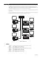
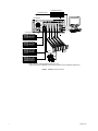
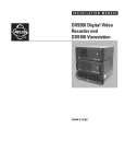
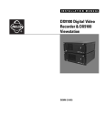
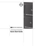
I N S TA L L AT I O N / O P E R AT I O N
®
DX9000 Series
Digital Video Recorder
DX9000F-C Series & DX9000H-C Series
C685M-D (2/03)
CONTENTS
Section
Page
IMPORTANT SAFEGUARDS AND WARNINGS .................................................................................................................................................................. 3
DESCRIPTION ..................................................................................................................................................................................................................... 4
MODELS .................................................................................................................................................................................................................... 4
INSTALLATION .................................................................................................................................................................................................................... 5
MOUNTING ............................................................................................................................................................................................................... 6
CONNECTIONS .......................................................................................................................................................................................................... 7
SYSTEM CONFIGURATION ........................................................................................................................................................................................ 9
NETWORK CONNECTION ......................................................................................................................................................................................... 13
INSTALLATION COMPLETION .................................................................................................................................................................................. 13
SPECIFICATIONS ................................................................................................................................................................................................................ 14
REGULATORY NOTICES ..................................................................................................................................................................................................... 15
WARRANTY AND RETURN INFORMATION ...................................................................................................................................................................... 15
LIST OF ILLUSTRATIONS
Figure
1
2
3
4
Page
DX9000 System ................................................................................................................................................................................................ 4
Installation of Support Rails ............................................................................................................................................................................. 6
DX9000 System Connections ........................................................................................................................................................................... 8
Server Configuration ....................................................................................................................................................................................... 10
LIST OF TABLES
Table
A
2
Page
Video Coaxial Cable Requirements .................................................................................................................................................................. 7
C685M-D (2/03)
IMPORTANT SAFEGUARDS AND WARNINGS
Prior to installation and use of this product, the following WARNINGS should be observed.
1.
Installation and servicing should be done only by qualified service personnel and conform to all local codes.
2.
Unless the unit is specifically marked as a NEMA Type 3, 3R, 3S, 4, 4X, 6, or 6P enclosure, it is designed for indoor use
only and it must not be installed where exposed to rain and moisture.
3.
The installation method and materials should be capable of supporting four times the weight of the unit and equipment.
The product and/or manual may bear the following marks:
This symbol indicates that dangerous voltage constituting a risk of
electric shock is present within this unit.
This symbol indicates that there are important operating and maintenance instructions in the literature accompanying this unit.
CAUTION:
RISK OF ELECTRIC SHOCK.
DO NOT OPEN.
Please thoroughly familiarize yourself with the information in this manual prior to installation and operation.
CAUTION: Do not run any software applications on the ViewStation other than those authorized by Pelco.
C685M-D (2/03)
3
DESCRIPTION
The DX9000 Series Digital Video Recorder (DVR) is an ultrahigh-end recorder that can record images simultaneously from as
many as 40 cameras at 15 ips or from as many as 24 cameras at 30 ips. The DVR allows simultaneous viewing of live or
recorded video, in any combination, from as many as four cameras. The user can even watch three recorded streams and a live
stream from the same camera while other users on the network are accessing the same camera.
The recorder is part of the DX9000 system that also includes video storage units for saving video images and ViewStations for
observing video.
When multiple DX9000 recorders and ViewStations are linked to each other through a LAN (local area network) or WAN (wide
area network), literally thousands of cameras can be recorded and viewed at the same time.
ETHERNET SWITCH
VIEWSTATION 1
RECORDER 1
STORAGE UNIT
RECORDER 2
VIEWSTATION 2
STORAGE UNIT
RECORDER N
VIEWSTATION N
STORAGE UNIT
Figure 1. DX9000 System
MODELS
DX9008F-C
DX9016F-C
DX9024F-C
DX9008H-C
DX9016H-C
DX9024H-C
DX9032H-C
DX9040H-C
4
Eight-channel digital video recorder, 30 ips for each camera, Revision C software
Same as DX9008F-C, except has 16 camera inputs
Same as DX9008F-C, except has 24 camera inputs
Eight-channel digital video recorder, 15 ips for each camera, Revision C software
Same as DX9008H-C, except has 16 camera inputs
Same as DX9008H-C, except has 24 camera inputs
Same as DX9008H-C, except has 32 camera inputs
Same as DX9008H-C, except has 40 camera inputs
C685M-D (2/03)
INSTALLATION
Make sure all of the supplied items are present.
1
2
1
1
1
2
4
12
4
2
1
Recorder
Power cords (1 USA standard and 1 European standard)
Patch panel
1-5 BNC mounting plates
1-5 37-pin connectors with 24-inch (61 cm) sets of coaxial cable and BNC connectors
2-10 Screws, 6-32 x .375-inch, black, pan head
4
Screws, 10-32 x .750-inch, black, pan head
Keyboard
Mouse
Brackets
6
Screws, 8-32 x .250-inch, pan head
Adjustable support rails
6
Screws, 8-32 x .375-inch, pan head with washers
Screws, 10-32 x .375-inch, flat head
Screws, 10-32 x .750-inch, Phillips, pan head with washers
Keys
System software package (includes emergency repair disk, and backup CDs and disks for software already installed)
READ BEFORE BEGINNING YOUR INSTALLATION
The DX9000 system consists of three major components: digital video recorders (also referred to as servers), video storage
units, and ViewStations (computers). Each piece of equipment is boxed separately and comes with its own documentation.
It is important that the equipment be installed in the proper sequence. Get the manuals for all three types of equipment.
Keep the manuals together because you will have to go back and forth between the manuals as you install the equipment.
Follow these steps for a successful installation of your system:
RECORDERS AND VIDEO STORAGE UNITS
IMPORTANT: The recorders and storage units have been pre-configured to operate with each other and they must be installed
in a logical order.
1.
Place the recorders on a flat surface or mount them in an equipment rack.
2.
Connect cameras, monitor (not supplied), keyboard, and mouse to each recorder.
3.
Place the video storage units on a flat surface or mount them in an equipment rack.
4.
Connect the storage units to the recorders.
5.
Turn on power to the video storage units, and then turn on the recorder.
6.
Configure the operation of the recorders, and then connect the recorders to the network. If you are not familiar with
network setup, consult a network professional.
VIEWSTATION
C685M-D (2/03)
1.
Place the ViewStations on a flat surface or mount them in an equipment rack.
2.
Connect monitor (not supplied), keyboard, and mouse to each ViewStation.
3.
Turn on the power to the ViewStations.
4.
Configure the operation of the ViewStations, and then connect the ViewStations to the network. If you are not familiar
with network setup, consult a network professional.
5.
Synchronize the time between the ViewStations and recorders.
6.
Open the ViewStation program to establish communication between the ViewStations and recorders.
7.
The DX9000 system is ready to use.
5
MOUNTING
CAUTION: The recorder should be installed in an air conditioned room where the temperature is maintained between 65° and
70°F (18° and 21°C) with relative humidity not to exceed 80 percent, non-condensing.
The recorder should be connected to an uninterruptible power supply (UPS) capable of supplying 2A for 120 VAC power systems
or 1A for 230 VAC power systems.
Each recorder has been pre-configured to work with specific storage units. Each storage unit must be connected to the proper port
on the recorder. There is a label in the upper left corner on the back of the recorder (above the fan) that identifies the recorder. For
example, “Pelco 1” may appear on the label. The SCSI connectors on the back of the recorder are labeled with numbers from 0-3
that identify where to connect “Pelco 1” storage units. If the system is not connected correctly, it will malfunction.
The recorder can be placed on a flat surface, such as a shelf, or it can be installed in a 19-inch (48.26 cm) equipment rack.
NOTE: Allow one rack unit (1.75 inches or 4.5 cm) of space above the recorder for air circulation.
To install the recorder in an equipment rack:
1.
2.
3.
4.
Attach the two brackets to each side of the recorder.
Attach the support rails to the equipment rack.
Place the recorder onto the support rails. It should easily slide in and out of the rack.
Fasten the rack ears to the equipment rack.
Figure 2. Installation of Support Rails
6
C685M-D (2/03)
CONNECTIONS
Make the following connections on the rear of the recorder. Refer to Figure 3.
NOTE: A mouse, keyboard, and monitor are required to configure the recorder to operate over a LAN/WAN network. After
configuration, they can be left for network administration and troubleshooting or they can be removed.
Do not connect the recorder to the network until instructed to do so in the Network Connection section.
1.
Connect the mouse to the top six-pin, mini-DIN connector.
2.
Connect the keyboard to the bottom six-pin, mini-DIN connector.
3.
Connect an SVGA monitor to the 15-pin, D-type connector. Connect the monitor to power and turn it on.
4.
Refer to Figure 3. Connect the 37-pin connectors with coaxial cables to the mating connectors on the rear of the recorder.
The number of 37-pin connectors should match the number of mating connectors on the back of the recorder. There is
one 37-pin connector for every eight camera inputs. The number of connectors depends on whether your model has 8, 16,
24, 32, or 40 camera inputs.
5.
If you are installing the recorder in an equipment rack, attach the patch panel:
a. Attach the BNC mounting plate(s) to the patch panel with the 6-32 x .375-inch screws.
b. Attach the BNC connectors from the 37-pin connector(s) to the BNC mounting plate(s).
c. Attach the patch panel to the rear of the equipment rack with the four 10-32 x .750-inch screws.
6.
Connect the cameras to the BNC connectors. Refer to Table A for video coaxial cable requirements. Connect power to the
cameras.
Table A. Video Coaxial Cable Requirements
Cable Type*
Maximum Distance
RG59/U
RG6/U
RG11/U
750 ft (229 m)
1,000 ft (305 m)
1,500 ft (457 m)
* Minimum cable requirements:
75 ohms impedance
All-copper center conductor
All-copper braided shield with 95% braid coverage
7.
Select the appropriate power cord (USA or European standard) and connect to the power receptacle on the back of the
recorder. Plug the other end into a power supply, preferably through an uninterruptible power supply. DO NOT TURN ON
THE POWER YET.
8.
Go to the Installation/Operation Manual for the Video Storage Unit to install the video storage units, connect the storage
units to the recorder, and apply power to the storage units and the recorder. You will be instructed to return to this
manual to complete the installation of the recorder.
WARNING: The SCSI cables that connect the DX9000 Video Storage Unit to the DX9000 Recorder are sensitive in
nature. DO NOT tie them together in any way. Doing so may damage the cables and render the system inoperable.
These cables must hang loosely in the rack.
C685M-D (2/03)
7
ETHERNET SWITCH
TO VIEWSTATION
COM 1*
RECORDER
STORAGE UNIT #0**
COM 2*
STORAGE UNIT #2**
STORAGE UNIT #3**
37 PIN
CONNECTOR
PATCH
PANEL
STORAGE UNIT #1**
* COM 1 AND COM 2 ARE RESERVED FOR PELCO’S USE.
** STORAGE UNITS ARE NUMBERED AND MUST BE CONNECTED TO THE PROPER CONNECTOR.
Figure 3. DX9000 System Connections
8
C685M-D (2/03)
SYSTEM CONFIGURATION
Necessary Information
To configure the recorder, you will need to provide the following information. Most of the information can be obtained from
your network administrator.
•
User name and company name
They do not have to be unique. Typically both are set to the company name, for example, Pelco.
•
Microsoft® Windows® product license key code
Refer to the Windows documentation for the code.
•
Unique recorder name
Examples are Pelco1, Pelco2, Pelco3, etc. This is the default naming scheme.
•
Unique IP address
Examples are 100.0.0.101, 100.0.0.102, 100.0.0.103, etc. This is the default addressing scheme.
•
Network subnet mask
This must be the same on all recorders and ViewStations; for example, 255.0.0.0 (default).
•
Computer Workgroup name
This must be the same on all recorders and ViewStations; for example, DX9000_GROUP (default).
•
ViewStation name(s)
These are the name(s) of the ViewStation(s) to be alerted when there are storage box problems.
If you restart the recorder, it takes about five minutes to reboot. If you cannot wait that long, wait two minutes, and then open
the recorder door and turn the power off and back on.
C685M-D (2/03)
9
Recorder Configuration
Figure 4. Server Configuration
1. Windows should boot up all the way to the desktop without user intervention. Close all recording applications on the
desktop. On the task bar click Start > Programs > DX9000 Server > Server Configuration Utility.
2. Ensure that the number of channels and recording frame rate (Half or Full) for this recorder is consistent with the number
and frame rate listed on the first line. To change, checkmark the box for Initialize New Channels (Overriding Existing Ones)
and make the necessary corrections. Note: The “Quarter” frame rate setting is reserved for future development.
3. Ensure that the recording format is indicated properly for your location. To change, checkmark the box for Recording
Format and make the necessary correction.
4. The Resolution box should only indicate CIF at this time. Note: The “2CIF” resolution setting is reserved for future
development.
5. Checkmark the Multicast Group to configure it. Enter 239 in the first text box. The numbers in the last three text boxes
must match the last three numbers of this recorder’s IP address. For example, if your IP address is 100.0.0.101, then your
Multicast Group is 239.0.0.101. Click Configure.
6. Checkmark the Multicast TTL line if you have routers on the system. Enter the total number of routers that separate the
server from its farthest ViewStation on the network. For example, If two routers separate the server from its farthest
ViewStation, then the value will be 2.
7. Define the Alarm Interval (or Post-Alarm Interval) for the cameras associated with this recorder. These values are listed
in seconds. The default is 300 seconds. This feature is relevant only if you do not intend to record continuously (24 hours
a day) and wish to record events only during part or all of the day.
10
C685M-D (2/03)
8. Define the Pre-Alarm Interval for the cameras associated with this recorder. These values are listed in seconds. The
default is 60 seconds. This feature is relevant only if you do not intend to record continuously (24 hours a day) and wish to
record events only during part or all of the day.
9. Checkmark the Auto Record box if you wish to change this setting. Auto record means that the system will begin to
record automatically when rebooted.
10. The Define Time Synchronization Chain needs to be referred back to after the DX9000 ViewStation has been configured.
Please review the Time Synchronization programming portion of the DX9000 ViewStation Installation manual for more
details.
11. Configure Time Zone.
12. Click the Configure button.
13. Click Yes at the confirmation dialog box.
14. Click OK at the informational dialog box.
15. Back at the Server Configuration main window, click Close.
Mylex Alert Setup
1.
Open Windows Explorer. On the task bar, click Start > Programs > the two down arrows to scroll to the next Programs
page > Accessories > Windows Explorer.
2.
In the C:\WINNT folder right click the Mylxalrm.bat file, and then select Edit.
3.
Add the following line to the file for the ViewStation that should receive an e-mail on the desktop if an error occurs in a
storage unit. Replace the “XXXXX” with the name of the ViewStation that you want to receive this message. (“XXXXX”
is usually the ViewStation default name of Pelcovs1.)
NET SEND “XXXXX“ “A PROBLEM HAS OCCURED IN ONE OF THE STORAGE UNITS”
For Example:
NET SEND “Pelcovs1” “A PROBLEM HAS OCCURED IN ONE OF THE STORAGE UNITS”
If you want more than one ViewStation to receive this warning message, duplicate the example above and change the
destination (for example, change “Pelcovs1” to “Pelcovs2.”
4.
Select Save in the File menu.
Changing the Recorder Name
1.
2.
3.
4.
5.
6.
Close all windows on the recorder.
Right click on My Computer.
Go to Properties and click on the Network Identification tab.
Click on Properties.
Enter the new computer name.
Reboot.
All programming on the recorder is now complete. You must now go to the viewstation for additional programming.
C685M-D (2/03)
11
12
1.
Double-click the Client Configuration Utility icon if it's on the viewstation desktop or click the Start button and go to
Programs > Viewstation > Client Configuration Utility.
2.
3.
Enter user name and password. The default is admin/admin.
Click Login.
4.
5.
In the Custom naming window, highlight the prior name that may be present and click Remove.
Enter a new recorder name in the Custom naming field and click Add.
6.
7.
8.
9.
If more than one recorder name was changed, enter all of the new names.
Click Configure.
Click Yes.
Click OK.
C685M-D (2/03)
NETWORK CONNECTION
The following is required:
•
•
Dedicated LAN of four or more ViewStations requires a minimum network of 100BaseT (100 Mbit/sec)
Integration within an existing LAN/WAN requires a network of 100BaseT (100 Mbit/sec)
1.
2.
Refer to Figure 3. On the back of the recorder, connect a shielded network cable to the Ethernet connector.
Connect the other side of the shielded network cable to one of the ports on the Ethernet hub.
INSTALLATION COMPLETION
The installation of the recorder and its associated video storage units is complete. If your system has more than one recorder,
return to the beginning of the Installation section to install additional recorders and their storage units.
When all recorders and storage units are installed, proceed to the installation of the ViewStation(s), after which your DX9000
system will be ready to operate.
C685M-D (2/03)
13
SPECIFICATIONS
ELECTRICAL/VIDEO
Input Voltage:
Power Consumption:
Signal System:
Operating System:
Recording Resolution
NTSC:
PAL:
Compression:
Compressed Image Size:
Video Inputs:
100-240 VAC, 50/60 Hz, auto-ranging
195W maximum
NTSC/PAL
Windows 2000 and SP1 Service Pack
Video Outputs:
Remote Control:
352 x 240 pixels
384 x 288 pixels
MPEG
352 x 240: average 1.4 KB for indoor, fixed camera
8/16/24 at 30 ips
8/16/24/32/40 at 15 ips
1 (SVGA)
Full remote control via TCP/IP network
MECHANICAL
Connectors
BNC:
6-pin mini-DIN:
DB9:
DB15:
RJ-45
Video inputs
PS/2 mouse and keyboard
COM 1 and COM 2
Monitor port (SVGA)
Ethernet port (10/100 BaseT)
GENERAL
Operating Temperature:
Relative Humidity:
Dimensions
Desktop:
Rack Mount:
Unit Weight:
41° to 85°F (5° to 29°C)
Maximum 80% non-condensing
7.3 (H) x 17.0 (W) x 19.6 (D) inches (18.5 x 43.2 x 49.8 cm)
7.0 (H) x 19.0 (W) x 19.6 (D) inches (17.8 x 48.3 x 49.8 cm)
40 lb (18.1 kg) maximum (fully equipped)
(Design and product specifications subject to change without notice.)
14
C685M-D (2/03)
REGULATORY NOTICES
This equipment has been tested and found to comply with the limits of a Class A digital device, pursuant to part 15 of the FCC
rules. These limits are designed to provide reasonable protection against harmful interference when the equipment is operated
in a commercial environment. This equipment generates, uses, and can radiate radio frequency energy and, if not installed and
used in accordance with the instruction manual, may cause harmful interference to radio communications. Operation of this
equipment in a residential area is likely to cause harmful interference in which case the user will be required to correct the
interference at his own expense.
WARRANTY AND RETURN INFORMATION
WARRANTY
Pelco will repair or replace, without charge, any merchandise proved defective in material or
workmanship for a period of one year after the date of shipment. Exceptions to this warranty are
as noted below:
• Five years on Pelco manufactured cameras (CC3500/CC3600/CC3700 and MC3500/MC3600
Series); two years on all other cameras.
• Three years on Genex® Series (multiplexers, server, and keyboard) and 090 Series Camclosure®
Camera System.
• Two years on 100/150, 200 and 300 Series Camclosure® Camera Systems.
• Two years on cameras and all standard motorized or fixed focal length lenses.
• Two years on Legacy®, CM6700/CM6800/CM6800E/CM8500/CM9500/CM9740/CM9760
Matrix, DF5 and DF8 Series Fixed Dome products.
• Two years on Spectra®, Esprit®, and PS20 Scanners, including when used in continuous
motion applications.
• Two years on Esprit and WW5700 series window wiper (excluding wiper blades).
• Eighteen months on DX Series digital video recorders.
• One year (except video heads) on video cassette recorders (VCRs). Video heads will be
covered for a period of six months.
• Six months on all pan and tilts, scanners or preset lenses used in continuous motion applications (that is, preset scan, tour and auto scan modes).
Pelco will warrant all replacement parts and repairs for 90 days from the date of Pelco
shipment. All goods requiring warranty repair shall be sent freight prepaid to Pelco, Clovis,
California. Repairs made necessary by reason of misuse, alteration, normal wear, or accident
are not covered under this warranty.
Pelco assumes no risk and shall be subject to no liability for damages or loss resulting from the
specific use or application made of the Products. Pelco’s liability for any claim, whether based on
breach of contract, negligence, infringement of any rights of any party or product liability, relating
to the Products shall not exceed the price paid by the Dealer to Pelco for such Products. In no
event will Pelco be liable for any special, incidental or consequential damages (including loss of
use, loss of profit and claims of third parties) however caused, whether by the negligence of
Pelco or otherwise.
The above warranty provides the Dealer with specific legal rights. The Dealer may also have
additional rights, which are subject to variation from state to state.
If a warranty repair is required, the Dealer must contact Pelco at (800) 289-9100 or (559) 292-1981 to
obtain a Repair Authorization number (RA), and provide the following information:
1. Model and serial number
2. Date of shipment, P.O. number, Sales Order number, or Pelco invoice number
3. Details of the defect or problem
If there is a dispute regarding the warranty of a product which does not fall under the warranty conditions
stated above, please include a written explanation with the product when returned.
Method of return shipment shall be the same or equal to the method by which the item was received by
Pelco.
RETURNS
In order to expedite parts returned to the factory for repair or credit, please call the factory at (800) 289-9100
or (559) 292-1981 to obtain an authorization number (CA number if returned for credit, and RA number if
returned for repair).
All merchandise returned for credit may be subject to a 20% restocking and refurbishing charge.
Goods returned for repair or credit should be clearly identified with the assigned CA or RA number and
freight should be prepaid. Ship to the appropriate address below.
If you are located within the continental U.S., Alaska, Hawaii or Puerto Rico:
Service Department
Pelco
3500 Pelco Way
Clovis, CA 93612-5699
If you are located outside the continental U.S., Alaska, Hawaii or Puerto Rico:
Intermediate Consignee
Ultimate Consignee
American Overseas Air Freight
Pelco
320 Beach Road
3500 Pelco Way
Burlingame, CA 94010
Clovis, CA 93612-5699
USA
USA
REVISION HISTORY
Manual #
C685M
C685M-A
C685M-B
C685M-C
C685M-D
Date
5/01
7/01
6/02
9/02
2/03
Comments
Original version.
Revised the Installation and Specifications sections.
Revised format. Updated for Version C software.
Updated parts list on page 7. Revised Figure 2. Added Repairing the SQL Database and removed SQL Server Initialization. Revised operating temperature.
Revised Necessary Information, Mylex Alert Setup, and Changing the Recorder Name sections.
® Pelco, the Pelco logo, Spectra, Genex, Esprit, Camclosure, and Legacy are registered trademarks of Pelco.
® Microsoft and Windows are registered trademarks of Microsoft Corporation.
C685M-D (2/03)
© Copyright 2003, Pelco.
All rights reserved.
15
®
World Headquarters
3500 Pelco Way
Clovis, California 93612 USA
USA & Canada
Tel: 800/289-9100
Fax: 800/289-9150
International
Tel: 1-559/292-1981
Fax: 1-559/348-1120
www.pelco.com
ISO9001
Orangeburg, New York Las Vegas, Nevada Eindhoven, The Netherlands Wokingham, United Kingdom Montreal, Canada