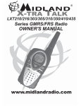
1
75-440
UHF Handheld GMRS Transceiver
User’s Manual
Copyright © 2003 by Midland Radio; all rights reserved.
75-440 User manual
In this book…
IN THIS BOOK…................................................................................................................................................. 2
INTRODUCTION .................................................................................................................................................... 4
WARNING NOTES ................................................................................................................................................. 4
FCC LICENSING INFORMATION ............................................................................................................................ 4
SAFETY ................................................................................................................................................................ 4
CONVENTIONS AND SYMBOLS IN THIS BOOK ....................................................................................................... 6
PART NAMES AND THEIR FUNCTIONS ...................................................................................................... 7
TOP ...................................................................................................................................................................... 7
FRONT .................................................................................................................................................................. 7
SIDE (LEFT AND RIGHT) ........................................................................................................................................ 8
DISPLAY............................................................................................................................................................... 8
SETUP.................................................................................................................................................................... 9
UNPACKING ......................................................................................................................................................... 9
FITTING AND REMOVING THE ANTENNA ............................................................................................................. 10
INSTALLING AND REMOVING THE BATTERY PACK .............................................................................................. 10
INSTALLING/REMOVING THE BELT CLIP .............................................................................................................. 11
CHARGING THE BATTERY PACK .......................................................................................................................... 11
BASIC OPERATIONS ....................................................................................................................................... 12
SWITCHING THE RADIO ON AND OFF ................................................................................................................ 12
ADJUSTING VOLUME .......................................................................................................................................... 12
CHANNEL SELECTION ......................................................................................................................................... 13
RECEIVING ......................................................................................................................................................... 13
MONITOR BUTTON ............................................................................................................................................. 13
TRANSMITTING .................................................................................................................................................. 14
ADJUSTING TRANSMIT POWER ........................................................................................................................... 14
SCANNING CHANNELS ........................................................................................................................................ 15
RADIO LOCK....................................................................................................................................................... 16
ADVANCED OPERATIONS ............................................................................................................................ 17
HANDSFREE TRANSMIT (VOX).......................................................................................................................... 17
PAGING CALL..................................................................................................................................................... 17
ROGER BEEP ...................................................................................................................................................... 18
KEY BEEP .......................................................................................................................................................... 18
SETTING “GROUP MODE” (CTCSS/DCS) CODES ........................................................................................... 18
BATTERY PACKS ................................................................................................................................................ 20
RADIO MAINTENANCE ........................................................................................................................................ 21
OPTIONAL ACCESSORIES ............................................................................................................................ 22
QUICK REFERENCE ....................................................................................................................................... 24
OPERATION REFERENCE ..................................................................................................................................... 24
SERVICE: ........................................................................................................................................................... 25
INDEX.................................................................................................................................................................. 26
Page.
2
75-440 User manual
LIMITED WARRANTY .................................................................................................................................... 28
Page.
3
75-440 User manual
Introduction
Congratulations. 75-440 is an advanced GMRS (General Mobile Radio Service) Professional Radio. Its
rugged design allows it to be your reliable partner even during hard working days. Its LCD as well as user
friendly controls make the 75-440 easy to use.
To extend the flexibility of the radio, a “VOX” (Voice Operated Transmit) function has been added which
allows switching the transmission just by talking in full hands free condition (with optional headset).
Transceiver’s specifications provided in 75-440 are compliant with EIA/TIA 603 and ETS 300 086, The 75440 top level design and resistance are compliant with IEC529 level IP54 and MIL STD 810 C,D,E.
Midland Radio is committed to continuous quality improvements, for this reason specifications may vary
without prior notice.
Warning notes
Every effort has been made to ensure that the information in this document is complete, accurate, and upto-date. Midland Radio assumes no responsibility for the results of errors beyond its control. The
manufacturer of this equipment also cannot guarantee that changes in the equipment made by non
authorized people will not affect the applicability of the information in it.
FCC Licensing Information
This Midland model 75-440 radio operates on GMRS frequencies which require a license from the Federal
Communications Commission (FCC) for business, personal, and recreational use. A GMRS license held
by an individual may be shared by immediate family members.
To obtain forms, call the FCC forms hotline at: 1-800-418-3676 or go to http://www.fcc.gov. Please request forms
605 and 159 which include all necessary forms and instructions.
For questions concerning licensing, contact the FCC at 1-888-CALL-FCC (1-888-225-5322), or go to
http://wireless.fcc.gov/services/personal/generalmobile .
Safety
Your 75-440 handheld transceiver has been carefully designed to give you years of safe, reliable
performance. As with all electrical equipment, however, there are a few basic precautions you should take
to avoid hurting yourself or damaging the radio:
•
Read the instructions in this handbook carefully. Be sure to save it for future reference.
•
Read and follow all warning and instruction labels on the radio itself.
•
Do not carry the transceiver by the antenna. This may damage the antenna or antenna terminal.
Grasp it by its base (not the tip!) when you need to place or remove it.
•
Do not keep the radio with the antenna very close to, or touching exposed parts of the body, while
transmitting. The radio will perform best if the microphone is 5-10 cm away from the mouth and the
radio is vertical.
Page.
4
75-440 User manual
•
Be sure the “PTT” key is not pressed when you do not need to transmit.
•
Do not operate the radio near unshielded electrical blasting caps or in an explosive atmosphere.
•
Do not transmit without the antenna fitted on the radio. Though it is provided with a protection, it
may damage the TX output final stage.
•
Respect the environment conditions. The radio is designed to be used in heavy environments,
however avoid exposing it to extremely hot or cold temperature (out of the range between –30 to
+60°C). Do not expose the transceiver to excessive vibrations as well as dusty or rainy places.
•
Never try to disassemble or service the radio by yourself (aside from the routine maintenance
described in this handbook). It will immediately void the warranty and you may cause damage
requiring extensive repair work. Always contact your local dealer for assistance.
•
Use only authorized accessories. Non original ones could seriously damage your handheld
transceiver.
•
Do Not spill liquid of any kind into your radio. If the transceiver gets wet, immediately dry it by a
soft and clean cloth.
•
Switch the radio off before you clean it. Strictly follow the directions described in the paragraph
“Care and maintenance”.
•
Handle the battery properly. Strictly follow the directions reported in “Care and maintenance”.
•
Be certain that your power source matches the rating listed for the supplied battery charger (AC
adapter). If you are not sure, check with your dealer.
•
To avoid damaging the power cable of the battery charger, do not put anything on it or place it where
it will be walked on.
This product complies with the requirements of the Council Directives 89/336/EEC and 73/23/EEC on the
approximation of the laws of the member states relating to electromagnetic compatibility and low voltage.
WARNING
Your wireless hand-held portable transceiver contains a low power transmitter.
When the Push-to-Talk (PTT) button is pressed it sends out radio frequency
(RF) signals. The device is authorized to operate at a duty factor not to exceed
50%. In August 1996, the Federal Communications Commission (FCC)
adopted RF exposure guidelines with safety levels for hand-held wireless
devices.
To maintain compliance with the FCC's RF exposure guidelins, this transmitter
and it’s antenna must maintaina a separation distance of least 2 inches (5
centimeters) from your face. Speak in a normal voice, with the antenna pointed
up and away from the face at the required separation distance. The beltclip is
for storage purposes only. DO NOT TRANSMIT WHILE USING THE BELT
CLIP. To transmit, hold the device away from your body and ensure the
antenna is at least least 2 inches (5 centimeters) from your body when
transmitting.
Page.
5
75-440 User manual
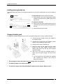
Conventions and Symbols in this Book
This symbol marks a ‘note’. Notes are hints or tips which offer additional information to help you.
, This symbol marks a ‘caution’. Cautions are special notices, which you should read and follow
carefully to avoid possible damage to your equipment and to avoid potential danger to
yourself or other people.
Key names will be highlighted in bold.
Important sentences and words are highlighted in Italic.
Page.
6
75-440 User manual
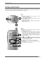
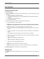
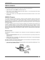
Part Names and their functions
Please have a look at the following parts description in order to familiarize yourself with the transceiver’s
main parts and controls. Numbers in brackets refer to the illustration.
Top
[1] Antenna connector. Fit the
connector (MX thread type).
2
1
antenna to this
[2] Power ON/OFF knob. Rotate this knob to turn the
transceiver on and off.
[3] Status LED. Glows in different colors to show the
radio’s current status.
3
Front
[4] Speaker. The built in speaker located in this point
emits the received sound.
4
[5] LCD display. Shows the radio’s parameters (channel
number etc.). Icon and symbols are further explained
in the paragraph “Display”. Whenever any key or
button is pressed, the display is automatically backlit
for few seconds.
[6]
8
(Up) and
(down) buttons. For scrolling
forward and backward through the channel list and
for changing function values.
5
[7] “FUNC” button. Allows changing function values.
6
[8] Microphone. Your voice is
microphone located in this place
detected
by
the
Page.
7
7
75-440 User manual
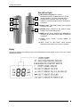
Side (left and right)
12
14
11
9
[9] Microphone connector. For remote
speaker/microphone, headsets for VOX use and
other accessories. It must be protected with the
supplied rubber cap when not in use. For the
related pin connections please see to “Microphone
connection”.
[10] Battery pack. This NiMH battery pack supplies
energy to your radio.
13
10
[11] Release button (located on the battery’s body).
Allows to remove the battery pack
[12] MON (monitor) button. Enables the loudspeaker for
monitoring of the tuned channel when CTCSS/DCS
is enabled.
[13] “CALL” button. Sends a paging “CALL” (if
enabled)
[14] “PTT” (Push To Talk) button. When pressed
switches the transceiver from receive to transmit.
Display
This section explains the meaning of the various indications that may appear on the LCD of your 75-440
handheld transceiver:
Page.
8
75-440 User manual
Setup
Unpacking
The following items are in the package:
(a) Transceiver’s main body
(b) Flexible antenna
(c) Battery pack NiMH 1,300 mA/h
(d) Belt clip
(e) Users guide (this book!)
If something is missing please promptly advise your supplier.
Page.
9
75-440 User manual
Fitting and removing the Antenna
To fit the antenna:
1) Locate the antenna terminal (thread MX type) on transceiver’s top.
2) Hold the transceiver with one hand and the base (the thicker part) of the antenna with the other.
3) Attach the included rubber duck antenna to the antenna terminal by turning it clockwise until it is firmly
locked. Do not overtighten.
To remove the antenna do the same described procedure. At step 3 turn the antenna base
counterclockwise.
, Always have the antenna attached to the radio. You can not communicate without it.
Transmitting without the antenna will damage the TX output final stage. For the same reason
use only the supplied antenna.
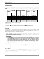
Installing and removing the battery pack
To install the battery pack:
SLIDE DOWN
1
1) Hold the transceiver’s body with one hand and the battery
pack with the other. Put the bottom edge of the battery
pack onto the bottom of the transceiver.
2) Gently push the battery pack toward the transceiver’s
body until the battery latches.
2
PUSH DOWN
To remove the battery pack:
1
PUSH DOWN
1) Press the battery release button located in the top of the
battery pack.
2) Keep the button pressed and gently pull the battery pack
away from the transceivers body.
2
LIFT UP
3) Remove the battery pack by separating it from the
transceiver’s body.
Page. 10
75-440 User manual
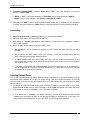
Installing/removing the belt clip
The supplied belt clip allows you to hang the transceiver on your belt or jacket when you are not using the
radio.
1
To fit the belt clip onto the transceiver’s body:
SLIDE DOWN
1) Gently slide the clip into the appropriate guides
located on the transceiver’s battery pack until it
firmly locks.
To remove the belt clip:
PUSH
LIFT UP
3
2
2) Gently move the latch located between the top
of the belt clip and the battery pack towards the
belt clip
3) Slide the belt clip off the radio.
Charging the battery pack
To charge the supplied battery pack you have to setup the charger and connect the radio as follows:
1) Connect the jack coming from the AC adapter to
the cradle’s socket.
3) Connect the AC plug of the AC adapter’s power
cable into a grounded AC power outlet.
4) Ensure that the radio is switched off.
5) Insert the radio into the cradle with the keypad
toward you (the three metallic contacts of the
battery pack must touch with the three contacts
inside the cradle).
6) Wait 10-12 hours with the standard charger 2
hours with the rapid charger and remove the
radio..
Do not remove the radio before the specified
time, otherwise the battery’s duty could be
temporarily reduced.
, Do not forget to remove the radio from slow charger after 10 to 12 hours.
, The battery charger is for indoor use only.
, For the next charges, best duty and battery life please see the chapter “Battery Packs”.
Page. 11
75-440 User manual
Basic Operations
Switching the radio ON and OFF
To switch the radio on:
1) Rotate the “PWR/VOL” knob clockwise until the radio is switched on. The CPU will start an auto test
as follows:
•
•
•
LED will glow GREEN, then RED and turn OFF.
LCD will display all segments and icons. The letters "PS"("PASS") will be displayed followed by a
long beep.
LCD will display the last operating mode.
The self-test goes very fast.
2) After the auto test has been carried out LCD will show the following data:
•
The channel number. (2 numeric characters).
NOTE: About 0.5 second after you select a new channel or change operation mode, the last status
is automatically saved. When the Radio is turned on, the most recently used channel is displayed.
NOTE: the following icons will be displayed depending on the operating mode.
• The currently selected TX output power: LOW for low or nothing for high in the lower left corner of
the LCD.
• A small “•” is displayed in the lower right corner of the LCD if the channel is in the SCAN list. (if
enabled)
• A “P” is displayed to show that the channel is in the priority Scan list. ( if enabled)
• “SAT” in the upper left corner indicates that the channel is a GROUP CHANNEL (for CTCSS or
DCS tone if enabled).
• “Battery” icon when visible indicates battery is low.
• “VOX” is displayed when “VOX” function is enabled.
• A “Key” icon to indicate that the keypad is locked.
NOTE: When “VOX” is enabled, ““PTT”” button is not working.
NOTE: When keypad is locked; only “PTT” button is enabled (with exception of VOX enabled).
To switch the radio off, rotate the PWR/VOL knob counterclockwise.
Adjusting volume
The PWR/VOL knob is used to adjust the RX volume: turn it clockwise to increase or counterclockwise to
reduce it.
Page. 12
75-440 User manual
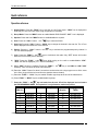
Channel selection
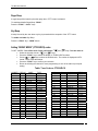
Each channel is identified by 2 numeric digits. The FCC assigned GMRS channel frequencies are
programmed into your radio as shown in the table below. Channels 1 through 7 are shared with FRS
radios.
Channel
Freq. MHz.
Channel
Freq. MHz.
(FRS Ch.)
Channel
Freq. MHz.
(Duplex)
Tx/Rx
1
2
462.5625
462.5875
8
9
462.5750
462.6250
16
17
467/462.5750
467/462.6250
3
462.6125
10 *
462.6750
18
467/462.6750
4
462.6375
11
462.5500
19
467/462.5500
5
462.6625
12
462.6000
20
467/462.6000
6
462.6875
13
462.6500
21
467/462.6500
7
462.7125
14
462.7000
22
467/462.7000
15
462.7250
23
467/462.7250
* GMRS Emergency Channel (10) 462.675 MHz.
To select a channel:
1) Press the
key to increase the channel number or the
key to decrease it.
Receiving
Your radio can be programmed to work, channel by channel, in “Open traffic” or “GROUP MODE
(CTCSS/DCS)”. Group mode prevents other users of a channel from being heard on your radio. See
“Setting Group Mode Codes” for programming instructions.
•
OPEN TRAFFIC: in this case you will hear all communication which will be transmitted on the
selected channel. When a message is received your squelch will un-mute, you will see the status LED
glowing green and you will hear the message.
•
GROUP MODE:
• CTCSS/DCS (Continuous Tone Code Squelch System / Digital Coded Squelch): are systems
which use particular TX signaling as an access “key” to work a repeater (encoder) or to unlock the
party’s signaling sensitive squelch. This last condition allows more radio networks to share the
same frequency. In this case you will receive only messages coming from parties sending a
proper TX signaling. During “CTCSS/DCS” operation, the radio may be set-up so that the
appropriate CTCSS/DCS decoder enables the speaker.
, CTCSS/DCS If more than one station is transmitting at the same time, this will cause
interference! Do not transmit if the status LED is glowing. Wait until the channel is clear before
transmitting.
Monitor Button
The Monitor button can enable or disable “GROUP MODE (CTCSS/DCS)” if programmed for that channel.
1) To enable “GROUP MODE”. Press and release the“MON” button: “SAT” icon is displayed. A Sub
Audible Tone mutes your speaker.
Page. 13
75-440 User manual
2) To Disable “GROUP MODE”. Press the “MON” button: “SAT” icon is not displayed. You are now
working in “Open Traffic”.
NOTE: if “SAT” icon is never displayed, “CTCSS/DCS” tone is not programmed. “GROUP
MODE” function is not available. See ‘Setting “Group Mode” codes’.
3) Press and Hold “MON” button for three seconds, internal squelch will be disabled and your speaker is
un-muted. Press and release the “MON” button to restore the squelch to normal operating condition.
Transmitting
1) Ensure that the channel is not busy otherwise you will create interference.
2) Press the “PTT” button, the status LED will glow red.
3) Start talking at a normal voice level at approximately 2.5 inches from the microphone (keep the
“PTT” button pressed).
4) When you have finished talking, release the “PTT” button.
Do not shout! It will not increase the distance you can transmit, but rather will make you heard
distorted.
Do not release the “PTT” button before your message is over or start talking before pressing
“PTT”, otherwise your message will be “chopped”.
A GMRS handheld radio does not normally allow you to talk and receive simultaneously, for this
reason make your messages short. When you are talking the other parties can not use the channel!
Use common sense.
Your radio is programmed with a timeout timer which will automatically turn off the transmitter if
you talk longer than 90 seconds. In this case release the “PTT” and wait for few seconds, the radio
TX features will be automatically restored.
Adjusting Transmit Power
Your 75-440 can transmit with two power levels according to the distance of your party’s station(s). We do
recommend, when possible, to use the Low power setting. This will increase the battery life and will
reduce the risk of interference with other stations not in your radio network that may be sharing the same
channel with you.
1) To change the channel's Power Output level from high (2 Watts) to Low (0.5 Watt), or vice versa,
Press and Hold “FUNC” key for about 2 seconds. A small "LOW" will appear in the lower left corner
of the display to indicate “Low Power”. High Power has no indicator.
If the battery icon is "blinking" (Low Battery indication), the Unit will automatically switch to Low
Power when transmitting in order to help prolong the Battery's operational life. In this case, two
short beeps will be heard when you press the “PTT” key before the radio transmits.
Page. 14
75-440 User manual
Scanning channels
Your 75-440 has three types of scanning available. The most used is Normal Scan. This allows you to
scan all the channels you have designated in your scan list (see Creating Scan List). The next is scan with
a Priority channel (channel 1). This scan allows you to monitor channel 1 more often than the other
channels while scanning (for this scan to work properly you must have at least 6 channels in the scan list).
The third scan type is Dual Watch. This allows you to scan the priority channel and a channel of your
choice. You must have more than one channel programmed in the scan list in order for your 75-440 to
scan them. The advanced scan function of the radio allows optionally looking for carrier or carrier with
“CTCSS” or “DCS.”
Activating, Deactivating Normal Scan
key. You will see the channel numbers cycling continuously.
1) Press the “CALL” button +
2) To stop scanning press the “CALL” button +
key.
, If when deactivating Normal scan you press the “CALL” button +
key, the radio will be in
key to deactivate the Normal scan the radio will
Priority scan. If you press the “CALL” button +
now be in Dual Watch (as described later). In this case to deactivate both scans you must first press
the “CALL” button +
then press the correct buttons “CALL” button +
key.
Reviewing the Scan-List.
1) Scroll the channel list, channels which show the “•“ icon, are in the “SCAN” list.
2) Select the channel, which is to be added or deleted from the “Scan” list.
Adding and removing channels from the Scan list is not available during scanning.
3) Press “CALL” + “MON” button, the “•” icon will appear or disappear. (See step 1 above.)
NOTE: If the Scan List has no channels, a low tone (error beep) will be heard when the “CALL”
+
key is pressed, no channel will be scrolled in the display. At least two channels must be in
the Scan List for the Unit to be put in the SCAN Mode.
When a signal is received on a channel, the radio will stop scanning and the speaker will become
un-muted. When the activity on that channel ceases, the unit will automatically resume scanning.
If CTCSS/DCS have been previously programmed, the scanning will stop only if the received
carrier has the correct CTCSS or DCS code for that channel.
If “PTT” is pressed during scanning, the radio will transmit on the first vacant channel. In case of no
activity, the Unit will automatically resume scanning.
Selecting a Priority Channel
One channel can be assigned as a “Priority Channel”. The scanning will look back at the priority channel
most frequently. Channel 1 is factory set as the priority channel.
Current radio version only allows for PC programming of another priority channel.
Using a Priority Channel
1) To activate Priority channel, press the “CALL” +
right corner of the display to confirm your selection.
Activate scan by pressing “Call” +
channels in the scan list.)
key. A "P" will be displayed in the lower
key. . (For this scan to work properly you must have at least 6
Page. 15
75-440 User manual
2) Deactivate scan by pressing “Call” +
stop the scan.
to remove the Priority channel then press “Call” +
to
Selecting Dual Watch
key to activate the Priority
1. Choose the second channel you wish to use. Press the “CALL” +
channel. A "P" will be displayed in the lower right corner of the display to confirm your selection.
2. The radio will scan the chosen channel and the priority channel (usually channel 1).
Radio lock
Your 75-440 has been provided with a security function, which protects it against accidental activation of
commands. You can lock the radio as follows:
To lock the radio:
1) Press the “FUNC” key +
key. The display will show the key icon.
To unlock the radio:
1) Press the “FUNC” key +
key.
When the radio is locked only the “PTT” button is enabled.
Page. 16
75-440 User manual
Advanced Operations
In this section we’ll describe some advanced operation which you can do with your handheld transceiver:
Handsfree Transmit (VOX)
VOX (Voice Operated Transmit) is an automatic system, which allows you to automatically switch the
transmission in hands free mode just by speaking in the built-in microphone of a headset (not provided
with the unit). Please ensure that the handset is suitable for your transceiver as reported in the paragraph
“Microphone connection”.
1) Connect the optional headset with built-in microphone to the microphone connector located on the
transceiver’s side. Be sure the headset is equipped for “VOX” operation.
2) To activate “VOX”: Turn the radio off. Press and hold the “FUNC” +
“VOX” icon will be displayed.
keys turn the radio on.
3) Ensure that the headset’s built-in microphone is located close to the side of your mouth.
key to adjust the “VOX” sensitivity in order to ensure a stable
4) Press the “FUNC” key +
transmission when speaking with a normal voice level.
“VOX” icon will flash when LOW sensitivity is selected and on steady when HIGH sensitivity is
selected.
, We recommend setting the “VOX” for minimum sensitivity. Sensitivity set too high could cause
accidental transmissions, especially in high noise environments.
“PTT” button is disabled during VOX.
5) To DEACTIVATE “VOX”: Turn off the radio. Press and hold the “FUNC” +
radio on. The “VOX” icon will no longer be displayed. The “VOX” is now off.
keys. Turn the
Paging Call
User can alert radios of his fleet by pressing the “CALL” button. The other parties will hear a ringer type
sound.
To send an automatic “CALL”:
1) Press the “CALL” key for about 2-sec. to alert all the radios in your fleet.
2) A ringer type sound will advise the other parties about the incoming message.
3) Press the “PTT” and Speak with a normal voice level to send the message.
Page. 17
75-440 User manual
Roger Beep
A roger beep will be heard by the other party when “PTT” button is released.
To enable or disable Roger Beep “FUNC”:
Press the "FUNC" + CALL” keys.
Key Beep
A beep is heard by the user when any key is pressed with the exception of the “PTT” button.
To enable or disable Key Beep:
Press the “FUNC” key + “MON” button.
Setting “GROUP MODE” (CTCSS/DCS) codes
To SET CODES”: Turn off the radio. Press and hold the “
and
keys. Turn the radio on.
•
•
and
keys.
Select the channel with the “
Press the “FUNC” key to switch the display to TX/RX CODE numbers.
•
or
keys to select the desired code. The number is displayed in HEX
Press
format. Refer to the table below.
Press the “FUNC” key to confirm your selection.
Return to selecting the channel for more programming or turn off the radio to quit copde
setting.
•
•
Table: Tone Code vs CTCSS/DCS
NUMBER DISPLAY CODE
0
NO TONE
0
1
1
67.0 Hz
2
2
71.9 Hz
3
74.4 Hz
3
4
4
77.0 Hz
5
5
79.7 Hz
6
6
82.5 Hz
7
7
85.4 Hz
8
8
88.5 Hz
9
9
91.5 Hz
10
A
94.8 Hz
11
b
97.4 Hz
12
C
100 Hz
13
d
103.5 Hz
14
E
107.2 Hz
15
F
110.9 Hz
16
10
114.8 Hz
17
11
118.8 Hz
18
12
123.0 Hz
19
13
127.3 Hz
20
14
131.8 Hz
21
15
135.5 Hz
22
16
141.3 Hz
TYPE
NONE
CTCSS
CTCSS
CTCSS
CTCSS
CTCSS
CTCSS
CTCSS
CTCSS
CTCSS
CTCSS
CTCSS
CTCSS
CTCSS
CTCSS
CTCSS
CTCSS
CTCSS
CTCSS
CTCSS
CTCSS
CTCSS
CTCSS
23
24
25
26
27
28
29
30
31
32
33
34
35
36
37
38
39
40
41
42
43
44
45
46
17
18
19
1A
1b
1C
1d
IE
IF
20
21
22
23
24
25
26
27
28
29
2A
2b
2C
2d
2E
146.2 Hz
151.4 Hz
156.7 Hz
162.2 Hz
167.9 Hz
173.8 Hz
179.9 Hz
186.2 Hz
192.8 Hz
203.5 Hz
210.7 Hz
218.1 Hz
225.7 Hz
233.6 Hz
241.8 Hz
250.3 Hz
69.3 Hz
159.8 Hz
165.5 Hz
171.3 Hz
177.3 Hz
183.5 Hz
189.9 Hz
196.6 Hz
CTCSS
CTCSS
CTCSS
CTCSS
CTCSS
CTCSS
CTCSS
CTCSS
CTCSS
CTCSS
CTCSS
CTCSS
CTCSS
CTCSS
CTCSS
CTCSS
CTCSS
CTCSS
CTCSS
CTCSS
CTCSS
CTCSS
CTCSS
CTCSS
Page. 18
75-440 User manual
47
48
49
50
51
52
53
54
55
56
57
58
59
60
61
62
63
64
65
66
67
68
69
70
71
72
73
74
75
76
77
78
79
80
81
82
83
84
85
86
87
88
89
90
91
92
93
94
95
96
97
98
99
100
101
2F
30
31
32
33
34
35
36
37
38
39
3A
3b
3C
3d
3E
3F
40
41
42
43
44
45
46
47
48
49
4A
4b
4C
4d
4E
4F
50
51
52
53
54
55
56
57
58
59
5A
5b
5C
5d
5E
5F
60
61
62
63
64
65
199.5 Hz
206.5 Hz
229.1 Hz
254.1 Hz
023
025
026
031
032
036
043
047
051
053
054
065
071
072
073
074
114
115
116
122
125
131
132
134
143
145
152
155
156
162
165
172
174
205
212
223
225
226
243
244
245
246
251
252
255
261
263
265
266
271
274
CTCSS
CTCSS
CTCSS
CTCSS
DCS
DCS
DCS
DCS
DCS
DCS
DCS
DCS
DCS
DCS
DCS
DCS
DCS
DCS
DCS
DCS
DCS
DCS
DCS
DCS
DCS
DCS
DCS
DCS
DCS
DCS
DCS
DCS
DCS
DCS
DCS
DCS
DCS
DCS
DCS
DCS
DCS
DCS
DCS
DCS
DCS
DCS
DCS
DCS
DCS
DCS
DCS
DCS
DCS
DCS
DCS
102
103
104
105
106
107
108
109
110
111
112
113
114
115
116
117
118
119
120
121
122
123
124
125
126
127
128
129
130
131
132
133
134
135
136
137
138
139
140
141
142
143
144
145
146
147
148
149
150
151
152
153
154
66
67
68
69
6A
6b
6C
6d
6E
6F
70
71
72
73
74
75
76
77
78
79
7A
7b
7C
7d
7E
7F
80
81
82
83
84
85
86
87
88
89
8A
8b
8C
8d
8E
8F
90
91
92
93
94
95
96
97
98
99
9A
306
311
315
325
331
332
343
346
351
356
364
365
371
411
412
413
423
431
432
445
446
452
454
455
462
464
465
466
503
506
516
523
526
532
546
565
606
612
624
627
631
632
654
662
664
703
712
723
731
732
734
743
754
DCS
DCS
DCS
DCS
DCS
DCS
DCS
DCS
DCS
DCS
DCS
DCS
DCS
DCS
DCS
DCS
DCS
DCS
DCS
DCS
DCS
DCS
DCS
DCS
DCS
DCS
DCS
DCS
DCS
DCS
DCS
DCS
DCS
DCS
DCS
DCS
DCS
DCS
DCS
DCS
DCS
DCS
DCS
DCS
DCS
DCS
DCS
DCS
DCS
DCS
DCS
DCS
DCS
Page. 19
75-440 User manual
Battery Packs
Information on rechargeable batteries
• When the battery pack is new it will not provide 100% of its efficiency. To reach the full battery run
time you have to “run-in” the battery with at least 3-4 deep charging/discharging cycles. After that
it will reach its maximum capacity. Please see “Proper charging of battery packs” for further
details.
• When you properly use the battery pack, you will obtain about 400 charge/discharge cycles (300
with the optional rapid charger). The battery “run time” will progressively reduce after 2/3 of its life
(approx.).
• Rechargeable battery packs lose their charge with time if left unused (self-discharge), this is
normal. A NiMH (Nickel Metal Hydride) battery can reduce 10 to 20% of its stored energy in few
days.
Proper charging of battery packs
1) Ensure that the radio is switched off,
5) Insert the radio into the cradle as explained in the paragraph “Charging the battery pack”
6) Wait the necessary time to provide a full charge. If the pack isn’t completely discharged you will need
less than 8 hours.
, Do not overcharge the battery: always remember to remove the radio after the necessary time.
, The battery charger is for indoor use only.
When possible, charge the battery only when it is fully discharged or, at least, you have used it for
the major part of the day, otherwise the battery’s “run time” could be temporarily reduced.
Do not remove the radio before the necessary time, otherwise the battery’s “run time” could be
temporarily reduced.
• When possible charge battery packs only when they are completely discharged, i.e. when the
battery icon has no bars inside.
• Do not remove the battery from the charger before the necessary time to provide a full charge.
• Provide at least two deep charge/discharge cycles per month.
Warnings for battery and chargers use
Please use these cautions to avoid damaging battery packs or the transceiver:
, Before using the battery charger carefully read any related warning or caution.
, Do not short battery terminals: this may cause fire, burns or explosions.
, Never dispose batteries into fire they may explode causing fire, burns or explosions. Strictly
follow any disposal regulation of your Country.
Page. 20
75-440 User manual
, Use only authorized batteries and chargers. The use of non-authorized accessories may cause
burns, fire or explosions causing serious damages to the radio/battery or serious injuries to
people.
, Battery chargers are for indoor use only.
, Be certain that your power source matches the rating listed for the supplied battery charger
(AC Adapter). If you are not sure, check with your dealer or with your local power company.
, To avoid damaging the power cable of the battery charger, do not put anything on it or place it
where it will be walked on. Insert the plug in socket provided with earth connection.
, Avoid strong shocks. Do not use the charger if it received a strong shock, has fallen down or it
appears damaged; immediately contact an authorized service station.
, Never try to disassemble or service the charger by yourself. Always contact your local dealer
for assistance.
, To reduce the risk of electric shocks disconnect the plug before providing any cleaning or
maintenance. Grasp the plug (not the cable) to remove the plug from the socket. The use of
non-suitable extension can cause fire or electric shocks.
, Do not expose batteries directly to temperatures below -20°C (-4°F) or greater than 35°C (95°F)
during their use and do not charge them outside the range of +5 to +55°C.
Radio maintenance
Cleaning battery packs
Wipe the battery contacts with a clean and lint free cloth to remove dirt, grease or any other material that
may prevent a good electrical contact. If contacts are very dirty you can also wipe them using a soft pencil
rubber (not hard erasers for ink!). If you feel that battery contacts aren’t still working properly, please
contact your authorized dealer.
, Do not use liquid, alcohol or aerosol cleaners.
Cleaning the radio
•
Wipe the radio with a clean and lint free cloth to remove dust. If it is very dirty, you can use a damp
(slightly moistened with water) cloth.
, Do not use liquid, alcohol or aerosol cleaners.
If you normally use your radio in dusty or hard environments, we do recommend using the optional
carrying case. Please see “Optional accessories”.
Connectors
When the connectors are not being used, they should be fitted with the supplied cover caps.
, Only suitable accessories must be connected to the related connectors.
Page. 21
75-440 User manual
Optional accessories
These optional accessories can be used to improve the transceiver’s performances:
•
Spare battery pack number 81B02. It extends the duty time.
•
Rapid charger number 18-388. Recharges the battery packs in 1 hour and provides trickle charge
when they reached their full charge.
•
Carrying case. Protects your radio against small shocks and scratches the best for use in hard
environments.
WARNING, RF exposure
Your wireless hand-held portable transceiver contains a low power transmitter. When the Push-to-Talk
(PTT) button is pressed sends out radio frequency (RF) signals. The device is authorized to operate at a
duty cycle factor not to exceed 50%. In august 1996, the Federal Communications Commissions (FCC)
adopted RF exposure guidelines with safety levels for hand-held wireless devices. The FCC has issued
the following warning,
To maintain compliance with the FCC’s RF exposure guidelines, this transmitter and its antenna must
maintain a separation distance of at least 2 inches (5 centimeters) from your face. Speak in a normal
voice, with the antenna pointed up and away from the head at the required separation distance. The belt
clip is for storage only. DO NOT TRANSMIT WHILE USING THE BELT CLIP. To transmit, hold the device
away from your body and ensure the antenna is at least 2 inches (5 centimeters) from your body when
transmitting.
Microphone connector
The microphone connector is designed for the connection of two basic accessories (not supplied as
standard):
•
External speaker/microphone: Allows you to use the radio secured to your belt by means of the
supplied belt clip.
•
Headset with built-in microphone: Will additionally add the VOX facility, For further details please
see “Hands free transmission (VOX)”.
Any kind of accessory for the above stated purposes can be connected to the microphone connector,
provided that they meet the following requirements:
•
Jack connectors for Speaker (SPK) and Microphone (MIC) must be respectively standard type 3.5 mm
and 2.5 mm. and connected as follows:
MicGND
MicGND
MIC
MIC
SPK
SPK
Spk
Spk GND
GND
Page. 22
75-440 User manual
•
The suggested speaker input impedance is 8 Ohms
•
The microphone should be condenser low-impedance type.
•
All accessories should be hi-quality suitable for professional use.
, Please do not connect any accessory that you are not sure meet the above stated
requirements. You could cause serious damage to your radio. In if your not sure please
contact your authorized dealer.
Page. 23
75-440 User manual
Quick reference
Operation reference
1) Output Power: Press the “FUNC” key to set High or Low Power output. “LOW” icon is displayed to
show that you set Low Power output. (high output has no indication)
2) Group Mode: Press the “MON” button to enable/disable GROUP MODE. “SAT” icon is displayed.
3) Squelch: Press and Hold “MON” button to enable/disable the squelch.
4) Scan: Press the “CALL” button + the
key to enter the SCAN.
5) Scan List: Press the “CALL” button + “MON” key to change the channel in the scan list. The “•”icon
will be displayed if the channel is in the scan list.
6) Priority: Press the “CALL” button + the
“P” icon will be displayed.
key to activate the programmed priority channel. A
keys to lock/unlock the radio. Only “PTT” button will function
7) Lock: Press the “FUNC” + the
when the unit is locked (VOX is disabled).
keys while turning on the radio to enable/disable “VOX”.
8) “VOX” Press the “FUNC” + the
“VOX” icon will be displayed. (“PTT” button is disabled)
9) When “VOX” function is enabled, Press the “FUNC” + the
sensitivity. VOX icon blinks to show LOW sensitivity.
key to set HIGH or LOW “VOX”
10) Press the “CALL” Button for about 2 seconds to send an alert with a ringer type tone to all the users
in the fleet. (ringer will also be heard from the speaker when activated)
11) Press the “FUNC” + “CALL” keys to enable / disable roger beep at the end of the transmission.
12) Press “FUNC” + “MON” keys to enable/disable key beep.
, Press the “FUNC” + the
key and switch on the unit. UP will be displayed and unit enters
the PROGRAMMING MODE. This operation is only allowed to authorized person.
Channel
Freq. MHz.
Channel
Freq. MHz.
(FRS Ch.)
Channel
Freq. MHz.
(Duplex)
Tx/Rx
1
2
462.5625
462.5875
8
9
462.5750
462.6250
16
17
467/462.5750
467/462.6250
3
462.6125
10 *
462.6750
18
467/462.6750
4
462.6375
11
462.5500
19
467/462.5500
5
462.6625
12
462.6000
20
467/462.6000
6
462.6875
13
462.6500
21
467/462.6500
7
462.7125
14
462.7000
22
467/462.7000
462.7250
23
467/462.7250
15
* GMRS Emergency Channel (10) 462.675 MHz.
Page. 24
75-440 User manual
SERVICE:
If it ever becomes necessary to return your unit for service:
1.
Pack the unit in its original box and packing.
2.
Pack the original box in a suitable shipping carton. Improper packing will result in damage during shipment.
3.
Include a photocopy of the bill of sale showing the date of purchase.
4.
Include a brief description of the problem you are having.
5.
Include a DAYTIME telephone number.
6.
Include a money order or Visa or Master Card credit card number for $7.50 to cover shipping and handling. No
personal checks please.
7.
You do not need to return accessory unless they maybe directly related to the problem.
8.
This information must be included before Warranty Service can be considered. Failure to include these items
will delay the repair of the radio until these items are received.
Ship to:
Service
Midland Radio
1120 Clay St.
North Kansas City, Mo. 64116
Page. 25
75-440 User manual
Index
A
Adjusting
Transmission Power
Volume
Antenna
fitting/removing
14
13
10
B
Battery charger
rapid (optional)
standard
Battery pack
Charging
Battery packs
cleaning
Information on rechargeable batteries
Proper changing
Warnings for battery and chargers use
Belt clip
22
11
11
21
20
20
20
11
C
Carrying case
Channel selection
Charger
Cleaning the radio
Connectors
Conventions and Symbols
22
13
see Battery charger
21
21
6
D
Display
8
H
Handsfree transmission (VOX)
17
K
KEY BEEP
18
M
Microphone connector
22
O
Optional accessories
Carrying case
Rapid charger
Spare battery pack
Output power
Adjusting
22
22
22
22
14
Page. 26
75-440 User manual
P
PAGING
Power
button
ON/OFF
TX output adjustment
17
12
12
14
Q
Quick reference
Operation resume
24
24
R
Radio lock
Radio maintenance
Rapid charger
Reception
ROGER BEEP
16
21
22
13, 14
18
S
Safety
Scanning channels
Setup
Battery pack
Belt clip
Charging the battery pack
Fitting antenna
Package contents
Unpacking
Switching the radio ON/OFF
4
15
10
11
11
10
9
9
12
T
Transmission
Transmission Power
14
14
V
VOX
17
W
Warning notes
Warnings for battery and chargers use
4
20
Page. 27
75-440 User manual
LIMITED WARRANTY
Midland Radio Corporation will repair or replace, at its option without charge, any Midland FRS or GMRS
transceiver which fails due to a defect in material or workmanship within ONE YEAR following the initial consumer
purchase.
This warranty does not include any carrying cases, earphones, or antennas, which may be a part of or
included with the warranted product.
Performance of any obligation under this warranty may be obtained by returning the warranted product,
freight prepaid, along with proof of purchase date, to Midland Radio, Warranty Service Department, 1120 Clay St.,
North Kansas City, Missouri 64116, or to any “Midland Authorized Warranty Service Station,” or to the place of
purchase (if a participating dealer).
Warranty information and the location of the nearest “Midland Authorized Warranty Service Station,” may
be obtained by writing Midland Radio, Warranty Service Department at the above address.
This warranty gives you specific legal rights, and you may also have other rights which vary from state to
state.
Note: The above warranty applies only to merchandise purchased in the United States of America or any of the
territories or possessions thereof, or from a U.S. Military exchange.
Midland Radio Corporation
1120 Clay St.
North Kansas City, Mo. 64116
Printed in Thailand
E-mail: [email protected]
URL: www.midlandradio.com
Page. 28