1
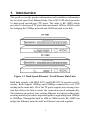
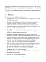
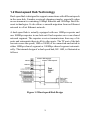
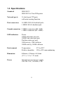
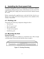
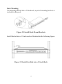
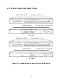
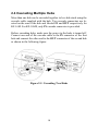
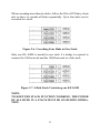
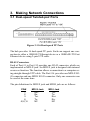
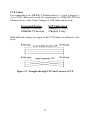
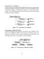
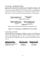
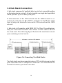
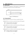
Installation Guide
16-port Dual-speed
Ethernet / Fast Ethernet Hub
KF-16M, KF-16MS
P/N:750-0105-001
DOC.980301-KF16M/16MS-K
Ó 1998 KTI Networks Inc. All rights reserved. No part of this documentation may be reproduced in any form or by any means or used to
make any directive work (such as translation or transformation) without
permission from KTI Networks Inc.
KTI Networks Inc. reserves the right to revise this documentation and to
make changes in content from time to time without obligation on the
part of KTI Networks Inc. to provide notification of such revision or
change.
For more information, contact:
United States
International
KTI Networks Inc.
P.O. BOX 631008
Houston, Texas 77263-1008
Phone:
Fax:
BBS:
E-mail:
WWW:
713-2663891
713-2663893
713-2663015
[email protected]
http://www.ktinet.com/
Fax:
BBS:
E-mail:
WWW:
886-2-26983873
886-2-26983913
[email protected]
http://www.ktinet.com/
16-port Dual-speed
Ethernet / Fast Ethernet Hub
Installation Guide
DOC.980302-KF16M/16MS-NK
P/N: 750-0105-002
The information contained in this document is subject to change without prior notice.
Copyright Ó KTI. All Rights Reserved.
TRADEMARKS
Ethernet is a registered trademark of Xerox Corp.
WARNING:
This equipment has been tested and found to comply with the limits for a Class A digital device,
pursuant to Part 15 of the FCC Rules. These limits are designed to provide reasonable protection
against harmful interference when the equipment is operated in a commercial environment. This equipment generates, uses, and can radiate radio frequency energy and if not installed and used in accordance with the instruction manual may cause harmful interference in which case the user will be required to correct the interference at his own expense.
NOTICE:
(1) The changes or modifications not expressively approved by the party responsible for
compliance could void the users authority to operate the equipment.
(2) Shielded interface cables and AC power cord, if any, must be used in order to comply with the
emission limits.
CISPR A COMPLIANCE:
This device complies with EMC directive of the European Community and meets or exceeds the following technical standard.
EN 55022 - Limits and Methods of Measurement of Radio Interference Characteristics of Information
Technology Equipment. This device complies with CISPR Class A.
WARNING: This is a Class A product. In a domestic environment this product may cause radio interference in which case the user may be required to take adequate measures.
CE NOTICE
Marking by the symbol CE indicates compliance of this equipment to the EMC directive of the
European Community. Such marking is indicative that this equipment meets or exceeds the following
technical standards:
EN 55022: Limits and Methods of Measurement of Radio Interference characteristics of Information
Technology Equipment.
EN 50082/1:Generic Immunity Standard -Part 1: Domestic Commercial and Light Industry.
EN 60555-2: Disturbances in supply systems caused by household appliances and similar electrical equipment
- Part 2: Harmonics.
Table of Contents
1.
Introduction ............................................................................... 1
1.1
1.2
1.3
Features .................................................................................................................. 2
Dual-speed Hub Technology ................................................................................. 3
Specifications ......................................................................................................... 5
2.
Installing the Dual-speed Hub .................................................. 6
2.1
2.2
2.3
2.4
Packing List ............................................................................................................ 6
Mounting the Hub .................................................................................................. 6
Front Panel and Rear Panel .................................................................................... 8
Cascading Multiple Hubs .................................................................................... 10
3.
Making Network Connections ................................................ 12
3.1
3.2
Dual-speed Twisted-pair Ports ............................................................................. 12
Hub Stack Connection ......................................................................................... 16
4.
LED Indicators ........................................................................ 17
4.1
4.2
LED Panel ............................................................................................................ 17
Interpretation ........................................................................................................ 17
Figures
1-1
1-2
1-3
2-1
2-2
2-3
2-4
2-5
2-6
2-7
3-1
3-2
3-3
3-4
3-5
3-6
3-14
4-1
Dual-speed Ethernet / Fast Ethernet Hub Unit ...................................................... 1
Dual-speed Hub Design ......................................................................................... 3
Dual-speed Hub with Built-in 10/100 Switch ....................................................... 4
Desktop Mounting ................................................................................................. 6
Install Rack Mount Brackets ................................................................................. 7
Install the Hub into a 19-inch Rack ....................................................................... 7
Components on the Front and Rear Panel ............................................................. 8
Cascading Two Hubs ........................................................................................... 10
Cascading Four Hubs in One Stack ..................................................................... 11
A Hub Stack Containing one KF-16MS .............................................................. 11
Dual-speed TP Ports ............................................................................................. 12
Straight-through UTP and Crossover UTP .......................................................... 13
Connecting to Computers .................................................................................... 14
Connecting to 10BASE-T Hubs .......................................................................... 14
Connecting to a 100BASE-TX Class II Hub ....................................................... 15
Connecting Two Hub Stacks ............................................................................... 16
Connecting Two Hub Stacks ............................................................................... 16
LED Indicators ..................................................................................................... 17
1. Introduction
This guide covers the product information and installation information
for two dual speed Fast Ethernet hubs. One is KF-16M which provides
16 dual-speed twisted-pair (TP) ports. The other is KF-16MS which
provides 16 dual-speed TP ports and one internal 10M-to-100M switch
for bridging the 10Mbps network and 100M network in the hub.
Figure 1-1 Dual-Speed Ethernet / Fast Ethernet Hub Units
Both hubs comply with IEEE 802.3 and IEEE 802.3u repeater specifications. Both support 10Mbps and 100Mbps connectivity over UTP
cabling in the same hub. All of the TP ports support auto-sensing function that allows the hub to detect the connection speed automatically.
This features can protect your existing Ethernet investment without any
rewiring and also provides a migration path for upgrading from 10Mbps
to 100Mbps. Through the built-in 10M-to-100M switch, KF-16MS can
bridge the Ethernet network and Fast Ethernet network together.
1
Both hubs also feature cascade connectors (two for KF-16M, one for
KF-16MS) on the rear for cascading one hub to another in a hub stack.
Up to four hubs can be cascaded in one stack. A hub stack can be treated
as a single hub which gives a total of 64 dual-speed TP ports with only
one hop count.
1.1 Features
The hub provides the following features:
• Complies with IEEE 802.3 and IEEE 802.3u standard for Class II
Fast Ethernet repeater
• Provides 16 fixed dual-speed TP ports. Each port can support
either the Ethernet 10Mbps connection or a Fast Ethernet
100Mbps connection with auto-sensing the connection speed.
• The hub provides one uplink jack that allows easy linking of two
hubs via straight-through UTP cable.
• The TP ports are implemented with auto partition and reconnecting function to protect the network from failure caused by consecutive collisions from a specific port.
• The jabber function is implemented to prevent reception of
illegally long packet, which would degrade network performance.
• The internal 10M-to-100M switch in KF-16MS provides address
learning, filtering, and packet forwarding functions to bridge the
traffic between the Ethernet segment and the Fast Ethernet
segment. Only one KF-16MS is needed in a hub stack.
• Each hub provides daisy-chain connection for cascading up to 4 hubs per
stack with total of 64 TP ports. A hub stack may be composed of four
KF-16M units or three KF-16M with one KF-16MS unit.
• Two hub stacks can be connected through a UTP cable as an
expansion (up to 126 ports) is needed.
• The hub provides comprehensive LED indicators to indicate the
hub status and port status.
• Desktop and 19-inch rack mountable
2
1.2 Dual-speed Hub Technology
Dual-speed hub is designed to support connections with different speeds
in the same hub. It makes a network planning simpler, especially when
an environment is containing 10Mbps Ethernet and 100Mbps Fast Ethernet technologies. It also allows a smooth migration from an Ethernet
network to a Fast Ethernet network.
A dual-speed hub is actually equipped with one 10Mbps repeater and
one 100Mbps repeater in one hub unit. Each repeater serves one shared
network segment. The repeater receives transmissions from any of its
ports and retransmits them to all its other ports. The TP port of the hub
can auto-sense the speed (10M or 100M) of its connection and switch to
either 10Mbps shared segment or 100Mbps shared segment automatically. The internal design of a dual-speed hub, KF-16M, is illustrated as
follows:
Figure 1-2 Dual-speed Hub Design
3
KF-16MS is equipped with an internal 10M-to-100M switch function to
bridge the traffics between 10Mbps segment and 100Mbps segment as
follows:
Figure 1-3 Dual-speed Hub with Built-in 10/100 Switch
The 10M-to-100M switch can perform packet forwarding from one segment to another at wire speed. It also performs the address filtering that
only forwards those packets which need to cross 10M and 100M segments.
4
1.3 Specifications
Standard
IEEE 802.3
IEEE 802.3u Class II Repeater
Network ports
16 dual-speed TP ports
with auto-sensing function
Port connectors
16 MDI-X RJ-45 shielded jacks
1 MDI-I RJ-45 shielded jack
Cascade connectors 2 DB25 connectors (KF-16M)
1 DB25 connector (KF-16MS)
LED indicators
Power
10M Link status per port
100M Link status per port
Partition status per port
10M activity, 10M collision
100M activity, 100M collision
Environment
Temperature
Relative humidity
Dimension
440mm x 150mm x 44.4mm
(17.3 x 5.9 x 1.75 inch)
Power
Internal universal power supply
100-240 VAC, 50/60Hz, 35W
5
5oC to 40oC
15% to 95% non-condensing
2. Installing the Dual-speed Hub
The hub is designed to operate in workgroup environments without a
complicated configuration procedure. It also features an auto-select 100240V, 50/60Hz power supply unit, which works in most countries around
the world.
Before connecting the supplied power cord into the hub, check to see
that the cord voltage and current rating conform to the standards of the
country of operation.
2.1 Packing List
The hub has the following components shipped with it:
• One hub unit
• One AC power cord
• One cascade cable
• 19-inch rack mount kit
• Installation guide
2.2 Mounting the Hub
Desktop Mounting
The hub can be placed on a desktop as a stand-alone unit. Allow enough
ventilation space between the hub and the objects around it.
Figure 2-1 Desktop Mounting
6
Rack Mounting
For mounting the hub into a 19-inch rack, a pair of mounting brackets is
included in the pack.
Figure 2-2 Install Rack Mount Brackets
Install the hub into a 19-inch rack as illustrated in the following figure:
Figure 2-3 Install the Hub into a 19-inch Rack
7
2.3 Front Panel and Rear Panel
Figure 2-4 Components on the Front and Rear Panel
8
•
•
•
•
•
•
1X - 16X RJ-45 Connectors
MDI-X jacks for Port #1 - Port #16 respectively
16I RJ-45 Connector
MDI-I jack for Port #16
Diagnostic LED indicators
The indicators provide the operating status of the hub and the
network ports. The status includes power, activity status for 10M
segment, activity status for 100M segment, collision status for
10M segment, collision status for 100M segment, 10M link status
per port, 100M link status per port, partition status per port.
Cascade Connectors
The connectors are used for cascading more than one hub as a hub
stack. The connectors are labeled IN and OUT respectively for
KF-16M. KF-16MS provides IN cascade connector only.
AC Power Socket
This socket is used for plugging an AC power cord.
AC Power Switch
This switch is used for turning the AC power to the hub unit on or
off.
9
2.4 Cascading Multiple Hubs
More than one hub can be cascaded together to be a hub stack using the
cascade cable supplied with the hub. Two cascade connectors are located on the rear of the hub and labeled IN and OUT respectively for
KF-16M. For KF-16MS, only IN cascade connector is provided.
Before cascading hubs, make sure the power to the hubs is turned off.
Connect one end of the cascade cable to the IN connector of the first
hub and connect the other end to the OUT connector of the second hub
as shown in the following figure:
Figure 2-5 Cascading Two Hubs
10
When cascading more than two hubs, follow the IN-to-OUTdaisy-chain
rule as above to cascade all hubs sequentially. Up to four hubs can be
cascaded in a stack.
Figure 2-6 Cascading Four Hubs in One Stack
Only one KF-16MS is needed in one stack if a bridge is required to
connect the 10M network and the 100M network in a hub stack.
Figure 2-7 A Hub Stack Containing one KF-16MS
NOTE:
TO KEEP THE STACK FUNCTION WORKING, THE POWER
OF ALL HUBS IN A STACK MUST BE ON DURING OPERATION.
11
3. Making Network Connections
3.1 Dual-speed Twisted-pair Ports
Figure 3-1 16 Dual-speed TP Ports
The hub provides 16 dual-speed TP ports. Each can support one connection to either a 10BASE-T Ethernet device or a 100BASE-TX Fast
Ethernet device using 2-pair UTP cable.
RJ-45 Connectors
Each of Port #1 to Port #15 provides one RJ-45 connector, which are
implemented as MDI-X jack. An MDI-X jack is designed with internal
crossover function. The function allows a connection to a computer using straight-through UTP cable. The Port #16 provides one MDI-X RJ45 connector and one MDI-I RJ-45 connector. Only one connector can
be used at the same time.
The pin definitions for MDI-X jack and MDI-I jack are as follows:
PIN#
1
2
3
6
4,5,7,8
MDI-X Jack
Rx+
RxTx+
TxNC
MDI-I Jack
Tx+
TxRx+
RxNC
12
UTP Cables
For connecting to an 10BASE-T Ethernet device, a 2-pair Category 3,
4, or 5 UTP cable can be used. For connecting to a 100BASE-TX Fast
Ethernet device, only 2-pair Category 5 UTP cable can be used.
Connected Device
10BASE-T devices
100BASE-TX devices
UTP Cable Used
Category 3, 4 or 5
Category 5 only
With different wiring, two types of the UTP cables are defined as follows:
Figure 3-2 Straight-through UTP and Crossover UTP
13
Connecting to a Computer
The RJ-45 connectors labeled 1X to 16X can be used for connecting to
the network adapter installed in a computer. The network adapter can be
a 10BASE-T adapter, a 100BASE-TX adapter, or a dual-speed NWay
adapter. The following figure illustrates the cables used for connecting
to different network adapters:
Figure 3-3 Connecting to Computers
Connecting to 10BASE-T Hubs
The hub can support more than one connection to the 10BASE-T hub.
Make sure the MDI-X to MDI-I connection rule is followed when connecting to a 10BASE-T hub using a straight-through UTP cable. The
following figure shows an example for the connections:
Figure 3-4 Connecting to 10BASE-T Hubs
14
Connecting to a 100BASE-TX Hub
Since the KF-16M and KF-16MS hubs are designed to comply with
IEEE 802.3u Class II repeater specifications, each hub can support one
connection to another 100BASE-TX Class II hub only. It is recommended
to preserve Port #16 as a uplink port for connecting to another hub (or a
hub stack) via a UTP cable. The maximum distance is 5 meters apart.
Note: only one Class II hub connection is allowed per hub.
Figure 3-5 Connecting to a 100BASE-TX Class II Hub
Connecting to a Switch
The hub can support connections to Ethernet switches or Fast Ethernet
switches. Make sure the MDI-X to MDI-I connection rule is followed
when using straight-through UTP cable. The following table lists the
cable and the cable length allowed for the connections to different switch
devices:
Switch Connected
10BASE-T switch port
100BASE-TX switch port
NWay switch port
UTP cable used
Category 3, 4 or 5
Category 5
Category 5
15
Maximum length
100 meters
100 meters
100 meters
3.2 Hub Stack Connection
A hub stack composed of multiple hubs (up to four) cascaded together
as the instruction in section 2.4 can be treated as a single dual-speed hub
which provides up to 64 dual-speed ports.
If interconnection of the 10M network and the 100M network is required, one and only one KF-16MS is needed to be installed in a hub
stack to bridge the intertraffic between the 10M network and the 100M
network.
A hub stack still complies with IEEE 802.3u Class II specifications.
Only one connection to another Class II hub via UTP cable is allowed
for a hub stack. The following figure illustrates the maximum network
span containing two hub stacks:
Figure 3-6 Connecting Two Hub Stacks
Two hub stacks are interconnected using a UTP cable between two hub
ports. Each hub stack is composed of four hubs. Two end stations are
located 205 meters apart from each other.
16
4. LED Indicators
4.1 LED Panel
The hub provides comprehensive LED indicators for diagnosing and
monitoring the operation of the unit as illustrated below:
Figure 4-1 LED Indicators
4.2 Interpretation
Power LED indicates the status of the power supplied to the hub.
Activity 10: there are activities occurred on the shared 10M segment.
Blink There are activities on the segment.
Off
No activity occurs on the segment.
Activity 100: there are activities occurred on the shared 100M segment.
Blink There are activities on the segment.
Off
No activity occurs on the segment.
Collision 10: there are collisions occurred on the shared 10M segment.
Blink There are collisions on the segment.
Off
No collision occurs on the segment.
17
Collision 100: there are collisions occurred on the shared 10M segment.
Blink There are collisions on the segment.
Off
No collision occurs on the segment.
10M Link: The port has a good link to a 10M Ethernet device.
On
Off
Good link to a 10M Ethernet device
No active link to a 10M Ethernet device
100M Link: The port has a good link to a 100M Fast Ethernet device.
On
Off
Good link to a 100M Fast Ethernet device
No active link to a 100M Fast Ethernet device
Partition: The port is in partitioned state.
On
Off
Port is in partitioned state.
Port is not partitioned.
18

![Geneva Motor Show Highlights [p23] BMW starts using](http://vs1.manualzilla.com/store/data/005908572_1-3c7305169b56611097f3edc8348ebe76-150x150.png)