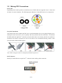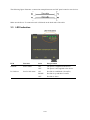
1
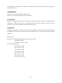
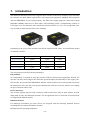
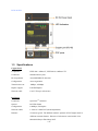
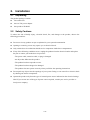
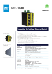
Industrial 3-Port Fast Ethernet POF
Media Converter Switches
KCD-303P-A series
KCD-303P-B series
Installation Guide
DOC.081022
1/18
(C) 2008 KTI Networks Inc. All rights reserved. No part of this documentation may be reproduced in
any form or by any means or used to make any directive work (such as translation or transformation)
without permission from KTI Networks Inc.
KTI Networks Inc. reserves the right to revise this documentation and to make changes in content from
time to time without obligation on the part of KTI Networks Inc. to provide notification of such
revision or change.
For more information, contact:
United States
KTI Networks Inc.
P.O. BOX 631008
Houston, Texas 77263-1008
Phone:
713-2663891
Fax:
713-2663893
E-mail: [email protected]
International
URL:
http://www.ktinet.com/
Fax:
886-2-26983873
E-mail: [email protected]
URL:
http://www.ktinet.com.tw/
2/18
The information contained in this document is subject to change without prior notice. Copyright (C)
All Rights Reserved.
TRADEMARKS
Ethernet is a registered trademark of Xerox Corp.
OptoLock is a registered trademark of Firecomms Ltd.
TM
FCC NOTICE
This device complies with Class B Part 15 the FCC Rules. Operation is subject to the following two
conditions: (1) This device may not cause harmful interference, and (2) this device must accept any
interference received including the interference that may cause.
CE NOTICE
Marking by the symbol
indicates compliance of this equipment to the EMC directive of the European
Community. Such marking is indicative that this equipment meets or exceeds the following technical
standards:
EMC Class B
EN 50081-1/1992 :EN55022:1994/A1:1995/A2:1997 Class B
EN61000-3-2:2000
EN61000-3-3:1995/A1:2001
EN 55024:1998/A1:2001
IEC 61000-4-2:1995
IEC 61000-4-3:1995
IEC 61000-4-4:1995
IEC 61000-4-5:1995
IEC 61000-4-6:1996
IEC 61000-4-8:1993
IEC 61000-4-11:1994
3/18
Table of Contents
1. Introduction ................................................................................................................................5
1.1
Features ..............................................................................................................6
1.2
Product Panels....................................................................................................6
1.3
Specifications ......................................................................................................7
2. Installation ..................................................................................................................................9
2.1
Unpacking ...........................................................................................................9
2.2
Safety Cautions...................................................................................................9
2.3
Mounting on a Wall ...........................................................................................10
2.4
Panel Mounting .................................................................................................11
2.5
Din-Rail Mounting..............................................................................................12
2.6
Applying Power with Power Adapter .................................................................13
2.7
Applying Power via USB ...................................................................................14
3. Making LAN Connections........................................................................................................15
3.1
Making Copper Port (RJ-45) Connections ........................................................15
3.2
Making POF Connections .................................................................................16
3.3
LED Indication...................................................................................................17
4. Applications..............................................................................................................................18
4.1
Application in Industrial Networks .....................................................................18
4.2
Application For Home Network .........................................................................18
4.3
Copper to POF Media Converter Application ....................................................18
4/18
1. Introduction
The industrial rated KCD-303P series supports three switched connections including copper and fiber
for networks over POF (Plastic Optical Fiber). The copper ports support 10/100Mbps auto-negotiation
and auto-MDI/MDIX for Cat.5 plug-and-play. The fiber ports support plug-less connections of high
bandwidth 100Mbps data rate over POF cables. POF technology offers a complementary solution to
UTP copper wire for industrial, office and home networks because it is low cost, weight little, thin,
easy and safe to install and electronic noise immunity.
Depending on the types of the network ports and the supported POF cables, several different models
are defined as follows:
Model
Copper Port (RJ-45)
Fiber Port (POF)
POF Support
KCD-303P-A1
2 ports
1 port
1.5mm
KCD-303P-A2
2 ports
1 port
2.2mm
KCD-303P-B1
1 port
2 ports
1.5mm
KCD-303P-B2
1 port
2 ports
2.2mm
The switch also provide the following advantages:
Plug and Play
No configuration is required in using the switches. With the featured auto-negotiation function, the
switches can detect and configure the connection speed and duplex automatically for the copper ports.
The switches also provide auto MDI/MDI-X function, which can detect the connected cable and switch
the transmission wire pair and receiving pair automatically. This auto-crossover function can simplify
the type of network cables used.
POF Connectivity
The switches support plug-less POF connection. Both model series offer an ideal solution for POF
deployment in home and industrial networks. For the application need, 1.5mm POF and 2.2mm POF
are supported in different models.
Industrial Features
For industrial environment, the main devices are designed with the following enhanced features
exceeding that of commercial Ethernet switches:
High and wide operating temperature
5/18
Screw panel-mounting support for industrial enclosure
Optional AC-DC power adapters with extended operating temperature range
Industrial-rated Emission and Immunity performance
1.1
Features
Supports 3 switching-base network segments – [2 x Copper, 1 x POF] and [1 x Copper, 2 x POF]
Auto MDI/MDI-X crossover function on the UTP copper port
Supports IEEE 802.3x flow control for full-duplex operation
Supports Back-pressure flow control for half-duplex operation
Wide operating temperature range for temperature critical environment
Supports desktop mounting, panel mounting, and optional Din-rail mounting
Industrial-rated Emission and Immunity performance
1.2
Product Panels
The following figure illustrates the faces of the switches:
KCD-303P-A
6/18
KCD-303P-B
1.3
Specifications
Copper Ports
Compliance
IEEE 802.3 10Base-T, IEEE 802.3u 100Base-TX
Connectors
Shielded RJ-45 jacks
Pin assignments
Auto MDI/MDI-X detection
Configuration
Auto-negotiation
Transmission rate
10Mbps, 100Mbps
Duplex support
Full/Half duplex
Network cable
Cat.5 UTP up to 100 meters
POF Ports
Connectors
OptoLockTM connector
Optical
RCLED 650nm
Configuration
100Mbps, Full duplex
Network cables
1.5mm or 2.2mm POF (model dependent)
Distance
50 meters typical. The different numeric aperture of POF might result in
different transmit distance. Distance of 100 meters tested with 0.3NA
Mitsubishi Rayon Eska Mega POF
7/18
Far End Fault Support
Enabled
Switch Functions
MAC Addresses Table
1K entries
Forwarding & filtering
Non-blocking, full wire speed
Switching technology
Store and forward
Maximum packet length 1552 bytes max.
Flow control
IEEE 802.3x pause frame base for full duplex operation
Back pressure for half duplex operation
Broadcast Storm
Protection design
DC IN Power Input
Interfaces
DC IN Jack ( -D 6.3mm / + D 2.0mm)
Operating Voltages
+4.75 ~ 12.6VDC
Power Consumption
2W max.
Mechanical
Dimension (base)
64 x 59 x 21 mm
Housing
Enclosed metal with no fan
Mounting Support
Panel mounting, Wall mounting, Desktop mounting
Environmental
Operating Temperature Main body 0oC ~ 70oC
Storage Temperature
-20oC ~ 85oC
Relative Humidity
10% ~ 90%
Electrical Approvals
FCC
Part 15 rule Class B
CE
EMC, CISPR22 Class B
Safety
IEC60950-1 / EN60950
8/18
2.
Installation
2.1
Unpacking
The product package contains:
The switch unit
One AC-DC power adapter
One product CD-ROM
2.2
Safety Cautions
To reduce the risk of bodily injury, electrical shock, fire, and damage to the product, observe the
following precautions.
Do not service any product except as explained in your system documentation.
Opening or removing covers may expose you to electrical shock.
Only a trained service technician should service components inside these compartments.
If any of the following conditions occur, unplug the product from the electrical outlet and replace
the part or contact your trained service provider:
- The power cable, extension cable, or plug is damaged.
- An object has fallen into the product.
- The product has been exposed to water.
- The product has been dropped or damaged.
- The product does not operate correctly when you follow the operating instructions.
Do not push any objects into the openings of your system. Doing so can cause fire or electric shock
by shorting out interior components.
Operate the product only from the type of external power source indicated on the electrical ratings
label. If you are not sure of the type of power source required, consult your service provider or
local power company.
9/18
2.3
Mounting on a Wall
The device can be mounted on a desktop or shelf. Make sure that there is proper heat dissipation from
and adequate ventilation around the device. Do not place heavy objects on the device.
To mount the device on a wall, one wall mounting hole is provided on the bottom of the device. Hang
the device on the wall reliably. The following figure illustrates example of a device bottom face:
10/18
2.4
Panel Mounting
The switches support panel mounting in industrial enclosure. A panel mounting bracket is required for
the mounting. Install the bracket onto the device as shown in the figure below:
After bracket installation, the final dimension is shown below:
KCD-303P-A
KCD-303P-B
11/18
2.5
Din-Rail Mounting
To mount the device on a Din-rail, the optional Din-rail mounting bracket is required. Install the
bracket onto the device.
After bracket installation, the device is ready to be mounted on a din-rail as shown below:
12/18
2.6
Applying Power with Power Adapter
The device provides a DC power jack for receiving DC power input from an external AC-DC power
adapter.
Two types of AC-DC power adapters are available for choice. One is with typical operating
temperature rating and the other is with extended operating temperature rating for critical applications
as follows:
Typical Rating:
0o ~ 40oC operating temperature
Extended Rating:
-10o ~ 60oC operating temperature
One power adapter is packed in each product package. Consult your purchasing agency for the right
part number which matching the operating rating you require.
Note: Before you begin the installation, check the AC voltage of your area. The AC-DC power
adapter should have the AC voltage matching the commercial power voltage in your area.
13/18
2.7
Applying Power via USB
The USB port on the common computers provides an output of 5V/500mA, equally 5V/2.5Watt, for
the connected USB devices. With an USB DC power cable, the USB power is applicable to the devices
and serves as a handy power, and eliminates the need for extra power adapters and occupation of
limited AC power sockets.
One optional “USB DC power cable” is available for purchasing to supply power for the switch via
USB connection.
To make the connection, the steps are:
1. Connect the USB “A” plug end of the cable to an USB High-power port for power source.
2. Connect power plug end of the cable to the device.
Notes:
1. The cable must be connected to USB High-power port for power source.
2. The power source maybe shared by other USB powered devices. Make sure it can deliver 500mA for
the cable to the KTI network device.
3. When connected to an USB hub, the result is unpredictable, since other devices connected to the hub
are sharing the limited DC power. When power is insufficient, the network device would operate
incorrectly.
14/18
3.
Making LAN Connections
3.1
Making Copper Port (RJ-45) Connections
The copper ports support the following connection types and distances:
Network Cables
10BASE-T:
2-pair UTP Cat. 3,4,5 , EIA/TIA-568B 100-ohm
100BASE-TX: 2-pair / 4-pair UTP Cat. 5, EIA/TIA-568B 100-ohm
Link distance: Up to 100 meters
Auto MDI/MDI-X Function
This function allows the port to auto-detect the twisted-pair signals and adapts itself to form a valid
MDI to MDI-X connection with the remote connected device automatically. No matter a straight
through cable or crossover cable connected, the ports can sense the receiving pair automatically and
configure self to match the rule for MDI to MDI-X connection. It simplifies the cable installation.
Auto-negotiation Function
The ports are featured with auto-negotiation function and full capability to support connection to any
Ethernet devices. The port performs a negotiation process for the speed and duplex configuration with
the connected device automatically when each time a link is being established. If the connected device
is also auto-negotiation capable, both devices will come out the best configuration after negotiation
process. If the connected device is incapable in auto-negotiation, the switch will sense the speed and
use half duplex for the connection.
15/18
3.2
Making POF Connections
POF Cable
Depending on the model specified, two different sizes of POF cables are supported. One is 1.5mm and
the other is 2.2mm in diameter. The following figure illustrates 2.2mm POF and Cat.5 as comparison.
Easy POF Installation
The design of the device enables the POF to be cut and terminated to the exact required length on site,
allowing even the most novice user to quickly and easily terminate the bare POF fiber. To terminate
the POF cable into OptoLockTM connector, the end of the cable is cut cleanly, and the two strands are
separated. One strand is inserted into each of two holes in the termination housing, which is then
pressed closed to hold the POF in place.
Note: When cutting the cable, use sharp knife and make a quick cut.
POF Connector
Identify TX and RX holes on OptoLockTM connector before making cable connection.
16/18
The following figure illustrates a connection example between two POF ports located on two devices:
Make sure the Rx-to-Tx connection rule is followed on the both ends of the cable.
3.3
LED Indication
LED
Function
State
Interpretation
POWER
Power status
ON
The power is supplied to the device.
OFF
The power is not supplied to the device.
ON
Port link is established. (No traffic)
BLINK
Port link is up and there is traffic.
OFF
Port link is down.
Px Link/Act.
Port Px link status
17/18
4.
Applications
4.1
Application in Industrial Networks
The following figure illustrates an application example in an industrial network. Four devices are
cascaded by POF cables.
4.2
Application For Home Network
The following figure illustrates an application example in home network.
4.3
Copper to POF Media Converter Application
The following figure illustrates an application of copper Cat.5 to POF media conversion.
18/18