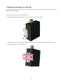
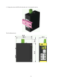
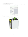
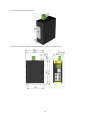
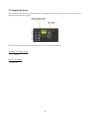
1
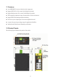
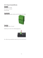
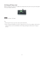
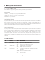
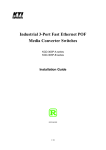
KFS-0540
Industrial 5-Port Fast Ethernet Switch
Installation Guide
DOC.091111
-1-
(C) 2009 KTI Networks Inc. All rights reserved. No part of this documentation may be reproduced in any form
or by any means or used to make any directive work (such as translation or transformation) without permission
from KTI Networks Inc.
KTI Networks Inc. reserves the right to revise this documentation and to make changes in content from time to
time without obligation on the part of KTI Networks Inc. to provide notification of such revision or change.
For more information, contact:
United States
KTI Networks Inc.
P.O. BOX 631008
Houston, Texas 77263-1008
Phone:
Fax:
E-mail:
URL:
International
713-2663891
713-2663893
[email protected]
http://www.ktinet.com/
Fax:
886-2-26983873
E-mail: [email protected]
URL:
http://www.ktinet.com.tw/
-2-
The information contained in this document is subject to change without prior notice. Copyright (C) All Rights
Reserved.
TRADEMARKS
Ethernet is a registered trademark of Xerox Corp.
FCC NOTICE
This device complies with Part 15 of the FCC Rules. Operation is subject to the following two conditions: (1)
This device may not cause harmful interference, and (2) This device must accept any interference received,
including the interference that may cause undesired operation.
CE NOTICE
Marking by the symbol indicates compliance of this equipment to the EMC directive of the European
Community. Such marking is indicative that this equipment meets or exceeds the following technical
standards:
EMC Class B
EN55022:2006
EN61000-3-2:2006
EN61000-3-3:1995/A1:2001/A2:2005 Class B
EN 55024:1998/A1:2001/A2:2003
IEC 61000-4-2:2001
IEC 61000-4-3:2002/A1:2002
IEC 61000-4-4:2004
IEC 61000-4-5:2001
IEC 61000-4-6:2003
IEC 61000-4-8:2001
IEC 61000-4-11:2001
-3-
Table of Contents
1. Introduction................................................................................................................................... 5
1.1 Features ................................................................................................................ 6
1.2 Product Panels...................................................................................................... 6
1.3 LED Indicators ...................................................................................................... 7
1.4 Specifications ........................................................................................................ 7
2. Installation..................................................................................................................................... 9
2.1 Unpacking ............................................................................................................. 9
2.2 Safety Cautions..................................................................................................... 9
2.3 Mounting the Switch to a Din-Rail ....................................................................... 10
2.4 Mounting the Switch on a Panel ......................................................................... 12
2.5 Applying Power ................................................................................................... 14
2.5.1 Using Terminal Blocks ..................................................................................... 15
2.5.2 Using DC Power Jack ...................................................................................... 16
3. Making LAN Connections.......................................................................................................... 17
3.1 10/100 Copper Ports ........................................................................................... 17
3.2 LED Indication..................................................................................................... 17
-4-
1. Introduction
The switch provides five 10/100Mbps copper ports for connections to Ethernet and Fast Ethernet devices. With
the featured auto-negotiation function, the switch can detect and configure the connection speed and duplex
automatically. The switch also provides auto MDI/MDI-X function, which can detect the connected cable and
switch the transmission wire pair and receiving pair automatically. This auto-crossover function can simplify
the type of network cables used.
For industrial environment, the device is designed with the following enhanced features exceeding that of
commercial Ethernet switches:
z
High and wide operating Temperature
z
Power input interface: Industrial screw terminal block and DC power jack for external commercial power
adapter as option
z
Screw panel and DIN rail mounting support for industrial enclosure
z
Industrial-rated Emission and Immunity performance
-5-
1.1 Features
z
Auto MDI/MDI-X crossover function on the copper port
z
Support IEEE 802.3x flow control for full-duplex operation
z
Support Back-pressure flow control for half-duplex operation
z
Wide operating temperature range for temperature critical environment
z
Support DIN-rail mounting and panel mounting
z
Provide two power input types to meet more application needs
z
Accept wide power input voltage range for application flexibility
z
Industrial-rated Emission and Immunity performance
1.2 Product Panels
The following figure illustrates the panels of the switch:
-6-
1.3 LED Indicators
LED
Function
POWER
Power status
1-5
Port 1 – Port 5
LINK
Link and activity status (Port 1 - Port 5)
100M
100Mbps speed status (Port 1 - Port 5)
1.4 Specifications
10/100 Copper Ports
Compliance
IEEE 802.3 10Base-T, IEEE 802.3u 100Base-TX
Connectors
Shielded RJ-45 jacks
Pin assignments
Auto MDI/MDI-X detection
Configuration
Auto-negotiation or software control
Transmission rate
10Mbps, 100Mbps
Duplex support
Full/Half duplex
Network cable
Cat.5 UTP up to 100 meters
Switch Functions
Forwarding & filtering
Non-blocking, full wire speed
Switching technology
Store and forward
Maximum packet length 1536 bytes
MAC Addresses Table
2K entries
Port configuration
Auto-negotiation for speed and duplex
Flow control
IEEE 802.3x pause frame base for full duplex operation
Back pressure for half duplex operation
Storm control
Broadcast packets are dropped when large consecutive broadcast packets are
received.
DC Power Input
Screwed terminal block 3P (Vin+, Vin-, Chassis Ground)
DC Jack Connector
-D 6.3mm / + D 2.0mm
Operating Voltages
+7 ~ +30VDC
Power Consumption
2.2W max.
Mechanical
Dimension (base)
40 x 80 x 95 mm (WxDxH)
Housing
Enclosed metal with no fan
-7-
Mounting
Din-rail mounting
Panel mounting (optional)
Environmental
Operating Temperature Typical -10oC ~ +70oC
Storage Temperature
-20oC ~ +85oC
Relative Humidity
10% ~ 90% non-condensing
Electrical Approvals
FCC
Part 15 rule Class B
CE
EMC, CISPR22 Class B
EN55022:2006
EN61000-3-2:2006
EN61000-3-3:1995/A1:2001/A2:2005 Class B
EN 55024:1998/A1:2001/A2:2003
IEC 61000-4-2:2001
IEC 61000-4-3:2002/A1:2002
IEC 61000-4-4:2004
IEC 61000-4-5:2001
IEC 61000-4-6:2003
IEC 61000-4-8:2001
IEC 61000-4-11:2001
Safety
LVD, IEC60950-1
-8-
2. Installation
2.1 Unpacking
The product package contains:
z The switch unit for Din-rail mounting
z One product CD-ROM
2.2 Safety Cautions
To reduce the risk of bodily injury, electrical shock, fire and damage to the product, observe the following
precautions.
z
Do not service any product except as explained in your system documentation.
z
Opening or removing covers may expose you to electrical shock.
z
Only a trained service technician should service components inside these compartments.
z
If any of the following conditions occur, unplug the product from the electrical outlet and replace the part
or contact your trained service provider:
- The power cable, extension cable, or plug is damaged.
- An object has fallen into the product.
- The product has been exposed to water.
- The product has been dropped or damaged.
- The product does not operate correctly when you follow the operating instructions.
z
Do not push any objects into the openings of your system. Doing so can cause fire or electric shock by
shorting out interior components.
z
Operate the product only from the type of external power source indicated on the electrical ratings label. If
you are not sure of the type of power source required, consult your service provider or local power
company.
-9-
2.3 Mounting the Switch to a Din-Rail
In the product package, a DIN-rail bracket is provided or has been installed for mounting the switch in a
industrial DIN-rail enclosure.
The steps to mount the switch onto a DIN rail are:
1. Install the mounting bracket onto the switch unit with screws as shown below:
2. Attach bracket to the lower edge of the DIN rail and push the unit upward a little bit until the bracket can
clamp on the upper edge of the DIN rail.
-10-
3. Clamp the unit to the DIN rail and make sure it is mounted securely.
The final dimension is:
-11-
2.4 Mounting the Switch on a Panel
The switches may be provided optionally with a panel mounting bracket. The bracket supports mounting the
switch on a plane surface securely.
The mounting steps are:
1. Install the mounting bracket on the switch unit.
-12-
2. Screw the bracket on the switch unit.
3. Screw the switch unit on a panel and the locations for screws are shown below:
-13-
2.5 Applying Power
The switch provides two types of power interfaces, terminal block and DC power jack for receiving DC power
input from external power supply.
The DC power requirements no matter which interface is used for the switch are:
Operating Vin Voltage Range
+7V ~ +30VDC
Power Consumption
2.2Watts max.
-14-
2.5.1 Using Terminal Blocks
3P Contacts
Vin Positive (+) terminal
Vin Negative (-) terminal
Chassis ground
3P Terminal Plug
A plug is provided together with the switch. The plug is shown below:
Power Wires
24 ~ 12AWG (IEC 0.5~2.5mm2)
Install the power source wires with the plug properly.
Note: When using terminal block connectors, put a cap on the DC jack.
-15-
2.5.2 Using DC Power Jack
When an external power system is not available, the switch provides a DC jack to receive power from typical
AC-DC power adapter alternatively.
Interfaces
DC Jack ( -D 6.3mm / + D 2.0mm)
Note:
1. When using DC Jack, put caps on the contacts of the terminal block.
2. Before you begin the installation, check the AC voltage of your area. The AC power adapter which is used to
supply the DC power for the unit should have the AC voltage matching the commercial power voltage in
your area
.
-16-
3. Making LAN Connections
3.1 10/100 Copper Ports
The 10/100 RJ-45 copper ports support the following connection types and distances:
Network Cables
10BASE-T:
2-pair UTP Cat. 3, 4, 5, EIA/TIA-568B 100-ohm
100BASE-TX: 2-pair UTP Cat. 5, EIA/TIA-568B 100-ohm
Link distance: Up to 100 meters
Auto MDI/MDI-X Function
This function allows the port to auto-detect the twisted-pair signals and adapts itself to form a valid MDI to
MDI-X connection with the remote connected device automatically. No matter a straight through cable or
crossover cable are connected, the ports can sense the receiving pair automatically and configure themselves to
match the rule for MDI to MDI-X connection. It simplifies the cable installation.
Auto-negotiation Function
The ports are featured with auto-negotiation function and full capability to support connection to any Ethernet
devices. The port performs a negotiation process for the speed and duplex configuration with the connected
device automatically when each time a link is being established. If the connected device is also
auto-negotiation capable, both devices will come out the best configuration after negotiation process. If the
connected device is incapable in auto-negotiation, the switch will sense the speed and use half duplex for the
connection.
3.2 LED Indication
LED
Function
State
Interpretation
Power
Power status
ON
The power is supplied to the switch.
OFF
The power is not supplied to the switch.
ON
100Mbps speed is used on the port.
OFF
10Mbps speed is used on the port.
ON
A 10Mbps or 100Mbps link is established on the port.
100M
LINK
100Mps status
Port link status
(No traffic)
BLINK Port link is up and there is traffic.
OFF
Port link is down.
-17-