1
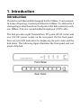
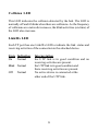
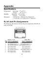
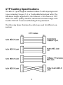
Installation Guide
10Base-T Ethernet Hub
Model: DH8T
DOC.980213-DH8T-K
P/N: 750-0104-001
KTI Networks Inc. All rights reserved. No part of this documentation may be
reproduced in any form or by any means or used to make any directive work
(such as translation or transformation) without permission from KTI Networks Inc.
KTI Networks Inc. reserves the right to revise this documentation and to
make changes in content from time to time without obligation on the part of
KTI Networks Inc. to provide notification of such revision or change.
For more information, contact:
United States
KTI Networks Inc.
P.O. BOX 631008
Houston, Texas 77263-1008
Phone: 713-2663891
Fax:
713-2663893
BBS:
713-2663015
E-mail: [email protected]
Web: http://www.ktinet.com/
International
Fax:
886-2-26983873
E-mail: [email protected]
Web: http://www.ktinet.com.tw/
The information contained in this document is subject to change without prior notice.
Copyright Ó KTI. All Rights Reserved.
TRADEMARKS
Ethernet is a registered trademark of Xerox Corp. NetWare is a registered trademark
of Novell Inc.
WARNING:
This equipment has been tested and found to comply with the limits for a Class A
digital device, pursuant to Part 15 of the FCC Rules. These limits are designed to
provide reasonable protection against harmful interference when the equipment is
operated in a commercial environment. This equipment generates, uses, and can
radiate radio frequency energy and if not installed and used in accordance with the
instruction manual may cause harmful interference in which case the user will be
required to correct the interference at his own expense.
NOTICE:
(1)The changes or modifications not expressively approved by the party
responsible for compliance could void the user’s authority to operate the
equipment.
(2)Shielded interface cables and AC power cord, if any, must be used in order to
comply with the emission limits.
CISPR A COMPLIANCE:
This device complies with EMC directive of the European Community and meets or
exceeds the following technical standard.
EN 55022 - Limits and Methods of Measurement of Radio Interference Characteristics of Information Technology Equipment. This device complies with CISPR Class
A.
WARNING: This is a Class A product. In a domestic environment this product may
cause radio interference in which case the user may be required to take adequate
measures.
CE NOTICE
Marking by the symbol CE indicates compliance of this equipment to the EMC
directive of the European Community. Such marking is indicative that this equipment meets or exceeds the following technical standards:
EN 55022: Limits and Methods of Measurement of Radio Interference characteristics of Information Technology Equipment.
EN 50082/1:Generic Immunity Standard -Part 1: Domestic Commercial and Light Industry.
EN 60555-2: Disturbances in supply systems caused by household appliances and similar
electrical equipment - Part 2: Harmonics.
10BASE-T ETHERNET HUB
INSTALLATION GUIDE
DOC.980214-DH8T-NK
P/N:750-0104-002
Table of Contents
Chapter 1 Introduction
Introduction ............................................................................... 1
Features .................................................................................... 2
Chapter 2 Installation
Installation ................................................................................. 3
Checking AC Power .................................................................. 3
Chapter 3 Making Network Connection
Network Connectors .................................................................. 4
Connecting to an Ethernet Node ............................................... 5
Hub to Hub Connection via UTP Cable ...................................... 6
Chapter 4 Interpreting Hub LEDs
Locations of the Hub LED Indicators ......................................... 8
Interpretation ............................................................................. 8
Appendix
Specifications .......................................................................... 10
RJ-45 Jack Pin Assignments .................................................. 10
UTP Cabling Specifications ...................................................... 11
1. Introduction
Introduction
This hub is an Ethernet Hub designed for the 10Base-T environment.
In terms of topology, twisted-pair Ethernet 10Base-T is defined as a
star topology rather than a bus. Each port on the hub connects to only
one 10Base-T device via unshielded twisted-pair (UTP) cable.
The hub provides eight Twisted-Pair (TP) ports (RJ-45 Jacks) and
one 12V DC power socket on the rear panel. On the front panel,
there are ten LED indicators for displaying the port status and the
hub status. The following figure illustrates the front panel and rear
panel of the hub:
1
Features
• Network ports: 8 TP ports
• Standard: TP ports conform to IEEE 802.3 10Base-T std.
• Provides an additional RJ-45 jack labeled '8C' on the TP Port #8
for connecting to another hub. A standard straight-through
10Base-T UTP cable can be used for the hub-to-hub connection.
• Each TP port has one Link/Rx LED to indicate the link and
receiving activity status of the UTP link segment.
• Each TP port can detect and correct wiring polarity reversal
automatically.
• Two LEDs are provided to indicate other activities of the hub:
Power LED
Collision LED
Power status
Network collision status
2
2. Installation
Installation
You can place the hub in an area that meets the following specifications:
o
o
Temperature: 5 to 40 C when operating
Humidity: 10% to 80% when operating
Dimension: 195 mm x 129 mm x 28 mm (WxDxH)
Checking AC Power
One AC power adapter is contained in the hub package. Before you
begin the installation, check the AC voltage of your area. The AC
power adapter which is used to supply the DC power for the hub
should have the AC voltage matching the commercial power voltage
at your area.
The specifications of the AC power adapter are:
AC input power: AC power voltage of your area
DC output power: 12 VDC 500mA min.
DC plug type:
3
3. Making Network Connections
Network Connectors
The hub has 8 TP ports which are presented by 8 RJ-45 jacks. The
jacks labeled 1 through 8 are permanently configured as 10Base-T
MDI-X jacks and the jack labeled '8C' next the jack labeled '8' is an
alternative jack which is configured as MDI jack for the TP port #8.
Both jacks can not be used at the same time.
The MDI-X jacks can support connections to 10Base-T Ethernet
nodes or lower level hubs via 10Base-T UTP cables. The MDI jack
'8C' is used for connecting to an upper level hub.
A 10Base-T UTP cable can be a Category 3, 4, or 5 unshielded
twisted-pair cable with an RJ45 plug at each end.
4
Connecting to an Ethernet Node
To connect the hub to a 10Base-T Ethernet node, follow these steps:
1. Select an appropriate length of 10Base-T UTP cable for the
connection.
2. Connect one end of the UTP cable to the MDI jack on the
remote device (e.g., a PC equipped with 10Base-T Ethernet
adapter).
3. Connect the other end of the UTP cable to an available MDI-X
jack on the hub. It is better to reserve jack #8 for a connection to
another hub.
Make sure that the connector on the cable is wired appropriately for
the standard 10Base-T node. The 'straight through' connection should
be made from the node through the cable and connectors to the hub.
Refer to Appendix 'RJ-45 Jack Pin Assignments' for the information
of UTP wire pairs.
Hub to Hub Connection via UTP Cable
5
When the number of 10Base-T nodes in your network exceeds eight,
you need to connect at least two hubs to integrate all 10Base-T nodes
into one network. You may connect one hub to another hub by using
an ordinary UTP cable as the following steps:
1. Connect one end of the UTP cable to the jack labeled '8C' of
Hub A.
2. Connect the other end of the cable to any available MDI-X jack
of Hub B.
The maximum length of the UTP cable connecting two hubs is 100
meters.
6
When connecting more than two hubs via TP ports and UTP cables,
it is important to minimize the number of hubs in any path of the
network.
You may select one hub to serve as a primary hub to which other
hubs will be connected. This will minimize the number of hubs in any
path (node to node) on the network. The following figure illustrates
an example of connection topology:
7
4. Interpreting Hub LEDs
Locations of the Hub LED Indicators
The hub provides the following LEDs :
• One Power status LED
• One Collision status LED
• Eight Link and activity status LEDs. One for each TP port
Interpretations
Power LED
The LED indicates the status of the hub's power source. Match the
activity of the LED with one of the states indicated in the table.
State Indication
On
Normal
Off Problem
Interpretation
The power of the hub is on.
No power is being supplied to the hub.
8
Collision LED
This LED indicates the collision detected by the hub. The LED is
normally off and it blinks when there are collisions. As the frequency
of collisions on a network increases, the blink activities (on-time) of
the LED also increase.
Link/Rx LED
Each TP port has one Link/Rx LED to indicate the link status and
receiving activities of the connection to the attached device.
State Indication
On
Normal
Blink Normal
Off
Normal
Interpretation
the UTP link is in good condition and no
receiving activities are present.
the UTP link is in good condition and
there receiving activities are present.
No active device is connected at the
other end of the UTP link.
9
Appendix
Specifications
Temperature:
Humidity:
Dimension:
o
o
Operating 5 to 40 C
o
o
Storage
-40 to 70 C
Operating 10% to 80%
Storage
5% to 90%
195mm (W) x 129mm (D) x 28mm (H)
7.7 inch (W) x 5.1 inch (D) x 1.1 inch (H)
RJ-45 Jack Pin Assignments
The following illustrations indicate the pin assignments of the RJ-45
jacks on the hub.
Jacks '1'-'8'
Pin Jack Assignment
1
2
3
4
5
6
7
8
Jack '8C'
Jack Assignment
INCOMING DATA 1(+) OUTGOING DATA1(+)
INCOMING DATA 1(-) OUTGOING DATA 1(-)
OUTGOING DATA 1(+) INCOMING DATA 1(+)
(No Connection)
(No Connection)
(No Connection)
(No Connection)
OUTGOING DATA 1(-) INCOMING DATA 1(-)
(No Connection)
(No Connection)
(No Connection)
(No Connection)
10
UTP Cabling Specifications
The hub's TP ports support standard 10Base-T cable topologies and
types, including Category 3, 4, or 5 unshielded twisted pair cable. The
maximum length supported by the Ethernet is 100 meters of UTP
cable. The cable, quality, distance, and connectors must comply with
the EIA/TIA 568 'Commercial Building Wiring Standard'.
The following figure illustrates the cable types used for different connections:
11