1
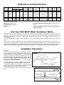
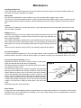
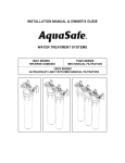
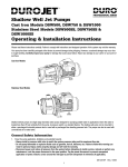
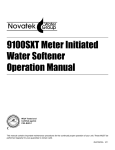
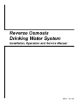
5600
Meter Initiated Valve
Water Softener
Operation Manual
Read all instructions carefully before operation.
#51401
05/05
Performance and Specifications
Item
Number
Model
Number
Capacity at regeneration salt levels
(kilograins as CaCO3)
Twin Tank Models
7600
5600MI-20
7601
5600MI-30
7602
5600MI-45
7603
5600MI-60
7604
5600MI-90
Cabinet Models
7378
WTC5620
7379
WTC5630
Service Flow
Rate
Maximum
Flow To Drain
Mineral Tank
Size
Brine Tank
Size
Resin
Volume
Salt
Capacity
Shipping
Weight
@15lb/cf
@10lb/cf*
@6lb/cf
USGPM (LPM)
USGPM (LPM)
inches (mm)
inches (mm)
cu.ft. (litres)
Lbs. (kg)
Lbs. (kg)
22
30
45
60
90
20
27
41
55
82
15
20
30
40
60
8.0 (30.3)
10.0 (37.9)
11.0 (41.6)
15.0 (56.8)
15.0 (56.8)
1.2 (4.5)
1.5 (5.7)
2.0 (7.6)
3.0 (11.4)
4.0 (15.1)
8 x 47 (203 x 1194)
9 x 48 (229 x 1219)
10 x 54 (254 x 1372)
12 x 52 (305 x 1321)
14 x 65 (356 x 1651)
18 x 35 (457 x 889)
18 x 35 (457 x 889)
21 x 36 (533 x 914)
21 x 36 (533 x 914)
21 x 36 (533 x 914)
0.75 (21.2)
1.00 (28.3)
1.50 (42.5)
2.00 (56.6)
3.0 (84.5)
224 (101.6)
224 (101.6)
308 (139.7)
308 (139.7)
308 (139.7)
90 (40.8)
105 (47.6)
140 (63.5)
185 (83.9)
255 (115.7)
20
30
18
27
13
20
6 (22.7)
10 (37.9)
1.2 (4.5)
2.0 (7.6)
8 x 35 (203 x 889)
10 x 35 (254 x 889)
21x13x44 (533x330x1118)
21x13x44 (533x330x1118)
0.67 (19)
1.00 (28)
359 (163)
359 (163)
73 (33)
90 (41)
Caution: These water conditioners are not intended to be used for treating water that is microbiologically unsafe or of unknown quality without adequate
disinfection before or after the system.
Notes:
Operating Temperature Range: 110°F (43°C)
Operating Pressure Range: 100 psig (689 kPa)
Electrical: Standard 110V
Pipe size: 3/4””
1. “*” designates that 10 lb/cf is the factory salt setting for all units.
2. Capacities of softeners may deviate from the chart above depending on flow rates and raw water
conditions.
3. The manufacturer reserves the right to make product improvements which may deviate from the
specifications and descriptions stated herein without obligation to change previously manufactured
products or to note the change.
4. 1 Kilograin is equal to 1000 grains.
How Your 5600 MI-DF Water Conditioner Works
Hard water enters your home through the main supply line, enters your water conditioner, and passes down through a bed of ion
exchange resin which softens and filters the water as well. An ion exchange process takes place in which the resin beads capture and
hold calcium and magnesium, the hardness impurities, while the water takes on sodium ions. The soft water then flows up and into your
household water line.
Your meter initiated water conditioner is set by aligning the number of people with the grains of hardness on the program wheel. See
page 4.
On the days your conditioner regenerates, the resin is automatically recharged by passing a brine solution (salt water) through it. This
reverses the ion exchange process, charging the resin with sodium and freeing the hardness minerals. These minerals and the brine
solution are then flushed away through the drain line followed by a rapid rinse. The resin bed is again ready to soften water. The proper
volume of water is returned to the brine tank to dissolve enough salt for the next regeneration. All this is performed automatically.
Installation Instructions
CAUTION:
If the ground from the electrical panel or breaker box to the water
meter or underground copper pipe is tied to the copper water lines
and these lines are cut during installation of the Noryl bypass
valve and/or poly pipe, an approved grounding strap must be
used between the two lines that have been cut in order to maintain
continuity. The length of the grounding strap will depend upon the
number of units being installed and/or the amount of copper pipe
being replaced with poly. See Figure 1.
Figure 1
Electrical Panel
Ground Strap
Copper Pipe
Ground
From
Panel
In all cases where metal pipe was originally used and is later
interrupted by poly pipe or the Noryl bypass valve as in Figure 1
or by physical separation as in Figure 2, to maintain proper
metallic pipe bonding, an approved ground clamp c/w not less
than #6 copper conductor must be used for continuity.
Poly Pipe
Poly Pipe
Water Meter
Softener
c/w Plastic Bypass
Check your local electrical code for the correct clamp and cable
size.
Figure 2
Outside Water Line For Outside & 3rd Tap Comes From Meter
Unfiltered Water Bypass
Loop Cut & Capped
Filtered Water Line in Home
1
Ground Strap Required
Because of Break in Continuity
Installation Instructions
1. Determine the best location for your water softener,
bearing in mind the location of your water supply lines,
drain line and 110 volt AC electrical outlet. Subjecting the
softener to freezing or temperatures above 110°F (43°C)
will void the warranty.
2. Water to supply outside faucets used to water lawns and
gardens should not be softened. A new water line is often
required to be connected to supply hard water to the inlet
of the water softener and to the outside faucets. Cut the
water line between where it enters the house; before any
BRINE
lines that branch off to feed the hot water heater or other
LINE
fixtures in the house; and as near the desired location of
the water softener as possible. Install a tee fitting on the
DRAIN
feed end of the cut pipe and an elbow fitting on the other
LINE
OUTLET
end. Install piping from the tee to the inlet of the water
INLET
softener and from the elbow to the outlet to the softener.
To server the water lines which branch off to feed outside
faucets, cut the branch lines approximately two inches
Rear View - Plumbing Hook-Up
from the fitting on the main water line. Install an elbow on
the end of the pipe nearest the outside faucet and a cap
on the end connected to the existing water line. Install piping from the tee on the inlet to the water softener to the elbow
on the pipe to the outside faucet. Following this procedure will result in all lines in the house, with the exception of the
outside faucets but including the water heater and therefore the hot water lines, being supplied with soft water.
3. Familiarize yourself with the location of the inlet, outlet and drain on the control valve. Be very careful not to get the
controls wet.
4. Attach the bypass valve to the control valve. Connect the inlet and outlet of the water softener to the plumbing in the
house. The control valve must not be subjected to temperatures above 71°C (160°F). To avoid damaging the control
valve when sweat fittings are used, solder the threaded copper adapters to the copper pipe and then, using teflon tape,
screw the assembly into the bypass valve.
CAUTION - do not use pipe thread compound as it may attack the material in the valve body.
5. Using teflon tape, screw the 1/2” hose barb into the drain port in the valve. Attach 1/2” drain hose to the hose barb and
tighten securely with a hose clamp. Run the drain line to a floor drain or a laundry drain. Complete any necessary
plumbing.
6. On the twin tank units, pull the 3/8” brine line through the hole in the side of the brine tank. Connect the brine line to
the fitting on the side of the valve using the nut and ferrule. Tighten snugly.
2
7. Make sure the bypass valve is in the service position.
8. Set the time of day and the program wheel according to the instructions on page 4.
9. Remove back cover plate. Make sure that the salt dosage is set as recommended on page 5.
NOTE: The various regeneration positions may be dialed manually by turning the large knob on the front of the control
clockwise, until the indicator shows the desired position.
10. Turn the large knob to the backwash position. Turn on the water supply to the valve and wait until water starts running
at the drain. Allow the water to run at the drain for 2 to 3 minutes.
11. Turn the knob advancing the valve to the brine and rinse position. Allow the water to run at the drain for a further 2 to
3 minutes. Using the same procedure, turn the knob to rapid rinse position and allow to run for a few minutes.
12. Plug the conditioner in. Manually turn the knob to the start of the brine refill position. The correct amount of water will
be automatically metered through the air check tube in the brine well into the brine tank, and the control will
automatically return to the service position. The service position is indicated by the word SERVICE on the front dial.
13. Replace back cover on the control module.
14. Put a minimum of 40 kg of crystal water softener salt in the brine tank. The unit will automatically fill to the correct level
when it regenerates.
ALL STATE AND LOCAL GOVERNMENT CODES GOVERNING INSTALLATION OF THESE DEVICES MUST BE OBSERVED.
Optional Sanitization Procedure: We recommend that all new water conditioners be disinfected as part of the startup.
Sanitization is achieved by the application of chlorine in the regeneration cycle of the conditioner. A liquid solution of
5.25% sodium hypochlorite (commonly referred to as household bleach) is recommended as a suitable disinfectant. Use
only unscented products. For every cubic foot of resin in the softener, pour approximately two (2) tablespoons of sodium
hypochlorite into the brine well tube. The brine tank refill in Step 12 should add the correct amount of water to the brine
tank. If not, the water can be added manually now. Press and hold the EXTRA CYCLE button to begin a manual
regeneration. Press the EXTRA CYCLE button again to advance the valve to the Brine/Rinse position. Allow softener to
complete the Brine/Rinse cycle, then let the manual regeneration continue until the brine tank is refilled again with the
correct amount of water.
3
Operating Instructions
Setting the Time of Day (Figure 3)
This is a 24-hour timer and must correspond with the correct time on your wrist watch
to ensure proper cycling of your conditioner. Disengage the drive gear by pressing and
holding in the RED BUTTON on the left side of the control. Now turn the large 24-hour
gear until the actual time of day is at the time of day arrow at the bottom of the panel.
Release the red button to re-engage the drive gear. The correct time of day on the 24hour clock has now been set.
Time of Regeneration
The time of regeneration is factory set at 2:00 a.m.
Figure 3
Manual Regeneration Cycle (Figure 4)
Should you run out of soft water due to inadequate frequency of regeneration or
inadequate reserve capacity, power failure, lack of salt, or excessive usage because
of unexpected company, you can initiate a manual regeneration simply by turning the
manual regeneration knob on the front of the control to “REGEN” position. The
conditioner will now automatically complete a regeneration cycle and return to service.
Be sure there is adequate salt and salt brine in the brine tank for a satisfactory
regeneration.
Setting the Regeneration Frequency
Figure 4
There are only two methods for setting the program wheel, use only one of the
following methods.
Setting the Program Wheel – Method 1 (See Figure 5)
Set the program wheel by lifting the “people” dial and rotating it so the number of
people in the household is aligned with the grains per gallon water hardness scale.
Release the dial and check for firm engagement at setting. (This method will provide
reserve capacity based on 75 gallons per person per day.)
Setting the Program Wheel – Method 2
The frequency of automatic regeneration can alternatively be set by using the gallon
label and the small white dot on the program wheel. Set the program wheel by lifting
the “people” dial and while pulling it towards you, turn it until the desired number of
gallons is aligned with the white dot on the circumference. The number of gallons is
read by multiplying the number on the label by 100. To determine the number of
gallons of softened water that can be produced between regenerations, use the
following formula.
Figure 5
Frequency of Automatic Regeneration
Meter Initiated Models Only
Step 1
Capacity between regenerations (see Specifications on page 1). Example: Model 5600MI30 = 27,000 grains @ 10 lbs of salt. Assume
25 grains/gal, divided by grains of hardness in water sample which equates to the number of gallons between regenerations.
Example: 27,000 ÷ 25 = 1,080 gal.
Step 2
The advantage to setting the program wheel by method 2 is that you decide how much reserve capacity you want your unit to have.
Method 1 assumes water usage of 75 gallons per day. However, if you want more or less reserve, simply assume more or less water
usage per person a day. The next step in the example assumes that the water usage will be less and therefore, the unit will not need
the extra reserve capacity.
Number of gallons between regeneration
–
Reserve capacity (Number of people x 75 gallons)
=
Number of gallons at which to set the program wheel
NOTE: Add one person if you have a dishwasher.
4
Salt Settings are factory set and should not need adjustment
5600MI-20 ................................8 lbs
WTC5620 .................................7 lbs
5600MI-30 ..............................10 lbs
WTC5630 ...............................10 lbs
5600MI-45 ..............................15 lbs
5600MI-60 ..............................10 lbs
5600MI-90 ..............................15 lbs
Automatic Bypass
The regeneration cycle lasts approximately 2-1/2 hours, after which soft water service will be restored. During regeneration, hard water
is automatically bypassed for use in the household. Hot water should be used as little as possible during this time to prevent hard water
from filling the water heater. This is why automatic regeneration is set for sometime during the night and manual regenerations should
be performed when little or no water will be used in the household.
Safety Float
The brine tank is equipped with a safety float which prevents your brine tank from overfilling as a result of a malfunction such as a power
failure.
Water Pressure
Your softener is designed to operate under normal water pressures from 20 psi (1.4 atm) to 120 psi (8.2 atm).
New Sounds
You may notice new sounds as your water softener operates. The regeneration cycle lasts approximately 2-1/2 hours. During this time,
you may hear water running intermittently to the drain.
Manual Bypass (Figure 6)
In the case of emergency, such as an overflowing brine tank, you can isolate your
water softener from the water supply using the bypass valve located at the back of the
control.
In normal operation the bypass is open with the on/off knobs in line with the inlet and
outlet pipes. To isolate the softener, simply rotate the knobs clockwise (as indicated
by the word BYPASS and arrow) until they lock.
Figure 6
OUTLET
You can use your water related fixtures and appliances as the water supply is
bypassing the softener. However, the water you use will be hard.
To resume soft water service, open bypass valve by rotating the knobs counterclockwise.
5
INLET
Maintenance
Checking the Salt Level
Check the salt level monthly. Remove the lid from the cabinet or brine tank, make sure salt level is always above the
brine level (you should not be able to see water).
Adding Salt
Use only clean salt labeled for water conditioner use, such as crystal, pellet, nugget, button or solar.
The use of rock salt is discouraged because it contains insoluble silt and sand which build up in the brine tank and can
cause problems with the system’s operation. Add the salt directly to the tank, filling no higher than the top of the brine
well.
Caution
Liquid brine will irritate eyes, skin and open wounds - gently wash exposed area with fresh water. Keep children away
from your water conditioner.
Figure 7
Bridging (Figure 7)
Bridging
Humidity or wrong type of salt may create a cavity between the water and the salt. This
action, known as “bridging”, prevents the brine solution from being made, leading to your
water supply being hard.
If you suspect salt bridging, carefully pound on the outside of the brine tank or pour some
warm water over the salt to break up the bridge. This should always be followed up by
allowing the unit to use up any remaining salt and then thoroughly cleaning out the brine
tank.
Allow four hours to produce a brine solution, then manually regenerate the softener.
Care of Your Softener
To retain the attractive appearance of your new water softener, clean occasionally with mild soap solution. Do not use
abrasive cleaners, ammonia or solvents. Never subject your softener to freezing or to temperatures above 110°F (43°C).
Cleaning the Injector Assembly (Figure 8)
Sediment, salt and silt will restrict or clog the injector. A clean water
supply and pure salt will prevent this from happening.
Figure 8
The injector assembly is located on the right side of the control valve.
This assembly is easy to clean.
Shut off the water supply to your softener and reduce the pressure by
opening a cold soft water faucet. Using a screwdriver, remove the two
screws holding the injector cover to the control valve body. Carefully
remove the assembly and disassemble as shown in Figure 8. The
injector orifice is removed from the valve body by carefully turning it
out with a large screwdriver. Remove the injector throat the same way.
Carefully flush all parts including the screen. Use a mild acid such as
vinegar or Pro-Rust Out to clean the small holes in the orifice and
throat.
INJECTOR BODY
INJECTOR THROAT
INJECTOR NOZZLE
“O” RING
INJECTOR COVER
INJECTOR SCREEN
SCREW
Reassemble using the reverse procedure.
Resin Cleaner
An approved resin cleaner must be used on a regular basis if your water supply contains iron. The amount of resin cleaner
and frequency of use is determined by the quantity of iron in your water (consult your local representative or follow the
directions on the resin package).
6
Trouble Shooting Guide
Before calling for service, follow the steps below, then MANUALLY REGENERATE your softener.
PROBLEM
CAUSE
1. Softener delivers hard water A.
B.
CORRECTION
Bypass valve is open
No salt in brine tank
A.
B.
F.
Plugged injector assembly
Close bypass valve.
Add salt to brine tank and maintain salt level
above water level.
C. Check salt setting and clean brine line flow
control if plugged.
D. Break salt bridging – see page 6.
E. Tighten connections at control valve and at
brine valve.
F. Clean/replace injectors and screen.
A.
Control will not draw brine properly
A.
C. Insufficient water flowing into brine tank
D. Salt bridged
E. Loose brine line
2. Intermittent soft water
B.
Using hot water during regeneration
cycle
C. Incorrect salt setting
D. Softener capacity too small
Maintain water pressure at 20 psi minimum.
Check for restrictions in drain line. Clean or
replace injector assembly. Check for air leaks
between control valve and air check valve
and tighten connections.
B. Avoid using hot water at this time as water
heater will fill with hard water.
C. Adjust salt setting.
D. Increase capacity by replacing with larger
unit.
3. Softener regenerates at
wrong time
A.
Power failure or incorrect setting
A.
Restore power and reset time of day.
4. Unit uses too much salt
A.
B.
Improper salt setting
Excessive water in brine tank
A.
B.
Check salt usage and salt setting.
Remove water. Clean drain line flow control,
brine line flow control, injector system and
brine valve.
5. Loss of water pressure
A.
A.
B.
Inlet to control blocked with iron
buildup or foreign matter
Iron buildup in water conditioner
Clean line to water softener. Remove piston
and clean control.
Clean control and add resin cleaner to resin
bed.
6. Iron in conditioned water
A.
Fouled resin bed
A.
7. Softener fails to draw brine
A. Drain line flow control is plugged
B. Brine line flow control is plugged
C. Injector assembly is plugged
D. Line pressure is too low
8. Drain flows continuously
E.
Internal control leak
A.
Foreign material in control
A. No salt in brine tank
B. Injector assembly plugged
C. Salt bridged
D. Insufficient salt used per regeneration
E. Softener capacity too small
10. Softener regenerates every A.
night
Check backwash, brine draw and brine tank
fill. Clean control and add resin cleaner to
resin bed.
A. Clean drain line flow control.
B. Clean drain line flow control.
C. Clean/replace injectors and screen.
D. Increase line pressure. Line pressure must
be at least 20 psi (139.9 KPa) at all times.
E. Change seals and spacers and/or piston
assembly.
A.
B. Internal control leak
C. Control valve is jammed in brine or
backwash position
D. Drive motor stopped or jammed
9. Softener fails to regenerate
B.
Softener capacity too small
7
Remove piston assembly and inspect bore,
remove foreign material and check control in
various regeneration positions.
B. Replace seals and/or piston assembly.
C. Replace piston and seals and spacers.
D.
Replace drive motor.
A. Add salt.
B. Clean/replace injectors and screen.
C. Break salt bridging – see page 5.
D. Check and adjust salt setting.
E. Replace softener with larger unit.
A.
Replace with larger unit.
GUARANTEE
HYDROTECH guarantees that your new water conditioner is built of quality material and workmanship. When properly
installed and maintained, it will give years of trouble-free service.
FIVE YEAR COMPLETE PARTS GUARANTEE
HYDROTECH will replace any part which fails within 60 months from date of manufacture, provided the failure is due to a
defect in material or workmanship. The only exception shall be when proof of purchase or installation is provided and then
the warranty period shall be from the date thereof.
TEN YEAR GUARANTEE ON MINERAL AND BRINE TANKS
HYDROTECH will provide a replacement mineral or brine tank to any original equipment purchaser in possession of a tank
that fails within 120 months, provided that the water conditioner is at all times operated in accordance with specifications and
not subject to freezing or exposure to direct sunlight.
GENERAL PROVISIONS
HYDROTECH assumes no responsibility for consequential damage as a result of escaped water from the water filter; labor
or expense incurred as a result of a defect or for failure to meet the terms of these guarantees because of circumstances
beyond its control.
WaterGroup Inc.
WaterGroup Companies Inc.
Fridley, Minnesota
Regina, Saskatchewan
Sun Valley, California
Cambridge, Ontario
1-800-354-7867
1-877-299-5999
www.hydrotechwater.com
Printed in Canada