1
advanced
configuration and
management guide
hp procurve routing switches
9304m, 9308m, and 6308m-sx
and the hp procurve switch
6208m-sx
(software release
6.6.x and 7.1.x)
www.hp.com/go/hpprocurve
Book 2:
Advanced Configuration and
Management Guide
for the HP ProCurve Routing Switches
9304M, 9308M, 6308M-SX
and the HP ProCurve Switch 6208M-SX
(Software Releases 6.6.X and 7.1.X)
Copyright 2000
Hewlett-Packard Company
All rights reserved. Reproduction, adaptation or
translation without prior written permission is
prohibited, except as allowed under the copyright
laws.
Safety Considerations
Prior to the installation and use of this product,
review all safety markings and instructions.
Instruction Manual Symbol.
Publication number
5969-2363
December 2000
Applicable Products
HP J4138A, HP J4139A, HP J4840A, HP J4841A
Trademark Credits
Microsoft®, Windows®, Microsoft Windows NT® and
Internet Explorer® are U.S. trademarks of Microsoft
Corporation. Netscape® Navigator is a U.S.
trademark of Netscape Communications
Corporation. Cisco® is a trademark of Cisco
Systems Inc.
Disclaimer
The information contained in this document is
subject to change without notice.
HEWLETT-PACKARD COMPANY MAKES NO
WARRANTY OF ANY KIND WITH REGARD TO
THIS MATERIAL, INCLUDING BUT NOT LIMITED
TO, THE IMPLIED WARRANTIES OF
MERCHANTABILITY AND FITNESS FOR A
PARTICULAR PURPOSE.
Hewlett-Packard shall not be liable for errors
contained herein or for incidental or consequential
damages in connection with the furnishing,
performance or use of this material.
Hewlett-Packard assumes no responsibility for the
use or reliability of its software on equipment that is
not furnished by Hewlett-Packard.
A copy of the specific warranty terms applicable to
your HP product and replacement parts can be
obtained from your HP Sales and Service Office or
authorized dealer.
Warranty
See the Customer Support and Warranty booklet
included with the product.
A copy of the specific warranty terms applicable to
your Hewlett-Packard products and replacement
parts can be obtained from your HP Sales and
Service Office or authorized dealer.
ii
If the product is marked with the above symbol, refer
to the product manual to protect the product from
damage.
WARNING Denotes a hazard that can cause injury.
CAUTION Denotes a hazard that can damage
equipment or data.
Do not proceed beyond a WARNING or CAUTION
notice until you have understood the hazard and
have taken appropriate precautions.
Use of control, adjustments or performance
procedures other than those specified herein may
result in hazardous radiation exposure.
Grounding
This product provides a protective earthing terminal.
There must be an uninterrupted safety earth ground
from the main power source to the product’s input
wiring terminals, power cord or supplied power cord
set. Whenever it is likely that the protection has
been impaired, disconnect the power cord until the
ground has been restored.
If your LAN covers an area served by more than one
power distribution system, be sure their safety
grounds are securely interconnected.
LAN cables may occasionally be subject to
hazardous transient voltages (such as lightning or
disturbances in the electrical utilities power grid).
Handle exposed metal components of the network
with caution.
For more safety information, see “Safety and EMS
Regulatory Statements” in the Installation and
Getting Started Guide.
Servicing
There are no user-serviceable parts inside the user
installable modules comprising the product. Any
servicing, adjustment, maintenance or repair must
be performed only by service-trained personnel.
Organization of Product Documentation
Read Me First
The “Read Me First” document includes software release information, a brief “Getting Started” section, an
accessory parts list, troubleshooting tips, operating notes, and other information that is not included elsewhere in
the product documentation.
NOTE: HP periodically updates Read Me First. The latest version is available at
http://www.hp.com/go/hpprocurve. (Click on Technical Support, then Manuals.)
Main Product Coverage
The main product documentation for your switch or routing switch includes:
•
Book 1: Installation and Getting Started Guide. Book 1 contains the product Safety and EMC Regulatory
statements as well as installation, security, and basic configuration information. A printed copy of this guide is
included with your HP product. An electronic copy is also included as a PDF (Portable Document Format) file
on the CD shipped with your HP product.
•
Book 2: Advanced Configuration and Management Guide. Book 2 (this manual) contains advanced
configuration information for routing protocols, Spanning Tree Protocol (STP), Quality of Service (QoS), and
Virtual LANs (VLANs). In addition, appendixes in this guide contain reference information for network
monitoring, policies and filters, and software and hardware specifications. This manual is included in a PDF
(Portable Document Format) file on the CD shipped with your HP product.
•
Book 3: Command Line Interface Reference. Book 3 provides a dictionary of CLI commands and syntax. An
electronic copy of this reference is included as a PDF (Portable Document Format) file on the CD shipped
with your HP product.
These documents also are available in PDF file format on HP's ProCurve website.
NOTE: In Book 2, most of the chapters apply only to the HP 9304M, HP 9308M, and HP 6308M-SX routing
switches (and not the HP 6208M-SX switch). However, the QoS, ACL, STP, and VLAN chapters, and appendixes
A and B apply to the HP 6208M-SX switch as well as the routing switches.
Product CD: A Tool for Finding Specific Information and/or Printing Selected Pages
This CD is shipped with your HP product and provides the following:
•
A README.txt file (or README.pdf file) describing the CD contents and use, including easy instructions on
how to search the book files for specific information
•
A contents.pdf file to give you easy access to Book 1, Book 2, and the CLI Reference on the CD
•
Separate PDF files of the individual chapters and appendixes in Book 1 and Book 2, enabling you to easily
print individual chapters, appendixes, and selected pages
•
Single PDF files for each of the books, enabling you to use the Adobe® Acrobat® Reader to easily search for
detailed information
•
An Adobe Acrobat Reader (in case you don't already have a reader installed on your PC)
•
Additional files. These may include such items as a copy of the device software (OS), additional Readme
files, and updates to network management software (HP TopTools for Hubs & Switches).
Supplements and Release Notes
These documents describe features that became available between revisions of the main product documentation.
Depending on when new features are released, you may or may not receive any supplements or release notes
with your HP product. New releases of such documents will be available on HP's ProCurve website. To register
to receive email notice from HP when a new software release is available, go to
http://www.hp.com/go/hpprocurve and click on Technical Support, then Software.
iii
iv
Contents
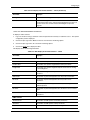
GETTING STARTED...................................................................................... 1-1
INTRODUCTION ...........................................................................................................................................1-1
AUDIENCE ..................................................................................................................................................1-1
NOMENCLATURE .........................................................................................................................................1-1
TERMINOLOGY ............................................................................................................................................1-2
RELATED PUBLICATIONS .............................................................................................................................1-2
WHAT’S NEW IN THIS EDITION? ...................................................................................................................1-3
ENHANCEMENTS ADDED IN SOFTWARE RELEASE 06.6.X .......................................................................1-3
ENHANCEMENTS ADDED IN SOFTWARE RELEASE 07.1.X .......................................................................1-3
SUPPORT AND WARRANTY INFORMATION .....................................................................................................1-5
QUALITY OF SERVICE (QOS)....................................................................... 2-1
THE QUEUES ..............................................................................................................................................2-1
AUTOMATIC QUEUE MAPPING FOR IP TYPE OF SERVICE (TOS) VALUES ...............................................2-2
QUEUING METHODS ....................................................................................................................................2-3
SELECTING THE QUEUING METHOD .......................................................................................................2-3
CONFIGURING THE QUEUES ..................................................................................................................2-4
DISPLAYING THE QOS PROFILE CONFIGURATION .......................................................................................2-10
ASSIGNING QOS PRIORITIES TO TRAFFIC ..................................................................................................2-11
CHANGING A PORT’S PRIORITY ...........................................................................................................2-11
CHANGING A LAYER 2 PORT-BASED VLAN’S PRIORITY .......................................................................2-12
REASSIGNING 802.1P PRIORITIES TO DIFFERENT QUEUES ...................................................................2-14
ASSIGNING STATIC MAC ENTRIES TO PRIORITY QUEUES ....................................................................2-16
ASSIGNING IP AND LAYER 4 SESSIONS TO PRIORITY QUEUES .............................................................2-17
ASSIGNING APPLETALK SOCKETS TO PRIORITY QUEUES .....................................................................2-25
CONFIGURING A UTILIZATION LIST FOR AN UPLINK PORT ............................................................................2-26
DISPLAYING UTILIZATION PERCENTAGES FOR AN UPLINK ...........................................................................2-28
USING ACCESS CONTROL LISTS (ACLS)..................................................... 3-1
OVERVIEW ..................................................................................................................................................3-1
v
Advanced Configuration and Management Guide
USAGE GUIDELINES FOR ACCESS CONTROL LISTS (ACLS) ..........................................................................3-2
ACL SUPPORT ON THE HP PRODUCTS .................................................................................................3-2
ACL IDS AND ENTRIES .........................................................................................................................3-2
DEFAULT ACL ACTION .........................................................................................................................3-3
CONTROLLING MANAGEMENT ACCESS TO THE DEVICE ..........................................................................3-3
ACL LOGGING .....................................................................................................................................3-3
DISABLING OR RE-ENABLING ACCESS CONTROL LISTS (ACLS) ....................................................................3-4
ENABLING ACL MODE ..........................................................................................................................3-4
DISABLING ACL MODE .........................................................................................................................3-5
CONFIGURING STANDARD ACLS .................................................................................................................3-5
STANDARD ACL SYNTAX ......................................................................................................................3-6
CONFIGURING EXTENDED ACLS ..................................................................................................................3-9
FILTERING ON IP PRECEDENCE AND TOS VALUES ..............................................................................3-10
EXTENDED ACL SYNTAX ....................................................................................................................3-11
CONFIGURING NAMED ACLS .....................................................................................................................3-18
MODIFYING ACLS .....................................................................................................................................3-19
APPLYING AN ACL TO A SUBSET OF PORTS ON A VIRTUAL INTERFACE .......................................................3-21
ENABLING STRICT TCP OR UDP MODE ....................................................................................................3-21
ENABLING STRICT TCP MODE ............................................................................................................3-22
ENABLING STRICT UDP MODE ...........................................................................................................3-22
DISPLAYING ACLS ....................................................................................................................................3-23
DISPLAYING THE LOG ENTRIES ..................................................................................................................3-23
POLICY-BASED ROUTING (PBR) ................................................................................................................3-24
CONFIGURING PBR ............................................................................................................................3-25
ENABLING PBR ..................................................................................................................................3-27
CONFIGURATION EXAMPLES ...............................................................................................................3-27
RATE LIMITING............................................................................................ 4-1
FIXED RATE LIMITING ..................................................................................................................................4-1
HOW FIXED RATE LIMITING WORKS ......................................................................................................4-1
CONFIGURING FIXED RATE LIMITING .....................................................................................................4-2
DISPLAYING FIXED RATE LIMITING INFORMATION ...................................................................................4-3
ADAPTIVE RATE LIMITING ............................................................................................................................4-4
EXAMPLES OF ADAPTIVE RATE LIMITING APPLICATIONS .........................................................................4-5
ADAPTIVE RATE LIMITING PARAMETERS ................................................................................................4-8
HOW ADAPTIVE RATE LIMITING WORKS ..............................................................................................4-10
CONFIGURING ADAPTIVE RATE LIMITING .............................................................................................4-13
COMPLETE CLI EXAMPLES .................................................................................................................4-18
DISABLING RATE LIMITING EXEMPTION FOR CONTROL PACKETS ..........................................................4-20
CONFIGURING SPANNING TREE PROTOCOL (STP) ....................................... 5-1
CONFIGURING STANDARD STP PARAMETERS ..............................................................................................5-1
STP PARAMETERS AND DEFAULTS .......................................................................................................5-2
ENABLING OR DISABLING THE SPANNING TREE PROTOCOL (STP) .........................................................5-3
CHANGING STP BRIDGE AND PORT PARAMETERS .................................................................................5-4
DISPLAYING STP INFORMATION ............................................................................................................5-7
vi
CONFIGURING ADVANCED FEATURES ........................................................................................................5-13
FAST PORT SPAN ...............................................................................................................................5-13
FAST UPLINK SPAN ............................................................................................................................5-15
SINGLE SPANNING TREE ....................................................................................................................5-17
PVST/PVST+ COMPATIBILITY ............................................................................................................5-20
ENABLING PVST/PVST+ STATICALLY ................................................................................................5-21
DISPLAYING PVST INFORMATION ........................................................................................................5-22
CONFIGURING IP......................................................................................... 6-1
BASIC CONFIGURATION ...............................................................................................................................6-1
OVERVIEW ..................................................................................................................................................6-2
IP INTERFACES ....................................................................................................................................6-2
IP PACKET FLOW THROUGH A ROUTING SWITCH ..................................................................................6-3
IP ROUTE EXCHANGE PROTOCOLS .......................................................................................................6-7
IP MULTICAST PROTOCOLS ..................................................................................................................6-7
IP INTERFACE REDUNDANCY PROTOCOLS .............................................................................................6-7
NETWORK ADDRESS TRANSLATION .......................................................................................................6-8
ACCESS CONTROL LISTS AND IP ACCESS POLICIES ..............................................................................6-8
BASIC IP PARAMETERS AND DEFAULTS – ROUTING SWITCHES .....................................................................6-9
WHEN PARAMETER CHANGES TAKE EFFECT .........................................................................................6-9
IP GLOBAL PARAMETERS – ROUTING SWITCHES .................................................................................6-10
IP INTERFACE PARAMETERS – ROUTING SWITCHES ............................................................................6-14
BASIC IP PARAMETERS AND DEFAULTS – HP 6208M-SX ..........................................................................6-16
IP GLOBAL PARAMETERS – HP 6208M-SX ........................................................................................6-16
INTERFACE IP PARAMETERS – HP 6208M-SX ....................................................................................6-17
CONFIGURING IP PARAMETERS – ROUTING SWITCHES ..............................................................................6-18
CONFIGURING IP ADDRESSES ............................................................................................................6-18
CONFIGURING DOMAIN NAME SERVER (DNS) RESOLVER ....................................................................6-21
CONFIGURING PACKET PARAMETERS ..................................................................................................6-23
CHANGING THE ROUTER ID ................................................................................................................6-25
SPECIFYING A SINGLE SOURCE INTERFACE FOR TELNET, TACACS/TACACS+, OR RADIUS PACKETS ...6
26
CONFIGURING ARP PARAMETERS ......................................................................................................6-27
CONFIGURING FORWARDING PARAMETERS .........................................................................................6-32
DISABLING ICMP MESSAGES .............................................................................................................6-34
DISABLING ICMP REDIRECTS .............................................................................................................6-36
CONFIGURING STATIC ROUTES ...........................................................................................................6-36
CONFIGURING A DEFAULT NETWORK ROUTE .......................................................................................6-46
CONFIGURING IP LOAD SHARING ........................................................................................................6-48
OPTIMIZING THE IP FORWARDING CACHE ............................................................................................6-60
CONFIGURING IRDP ...........................................................................................................................6-62
CONFIGURING RARP .........................................................................................................................6-64
CONFIGURING UDP BROADCAST AND IP HELPER PARAMETERS ..........................................................6-67
CONFIGURING BOOTP/DHCP FORWARDING PARAMETERS ..................................................................6-70
CONFIGURING IP PARAMETERS – HP 6208M-SX ......................................................................................6-73
CONFIGURING THE MANAGEMENT IP ADDRESS AND SPECIFYING THE DEFAULT GATEWAY ....................6-73
vii
Advanced Configuration and Management Guide
CONFIGURING DOMAIN NAME SERVER (DNS) RESOLVER ....................................................................6-74
CHANGING THE TTL THRESHOLD ........................................................................................................6-76
CONFIGURING DHCP ASSIST .............................................................................................................6-76
DISPLAYING IP CONFIGURATION INFORMATION AND STATISTICS .................................................................6-80
CHANGING THE NETWORK MASK DISPLAY TO PREFIX FORMAT ............................................................6-80
DISPLAYING IP INFORMATION – ROUTING SWITCHES ...........................................................................6-80
DISPLAYING IP INFORMATION – HP 6208M-SX .................................................................................6-100
CONFIGURING RIP ...................................................................................... 7-1
ICMP HOST UNREACHABLE MESSAGE FOR UNDELIVERABLE ARPS .......................................................7-1
RIP PARAMETERS AND DEFAULTS ...............................................................................................................7-1
RIP GLOBAL PARAMETERS ...................................................................................................................7-1
RIP INTERFACE PARAMETERS ..............................................................................................................7-3
CONFIGURING RIP PARAMETERS ................................................................................................................7-3
ENABLING RIP .....................................................................................................................................7-3
CHANGING THE RIP TYPE ON A PORT ...................................................................................................7-4
CONFIGURING METRIC PARAMETERS ....................................................................................................7-5
CHANGING THE ADMINISTRATIVE DISTANCE ..........................................................................................7-6
CONFIGURING REDISTRIBUTION ............................................................................................................7-7
CONFIGURING ROUTE LEARNING AND ADVERTISING PARAMETERS .........................................................7-9
CHANGING THE ROUTE LOOP PREVENTION METHOD ...........................................................................7-12
SUPPRESSING RIP ROUTE ADVERTISEMENT ON A VRRP OR VRRPE BACKUP INTERFACE ...................7-13
CONFIGURING RIP ROUTE FILTERS ....................................................................................................7-13
DISPLAYING RIP FILTERS ..........................................................................................................................7-16
CONFIGURING OSPF .................................................................................. 8-1
OVERVIEW OF OSPF ..................................................................................................................................8-1
DESIGNATED ROUTERS IN MULTI-ACCESS NETWORKS ...........................................................................8-2
DESIGNATED ROUTER ELECTION ..........................................................................................................8-3
OSPF RFC 1583 AND 2178 COMPLIANCE ...........................................................................................8-4
REDUCTION OF EQUIVALENT AS EXTERNAL LSAS .................................................................................8-4
DYNAMIC OSPF ACTIVATION AND CONFIGURATION ...............................................................................8-6
DYNAMIC OSPF MEMORY ....................................................................................................................8-6
CONFIGURING OSPF ..................................................................................................................................8-7
CONFIGURATION RULES .......................................................................................................................8-7
OSPF PARAMETERS ............................................................................................................................8-7
ENABLE OSPF ON THE ROUTING SWITCH .............................................................................................8-8
ASSIGN OSPF AREAS ..........................................................................................................................8-9
ASSIGNING AN AREA RANGE (OPTIONAL) ............................................................................................8-15
ASSIGNING INTERFACES TO AN AREA ..................................................................................................8-16
MODIFY INTERFACE DEFAULTS ...........................................................................................................8-18
BLOCK FLOODING OF OUTBOUND LSAS ON SPECIFIC OSPF INTERFACES ...........................................8-20
ASSIGN VIRTUAL LINKS ......................................................................................................................8-20
MODIFY VIRTUAL LINK PARAMETERS ...................................................................................................8-23
DEFINE REDISTRIBUTION FILTERS .......................................................................................................8-24
MODIFY DEFAULT METRIC FOR REDISTRIBUTION .................................................................................8-27
viii
ENABLE ROUTE REDISTRIBUTION ........................................................................................................8-28
DISABLE OR RE-ENABLE LOAD SHARING .............................................................................................8-30
CONFIGURE EXTERNAL ROUTE SUMMARIZATION .................................................................................8-31
CONFIGURE DEFAULT ROUTE ORIGINATION .........................................................................................8-32
MODIFY SPF TIMERS .........................................................................................................................8-33
MODIFY REDISTRIBUTION METRIC TYPE ..............................................................................................8-33
MODIFY ADMINISTRATIVE DISTANCE ....................................................................................................8-34
CONFIGURE OSPF GROUP LINK STATE ADVERTISEMENT (LSA) PACING .............................................8-34
MODIFY OSPF TRAPS GENERATED ....................................................................................................8-35
MODIFY OSPF STANDARD COMPLIANCE SETTING ...............................................................................8-36
MODIFY EXIT OVERFLOW INTERVAL ....................................................................................................8-37
MODIFY THE MAXIMUM NUMBER OF ROUTES .......................................................................................8-37
MODIFY LSDB LIMITS ........................................................................................................................8-38
DISPLAYING OSPF INFORMATION ..............................................................................................................8-39
DISPLAYING GENERAL OSPF CONFIGURATION INFORMATION ..............................................................8-39
DISPLAYING OSPF AREA INFORMATION ..............................................................................................8-40
DISPLAYING OSPF NEIGHBOR INFORMATION ......................................................................................8-41
DISPLAYING OSPF INTERFACE INFORMATION ......................................................................................8-43
DISPLAYING OSPF ROUTE INFORMATION ............................................................................................8-43
DISPLAYING OSPF EXTERNAL LINK STATE INFORMATION ....................................................................8-45
DISPLAYING OSPF LINK STATE INFORMATION .....................................................................................8-46
DISPLAYING THE DATA IN AN LSA .......................................................................................................8-46
DISPLAYING OSPF VIRTUAL NEIGHBOR INFORMATION .........................................................................8-47
DISPLAYING OSPF VIRTUAL LINK INFORMATION ..................................................................................8-47
DISPLAYING OSPF ABR AND ASBR INFORMATION .............................................................................8-48
DISPLAYING OSPF TRAP STATUS .......................................................................................................8-48
CONFIGURING IP MULTICAST PROTOCOLS ................................................... 9-1
OVERVIEW OF IP MULTICASTING .................................................................................................................9-1
MULTICAST TERMS ...............................................................................................................................9-1
CHANGING GLOBAL IP MULTICAST PARAMETERS .........................................................................................9-2
CHANGING IGMP PARAMETERS ............................................................................................................9-2
ENABLING HARDWARE FORWARDING FOR ALL FRAGMENTS OF IP MULTICAST PACKETS .........................9-4
PIM DENSE OVERVIEW ...............................................................................................................................9-4
INITIATING PIM MULTICASTS ON A NETWORK ........................................................................................9-4
PRUNING A MULTICAST TREE ...............................................................................................................9-4
GRAFTS TO A MULTICAST TREE ............................................................................................................9-6
CONFIGURING PIM .....................................................................................................................................9-7
ENABLING PIM ON THE ROUTING SWITCH AND AN INTERFACE ...............................................................9-7
MODIFYING PIM GLOBAL PARAMETERS ................................................................................................9-8
MODIFYING PIM INTERFACE PARAMETERS ..........................................................................................9-11
PIM SPARSE OVERVIEW ...........................................................................................................................9-12
PIM SPARSE ROUTER TYPES .............................................................................................................9-12
RP PATHS AND SPT PATHS ...............................................................................................................9-13
CONFIGURING PIM SPARSE ......................................................................................................................9-13
LIMITATIONS IN THIS RELEASE ............................................................................................................9-13
ix
Advanced Configuration and Management Guide
CONFIGURING GLOBAL PARAMETERS ..................................................................................................9-14
CONFIGURING PIM INTERFACE PARAMETERS ......................................................................................9-14
CONFIGURING PIM SPARSE GLOBAL PARAMETERS .............................................................................9-15
STATICALLY SPECIFYING THE RP ........................................................................................................9-16
CHANGING THE SHORTEST PATH TREE (SPT) THRESHOLD .................................................................9-17
CHANGING THE PIM JOIN AND PRUNE MESSAGE INTERVAL .................................................................9-17
DISPLAYING PIM SPARSE CONFIGURATION INFORMATION AND STATISTICS ...........................................9-18
CONFIGURING MULTICAST SOURCE DISCOVERY PROTOCOL (MSDP) .........................................................9-29
PEER REVERSE PATH FORWARDING (RPF) FLOODING ........................................................................9-30
SOURCE ACTIVE CACHING ..................................................................................................................9-31
CONFIGURING MSDP .........................................................................................................................9-31
DISPLAYING MSDP INFORMATION .......................................................................................................9-32
CLEARING MSDP INFORMATION .........................................................................................................9-38
DVMRP OVERVIEW ..................................................................................................................................9-39
INITIATING DVMRP MULTICASTS ON A NETWORK ...............................................................................9-39
PRUNING A MULTICAST TREE .............................................................................................................9-39
GRAFTS TO A MULTICAST TREE ..........................................................................................................9-41
CONFIGURING DVMRP .............................................................................................................................9-42
ENABLING DVMRP ON THE ROUTING SWITCH AND INTERFACE ............................................................9-42
MODIFYING DVMRP GLOBAL PARAMETERS ........................................................................................9-43
MODIFYING DVMRP INTERFACE PARAMETERS ...................................................................................9-47
CONFIGURING AN IP TUNNEL ....................................................................................................................9-50
CONFIGURING A STATIC MULTICAST ROUTE ..............................................................................................9-51
TRACING A MULTICAST ROUTE ..................................................................................................................9-53
DISPLAYING ANOTHER MULTICAST ROUTER’S MULTICAST CONFIGURATION ................................................9-55
CONFIGURING BGP4 ................................................................................ 10-1
OVERVIEW OF BGP4 ................................................................................................................................10-1
RELATIONSHIP BETWEEN THE BGP4 ROUTE TABLE AND THE IP ROUTE TABLE ....................................10-2
HOW BGP4 SELECTS A PATH FOR A ROUTE .......................................................................................10-3
BGP4 MESSAGE TYPES .....................................................................................................................10-4
BASIC CONFIGURATION AND ACTIVATION FOR BGP4 .................................................................................10-6
NOTE REGARDING DISABLING BGP4 ..................................................................................................10-6
BGP4 PARAMETERS .................................................................................................................................10-7
WHEN PARAMETER CHANGES TAKE EFFECT .......................................................................................10-9
MEMORY CONSIDERATIONS .......................................................................................................................10-9
MEMORY CONFIGURATION OPTIONS OBSOLETED BY DYNAMIC MEMORY ............................................10-10
CONFIGURING BGP4 ..............................................................................................................................10-10
BASIC CONFIGURATION TASKS ................................................................................................................10-11
ENABLING BGP4 ON THE ROUTING SWITCH ......................................................................................10-11
CHANGING THE ROUTER ID ..............................................................................................................10-11
SETTING THE LOCAL AS NUMBER .....................................................................................................10-12
ADDING A LOOPBACK INTERFACE ......................................................................................................10-13
ADDING BGP4 NEIGHBORS ..............................................................................................................10-14
ADDING A BGP4 PEER GROUP ........................................................................................................10-19
OPTIONAL CONFIGURATION TASKS ..........................................................................................................10-23
x
CHANGING THE KEEP ALIVE TIME AND HOLD TIME ............................................................................10-23
ENABLING FAST EXTERNAL FALLOVER ..............................................................................................10-24
CHANGING THE MAXIMUM NUMBER OF PATHS FOR BGP4 LOAD SHARING .........................................10-25
SPECIFYING A LIST OF NETWORKS TO ADVERTISE .............................................................................10-26
CHANGING THE DEFAULT LOCAL PREFERENCE ..................................................................................10-28
ADVERTISING THE DEFAULT INFORMATION ORIGINATE .......................................................................10-29
CHANGING THE DEFAULT MED (METRIC) USED FOR ROUTE REDISTRIBUTION ....................................10-29
CHANGING ADMINISTRATIVE DISTANCES ...........................................................................................10-30
CONFIGURING THE ROUTING SWITCH TO ALWAYS COMPARE MULTI-EXIT DISCRIMINATORS (MEDS) ....10-31
SYNCHRONIZING ROUTES .................................................................................................................10-32
AUTOMATICALLY SUMMARIZING SUBNET ROUTES INTO CLASS A, B, OR C NETWORKS .......................10-32
CONFIGURING ROUTE REFLECTION PARAMETERS .............................................................................10-33
CONFIGURING CONFEDERATIONS ......................................................................................................10-36
AGGREGATING ROUTES ADVERTISED TO BGP4 NEIGHBORS .............................................................10-39
MODIFYING REDISTRIBUTION PARAMETERS .......................................................................................10-41
FILTERING SPECIFIC IP ADDRESSES .................................................................................................10-44
FILTERING AS-PATHS .......................................................................................................................10-46
FILTERING COMMUNITIES ..................................................................................................................10-51
DEFINING IP PREFIX LISTS ...............................................................................................................10-55
DEFINING NEIGHBOR DISTRIBUTE LISTS ............................................................................................10-57
DEFINING ROUTE MAPS ...................................................................................................................10-59
USING A TABLE MAP TO SET THE TAG VALUE ...................................................................................10-68
CONFIGURING ROUTE FLAP DAMPENING .................................................................................................10-69
GLOBALLY CONFIGURING ROUTE FLAP DAMPENING ..........................................................................10-69
USING A ROUTE MAP TO CONFIGURE ROUTE FLAP DAMPENING FOR SPECIFIC ROUTES ....................10-71
USING A ROUTE MAP TO CONFIGURE ROUTE FLAP DAMPENING FOR A SPECIFIC NEIGHBOR ..............10-76
REMOVING ROUTE DAMPENING FROM A ROUTE ................................................................................10-78
DISPLAYING AND CLEARING ROUTE FLAP DAMPENING STATISTICS .....................................................10-79
STATICALLY ALLOCATING MEMORY FOR THE HP 6308M-SX ROUTING SWITCH ........................................10-80
CHANGING THE MAXIMUM NUMBER OF NEIGHBORS ...........................................................................10-80
CHANGING THE MAXIMUM NUMBER OF ROUTES ................................................................................10-81
CHANGING THE MAXIMUM NUMBER OF ROUTE-ATTRIBUTE ENTRIES ...................................................10-82
DISPLAYING BGP4 INFORMATION ............................................................................................................10-84
DISPLAYING SUMMARY BGP4 INFORMATION .....................................................................................10-84
DISPLAYING THE ACTIVE BGP4 CONFIGURATION ..............................................................................10-87
DISPLAYING SUMMARY NEIGHBOR INFORMATION ...............................................................................10-88
DISPLAYING BGP4 NEIGHBOR INFORMATION .....................................................................................10-90
DISPLAYING SUMMARY ROUTE INFORMATION ..................................................................................10-102
DISPLAYING THE BGP4 ROUTE TABLE ............................................................................................10-102
DISPLAYING BGP4 ROUTE-ATTRIBUTE ENTRIES ..............................................................................10-109
DISPLAYING THE ROUTES BGP4 HAS PLACED IN THE IP ROUTE TABLE ...........................................10-111
DISPLAYING ROUTE FLAP DAMPENING STATISTICS ..........................................................................10-111
DISPLAYING THE ACTIVE ROUTE MAP CONFIGURATION ....................................................................10-113
CLEARING TRAFFIC COUNTERS .............................................................................................................10-113
CLEARING ROUTE FLAP DAMPENING STATISTICS ...................................................................................10-114
UPDATING ROUTE INFORMATION AND RESETTING A NEIGHBOR SESSION ................................................10-114
xi
Advanced Configuration and Management Guide
DYNAMICALLY REQUESTING A ROUTE REFRESH FROM A BGP4 NEIGHBOR ......................................10-114
CLOSING OR RESETTING A NEIGHBOR SESSION ..............................................................................10-116
REMOVING ROUTE FLAP DAMPENING ....................................................................................................10-117
CLEARING DIAGNOSTIC BUFFERS ..........................................................................................................10-118
NETWORK ADDRESS TRANSLATION ........................................................... 11-1
PORT ADDRESS TRANSLATION ..................................................................................................................11-3
MAXIMUM NUMBER OF ADDRESSES ....................................................................................................11-4
PROTOCOLS SUPPORTED FOR NAT ..........................................................................................................11-4
CONFIGURING NAT ..................................................................................................................................11-4
CONFIGURING STATIC ADDRESS TRANSLATIONS ..................................................................................11-5
CONFIGURING DYNAMIC NAT PARAMETERS ........................................................................................11-5
ENABLING NAT ..................................................................................................................................11-7
CHANGING TRANSLATION TABLE TIMEOUTS .........................................................................................11-7
DISPLAYING THE ACTIVE NAT TRANSLATIONS ...........................................................................................11-8
DISPLAYING NAT STATISTICS ...................................................................................................................11-9
CLEARING TRANSLATION TABLE ENTRIES ................................................................................................11-11
NAT DEBUG COMMANDS ........................................................................................................................11-12
CONFIGURATION EXAMPLES ....................................................................................................................11-14
PRIVATE NAT CLIENTS CONNECTED TO THE ROUTING SWITCH BY A SWITCH ......................................11-14
PRIVATE NAT CLIENTS CONNECTED DIRECTLY TO THE ROUTING SWITCH ...........................................11-16
CONFIGURING VRRP AND VRRPE ........................................................... 12-1
OVERVIEW ................................................................................................................................................12-2
OVERVIEW OF VRRP .........................................................................................................................12-2
OVERVIEW OF VRRPE .......................................................................................................................12-6
COMPARISON OF VRRP, VRRPE, AND SRP .............................................................................................12-8
VRRP ...............................................................................................................................................12-8
VRRPE .............................................................................................................................................12-8
SRP ..................................................................................................................................................12-8
ARCHITECTURAL DIFFERENCES ...........................................................................................................12-8
VRRP AND VRRPE PARAMETERS ............................................................................................................12-9
CONFIGURING BASIC VRRP PARAMETERS ..............................................................................................12-12
CONFIGURING THE OWNER ...............................................................................................................12-12
CONFIGURING A BACKUP ..................................................................................................................12-12
CONFIGURATION RULES FOR VRRP .................................................................................................12-12
CONFIGURING BASIC VRRPE PARAMETERS ............................................................................................12-13
CONFIGURATION RULES FOR VRRPE ...............................................................................................12-13
NOTE REGARDING DISABLING VRRP OR VRRPE ....................................................................................12-13
CONFIGURING ADDITIONAL VRRP AND VRRPE PARAMETERS .................................................................12-13
FORCING A MASTER ROUTER TO ABDICATE TO A STANDBY ROUTER ........................................................12-18
DISPLAYING VRRP AND VRRPE INFORMATION .......................................................................................12-19
DISPLAYING SUMMARY INFORMATION ................................................................................................12-19
DISPLAYING DETAILED INFORMATION ................................................................................................12-21
DISPLAYING STATISTICS ...................................................................................................................12-26
CLEARING VRRP OR VRRPE STATISTICS ........................................................................................12-30
xii
CONFIGURATION EXAMPLES ....................................................................................................................12-30
VRRP EXAMPLE ..............................................................................................................................12-30
VRRPE EXAMPLE ............................................................................................................................12-34
CONFIGURING SRP................................................................................... 13-1
OVERVIEW OF STANDBY ROUTER PROTOCOL (SRP) .................................................................................13-2
SRP SUPPORT ON VIRTUAL INTERFACES ............................................................................................13-3
ACTIVE AND STANDBY ROUTERS .........................................................................................................13-3
TRACK PORTS ....................................................................................................................................13-3
INDEPENDENT OPERATION OF RIP AND OSPF ....................................................................................13-6
DYNAMIC SRP CONFIGURATION .........................................................................................................13-6
DIFFERENCES BETWEEN SRP AND VRRP .................................................................................................13-7
CONFIGURING SRP ..................................................................................................................................13-7
CONFIGURATION RULES FOR SRP ......................................................................................................13-8
ENABLE SRP ON THE ROUTING SWITCH .............................................................................................13-8
ASSIGN VIRTUAL ROUTER IP ADDRESSES ...........................................................................................13-9
ASSIGN THE TRACK PORT(S) ............................................................................................................13-10
ASSIGNING THE ACTIVE ROUTER ......................................................................................................13-10
MODIFY PORT PARAMETERS (OPTIONAL) ...........................................................................................13-11
CONFIGURING SRP ON VIRTUAL INTERFACES ...................................................................................13-14
CONFIGURING IPX .................................................................................... 14-1
OVERVIEW OF IPX ....................................................................................................................................14-1
MULTIPLE IPX FRAME TYPE SUPPORT PER INTERFACE .......................................................................14-1
CONFIGURING IPX ....................................................................................................................................14-1
DYNAMIC IPX CONFIGURATION ...........................................................................................................14-2
ENABLE IPX ......................................................................................................................................14-2
ENABLE NETBIOS .............................................................................................................................14-3
ASSIGN IPX NETWORK NUMBER, FRAME TYPE, ENABLE NETBIOS ON AN INTERFACE ...........................14-3
DEFINE AND ASSIGN A FORWARD FILTER AND GROUP .........................................................................14-5
DEFINE AND ASSIGN AN IPX/RIP FILTER AND GROUP .........................................................................14-7
CONFIGURING IPX SAP ACCESS CONTROL LISTS (ACLS) ...................................................................14-9
ENABLE ROUND-ROBIN GNS REPLIES ..............................................................................................14-10
FILTER GNS REPLIES ......................................................................................................................14-10
DISABLE GNS REPLIES ....................................................................................................................14-11
MODIFY MAXIMUM SAP AND RIP ROUTE ENTRIES ............................................................................14-11
MODIFY RIP AND SAP HOP COUNT INCREMENT ...............................................................................14-12
MODIFY THE RIP ADVERTISEMENT PACKET SIZE ...............................................................................14-13
MODIFY THE SAP ADVERTISEMENT PACKET SIZE ..............................................................................14-13
MODIFY THE RIP ADVERTISEMENT INTERVAL ....................................................................................14-14
MODIFY THE SAP ADVERTISEMENT INTERVAL ...................................................................................14-14
MODIFY THE AGE TIMER FOR LEARNED IPX ROUTES ........................................................................14-15
MODIFY THE AGE TIMER FOR LEARNED SAP ENTRIES ......................................................................14-15
DISPLAYING IPX CONFIGURATION INFORMATION AND STATISTICS .............................................................14-16
DISPLAYING GLOBAL IPX CONFIGURATION INFORMATION ..................................................................14-16
DISPLAYING IPX INTERFACE INFORMATION ........................................................................................14-17
xiii
Advanced Configuration and Management Guide
DISPLAYING THE IPX FORWARDING CACHE .......................................................................................14-19
DISPLAYING THE IPX ROUTE TABLE ..................................................................................................14-20
DISPLAYING THE IPX SERVER TABLE ................................................................................................14-21
DISPLAYING IPX TRAFFIC STATISTICS ...............................................................................................14-22
CONFIGURING APPLETALK ........................................................................ 15-1
OVERVIEW OF APPLETALK ........................................................................................................................15-1
ADDRESS ASSIGNMENT ......................................................................................................................15-1
NETWORK COMPONENTS ....................................................................................................................15-1
ZONE FILTERING ................................................................................................................................15-2
NETWORK FILTERING .........................................................................................................................15-3
SEED AND NON-SEED ROUTERS .........................................................................................................15-3
APPLETALK COMPONENTS SUPPORTED ON THE HP 9304M, HP 9308M, AND HP 6308M-SX ROUTING SWITCHES
15-3
SESSION LAYER SUPPORT ..................................................................................................................15-3
TRANSPORT LAYER SUPPORT .............................................................................................................15-3
NETWORK LAYER SUPPORT ................................................................................................................15-4
DATA LINK SUPPORT ..........................................................................................................................15-4
DYNAMIC APPLETALK ACTIVATION AND CONFIGURATION .....................................................................15-4
CONFIGURING APPLETALK ROUTING .........................................................................................................15-4
ENABLE APPLETALK ...........................................................................................................................15-4
CONFIGURING A SEED APPLETALK ROUTER ........................................................................................15-5
CONFIGURING A NON-SEED APPLETALK ROUTER ................................................................................15-7
ENABLING APPLETALK ROUTING AT THE GLOBAL (SYSTEM) LEVEL ......................................................15-7
ENABLE APPLETALK ROUTING ON AN INTERFACE ................................................................................15-8
MODIFYING APPLETALK INTERFACE CONFIGURATIONS .........................................................................15-9
FILTERING APPLETALK ZONES AND NETWORKS .......................................................................................15-10
DEFINING ZONE FILTERS ..................................................................................................................15-10
DEFINE ADDITIONAL ZONE FILTERS ...................................................................................................15-12
NETWORK FILTERING .......................................................................................................................15-13
ROUTING BETWEEN APPLETALK VLANS USING VIRTUAL INTERFACES ......................................................15-13
MODIFYING APPLETALK GLOBAL PARAMETERS ........................................................................................15-16
APPLETALK ARP AGE ......................................................................................................................15-17
APPLETALK ARP RETRANSMIT COUNT .............................................................................................15-17
APPLETALK ARP RETRANSMIT INTERVAL ..........................................................................................15-18
APPLETALK GLEAN PACKETS ...........................................................................................................15-18
APPLETALK QOS SOCKET ................................................................................................................15-19
APPLETALK RTMP UPDATE INTERVAL ..............................................................................................15-19
APPLETALK ZIP QUERY INTERVAL ....................................................................................................15-19
DISPLAYING APPLETALK INFORMATION ....................................................................................................15-20
CLEARING APPLETALK INFORMATION .......................................................................................................15-21
CONFIGURING VLANS .............................................................................. 16-1
OVERVIEW ................................................................................................................................................16-1
TYPES OF VLANS ..............................................................................................................................16-1
DEFAULT VLAN .................................................................................................................................16-5
xiv
802.1P TAGGING ...............................................................................................................................16-5
SPANNING TREE PROTOCOL (STP) ....................................................................................................16-7
VIRTUAL INTERFACES .........................................................................................................................16-8
VLAN AND VIRTUAL INTERFACE GROUPS ...........................................................................................16-8
DYNAMIC, STATIC, AND EXCLUDED PORT MEMBERSHIP .......................................................................16-9
SUPER AGGREGATED VLANS ...........................................................................................................16-11
TRUNK GROUP PORTS AND VLAN MEMBERSHIP ...............................................................................16-11
SUMMARY OF VLAN CONFIGURATION RULES ....................................................................................16-11
ROUTING BETWEEN VLANS (ROUTING SWITCHES ONLY) .........................................................................16-12
VIRTUAL INTERFACES (ROUTING SWITCHES ONLY) ............................................................................16-12
BRIDGING AND ROUTING THE SAME PROTOCOL SIMULTANEOUSLY ON THE SAME DEVICE (ROUTING SWITCHES
ONLY) .......................................................................................................................................16-12
ROUTING BETWEEN VLANS USING VIRTUAL INTERFACES (ROUTING SWITCHES ONLY) ......................16-12
ASSIGNING A DIFFERENT VLAN ID TO THE DEFAULT VLAN ..............................................................16-13
ASSIGNING TRUNK GROUP PORTS ....................................................................................................16-13
CONFIGURING PORT-BASED VLANS .................................................................................................16-13
MODIFYING A PORT-BASED VLAN ....................................................................................................16-17
CONFIGURING IP SUB-NET, IPX NETWORK AND PROTOCOL-BASED VLANS .............................................16-20
ROUTING BETWEEN VLANS USING VIRTUAL INTERFACES
(ROUTING SWITCHES ONLY) .............................................................................................................16-21
CONFIGURING APPLETALK CABLE VLANS ...............................................................................................16-29
CONFIGURATION GUIDELINES ...........................................................................................................16-29
CONFIGURATION EXAMPLE ...............................................................................................................16-30
CONFIGURING PROTOCOL VLANS WITH DYNAMIC PORTS .......................................................................16-32
AGING OF DYNAMIC PORTS ..............................................................................................................16-32
CONFIGURATION GUIDELINES ...........................................................................................................16-33
CONFIGURING AN IP, IPX, OR APPLETALK PROTOCOL VLAN WITH DYNAMIC PORTS ..........................16-33
CONFIGURING AN IP SUB-NET VLAN WITH DYNAMIC PORTS .............................................................16-33
CONFIGURING AN IPX NETWORK VLAN WITH DYNAMIC PORTS .........................................................16-34
CONFIGURING UPLINK PORTS WITHIN A PORT-BASED VLAN ...................................................................16-35
CONFIGURING THE SAME IP SUB-NET ADDRESS ON MULTIPLE PORT-BASED VLANS ...............................16-35
CONFIGURING VLAN GROUPS AND VIRTUAL INTERFACE GROUPS ............................................................16-39
CONFIGURING A VLAN GROUP .........................................................................................................16-39
CONFIGURING A VIRTUAL INTERFACE GROUP ....................................................................................16-40
DISPLAYING THE VLAN GROUP AND VIRTUAL INTERFACE GROUP INFORMATION ................................16-41
ALLOCATING MEMORY FOR MORE VLANS OR VIRTUAL INTERFACES ..................................................16-41
CONFIGURING SUPER AGGREGATED VLANS ...........................................................................................16-43
CONFIGURING AGGREGATED VLANS ................................................................................................16-45
COMPLETE CLI EXAMPLES ...............................................................................................................16-47
CONFIGURING VLANS USING THE WEB MANAGEMENT INTERFACE ...........................................................16-50
CONFIGURING A PORT-BASED VLAN ................................................................................................16-50
CONFIGURING A PROTOCOL-BASED VLAN ........................................................................................16-51
CONFIGURING AN IP SUB-NET VLAN ...............................................................................................16-53
CONFIGURING AN IPX NETWORK VLAN ............................................................................................16-54
CONFIGURING AN APPLETALK CABLE VLAN .....................................................................................16-55
DISPLAYING VLAN INFORMATION ............................................................................................................16-57
xv
Advanced Configuration and Management Guide
DISPLAYING SYSTEM-WIDE VLAN INFORMATION ...............................................................................16-57
DISPLAYING VLAN INFORMATION FOR SPECIFIC PORTS ....................................................................16-58
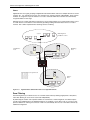
ROUTE HEALTH INJECTION ........................................................................ 17-1
CONFIGURATION EXAMPLE ........................................................................................................................17-1
HTTP HEALTH CHECK ALGORITHM ...........................................................................................................17-3
CONFIGURATION CONSIDERATIONS ............................................................................................................17-4
CLI SYNTAX .............................................................................................................................................17-4
GLOBAL CONFIG LEVEL ....................................................................................................................17-4
REAL SERVER LEVEL .........................................................................................................................17-4
INTERFACE LEVEL ..............................................................................................................................17-5
CONFIGURING THE HTTP HEALTH CHECK ON THE ROUTING SWITCH .........................................................17-5
CLI COMMANDS FOR 6308M-SX R1 .................................................................................................17-5
CLI COMMANDS FOR 9308M R2 ........................................................................................................17-6
CLI COMMANDS FOR 6308M-SX R3 ..................................................................................................17-7
DISPLAYING SERVER AND APPLICATION PORT INFORMATION ......................................................................17-7
DISPLAYING SERVER INFORMATION .....................................................................................................17-7
DISPLAYING KEEPALIVE INFORMATION .................................................................................................17-8
NETWORK MONITORING ..............................................................................A-1
RMON SUPPORT ...................................................................................................................................... A-1
STATISTICS (RMON GROUP 1) ............................................................................................................ A-1
HISTORY (RMON GROUP 2) ............................................................................................................... A-2
ALARM (RMON GROUP 3) .................................................................................................................. A-2
EVENT (RMON GROUP 9) ................................................................................................................... A-3
VIEWING SYSTEM INFORMATION ................................................................................................................. A-3
VIEWING CONFIGURATION INFORMATION ..................................................................................................... A-3
VIEWING PORT STATISTICS ........................................................................................................................ A-4
VIEWING STP STATISTICS .......................................................................................................................... A-4
CLEARING STATISTICS ............................................................................................................................... A-5
PROTECTING AGAINST DENIAL OF SERVICE ATTACKS..................................B-1
PROTECTING AGAINST SMURF ATTACKS ..................................................................................................... B-1
AVOIDING BEING AN INTERMEDIARY IN A SMURF ATTACK ...................................................................... B-2
AVOIDING BEING A VICTIM IN A SMURF ATTACK .................................................................................... B-2
PROTECTING AGAINST TCP SYN ATTACKS ................................................................................................ B-3
DISPLAYING STATISTICS ABOUT PACKETS DROPPED BECAUSE OF DOS ATTACKS ........................................ B-4
POLICIES AND FILTERS ...............................................................................C-1
SCOPE ...................................................................................................................................................... C-2
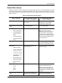
DEFAULT FILTER ACTIONS ......................................................................................................................... C-3
POLICY AND FILTER PRECEDENCE .............................................................................................................. C-4
QOS ................................................................................................................................................... C-4
PRECEDENCE AMONG FILTERS ON DIFFERENT LAYERS ........................................................................ C-4
PRECEDENCE AMONG FILTERS ON THE SAME LAYER ........................................................................... C-4
POLICIES ................................................................................................................................................... C-5
xvi
QUALITY-OF-SERVICE POLICIES ........................................................................................................... C-5
LAYER 3 POLICIES ............................................................................................................................... C-6
LAYER 4 POLICIES ............................................................................................................................... C-9
FILTERS .................................................................................................................................................. C-11
LAYER 2 FILTERS .............................................................................................................................. C-12
LAYER 3 FILTERS .............................................................................................................................. C-16
LAYER 4 FILTERS .............................................................................................................................. C-28
INDEX .......................................................................................................... I-1
xvii
Advanced Configuration and Management Guide
xviii
Chapter 1
Getting Started
Introduction
This guide describes how to install, configure, and monitor the following devices:
•
HP ProCurve Routing Switch 9308M
•
HP ProCurve Routing Switch 9304M
•
HP ProCurve Routing Switch 6308M-SX
•
HP ProCurve Switch 6208M-SX
This guide also describes how to monitor these products using statistics and summary screens.
Audience
This guide assumes that you have a working knowledge of Layer 2 and Layer 3 switching and routing. You also
should be familiar with the following protocols if applicable to your network—IP, RIP, OSPF, BGP4, IGMP, PIM,
DVMRP, IPX, AppleTalk, SRP, and VRRP.
Nomenclature
This guide uses the following typographical conventions:
Italic
highlights the title of another publication and occasionally emphasizes a word or phrase.
Bold
highlights a CLI command.
Bold Italic
highlights a term that is being defined.
Underline
highlights a link on the Web management interface.
Capitals
highlights field names and buttons that appear in the Web management interface.
NOTE: A note emphasizes an important fact or calls your attention to a dependency.
WARNING: A warning calls your attention to a possible hazard that can cause injury or death.
CAUTION:
A caution calls your attention to a possible hazard that can damage equipment.
1-1
Installation and Getting Started Guide
Terminology
The following table defines basic product terms used in this guide.
Product Terms
Term
chassis
Definition
A switch or routing switch that accepts optional modules or power supplies.
or
Chassis device
fixed-port device
A device that contains a fixed configuration of ports, instead of swappable
modules. The HP 6208M-SX switch and HP 6308M-SX routing switch are
fixed-port devices.
routing switch
A Layer 2 and Layer 3 device that switches and routes network traffic. The
term router is sometimes used in this document in descriptions of a routing
switch’s Layer 3 routing protocol features.
or
router
switch
A Layer 2 device that switches network traffic.
HP9300
An example Command Line Interface (CLI) prompt. Actual prompts show
the product number for the device, such as HP9304.
or
HP6208
or
HP6308
Related Publications
The following product documentation is available for your HP switch or routing switch:
1-2
•
Read Me First for the HP ProCurve Routing Switches 9304M, 9308M, and 6308M-SX, and the HP ProCurve
Switch 6208M-SX—This document includes software update information, the parts list for your HP ProCurve
device, and other product information. Updates to this document are published on the World Wide Web from
time to time, and may include additional troubleshooting, errata, and operating notes. To check for the latest
version of Read Me First, go to www.hp.com/go/hpprocurve, select Technical Support, and then Manuals.
•
Book 1: Installation and Getting Started Guide. Book 1 contains the product Safety and EMC Regulatory
statements as well as installation, security, and basic configuration information. A printed copy of this guide is
included with your HP product. An electronic copy is also included as a PDF (Portable Document Format) file
on the CD shipped with your HP product.
•
Book 2: Advanced Configuration and Management Guide. Book 2 contains advanced configuration
information for routing protocols, Spanning Tree Protocol (STP), Quality of Service (QoS), and Virtual LANs
(VLANs). In addition, appendixes in this guide contain reference information for network monitoring, policies
and filters, and software and hardware specifications. This manual is included in a PDF (Portable Document
Format) file on the CD shipped with your HP product.
•
Book 3: HP ProCurve Command Line Interface Reference. The Command Line Interface Reference
provides a dictionary of CLI commands and syntax. An electronic copy of this reference is included as a PDF
(Portable Document Format) file on the CD shipped with your HP product.
•
Documentation CD for the HP ProCurve Routing Switches 9304M, 9308M, 6308M-SX, and the HP
ProCurve Switch 6208M-SX—This CD contains PDF files for Book 1, Book 2, and Book 3, and provides a
Getting Started
method for electronically searching either individual chapters or an entire manual for specific topics. For a
brief description of the CD contents and how to use the CD to save time, do the following:
1.
Insert the CD in your PC’s CD-ROM drive.
2.
Using the file manager in your PC, select the drive containing the CD and display the CD’s directory.
3.
Use a compatible text editor to display the README.txt file in the CD’s root directory.
•
Manual Supplement—These documents are included with your HP device if the software shipped with the
device includes feature upgrades that were added after the last revision of the manual. They are also
included with software upgrades when available on the World Wide Web. To check for the latest software
version, go to www.hp.com/go/hpprocurve and click on Technical Support, then Software.
•
Support is as Close as the World Wide Web!—Included with your HP switch or routing switch, this
document is a guide to HP support services and also provides information on your HP networking product
warranty.
What’s New in this Edition?
This edition and the October 2000 editions of the Installation and Getting Started Guide and Command Line
Interface Reference contain descriptions of the new features listed below. (For features added in later, minor
releases – after November, 2000 – see the latest release notes in the Technical Support | Manuals area at
http://www.hp.com/go/hpprocurve.)
Enhancements Added in Software Release 06.6.X
The following enhancements are new in software release 06.6.X and higher. All of these enhancements also are
present in software release 07.1.X.
System-Level Enhancement
•
Secure management access based on VLAN ID
Enhancements Added in Software Release 07.1.X
The following enhancements are new in software release 07.1.X. These enhancements are present only in
software release 07.1.X. They are not supported in software release 06.6.X.
Layer 3 Enhancements
•
Support for up to 10,000 static ARP entries
•
Aggregate default network routes
•
Host-based IP load sharing for specific destination networks
•
ICMP Router Discovery Protocol (IRDP) enhancements
•
Option to disable ICMP redirect
•
RIP offset lists
•
More flexible IP multicast interface numbering
•
Hardware forwarding for all fragments of IP multicast packets
•
Multicast Source Discovery Protocol (MSDP)
•
Dynamic OSPF memory
•
Support for up to 32 OSPF area ranges in each area
•
Support for up to 25,000 External LSAs
•
OSPF group Link State Advertisement (LSA) pacing
•
External LSA reduction
1-3
Installation and Getting Started Guide
•
BGP4 re-advertises BGP routes even when OSPF or RIP routes to the same destination have a lower cost
•
Redistribution changes take place immediately
•
Option to redistribute Internal BGP (IBGP) routes into RIP and OSPF
•
Dynamic BGP4 route refresh
•
BGP4 route reflection updated to RFC 2796
•
Change to route map processing of ACL or other filtering deny statements
•
Option to clear BGP4 neighbor sessions based on a specific Autonomous System (AS) number.
•
You can specify a route map name when configuring BGP4 network information
•
Enhancements to set metric command in route maps
•
Enhancements to show ip bgp commands
•
Enhancement to BGP4 Syslog message
•
Network Address Translation (NAT)
•
Virtual Router Redundancy Protocol Extended (VRRPE)
•
ICMP Router Discovery Protocol (IRDP) is disabled by default
•
Policy-Based Routing (PBR)
•
Support for standard static IP routes and interface or null static routes to the same destination
•
Dynamic memory for BGP4
•
BGP4 peer groups
•
New BGP4 show commands
•
Enhanced BGP4 show commands for neighbor information
Layer 2 Enhancements
•
Updated STP port Path Cost defaults
•
Compatibility with Cisco Systems’ Per VLAN Spanning Tree (PVST)
System-Level Enhancements
1-4
•
Enhanced software version information
•
New strict mode for ACL processing of UDP traffic
•
Fixed Rate Limiting
•
Adaptive Rate Limiting
•
Denial of Service (DoS) protection for TCP SYN and ICMP transit traffic
•
Authorization and Accounting support for RADIUS and TACACS+
•
TACACS+ password prompt support
•
VLAN-based management access control
•
RSA authentication for SSH
•
SCP support for secure file transfers
•
Automatic load re-distribution following a healed trunk link
•
Support for up to 4095 VLANs and up to 4095 virtual interfaces (VEs)
•
VLAN and virtual interface groups
•
Enhanced CLI for managing redundant management modules
Getting Started
•
Super Aggregated VLANs
•
Support for simultaneous Telnet configuration by multiple users
•
New CLI command for displaying dynamic memory utilization
•
SNMP V2 view
•
Enhancement to show default values command
•
CLI enhancements to the startup-config and running-config files
•
Page display is configurable for individual CLI management sessions
•
CLI enhancement to display the idle time for open CLI sessions
•
New CLI command for displaying TACACS+ or RADIUS information
•
Enhancement to the show web command
•
New option for setting the timeout for Telnet sessions
•
Enhancements to show interface command
•
ACL configuration supported in the Web management interface
•
Greeting banners are displayed at the beginning of a Web management session
•
Increasing the Syslog buffer size does not clear entries
•
The newline character does not appear in Syslog and SNMP trap messages
•
New MIB tables for Adaptive Rate Limiting
•
Support for Secure Shell (SSH) for remote access to the CLI
•
Support up to 12 trunk groups on 24-port 10/100 modules
•
Strict ACL TCP mode
•
Support for per-port ACL assignment within a virtual interface’s VLAN
•
New commands for copying files between a device’s flash memory and a TFTP server
•
Change to the IP address used when you enable the routing switch to use a single IP address on the device
as the source for all Telnet, RADIUS, or TACACS/TACACS+ packets originated by the device
•
Option to suppress Telnet connection rejection message
•
Configurable block size for TFTP file transfers
Support and Warranty Information
Refer to Support is as Close as the World Wide Web, which was shipped with your HP switch or routing switch.
1-5
Installation and Getting Started Guide
1 - 6
Chapter 2
Quality of Service (QoS)
Software release 06.6.X provides the following enhancements to QoS on the HP 9304M, HP 9308M, and HP
6208M-SX routing switches.
•
You can choose between a strict queuing method and a weighted queuing method.
•
You can modify the minimum guaranteed percentage of bandwidth for each queue.
•
You can apply a QoS profile (one of the four queues) to 802.1q tagged VLAN packets.
•
You can display the percentage of an uplink’s bandwidth that each of a given set of ports uses. This is
especially useful in environments where collocated customers on different, isolated ports share common
uplink ports.
These new features add flexibility to the QoS features in earlier software releases but do not replace them.
The Queues
HP 9304M, HP 9308M, and HP 6208M-SX routing switches use the following queues:
•
qosp3 – The highest priority queue. This queue corresponds to 802.1p prioritization levels 6 and 7 and HP
priority levels 6 and 7.
•
qosp2 – The second-highest priority queue. This queue corresponds to 802.1p prioritization levels 4 and 5
and HP priority levels 4 and 5.
•
qosp1 – The third-highest priority queue. This queue corresponds to 802.1p prioritization levels 2 and 3 and
HP priority levels 2 and 3.
•
qosp0 – The lowest priority queue. This queue corresponds to 802.1p prioritization levels 0 and 1 and HP
priority levels 0 and 1.
The queue names listed above are the default names. You can rename the queues if you want, as described in
“Renaming the Queues” on page 2-4”.
2-1
Advanced Configuration and Management Guide
•
You can classify packets and assign them to specific queues based on the following criteria:
•
Incoming port (sometimes called ingress port)
•
IP source and destination addresses
•
Layer 4 source and destination information (for all IP addresses or specific IP addresses)
•
Static MAC entry
•
AppleTalk socket number
•
Layer 2 port-based VLAN membership
•
802.1q tag
By default, all the traffic types listed above except the 802.1q tagged packets are in the best effort queue, which is
the lowest priority queue. The 802.1q tagged packets are assigned to a queue based on the priority level (0 – 7)
in the packet’s tag. The default mapping of the priority levels to the queues is as follows.
Priority Level
Queue
6, 7
qosp3
4, 5
qosp2
2, 3
qosp1
0, 1
qosp0
In cases where a packet matches more than one traffic type, the highest queue level among the traffic type is
used. For example, if a tagged packet arrives on a tagged port and the 802.1p priority is 4 (qosp2) but the packet
contains IP source and destination information that matches an IP access policy configured to assign the traffic to
priority 7 (qosp3), the device places the packet in qosp3 of the outbound port.
Automatic Queue Mapping for IP Type Of Service (TOS) Values
HP devices that support QoS automatically examine the first two bits in the Type of Service (TOS) header in each
IP packet as it enters the device on a 10/100 port. The device then places the packet in the QoS queue that
corresponds to the TOS value.
The TOS value in the first two bits can be one of the following.
TOS value (binary)
Queue
11
qosp3
10
qosp2
01
qosp1
00
qosp0
As the packet moves through the system, if the packet matches other QoS allocations you have configured, the
packet is moved into a higher queue accordingly. For example, if the TOS values place the packet in qosp1, but
the packet is part of a port-based VLAN that is in qosp3, the packet enters queue qosp3. Packets can enter
higher queues but never enter lower queues as they move through the system.
2-2
Quality of Service (QoS)
Queuing Methods
In software release 06.6.X and higher, you can configure the device to use one of the following queuing methods:
•
Weighted – A weighted fair queuing algorithm is used to rotate service among the four queues. The rotation
is based on the weights you assign to each queue. This is the default queuing method and uses a default set
of queue weights. This method rotates service among the four queues, forwarding a specific number of
packets in one queue before moving on to the next one.
The number of packets serviced during each visit to a queue depends on the percentages you configure for
the queues. The software automatically converts the percentages you specify into weights for the queues.
•
Strict – The software assigns the maximum weights to each queue, to cause the queuing mechanism to serve
as many packets in one queue as possible before moving to a lower queue. This method biases the queuing
mechanism to favor the higher queues over the lower queues. For example, strict queuing processes as
many packets as possible in qosp3 before processing any packets in qosp2, then processes as many
packets as possible in qosp2 before processing any packets in qosp1, and so on.
Selecting the Queuing Method
The HP 9304M, HP 9308M, and HP 6208M-SX routing switches and the HP 6208M-SX switch use the weighted
fair queuing method of packet prioritization by default. To change the method to strict queuing or back to weighted
fair queuing, use one of the following methods.
USING THE CLI
To change the queuing method from weighted fair queuing to strict queuing, enter the following commands:
HP9300(config)# qos mechanism strict
HP9300(config)# write memory
Syntax: [no] qos mechanism strict | weighted
To change the method back to weighted fair queuing, enter the following commands:
HP9300(config)# qos mechanism weighted
HP9300(config)# write memory
USING THE WEB MANAGEMENT INTERFACE
1.
Log on to the device using a valid user name and password for read-write access. The System configuration
dialog is displayed.
2.
Click on the Weighted or Strict radio button next to QoS.
3.
Click the Apply button to save the change to the device’s running-config file.
4.
Select the Save link at the bottom of the dialog, then select Yes when prompted to save the configuration
change to the startup-config file on the device’s flash memory.
2-3
Advanced Configuration and Management Guide
Configuring the Queues
Each of the four queues has the following configurable parameters:
•
The queue name
•
The minimum percentage of a port’s outbound bandwidth guaranteed to the queue.
Renaming the Queues
The default queue names are qosp3, qosp2, qosp1, and qosp0. You can change one or more of the names if
desired. To do so, use one of the following methods.
USING THE CLI
To rename queue qosp3 (the premium queue) to “92-octane”, enter the following commands:
HP9300(config)# qos name qosp3 92-octane
HP9300(config)# write memory
Syntax: qos name <old-name> <new-name>
The <old-name> parameter specifies the name of the queue before the change.
The <new-name> parameter specifies the new name of the queue. You can specify an alphanumeric string up to
32 characters long.
USING THE WEB MANAGEMENT INTERFACE
2-4
1.
Log on to the device using a valid user name and password for read-write access. The System configuration
dialog is displayed.
2.
Click on the plus sign next to Configure in the tree view to expand the list of configuration options.
3.
Click on the plus sign next to QoS in the tree view to expand the list of QoS option links.
4.
Click on the Profile link to display the QoS Profile configuration panel, as shown in the following figure.
5.
Edit the strings name the Name fields for the queue(s) you want to rename. In this example, the premium
queue is renamed from “qosp3” to “92-octane”.
6.
Click the Apply button to save the change to the device’s running-config file.
7.
Select the Save link at the bottom of the dialog, then select Yes when prompted to save the configuration
change to the startup-config file on the device’s flash memory.
Quality of Service (QoS)
Changing the Minimum Bandwidth Percentages of the Queues
If you are using the weighted fair queuing mechanism instead of the strict mechanism, you can change the
weights for each queue by changing the minimum percentage of bandwidth you want each queue to guarantee for
its traffic.
By default, the four QoS queues receive the following minimum guaranteed percentages of a port’s total
bandwidth.
Queue
Default Minimum Percentage of Bandwidth
qosp3
80%
qosp2
15%
qosp1
3.3%
qosp0
1.7%
NOTE: The percentages are guaranteed minimum bandwidth percentages. Thus, they apply when a port is fully
utilized. When a port is not fully utilized, it is possible for queues to receive more than the configured percentage
of bandwidth. You cannot specify a maximum bandwidth percentage for a queue. Any queue can get more than
its committed share when other queues are idle.
When the queuing method is weighted fair queuing, the software internally translates the percentages into
weights. The weight associated with each queue controls how many packets are processed for the queue at a
given stage of a cycle through the weighted fair queuing algorithm.
For example, the default percentages shown above translate into the following weights.
Queue
Default Minimum Percentage
of Bandwidth
Queue Weight
qosp3
80%
4
qosp2
15%
3
qosp1
3.3%
2
qosp0
1.7%
1
A queue’s weight specifies how many packets are sent from the queue each time the queue is serviced. Thus,
when the default bandwidth percentages are used, four packets are sent from queue qosp3 each time the queue
is serviced, while three packets are sent from queue qosp2 each time it is serviced, and so on. The queuing
mechanism interleaves the queues during the cycle so that queue qosp3 is serviced after each visit to any other
queue. For example, using the default percentages (and thus the default weights), queue qosp3 receives 12 visits
for every one visit to queue qosp0.
2-5
Advanced Configuration and Management Guide
The following table shows one full queue cycle using the default bandwidth percentages.
qosp3
bandwidth % = 80
weight = 4
Total visits
Total
packets
qosp2
bandwidth % = 15
weight = 3
Total visits
Total
packets
1
4
1
2
8
2
3
12
4
16
5
20
4
6
24
5
7
28
8
32
9
36
7
10
40
8
11
44
12
48
2 - 6
1
qosp1
bandwidth % = 3.3
weight = 2
Total visits
Total
packets
qosp0
bandwidth % = 1.7
weight = 1
Total visits
Total
packets
3
1
2
6
1
3
2
9
1
1
Quality of Service (QoS)
Figure 2.1 illustrates a cycle through the queues.
q3 q3
q0
q2
q3 q3
q3 q3
q3 q3
q3 q3
q3 q3
q2
q2
Begin here
q3 q3
q3 q3
q3 q3
q3 q3
q2
q2
q3 q3
q3 q3
q3 q3
q3 q3
q2
q1
q3 q3
q3 q3
q3 q3
q3 q3
q2
q1
q3 q3
q3 q3
q3 q3
q3 q3
q2
q3 q3
q2
q3 q3
Queue 3: weight=4, minimum percentage=80%
Queue 2: weight=3, minimum percentage=15%
Queue 1: weight=2, minimum percentage=3.3%
Queue 0: weight=1, minimum percentage=1.7%
Figure 2.1
Example of a QoS cycle using the default weights
If you change the percentages for the queues, the software changes the weights, which changes the number of
visits a queue receives during a full queue cycle and also the number of packets sent from each queue during
each visit. For example, if you change the percentages so that queue qosp3 receives a weight of 5, then the
system processes five packets in that queue during each visit to the queue.
NOTE: The weighted fair queuing method is based on packet-level scheduling. As a result, a queue’s bandwidth
percentage does not necessarily reflect the exact bandwidth share the queue receives. This is due to the effects
of variable size packets.
2-7
Advanced Configuration and Management Guide
USING THE CLI
To change the minimum guaranteed bandwidth percentages of the queues, enter commands such as the
following. Note that this example uses the default queue names.
HP9300(config)# qos profile qosp3 75 qosp2 10 qosp1 10 qosp0 5
Profile qosp3
: PREMIUM
bandwidth requested 75% calculated
Profile qosp2
: HIGH
bandwidth requested 10% calculated
Profile qosp1
: NORMAL
bandwidth requested 10% calculated
Profile qosp0
: BEST-EFFORT bandwidth requested
5% calculated
HP9300(config)# write memory
75%
13%
8%
4%
Notice that the CLI displays the percentages you request and the percentages the device can provide based on
your request. The values are not always the same, as explained below.
Syntax: [no] qos profile <queue> <percentage> <queue> <percentage> <queue> <percentage>
<queue> <percentage>
Each <queue> parameter specifies the name of a queue. You can specify the queues in any order on the
command line, but you must specify each queue.
The <percentage> parameter specifies a number for the percentage of the device’s outbound bandwidth that are
allocating to the queue.
NOTE: The percentages you enter must equal 100. Also, the percentage for the premium queue (the highest
priority queue) must be at least 50.
If you enter percentages that are less than the minimum percentages supported for a queue, the CLI recalculates
the percentages to fall within the supported minimums. Here is an example. In this example, the values entered
for all but the best-effort queue (the lowest priority queue) are much lower than the minimum values supported for
those queues.
HP9300(config)# qos qosp3 1 qosp2 1 qosp1 2 qosp0 96
Warning - qosp3 bandwidth should be at least 50%
bandwidth scheduling mechanism: weighted priority
Profile qosp3
: PREMIUM
bandwidth requested
1%
Profile qosp2
: HIGH
bandwidth requested
1%
Profile qosp1
: NORMAL
bandwidth requested
2%
Profile qosp0
: BEST-EFFORT bandwidth requested 96%
calculated
calculated
calculated
calculated
50%
25%
13%
12% This example shows the warning message that is displayed if you enter a value that is less than 50% for the
premium queue. This example also shows the recalculations performed by the CLI. The CLI must normalize the
values because the weighted fair queuing algorithm and queue hardware require specific minimum bandwidth
allocations. You cannot configure the hardware to exceed the weighted fair queuing limitations.
The CLI normalizes the percentages you enter by increasing the percentages as needed for queues that have
less than the minimum percentage, converting the percentages to weights (which the weighted fair queuing
algorithm uses), and applying the following equations to calculate the percentages:
qosp3 = w3 / (w3 + 1)
qosp2 = (1 – qosp3) * w2 / (w2 + 1)
qosp1 = (1 – qosp3 – qosp2) * w1 / (w1 + 1)
qosp0 = 1 – qosp3 – qosp2 – qosp1
The value “w” stands for “weight”. Thus, these calculations determine the weights that the weighted fair queuing
algorithm will use for each queue.
For results that do not differ widely from the percentages you enter, enter successively lower percentages for each
queue, beginning with the premium queue. If you enter a higher percentage for a particular queue than you enter
for a higher queue, the normalized results can vary widely from the percentages you enter.
2-8
Quality of Service (QoS)
USING THE WEB MANAGEMENT INTERFACE
1.
Log on to the device using a valid user name and password for read-write access. The System configuration
dialog is displayed.
2.
Click on the plus sign next to Configure in the tree view to expand the list of configuration options.
3.
Click on the plus sign next to QoS in the tree view to expand the list of QoS option links.
4.
Click on the Profile link to display the QoS Profile configuration panel, as shown in the following figure.
5.
Edit the values in the Requested fields for the queue(s) you want to change. In this example, the following
minimum bandwidths are requested:
•
qosp0 – 5%
•
qosp1 – 10%
•
qosp2 – 10%
•
92-octane – 75%
NOTE: The percentages you enter must equal 100. Also, the percentage for the premium queue (the
highest priority queue) must be at least 50.
6.
Click the Apply button to save the changes to the device’s running-config file. Notice that the device
calculates the minimum bandwidth percentages that can be allocated to each of the queues based on your
percentage requests, and displays the actual percentages in the Calculated column. Here is an example.
2-9
Advanced Configuration and Management Guide
7.
Select the Save link at the bottom of the dialog, then select Yes when prompted to save the configuration
change to the startup-config file on the device’s flash memory.
Resetting the Minimum Bandwidth Percentages to Their Defaults
You can use either of the following CLI commands to reset the QoS queues to their default bandwidth percentages
(and therefore to their default weights).
USING THE CLI
Enter either of the following commands at the global CONFIG level:
•
qos mechanism weighted
•
no qos profile
USING THE WEB MANAGEMENT INTERFACE
You cannot reset the queue profiles to the default bandwidth percentages using the Web management interface.
Displaying the QoS Profile Configuration
To display the QoS settings, use either of the following methods.
USING THE CLI
To display the QoS settings for all the queues, enter the following command from any level of the CLI:
HP9300(config)# show qos-profiles all
bandwidth scheduling mechanism: weighted priority
Profile qosp3
: PREMIUM
bandwidth requested
Profile qosp2
: HIGH
bandwidth requested
Profile qosp1
: NORMAL
bandwidth requested
Profile qosp0
: BEST-EFFORT bandwidth requested
75%
10%
10%
5%
calculated
calculated
calculated
calculated
75%
13%
8%
4%
Syntax: show qos-profiles all | <name>
The all parameter displays the settings for all four queues. The <name> parameter displays the settings for the
specified queue.
USING THE WEB MANAGEMENT INTERFACE
1.
Log on to the device using a valid user name and password for read-write access. The System configuration
dialog is displayed.
2.
Click on the plus sign next to Configure in the tree view to expand the list of configuration options.
3.
Click on the plus sign next to QoS in the tree view to expand the list of QoS option links.
4.
Click on the Profile link to display the QoS Profile configuration panel.
2 - 10
Quality of Service (QoS)
Assigning QoS Priorities to Traffic
By default, traffic of the following categories is forwarded using the best-effort queue (qosp0):
•
Incoming port (sometimes called the ingress port)
•
Port-based VLAN membership
•
Static destination MAC entry
•
Layer 3 and Layer 4 information (IP and TCP/UDP source and destination information)
•
AppleTalk socket
NOTE: Tagged VLAN traffic is placed in a queue corresponding to the 802.1p priority in the tag by default. Thus,
if a tagged packet contains priority 7 in the tag (corresponding to the premium queue), the device places this
packet in the premium queue of the packet’s outbound port. You can change or remove the effect of the 802.1p
priority in the tags by reassigning the priority levels to different queues. See “Reassigning 802.1p Priorities to
Different Queues” on page 2-14.
Although it is possible for a packet to qualify for an adjusted QoS priority based on more than one of the criteria
above, the system always gives a packet the highest priority for which it qualifies. Thus, if a packet is entitled to
the premium queue because of its IP source and destination addresses, but is entitled only to the high queue because of its incoming port, the system places the packet in the premium queue on the outgoing port.
When you apply a QoS priority to one of the items listed above, you specify a number from
0 – 7. The number specifies the IEEE 802.1 equivalent to one of the four HP QoS queues. The numbers
correspond to the queues as follows.
Priority Level
Queue
6, 7
qosp3
4, 5
qosp2
2, 3
qosp1
0, 1
qosp0
The following sections describe how to change the priority for each of the items listed above.
Changing a Port’s Priority
To change a port’s QoS priority, use one of the following methods. The priority applies to outbound traffic on the
port.
USING THE CLI
To change the QoS priority of port 1/1 to the high queue (qosp2), enter the following commands:
HP9300(config)# interface ethernet 1/1
HP9300(config-if-1/1)# priority 5 HP9300(config-if-1/1)# write memory
Syntax: [no] priority <num>
The <num> parameter can be from 0 – 7 and specifies the IEEE 802.1 equivalent to one of the four QoS queues.
2 - 11
Advanced Configuration and Management Guide
USING THE WEB MANAGEMENT INTERFACE
1.
Log on to the device using a valid user name and password for read-write access. The System configuration
dialog is displayed.
2.
Click on the Port link to display the Port table.
3.
Scroll down to the port for which you want to change the QoS level, then click on the Modify button to the right
of the port information to display the Port configuration panel, as shown in the following example.
4.
Select a QoS level from 0 – 7 from the QoS field’s pulldown menu.
5.
Click the Apply button to save the change to the device’s running-config file.
6.
Select the Save link at the bottom of the dialog, then select Yes when prompted to save the configuration
change to the startup-config file on the device’s flash memory.
Changing a Layer 2 Port-Based VLAN’s Priority
By default, VLANs have priority 0 (the best effort queue, qosp0). To change a port-based VLAN’s QoS priority,
use one of the following methods. The priority applies to outbound traffic on ports in the VLAN.
NOTE: Tagged packets also contain a priority value in the 802.1q tag. If you use the default priority for a VLAN, a
tagged packet that exits on that VLAN can be placed into a higher priority queue based on the port priority, the
priority in the 802.1q tag, and so on. If you do not want the device to make priority decisions based on 802.1q
tags, you can change the priority for 802.1q tags on a VLAN basis. See “Reassigning 802.1p Priorities to Different
Queues” on page 2-14”.
USING THE CLI
To change the QoS priority of port-based VLAN 20 to the premium queue (qosp3), enter the following commands:
HP9300(config)# vlan 20
HP9300(config-vlan-20)# priority 7 HP9300(config-vlan-20)# write memory
Syntax: [no] priority <num>
The <num> parameter can be from 0 – 7 and specifies the IEEE 802.1 equivalent to one of the four QoS queues.
2 - 12
Quality of Service (QoS)
USING THE WEB MANAGEMENT INTERFACE
1.
Log on to the device using a valid user name and password for read-write access. The System configuration
dialog is displayed.
2.
Click on the plus sign next to Configure in the tree view to expand the list of configuration options.
3.
Click on the plus sign next to VLAN in the tree view to expand the list of VLAN option links.
4.
Click on the Port link to display the Port VLAN panel.
•
If you are adding a new port-based VLAN, click on the Add Port VLAN link to display the Port VLAN
configuration panel, as shown in the following example.
•
If you are modifying an existing port-based VLAN, click on the Modify button to the right of the row
describing the VLAN to display the Port VLAN configuration panel, as shown in the following example.
5.
Select a QoS level from 0 – 7 from the QoS field’s pulldown menu.
6.
If you are adding a new VLAN, click the Select Port Members button to display the Port Members dialog, as
shown in the following example.
7.
Select the ports you are placing in the VLAN. To select a row, click on the checkbox next to the row number,
then click on the Select Row button.
8.
When you finish selecting the ports, click on the Continue button to return to the Port VLAN configuration
dialog.
9.
Click the Add button (to add a new VLAN) or the Modify button (if you are modifying an existing VLAN) to
save the change to the device’s running-config file.
10. Select the Save link at the bottom of the dialog, then select Yes when prompted to save the configuration
change to the startup-config file on the device’s flash memory.
2 - 13
Advanced Configuration and Management Guide
Reassigning 802.1p Priorities to Different Queues
Tagged priority applies to tagged packets that come in from tagged ports. These packets have a tag in the header
that specifies the packet’s VLAN ID and its 802.1p priority tag value, which is 3 bits long.
By default, an HP device interprets the prioritization information in the 3-bit priority tag as follows.
Priority Level
Queue
6, 7
qosp3
4, 5
qosp2
2, 3
qosp1
0, 1
qosp0
This is the HP default interpretation for the eight prioritization values in every context (VLAN, static MAC entry, IP access policy, and so on). If the VLAN for the packet uses the default priority (0, equal to the qosp0 queue), then
the HP device uses the priority information in the packet to assign the packet to a queue on its incoming port. However, if the VLAN or the incoming port itself has a higher priority than the packet’s 802.1p priority, the HP
device uses the VLAN priority or incoming port priority, whichever is higher. You can specify how the HP device interprets the 3-bit priority information by reassigning the priority levels to other queues. For example, if you want the device to disregard the 802.1p priority and instead assign the priority
based on other items (VLAN, port, and so on), configure the device to set all the 802.1p priorities to the best-effort queue (qosp0). If a tagged packet’s 802.1p priority level is always in the qosp0 queue, then the packet’s outbound queue is affected by other items such as incoming port, VLAN, and so on.
To reassign the priorities to different queues, use either of the following methods.
USING THE CLI
To reassign all 802.1p priority levels 2 – 7 to the best-effort queue (qosp0), enter the following commands:
HP9300(config)#
HP9300(config)#
HP9300(config)#
HP9300(config)#
HP9300(config)#
HP9300(config)#
HP9300(config)#
qos tagged-priority
qos tagged-priority
qos tagged-priority
qos tagged-priority
qos tagged-priority
qos tagged-priority
write memory
2
3
4
5
6
7
qosp0
qosp0
qosp0
qosp0
qosp0
qosp0 Syntax: [no] qos tagged-priority <num> <queue>
The <num> parameter can be from 0 – 7 and specifies the IEEE 802.1 equivalent to one of the four QoS queues.
The <queue> parameter specifies the queue to which you are reassigning the priority level. You must specify one
of the named queues. The default names are qosp3, qosp2, qosp1, and qosp0. The example above reassigns
the 802.1p levels to queue qosp0. (There is no need to reassign levels 0 and 1 in this case, because they are
already assigned to qosp0 by default.)
USING THE WEB MANAGEMENT INTERFACE
1.
Log on to the device using a valid user name and password for read-write access. The System configuration
dialog is displayed.
2.
Click on the plus sign next to Configure in the tree view to expand the list of configuration options.
3.
Click on the plus sign next to QoS in the tree view to expand the list of QoS option links.
2 - 14
Quality of Service (QoS)
4. Click on the Bind link to display the QoS 802.1p to QoS Profile Binding configuration panel, as shown in the
following figure.
5.
For each priority level, select the QoS queue to which you want to reassign the profile by selecting the queue
name from the Profile field’s pulldown list. For example, to reassign priority 7 to QoS queue qosp0, select
qosp0 from the Profile Name field’s pulldown list in the row for priority 7.
6.
Click the Apply button to save the change to the device’s running-config file.
7.
Select the Save link at the bottom of the dialog, then select Yes when prompted to save the configuration
change to the startup-config file on the device’s flash memory.
Displaying the Queue Assignments for the 802.1p Priorities
To display the queues to which the 802.1p priorities are assigned, use either of the following methods.
USING THE CLI
To display the queue assignments for all the priorities, enter the following command at any level of the CLI:
HP9300(config)#
802.1p priority
802.1p priority
802.1p priority
802.1p priority
802.1p priority
802.1p priority
802.1p priority
802.1p priority
show priority-mapping all
0 mapped to qos profile qosp0
1 mapped to qos profile qosp0
2 mapped to qos profile qosp1
3 mapped to qos profile qosp1
4 mapped to qos profile qosp2
5 mapped to qos profile qosp2
6 mapped to qos profile qosp3
7 mapped to qos profile qosp3
In this example, the priorities still have their default queue assignments.
Syntax: show priority-mapping all | <num>
The all parameter displays the queue assignments for all the priorities. Alternatively, you can display the
assignment for a particular level by specifying the level number, as shown in the following example.
HP9300(config)# show priority-mapping 1
802.1p priority 1 mapped to qos profile qosp0
2 - 15
Advanced Configuration and Management Guide
USING THE WEB MANAGEMENT INTERFACE
1.
Log on to the device using a valid user name and password for read-write access. The System configuration
dialog is displayed.
2.
Click on the plus sign next to Configure in the tree view to expand the list of configuration options.
3.
Click on the plus sign next to QoS in the tree view to expand the list of QoS option links.
4. Click on the Bind link to display the QoS 802.1p to QoS Profile Binding configuration panel. The queue
assignments are listed for each of the eight priority levels.
Assigning Static MAC Entries to Priority Queues
By default, all MAC entries are in the best effort queue (qosp0). When you configure a static MAC entry, you can
assign the entry to a higher QoS level using either of the following methods.
USING THE CLI
To configure a static MAC entry and assign the entry to the premium queue, enter commands such as the
following:
HP9300(config)# vlan 9
HP9300(config-vlan-9)# static-mac-address 1145.1163.67FF e12 priority 7
HP9300(config)# write memory
Syntax: [no] static-mac-address <mac-addr> ethernet <portnum> [priority <num>]
[host-type | router-type]
The <num> parameter can be from 0 – 7 and specifies the IEEE 802.1 equivalent to one of the four QoS queues.
NOTE: On a routing switch, the static-mac-address command is at the port VLAN configuration level. On an HP
6208M-SX, the static-mac-address command is at the global CONFIG level.
USING THE WEB MANAGEMENT INTERFACE
1.
Log on to the device using a valid user name and password for read-write access. The System configuration
dialog is displayed.
2.
Click on the plus sign next to Configure in the tree view to expand the list of configuration options.
3.
Select the Static Station link to display the Static Station Table.
2 - 16
•
If the system already contains static MAC addresses and you are adding a new static MAC address, click
on the Add Static Station link to display the Static Station Table configuration panel, as shown in the
following example.
•
If you are modifying an existing static MAC address, click on the Modify button to the right of the row
describing the static MAC address to display the Static Station Table configuration panel, as shown in the
following example.
Quality of Service (QoS)
4.
Enter or edit the MAC address, if needed. Specify the address in the following format:
xx-xx-xx-xx-xx-xx.
5.
Change the VLAN number if needed by editing the value in the VLAN ID field.
6.
Select the port number from the Slot (for Chassis devices) and Port pulldown lists.
7.
Select a QoS level from 0 – 7 from the QoS field’s pulldown menu.
8.
Click the Add button (to add a new static MAC entry) or the Modify button (if you are modifying an existing
entry) to save the change to the device’s running-config file.
9.
Click the Apply button to save the change to the device’s running-config file.
10. Select the Save link at the bottom of the dialog, then select Yes when prompted to save the configuration
change to the startup-config file on the device’s flash memory.
Assigning IP and Layer 4 Sessions to Priority Queues
You can assign specific traffic flows to queues by configuring IP access policies. IP access policies allow you to
assign flows to priority queues based on any combination of the following criteria:
•
Source IP address
•
Destination IP address
•
Layer 4 type (TCP or UDP)
•
TCP or UDP port number
You configure IP access policies globally, then apply them to specific ports. QoS policies apply only to outbound
traffic, so you must apply the QoS polices to a port’s outbound direction instead of the port’s inbound direction.
To configure an IP access policy for assigning a traffic flow to a priority queue, use either of the following methods.
USING THE CLI
The CLI syntax differs between routing switches and switches. Examples and syntax are shown for both types of
devices.
Routing Switch Syntax
To assign a priority of 4 to all HTTP traffic on port 3/12 on an HP 9304M or HP 9308M routing switch, enter the
following:
HP9300(config)# ip access-policy 1 priority 4 any any tcp eq http
HP9300(config)# int e 3/12
HP9300(config-if-3/12)# ip access-policy-group out 1
Here is the syntax for routing switches.
Syntax: [no] ip access-policy <num> priority <0-7> <ip-addr> <ip-mask> | any
<ip-addr> <ip-mask> | any icmp | igmp | igrp | ospf | tcp | udp | <num> [<operator> [<tcp/udp-port-num>]]
Syntax: ip access-policy-group in | out <policy-list>
The <num> parameter is the policy number.
The priority <0-7> parameter specifies the QoS priority level. The default is 0 (best effort, qosp0). The highest
priority is 7 (premium, qosp3).
The <ip-addr> <ip-mask> | any <ip-addr> <ip-mask> | any parameters specify the source and destination IP
addresses. If you specify a particular IP address, you also need to specify the mask for that address. If you
specify any to apply the policy to all source or destination addresses, you do not need to specify any again for the
mask. Make sure you specify a separate address and mask or any for the source and destination address.
The icmp | igmp | igrp | ospf | tcp | udp | <num> parameter specifies the Layer 4 port to which you are applying
the policy. If you specify tcp or udp, you also can use the optional <operator> and <tcp/udp-port-num>
parameters to fine-tune the policy to apply to specific TCP or UDP ports.
2 - 17
Advanced Configuration and Management Guide
The <operator> parameter applies only if you use the tcp or udp parameter above. Use the <operator>
parameter to specify the comparison condition for the specific TCP or UDP ports. For example, if you are
configuring QoS for HTTP, specify tcp eq http. You can enter one of the following operators:
•
eq – The policy applies to the TCP or UDP port name or number you enter after eq.
•
gt – The policy applies to TCP or UDP port numbers greater than the port number or the numeric equivalent
of the port name you enter after gt.
•
lt – The policy applies to TCP or UDP port numbers that are less than the port number or the numeric
equivalent of the port name you enter after lt.
•
neq – The policy applies to all TCP or UDP port numbers except the port number or port name you enter after
neq.
•
range – The policy applies to all TCP or UDP port numbers that are between the first TCP or UDP port name
or number and the second one you enter following the range parameter. The range includes the port names
or numbers you enter. For example, to apply the policy to all ports between and including 23 (Telnet) and 53
(DNS), enter the following: range 23 53. The first port number in the range must be lower than the last
number in the range.
•
established – This operator applies only to TCP packets. If you use this operator, the QoS policy applies to
TCP packets that have the ACK (Acknowledgment) or RST (Reset) bits set on (set to “1”) in the Control Bits
field of the TCP packet header. Thus, the policy applies only to established TCP sessions, not to new
sessions. See Section 3.1, “Header Format”, in RFC 793 for information about this field.
The in parameter applies the policy to packets received in the port.
The out parameter applies the policy to packets sent on the port.
NOTE: To apply the policy to traffic in both directions, enter two ip access-policy-group commands, one
specifying the in parameter, and the other specifying the out parameter.
The <policy-list> parameter is a list of policy IDs.
NOTE: The device applies the policies in the order you list them, so make sure you order them in such a away
that you receive the results you expect. Once a packet matches a policy, the device takes the action specified in
that policy and stops comparing the packet to the policies in the list.
2 - 18
Quality of Service (QoS)
Figure 2.2 and Figure 2.3 show the CLI syntax for configuring a Layer 4 QoS policy on an HP routing switch.
<num> priority <num> <src-ip-addr> <ip-mask>|any <dst-ip-addr> <ip-mask>|any
ip access-policy
icmp
<CR>
igmp
<CR>
igrp
<CR>
ospf
<CR>
<num>
<CR>
tcp
eq
gt
lt
neq
bgp | dns |
ftp | http |
imap4 | ldap |
nntp | pop2 |
<CR>
pop3 | smtp |
ssl | telnet |
<num>
range
bgp | dns |
bgp | dns |
ftp | http |
ftp | http |
imap4 | ldap |
imap4 | ldap |
nntp | pop2 |
nntp | pop2 |
pop3 | smtp |
pop3 | smtp |
ssl | telnet |
ssl | telnet |
<num>
<num>
<CR>
eq
established
gt
lt
neq
bgp | dns |
ftp | http |
imap4 | ldap |
nntp | pop2 |
<CR>
pop3 | smtp |
<CR>
ssl | telnet |
<num>
range
<CR>
udp
Figure 2.2
bgp | dns |
bgp | dns |
ftp | http |
ftp | http |
imap4 | ldap |
imap4 | ldap |
nntp | pop2 |
nntp | pop2 |
pop3 | smtp |
pop3 | smtp |
ssl | telnet |
ssl | telnet |
<num>
<num>
<CR>
see the next page...
QoS IP policy syntax for an HP routing switch (1 of 2)
2 - 19
Advanced Configuration and Management Guide
continued from previous page
udp
eq
gt
bootpc | bootps |
lt
dns | tftp |
neq
ntp | radius |
<CR>
radius-old | rip |
snmp | snmp-trap |
<num>
range
ip access-policy-group
bootpc | bootps |
bootpc | bootps |
dns | tftp |
dns | tftp |
ntp | radius |
ntp | radius |
radius-old | rip |
radius-old | rip |
snmp | snmp-trap |
snmp | snmp-trap | <num>
<num>
in
<policy-list>
<CR>
<CR>
out
Figure 2.3
QoS IP policy syntax for an HP routing switch (2 of 2)
Switch Syntax
To assign a priority of 7 to FTP traffic on all ports on an HP 6208M-SX switch, enter the following commands:
HP6208(config)# ip policy 1 7 tcp ftp global
HP6208(config)# write memory
To assign a priority of 7 to HTTP traffic on ports 1 and 2 only, enter the following commands:
HP6208(config)# ip policy 2 7 tcp http local
HP6208(config)# int ethernet 1
HP6208(config-if-1)# ip-policy 2
HP6208(config-if-1)# int ethernet 2
HP6208(config-if-2)# ip-policy 2
HP6208(config)# write memory
Syntax: policy <num> priority <0-7> tcp | udp <tcp/udp-port-num> global | local
[no] ip-policy <num>
The <num> parameter is the policy number.
The priority <0-7> parameter specifies the QoS priority level. The default is 0 (best effort queue, qosp0). The
highest priority is 7 (premium, qosp3).
The tcp | udp <tcp/udp-port-num> parameter specifies the TCP or UDP port to which you are applying the policy.
The global and local parameters specify the scope of the policy:
•
If you specify global, the policy applies to all ports.
•
If you specify local, the policy will apply to the ports you specify. Use the following command on the Interface
level of the CLI to apply the policy to a port: ip-policy <num>
2 - 20
Quality of Service (QoS)
Figure 2.4 shows the CLI syntax for configuring a QoS policy on an HP switch. The value “<CR>” means
“carriage return”, also known as the Enter key.
ip policy
<num> priority
<num>
tcp
bgp
global
dns
local
<CR>
ftp
http
imap4
ldap
nntp
pop2
pop3
smtp
ssl
telnet
<num>
udp
bootpc
global
bootps
local
<CR>
dns
tftp
ntp
radius
radius-old
rip
snmp
snmp-trap
<num>
ip-policy
Figure 2.4
<num>
<CR>
QoS IP policy syntax for an HP switch
NOTE: The ip policy command allows you to configure global or local QoS policies. Use the ip-policy command
(note the difference between “ip policy” and “ip-policy”) at the Interface level of the CLI to apply a local policy to
a specific interface.
USING THE WEB MANAGEMENT INTERFACE
The Web management options for assigning QoS priorities to traffic flows differ between routing switches and
switches. Examples are shown for both types of devices.
2 - 21
Advanced Configuration and Management Guide
Routing Switch
To assign a priority of 4 to all HTTP traffic on port 3/12 on an HP 9304M or HP 9308M routing switch, perform the
following steps:
1.
Log on to the device using a valid user name and password for read-write access. The System configuration
dialog is displayed.
2.
Click on the plus sign next to Configure in the tree view to expand the list of configuration options.
3.
Click on the plus sign next to IP in the tree view to expand the list of IP option links.
4.
Click on the Access Policy link to display the IP Access Policy panel.
•
If the system already contains IP access policies and you are adding a new one, click on the Add IP
Access Policy link to display the IP Access Policy configuration panel, as shown in the following
example.
•
If you are modifying an existing IP access policy, click on the Modify button to the right of the row
describing the IP access policy to display the IP Access Policy configuration panel, as shown in the
following example.
5.
Enter the ID for the policy in the ID field.
6.
Select the QoS radio button next to Action.
7.
Select a QoS level from 0 – 7 from the QoS field’s pulldown menu. In this example, select 4.
8.
Enter the source IP address and network mask in the Source Address and Source Mask fields. To specify
“any” for a field, leave all four zeros in the field. In this example, leave the zeros.
9.
Enter the destination IP address and network mask in the Destination Address and Destination Mask fields.
To specify “any” for a field, leave all four zeroes in the field. In this example, leave the zeros.
10. If you want the policy to apply only to packets containing specific types of Layer 4 traffic, enter the protocol in
the Protocol field. You can enter the protocol’s Layer 4 port number or one of the following well-known
names:
2 - 22
•
icmp
•
igmp
•
igrp
Quality of Service (QoS)
•
ospf
•
tcp
•
udp
In this example, enter tcp.
11. If you entered tcp or udp, you also can select one of the following comparison operators from the Operator
field.
•
Equal – The policy applies to the TCP or UDP port name or number you enter in the TCP/UDP port field.
In this example, select Equal.
•
Greater – The policy applies to TCP or UDP port numbers greater than the port number or the numeric
equivalent of the port name you enter in the TCP/UDP port field.
•
Less – The policy applies to TCP or UDP port numbers that are less than the port number or the numeric
equivalent of the port name you enter in the TCP/UDP port field.
•
Not Equal – The policy applies to all TCP or UDP port numbers except the port number or port name you
enter in the TCP/UDP port field.
12. If you entered tcp or udp in the Protocol field, enter the TCP or UDP port number in the TCP/UDP port field.
In this example, enter 80 (the well-known port for HTTP).
13. If you entered tcp in the Protocol field and you want the policy to apply to TCP sessions that are already in
effect, click on the checkbox next to Established. If you select this option, the QoS policy applies to TCP
packets that have the ACK (Acknowledgment) or RST (Reset) bits set on (set to “1”) in the Control Bits field of
the TCP packet header. Thus, the policy applies only to established TCP sessions, not to new sessions. See
Section 3.1, “Header Format”, in RFC 793 for information about this field.
NOTE: This option applies only to destination TCP ports, not to source TCP ports.
14. Click the Add button (to add a new policy) or the Modify button (if you are modifying an existing policy) to save
the policy to the device’s running-config file.
15. Select the Access Policy Group link to display the Access Policy Group panel.
•
If the system already contains IP access policy groups and you are adding a new one, click on the Add IP
Access Policy Group link to display the IP Access Policy Group configuration panel, as shown in the
following example.
•
If you are modifying an existing IP access policy, click on the Modify button to the right of the row
describing the IP access policy group to display the IP Access Policy Group configuration panel, as
shown in the following example.
16. Select the port number from the Slot (for Chassis devices) and Port pulldown lists. In this example, select 3/
12.
2 - 23
Advanced Configuration and Management Guide
17. Click the checkbox next to In Filter, Out Filter, or next to both options to indicate the traffic direction to which
you are applying the policy.
•
The In Filter option applies the policy to packets received in the port.
•
The Out Filter option applies the policy to packets sent on the port.
•
If you select both, the policy applies to traffic in both directions.
In this example, select Out Filter.
18. Enter the policy IDs in the Filter ID List field.
NOTE: The device applies the policies in the order you list them, so make sure you order them in such a
way that you receive the results you expect. Once a packet matches a policy, the device takes the action
specified in that policy and stops comparing the packet to the policies in the list.
19. Click the Add button to apply the change to the device’s running-config file.
20. Select the Save link at the bottom of the dialog, then select Yes when prompted to save the configuration
change to the startup-config file on the device’s flash memory.
NOTE: You also can access the dialog for saving configuration changes by clicking on Command in the tree
view, then clicking on Save to Flash.
Switch
To assign a priority of 7 to FTP traffic on all ports on an HP 6208M-SX switch, perform the following steps:
1.
Log on to the device using a valid user name and password for read-write access. The System configuration
dialog is displayed.
2.
Select the Layer 4 QoS link to display the QoS panel.
3.
Enter the ID for the policy in the ID field.
4.
Select the Switch or Port radio button next to Scope to indicate whether the policy applies globally or only to
certain ports.
5.
Select a QoS level from 0 – 7 from the QoS field’s pulldown menu. In this example, select 7.
6.
Select the UDP or TCP radio button next to Protocol to specify the type of traffic to which the QoS policy
applies.
7.
Select a well-known TCP or UDP port name (depending on whether you selected TCP or UDP) from the TCP/
UDP Port field’s pulldown list. To enter a port number instead, click on the User Define button to change the
field into an entry field, then enter the port number. For this example, select FTP.
8.
Click the Add button to apply the change to the device’s running-config file.
9.
If you selected Port in step 4, click on Port QoS to display the Port QoS panel. Otherwise, go to step 13.
10. Select the port number from the Slot (for Chassis devices) and Port pulldown lists.
11. Enter the policy IDs in the QoS ID List field.
NOTE: The device applies the policies in the order you list them, so make sure you order them in such a
away that you receive the results you expect. Once a packet matches a policy, the device takes the action
specified in that policy and stops comparing the packet to the policies in the list.
12. Click the Add button to apply the change to the device’s running-config file.
13. Select the Save link at the bottom of the dialog, then select Yes when prompted to save the configuration
change to the startup-config file on the device’s flash memory.
2 - 24
Quality of Service (QoS)
Assigning AppleTalk Sockets to Priority Queues
By default, all AppleTalk sockets are in the best effort queue (qosp0). To assign an AppleTalk socket to a higher
priority queue, use either of the following methods.
USING THE CLI
To assign socket 123 to the premium queue, enter the following commands:
HP9300(config)# appletalk qos socket 123 priority 7
HP9300(config)# write memory
Syntax: [no] appletalk qos socket <num> priority <num>
The first <num> parameter specifies the socket number.
The second <num> parameter can be from 0 – 7 and specifies the IEEE 802.1 equivalent to one of the four QoS
queues.
USING THE WEB MANAGEMENT INTERFACE
1.
Log on to the device using a valid user name and password for read-write access. The System configuration
dialog is displayed.
2.
If AppleTalk is not already enabled, enable it by selecting the Enable radio button next to AppleTalk, then
clicking Apply.
3.
Click on the plus sign next to Configure in the tree view to expand the list of configuration options.
4.
Click on the plus sign next to AppleTalk in the tree view to expand the list of AppleTalk option links.
5.
Click on the Socket QoS link to display the AppleTalk Socket QoS panel, as shown in the following example.
6.
Edit the socket number in the Socket field if needed.
7.
Select a QoS level from 0 – 7 from the QoS field’s pulldown menu.
8.
Click on the Apply button to apply the new QoS setting to the socket number specified in the Socket field or
click on the Apply To All Sockets button to apply the new QoS setting to all AppleTalk sockets.
9.
Select the Save link at the bottom of the dialog, then select Yes when prompted to save the configuration
change to the startup-config file on the device’s flash memory.
2 - 25
Advanced Configuration and Management Guide
Configuring a Utilization List for an Uplink Port
You can configure uplink utilization lists that display the percentage of a given uplink port’s bandwidth that is used
by a specific list of downlink ports. The percentages are based on 30-second intervals of RMON packet statistics
for the ports. Both transmit and receive traffic is counted in each percentage.
NOTE: This feature is intended for ISP or collocation environments in which downlink ports are dedicated to
various customers’ traffic and are isolated from one another. If traffic regularly passes between the downlink
ports, the information displayed by the utilization lists does not provide a clear depiction of traffic exchanged by the
downlink ports and the uplink port.
Each uplink utilization list consists of the following:
•
Utilization list number (1, 2, 3, or 4)
•
One or more uplink ports
•
One or more downlink ports
Each list displays the uplink port and the percentage of that port’s bandwidth that was utilized by the downlink
ports over the most recent 30-second interval.
You can configure up to four bandwidth utilization lists. To do so, use either of the following methods.
USING THE CLI
To configure an uplink utilization list, enter commands such as the following. The commands in this example
configure a link utilization list with port 1/1 as the uplink port and ports 1/2 and 1/3 as the downlink ports.
HP9300(config)# relative-utilization 1 uplink eth 1/1 downlink eth 1/2 to 1/3
HP9300(config)# write memory
Syntax: [no] relative-utilization <num> uplink ethernet <portnum> [to <portnum> | <portnum>…]
downlink ethernet <portnum> [to <portnum> | <portnum>…]
The <num> parameter specifies the list number. You can configure up to four lists. Specify a number from 1 – 4.
The uplink ethernet parameters and the port number(s) you specify after the parameters indicate the uplink
port(s).
The downlink ethernet parameters and the port number(s) you specify after the parameters indicate the downlink
port(s).
USING THE WEB MANAGEMENT INTERFACE
1.
Log on to the device using a valid user name and password for read-write access. The System configuration
dialog is displayed.
2.
Click on the plus sign next to Configure in the tree view to expand the list of configuration options.
3.
Click on the Port link to display the Port Configuration panel.
2 - 26
Quality of Service (QoS)
4.
Click on the Relative Utilization link at the top of the panel to display the Port Uplink Relative Utilization panel,
as shown in the following example:
5.
Enter the ID for the link utilization list in the ID field. You can specify a number from 1 – 4.
6.
Click the Select Uplink Port Members button. A Port Members panel similar to the following is displayed.
7.
Select the boxes next to the ports you want to include in the uplink list. When you have finished, click
Continue.
8.
On the Port Uplink Relative Utilization panel, click the Select Downlink Port Members button to display a Port
Members panel for downlink ports.
9.
Select the boxes next to the ports you want to include in the downlink list. When you have finished, click
Continue.
10. On the Port Uplink Relative Utilization panel, click the Add button create the uplink utilization list.
11. Select the Save link at the bottom of the dialog, then select Yes when prompted to save the configuration
change to the startup-config file on the device’s flash memory.
2 - 27
Advanced Configuration and Management Guide
Displaying Utilization Percentages for an Uplink
After you configure an uplink utilization list, you can display the list to observe the percentage of the uplink’s
bandwidth that each of the downlink ports used during the most recent 30-second port statistics interval. The
number of packets sent and received between the two ports is listed, as well as the ratio of each individual
downlink port’s packets relative to the total number of packets on the uplink.
To display uplink utilization percentages, use either of the following methods.
USING THE CLI
To display an uplink utilization list, enter a command such as the following at any level of the CLI:
HP9300(config)# show relative-utilization 1 uplink: ethe 1
30-sec total uplink packet count = 3011
packet count ratio (%)
1/ 2:60
1/ 3:40
In this example, ports 1/2 and 1/3 are sending traffic to port 1/1. Port 1/2 and port 1/3 are isolated (not shared by
multiple clients) and typically do not exchange traffic with other ports except for the uplink port, 1/1.
Syntax: show relative-utilization <num>
The <num> parameter specifies the list number.
NOTE: The example above represents a pure configuration in which traffic is exchanged only by ports 1/2 and
1/1, and by ports 1/3 and 1/1. For this reason, the percentages for the two downlink ports equal 100%. In some
cases, the percentages do not always equal 100%. This is true in cases where the ports exchange some traffic
with other ports in the system or when the downlink ports are configured together in a port-based VLAN.
In the following example, ports 1/2 and 1/3 are in the same port-based VLAN.
HP9300(config)# show relative-utilization 1 uplink: ethe 1
30-sec total uplink packet count = 3011
packet count ratio (%)
1/ 2:100
1/ 3:100
Here is another example showing different data for the same link utilization list. In this example, port 1/2 is
connected to a hub and is sending traffic to port 1/1. Port 1/3 is unconnected.
HP9300(config)# show relative-utilization 1 uplink: ethe 1
30-sec total uplink packet count = 2996
packet count ratio (%)
1 /2:100
1/ 3:---
2 - 28
Quality of Service (QoS)
USING THE WEB MANAGEMENT INTERFACE
1.
Log on to the device using a valid user name and password for read-write access. The System configuration
dialog is displayed.
2.
Click on the plus sign next to Configure in the tree view to expand the list of configuration options.
3.
Click on the Port link to display the Port Configuration panel.
4.
Click on the Relative Utilization link at the top of the panel to display the Port Uplink Relative Utilization panel.
5.
Click on the Show link. A panel listing the configured uplink utilization lists is displayed:
6.
Click on the ID of an uplink utilization list to display utilization percentages for the ports in the list.
This panel displays a graph of the percentage of the uplink’s bandwidth that each of the downlink ports used
during the most recent 30-second port statistics interval.
2 - 29
Advanced Configuration and Management Guide
2 - 30
Chapter 3
Using Access Control Lists (ACLs)
Access control lists (ACLs) enable you to permit or deny packets based on source and destination IP address,
IP protocol information, or TCP or UDP protocol information. You can configure the following types of ACLs:
•
Standard – Permits or denies packets based on source IP address. Valid standard ACL IDs are 1 – 99 or a
string.
•
Extended – Permits or denies packets based on source and destination IP address and also based on IP
protocol information. Valid extended ACL IDs are a number from 100 – 199 or a string.
This chapter also describes Policy-Based Routing (PBR), a feature that allows you to use ACLs and route maps to
selectively modify and route IP packets based on their source IP address.
NOTE: This chapter describes IP forwarding ACLs and management access ACLs only. For information about
ACLs used for BGP4 filtering, see “Configuring BGP4” on page 10-1.
NOTE: For optimal performance, apply deny ACLs to inbound ports instead of outbound ports. This way, traffic
is dropped as it tries to enter the HP device, instead of being dropped after it has been forwarded internally to the
outbound port.
NOTE: Outbound ACLs do not filter broadcast traffic or any traffic (including ICMP replies) generated by the HP
device itself.
Overview
The following section describes ACLs. To configure ACLs, go to the following sections:
•
“Disabling or Re-Enabling Access Control Lists (ACLs)” on page 3-4
•
“Configuring Standard ACLs” on page 3-5
•
“Configuring Extended ACLs” on page 3-9
•
“Configuring Named ACLs” on page 3-18
•
“Modifying ACLs” on page 3-19
•
“Applying an ACL to a Subset of Ports on a Virtual Interface” on page 3-21
•
“Enabling Strict TCP or UDP Mode” on page 3-21
•
“Displaying ACLs” on page 3-23
3-1
Installation and Getting Started Guide
•
“Displaying the Log Entries” on page 3-23
•
“Policy-Based Routing (PBR)” on page 3-24
Usage Guidelines for Access Control Lists (ACLs)
This section provides some guidelines for implementing ACLs to ensure wire-speed ACL performance.
For optimal ACL performance, use the following guidelines:
•
Apply ACLs to inbound traffic rather than outbound traffic.
•
Use the default filtering behavior as much as possible. For example, if you are concerned with filtering only a
few specific addresses, create deny entries for those addresses, then create a single entry to permit all other
traffic. For tighter control, create explicit permit entries and use the default deny action for all other
addresses.
•
Use deny ACLs sparingly. When a deny ACL is applied to an interface, the software sends all packets sent or
received on the interface (depending on the traffic direction of the ACL) to the CPU for examination.
•
Adjust system resources if needed:
•
If IP traffic is going to be high, increase the size of the IP forwarding cache to allow more routes. To do
so, use the system-max ip-cache <num> command at the global CONFIG level of the CLI.
•
If much of the IP traffic you are filtering is UDP traffic, increase the size of the session table to allow more
ACL sessions. To do so, use the system-max session-limit <num> command at the global CONFIG
level of the CLI.
Avoid the following implementations when possible:
•
Do not apply ACLs to outbound traffic. The system creates separate inbound ACLs to ensure that an
outbound ACL is honored for traffic that normally would be forwarded to other ports.
•
Do not enable the strict TCP ACL mode unless you need it for tighter security.
•
Avoid ICMP-based ACLs where possible. If you are interested in providing protection against ICMP Denial of
Service (DoS) attacks, use HP’s DoS protection features. See “Protecting Against Denial of Service Attacks”
on page B-1.
If the IP traffic in your network is characterized by a high volume of short sessions, this also can affect ACL
performance, since this traffic initially must go to the CPU. All ICMP ACLs go to the CPU, as do all TCP SYN,
SYN/ACK, FIN, and RST packets and the first UDP packet of a session.
ACL Support on the HP Products
HP ACLs have two basic types of uses:
•
Filtering forwarded traffic through the device – described in this chapter
•
Controlling management access to the device itself – described in the “Securing Access” chapter in the
Installation and Getting Started Guide
ACL IDs and Entries
ACLs consist of ACL IDs and ACL entries:
•
ACL ID – An ACL ID is a number from 1 – 99 (for a standard ACL) or 100 – 199 (for an extended ACL) or a
character string. The ACL ID identifies a collection of individual ACL entries. When you apply ACL entries to
an interface, you do so by applying the ACL ID that contains the ACL entries to the interface, instead of
applying the individual entries to the interface. This makes applying large groups of access filters (ACL
entries) to interfaces simple.
NOTE: This is different from IP access policies. If you use IP access policies, you apply the individual
policies to interfaces.
3-2
Using Access Control Lists (ACLs)
•
ACL entry – An ACL entry is a filter command associated with an ACL ID. The maximum number of ACL
entries you can configure is a system-wide parameter and depends on the device you are configuring. You
can configure up to the maximum number of entries in any combination in different ACLs. The total number of
entries in all ACLs cannot exceed the system maximum.
NOTE: Up to 1024 entries are supported on routing switches.
You configure ACLs on a global basis, then apply them to the incoming or outgoing traffic on specific ports. You
can apply only one ACL to a port’s inbound traffic and only one ACL to a port’s outbound traffic. The software
applies the entries within an ACL in the order they appear in the ACL’s configuration. As soon as a match is found,
the software takes the action specified in the ACL entry (permit or deny the packet) and stops further comparison
for that packet.
Default ACL Action
The default action when no ACLs are configured on a device is to permit all traffic. However, once you configure
an ACL and apply it to a port, the default action for that port is to deny all traffic that is not explicitly permitted on
the port.
•
If you want to tightly control access, configure ACLs consisting of permit entries for the access you want to
permit. The ACLs implicitly deny all other access.
•
If you want to secure access in environments with many users, you might want to configure ACLs that consist
of explicit deny entries, then add an entry to permit all access to the end of each ACL. The software permits
packets that are not denied by the deny entries.
NOTE: The software generates log entries only when packets are explicitly denied by ACLs. The software does
not generate log entries for explicitly permitted entries or for entries that are implicitly denied.
NOTE: Do not apply an empty ACL (an ACL ID without any corresponding entries) to an interface. If you
accidentally do this, the software applies the default ACL action, deny all, to the interface and thus denies all
traffic.
Controlling Management Access to the Device
You can use standard ACLs to control Telnet, Web, and SNMP access to a device. See the “Securing Access”
chapter in the Installation and Getting Started Guide.
ACL Logging
ACL logging is disabled by default. However, when you configure an ACL entry, you can enable logging for that
entry by adding the log parameter to the end of the CLI command for the entry.
When you enable logging for an ACL entry, statistics for packets that match the deny conditions of the ACL entry
are logged. For example, if you configure a standard ACL entry to deny all packets from source address
209.157.22.26, statistics for packets that are explicitly denied by the ACL entry are logged in the HP device’s
Syslog buffer and in SNMP traps sent by the device.
The first time an ACL entry denies a packet, the software immediately generates a Syslog entry and SNMP trap.
The software also starts a five-minute timer. The timer keeps track of all packets explicitly denied by the ACL
entries. After five minutes, the software generates a single Syslog entry for each ACL entry that has denied a
packet. The message indicates the number of packets denied by the ACL entry during the previous five minutes.
If no ACL entries explicitly deny packets during an entire five-minute timer interval, the timer stops. The timer
restarts when an ACL entry explicitly denies a packet.
NOTE: The timer for logging packets denied by Layer 2 filters is separate.
The following sections describe how to configure standard and extended ACLs.
3-3
Installation and Getting Started Guide
NOTE: The following sections describe how to configure ACLs using the HP device’s CLI. You also can create
and modify ACLs using a text editor on a file server, then copy them to the device’s running-config file. In fact, this
method is a convenient way to reorder individual ACL entries within an ACL. See “Modifying ACLs” on page 3-19.
Disabling or Re-Enabling Access Control Lists (ACLs)
A routing switch cannot actively use both IP access policies and ACLs for filtering IP traffic. When you boot a
routing switch with software release 06.6.x or higher, the software checks the device’s startup-config file for ip
access-policy-group commands, which associate IP access policies with ports. If the software finds an ip
access-policy-group command in the file, the software disables all packet-forwarding ACLs (those associated
with specific ports) and also prevents you from applying an ACL to a port.
The next time you save the startup-config file, the software adds the following command near the top of the file,
underneath the ver (software version) statement:
ip dont-use-acl
This command disables all packet-forwarding ACLs (those associated with specific ports) and also prevents you
from associating an ACL with a port. However, the command does not remove existing ACLs from the startup
config file. In addition, the command does not affect ACLs used for controlling management access to the device.
Enabling ACL Mode
If you try to apply an ACL to a port when the ACL mode is disabled (when the ip dont-use-acl command is in
effect), a message is displayed, as shown in the following CLI example:
HP9300(config-if-e1000-1/1)# ip access-group 1 out
Must enable ACL mode first by using no ip dont-use-acl command and removing all ip access-policy-group commands from interfaces, write memory and reload
As the message states, if you want to use ACLs, you must first enable the ACL mode. To do so, use either of the
following methods.
USING THE CLI
To enable the ACL mode, enter the following commands:
HP9300(config-if-e1000-1/1)# exit
HP9300(config)# no ip dont-use-acl
HP9300(config)# write memory
HP9300(config)# end
HP9300# reload
The write memory command removes the ip dont-use-acl command from the startup-config file. The reload
command reloads the software. When the software finishes loading, you can apply ACLs to ports.
The commands that configure the IP access policies and apply them to ports remain in the startup-config file in
case you want to use them again, but they are disabled. If you later decide you want to use the IP access policies
again instead of ACLs, you must disable the ACL mode again. See the following section.
USING THE WEB MANAGEMENT INTERFACE
3-4
1.
Log on to the device using a valid user name and password for read-write access. The System configuration
panel is displayed.
2.
Click on the plus sign next to Configure in the tree view to expand the list of configuration options.
3.
Click on the plus sign next to IP in the tree view to expand the list of IP option links.
4.
Click on the General link to display the IP configuration panel.
5.
Select the Enable radio button next to Access Control List.
6.
Click the Apply button to save the change to the device’s running-config file.
Using Access Control Lists (ACLs)
7.
Select the Save link at the bottom of the dialog. Select Yes when prompted to save the configuration change
to the startup-config file on the device’s flash memory.
Disabling ACL Mode
If the ACL mode is enabled, a message is displayed when you try to apply an IP access policy to a port, as shown
in the following CLI example:
HP9300(config-if-e1000-1/1)# ip access-policy-group 1 in
Must disable ACL mode first by using ip dont-use-acl command, write memory and reload
To use the IP access policies, you first must disable the ACL mode using either of the following methods.
USING THE CLI
To disable the ACL mode, enter the following commands:
HP9300(config-if-e1000-1/1)# exit
HP9300(config)# ip dont-use-acl
HP9300(config)# write memory
HP9300(config)# end
HP9300# reload
USING THE WEB MANAGEMENT INTERFACE
1.
Log on to the device using a valid user name and password for read-write access. The System configuration
panel is displayed.
2.
Click on the plus sign next to Configure in the tree view to expand the list of configuration options.
3.
Click on the plus sign next to IP in the tree view to expand the list of IP option links.
4.
Click on the General link to display the IP configuration panel.
5.
Select the Disable radio button next to Access Control List.
6.
Click the Apply button to save the change to the device’s running-config file.
7.
Select the Save link at the bottom of the dialog. Select Yes when prompted to save the configuration change
to the startup-config file on the device’s flash memory.
Configuring Standard ACLs
This section describes how to configure standard ACLs with numeric IDs.
•
For configuration information on named ACLs, see “Configuring Named ACLs” on page 3-18.
•
For configuration information on extended ACLs, see “Configuring Extended ACLs” on page 3-9.
Standard ACLs permit or deny packets based on source IP address. You can configure up to 99 standard ACLs.
You can configure up to 1024 individual ACL entries on a device. There is no limit to the number of ACL entries an
ACL can contain except for the system-wide limitation of 1024 total ACL entries.
USING THE CLI
To configure a standard ACL and apply it to outgoing traffic on port 1/1, enter the following commands.
HP9300(config)# access-list 1 deny host 209.157.22.26 log
HP9300(config)# access-list 1 deny 209.157.29.12 log
HP9300(config)# access-list 1 deny host IPHost1 log
HP9300(config)# access-list 1 permit any HP9300(config)# int eth 1/1
HP9300(config-if-1/1)# ip access-group 1 out HP9300(config)# write memory
3-5
Installation and Getting Started Guide
The commands in this example configure an ACL to deny packets from three source IP addresses from being
forwarded on port 1/1. The last ACL entry in this ACL permits all packets that are not explicitly denied by the first
three ACL entries.
Standard ACL Syntax
Syntax: [no] access-list <num> deny | permit <source-ip> | <hostname> <wildcard> [log]
or
Syntax: [no] access-list <num> deny | permit <source-ip>/<mask-bits> | <hostname> [log]
Syntax: [no] access-list <num> deny | permit host <source-ip> | <hostname> [log]
Syntax: [no] access-list <num> deny | permit any [log]
Syntax: [no] ip access-group <num> in | out
The <num> parameter is the access list number and can be from 1 – 99.
The deny | permit parameter indicates whether packets that match a policy in the access list are denied
(dropped) or permitted (forwarded).
The <source-ip> parameter specifies the source IP address. Alternatively, you can specify the host name.
NOTE: To specify the host name instead of the IP address, the host name must be configured using the HP
device’s DNS resolver. To configure the DNS resolver name, use the ip dns server-address… command at the
global CONFIG level of the CLI.
The <wildcard> parameter specifies the mask value to compare against the host address specified by the
<source-ip> parameter. The <wildcard> is a four-part value in dotted-decimal notation (IP address format)
consisting of ones and zeros. Zeros in the mask mean the packet’s source address must match the <source-ip>.
Ones mean any value matches. For example, the <source-ip> and <wildcard> values 209.157.22.26 0.0.0.255
mean that all hosts in the Class C sub-net 209.157.22.x match the policy.
If you prefer to specify the wildcard (mask value) in CIDR format, you can enter a forward slash after the IP
address, then enter the number of significant bits in the mask. For example, you can enter the CIDR equivalent of
“209.157.22.26 0.0.0.255” as “209.157.22.26/24”. The CLI automatically converts the CIDR number into the
appropriate ACL mask (where zeros instead of ones are the significant bits) and changes the non-significant
portion of the IP address into ones. For example, if you specify 209.157.22.26/24 or 209.157.22.26 0.0.0.255,
then save the changes to the startup-config file, the value appears as 209.157.22.0/24 (if you have enabled
display of sub-net lengths) or 209.157.22.0 0.0.0.255 in the startup-config file.
If you enable the software to display IP sub-net masks in CIDR format, the mask is saved in the file in
“/<mask-bits>” format. To enable the software to display the CIDR masks, enter the ip show-subnet-length
command at the global CONFIG level of the CLI. You can use the CIDR format to configure the ACL entry
regardless of whether the software is configured to display the masks in CIDR format.
NOTE: If you use the CIDR format, the ACL entries appear in this format in the running-config and startup-config
files, but are shown with sub-net mask in the display produced by the
show access-list and show ip access-list commands. The host <source-ip> | <hostname> parameter lets you specify a host IP address or name. When you use this
parameter, you do not need to specify the mask. A mask of all zeros (0.0.0.0) is implied.
The any parameter configures the policy to match on all host addresses.
The log argument configures the device to generate Syslog entries and SNMP traps for packets that are denied
by the access policy.
3-6
Using Access Control Lists (ACLs)
NOTE: You can enable logging on ACLs and filters that support logging even when the ACLs and filters are
already in use. To do so, re-enter the ACL or filter command and add the log parameter to the end of the ACL or
filter. The software replaces the ACL or filter command with the new one. The new ACL or filter, with logging
enabled, takes effect immediately.
The in | out parameter specifies whether the ACL applies to incoming traffic or outgoing traffic on the interface to
which you apply the ACL. You can apply the ACL to an Ethernet port or virtual interface.
NOTE: If the ACL is for the inbound traffic direction on a virtual routing interface, you also can specify a subset of
ports within the VLAN containing that interface when assigning an ACL to the interface. See “Configuring Named
ACLs” on page 3-18.
USING THE WEB MANAGEMENT INTERFACE
To configure a standard ACL:
1.
Log on to the device using a valid user name and password for read-write access. The System configuration
dialog is displayed.
2.
Click on the plus sign next to Configure in the tree view to display the list of configuration options.
3.
Click on the plus sign next to System or IP to display more configuration options. You can access the ACL
configuration panels from either location.
4.
Select the Standard ACL link.
5.
•
If the device does not already have some standard ACLs, the Standard ACL configuration panel is
displayed, as shown in the following example.
•
Otherwise, if the device already has some standard ACLs, the Standard ACL table is displayed. This
table lists the configured ACLs. Select the Add Standard ACL link to display the Standard ACL
configuration panel, as shown in the following example.
Change the ACL number in the Standard ACL Number field or use the ACL number displayed in the field.
NOTE: You cannot specify a name.
6.
Select the ACL action. You can select Permit or Deny:
•
Permit – Forwards traffic or allows management access for the specified IP source.
•
Deny – Drops traffic or denies management access for the specified IP source.
3-7
Installation and Getting Started Guide
NOTE: If the ACL is a forwarding ACL, the action forwards or drops the traffic. If the ACL is a management
access ACL, the action permits or denies management access.
7.
Enter the source information. You can enter the source IP address and network mask or the host name.
•
If you enter the address, you also must enter the network mask. To specify “any”, enter “0.0.0.0”.
•
If you enter a host name instead of an IP address, when you click Add to add the ACL, the Web
management interface sends a DNS query for the address. For the query to be successful, the device
must have network access to a DNS server and the server must have an Address record for the host. In
addition, the device must be configured with a DNS domain name and the IP address of the DNS server.
8.
If you specified the Deny action, optionally enable logging by selecting the Log checkbox. If you enable
logging for this ACL entry, the software generates Syslog entries for traffic that the ACL denies.
9.
Select the IP Access Group link from the tree view.
•
If the device does not already have some ACLs applied to interfaces, the IP Access Group configuration
panel is displayed, as shown in the following example.
•
Otherwise, if the device already has some ACLs applied to interfaces, the IP Access Group table is
displayed. Select the Add link to display the IP Access Group configuration panel, as shown in the
following example.
10. Select the Slot (if you are configuring a Chassis device) and port from the Slot and Port pulldown menus.
11. Specify the traffic direction to which the ACL applies. You can select one or both of the following:
•
In Bound – The ACL applies to traffic received on the port from other devices.
•
Out Bound – The ACL applies to traffic this HP device queues for transmission on the port.
12. Enter the ACL number in the ACL Number field.
NOTE: You cannot specify a named ACL.
13. Click the Add button to save the ACL and the association of the ACL with an interface to the device’s running
config file.
14. Select the Save link at the bottom of the dialog. Select Yes when prompted to save the configuration change
to the startup-config file on the device’s flash memory.
NOTE: You also can access the dialog for saving configuration changes by clicking on Command in the tree
view, then clicking on Save to Flash.
3-8
Using Access Control Lists (ACLs)
Configuring Extended ACLs
This section describes how to configure extended ACLs.
•
For configuration information on named ACLs, see “Configuring Named ACLs” on page 3-18.
•
For configuration information on standard ACLs, see “Configuring Standard ACLs” on page 3-5.
Extended ACLs let you permit or deny packets based on the following information:
•
IP protocol
•
Source IP address or host name
•
Destination IP address or host name
•
Source TCP or UDP port (if the IP protocol is TCP or UDP)
•
Destination TCP or UDP port (if the IP protocol is TCP or UDP)
The IP protocol can be one of the following well-known names or any IP protocol number from
0 – 255:
•
Internet Control Message Protocol (ICMP)
•
Internet Group Management Protocol (IGMP)
•
Internet Gateway Routing Protocol (IGRP)
•
Internet Protocol (IP)
•
Open Shortest Path First (OSPF)
•
Transmission Control Protocol (TCP)
•
User Datagram Protocol (UDP)
For TCP and UDP, you also can specify a comparison operator and port name or number. For example, you can
configure a policy to block web access to a specific website by denying all TCP port 80 (HTTP) packets from a
specified source IP address to the website’s IP address.
USING THE CLI
To configure an extended access list that blocks all Telnet traffic received on port 1/1 from IP host 209.157.22.26,
enter the following commands.
HP9300(config)# access-list 101 deny tcp host 209.157.22.26 any eq telnet log HP9300(config)# access-list 101 permit ip any any HP9300(config)# int eth 1/1
HP9300(config-if-1/1)# ip access-group 101 in HP9300(config)# write memory
Here is another example of commands for configuring an extended ACL and applying it to an interface. These
examples show many of the syntax choices. Notice that some of the entries are configured to generate log entries
while other entries are not thus configured.
HP9300(config)#
HP9300(config)#
HP9300(config)#
HP9300(config)#
HP9300(config)#
HP9300(config)#
access-list
access-list
access-list
access-list
access-list
access-list
102
102
102
102
102
102
perm icmp 209.157.22.0/24 209.157.21.0/24
deny igmp host rkwong 209.157.21.0/24 log
deny igrp 209.157.21.0/24 host rkwong log
deny ip host 209.157.21.100 host 209.157.22.1 log
deny ospf any any log permit ip any any The first entry permits ICMP traffic from hosts in the 209.157.22.x network to hosts in the 209.157.21.x network.
The second entry denies IGMP traffic from the host device named “rkwong” to the 209.157.21.x network.
The third entry denies IGRP traffic from the 209.157.21.x network to the host device named “rkwong”.
3-9
Installation and Getting Started Guide
The fourth entry denies all IP traffic from host 209.157.21.100to host 209.157.22.1 and generates Syslog entries
for packets that are denied by this entry.
The fifth entry denies all OSPF traffic and generates Syslog entries for denied traffic.
The sixth entry permits all packets that are not explicitly denied by the other entries. Without this entry, the ACL
would deny all incoming or outgoing IP traffic on the ports to which you assign the ACL.
The following commands apply ACL 102 to the incoming and outgoing traffic on port 1/2 and to the incoming traffic
on port 4/3.
HP9300(config)# int eth 1/2
HP9300(config-if-1/2)# ip access-group 102 in HP9300(config-if-1/2)# ip access-group 102 out HP9300(config-if-1/2)# exit HP9300(config)# int eth 4/3
HP9300(config-if-4/3)# ip access-group 102 in HP9300(config)# write memory
Here is another example of an extended ACL.
HP9300(config)#
HP9300(config)#
HP9300(config)#
neq 5
HP9300(config)#
HP9300(config)#
access-list 103 deny tcp 209.157.21.0/24 209.157.22.0/24 access-list 103 deny tcp 209.157.21.0/24 eq ftp 209.157.22.0/24 access-list 103 deny tcp 209.157.21.0/24 209.157.22.0/24 lt telnet access-list 103 deny udp any range 5 6 209.157.22.0/24 range 7 8
access-list 103 permit any any The first entry in this ACL denies TCP traffic from the 209.157.21.x network to the 209.157.22.x network.
The second entry denies all FTP traffic from the 209.157.21.x network to the 209.157.22.x network.
The third entry denies TCP traffic from the 209.157.21.x network to the 209.157.22.x network, if the TCP port
number of the traffic is less than the well-known TCP port number for Telnet (23), and if the TCP port is not equal
to 5. Thus, TCP packets whose TCP port numbers are 5 or are greater than 23 are allowed.
The fourth entry denies UDP packets from any source to the 209.157.22.x network, if the UDP port number from
the source network is 5 or 6 and the destination UDP port is 7 or 8.
The fifth entry permits all packets that are not explicitly denied by the other entries. Without this entry, the ACL
would deny all incoming or outgoing IP traffic on the ports to which you assign the ACL.
The following commands apply ACL 103 to the incoming and outgoing traffic on ports 2/1 and 2/2.
HP9300(config)# int eth 2/1
HP9300(config-if-2/1)# ip access-group
HP9300(config-if-2/1)# ip access-group
HP9300(config-if-2/1)# exit HP9300(config)# int eth 2/2
HP9300(config-if-2/2)# ip access-group
HP9300(config-if-2/2)# ip access-group
HP9300(config)# write memory
103 in 103 out 103 in
103 out Filtering on IP Precedence and TOS Values
To configure an extended IP ACL that matches based on IP precedence, enter commands such as the following:
HP9300(config)# access-list 103 deny tcp 209.157.21.0/24 209.157.22.0/24 precedence internet HP9300(config)# access-list 103 deny tcp 209.157.21.0/24 eq ftp 209.157.22.0/24 precedence 6 HP9300(config)# access-list 103 permit any any The first entry in this ACL denies TCP traffic from the 209.157.21.x network to the 209.157.22.x network, if the
traffic has the IP precedence option “internet” (equivalent to “6”).
3 - 10
Using Access Control Lists (ACLs)
The second entry denies all FTP traffic from the 209.157.21.x network to the 209.157.22.x network, if the traffic
has the IP precedence value “6” (equivalent to “internet”).
The third entry permits all packets that are not explicitly denied by the other entries. Without this entry, the ACL
would deny all incoming or outgoing IP traffic on the ports to which you assign the ACL.
To configure an IP ACL that matches based on TOS, enter commands such as the following:
HP9300(config)# access-list 104 deny tcp 209.157.21.0/24 209.157.22.0/24 tos normal HP9300(config)# access-list 104 deny tcp 209.157.21.0/24 eq ftp 209.157.22.0/24 tos
13 HP9300(config)# access-list 104 permit any any The first entry in this IP ACL denies TCP traffic from the 209.157.21.x network to the 209.157.22.x network, if the
traffic has the IP TOS option “normal” (equivalent to “0”).
The second entry denies all FTP traffic from the 209.157.21.x network to the 209.157.22.x network, if the traffic
has the IP precedence value “13” (equivalent to “max-throughput”, “min-delay”, and “min-monetary-cost”).
The third entry permits all packets that are not explicitly denied by the other entries. Without this entry, the ACL
would deny all incoming or outgoing IP traffic on the ports to which you assign the ACL.
Extended ACL Syntax
Syntax: access-list <num> deny | permit <ip-protocol> <source-ip> | <hostname> <wildcard> [<operator>
<source-tcp/udp-port>] <destination-ip> | <hostname> <wildcard> [<operator> <destination-tcp/udp-port>]
[precedence <name> | <num>] [tos <name> | <num>] [log]
Syntax: [no] access-list <num> deny | permit host <ip-protocol> any any [log]
Syntax: [no] ip access-group <num> in | out
The <num> parameter indicates the ACL number and be from 100 – 199 for an extended ACL.
The deny | permit parameter indicates whether packets that match the policy are dropped or forwarded.
The <ip-protocol> parameter indicates the type of IP packet you are filtering. You can specify one of the following:
•
icmp
•
igmp
•
igrp
•
ip
•
ospf
•
tcp
•
udp
•
<protocol-number>
The <source-ip> | <hostname> parameter specifies the source IP host for the policy. If you want the policy to
match on all source addresses, enter any.
The <wildcard> parameter specifies the portion of the source IP host address to match against. The <wildcard> is
a four-part value in dotted-decimal notation (IP address format) consisting of ones and zeros. Zeros in the mask
mean the packet’s source address must match the <source-ip>. Ones mean any value matches. For example,
the <source-ip> and <wildcard> values 209.157.22.26 0.0.0.255 mean that all hosts in the Class C sub-net
209.157.22.x match the policy.
If you prefer to specify the wildcard (mask value) in Classless Interdomain Routing (CIDR) format, you can enter a
forward slash after the IP address, then enter the number of significant bits in the mask. For example, you can
enter the CIDR equivalent of “209.157.22.26 0.0.0.255” as “209.157.22.26/24”. The CLI automatically converts
the CIDR number into the appropriate ACL mask (where zeros instead of ones are the significant bits) and
changes the non-significant portion of the IP address into zeros. For example, if you specify 209.157.22.26/24 or
3 - 11
Installation and Getting Started Guide
209.157.22.26 0.0.0.255, then save the changes to the startup-config file, the value appears as 209.157.22.0/24
(if you have enabled display of sub-net lengths) or 209.157.22.0 0.0.0.255 in the startup-config file.
If you enable the software to display IP sub-net masks in CIDR format, the mask is saved in the file in
“/<mask-bits>” format. To enable the software to display the CIDR masks, enter the ip show-subnet-length
command at the global CONFIG level of the CLI. You can use the CIDR format to configure the ACL entry
regardless of whether the software is configured to display the masks in CIDR format.
NOTE: If you use the CIDR format, the ACL entries appear in this format in the running-config and startup-config
files, but are shown with sub-net mask in the display produced by the show access-list and show ip access-list
commands.
The <destination-ip> | <hostname> parameter specifies the destination IP host for the policy. If you want the
policy to match on all destination addresses, enter any.
The <operator> parameter specifies a comparison operator for the TCP or UDP port number. This parameter
applies only when you specify tcp or udp as the IP protocol. For example, if you are configuring an entry for
HTTP, specify tcp eq http. You can enter one of the following operators:
•
eq – The policy applies to the TCP or UDP port name or number you enter after eq.
•
gt – The policy applies to TCP or UDP port numbers greater than the port number or the numeric equivalent
of the port name you enter after gt.
•
lt – The policy applies to TCP or UDP port numbers that are less than the port number or the numeric
equivalent of the port name you enter after lt.
•
neq – The policy applies to all TCP or UDP port numbers except the port number or port name you enter after
neq.
•
range – The policy applies to all TCP or UDP port numbers that are between the first TCP or UDP port name
or number and the second one you enter following the range parameter. The range includes the port names
or numbers you enter. For example, to apply the policy to all ports between and including 23 (Telnet) and 53
(DNS), enter the following: range 23 53. The first port number in the range must be lower than the last
number in the range.
•
established – This operator applies only to TCP packets. If you use this operator, the policy applies to TCP
packets that have the ACK (Acknowledgment) or RST (Reset) bits set on (set to “1”) in the Control Bits field of
the TCP packet header. Thus, the policy applies only to established TCP sessions, not to new sessions. See
Section 3.1, “Header Format”, in RFC 793 for information about this field.
NOTE: This operator applies only to destination TCP ports, not source TCP ports.
The <tcp/udp-port> parameter specifies the TCP or UDP port number or well-known name. The device
recognizes the following well-known names. For other ports, you must specify the port number.
NOTE: The following lists are organized alphabetically. In the CLI, these port names are listed according to
ascending port number.
•
3 - 12
TCP port names recognized by the software:
•
bgp
•
dns
•
ftp
•
http
•
imap4
•
ldap
•
nntp
Using Access Control Lists (ACLs)
•
•
pop2
•
pop3
•
smtp
•
ssl
•
telnet
UDP port names recognized by the software:
•
bootps
•
bootpc
•
dns
•
ntp
•
radius
•
radius-old
•
rip
•
snmp
•
snmp-trap
•
tftp
The in | out parameter specifies whether the ACL applies to incoming traffic or outgoing traffic on the interface to
which you apply the ACL. You can apply the ACL to an Ethernet port or virtual interface.
NOTE: If the ACL is for the inbound traffic direction on a virtual routing interface, you also can specify a subset of
ports within the VLAN containing that interface when assigning an ACL to the interface. See “Configuring Named
ACLs” on page 3-18.
The precedence <name> | <num> parameter of the ip access-list command specifies the IP precedence. The
precedence option for of an IP packet is set in a three-bit field following the four-bit header-length field of the
packet’s header. You can specify one of the following:
•
critical or 5 – The ACL matches packets that have the critical precedence. If you specify the option number
instead of the name, specify number 5.
•
flash or 3 – The ACL matches packets that have the flash precedence. If you specify the option number
instead of the name, specify number 3.
•
flash-override or 4 – The ACL matches packets that have the flash override precedence. If you specify the
option number instead of the name, specify number 4.
•
immediate or 2 – The ACL matches packets that have the immediate precedence. If you specify the option
number instead of the name, specify number 2.
•
internet or 6 – The ACL matches packets that have the internetwork control precedence. If you specify the
option number instead of the name, specify number 6.
•
network or 7 – The ACL matches packets that have the network control precedence. If you specify the option
number instead of the name, specify number 7.
•
priority or 1 – The ACL matches packets that have the priority precedence. If you specify the option number
instead of the name, specify number 1.
•
routine or 0 – The ACL matches packets that have the routine precedence. If you specify the option number
instead of the name, specify number 0.
The tos <name> | <num> parameter of the ip access-list command specifies the IP TOS.
3 - 13
Installation and Getting Started Guide
You can specify one of the following:
•
max-reliability or 2 – The ACL matches packets that have the maximum reliability TOS. The decimal value
for this option is 2.
•
max-throughput or 4 – The ACL matches packets that have the maximum throughput TOS. The decimal
value for this option is 4.
•
min-delay or 8 – The ACL matches packets that have the minimum delay TOS. The decimal value for this
option is 8.
•
min-monetary-cost or 1 – The ACL matches packets that have the minimum monetary cost TOS. The
decimal value for this option is 1.
•
normal or 0 – The ACL matches packets that have the normal TOS. The decimal value for this option is 0.
•
<num> – A number from 0 – 15 that is the sum of the numeric values of the options you want. The TOS field
is a four-bit field following the Precedence field in the IP header. You can specify one or more of the following.
To select more than one option, enter the decimal value that is equivalent to the sum of the numeric values of
all the TOS options you want to select. For example, to select the max-reliability and min-delay options, enter
number 10. To select all options, select 15.
The log parameter enables SNMP traps and Syslog messages for packets denied by the ACL.
NOTE: You can enable logging on ACLs and filters that support logging even when the ACLs and filters are
already in use. To do so, re-enter the ACL or filter command and add the log parameter to the end of the ACL or
filter. The software replaces the ACL or filter command with the new one. The new ACL or filter, with logging
enabled, takes effect immediately.
USING THE WEB MANAGEMENT INTERFACE
To configure an extended ACL:
1.
Log on to the device using a valid user name and password for read-write access. The System configuration
dialog is displayed.
2.
Click on the plus sign next to Configure in the tree view to display the list of configuration options.
3.
Click on the plus sign next to System or IP to display more configuration options. You can access the ACL
configuration panels from either location.
4.
Select the Extended ACL link.
3 - 14
•
If the device does not already have some extended ACLs, the Extended ACL configuration panel is
displayed, as shown in the following example.
•
Otherwise, if the device already has some extended ACLs, the Extended ACL table is displayed. This
table lists the configured ACLs. Select the Add Extended ACL link to display the Extended ACL
configuration panel, as shown in the following example.
Using Access Control Lists (ACLs)
5.
Change the ACL number in the ACL Number field or use the ACL number displayed in the field.
NOTE: You cannot specify a name.
6.
7.
Select the ACL action. You can select Permit or Deny:
•
Permit – Forwards traffic that matches the ACL.
•
Deny – Drops traffic that matches the ACL.
Enter the source IP information. You can enter the source IP address and network mask or the host name.
•
If you enter the address, you also must enter the network mask. To specify “all”, enter “0.0.0.0”.
•
If you enter a host name instead of an IP address, when you click Add to add the ACL, the Web
management interface sends a DNS query for the address. For the query to be successful, the device
3 - 15
Installation and Getting Started Guide
must have network access to a DNS server and the server must have an Address record for the host. In
addition, the device must be configured with a DNS domain name and the IP address of the DNS server.
8.
Enter the destination IP information. The options and requirements are the same as those for entering the
source IP information.
9.
Select the IP precedence from the IP Precedence pulldown menu (optional). The precedence option for of an
IP packet is set in a three-bit field following the four-bit header-length field of the packet’s header. You can
select one of the following:
•
routine – The ACL matches packets that have the routine precedence.
•
priority – The ACL matches packets that have the priority precedence.
•
immediate – The ACL matches packets that have the immediate precedence.
•
flash – The ACL matches packets that have the flash precedence.
•
flash-override – The ACL matches packets that have the flash override precedence.
•
critical – The ACL matches packets that have the critical precedence.
•
internet – The ACL matches packets that have the internetwork control precedence.
•
network – The ACL matches packets that have the network control precedence.
•
none – The ACL does not use the IP precedence as part of the comparison when filtering.
10. Select the Type of Service (TOS) from the TOS menu (optional). You can select one or more of the following:
•
normal – The ACL matches packets that have the normal TOS.
•
min-monetary-cost or – The ACL matches packets that have the minimum monetary cost TOS.
•
max-reliability – The ACL matches packets that have the maximum reliability TOS.
•
max-throughput – The ACL matches packets that have the maximum throughput TOS.
•
min-delay – The ACL matches packets that have the minimum delay TOS.
NOTE: To select more than one TOS option, hold the CTRL key while selecting each option.
11. If you specified the Deny action, optionally enable logging by selecting the Log checkbox. If you enable
logging for this ACL entry, the software generates Syslog entries for traffic that the ACL denies.
12. Specify the IP protocol. You can specify the protocol by name or by number.
•
To specify the IP protocol by name, select the By Name radio button, then select the protocol from the
pulldown menu. You can select one of the following: icmp, igmp, igrp, ip, ospf, tcp, udp.
•
To specify the IP protocol by number, select the By Number radio button, then enter the decimal number
of the protocol.
13. If you specified “tcp” or “udp” for the IP protocol, use the following steps to configure the source and
destination TCP or UDP options. Otherwise, go to Step 18.
14. Select the Established checkbox if you selected the TCP protocol and you want the ACL to apply to
established TCP sessions after you apply the ACL to an interface. Specifically, if you select this option, the
ACL applies to TCP packets that have the ACK (Acknowledgment) or RST (Reset) bits set on (set to “1”) in
the Control Bits field of the TCP packet header. If you do not select this option, the ACL applies only to
sessions that begin after you apply the ACL to an interface.
15. Select the comparison operator for the source TCP or UDP port. You can select one of the following:
3 - 16
•
Equal – The ACL applies to the TCP or UDP port you specify in the next step.
•
NotEqual – The ACL applies to all TCP or UDP ports except the port you specify in the next step.
•
LessThan – The ACL applies to TCP or UDP ports whose numbers are less than the number of the port
you specify in the following step.
Using Access Control Lists (ACLs)
•
GreaterThan – The ACL applies to TCP or UDP ports whose numbers are greater than the number of the
port you specify in the following step.
NOTE: The comparison operators apply only when you are filtering on individual source and destination
TCP or UDP ports. If you are filtering on a range of ports, the operators do not apply. Instead, the ACL
matches on any TCP or UDP port that is equal to a port within the specified range.
16. Specify the source TCP or UDP port. You can specify a single port or a range of ports.
•
To specify a single port, select the radio button next to Single Port. Enter the port number in the Port
field. Alternatively, you can select a well-known port name. To do so, select the Source Port System
Defined button to change the port number entry field into a pulldown menu containing well-known port
names. Select the port from the pulldown menu.
•
To specify a port range, select the radio button next to Port Range. Enter the low port number in the
range in the Low Port field and the high port number in the HighPort field. Alternatively, select the Source
Range System Defined button to change the entry fields into pulldown menus containing well-known
names. Even if you specify the ports by name, you still must select the lower-numbered port first, then
select the higher-numbered port.
17. Specify the destination TCP or UDP port. You can specify a single port or a range of ports. The procedures
and requirements are the same as those for selecting the source TCP or UDP port. See the previous step.
18. Select the IP Access Group link from the tree view.
•
If the device does not already have some ACLs applied to interfaces, the IP Access Group configuration
panel is displayed, as shown in the following example.
•
Otherwise, if the device already has some ACLs applied to interfaces, the IP Access Group table is
displayed. Select the Add link to display the IP Access Group configuration panel, as shown in the
following example.
19. Select the Slot (if you are configuring a Chassis device) and port from the Slot and Port pulldown menus.
20. Specify the traffic direction to which the ACL applies. You can select one or both of the following:
•
In Bound – The ACL applies to traffic received on the port from other devices.
•
Out Bound – The ACL applies to traffic this HP device queues for transmission on the port.
21. Enter the ACL number in the ACL Number field.
NOTE: You cannot specify a named ACL.
22. Click the Add button to save the ACL and the association of the ACL with an interface to the device’s running
config file.
23. Select the Save link at the bottom of the dialog. Select Yes when prompted to save the configuration change
to the startup-config file on the device’s flash memory.
3 - 17
Installation and Getting Started Guide
NOTE: You also can access the dialog for saving configuration changes by clicking on Command in the tree
view, then clicking on Save to Flash.
Configuring Named ACLs
When you configure an IP ACL, you can refer to the ACL by a numeric ID or by a name.
•
If you refer to the ACL by a numeric ID, you can use 1 – 99 for a standard ACL or 100 – 199 for an extended
ACL.
•
If you refer to the ACL by a name, you specify whether the ACL is a standard ACL or an extended ACL, then
specify the name.
You can configure up to 100 named standard IP ACLs and 100 named extended IP ACLs. You also can configure
up to 100 standard ACLs and 100 extended ACLs by number. Regardless of how many ACLs you have, the
device can have a maximum of 1024 ACL entries, associated with the ACLs in any combination. (On HP 9304M
or HP 9308M Chassis devices with Management II modules, the maximum is 2048.)
To configure a named IP ACL, use the following CLI method.
USING THE CLI
The commands for configuring named ACL entries are different from the commands for configuring numbered
ACL entries. The command to configure a numbered ACL is access-list. The command for configuring a named
ACL is ip access-list. In addition, when you configure a numbered ACL entry, you specify all the command
parameters on the same command. When you configure a named ACL, you specify the ACL type (standard or
extended) and the ACL number with one command, which places you in the configuration level for that ACL. Once
you enter the configuration level for the ACL, the command syntax is the same as the syntax for numbered ACLs.
The following examples show how to configure a named standard ACL entry and a named extended ACL entry.
Configuration Example for Standard ACL
To configure a named standard ACL entry, enter commands such as the following.
HP9300(config)# ip access-list standard Net1 HP9300(config-std-nac1)# deny host 209.157.22.26 log
HP9300(config-std-nac1)# deny 209.157.29.12 log
HP9300(config-std-nac1)# deny host IPHost1 log
HP9300(config-std-nac1)# permit any HP9300(config-std-nac1)# exit HP9300(config)# int eth 1/1
HP9300(config-if-1/1)# ip access-group Net1 out The commands in this example configure a standard ACL named “Net1”. The entries in this ACL deny packets
from three source IP addresses from being forwarded on port 1/1. Since the implicit action for an ACL is “deny”,
the last ACL entry in this ACL permits all packets that are not explicitly denied by the first three ACL entries. For
an example of how to configure the same entries in a numbered ACL, see “Configuring Standard ACLs” on
page 3-5.
Notice that the command prompt changes after you enter the ACL type and name. The “std” in the command
prompt indicates that you are configuring entries for a standard ACL. For an extended ACL, this part of the
command prompt is “ext“. The “nacl” indicates that are configuring a named ACL.
Syntax: ip access-list extended | standard <string> | <num>
The extended | standard parameter indicates the ACL type.
The <string> parameter is the ACL name. You can specify a string of up to 256 alphanumeric characters. You can
use blanks in the ACL name if you enclose the name in quotation marks (for example, “ACL for Net1”). The
<num> parameter allows you to specify an ACL number if you prefer. If you specify a number, you can specify
from 1 – 99 for standard ACLs or 100 – 199 for extended ACLs.
3 - 18
Using Access Control Lists (ACLs)
NOTE: For convenience, the software allows you to configure numbered ACLs using the syntax for named ACLs.
The software also still supports the older syntax for numbered ACLs. Although the software allows both methods
for configuring numbered ACLs, numbered ACLs are always formatted in the startup-config and running-config
files in using the older syntax, as follows.
access-list
access-list
access-list
access-list
1 deny host 209.157.22.26 log
1 deny 209.157.22.0 0.0.0.255 log
1 permit any 101 deny tcp any any eq http log
The options at the ACL configuration level and the syntax for the ip access-group command are the same for
numbered and named ACLs and are described in “Configuring Standard ACLs” on page 3-5.
Configuration Example for Extended ACL
To configure a named extended ACL entry, enter commands such as the following.
HP9300(config)# ip access-list extended “block Telnet”
HP9300(config-ext-nac1)# deny tcp host 209.157.22.26 any eq telnet log
HP9300(config-ext-nac1)# permit ip any any
HP9300(config-ext-nac1)# exit
HP9300(config)# int eth 1/1
HP9300(config-if-1/1)# ip access-group “block Telnet” in The options at the ACL configuration level and the syntax for the ip access-group command are the same for
numbered and named ACLs and are described in “Configuring Extended ACLs” on page 3-9.
USING THE WEB MANAGEMENT INTERFACE
You cannot configure IP ACLs using the Web management interface.
Modifying ACLs
NOTE: This section applies to standard ACLs and to extended ACLs.
When you use the HP device’s CLI or Web management interface to configure an ACL, the software places the
ACL entries in the ACL in the order you enter them. For example, if you enter the following entries in the order
shown below, the software always applies the entries to traffic in the same order.
HP9300(config)# access-list 1 deny 209.157.22.0/24
HP9300(config)# access-list 1 permit 209.157.22.26
Thus, if a packet matches the first ACL entry in this ACL and is therefore denied, the software does not compare
the packet to the remaining ACL entries. In this example, packets from host 209.157.22.26 will always be
dropped, even though packets from this host match the second entry.
You can use the CLI to reorder entries within an ACL by individually removing the ACL entries and then re-adding
them. To use this method, enter “no” followed by the command for an ACL entry, and repeat this for each ACL
entry in the ACL you want to edit. After removing all the ACL entries from the ACL, re-add them.
This method works well for small ACLs such as the example above, but can be impractical for ACLs containing
many entries. Therefore, HP devices provide an alternative method. The alternative method lets you upload an
ACL list from a TFTP server and replace the ACLs in the device’s running-config file with the uploaded list. Thus,
to change an ACL, you can edit the ACL on the file server, then upload the edited ACL to the device. You then can
save the changed ACL to the device’s startup-config file.
ACL lists contain only the ACL entries themselves, not the assignments of ACLs to interfaces. You must assign
the ACLs on the device itself.
3 - 19
Installation and Getting Started Guide
NOTE: The only valid commands that are valid in the ACL list are the access-list and end commands. The HP
device ignores other commands in the file.
To modify an ACL by configuring an ACL list on a file server:
1.
Use a text editor to create a new text file. When you name the file, use 8.3 format (up to eight characters in
the name and up to three characters in the extension).
NOTE: Make sure the HP device has network access to the TFTP server.
2.
Optionally, clear the ACL entries from the ACLs you are changing by placing commands such as the following
at the top of the file:
no access-list 1
no access-list 101
When you load the ACL list into the device, the software adds the ACL entries in the file after any entries that
already exist in the same ACLs. Thus, if you intend to entirely replace an ACL, you must use the
no access-list <num> command to clear the entries from the ACL before the new ones are added.
3.
Place the commands to create the ACL entries into the file. The order of the separate ACLs does not matter,
but the order of the entries within each ACL is important. The software applies the entries in an ACL in the
order they are listed within the ACL. Here is an example of some ACL entries:
access-list
access-list
access-list
access-list
1 deny host 209.157.22.26 log
1 deny 209.157.22.0 0.0.0.255 log
1 permit any 101 deny tcp any any eq http log
The software will apply the entries in ACL 1 in the order shown and stop at the first match. Thus, if a packet is
denied by one of the first three entries, the packet will not be permitted by the fourth entry, even if the packet
matches the comparison values in this entry.
4.
Enter the command “end” on a separate line at the end of the file. This command indicates to the software
that the entire ACL list has been read from the file.
5.
Save the text file.
6.
On the HP device, enter the following command at the Privileged EXEC level of the CLI:
copy tftp running-config <tftp-ip-addr> <filename>
NOTE: This command will be unsuccessful if you place any commands other than access-list and end (at
the end only) in the file. These are the only commands that are valid in a file you load using the copy tftp
running-config… command.
7.
To save the changes to the device’s startup-config file, enter the following command at the Privileged EXEC
level of the CLI:
write memory
Here is a complete example of an ACL configuration file.
no access-list 1
no access-list 101
access-list 1 deny host 209.157.22.26 log
access-list 1 deny 209.157.22.0 0.0.0.255 log
access-list 1 permit any access-list 101 deny tcp any any eq http log
end
3 - 20
Using Access Control Lists (ACLs)
NOTE: Do not place other commands in the file. The HP device reads only the ACL information in the file and
ignores other commands, including ip access-group commands. To assign ACLs to interfaces, use the CLI.
Applying an ACL to a Subset of Ports on a Virtual Interface
You can apply an ACL to a virtual routing interface. The virtual interface is used for routing between VLANs and
contains all the ports within the VLAN. If the ACL is for the inbound traffic direction, you also can specify a subset
of ports within the VLAN containing a specified virtual interface when assigning an ACL to that virtual interface.
Use this feature when you do not want the ACLs to apply to all the ports in the virtual interface’s VLAN or when
you want to streamline ACL performance for the VLAN.
NOTE: This feature applies only to a virtual interface’s inbound direction. You cannot use this feature to specify
a subset of ports for a virtual interface’s outbound direction.
To apply an ACL to a subset of ports within a virtual interface, enter commands such as the following:
HP9300(config)# vlan 10 name IP-subnet-vlan
HP9300(config-vlan-10)# untag ethernet 1/1 to 2/12
HP9300(config-vlan-10)# router-interface ve 1
HP9300(config-vlan-10)# exit
HP9300(config)# access-list 1 deny host 209.157.22.26 log
HP9300(config)# access-list 1 deny 209.157.29.12 log
HP9300(config)# access-list 1 deny host IPHost1 log
HP9300(config)# access-list 1 permit any HP9300(config)# interface ve 1
HP9300(config-vif-1)# ip access-group 1 in ethernet 1/1 ethernet 1/3 ethernet 2/1 to 2/4
The commands in this example configure port-based VLAN 10, add ports 1/1 – 2/12 to the VLAN, and add virtual
routing interface 1 to the VLAN. The commands following the VLAN configuration commands configure ACL 1.
Finally, the last two commands apply ACL 1 to a subset of the ports associated with virtual interface 1.
Syntax: [no] ip access-group <num> in ethernet <portnum> [<portnum>...] to <portnum>
Enabling Strict TCP or UDP Mode
By default, when you use ACLs to filter TCP or UDP traffic, the HP device does not compare all TCP or UDP
packets against the ACLs.
•
TCP – By default, the device compares TCP control packets against the ACLs, but not data packets. Control
packets include packet types such as SYN (Synchronization) packets, FIN (Finish) packets, and RST (Reset)
packets
•
UDP – By default, the device compares the source and destination information against entries in the session
table. The session table contains forwarding entries based on Layer 3 and Layer 4 information.
•
If the session table contains a matching entry, the device forwards the packet, assuming that the first
packet the device received that contains the same address information was permitted by the ACLs.
•
If the session table does not contain a matching entry, the device sends the packet to the CPU, where
the software compares the packet against the ACLs. If the ACLs permit the packet (explicitly by a permit
ACL entry or implicitly by the absence of a deny ACL entry), the CPU creates a session table entry for
the packet’s forwarding information and forwards the packet.
For tighter access or forwarding control, you can enable the device to perform strict TCP or UDP ACL processing.
Strict ACL processing causes every TCP or UDP packet to go to the CPU for examination. The following sections
describe the strict modes in more detail.
3 - 21
Installation and Getting Started Guide
Enabling Strict TCP Mode
By default, when you use ACLs to filter TCP traffic, the HP device does not compare all TCP packets against the
ACLs. Instead, the device compares TCP control packets against the ACLs, but not data packets. Control
packets include packet types such as SYN (Synchronization) packets, FIN (Finish) packets, and RST (Reset)
packets.
In normal TCP operation, TCP data packets are present only if a TCP control session for the packets also is
established. For example, data packets for a session never occur if the TCP SYN for that session is dropped.
Therefore, by filtering the control packets, the HP device also implicitly filters the data packets associated with the
control packets. This mode of filtering optimizes forwarding performance for TCP traffic by forwarding data
packets without examining them. Since the data packets are present in normal TCP traffic only if a corresponding
TCP control session is established, comparing the packets for the control session to the ACLs is sufficient for
filtering the entire session including the data.
However, it is possible to generate TCP data packets without corresponding control packets, in test or research
situations for example. In this case, the default ACL mode does not filter the data packets, since there is no
corresponding control session to filter. To filter this type of TCP traffic, use the strict ACL TCP mode. This mode
compares all TCP packets to the configured ACLs, regardless of whether the packets are control packets or data
packets.
Regardless of whether the strict mode is enabled or disabled, the device always compares TCP control packets
against the configured ACLs.
To enable the strict ACL TCP mode, use the following CLI method.
NOTE: If the device’s configuration currently has ACLs associated with interfaces, remove the ACLs from the
interfaces before changing the ACL mode.
To enable the strict ACL TCP mode, enter the following command at the global CONFIG level of the CLI:
HP9300(config)# ip strict-acl-tcp
Syntax: [no] ip strict-acl-tcp
This command configures the device to compare all TCP packets against the configured ACLs before forwarding
them.
To disable the strict ACL mode and return to the default ACL behavior, enter the following command:
HP9300(config)# no ip strict-acl-tcp
Enabling Strict UDP Mode
By default, when you use ACLs to filter UDP traffic, the HP device does not compare all UDP packets against the
ACLs. Instead, the device does the following:
•
Compares the source and destination information against entries in the session table. The session table
contains forwarding entries based on Layer 3 and Layer 4 information.
•
If the session table contains a matching entry, the device forwards the packet, assuming that the first
packet the device received that contains the same address information was permitted by the ACLs.
•
If the session table does not contain a matching entry, the device sends the packet to the CPU, where
the software compares the packet against the ACLs. If the ACLs permit the packet (explicitly by a permit
ACL entry or implicitly by the absence of a deny ACL entry), the CPU creates a session table entry for
the packet’s forwarding information and forwards the packet.
For tighter control, the software provides the strict ACL UDP mode. When you enable strict UDP processing, the
device sends every UDP packet to the CPU and compares the packet against the configured ACLs.
To enable the strict ACL UDP mode, use the following CLI method.
3 - 22
Using Access Control Lists (ACLs)
NOTE: If the device’s configuration currently has ACLs associated with interfaces, remove the ACLs from the
interfaces before changing the ACL mode.
To enable the strict ACL UDP mode, enter the following command at the global CONFIG level of the CLI:
HP9300(config)# ip strict-acl-udp
Syntax: [no] ip strict-acl-udp
This command configures the device to compare all UDP packets against the configured ACLs before forwarding
them.
To disable the strict ACL mode and return to the default ACL behavior, enter the following command:
HP9300(config)# no ip strict-acl-udp
Displaying ACLs
To display the ACLs configured on a device, use the following method.
USING THE CLI
To display detailed information for the ACLs and their entries, enter the following command at any level of the CLI.
HP9300(config)# show access-list
Access-list = 101
TCP applicable filters
Port 80
den y M:209.157.22.26:255.255.255.255
M:209.157.22.26:255.255.255.255,
tcp eq
Any other por t applicable filters
UDP applicable filters
Any other por t applicable filters
ICMP applicable filters
Othe r protocol applicable filters
80 log
Syntax: show access-list [<num>]
To display the syntax for the entries in the ACLs, enter the show ip access-lists command. Here is an example:
HP9300(config)# show access-list
Extended IP access list 101
d eny tcp host 209.157.22.26 host 209.157.22.26 eq http log
Syntax: show ip access-lists [<num>]
Displaying the Log Entries
The first time an entry in an ACL denies a packet and logging is enabled for that entry, the software generates a
Syslog message and an SNMP trap. Messages for packets denied by ACLs are at the warning level of the Syslog.
When the first Syslog entry for a packet denied by an ACL is generated, the software starts a five-minute ACL
timer. After this, the software sends Syslog messages every five minutes. The messages list the number of
packets denied by each ACL during the previous five-minute interval. If an ACL entry does not deny any packets
during the five-minute interval, the software does not generate a Syslog entry for that ACL entry.
NOTE: For an ACL entry to be eligible to generate a Syslog entry for denied packets, logging must be enabled
for the entry. The Syslog contains entries only for the ACL entries that deny packets and have logging enabled.
3 - 23
Installation and Getting Started Guide
To display Syslog entries, use one of the following methods.
USING THE CLI
Enter the following command from any CLI prompt:
HP9300(config)# show log
Syslog logging: enabled (0 messages dropped, 0 flushes, 0 overruns)
B uffer logging: level ACDMEINW, 38 messages logged
l evel code: A=alert C=critical D=debugging M=emergency E=error
I=inf
ormational N=notification W=warning
Log Buffer (50 entries):
21d07h02m40s:warning:list 101 denied tcp 209.157.22.191(0)(Ethernet 4/18
0010.5a1f.77ed) -> 198.99.4.69(http), 2 packets
00d07h03m30s:warning:list 101 denied tcp 209.157.22.26(0)(Ethernet 4/18
0010.5a1f.77ed) -> 198.99.4.69(http), 2 packets
00d06h58m30s:warning:list 101 denied tcp 209.157.22.198(0)(Ethernet 4/18
0010.5a1f.77ed) -> 198.99.4.69(http), 1 packets
In this example, the two-line message at the bottom is the first entry, which the software immediately generates
the first time an ACL entry permits or denies a packet. In this case, an entry in ACL 101 denied a packet. The
packet was a TCP packet from host 209.157.22.198 and was destined for TCP port 80 (HTTP) on host
198.99.4.69.
When the software places the first entry in the log, the software also starts the five-minute timer for subsequent log
entries. Thus, five minutes after the first log entry, the software generates another log entry and SNMP trap for
denied packets.
In this example, the software generates the second log entry five minutes later. The second entry indicates that
the same ACL denied two packets.
The time stamp for the third entry is much later than the time stamps for the first two entries. In this case, no ACLs
denied packets for a very long time. In fact, since no ACLs denied packets during the five-minute interval following
the second entry, the software stopped the ACL log timer. The software generated the third entry as soon as the
ACL denied a packet. The software restarted the five-minute ACL log timer at the same time. As long as at least
one ACL entry permits or denies a packet, the timer continues to generate new log entries and SNMP traps every
five minutes.
USING THE WEB MANAGEMENT INTERFACE
1.
Select the Show link to display the Show Statistics panel.
2.
Select the System Log link.
Policy-Based Routing (PBR)
Policy-Based Routing (PBR) allows you to use ACLs and route maps to selectively modify and route IP packets
based on their source IP address.
NOTE: PBR is supported only on chassis routing switches.
NOTE: Source routing occurs in the CPU, not in the ASICs.
You can configure the routing switch to perform the following types of PBR based on a packet’s Layer 3 and Layer
4 information:
•
3 - 24
Select the next-hop gateway. (See “Configuration Examples” on page 3-27 for a complete configuration
example.)
Using Access Control Lists (ACLs)
•
Specify the default next-hop IP address if there is no explicit next-hop selection for the packet.
•
Send the packet to the null interface (null0).
HP’s PBR routing is based on standard and extended ACLs and route-maps. The ACLs classify the traffic. Route
maps that match on the ACLs set routing attributes for the traffic. HP's implementation of PBR uses high
performance switching algorithms including route caches and route tables.
Configuring PBR
To configure PBR:
•
Configure ACLs that contain the source IP addresses for the IP traffic to which you want to apply PBR.
•
Configure a route map that matches on the ACLs and sets route information.
•
Apply the route map globally or to individual interfaces.
NOTE: All the procedures in the following sections are for the CLI.
Configure the ACLs
PBR uses route maps to change the routing attributes in IP traffic. This section shows an example of how to
configure a standard ACL to identify the source sub-net for IP traffic.
To configure a standard ACL to identify a source sub-net, enter a command such as the following:
HP9300(config)# access-list 1 permit 209.157.23.0 0.0.0.255
The command in this example configures a standard ACL that permits traffic from sub-net 209.157.23.0/24. After
you configure a route map that matches based on this ACL, the software uses the route map to set route attributes
for the traffic, thus enforcing PBR.
NOTE: Do not use an access group to apply the ACL to an interface. Instead, use a route map to apply the ACL
globally or to individual interfaces for PBR, as shown in the following sections.
Syntax: [no] access-list <num> deny | permit <source-ip> | <hostname> <wildcard> [log]
or
Syntax: [no] access-list <num> deny | permit <source-ip>/<mask-bits> | <hostname> [log]
Syntax: [no] access-list <num> deny | permit host <source-ip> | <hostname> [log]
Syntax: [no] access-list <num> deny | permit any [log]
The <num> parameter is the access list number and can be from 1 – 99.
The deny | permit parameter indicates whether packets that match a policy in the access list are denied
(dropped) or permitted (forwarded).
NOTE: If you are configuring the ACL for use in a route map, always specify permit. Otherwise, the routing
switch drops the traffic instead of further processing the traffic using the route map.
The <source-ip> parameter specifies the source IP address. Alternatively, you can specify the host name.
NOTE: To specify the host name instead of the IP address, the host name must be configured using the HP
device’s DNS resolver. To configure the DNS resolver name, use the ip dns server-address… command at the
global CONFIG level of the CLI.
The <wildcard> parameter specifies the mask value to compare against the host address specified by the
<source-ip> parameter. The <wildcard> is a four-part value in dotted-decimal notation (IP address format)
consisting of ones and zeros. Zeros in the mask mean the packet’s source address must match the <source-ip>.
Ones mean any value matches. For example, the <source-ip> and <wildcard> values 209.157.22.26 0.0.0.255
mean that all hosts in the Class C sub-net 209.157.22.x match the policy.
3 - 25
Installation and Getting Started Guide
If you prefer to specify the wildcard (mask value) in CIDR format, you can enter a forward slash after the IP
address, then enter the number of significant bits in the mask. For example, you can enter the CIDR equivalent of
“209.157.22.26 0.0.0.255” as “209.157.22.26/24”. The CLI automatically converts the CIDR number into the
appropriate ACL mask (where zeros instead of ones are the significant bits) and changes the non-significant
portion of the IP address into zeros. For example, if you specify 209.157.22.26/24 or 209.157.22.26 0.0.0.255,
then save the changes to the startup-config file, the value appears as 209.157.22.0/24 (if you have enabled
display of sub-net lengths) or 209.157.22.0 0.0.0.255 in the startup-config file.
If you enable the software to display IP sub-net masks in CIDR format, the mask is saved in the file in
“/<mask-bits>” format. To enable the software to display the CIDR masks, enter the ip show-subnet-length
command at the global CONFIG level of the CLI. You can use the CIDR format to configure the ACL entry
regardless of whether the software is configured to display the masks in CIDR format.
NOTE: If you use the CIDR format, the ACL entries appear in this format in the running-config and startup-config
files, but are shown with sub-net mask in the display produced by the show access-list and show ip access-list
commands.
The host <source-ip> | <hostname> parameter lets you specify a host IP address or name. When you use this
parameter, you do not need to specify the mask. A mask of all zeros (0.0.0.0) is implied.
The any parameter configures the policy to match on all host addresses.
The log argument configures the device to generate Syslog entries and SNMP traps for packets that are permitted
or denied by the access policy.
NOTE: You can enable logging on ACLs and filters that support logging even when the ACLs and filters are
already in use. To do so, re-enter the ACL or filter command and add the log parameter to the end of the ACL or
filter. The software replaces the ACL or filter command with the new one. The new ACL or filter, with logging
enabled, takes effect immediately.
Configure the Route Map
After you configure the ACLs, you can configure a PBR route map that matches based on the ACLs and sets
routing information in the IP traffic.
For example, to configure a PBR route map named “test-route”, you would enter the following commands:
HP9300(config)# route-map test-route permit 1
HP9300(config-routemap test-route)# match ip address 1
HP9300(config-routemap test-route)# set ip next-hop 192.168.2.1
HP9300(config-routemap test-route)# exit
The commands in this example configure an entry in a route map named “test-route”. The match statement
matches on IP information in ACL 1. The set statement changes the next-hop IP address for packets that match
to 192.168.2.1.
Syntax: route-map <map-name> permit | deny <num>
The <map-name> is a string of characters that names the map. Map names can be up to 32 characters in length.
You can define up 50 route maps on the routing switch.
The permit | deny parameter specifies the action the routing switch will take if a route matches a match
statement.
•
If you specify deny, the routing switch does not advertise or learn the route.
•
If you specify permit, the routing switch applies the match and set statements associated with this route map
instance.
The <num> parameter specifies the instance of the route map you are defining. Each route map can have up to
50 instances. Routes are compared to the instances in ascending numerical order. For example, a route is
compared to instance 1, then instance 2, and so on.
Syntax: match ip address <ACL-num-or-name>
3 - 26
Using Access Control Lists (ACLs)
The <ACL-num> parameter specifies a standard or extended ACL number or name.
Syntax: set ip [default] next hop <ip-addr>
This command sets the next-hop IP address for traffic that matches a match statement in the route map.
If you specify default, the route map sets the next-hop gateway only if the routing switch does not already have
explicit routing information for the traffic.
Syntax: set [default] interface null0
This command redirects the traffic to the specified interface. You can send the traffic to the null0 interface, which
is the same as dropping the traffic.
If you specify default, the route map redirects the traffic to the specified interface only if the routing switch does
not already have explicit routing information for the traffic.
Enabling PBR
After you configure the ACLs and route map entries, you can enable PBR globally, on individual interfaces, or both
as described in this section. To enable PBR, you apply a route map you have configured for PBR globally or
locally.
Enabling PBR Globally
To enable PBR globally, enter a command such as the following at the global CONFIG level:
HP9300(config)# ip policy route-map test-route
This command applies a route map named “test-route” to all interfaces on the device for PBR. Syntax: ip policy route-map <map-name>
Enabling PBR Locally
To enable PBR locally, enter commands such as the following:
HP9300(config)# interface ve 1
HP9300(config-vif-1)# ip policy route-map test-route
The commands in this example change the CLI to the Interface level for virtual interface 1, then apply the “test
route” route map to the interface. You can apply a PBR route map to Ethernet ports or virtual interfaces.
Syntax: ip policy route-map <map-name>
Configuration Examples
The following sections provide configuration examples for the following uses of PBRs:
•
Setting the next hop
•
Setting the next hop, if the routing switch does not have an explicit next hop configured for the traffic
•
Discarding traffic by sending it to a null interface
Setting the Next Hop
The following commands configure the routing switch to apply PBR to traffic from IP sub-nets 209.157.23.x,
209.157.24.x, and 209.157.25.x. In this example, route maps specify the next-hop gateway for packets from each
of these sub-nets.
•
Packets from 209.157.23.x are sent to 192.168.2.1.
•
Packets from 209.157.24.x are sent to 192.168.2.2.
•
Packets from 209.157.25.x are sent to 192.168.2.3.
The following commands configure three standard ACLs. Each ACL contains one of the ACLs listed above. Make
sure you specify permit instead of deny in the ACLs, so that the routing switch permits the traffic that matches the
3 - 27
Installation and Getting Started Guide
ACLs to be further evaluated by the route map. If you specify deny, the routing switch denies the traffic from
further evaluation and instead drops the packets. Notice that these ACLs specify any for the destination address.
HP9300(config)# access-list 1 permit 209.157.23.0 0.0.0.255
HP9300(config)# access-list 2 permit 209.157.24.0 0.0.0.255
HP9300(config)# access-list 3 permit 209.157.25.0 0.0.0.255
The following commands configure three entries in a route map called “test-route”. The first entry (permit 1)
matches on the IP address information in ACL 1 above. For IP traffic from sub-net 209.157.23.0/24, this route
map entry sets the next-hop IP address to 192.168.2.1.
HP9300(config)# route-map test-route permit 1
HP9300(config-routemap test-route)# match ip address 1
HP9300(config-routemap test-route)# set ip next-hop 192.168.2.1
HP9300(config-routemap test-route)# exit
The following commands configure the second entry in the route map. This entry (permit 2) matches on the IP
address information in ACL 2 above. For IP traffic from sub-net 209.157.24.0/24, this route map entry sets the
next-hop IP address to 192.168.2.2.
HP9300(config)# route-map test-route permit 2
HP9300(config-routemap test-route)# match ip address 2
HP9300(config-routemap test-route)# set ip next-hop 192.168.2.2
HP9300(config-routemap test-route)# exit
The following commands configure the third entry in the test-route route map. This entry (permit 3) matches on
the IP address information in ACL 3 above. For IP traffic from sub-net 209.157.25.0/24, this route map entry sets
the next-hop IP address to 192.168.2.3.
HP9300(config)# route-map test-route permit 3
HP9300(config-routemap test-route)# match ip address 3
HP9300(config-routemap test-route)# set ip next-hop 192.168.2.3
HP9300(config-routemap test-route)# exit
The following command enables PBR by globally applying the test-route route map to all interfaces.
HP9300(config)# ip policy route-map test-route
Alternatively, you can enable PBR on specific interfaces, as shown in the following example. The commands in
this example configure IP addresses in the three source sub-nets identified in ACLS 1, 2, and 3, then apply route
map test-route the interface.
HP9300(config)# interface ve 1
HP9300(config-vif-1)# ip address 209.157.23.1/24
HP9300(config-vif-1)# ip address 209.157.24.1/24
HP9300(config-vif-1)# ip address 209.157.25.1/24
HP9300(config-vif-1)# ip policy route-map test-route
Setting the Next Hop When no Next Hop Is Explicitly Configured
The following commands configure a PBR to set the next-hop gateway for traffic, but only if the routing switch
does not already have a next-hop gateway specified for the traffic. In this example, a route map specifies the
next-hop gateway for packets from sub-net 192.168.1.x.
The following command configures a standard ACL for the sub-net.
HP9300(config)# access-list 4 permit 192.168.1.0 0.0.0.255 any
The following commands configure an entry in a route map called “test-route-if-no-gateway”. The first entry
(permit 4) matches on the IP address information in ACL 4 above. For IP traffic from sub-net 192.168.1.0/24, this
route map entry sets the next-hop IP address to 192.111.1.1, but only if the routing switch does not already have a
gateway configured for the sub-net.
HP9300(config)# route-map test-route-if-no-gateway permit 4
HP9300(config-routemap test-route-if-no-gateway)# match ip address 4
HP9300(config-routemap test-route-if-no-gateway)# set ip default next-hop
192.111.1.1
3 - 28
Using Access Control Lists (ACLs)
HP9300(config-routemap test-route-if-no-gateway)# exit
The following command enables PBR by globally applying the route map to all interfaces.
HP9300(config)# ip policy route-map test-route-if-no-gateway
Alternatively, you can enable PBR on specific interfaces, as shown in the following example. The commands in
this example configure IP addresses in the source sub-net identified in ACL 4, then apply route map test-route-if
no-gateway to the interface.
HP9300(config)# interface ve 2
HP9300(config-vif-1)# ip address 192.168.1.34/24
HP9300(config-vif-1)# ip policy route-map test-route-if-no-gateway
Setting the Output Interface to the Null Interface
The following commands configure a PBR to send all traffic from 192.168.1.204/32 to the null interface, thus
dropping the traffic instead of forwarding it.
HP9300(config)# access-list 6 permit 209.168.1.204 0.0.0.0
The following commands configure an entry in a route map called “file-13”. The first entry (permit 6) matches on
the IP address information in ACL 6 above. For IP traffic from the host 209.168.1.204/32, this route map entry
sends the traffic to the null interface instead of forwarding it, thus sparing the rest of the network the unwanted
traffic.
HP9300(config)# route-map file-13 permit 6
HP9300(config-routemap file-13)# match ip address 6
HP9300(config-routemap file-13)# set interface null0
HP9300(config-routemap file-13)# exit
The following command enables PBR by globally applying the route map to all interfaces.
HP9300(config)# ip policy route-map file-13
Alternatively, you can enable the PBR on specific interfaces, as shown in the following example. The commands
in this example configure IP addresses in the source sub-net identified in ACL 6, then apply route map file-13 to
the interface.
HP9300(config)# interface ethernet 3/11
HP9300(config-if-3/11)# ip address 192.168.1.204/32
HP9300(config-if-3/11)# ip policy route-map file-13
3 - 29
Installation and Getting Started Guide
3 - 30
Chapter 4
Rate Limiting
HP’s rate limiting enables you to control the amount of bandwidth specific Ethernet traffic uses on specific
interfaces, by limiting the amount of data the interface receives or forwards for traffic. You can configure the
following types of rate limiting:
•
Fixed Rate Limiting – Enforces a strict bandwidth limit. The device forwards traffic that is within the limit but
drops all traffic that exceeds the limit.
•
Adaptive Rate Limiting – Enforces a flexible bandwidth limit that allows for bursts above the limit. You can
configure Adaptive Rate Limiting to forward, modify the IP precedence of and forward, or drop traffic based on
whether the traffic is within the limit or exceeds the limit.
Rate limiting is supported on the HP 9304M and HP 9308M.
Fixed Rate Limiting
Fixed Rate Limiting allows you to specify the maximum number of Ethernet bytes a given port can send or receive.
The port drops bytes that exceed the limit you specify. You can configure a Fixed Rate Limiting policy on a port’s
inbound or outbound direction. The rate limit applies only to the direction you specify.
Fixed Rate Limiting applies to all types of traffic on the port.
When you specify the maximum number of bytes, you specify it in bits per second (bps). The Fixed Rate Limiting
policy applies to one-second intervals and allows the port to send or receive the number of bytes you specify in
the policy, but drops additional bytes.
NOTE: HP recommends that you do not use Fixed Rate Limiting on ports that send or receive route control traffic
or Spanning Tree Protocol (STP) control traffic. If the port drops control packets due to the Fixed Rate Limiting
policy, routing or STP can be disrupted.
How Fixed Rate Limiting Works
Fixed Rate Limiting counts the number of bytes that a port either sends or receives, in one second intervals. The
direction that the software monitors depends on the direction you specify when you configure the rate limit on the
port. If the number of bytes exceeds the maximum number you specify when you configure the rate, the port
drops all further packets for the rate-limited direction, for the duration of the one-second interval.
Once the one-second interval is complete, the port clears the counter and re-enables traffic.
Figure 4.1 shows an example of how Fixed Rate Limiting works. In this example, a Fixed Rate Limiting policy is
applied to a port to limit the inbound traffic to 500000 bits (62500 bytes) a second. During the first two one-second
4-1
Advanced Configuration and Management Guide
intervals, the port receives less than 500000 bits in each interval. However, the port receives more than 500000
bits during the third and fourth one-second intervals, and consequently drops the excess traffic.
The Fixed Rate Limiting policy
allows up to 500000 bits
(62500 bytes) of inbound traffic
during each one-second interval.
Once the maximum rate is reached,
all additional traffic within the
one-second interval is dropped.
One-second
interval
One-second
interval
One-second
interval
One-second
interval
500000 bps (62500 bytes)
Zero bps
Beginning of
one-second
interval
Figure 4.1
Fixed Rate Limiting
NOTE: The software counts the bytes by polling statistics counters for the port every 10 milliseconds, which
provides 100 readings each second. Due to the polling interval, the Fixed Rate Limiting policy has an accuracy of
within 1% of the port’s line rate. It is therefore possible for the policy to sometimes allow more traffic than the limit
you specify, but the extra traffic is never more than 1% of the port’s line rate.
Configuring Fixed Rate Limiting
To configure a Fixed Rate Limiting policy, enter a command such as the following at the configuration level for a
port:
HP9300(config-if-1/1)# rate-limiting input fixed 500000
This command configures a Fixed Rate Limiting policy that allows port 1/1 to receive a maximum of 500000 bps
(62500 bytes per second). If the port receives additional bytes during a given one-second interval, the port drops
all inbound packets on the port until the next one-second interval starts.
Syntax: [no] rate-limiting input | output fixed <rate>
The input | output parameter specifies whether the rate limit applies to inbound or outbound traffic on the port.
The <rate> parameter specifies the maximum rate for the port. Specify the rate in bits per second. You can
specify from 1 up to any number. There is no default.
NOTE: If you specify a number that is larger than the port’s line rate, the traffic will never cause the policy to go
into effect.
4-2
Rate Limiting
Displaying Fixed Rate Limiting Information
To display configuration information and statistics for Fixed Rate Limiting, enter the following command at any
level of the CLI:
HP9300(config)# show rate-limiting fixed
Total rate-limited interface count: 6.
P ort
Input rate
RX Enforced Output rate
1/1
500000
3
2/1
1234567
2/2
2222222
2/3
1234567
2/4
1238888
2/5
1238888
TX Enforced
100
3
15
12
7
Syntax: show rate-limiting fixed
This display shows the following information.
Table 4.1: CLI Display of Fixed Rate Limiting Information
This Field...
Displays...
Total rate-limited interface count
The total number of ports that are configured for Fixed Rate Limiting.
Port
The port number.
Input rate
The maximum rate allowed for inbound traffic. The rate is measured
in bits per second (bps).
RX Enforced
The number of one-second intervals in which the Fixed Rate Limiting
policy has dropped traffic received on the port.
Output rate
The maximum rate allowed for outbound traffic. The rate is measured
in bps.
TX Enforced
The number of one-second intervals in which the Fixed Rate Limiting
policy has dropped traffic queued to be sent on the port.
4-3
Advanced Configuration and Management Guide
Adaptive Rate Limiting
The Adaptive Rate Limiting enables you to configure rate policies that enforce bandwidth limits for Ethernet traffic.
The features allows you to specify how much Ethernet traffic of a given type a specific port can send or receive,
and also allows you to either change the IP precedence of the traffic before forwarding it or drop the traffic.
You can apply rate policies to the following types of interfaces, in the inbound or outbound direction:
•
Individual ports
•
Trunk groups
•
Virtual interfaces (used for routing by VLANs)
•
Layer 2 port-based VLANs
You can apply up to 20 rate policy rules to an interface for inbound traffic and up to 20 more rules for outbound
traffic. The interface can have up to 20 rules for each traffic direction. The device applies the rules in the order
you apply them to the interface.
NOTE: Adaptive Rate Limiting applies only to version 4 IP traffic.
NOTE: On Layer 2 devices and Layer 3 devices, you cannot apply rate limiting to a port if that port belongs to a
VLAN that has a virtual interface. On Layer 3 devices, you cannot apply rate limiting to a port unless that port
already has an IP address configured.
You can configure rate policies for the following types of traffic:
•
Layer 3 IP traffic
•
Specific source or destination IP addresses or networks
•
Specific source or destination TCP or UDP application ports
•
Specific MAC addresses
•
Specific IP precedence values or Diffserv control points
NOTE: Rate limiting for Diffserv is not supported in the current release.
The rate policies you apply to an interface affect only the traffic types you specify and allows other traffic to be sent
or received without rate limiting.
The rate policy rules allow to specify the action you want the HP device to take depending on whether the traffic is
conforming to the policy. You can specify one of the following actions for each case:
•
Forward the traffic
•
Drop the traffic
•
Change the IP precedence or Diffserv control point and forward the traffic
•
Change the IP precedence or Diffserv control point, then continue comparing the traffic to the rate policy rules
•
Continue comparing the traffic to the rate policy rules without changing the IP precedence or Diffserv control
point
The following sections provide examples of Adaptive Rate Limiting, an explanation of how the feature works, and
configuration procedures.
4-4
Rate Limiting
Examples of Adaptive Rate Limiting Applications
The following sections show some examples of how you can use Adaptive Rate Limiting. The CLI commands for
implementing each application are shown in “Complete CLI Examples” on page 4-18.
Adaptive Rate Policies For an Uplink
Figure 4.2 shows an example of how you can use the Adaptive Rate Limiting. In this example, four rate policies
are applied to the device’s uplink to the Internet. In this case, the uplink is a trunk group consisting of two oneGigabit Ethernet ports.
Internet
Internet
access router
Rate Policies on Trunk Group (ports 1/1 and 1/2)
=====================================
Inbound TCP traffic
-Normal Burst - set IP precedence to 5 and forward
-Excess Burst - set IP precedence to 0 and forward
Inbound FTP traffic
-Normal Burst - set IP precedence to 5 and forward
-Excess Burst - drop
Outbound DNS traffic
-Normal Burst - set IP precedence to 5 and forward
-Excess Burst - drop
Rate policies are applied
to a trunk group of two oneGigabit ports (ports 1/1 and 1/2)
Figure 4.2
All other IP traffic
-Normal Burst - set IP precedence to 5 and forward
-Excess Burst - drop
Adaptive Rate Limiting applied to uplink
4-5
Advanced Configuration and Management Guide
The rate policy rules are for three TCP/UDP applications: HTTP (web), FTP, and DNS. The fourth rule is for all
other Ethernet traffic (traffic that is not for one of the three applications). The device applies rate policy rules in the
order in which you apply them to an interface. In this case, the rules are applied in the following order:
•
Inbound TCP traffic
•
Inbound FTP traffic
•
Outbound DNS traffic
•
All other inbound Ethernet traffic
Notice that each rule is associated with a traffic direction. You can apply a given rate policy rule to traffic received
on an interface, sent on an interface, or both.
For each rule, the device counts the bytes that apply to the rule during each Committed Time Interval (time
interval, which can be from 1/10th second up to one second). The device takes the conform action, which is
action specified by the rule for Normal Burst Size, so long as the number of bytes for the traffic is within the Normal
Burst Size value. Once the number of bytes exceeds the Normal Burst Size and thus enters the Excess Burst
Size, the device takes the exceed action. “How Adaptive Rate Limiting Works” on page 4-10 describes how the
byte counters for the Normal Burst Size and Excess Burst Size are incremented.
Each rule incudes one of the following actions depending on whether the traffic is conforming with the Normal
Burst Size or has exceeded the Normal Burst Size:
•
Forward the traffic
•
Drop the traffic
•
Change the IP precedence or Diffserv control point and forward the traffic
•
Change the IP precedence or Diffserv control point, then continue comparing the traffic to the rate policy rules
•
Continue comparing the traffic to the rate policy rules without changing the IP precedence or Diffserv control
point
In Figure 4.2, all of the policies set the IP precedence to 5 (critical) for in traffic that conforms to the Normal Burst
Size. In other words, for all packets up to the maximum number of bytes specified by the Normal Burst Size, the
device sets the precedence in each packet to 5.
The policies take different actions for traffic in the Excess Burst Size. Some policies set the precedence and
forward the traffic while other policies drop the traffic. In Figure 4.2, the rule for HTTP traffic sets the precedence
to zero (routine) for traffic in the Excess Burst Size. The other policies drop the traffic.
In all cases, after the maximum number of bytes for the Normal Burst Interval and the Excess Burst Size match a
given rule, the software drops additional bytes that match the rule until the burst size counters are reset.
4-6
Rate Limiting
Adaptive Rate Policy for a Specific MAC Address
Figure 4.3 shows an example of a rate policy consisting of one rule applied to a virtual routing interface (“virtual
interface” or “VE”). A virtual interface enables ports in a VLAN to route to other VLANs. In this example, the
VLAN contains three ports, attached to three hosts. The hosts use virtual interface ve2 for routing.
The rate policy in this example forwards all conforming traffic from the host with MAC address aaaa.bbbb.cccc but
drops all additional traffic from the host. Conforming traffic is traffic within the Normal Burst Size specified in the
rate policy. Within a given Committed Time Interval, if the host sends more bytes than the number of bytes
allowed by the Normal Burst Size, the policy drops the excess bytes.
The other hosts in the VLAN do not have rules. As a result, their bandwidth is not limited.
Internet
Internet
access router
Rate Policy for ve2
==============
Inbound IP traffic to MAC address aaaa.bbbb.cccc
-Normal Burst - set IP precedence to 5 and forward
-Excess Burst - set IP precedence to 0 and forward
The hosts are in a VLAN that
uses routing interface ve2.
MAC address
aaaa.bbbb.cccc
Figure 4.3
Adaptive Rate Limiting applied to virtual routing interface
The rule could be applied to the port attached to the host for the same results. However, since the rule is
associated with the virtual interface instead of a physical port, the policy remains in effect even if the host moves
to another port within the VLAN.
4-7
Advanced Configuration and Management Guide
Adaptive Rate Policy for a Port-Based VLAN
Figure 4.4 shows a rate policy applied to a VLAN. When you apply a rate policy to a VLAN, the policy applies to
all the ports in the VLAN. The rate policy in this example performs the following actions on traffic received on
ports in the VLAN:
•
For conforming traffic, sets the precedence to 5
•
For excess traffic, sets the precedence to 0
Internet
Internet
access router
Rate Policy for VLAN 2
=================
Inbound IP traffic
-Normal Burst - set IP precedence to 5 and forward
-Excess Burst - set IP precedence to 0 and forward
The hosts are in
port-based VLAN 2.
Figure 4.4
Adaptive Rate Limiting applied to a VLAN
NOTE: The rate policy in this example applies at Layer 2, while the policies in Figure 4.2 on page 4-5 and Figure
4.3 on page 4-7 apply at Layer 3. You cannot use ACLs for rate policies applied to directly to a VLAN. However,
you can use ACLs if you apply the rate policy to a VLAN’s virtual interface instead.
Adaptive Rate Limiting Parameters
The application examples in “Examples of Adaptive Rate Limiting Applications” on page 4-5 describe the rate
policies but do not describe the parameters used to configure the policies. The parameters specify the portion of
an interface’s bandwidth you are allocating to specific traffic, the conforming and excess quantities of bytes for the
traffic, and the granularity of the Adaptive Rate Limiting.
4-8
Rate Limiting
Adaptive Rate Limiting uses the following parameters:
•
Average Rate
•
Normal Burst Size
•
Excess Burst Size
•
Committed Time Interval
When you apply Adaptive Rate Limiting policies to an interface, you specify the first three of these parameters.
The fourth parameter is derived from the first two.
NOTE: When you configure these parameters, express the Average Rate in bits. Express the Normal Burst Size
and Excess Burst Size in bytes.
Average Rate
The Average Rate is a percentage of an interface's line rate (bandwidth), expressed as a number representing bits
per second (bps). The value can be from 256Kbps up to the maximum line rate of the port. For example, for a
100Mbps port, the maximum value is 100,000,000 bps. If the interface contains multiple ports (for example, a
trunk group or a virtual interface), the maximum value is the combined line rate of all the ports in the interface.
Normal Burst Size
The Normal Burst Size is the maximum number of bytes that specific traffic can send on a port within the
Committed Time Interval, and still be within that traffic's rate limit. The minimum value is 3277 or 1/10th of the
Average Rate (whichever is higher), and the maximum value is the Average Rate.
Excess Burst Size
The Excess Burst Size is the maximum number of additional bytes (bytes over the Normal Burst Size) within the
Committed Time Interval that can be transmitted. The Excess Burst Size can be a value equal to or greater than
the Normal Burst Size up to the maximum number of bytes the interface can forward within the Committed Time
Interval (explained below).
Depending on how the rate limiting is configured, the device can take different actions for traffic within the Normal
Burst Size and traffic that falls into the Excess Burst Size. For example, you can forward all traffic in the Normal
Burst Size and reset the precedence to a lower priority for all Excess Burst Size traffic, or even just drop that
traffic.
NOTE: Do not set the Excess Burst Size to a value greater than the maximum number of bytes the interface can
forward within the Committed Time Interval. Even if the software allows you to specify a higher value, the
interface cannot forward more data than its line rate supports.
Committed Time Interval
The Committed Time Interval is a value representing a slice of time on the interface where you apply the Adaptive
Rate Limiting. The slice of time can be from 1/10th second up to one second. This parameter establishes the
granularity of the Adaptive Rate Limiting. This parameter also determines the maximum value of the Excess Burst
Size.
The Normal Burst Size counter increments during this slice of time, then reverts to zero when the next slice of time
starts. The Excess Burst Time counter increments during every two Committed Time Intervals, then reverts to
zero. See “How Adaptive Rate Limiting Works” on page 4-10.
The Committed Time Interval is not directly configurable, but is instead derived from the following formula:
•
Normal Burst Size / Average Rate = Committed Time Interval
For example, you can configure parameters for a port as follows:
•
Average Rate (in bits) = 10000000
•
Normal Burst Size (in bytes) = 12500 (1000000 bits), which is 1/10th the Average Rate. 1/10th is the
minimum value.
4-9
Advanced Configuration and Management Guide
Thus, the Committed Time Interval is 1000000 bits / 10000000 bits = 0.1 seconds. This means that the Adaptive
Rate Limiting parameters apply to time slices of bandwidth 0.1 seconds long.
To determine the maximum Excess Burst Size you can specify, use the Average Rate and Normal Burst Size you
specified to calculate the Committed Time Interval. Then divide the interface’s maximum line rate by the
Committed Time Interval. Here are some examples:
•
Assume that the interface is a 100Mbps port. The maximum line rate is therefore 100,000,000 bits per
second, which is 12,500,000 bytes per second. Also assume that you specify an Average Rate of 40,000
bytes (320,000 bits / 8 = 40,000 bytes) and a Normal Burst Size of 4000 bytes. These values result in a
Committed Time Interval of 0.1 (1/10th second). Multiply the interface’s full line rate (12,500,000) by 0.1 to
get 1,250,000. In this case, the maximum Excess Burst Size is 1250000 (1,250,000 bytes).
•
Assume the same interface line rate, but specify an Average Rate of 80,000 bytes (640,000 bits / 8 = 80,000
bytes) and a Normal Burst Size of 8000 bytes. In this case, the Committed Time Interval is still 0.1 and the
maximum Excess Burst Size is still 1,250,000 bytes.
Notice that in both of these examples, the Normal Burst Size is 1/10th the Average Rate, which in each case
means the Committed Time Interval is 1/10th second. Because the interface’s full line rate and the Committed
Time Interval are the same in each case, the maximum Excess Burst Size is also the same in each case.
However, the ratio of the Normal Burst Size to the Excess Burst Size in the examples is quite different.
How Adaptive Rate Limiting Works
HP’s Adaptive Rate Limiting polices bandwidth usage on specific interfaces for specific Ethernet traffic, and takes
the actions you specify based on whether the traffic is within the amount of bandwidth you have allocated for the
traffic or has exceeded the bandwidth allocation.
Adaptive Rate Limiting provides this service by counting the number of Ethernet traffic bytes sent or received on
an interface, then taking a specific action depending on whether the count is within the normal bandwidth
allocation (Normal Burst Size) or has exceeded the allocation (Excess Burst Size).
Normal Burst Size and Excess Burst Size Counters
The Adaptive Rate Limiting counts bytes within each Committed Time Interval, which is a slice of time (and thus a
portion of the line rate) on the interface.
•
Normal Burst Size counter – The byte counter for the Normal Burst Size increments during each Committed
Time Interval, and is reset to zero at the next interval. Thus, the policy takes the action for conforming traffic
for all the Ethernet traffic’s bytes up to the number of bytes specified by the Normal Burst Size.
•
Excess Burst Size counter – The byte counter for the Excess Burst Size increments during each two
Committed Time Intervals, and is reset to zero after every second interval. The policy takes the action for
exceeding traffic for all the Ethernet traffic’s bytes past the maximum Normal Burst Size and up to the
maximum Excess Burst Size. The device drops traffic once the number of bytes exceeds the maximum
Excess Burst Size. The device continues dropping the packets until the next Committed Time Interval, at
which time the Normal Burst Size is reset to zero.
4 - 10
Rate Limiting
Figure 4.5 shows an example of the Normal Burst Size and Excess Burst Size counters. This example shows two
Committed Time Intervals.
Line rate = 1,000,000,000 bps (one Gigabit)
Average Rate = 500,000,000 bits
Normal Burst Size = 62,500,000 bytes (500,000,000 bits)
Excess Burst Size = 93,750,000 bytes (750,000,000 bits)
Committed Time Interval = 1 second
One second
One second
1000Mbps port
Excess Burst packets - received after
maximum number of Normal Burst
packets are received within the Committed
Time Interval. The Exceed action applies to
these packets.
Excess Burst Counter restarts at zero at
the beginning of every second Committed
Time Interval.
Normal Burst packets - The Conform action
applies to these packets.
Normal Burst Counter restarts at zero at
the beginning of each Committed Time Interval.
Zero - 500,000,000
bits of packet data
Zero - 500,000,000
bits of packet data
300,000,000 bits received
in this Committed Time
Interval
500,000,000 bits received
in this Committed Time
Interval
500,000,001 - 750,000,000
bits of packet data
None received in first
Committed Time Interval
175,000,000 bits received in
second Committed Time
Interval
Figure 4.5
Normal and Excess Burst Size Counters
Notice that the counter for the Normal Burst Size counter restarts at the beginning of each Committed Time
Interval, whereas the counter for the Excess Burst Size restarts after every two Committed Time Intervals. In this
example, the policy rule on the interface matches 300,000,000 bits of Ethernet traffic data during the first
Committed Time Interval. Therefore, all the traffic conformed to the policy rule and the software took the action
specified for conforming traffic.
During the second Committed Time Interval, the policy rule on the interface matches 675,000,000 bits of Ethernet
traffic data. Since the Normal Burst Size is 500,000,000, the software takes the conforming action for the first
500,000,000 bits. However, the software takes the exceed action for the remaining traffic. In this example, the
action for conforming traffic is to set the IP precedence to 5, then forward the traffic. The action for exceed traffic
is to set the IP precedence to 0, then forward the traffic.
4 - 11
Advanced Configuration and Management Guide
Figure 4.6 shows an example of two Committed Time Intervals. In this example, the policy rule matches the
maximum number of conforming bytes (Normal Burst Size bytes) in each interval.
Line rate = 1,000,000,000 bps (one Gigabit)
Average Rate = 500,000,000 bits
Normal Burst Size = 62,500,000 bytes (500,000,000 bits)
Excess Burst Size = 93,750,000 bytes (750,000,000 bits)
Committed Time Interval = 1 second
One second
One second
1000Mbps port
Excess Burst packets - received after
maximum number of Normal Burst
packets are received within the Committed
Time Interval. The Exceed action applies to
these packets.
Packets received
here are dropped.
Excess Burst Counter restarts at zero at
the beginning of every second Committed
Time Interval.
Normal Burst packets - The Conform action
applies to these packets.
Normal Burst Counter restarts at zero at
the beginning of each Committed Time Interval.
Once maximum Excess Burst Size
is reached, traffic is dropped.
Zero - 500,000,000
bits of packet data
Zero - 500,000,000
bits of packet data
500,000,000 received in
this Committed Time
Interval
500,000 received in
this Committed Time
Interval
500,000,001 - 750,000,000
bits of packet data
175,000,000 bits received in
first Committed Time Interval
75,000,000 bits received in
second Committed Time
Interval
Additional packets received
in second Committed Time
interval are dropped.
Figure 4.6
Excess Burst Size increments over every two Committed Time Intervals
The rule matches additional bytes in each interval, and thus applies the exceed action. The counter for the
Excess Burst Size increments over the span of the two intervals. Thus, the number of Excess Burst Size bytes
available for the second interval is the amount that remains after the first Committed Time Interval. In this
example, the rule matches 175,000,000 bits of additional (Excess Burst Size) data in the first Committed Time
Interval. The Excess Burst Size in the rule is set to 250,000,000 bits. As a result, only 75,000,000 Excess Burst
Size bits are available for use by the traffic that matches the rule in the second Committed Time Interval.
After the rule matches the maximum number of Normal Burst Size bytes in the second Committed Time Interval,
the rule matches an additional 75,000,000 bits. The software drops all bytes received in the second Committed
Time Interval after the Excess Burst Size maximum is reached.
Regardless of the actions for conforming and exceed traffic, the interface drops all traffic that matches a rule after
the rule has matched the maximum number bytes for the rule’s Normal Burst Size and Excess Burst Size.
4 - 12
Rate Limiting
Figure 4.7 shows an example of eight Committed Time Intervals. The software drops traffic in the second and
eighth intervals because the interface receives traffic that matches the rule after the rule has already matched the
maximum number of bytes for the Normal Burst Size and Excess Burst Size.
In the third and fourth Committed Time Intervals, the rule matches the maximum number of bytes for the Normal
Burst Size, and then matches additional bytes. However, the total number of excess bytes that match the rule
over these two Committed Time Intervals is not greater than the Excess Burst Size. Therefore, the software does
not drop any of the matching traffic.
In the fifth and sixth Committed Time Intervals, the rule matches bytes but does not match even the maximum
number of Normal Burst Size bytes in either interval. As a result, the rule does not need to apply the exceed
action to any of the traffic that matches the rule in these intervals.
Normal action = change IP precedence
to 5 and forward
Exceed action = change IP precedence
to 0 and forward
Once maximum Excess Burst Size
is reached, traffic is dropped.
Committed Time
Intervals 1 and 2
Figure 4.7
Committed Time
Intervals 3 and 4
Committed Time
Intervals 5 and 6
Committed Time
Intervals 7 and 8
Traffic after the Excess Burst Size is reached is always dropped
Committed Time Interval
The Committed Time Interval specifies the granularity of the rate policing. The Committed Time Interval can be
from 1/10th second up to one second. The length depends on the ratio of the Average Rate to the Normal Burst
Size, parameters you specify when you configure a rate policy rule. The examples in the previous section all use
a Committed Time Interval of one second. Since the Normal Burst Size is equal to the Average Rate, the ratio is
1:1. Therefore, the Committed Time Interval is one second.
The one-second interval is the least granular. The 1/10th-second interval is the most granular. To obtain the
1/10th-second interval, specify a Normal Burst Size that is 1/10th the Average Rate.
Configuring Adaptive Rate Limiting
To configure Adaptive Rate Limiting, perform the following steps:
•
Characterize the traffic you want to manage. You can apply Adaptive Rate Limiting to any of the following:
•
All traffic (the default)
•
Traffic with certain precedence values sent or received on a specific interface
•
Traffic for specific source or destination IP host or network addresses
•
Traffic for specific TCP/UDP applications
•
Traffic from specific MAC addresses
4 - 13
Advanced Configuration and Management Guide
NOTE: To characterize the traffic, configure ACLs. You can use ACLs for rate policy rules applied to IP
interfaces or to virtual interfaces, but not for rate policy rules applied directly to port-based VLANs. When you
apply a rate policy rule to a port-based VLAN, the policy applies to all Ethernet traffic.
•
Specify how much bandwidth you want to allow the traffic for normal service, and whether you want the
device to change the precedence for the traffic before forwarding it.
•
For bandwidth above the normal service, specify the action you want the device to take. For example, you
can configure the device to drop all traffic that exceeds the normal bandwidth allocation, or change the
traffic’s precedence or Diffserv control point, and so on.
•
Apply the traffic characterization, the bandwidth limits, and the actions to incoming or outgoing traffic on a
specific IP interface, virtual interface, or port-based VLAN.
Characterizing the Traffic
You can use the following types of ACLs to characterize traffic. When you configure a rate policy rule on an
interface, you can refer to the ACLs. In this case, the rate policy rule applies to the traffic that matches the ACLs.
•
Standard IP ACL – Matches packets based on source IP address.
•
Extended IP ACL – Matches packets based on source and destination IP address and also based on IP
protocol information. If you specify the TCP or UDP IP protocol, you also match packets based on source or
destination TCP or UDP application port.
•
Rate limit ACL – Matches packets based on source MAC address, IP precedence or Diffserv control points, or
a set of IP precedence values.
You can configure a rate policy rule without using an ACL. In this case, the rule applies to all types of Ethernet
traffic. In fact, you cannot use ACLs in a rate policy rule you apply to a port-based VLAN. A rate policy rule you
apply to a port-based VLAN applies to all types of Ethernet traffic.
To configure the ACLs used by the rate policy in Figure 4.2 on page 4-5, enter the following commands:
HP9300(config)# access-list 101 permit tcp any any eq http
HP9300(config)# access-list 102 permit tcp any any eq ftp
HP9300(config)# access-list 103 permit udp any any eq dns
These ACLs match on all Ethernet packets whose TCP application port is HTTP, FTP, or DNS.
To configure the rate limit ACL used in Figure 4.3 on page 4-7, enter the following command:
HP9300(config)# access-list rate-limit 100 aaaa.bbbb.cccc
The configuration in Figure 4.4 on page 4-8 applies a rate policy rule directly to a port-based VLAN and does not
use ACLs.
Here is the syntax for standard ACLs.
Syntax: [no] access-list <num> deny | permit <source-ip> | <hostname> <wildcard> [log]
or
Syntax: [no] access-list <num> deny | permit <source-ip>/<mask-bits> | <hostname> [log]
Syntax: [no] access-list <num> deny | permit host <source-ip> | <hostname> [log]
Syntax: [no] access-list <num> deny | permit any [log]
NOTE: The deny option is not applicable to rate limiting. Always specify permit when configuring an ACL for
use in a rate limiting rule.
Here is the syntax for extended ACLs.
Syntax: access-list <num> deny | permit <ip-protocol> <source-ip> | <hostname> <wildcard> [<operator>
<source-tcp/udp-port>] <destination-ip> | <hostname> <wildcard> [<operator> <destination-tcp/udp-port>]
[precedence <num> | <num>] [tos <name> | <num>] [log]
4 - 14
Rate Limiting
NOTE: The deny option is not applicable to rate limiting. Always specify permit when configuring an ACL for
use in a rate limiting rule.
Syntax: [no] access-list <num> deny | permit host <ip-protocol> any any [log]
NOTE: For complete syntax descriptions for standard and extended ACLs, see “Using Access Control Lists
(ACLs)” on page 3-1.
Here is the syntax for rate limit ACLs.
Syntax: [no] access-list rate-limit <num> <mac-addr> | <precedence> | mask <precedence-mask>
The <num> parameter specifies the ACL number.
The <mac-addr> | <precedence> | mask <precedence-mask> parameter specifies a MAC address, an IP
precedence, or a mask value representing a set of IP precedence values or a Diffserv control point.
To specify a MAC address, enter the address in the following format: xxxx.xxxx.xxxx.
To specify an IP precedence, specify one of the following:
•
0 – The ACL matches packets that have the routine precedence.
•
1 – The ACL matches packets that have the priority precedence.
•
2 – The ACL matches packets that have the immediate precedence.
•
3 – The ACL matches packets that have the flash precedence.
•
4 – The ACL matches packets that have the flash override precedence.
•
5 – The ACL matches packets that have the critical precedence.
•
6 – The ACL matches packets that have the internetwork control precedence.
•
7 – The ACL matches packets that have the network control precedence.
To specify a mask value for a set of IP precedence values, enter mask followed by a two-digit hexadecimal
number for the precedence values.
The precedence values are in an 8-bit field in the IP packet header. To calculate the hexadecimal number for a
combination of precedence values, write down the values for the entire field to create the binary number for the
mask value, then convert the number to hexadecimal. For example, to specify a mask for precedences 2, 4, and
5, write down the following values for the precedence field:
Bit position
8
7
6
5
4
3
2
1
Precedence
7
6
5
4
3
2
1
0
Bit pattern
0
0
1
1
0
1
0
0
Then, reading the digits from right to left, convert the number to hexadecimal. In this case, 00110100 binary
becomes 0x34. Enter the mask as mask 34.
For simplicity, you can convert the digits in groups of four bits each.
For example, you can convert bits 1 – 4 (binary 0100) to get hexadecimal “4” for the right digit. Then convert bits
5 – 8 (binary 0011) to get hexadecimal “3” for the left digit. The result is “34”.
Alternatively, you can enter the entire eight-bit binary number in a calculator, then convert the number to
hexadecimal. For example, you can enter the binary number “00110100” and convert it to hexadecimal to get
“34”. (Without the leading zeros, enter “110100”.)
4 - 15
Advanced Configuration and Management Guide
NOTE: The bits appear in this order in the IP precedence field and the software reads them from right to left.
The least significant digit is the rightmost digit (bit position 1) and the most significant digit is the leftmost digit (bit
position 8).
You also can use the mask <precedence-mask> parameter to specify a Diffserv control point. Regardless of
whether the mask value you specify represents a set of IP precedences or a Diffserv control point, the software
examines the value in the field and responds with the action you specify.
NOTE: Rate limiting for Diffserv is not supported in the current release.
Specifying the Bandwidth Allowances and Applying Rate Policy Rules to an Interface
When you apply a rate policy rule to an interface, you specify the following:
•
The amount of the interface’s bandwidth you are allowing for traffic that matches the rule
•
The actions you want the device to take for traffic that conforms to the rule (is within the Normal Burst Size)
and for traffic that exceeds the rule (is within the Excess Burst Size).
You can apply up 20 rate policy rules to an interface for inbound traffic and up to 20 additional rules for outbound
traffic. The maximum number of rules for either direction is 20. When you apply more than one rule to an
interface, the software interprets the rules in order, beginning with the first rule you apply to the interface and
ending with the last rule you apply. When the traffic matches a rule, the software performs the action associated
with that rule.
You can apply rate policy rules to the following types of interfaces:
•
Physical port
•
Trunk group (apply the policy to the trunk group’s primary port)
•
Virtual interface
•
Port-based VLAN
CLI Examples
To specify the values for the rate policies in Figure 4.2 on page 4-5 and apply the policies, enter the following
commands:
HP9300(config)# interface ethernet 1/1
HP9300(config-if-e1000-1/1)# rate-limit
187500 conform-action set-prec-transmit
HP9300(config-if-e1000-1/1)# rate-limit
187500 conform-action set-prec-transmit
HP9300(config-if-e1000-1/1)# rate-limit
187500 conform-action set-prec-transmit
HP9300(config-if-e1000-1/1)# rate-limit
100000 conform-action set-prec-transmit
HP9300(config-if-e1000-1/1)# rate-limit
set-prec-transmit 5 exceed-action drop
input access-group 101 10000000 125000
5 exceed-action set-prec-transmit 0
input access-group 101 10000000 125000
5 exceed-action set-prec-transmit 0
input access-group 102 10000000 125000
5 exceed-action drop
output access-group 103 1000000 100000
5 exceed-action drop
input 4000000 80000 120000 conform-action
To specify the values for the rate policies in Figure 4.3 on page 4-7 and apply the policies, enter the following
commands:
HP9300(config)# interface virtual ve2
HP9300(config-ve-2)# rate-limit input access-group ratelimit 100 4000000 320000 400000 conform-action transmit exceed-action drop
To specify the values for the rate policies in Figure 4.4 on page 4-8 and apply the policies, enter the following
commands:
HP9300(config)# vlan 2
HP9300(config-vlan-2)# rate-limit input 10000000 125000 187500 conform-action set-prec-transmit 5 exceed-action set-prec-transmit 0
4 - 16
Rate Limiting
CLI Syntax
Syntax: [no] rate-limit input | output [access-group <num>] <average-rate> <normal-burst-size> <excess-burst
size> conform-action <action> exceed-action <action>
The input | output parameter specifies whether the rule applies to inbound traffic or outbound traffic.
•
Specify input for inbound traffic.
•
Specify output for outbound traffic.
The access-group <num> parameter specifies an ACL. When you use this parameter, the rule applies only to
traffic that matches the specified ACL. Otherwise, the rule applies to all Ethernet traffic that does not match a
previous rule on the interface. You can specify the number of a standard ACL, and extended ACL, or a rate limit
ACL. If you specify a rate limit ACL, use the parameter ratelimit (without a space) in front of the ACL number; for
example, ratelimit 100.
NOTE: You cannot specify a named ACL.
The <average-rate> parameter specifies the portion, in bits per second (bps) of the interface’s total bandwidth you
want to allocate to traffic that matches the rule. You can specify a value can from 262144 (256Kbps) up to the
maximum line rate of the port. For example, for a 100Mbps port, the maximum value is 100,000,000 (100Mbps).
If the interface is a trunk group, a virtual interface, or a VLAN, you can specify a value up to the maximum
combined line rate of all the ports in the interface. For example, if the interface is a trunk group that consists of
two one-Gigabit Ethernet ports, then the maximum value for <average-rate> is 2,000,000,000 (two times the
maximum for each of the individual Gigabit ports).
The <normal-burst-size> parameter specifies the maximum number of bytes that specific traffic can send on the
interface within the Committed Time Interval and still be within that traffic's rate limit. The minimum value is 32771
or 1/10th of the Average Rate (whichever is higher), and the maximum value is the Average Rate. The smallest
fraction of the Average Rate you can specify is 1/10th.
The <excess-burst-size> parameter specifies the maximum number of additional bytes (bytes over the <normal
burst-size>) that can be transmitted within the Committed Time Interval. The <excess-burst-size> can be a value
equal to or greater than the <normal-burst-size> up to the maximum number of bytes the interface can forward
within the Committed Time Interval (see “Committed Time Interval” on page 4-9).
The device can take different actions for traffic within the <normal-burst-size> and traffic that falls into the
<excess-burst-size>. For example, you can forward all traffic in the <normal-burst-size> and reset the
precedence to a lower priority for all <excess-burst-size> traffic, or even just drop that traffic.
NOTE: Do not set the <excess-burst-size> parameter to a value greater than the maximum number of bytes the
interface can forward within the Committed Time Interval. Even if the software allows you to specify a higher
value, the interface cannot forward more data than its line rate supports.
The conform-action <action> parameter specifies the action you want the device to take for traffic that matches
the rule and is within the Normal Burst Size. You can specify one of the following actions:
•
transmit – Send the packet.
•
set-prec-transmit <new-prec> – Set the IP precedence, then send the packet. You can specify one of the
following:
•
0 – routine precedence
•
1 – priority precedence
•
2 – immediate precedence
•
3 – flash precedence
1.This value comes from dividing the minimum Average Rate (262144 bits) by eight to get 32768 bytes, then
dividing 32768 bytes by 10 to get 3276.8, since the smallest fraction of the Average Rate you can specify is
1/10th. The value 3276.8 is then rounded up to 3277.
4 - 17
Advanced Configuration and Management Guide
•
4 – flash override precedence
•
5 – critical precedence
•
6 – internetwork control precedence
•
7 – network control precedence
•
set-prec-continue <new-prec> – Set the IP precedence to one of the values listed above, then evaluate the
traffic based on the next rate policy.
•
drop – Drop the packet.
•
continue – Evaluate the traffic based on the next rate policy.
The exceed-action <action> parameter specifies the action you want the device to perform for traffic that matches
the rule but exceeds the <normal-burst-size> within a given Committed Time Interval. You can specify one of the
actions listed above.
Complete CLI Examples
This section lists and explains the CLI commands for implementing the Adaptive Rate Limiting applications in
“Examples of Adaptive Rate Limiting Applications” on page 4-5.
Commands for “Adaptive Rate Policies For an Uplink”
To configure the Adaptive Rate Limiting application described in “Adaptive Rate Policies For an Uplink” on page 4
5, enter the following commands.
The first three commands configure extended ACLs to characterize the traffic. ACL 101 is for all web traffic. ACL
102 is for all FTP traffic. ACL 102 is for all DNS traffic. Each of the ACLs matches on any source and destination
IP address.
HP9300(config)# access-list 101 permit tcp any any eq http
HP9300(config)# access-list 102 permit tcp any any eq ftp
HP9300(config)# access-list 103 permit udp any any eq dns
The following command changes the CLI to the configuration level for port 1/1. If the port is the primary port in a
trunk group, the rate policy configuration applies to all ports in the trunk group. In this case, port 1/1 is the primary
port in a trunk group that also contains port 1/2.
HP9300(config)# interface ethernet 1/1
The following command configures a rate limit rule that uses ACL 101.
HP9300(config-if-e1000-1/1)# rate-limit input access-group 101 10000000 125000 187500 conform-action set-prec-transmit 5 exceed-action set-prec-transmit 0
The rule compares all inbound packets on the trunk group to ACL 101. For packets that match the ACL, the rule
either sets the IP precedence to 5 (critical) and then sends the packet, or sets the IP precedence to 0 (routine) and
sends the packet. The rule sets the precedence to 5 for all packets received up to the maximum Normal Burst
Size, 125000 bytes. Once the interface receives this many bytes in the inbound direction that match ACL 101, the
device sets the precedence for the next 62500 bytes to the value associated with the Excess Burst Size.
The burst size counters increment for the duration of the Committed Time Interval, then change back to zero for
the next Committed Time Interval. The length of the Committed Time Interval is determined by the ratio of the
Average Rate to the Normal Burst Size. In this case, the ratio is 10:1, so the Committed Time Interval is 1/10th
second long. The counter for the Normal Burst Size accumulates packets for 1/10th second, then returns to zero.
The counter for the Excess Burst Size accumulates packets for 2/10ths second, then returns to zero.
The following command configures a rate limit rule that uses ACL 102. This rule also applies to inbound traffic.
The action for packets that exceed the Normal Burst Size is different from the action in the rule above. The rule
above sets the precedence to 0 in packets received after the maximum number of conforming packets (the
number represented by the Normal Burst Size) is received within the Committed Time Interval.
The following rule drops packets received after the maximum number of conforming packets have been received.
HP9300(config-if-e1000-1/1)# rate-limit input access-group 102 10000000 125000 4 - 18
Rate Limiting
187500 conform-action set-prec-transmit 5 exceed-action drop
The following rule applies to traffic that matches ACL 103. Like the previous rule, this rule drops packets received
after the maximum number of conforming packets have been received. However, notice that this rule applies to
traffic in the outbound direction.
HP9300(config-if-e1000-1/1)# rate-limit output access-group 103 1000000 100000 100000 conform-action set-prec-transmit 5 exceed-action drop
The following command configures a rule for all Ethernet traffic that does not match one of the ACLs used in the
rules above.
HP9300(config-if-e1000-1/1)# rate-limit input 4000000 80000 120000 conform-action set-prec-transmit 5 exceed-action drop
When you make configuration changes, make sure you save them to the startup-config file. If the system resets
for any reason or you reload the software, the configuration changes you make are reinstated only if they have
been saved to the startup-config file. Enter the following command to save configuration changes:
HP9300(config-if-e1000-1/1)# write memory
You can enter this command from any configuration level of the CLI.
Commands for “Adaptive Rate Policy for a Specific MAC Address”
To configure the Adaptive Rate Limiting application described in “Adaptive Rate Policy for a Specific MAC
Address” on page 4-7, enter the following commands.
The following command configures a rate limit ACL to characterize the traffic. In this case, the rate policy is for a
specific host, so the rate limit ACL specifies a host MAC address.
HP9300(config)# access-list rate-limit 100 aaaa.bbbb.cccc
The following command changes the CLI to the configuration level for virtual interface ve2.
HP9300(config)# interface virtual ve2
The following command configures rule for inbound traffic that matches the rate limit ACL configured above. The
rule sends traffic that conforms to the Normal Burst Size and drops traffic received after the maximum number of
conforming bytes have been received.
The Average Rate for the rule is 8000000 bps. The Normal Burst Size is 640000 bytes, and the Excess Burst Size
is 800000 bytes. Based on the Average Rate and Normal Burst Size values, the Committed Time Interval is 6.4/
10ths of a second, or about 2/3 seconds.
HP9300(config-ve-2)# rate-limit input access-group ratelimit 100 4000000 320000 400000 conform-action transmit exceed-action drop
The following command saves the configuration changes:
HP9300(config-ve-2)# write memory
Commands for “Adaptive Rate Policy for a Port-Based VLAN”
To configure the Adaptive Rate Limiting application described in “Adaptive Rate Policy for a Port-Based VLAN” on
page 4-8, enter the following commands.
The following command changes the CLI to the configuration level for port-based VLAN 2.
HP9300(config)# vlan 2
The following command configures a rule for all inbound Ethernet traffic on the VLAN’s ports. The rule applies to
all Ethernet packets that come into the device on a port in VLAN 2.
HP9300(config-vlan-2)# rate-limit input 10000000 125000 187500 conform-action set
prec-transmit 5 exceed-action set-prec-transmit 0
The following command saves the configuration changes:
HP9300(config-vlan-2)# write memory
4 - 19
Advanced Configuration and Management Guide
Disabling Rate Limiting Exemption for Control Packets
By default, the device does not apply Adaptive Rate Limiting policies to certain types of control packets, but
instead always forwards these packets, regardless of the rate limiting policies in effect.
NOTE: This section applies only to Adaptive Rate Limiting. Fixed Rate Limiting drops all packets that exceed
the limit, regardless of packet type.
Table 4.2 lists the types of control packets that are exempt from rate limiting by default.
Table 4.2: IP Control Traffic Exempt from Rate Limiting
Traffic Type
IP multicast
IP unicast
IP Address
IP nodes multicast
224.0.0.1
IP routers multicast
224.0.0.2
IP DVMRP router multicast
224.0.0.4
IP OSPF router multicast
224.0.0.5
IP OSPF designated router multicast
224.0.0.6
IP RIP V.2 router multicast
224.0.0.9
IP VRRP multicast
224.0.0.18
IP Protocol or Application
Port
BGP control packet
TCP port 179 (0xB3)
OSPF control packet
IP protocol type 89 (0x59)
RIP packet
UDP port 520 (0x0208)
To provide exemption, the CPU examines each packet to determine whether the packet is one of the exempt
control types. If your network does not use these control types and you want to reduce CPU utilization, you can
disable exemption for the control packets on an interface. To do so, use the following CLI method.
NOTE: If your network uses BGP, OSPF, or RIP and you disable exemption, the rate limiting polices can result in
routing protocol traffic being dropped.
To disable rate limiting exemption for control packets on an interface, enter the following command at the CLI
configuration level for that interface:
HP9300(config-if-e1000-1/1)# rate-limit control-packet no
This command disables exemption of all the control packets listed in Table 4.2 on port 1/1.
Syntax: [no] rate-limit control-packet no | yes
To re-enable exemption for the interface, enter the following command:
HP9300(config-if-e1000-1/1)# rate-limit control-packet yes
4 - 20
Chapter 5
Configuring Spanning Tree Protocol (STP)
The Spanning Tree Protocol (STP) eliminates Layer 2 loops in networks, by selectively blocking some ports and
allowing other ports to forward traffic, based on global (bridge) and local (port) parameters you can configure.
This chapter describes how to configure Spanning Tree Protocol (STP) parameters on HP ProCurve switches and
routing switches.
This chapter also describes advanced Layer 2 features that enable you to overcome limitations in the standard
802.1d Spanning Tree Protocol (STP). These are the advanced features:
•
Fast Port Span
•
Fast Uplink Span
•
Single-instance STP
•
Per VLAN Spanning Tree+ (PVST+) Compatibility
Configuration procedures are provided for the standard STP bridge and port parameters as well as advanced STP
parameters.
•
To configure standard STP parameters, see “Configuring Standard STP Parameters”.
•
To configure advanced STP parameters, see “Configuring Advanced Features” on page 5-13.
Configuring Standard STP Parameters
HP ProCurve devices support standard STP as described in the IEEE 802.1D specification. STP is enabled by
default on the HP 6208M-SX but is disabled by default on the routing switches.
By default, each port-based VLAN on an HP device runs a separate spanning tree (a separate instance of STP).
An HP device has one port-based VLAN (VLAN 1) by default that contains all the device’s ports. Thus, by default
each HP device has one spanning tree. However, if you configure additional port-based VLANs on an HP device,
then each of those VLANs and VLAN 1 all run separate spanning trees.
When you configure a port-based VLAN, that VLAN inherits the STP state of the default port-based VLAN. Thus,
if STP is enabled on the default VLAN, STP is also enabled on the new port-based VLAN. You can change the
STP state of the VLAN afterwards. Changes to the STP state of the default VLAN do not affect existing VLANs. A
change to the STP state affects only the VLANs you create after the change.
5-1
Installation and Getting Started Guide
STP Parameters and Defaults
Table 5.1 lists the default STP bridge parameters. The bridge parameters affect the entire VLAN (or the entire
device, if the only port-based VLAN is the default one, VLAN 1).
Table 5.1: Default STP Bridge Parameters
Parameter
Description
Default and Valid Values
Forward Delay
The period of time a bridge will wait (the listen and learn
period) before beginning to forward data packets.
15 seconds
The interval a bridge will wait for a hello packet from the
root bridge before initiating a topology change.
20 seconds
The interval of time between each configuration BPDU
sent by the root bridge.
2 seconds
A parameter used to identify the root bridge in a
spanning tree (instance of STP). The bridge with the
lowest value has the highest priority and is the root.
32768
Maximum Age
Hello Time
Priority
Possible values: 4 – 30
seconds
Possible values: 6 – 40
seconds
Possible values: 1 – 10
seconds
Possible values: 0 – 65535
A higher numerical value means a lower priority; thus,
the highest priority is 0.
Table 5.2 lists the default STP port parameters. The port parameters affect individual ports and are separately
configurable on each port.
Table 5.2: Default STP Port Parameters
Parameter
Description
Default and Valid Values
Priority
The preference that STP gives this port relative to other
ports for forwarding traffic out of the spanning tree.
128
Possible values: 0 – 255
A higher numerical value means a lower priority; thus,
the highest priority is 0.
Path Cost
5-2
The cost of using the port to reach the root bridge. When
selecting among multiple links to the root bridge, STP
chooses the link with the lowest path cost and blocks the
other paths. Each port type has its own default STP path
cost.
10 Mbps – 100
100 Mbps – 19
Gigabit – 4
Possible values are 0 –
65535
Configuring Spanning Tree Protocol (STP)
Enabling or Disabling the Spanning Tree Protocol (STP)
You can enable or disable STP on the following levels:
•
Globally – Affects all ports on the device.
•
Port-based VLAN – Affects all ports within the specified port-based VLAN. When you enable or disable STP
within a port-based VLAN, the setting overrides the global setting. Thus, you can enable STP for the ports
within a port-based VLAN even when STP is globally disabled, or disable the ports within a port-based VLAN
when STP is globally enabled.
Enabling or Disabling STP Globally
Use the following methods to enable or disable STP on a device on which you have not configured port-based
VLANs.
NOTE: When you configure a VLAN, the VLAN inherits the global STP settings. However, once you begin to
define a VLAN, you can no longer configure standard STP parameters globally using the CLI. From that point on,
you can configure STP only within individual VLANs.
USING THE CLI
To enable STP for all ports on a device, enter the following command:
HP9300(config)# spanning-tree
Syntax: [no] spanning-tree
USING THE WEB MANAGEMENT INTERFACE
1.
Log on to the device using a valid user name and password for read-write access. The System configuration
panel is displayed.
2.
Select Enable next to Spanning Tree.
NOTE: For information about the Single and Fast checkboxes, see “Single Spanning Tree” on page 5-17
and “Fast Uplink Span” on page 5-15.
3.
Click Apply to save the changes to the device’s running-config file.
4.
Select the Save link at the bottom of the dialog. Select Yes when prompted to save the configuration change
to the startup-config file on the device’s flash memory.
Enabling or Disabling STP in a Port-Based VLAN
Use the following procedure to disable or enable STP on a device on which you have configured a port-based
VLAN.
USING THE CLI
To enable STP for all ports in a port-based VLAN, enter commands such as the following:
HP9300(config)# vlan 10
HP9300(config-vlan-10)# spanning-tree
Syntax: [no] spanning-tree
USING THE WEB MANAGEMENT INTERFACE
You cannot enable or disable STP on individual VLANs using the Web management interface. Use the procedure
in “Enabling or Disabling STP Globally” on page 5-3 to enable or disable STP on all the VLANs. If you need STP
to be enabled on some VLANs but disabled in other VLANs, use the CLI method above.
5-3
Installation and Getting Started Guide
Changing STP Bridge and Port Parameters
Table 5.1 on page 5-2 and Table 5.2 on page 5-2 list the default STP parameters. If you need to change the
default value for an STP parameter, use the following procedures.
Changing STP Bridge Parameters
To change STP bridge parameters, use either of the following methods.
USING THE CLI
To change a device’s STP bridge priority to the highest value to make the device the root bridge, enter the
following command:
HP9300(config)# spanning-tree priority 0
The command in this example changes the priority on a device on which you have not configured port-based
VLANs. To configure the same parameters on a port-based VLAN, enter commands such as the following:
HP9300(config)# vlan 10
HP9300(config-vlan-10)# spanning-tree priority 0
Syntax: [no] spanning-tree [forward-delay <value>] | [hello-time <value>] | [maximum-age <value>] | [priority
<value>]
The forward-delay <value> parameter specifies the forward delay and can be a value from 4 – 30 seconds. The
default is 15 seconds.
NOTE: You can configure a device for faster convergence (including a shorter forward delay) using Fast Span or
Fast Uplink Span. See “Configuring Advanced Features” on page 5-13.
The hello-time <value> parameter specifies the hello time and can be a value from 1 – 10 seconds. The default
is 2 seconds.
NOTE: This parameter applies only when this device or VLAN is the root bridge for its spanning tree.
The maximum-age <value> parameter specifies the amount of time the device waits for receipt of a hello packet
before initiating a topology change. You can specify from 6 – 40 seconds. The default is 20 seconds.
The priority <value> parameter specifies the priority and can be a value from 0 – 65535. A higher numerical
value means a lower priority. Thus, the highest priority is 0. The default is 32768.
You can specify some or all of these parameters on the same command line. If you specify more than one
parameter, you must specify them in the order shown above, from left to right.
USING THE WEB MANAGEMENT INTERFACE
To modify the STP parameters:
5-4
1.
Log on to the device using a valid user name and password for read-write access. The System configuration
panel is displayed.
2.
Click on the plus sign next to Configure in the tree view to display the configuration options.
3.
Select the STP link to display the STP bridge and port parameters.
4.
Click the Modify button in the STP bridge parameters table to display the STP configuration panel, as shown
in the following example. If the device has multiple port-based VLANs, select the Modify button next to the
VLAN on which you want to change the parameters. A dialog such as the following is displayed.
Configuring Spanning Tree Protocol (STP)
5.
Modify the bridge STP parameters to the values desired.
6.
Click Apply to save the changes to the device’s running-config file.
7.
Select the Save link at the bottom of the dialog. Select Yes when prompted to save the configuration change
to the startup-config file on the device’s flash memory.
Changing STP Port Parameters
To change STP port parameters, use either of the following methods.
USING THE CLI
To change the path and priority costs for a port, enter commands such as the following:
HP9300(config)# vlan 10
HP9300(config-vlan-10)# spanning-tree ethernet 1/5 path-cost 15 priority 64
Syntax: spanning-tree ethernet <portnum> path-cost <value> | priority <value>
The ethernet <portnum> parameter specifies the interface.
The path-cost <value> parameter specifies the port’s cost as a path to the spanning tree’s root bridge. STP
prefers the path with the lowest cost. You can specify a value from 0 – 65535. A higher numerical value means a
lower priority; thus, the highest priority is 0.
The default depends on the port type:
•
10 Mbps – 100
•
100 Mbps – 19
•
Gigabit – 4
The priority <value> parameter specifies the preference that STP gives this port relative to other ports for
forwarding traffic out of the spanning tree. You can specify a value from 0 – 255. The default is 128.
USING THE WEB MANAGEMENT INTERFACE
To modify the STP port parameters:
1.
Log on to the device using a valid user name and password for read-write access. The System configuration
panel is displayed.
5-5
Installation and Getting Started Guide
2.
Click on the plus sign next to Configure in the tree view to display the configuration options.
3.
Select the STP link to display the STP bridge and port parameters.
4.
Click the Modify button in the STP port parameters table to display the STP configuration panel, as shown in
the following example. If the device has multiple port-based VLANs, select the Modify button next to the
VLAN on which you want to change the parameters. A dialog such as the following is displayed.
5.
Select the port (and slot if applicable) from the Port and Slot pulldown lists.
6.
Enter the desired changes to the priority and path cost fields.
7.
Click Apply STP Port to apply the changes to only the selected port or select Apply To All Ports to apply the
changes to all the ports.
NOTE: If you want to save the priority and path costs of one port to all other ports on the device or within the
selected VLAN, you can click the Apply To All Ports button.
8.
5-6
Select the Save link at the bottom of the dialog. Select Yes when prompted to save the configuration change
to the startup-config file on the device’s flash memory.
Configuring Spanning Tree Protocol (STP)
Displaying STP Information
You can display the following STP information:
•
All the global and interface STP settings
•
STP state information for an individual interface
•
STP state information for a port-based VLAN
Displaying STP Information for an Entire Device
To display STP information for an entire device, use either of the following methods.
USING THE CLI
To display STP information, enter the following command at any level of the CLI:
HP9300(config)# show span
Global STP Parameters:
VLAN Root
ID
ID
Root Root Prio
Cost Port rity
Hex
1 800000e052a9bb40 0
Root 8000
Max
Age
sec
20
Hello
sec
2
Hold
sec
2
Fwd
dly
sec
15
Last
Chang
sec
0
Chg
cnt
Bridge
Address
6
00e052a9bb40
Port STP Parameters:
VLAN Port Prio
ID Num rity
Hex
1 3/1 80
1 3/2 80
1 3/3 80
1 3/4 80
1 3/5 80
1 3/6 80
1 3/7 80
Path State
Cost
Fwd
Trans
Design Design
Cost
Root
Design
Bridge
19
0
0
0
0
0
0
ENABLED
DISABLED
DISABLED
DISABLED
DISABLED
DISABLED
DISABLED
2
0
0
0
0
0
0
0
0
0
0
0
0
0
800000e052a9bb40
0000000000000000
0000000000000000
0000000000000000
0000000000000000
0000000000000000
0000000000000000
800000e052a9bb40
0000000000000000
0000000000000000
0000000000000000
0000000000000000
0000000000000000
0000000000000000
1 3/8
80
0
DISABLED
0
0
0000000000000000 0000000000000000
1 3/9
80
0
DISABLED
0
0
0000000000000000 0000000000000000
1 3/10 80
0
DISABLED
0
0
0000000000000000 0000000000000000
Syntax: show span [vlan <vlan-id>] | [pvst-mode] | [<num>]
The vlan <vlan-id> parameter displays STP information for the specified port-based VLAN.
The pvst-mode parameter displays STP information for the device’s Per VLAN Spanning Tree (PVST+)
compatibility configuration. See “PVST/PVST+ Compatibility” on page 5-20.
The <num> parameter displays only the entries after the number you specify. For example, on a device with three
port-based VLANs, if you enter 1, then information for the second and third VLANs is displayed, but information for
the first VLAN is not displayed. Information is displayed according to VLAN number, in ascending order. The
entry number is not the same as the VLAN number. For example, if you have port-based VLANs 1, 10, and 2024,
then the command output has three STP entries. To display information for VLANs 10 and 2024 only, enter show
span 1.
5-7
Installation and Getting Started Guide
The show span command shows the following information.
Table 5.3: CLI Display of STP Information
This Field...
Displays...
Global STP Parameters
VLAN ID
The port-based VLAN that contains this spanning tree (instance of
STP). VLAN 1 is the default VLAN. If you have not configured port
based VLANs on this device, all STP information is for VLAN 1.
Root ID
The ID assigned by STP to the root bridge for this spanning tree.
Root Cost
The cumulative cost from this bridge to the root bridge. If this device
is the root bridge, then the root cost is 0.
Root Port
The port on this device that connects to the root bridge. If this device
is the root bridge, then the value is “Root” instead of a port number.
Priority Hex
This device or VLAN’s STP priority. The value is shown in
hexadecimal format.
Note: If you configure this value, specify it in decimal format. See
“Changing STP Bridge Parameters” on page 5-4.
Max age sec
The number of seconds this device or VLAN waits for a hello message
from the root bridge before deciding the root has become unavailable
and performing a reconvergence.
Hello sec
The interval between each configuration BPDU sent by the root
bridge.
Hold sec
The minimum number of seconds that must elapse between
transmissions of consecutive Configuration BPDUs on a port.
Fwd dly sec
The number of seconds this device or VLAN waits following a
topology change and consequent reconvergence.
Last Chang sec
The number of seconds since the last time a topology change
occurred.
Chg cnt
The number of times the topology has changed since this device was
reloaded.
Bridge Address
The STP address of this device or VLAN.
Note: If this address is the same as the Root ID, then this device or
VLAN is the root bridge for its spanning tree.
Port STP Parameters
VLAN ID
The VLAN that the port is in.
Port Num
The port number.
Priority Hex
The port’s STP priority, in hexadecimal format.
Note: If you configure this value, specify it in decimal format. See
“Changing STP Port Parameters” on page 5-5.
Path Cost
5-8
The port’s STP path cost.
Configuring Spanning Tree Protocol (STP)
Table 5.3: CLI Display of STP Information (Continued)
This Field...
Displays...
State
The port’s STP state. The state can be one of the following:
•
BLOCKING – STP has blocked Layer 2 traffic on this port to
prevent a loop. The device or VLAN can reach the root bridge
using another port, whose state is FORWARDING. When a port
is in this state, the port does not transmit or receive user frames,
but the port does continue to receive STP BPDUs.
•
DISABLED – The port is not participating in STP. This can occur
when the port is disconnected or STP is disabled on the port.
•
FORWARDING – STP is allowing the port to send and receive
frames.
•
LISTENING – STP is responding to a topology change and this
port is listening for a BPDU from neighboring bridge(s) in order to
determine the new topology. No user frames are transmitted or
received during this state.
•
LEARNING – The port has passed through the LISTENING state
and will change to the BLOCKING or FORWARDING state,
depending on the results of STP’s reconvergence. The port does
not transmit or receive user frames during this state. However,
the device can learn the MAC addresses of frames that the port
receives during this state and make corresponding entries in the
MAC table.
Fwd Trans
The number of times STP has changed the state of this port between
BLOCKING and FORWARDING.
Design Cost
The cost to the root bridge as advertised by the designated bridge that
is connected to this port. If the designated bridge is the root bridge
itself, then the cost is 0. The identity of the designated bridge is
shown in the Design Bridge field.
Design Root
The root bridge as recognized on this port. The value is the same as
the root bridge ID listed in the Root ID field.
Design Bridge
The designated bridge to which this port is connected. The
designated bridge is the device that connects the network segment on
the port to the root bridge.
USING THE WEB MANAGEMENT INTERFACE
To display STP information:
1.
Log on to the device using a valid user name and password for read-only or read-write access. The System
configuration panel is displayed.
2.
Click on the plus sign next to Monitor in the tree view to display the monitoring options.
3.
Select the STP link to display the STP bridge and port parameters.
5-9
Installation and Getting Started Guide
Table 5.4: Web Management Display of STP Information
This Field...
Displays...
STP Bridge Parameters (global parameters)
VLAN ID
The port-based VLAN that contains this spanning tree (instance of
STP). VLAN 1 is the default VLAN. If you have not configured port
based VLANs on this device, all STP information is for VLAN 1.
Root ID
The ID assigned by STP to the root bridge for this spanning tree.
Root Cost
The cumulative cost from this bridge to the root bridge. If this device
is the root bridge, then the root cost is 0.
Root Port
The port on this device that connects to the root bridge. If this device
is the root bridge, then the value is “Root” instead of a port number.
Priority
This device or VLAN’s STP priority. The value is shown in
hexadecimal format.
Note: If you configure this value, specify it in decimal format. See
“Changing STP Bridge Parameters” on page 5-4.
Max Age
The number of seconds this device or VLAN waits for a hello message
from the root bridge before deciding the root has become unavailable
and performing a reconvergence.
Hello Time
The interval between each configuration BPDU sent by the root
bridge.
Hold Time
The minimum number of seconds that must elapse between
transmissions of consecutive Configuration BPDUs on a port.
Forward Delay
The number of seconds this device or VLAN waits following a
topology change and consequent reconvergence.
Topology Last Change
The number of seconds since the last time a topology change
occurred.
Topology Change Counter
The number of times the topology has changed since this device was
reloaded.
Bridge Address
The STP address of this device or VLAN.
Note: If this address is the same as the Root ID, then this device or
VLAN is the root bridge for its spanning tree.
STP Port Parameters
VLAN
The VLAN that the port is in.
Port
The port number.
Priority
The port’s STP priority, in hexadecimal format.
Note: If you configure this value, specify it in decimal format. See
“Changing STP Port Parameters” on page 5-5.
Path Cost
5 - 10
The port’s STP path cost.
Configuring Spanning Tree Protocol (STP)
Table 5.4: Web Management Display of STP Information (Continued)
This Field...
Displays...
State
The port’s STP state. The state can be one of the following:
•
BLOCKING – STP has blocked Layer 2 traffic on this port to
prevent a loop. The device or VLAN can reach the root bridge
using another port, whose state is FORWARDING. When a port
is in this state, the port does not transmit or receive user frames,
but the port does continue to receive STP BPDUs.
•
DISABLED – The port is not participating in STP. This can occur
when the port is disconnected or STP is disabled on the port.
•
FORWARDING – STP is allowing the port to send and receive
frames.
•
LISTENING – STP is responding to a topology change and this
port is listening for a BPDU from neighboring bridge(s) in order to
determine the new topology. No user frames are transmitted or
received during this state.
•
LEARNING – The port has passed through the LISTENING state
and will change to the BLOCKING or FORWARDING state,
depending on the results of STP’s reconvergence. The port does
not transmit or receive user frames during this state. However,
the device can learn the MAC addresses of frames that the port
receives during this state and make corresponding entries in the
MAC table.
Transition
The number of times STP has changed the state of this port between
BLOCKING and FORWARDING.
Cost
The cost to the root bridge as advertised by the designated bridge that
is connected to this port. If the designated bridge is the root bridge
itself, then the cost is 0. The identity of the designated bridge is
shown in the Design Bridge field.
Root
The root bridge as recognized on this port. The value is the same as
the root bridge ID listed in the Root ID field.
Bridge
The designated bridge to which this port is connected. The
designated bridge is the device that connects the network segment on
the port to the root bridge.
Displaying STP Information for an Individual Interface
To display STP information for an individual port, you can use the methods in “Displaying STP Information for an
Entire Device” on page 5-7. You also can display some STP information for a specific port using either of the
following methods.
USING THE CLI
To display information for a specific port, enter a command such as the following at any level of the CLI:
HP9300(config)# show interface ethernet 3/11
FastEthernet3/11 is up, line protocol is up
Hardware is FastEthernet, address is 00e0.52a9.bb49 (bia 00e0.52a9.bb49)
Configured speed auto, actual 100Mbit, configured duplex fdx, actual fdx
Member of L2 VLAN ID 1, port is untagged, port state is FORWARDING
5 - 11
Installation and Getting Started Guide
STP configured to ON, priority is level0, flow control enabled
mirror disabled, monitor disabled
Not member of any active trunks
Not member of any configured trunks
No port name
MTU 1500 bytes, encapsulation ethernet
5 minute input rate: 352 bits/sec, 0 packets/sec, 0.00% utilization
5 minute output rate: 0 bits/sec, 0 packets/sec, 0.00% utilization
1238 packets input, 79232 bytes, 0 no buffer
Received 686 broadcasts, 0 runts, 0 giants
0 input errors, 0 CRC, 0 frame, 0 ignored
529 multicast
918 packets output, 63766 bytes, 0 underruns
0 output errors, 0 collisions
The STP information is shown in bold type in this example.
Syntax: show interfaces [ethernet <portnum>] | [loopback <num>] | [slot <slot-num>] | [ve <num>] | [brief]
You also can display the STP states of all ports by entering a command such as the following, which uses the brief
parameter:
HP9300(config)# show interface brief
Port
1/1
1/2
1/3
1/4
1/5
1/6
1/7
1/8
Link
Down
Down
Down
Down
Down
Down
Down
Down
State
None
None
None
None
None
None
None
None
Dupl
None
None
None
None
None
None
None
None
Speed
None
None
None
None
None
None
None
None
.
. some rows omitted for brevity
.
3/10 Down None
None None
3/11 Up
Forward
Full 100M
Trunk
None
None
None
None
None
None
None
None
Tag
No
No
No
No
No
No
No
No
Priori
level0
level0
level0
level0
level0
level0
level0
level0
MAC
Name
00e0.52a9.bb00
00e0.52a9.bb01
00e0.52a9.bb02
00e0.52a9.bb03
00e0.52a9.bb04
00e0.52a9.bb05
00e0.52a9.bb06
00e0.52a9.bb07
None
None
No
No
level0 00e0.52a9.bb4a
level0 00e0.52a9.bb49
In this example, only one port, 3/11, is forwarding traffic toward the root bridge.
USING THE WEB MANAGEMENT INTERFACE
To display STP information for a specific port, use the same method as the one described in “Displaying STP
Information for an Entire Device” on page 5-7:
1.
Log on to the device using a valid user name and password for read-only or read-write access. The System
configuration panel is displayed.
2.
Click on the plus sign next to Monitor in the tree view to display the monitoring options.
3.
Select the STP link to display the STP bridge and port parameters.
Displaying the STP State of a Port-Based VLAN
When you display information for a port-based VLAN, that information includes the STP state of the VLAN. Use
either of the following methods to display port-based VLAN information.
USING THE CLI
To display information for a port-based VLAN, enter a command such as the following at any level of the CLI:
HP9300(config)# show vlan
Total PORT-VLAN entries: 2
5 - 12
Configuring Spanning Tree Protocol (STP)
Maximum PORT-VLAN entries: 16
legend: [S=Slot]
PORT-VLAN
Untagged
Untagged
Untagged
Untagged
Tagged
Uplink
1, Name DEFAULT-VLAN, Priority level0, Spanning tree On
Ports: (S3) 1 2 3 4 5 6 7 8 9 10 11 12 13 14 15 16
Ports: (S3) 17 18 19 20 21 22 23 24
Ports: (S4) 2 3 4 5 6 7 8 9 10 11 12 13 14 15 16 17
Ports: (S4) 18 19 20 21 22 23 24
Ports: None
Ports: None
PORT-VLAN
Untagged
Untagged
Tagged
Uplink
2, Name greenwell, Priority level0, Spanning tree Off
Ports: (S1) 1 2 3 4 5 6 7 8
Ports: (S4) 1
Ports: None
Ports: None
The STP state is shown in bold type in this example.
USING THE WEB MANAGEMENT INTERFACE
To display STP information for a specific VLAN:
1.
Log on to the device using a valid user name and password for read-write access. The System configuration
panel is displayed.
2.
Click on the plus sign next to Configure in the tree view.
3.
Select the VLAN link to display the VLAN configuration options.
4.
Select the Port link to display configuration information for the device’s port-based VLANs. The STP state is
shown in the STP column.
Configuring Advanced Features
This section describes how to configure the following features:
•
Fast Port Span
•
Fast Uplink Span
•
Single-instance STP
•
Per VLAN Spanning Tree+ (PVST+) Compatibility
Fast Port Span
When STP is running on a device, message forwarding is delayed during the spanning tree recalculation period
following a topology change. The STP forward delay parameter specifies the period of time a bridge waits before
forwarding data packets. The forward delay controls the listening and learning periods of STP reconvergence.
You can configure the forward delay to a value from 4 – 30 seconds. The default is 15 seconds. Thus, using the
standard forward delay, convergence requires 30 seconds (15 seconds for listening and an additional 15 seconds
for learning) when the default value is used.
This slow convergence is undesirable and unnecessary in some circumstances. The Fast Port Span feature
allows certain ports to enter the forwarding state in four seconds. Specifically, Fast Port Span allows faster
convergence on ports that are attached to end stations and thus do not present the potential to cause Layer 2
forwarding loops. Because the end stations cannot cause forwarding loops, they can safely go through the STP
state changes (blocking to listening to learning to forwarding) more quickly than is allowed by the standard STP
convergence time. Fast Port Span performs the convergence on these ports in four seconds (two seconds for
listening and two seconds for learning).
5 - 13
Installation and Getting Started Guide
In addition, Fast Port Span enhances overall network performance in the following ways:
•
Fast Port Span reduces the number of STP topology change notifications on the network. When an end
station attached to a Fast Span port comes up or down, the HP device does not generate a topology change
notification for the port. In this situation, the notification is unnecessary since a change in the state of the host
does not affect the network’s topology.
•
Fast Port Span eliminates unnecessary MAC cache aging that can be caused by topology change
notifications. Bridging devices age out the learned MAC addresses in their MAC caches if the addresses are
unrefreshed for a given period of time, sometimes called the MAC aging interval. When STP sends a
topology change notification, devices that receive the notification use the value of the STP forward delay to
quickly age out their MAC caches. For example, if a device’s normal MAC aging interval is 5 minutes, the
aging interval changes temporarily to the value of the forward delay (for example, 15 seconds) in response to
an STP topology change.
In normal STP, the accelerated cache aging occurs even when a single host goes up or down. Because Fast
Port Span does not send a topology change notification when a host on a Fast Port Span port goes up or
down, the unnecessary cache aging that can occur in these circumstances under normal STP is eliminated.
Fast Port Span is a system-wide parameter and is enabled by default. Thus, when you boot a device with software
release 06.6.05 or later, all the ports that are attached only to end stations run Fast Port Span. For ports that are
not eligible for Fast Port Span, such as ports connected to other networking devices, the device automatically uses
the normal STP settings. If a port matches any of the following criteria, the port is ineligible for Fast Port Span and
uses normal STP instead:
•
The port is 802.1q tagged
•
The port is a member of a trunk group
•
The port has learned more than one active MAC address
•
An STP Configuration BPDU has been received on the port, thus indicating the presence of another bridge on
the port.
You also can explicitly exclude individual ports from Fast Port Span if needed. For example, if the only uplink ports
for a wiring closet switch are Gigabit ports, you can exclude the ports from Fast Port Span.
Disabling and Re-enabling Fast Port Span
Fast Port Span is a system-wide parameter and is enabled by default. Thus all ports that are eligible for Fast Port
Span use it.
To disable or re-enable Fast Port Span, use one of the following methods.
USING THE CLI
To disable Fast Port Span, enter the following commands:
HP9300(config)# no fast port-span
HP9300(config)# write memory
Syntax: [no] fast port-span
NOTE: The fast port-span command has additional parameters that let you exclude specific ports. These
parameters are shown in the following section.
To re-enable Fast Port Span, enter the following commands:
HP9300(config)# fast port-span
HP9300(config)# write memory
USING THE WEB MANAGEMENT INTERFACE
1.
Log on to the device using a valid user name and password for read-write access.
2.
Click the Fast checkbox next to Spanning Tree to remove the checkmark from the box.
3.
Click Apply to apply the change to the device’s running-config.
5 - 14
Configuring Spanning Tree Protocol (STP)
4.
Select the Save link at the bottom of the panel. Select Yes when prompted to save the configuration change
to the startup-config file on the device’s flash memory.
Excluding Specific Ports from Fast Port Span
You can exclude individual ports from Fast Port Span while leaving Fast Port Span enabled globally. To do so, use
one of the following methods.
USING THE CLI
To exclude a port from Fast Port Span, enter commands such as the following:
HP9300(config)# fast port-span exclude ethernet 1/1
HP9300(config)# write memory To exclude a set of ports from Fast Port Span, enter commands such as the following:
HP9300(config)# fast port-span exclude ethernet 1/1 ethernet 2/1 ethernet 3/2
HP9300(config)# write memory To exclude a contiguous (unbroken) range of ports from Fast Span, enter commands such as the following:
HP9300(config)# fast port-span exclude ethernet 1/1 to 1/24
HP9300(config)# write memory Syntax: [no] fast port-span [exclude ethernet <portnum> [ethernet <portnum>… | to <portnum>]]
To re-enable Fast Port Span on a port, enter a command such as the following:
HP9300(config)# no fast port-span exclude ethernet 1/1
HP9300(config)# write memory This command re-enables Fast Port Span on port 1/1 only and does not re-enable Fast Port Span on other
excluded ports. You also can re-enable Fast Port Span on a list or range of ports using the syntax shown above
this example.
To re-enable Fast Port Span on all excluded ports, disable and then re-enable Fast Port Span by entering the
following commands:
HP9300(config)# no fast port-span HP9300(config)# fast port-span
HP9300(config)# write memory Disabling and then re-enabling Fast Port Span clears the exclude settings and thus enables Fast Port Span on all
eligible ports. To make sure Fast Port Span remains enabled on the ports following a system reset, save the
configuration changes to the startup-config file after you re-enable Fast Port Span. Otherwise, when the system
resets, those ports will again be excluded from Fast Port Span.
USING THE WEB MANAGEMENT INTERFACE
You cannot exclude individual ports from Fast Span using the Web management interface.
Fast Uplink Span
The Fast Port Span feature described in the previous section enhances STP performance for end stations. The
Fast Uplink feature enhances STP performance for wiring closet switches with redundant uplinks. Using the
default value for the standard STP forward delay, convergence following a transition from an active link to a
redundant link can take 30 seconds (15 seconds for listening and an additional 15 seconds for learning).
You can use the Fast Uplink feature on an HP device deployed as a wiring closet switch to decrease the
convergence time for the uplink ports to another device to just four seconds (two seconds for listening and two
seconds for learning). The wiring closet switch must be an HP device but the device at the other end of the link
can be an HP device or another vendor’s switch. Configuration of the Fast Uplink Span feature takes place
entirely on the HP device.
To configure the Fast Uplink Span feature, specify a group of ports that have redundant uplinks on the wiring
closet switch (HP device) as members of a Fast Uplink Group. If the active link becomes unavailable, the Fast
Uplink Span feature transitions the forwarding to one of the other ports in four seconds. You can configure one
5 - 15
Installation and Getting Started Guide
Fast Uplink Span group on the device. All Fast Uplink Span ports are members of the same Fast Uplink Span
group.
NOTE: To avoid the potential for temporary bridging loops, Hewlett-Packard recommends that you use the Fast
Uplink feature only for wiring closet switches (switches at the edge of the network cloud). In addition, enable the
feature only on a group of ports intended for redundancy, so that at any given time only one of the ports is
expected to be in the forwarding state.
NOTE: When the wiring closet switch (HP device) first comes up or when STP is first enabled, the uplink ports
still must go through the standard STP state transition without any acceleration. This behavior guards against
temporary routing loops as the switch tries to determine the states for all the ports. Fast Uplink Span acceleration
applies only when a working uplink becomes unavailable.
Fast Uplink Span Rules for Trunk Groups
If you add a port to a Fast Uplink Span group that is a member of a trunk group, the following rules apply:
•
If you add the primary port of a trunk group to the Fast Uplink Span group, all other ports in the trunk group
are automatically included in the group. Similarly, if you remove the primary port in a trunk group from the
Fast Uplink Span group, the other ports in the trunk group are automatically removed from the Fast Uplink
Span group.
•
You cannot add a subset of the ports in a trunk group to the Fast Uplink Span group. All ports in a trunk group
have the same Fast Uplink Span property, as they do for other port properties.
•
If the working trunk group is partially down but not completely down, no switch-over to the backup occurs.
This behavior is the same as in the standard STP feature.
•
If the working trunk group is completely down, a backup trunk group can go through an accelerated transition
only if the following are true:
•
•
The trunk group is included in the fast uplink group.
•
All other ports except those in this trunk group are either disabled or blocked. The accelerated transition
applies to all ports in this trunk group.
When the original working trunk group comes back (partially or fully), the transition back to the original
topology is accelerated if the conditions listed above are met.
Configuring a Fast Uplink Port Group
To enable Fast Uplink, use one of the following methods.
USING THE CLI
To configure a group of ports for Fast Uplink Span, enter the following commands:
HP9300(config)# fast uplink-span ethernet 4/1 to 4/4
HP9300(config)# write memory
Syntax: [no] fast uplink-span [ethernet <portnum> [ethernet <portnum>… | to <portnum>]]
This example configures four ports, 4/1 – 4/4, as a Fast Uplink Span group. In this example, all four ports are
connected to a wiring closet switch. Only one of the links is expected to be active at any time. The other links are
redundant. For example, if the link on port 4/1 is the active link on the wiring closet switch but becomes
unavailable, one of the other links takes over. Because the ports are configured in a Fast Uplink Span group, the
STP convergence takes about four seconds instead of taking 30 seconds or longer using the standard STP
forward delay.
If you add a port that is the primary port of a trunk group, all ports in the trunk group become members of the Fast
Uplink Span group.
You can add ports to a Fast Uplink Span group by entering the fast uplink-span command additional times with
additional ports. The device can have only one Fast Uplink Span group, so all the ports you identify as Fast Uplink
Span ports are members of the same group.
5 - 16
Configuring Spanning Tree Protocol (STP)
To remove a Fast Uplink Span group or to remove individual ports from a group, use “no” in front of the appropriate
fast uplink-span command. For example, to remove ports 4/3 and 4/4 from the Fast Uplink Span group
configured above, enter the following commands:
HP9300(config)# no fast uplink-span ethernet 4/3 to 4/4
HP9300(config)# write memory
If you delete a port that is the primary port of a trunk group, all ports in the trunk group are removed from the Fast
Uplink Span group.
USING THE WEB MANAGEMENT INTERFACE
You cannot configure the Fast Uplink Span feature using the Web management interface.
Single Spanning Tree
In software releases earlier than 05.2.16, each port-based VLAN runs a separate spanning tree, which you can
enable or disable on an individual VLAN basis. This is still the default behavior in software release 06.6.X and
later. However, this software release enhances HP’s STP support by enabling you to configure a single instance
of the Spanning Tree Protocol (STP) to run on all the port-based VLANs on a device.
The single STP feature is especially useful for connecting an HP device to other devices that run a single spanning
tree in accordance with the 802.1q specification.
Single-instance STP uses the same parameters, with the same value ranges and defaults, as the default STP on
HP devices (multiple-instance STP).
STP Defaults
STP is enabled by default on switches and disabled by default on routing switches. On switches and routing
switches, each port-based VLAN runs a separate instance of STP by default. Thus, on devices that have multiple
port-based VLANs, each VLAN has its own spanning tree domain. In addition, the STP state of each port-based
VLAN is independent of the STP states of other VLANs. You can have STP enabled on port-based VLAN 10, but
disabled on port-based VLANs 20 and 30, and so on.
When you configure a port-based VLAN, that VLAN inherits the STP state of the default port-based VLAN. Thus,
if STP is enabled on the default VLAN, STP is also enabled on the new port-based VLAN. You can change the
STP state of the VLAN afterwards. Changes to the STP state of the default VLAN do not affect existing VLANs. A
change to the STP state affects only the VLANs you create after the change.
Single STP and Existing Port-Based VLANs
When you enable single STP, all the ports on the device become members of a single spanning tree domain.
Thus, the ports share a single BPDU broadcast domain. The HP device places all the ports in a non-configurable
VLAN, 4094, to implement the single STP domain. However, this VLAN does not affect port membership in the
port-based VLANs you have configured. Other broadcast traffic is still contained within the individual port-based
VLANs. Therefore, you can use single STP while still using your existing VLAN configurations without changing
your network. In addition, single STP does not affect 802.1q tagging. Tagged and untagged ports alike can be
members of the single spanning tree domain.
NOTE: When single STP is enabled, the BPDUs on tagged ports go out untagged.
NOTE: If STP is disabled on a VLAN, you must enable STP on the VLAN before enabling single STP.
Spanning Tree Parameters
The STP parameters behave the same and have the same defaults and possible values whether you use single
STP or you use the default configuration of a separate spanning tree for each port-based VLAN (multiple-instance
STP).
You can configure the following parameters on the global level. The parameters apply to all ports.
•
Forward Delay – The period of time a bridge will wait (the listen and learn period) before forwarding data
packets. Possible values: 4 – 30 seconds. Default is 15.
5 - 17
Installation and Getting Started Guide
•
Maximum Age – The interval a bridge will wait for receipt of a hello packet before initiating a topology change.
Possible values: 6 – 40 seconds. Default is 20.
•
Hello Time – The interval of time between each configuration BPDU sent by the root bridge. Possible values:
1 – 10 seconds. Default is 2.
•
Priority – A parameter used to identify the root bridge in a network. The bridge with the lowest value has the
highest priority and is the root. Possible values: 0 – 65,535. Default is 32,768.
You can apply the following parameters on an individual port level.
•
Port Priority – This parameter can be used to assign a higher (or lower) priority to a port. In the event that
traffic is re-routed, this parameter gives the port forwarding preference over lower priority ports within a VLAN
or on the switch or routing switch (when no VLANs are configured for the system). Ports are re-routed based
on their priority. The highest value is routed first. Possible values: 0 – 255. Default is 128. This value
overrides the system-wide STP priority.
•
Path Cost – This parameter can be used to assign a higher or lower path cost to a port. This value can be
used to bias traffic toward or away from a certain path during periods of rerouting. For example, if you wish to
bias traffic away from a certain port, assign it a higher value than other ports within the VLAN or all other ports
(when VLANs are not active on the switch or routing switch). Possible values are 0 – 65,535 and the default
values are 1000/port speed for half-duplex ports and (1000/port speed)/2 for full-duplex ports.
Enabling Single STP
To enable single STP, use one of the following methods.
NOTE: If the device has only one port-based VLAN (the default VLAN), then the device is already running a single
instance of STP. In this case, you do not need to enable single STP. You need to enable single STP only if the
device contains more than one port-based VLAN and you want all the ports to be in the same STP broadcast
domain.
NOTE: If STP is disabled on a VLAN, you must enable STP on the VLAN before enabling single STP.
USING THE CLI
To configure the HP device to run a single spanning tree, enter the following command at the global CONFIG level.
HP9300(config) spanning-tree single
Here is the syntax for the global STP parameters.
Syntax: [no] spanning-tree single [forward-delay <value>]
[hello-time <value>] | [maximum-age <time>] | [priority <value>]
Here is the syntax for the STP port parameters.
Syntax: [no] spanning-tree single [ethernet <portnum> path-cost <value> | priority <value>]
NOTE: Both commands listed above are entered at the global CONFIG level.
NOTE: If the device has only one port-based VLAN, the CLI command for enabling single-instance STP is not
listed in the CLI. The command is listed only if you have configured a port-based VLAN.
To change a global STP parameter, enter a command such as the following at the global CONFIG level:
HP9300(config) spanning-tree single priority 2
This command changes the STP priority for all ports to 2. To change an STP parameter for a specific port, enter commands such as the following:
HP9300(config) spanning-tree single ethernet 1/1 priority 10
The commands shown above override the global setting for the STP priority and set the priority to 10 for port 1/1.
5 - 18
Configuring Spanning Tree Protocol (STP)
To verify that single STP is in effect, enter the following command at any level of the CLI:
HP9300(config) show span
Syntax: show span [vlan <vlan-id>]
Here is an example of the information displayed by this command. Notice that no VLAN IDs are listed in the VLAN
ID column. For STP, all ports are members of VLAN 4094, the single STP VLAN. When you enable single STP, all
the ports in the single spanning tree, regardless of other VLAN membership, are configured as members of port
based VLAN 4094. This VLAN is used to implement the single spanning tree. VLAN 4094 is used only by single
spanning tree. A port can be a member of VLAN 4094 and another port-based VLAN at the same time without
being tagged. All ports in VLAN 4094 share a common STP domain, but for all other traffic, the ports remain
within the separate Layer 2 broadcast domains established by the port-based VLANs.
HP9300(config)# show span
Global STP Parameters:
VLAN Root
ID
ID
Root Root Prio
Cost Port rity
Hex
800000e052f04f00 0
Root 8000
Max
Age
sec
20
Hello
sec
2
Hold
sec
2
Fwd
dly
sec
15
Last
Chang
sec
0
Chg
cnt
Bridge
Address
0
00e052f04f00
Port STP Parameters:
VLAN Port Prio
ID Num rity
Hex
1/1 80
1/2 80
1/3 80
1/4 80
.
.
some lines
.
Path State
Cost
Fwd
Trans
Design Design
Cost
Root
Design
Bridge
0
0
0
0
0
0
0
0
0
0
0
0
0000000000000000
0000000000000000
0000000000000000
0000000000000000
DISABLED
DISABLED
DISABLED
DISABLED
0000000000000000
0000000000000000
0000000000000000
0000000000000000
omitted for brevity
To display VLAN information, including the STP state of each VLAN, enter the following command at any CLI level:
HP9300(config)# show vlan
Syntax: show vlan [<vlan-id> | ethernet <portnum>]
HP9300(config)# show vlan Total PORT-VLAN entries: 3 Maximum PORT-VLAN entries: 8
legend: [S=Slot]
PORT-VLAN 1, Name DEFAULT-VLAN, Priority level0,
Untagged Ports: (S1) 1 2 3 4 5 6 7 8
Untagged Ports: (S2) 1 2 3 4 5 6 7 8 9
Untagged Ports: (S2) 17 18 19 20 21 22 23 24
Untagged Ports: (S4) 1 2 3 4 5 6 7 8 9
Untagged Ports: (S4) 17 18 19 20 21 22 23 24
Untagged Ports: (S6) 1 2 3 4 5 6 7 8 9
Untagged Ports: (S6) 17 18 19 20 21 22 23 24
Tagged Ports: None
in single spanning tree domain
10 11 12 13 14 15 16
10 11 12 13 14 15 16
10 11 12 13 14 15 16
SINGLE-SPANNING-TREE-VLAN, Name Single-spanning-tree-vlan, Priority level0, in single spanning tree domain
Untagged Ports: (S1) 1 2 3 4 5 6 7 8
Untagged Ports: (S2) 1 2 3 4 5 6 7 8 9 10 11 12 13 14 15 16
Untagged Ports: (S2) 17 18 19 20 21 22 23 24
Untagged Ports: (S4) 1 2 3 4 5 6 7 8 9 10 11 12 13 14 15 16
5 - 19
Installation and Getting Started Guide
Untagged
Untagged
Untagged
Tagged
Ports:
Ports:
Ports:
Ports:
(S4) 17 18 19 20 21 22 23 24
(S6) 1 2 3 4 5 6 7 8 9 10 11 12 13 14 15 16
(S6) 17 18 19 20 21 22 23 24
None
This example shows information for port-based VLAN 1, which is the default VLAN. Notice that a message
indicates that the VLAN is in the single STP domain. Also notice that the SINGLE-SPANNING-TREE-VLAN
contains all the ports in the device.
USING THE WEB MANAGEMENT INTERFACE
1.
Log on to the device using a valid user name and password for read-write access. The System configuration
dialog is displayed.
2.
Click on the Single checkbox next to Spanning Tree to place a checkmark in the box.
3.
Click Apply to apply the change to the device’s running-config file.
4.
Select the Save link at the bottom of the panel. Select Yes when prompted to save the configuration change
to the startup-config file on the device’s flash memory.
PVST/PVST+ Compatibility
HP devices that are configured to support a separate spanning tree in each port-based VLAN can interoperate
with Cisco devices that are running Per VLAN Spanning Tree (PVST) or PVST+, Cisco proprietary STP
implementations that support separate spanning trees in each port-based VLAN.
An HP device configured to run a separate spanning tree in each port-based VLAN automatically enables PVST/
PVST+ support on a port if that port receives an STP BPDU with PVST/PVST+ format. You also can enable
PVST/PVST+ support statically as well as display PVST/PVST+ information for each port.
The information in this section is for reference. If you are running PVST/PVST+ on the Cisco devices and the
default support for separate spanning trees in each VLAN on the HP devices, then no configuration is necessary
for the devices to share spanning tree information.
NOTE: If you plan to use the PVST/PVST+ support, do not use VLAN 1. PVST+ uses VLAN 1 as a single STP
broadcast domain and thus uses a different BPDU format than for other VLANs.
PVST
Each spanning tree (that is, each instance of STP) has one device called the root bridge. The root bridge is the
control point for the spanning tree, and sends STP status and topology change information to the other devices in
the spanning tree by sending BPDUs to the other devices. The other devices forward the BPDUs as needed.
The format of an STP BPDU differs depending on whether it is a Cisco PVST BPDU or an HP BPDU. HP and
Cisco devices also can support single STP BPDUs, which use another format.
•
An HP device configured with a separate spanning tree in each VLAN sends BPDUs in standard IEEE 802.1D
format, but includes a proprietary four-byte tag. The tag identifies the VLAN the BPDU is for.
•
A Cisco device configured for PVST sends the BPDUs to multicast MAC address 01-00-0C-CC-CC-CD. If the
device is configured for PVST+, then the device sends BPDUs for all VLANs except VLAN 1 to 01-00-0C-CCCC-CD. The device sends BPDUs in VLAN 1 to 01-80-C2-00-00-00, the single STP address (see below and
“PVST+”).
•
An HP device configured for single STP (IEEE 802.1Q) sends untagged BPDUs to the well-known STP MAC
address 01-80-C2-00-00-00.
NOTE: Cisco devices can be configured to interoperate with devices that support IEEE 802.1Q single STP, but
the devices cannot be configured to run single STP.
HP’s PVST support enables HP and Cisco devices that have separate spanning trees in each VLAN to
interoperate. The HP PVST support is automatically enabled when a port receives a PVST BPDU and does not
require configuration on the HP or Cisco device.
5 - 20
Configuring Spanning Tree Protocol (STP)
When PVST is enabled on an HP port, that port sends BPDUs in PVST format instead of HP’s spanning tree
format.
PVST+
HP devices and Cisco devices support separate spanning trees on an individual port-based VLAN basis.
However, until the IEEE standard for multiple spanning trees is finalized, vendors are using different methods to
support multiple spanning trees within their own products. PVST+ is an extension to PVST that enables a Cisco
device to interoperate with other devices that are running a single spanning tree (IEEE 802.1Q) while still running
a separate spanning tree in each VLAN.
PVST+ uses 802.1Q single STP BPDUs on VLAN 1 and PVST BPDUs (which have a proprietary format) for other
VLANs. In this case, the Cisco device uses devices running 802.1Q as tunnels for PVST (non-802.1Q) traffic.
The 802.1Q single STP BPDUs are addressed to the well-known STP MAC address 01-80-C2-00-00-00. The
PVST BPDUs for the other VLANs are addressed to multicast address 01-00-0C-CC-CC-CD.
The PVST+ method can require manual configuration of STP parameters on the 802.1Q devices to ensure that
traffic for the PVST VLANs is not blocked. In addition, the opportunities to adjust STP parameters to load balance
traffic on a VLAN basis are limited when using PVST+.
Using HP Single STP with Cisco PVST+
Since HP’s single STP feature complies with IEEE 802.1Q (the single STP specification), you also can use an HP
device running single STP to interoperate with a Cisco device running PVST+. When you enable single STP on
an HP device, the PVST compatibility feature is not enabled, even if a port receives a PVST BPDU.
Enabling PVST/PVST+ Statically
PVST/PVST+ support is automatically enabled on a port if the port receives a BPDU in PVST/PVST+ format.
However, you can statically enable PVST/PVST+ support on a port if desired. In this case, the support is enabled
immediately and support for HP tagged BPDUs is disabled at the same time. To enable the PVST/PVST+
support, use the following CLI method.
NOTE: When PVST/PVST+ support is enabled on a port, support for HP BPDUs is disabled.
USING THE CLI
To enable PVST/PVST+ support on a port, enter commands such as the following:
HP9300(config)# interface ethernet 1/1
HP9300(config-if-1/1)# pvst-mode
Syntax: [no] pvst-mode
NOTE: If you disable PVST/PVST+ support, the software still automatically enables PVST/PVST+ support if the
port receives an STP BPDU with PVST/PVST+ format.
USING THE WEB MANAGEMENT INTERFACE
You cannot enable PVST support using the Web management interface.
5 - 21
Installation and Getting Started Guide
Displaying PVST Information
To display PVST information, use the following CLI method.
USING THE CLI
To display PVST information for ports on an HP device, enter the following command at any level of the CLI:
HP 9304M or HP 9308M(config)# show span pvst-mode
VLAN
ID
200
200
Port
Num.
10
11
PVST
Cfg.
0
1
PVST
On(by cfg. or detect)
1
1
This example shows that for VLAN 200, PVST support is statically enabled on port 11. PVST is not statically
enabled on Port 10, but because port 10 received an incoming PVST BPDU on its interface, the port converted to
using PVST mode.
Syntax: show span pvst-mode
The show span pvst-mode command displays the following information.
Table 5.5: CLI Display of PVST Information
This Field...
Displays...
VLAN ID
The VLAN to which the PVST/PVST+ information applies.
Port Num.
The HP port number.
PVST cfg.
Whether PVST support is statically enabled on the port. The value
can be one of the following:
PVST on(by cfg. or detect)
•
0 – The support has not been statically enabled.
•
1 – The support has been statically enabled.
Whether PVST/PVST+ support is active on the port. The value can
be one of the following:
•
0 – PVST/PVST+ support is not enabled.
•
1 – PVST/PVST+ support is enabled, either because you
statically enabled the support or because the port received an
STP BPDU with PVST/PVST+ format.
USING THE WEB MANAGEMENT INTERFACE
You cannot display PVST information using the Web management interface.
5 - 22
Chapter 6
Configuring IP
This chapter describes the Internet Protocol (IP) parameters on HP ProCurve routing switches and switches and
how to configure them. After you add IP addresses and configure other IP parameters, see the following chapters
for configuration information for the IP routing protocols:
•
“Configuring RIP” on page 7-1
•
“Configuring OSPF” on page 8-1
•
“Configuring BGP4” on page 10-1
To configure and monitor IP, see the following sections:
•
“Basic IP Parameters and Defaults – Routing Switches” on page 6-9
•
“Basic IP Parameters and Defaults – HP 6208M-SX” on page 6-16
•
“Configuring IP Parameters – Routing Switches” on page 6-18
•
“Configuring IP Parameters – HP 6208M-SX” on page 6-73
•
“Displaying IP Configuration Information and Statistics” on page 6-80
Basic Configuration
IP is enabled by default. Basic configuration consists of adding IP addresses and, for routing switches, enabling a
route exchange protocol, such as Routing Information Protocol (RIP).
•
•
If you are configuring a routing switch, see “Configuring IP Addresses” on page 6-18 to add IP addresses,
then see one or more of the following to enable and configure the route exchange protocols:
•
“Configuring RIP” on page 7-1
•
“Configuring OSPF” on page 8-1
•
“Configuring BGP4” on page 10-1
If you are configuring a switch, see “Configuring the Management IP Address and Specifying the Default
Gateway” on page 6-73 to add an IP address for management access through the network and to specify the
default gateway.
The rest of this chapter describes IP and how to configure it in more detail. Use the information in this chapter if
you need to change some of the IP parameters from their default values or you want to view configuration
information or statistics.
6-1
Installation and Getting Started Guide
Overview
The HP Procurve HP 6208M-SX switch and HP 9304M, HP 9308M, and HP 6308M-SX routing switches support
Internet Protocol (IP) version 4. IP support on the HP 6208M-SX consists of basic services to support
management access and access to a default gateway. IP support on the routing switches includes all of the
following, in addition to a highly configurable implementation of basic IP services including Address Resolution
Protocol (ARP), ICMP Router Discovery Protocol (IRDP), and Reverse ARP (RARP):
•
•
•
Route exchange protocols
•
Routing Information Protocol (RIP)
•
Open Shortest Path First (OSPF)
•
Border Gateway Protocol version 4 (BGP4)
Multicast protocols
•
Internet Group Membership Protocol (IGMP)
•
Protocol Independent Multicast Dense (PIM-DM)
•
Protocol Independent Multicast Sparse (PIM-SM)
•
Distance Vector Multicast Routing Protocol (DVMRP)
Router redundancy protocols
•
Virtual Router Redundancy Protocol Extended (VRRPE)
•
Virtual Router Redundancy Protocol (VRRP)
•
Standby Router Protocol (SRP)
IP Interfaces
HP ProCurve devices allow you to configure IP addresses. On the routing switches, IP addresses are associated
with individual interfaces. On the HP 6208M-SX, a single IP address serves as the management access address
for the entire device.
All HP ProCurve devices support configuration and display of IP address in classical sub-net format (example:
192.168.1.1 255.255.255.0) and Classless Interdomain Routing (CIDR) format (example: 192.168.1.1/24). You
can use either format when configuring IP address information. IP addresses are displayed in classical sub-net
format by default but you can change the display format to CIDR. See “Changing the Network Mask Display to
Prefix Format” on page 6-80.
Routing Switches
HP ProCurve routing switches allow you to configure IP addresses on the following types of interfaces:
•
Ethernet ports
•
Virtual routing interfaces (used by VLANs to route among one another)
•
Loopback interfaces
Each IP address on a routing switch must be in a different sub-net. You can have only one interface that is in a
given sub-net. For example, you can configure IP addresses 192.168.1.1/24 and 192.168.2.1/24 on the same
routing switch, but you cannot configure 192.168.1.1/24 and 192.168.1.2/24 on the same routing switch.
You can configure multiple IP addresses on the same interface.
The number of IP addresses you can configure on an individual interface depends on the routing switch model. To
display the maximum number of IP addresses and other system parameters you can configure on a routing switch,
see the “Configuring Basic Features” chapter of the Installation and Getting Started Guide.
You can use any of the IP addresses you configure on the routing switch for Telnet, Web management, or SNMP
access.
6-2
Configuring IP
The HP 6208M-SX Switch
You can configure an IP address on the HP 6208M-SX for management access to the switch. An IP address is
required for Telnet access, Web management access, and SNMP access.
You also can specify the default gateway for forwarding traffic to other sub-nets.
IP Packet Flow Through a Routing Switch
Figure 6.1 shows how an IP packet moves through an HP routing switch.
Load
Balancing
Algorithm
Y
N
Y
PBR
or
IP acc
policy
Mult.
Equal
cost
Paths
Lowest
Metric
N
RIP
Incoming
Port
Fwding
Cache N
Session
Table
N
Y
IP Route
Table
Lowest
Admin.
Distance
OSPF
Y
BGP4
Outgoing
Port
ARP
Cache
Figure 6.1
Static ARP
Table
IP Packet flow through an HP routing switch
Figure 6.1 shows the following packet flow:
1.
When the routing switch receives an IP packet, the routing switch checks for filters on the receiving interface.1
If a deny filter on the interface denies the packet, the routing switch discards the packet and performs no
further processing, except generating a Syslog entry and SNMP message, if logging is enabled for the filter.
2.
If the packet is not denied at the incoming interface, the routing switch looks in the session table for an entry
that has the same source IP address and TCP or UDP port as the packet. If the session table contains a
matching entry, the routing switch immediately forwards the packet, by addressing it to the destination IP
1.The filter can be an Access Control List (ACL) or an IP access policy.
6 - 3
Installation and Getting Started Guide
address and TCP or UDP port listed in the session table entry and sending the packet to a queue on the
outgoing port(s) listed in the session table. The routing switch selects the queue based on the Quality of
Service (QoS) level associated with the session table entry.
3.
If the session table does not contain an entry that matches the packet’s source address and TCP or UDP port,
the routing switch looks in the IP forwarding cache for an entry that matches the packet’s destination IP
address. If the forwarding cache contains a matching entry, the routing switch forwards the packet to the IP
address in the entry. The routing switch sends the packet to a queue on the outgoing port(s) listed in the
forwarding cache. The routing switch selects the queue based on the Quality of Service (QoS) level
associated with the forwarding cache entry.
4.
If the IP forwarding cache does not have an entry for the packet, the routing switch checks the IP route table
for a route to the packet’s destination. If the IP route table has a route, the routing switch makes an entry in
the session table or the forwarding cache, and sends the route to a queue on the outgoing port(s).
•
If the running-config contains a Policy-Based Routing (PBR) definition or an IP access policy for the
packet, the software makes an entry in the session table. The routing switch uses the new session table
entry to forward subsequent packets from the same source to the same destination.
•
If the running-config does not contain a PBR definition or an IP access policy for the packet, the software
creates a new entry in the forwarding cache. The routing switch uses the new cache entry to forward
subsequent packets to the same destination.
The following sections describe the IP tables and caches:
•
ARP cache and static ARP table
•
IP route table
•
IP forwarding cache
•
IP session table
The software enables you to display these tables. You also can change the capacity of the tables on an individual
basis if needed by changing the memory allocation for the table.
ARP Cache and Static ARP Table
The ARP cache contains entries that map IP addresses to MAC addresses. Generally, the entries are for devices
that are directly attached to the routing switch.
An exception is an ARP entry for an interface-based static IP route that goes to a destination that is one or more
router hops away. For this type of entry, the MAC address is either the destination device’s MAC address or the
MAC address of the router interface that answered an ARP request on behalf of the device, using proxy ARP.
ARP Cache
The ARP cache can contain dynamic (learned) entries and static (user-configured) entries. The software places a
dynamic entry in the ARP cache when the routing switch learns a device’s MAC address from an ARP request or
ARP reply from the device.
The software can learn an entry when the switch or routing switch receives an ARP request from another IP
forwarding device or an ARP reply. Here is an example of a dynamic entry:
1
IP Address
207.95.6.102
MAC Address
0800.5afc.ea21
Type
Dynamic
Age
0
Port
6
Each entry contains the destination device’s IP address and MAC address.
Static ARP Table
In addition to the ARP cache, routing switches have a static ARP table. Entries in the static ARP table are user
configured. You can add entries to the static ARP table regardless of whether the device the entry is for is
connected to the routing switch.
NOTE: The routing switches have a static ARP table but the HP 6208M-SX does not.
The software places an entry from the static ARP table into the ARP cache when the entry’s interface comes up.
6-4
Configuring IP
Here is an example of a static ARP entry:
Index
1
IP Address
207.95.6.111
MAC Address
0800.093b.d210
Port
1/1
Each entry lists the information you specified when you created the entry.
To display ARP entries, see the following:
•
“Displaying the ARP Cache” on page 6-85 – routing switch
•
“Displaying the Static ARP Table” on page 6-87 – routing switch only
•
“Displaying ARP Entries” on page 6-101 – switch
To configure other ARP parameters, see the following:
•
“Configuring ARP Parameters” on page 6-27 – routing switch only
To increase the size of the ARP cache and static ARP table, see the following:
•
For dynamic entries, see the “Configuring Basic Features” chapter of the Installation and Getting Started
Guide. The ip-arp parameter controls the ARP cache size.
•
Static entries, “Changing the Maximum Number of Entries the Static ARP Table Can Hold” on page 6-31 –
routing switches only. The ip-static-arp parameter controls the static ARP table size.
IP Route Table
The IP route table contains paths to IP destinations.
NOTE: The HP 6208M-SX does not have an IP route table. The switch sends all packets addressed to another
sub-net to the default gateway, which you specify when you configure the basic IP information on the switch.
The IP route table can receive the paths from the following sources:
•
A directly-connected destination, which means there are no router hops to the destination
•
A static IP route, which is a user-configured route
•
A route learned through RIP
•
A route learned through OSPF
•
A route learned through BGP4
The IP route table contains the best path to a destination.
•
When the software receives paths from more than one of the sources listed above, the software compares the
administrative distance of each path and selects the path with the lowest administrative distance. The
administrative distance is a protocol-independent value from 1 – 255.
•
When the software receives two or more best paths from the same source and the paths have the same
metric (cost), the software can load share traffic among the paths based on destination host or network
address (based on the configuration).
Here is an example of an entry in the IP route table:
Destination
1.1.0.0
NetMask
255.255.0.0
Gateway
99.1.1.2
Port
1/1
Cost
2
Type
R
Each IP route table entry contains the destination’s IP address and sub-net mask and the IP address of the next
hop router interface to the destination. Each entry also indicates the port attached to the destination or the next
hop to the destination, the route’s IP metric (cost), and the type. The type indicates how the IP route table
received the route.
6-5
Installation and Getting Started Guide
To display the IP route table, see the following:
•
“Displaying the IP Route Table” on page 6-90 – routing switch only
To configure a static IP route, see the following:
•
“Configuring Static Routes” on page 6-36 – routing switch only
To clear a route from the IP route table, see the following:
•
“Clearing IP Routes” on page 6-93 – routing switch only
To increase the size of the IP route table for learned and static routes, see the “Configuring Basic Features”
chapter of the Installation and Getting Started Guide:
•
For learned routes, modify the ip-route parameter.
•
For static routes, modify the ip-static-route parameter.
IP Forwarding Cache
The IP forwarding cache provides a fast-path mechanism for forwarding IP packets. The cache contains entries
for IP destinations. When an HP ProCurve routing switch has completed processing and addressing for a packet
and is ready to forward the packet, the device checks the IP forwarding cache for an entry to the packet’s
destination.
•
If the cache contains an entry with the destination IP address, the device uses the information in the entry to
forward the packet out the ports listed in the entry. The destination IP address is the address of the packet’s
final destination. The port numbers are the ports through which the destination can be reached.
•
If the cache does not contain an entry and the traffic does not qualify for an entry in the session table instead,
the software can create an entry in the forwarding cache.
Each entry in the IP forwarding cache has an age timer. If the entry remains unused for ten minutes, the software
removes the entry. The age timer is not configurable.
NOTE: The HP 6208M-SX does not have an IP forwarding cache.
Here is an example of an entry in the IP forwarding cache:
1
IP Address
192.168.1.11
Next Hop
DIRECT
MAC
0000.0000.0000
Type
PU
Port
n/a
Vlan
Pri
0
Each IP forwarding cache entry contains the IP address of the destination, and the IP address and MAC address
of the next-hop router interface to the destination. If the destination is actually an interface configured on the
routing switch itself, as shown here, then next-hop information indicates this. The port through which the
destination is reached is also listed, as well as the VLAN and Layer 4 QoS priority associated with the destination
if applicable.
To display the IP forwarding cache, see “Displaying the Forwarding Cache” on page 6-88.
NOTE: You cannot add static entries to the IP forwarding cache, although chassis routing switches do have
options to optimize the cache and increase the number of entries the cache can contain. See “Optimizing the IP
Forwarding Cache” on page 6-60 and the “Configuring Basic Features” chapter of the Installation and Getting
Started Guide.
To increase the size of the IP forwarding cache, see the “Configuring Basic Features” chapter of the Installation
and Getting Started Guide. The ip-cache parameter controls the size of the IP forwarding cache.
Layer 4 Session Table
The Layer 4 session provides a fast path for forwarding packets. A session is an entry that contains complete
Layer 3 and Layer 4 information for a flow of traffic. Layer 3 information includes the source and destination IP
addresses. Layer 4 information includes the source and destination TCP and UDP ports. For comparison, the IP
forwarding cache contains the Layer 3 destination address but does not contain the other source and destination
address information of a Layer 4 session table entry.
6-6
Configuring IP
The switch or routing switch selects the session table instead of the IP forwarding table for fast-path forwarding for
the following features:
•
Policy-Based Routing (PBR)
•
Layer 4 Quality-of-Service (QoS) policies
•
IP access policies
To increase the size of the session table, see the “Configuring Basic Features” chapter of the Installation and
Getting Started Guide. The ip-qos-session parameter controls the size of the session table.
IP Route Exchange Protocols
HP ProCurve routing switches support the following IP route exchange protocols:
•
Routing Information Protocol (RIP)
•
Open Shortest Path First (OSPF)
•
Border Gateway Protocol version 4 (BGP4)
All these protocols provide routes to the IP route table. You can use one or more of these protocols, in any
combination. The protocols are disabled by default. For configuration information, see the following:
•
“Configuring RIP” on page 7-1
•
“Configuring OSPF” on page 8-1
•
“Configuring BGP4” on page 10-1
IP Multicast Protocols
HP ProCurve routing switches also support the following Internet Group Membership Protocol (IGMP) based IP
multicast protocols:
•
Protocol Independent Multicast – Dense mode (PIM-DM)
•
Protocol Independent Multicast – Sparse mode (PIM-SM)
•
Distance Vector Multicast Routing Protocol (DVMRP)
For configuration information, see “Configuring IP Multicast Protocols” on page 9-1.
NOTE: The HP 6208M-SX supports IGMP and can forward IP multicast packets. See the “Configuring Basic
Features” chapter of the Installation and Getting Started Guide.
IP Interface Redundancy Protocols
You can configure an HP ProCurve routing switch to back up an IP interface configured on another HP ProCurve
routing switch. If the link for the backed up interface becomes unavailable, the other routing switch can continue
service for the interface. This feature is especially useful for providing a backup to a network’s default gateway.
HP ProCurve routing switches support the following IP interface redundancy protocols:
•
Virtual Router Redundancy Protocol (VRRP) – A standard router redundancy protocol based on RFC 2338.
You can use VRRP to configure HP routing switches and third-party routers to back up IP interfaces on other
HP routing switches or third-party routers.
•
Virtual Router Redundancy Protocol Extended (VRRPE) – An HP extension to standard VRRP that adds
additional features and overcomes limitations in standard VRRP. You can use VRRPE only on HP routing
switches.
•
Standby Router Protocol (SRP) – An HP router redundancy protocol developed before VRRP and VRRPE
that provides some of the features of VRRP and some of the features of VRRPE. You can use SRP only on
the HP 9304M, HP 9308M, and HP 6308M-SX routing switches.
6-7
Installation and Getting Started Guide
For configuration information, see the following:
•
Virtual Router Redundancy Protocol Extended (VRRPE) – see “Configuring VRRP and VRRPE” on
page 12-1.
•
Virtual Router Redundancy Protocol (VRRP) – see “Configuring VRRP and VRRPE” on page 12-1.
•
Standby Router Protocol (SRP) – see “Configuring SRP” on page 13-1
Network Address Translation
HP’s chassis routing switches support Network Address Translation (NAT). NAT enables private IP networks that
use nonregistered IP addresses to connect to the Internet. Configure NAT on an HP routing switch that is placed
at the border of an inside network and an outside network (such as the Internet). NAT translates the internal local
addresses to globally unique IP addresses before sending packets to the outside network.
For configuration information, see “Network Address Translation” on page 11-1.
Access Control Lists and IP Access Policies
HP routing switches provide two mechanisms for filtering IP traffic:
•
Access Control Lists (ACLs)
•
IP access policies
Both methods allow you to filter packets based on Layer 3 and Layer 4 source and destination information.
ACLs also provide great flexibility by providing the input to various other filtering mechanisms such as route maps,
which are used by BGP4. ACLs also provide the input for Policy-Based Routing (PBR), which allows you to
selectively modify and route IP packets based on their source IP address.
IP access policies allow you to configure QoS based on sessions (Layer 4 traffic flows).
Only one of these filtering mechanisms can be enabled on an HP device at a time. HP devices can store
forwarding information for both methods of filtering in the session table.
For configuration information, see the following:
6-8
•
“Using Access Control Lists (ACLs)” on page 3-1
•
“Policies and Filters” on page C-1
Configuring IP
Basic IP Parameters and Defaults – Routing Switches
IP is enabled by default. The following IP-based protocols are all disabled by default:
•
•
•
Route exchange protocols
•
Routing Information Protocol (RIP) – see “Configuring RIP” on page 7-1
•
Open Shortest Path First (OSPF) – see “Configuring OSPF” on page 8-1
•
Border Gateway Protocol version 4 (BGP4) – see “Configuring BGP4” on page 10-1
Multicast protocols
•
Internet Group Membership Protocol (IGMP) – see “Changing Global IP Multicast Parameters” on
page 9-2
•
Protocol Independent Multicast Dense (PIM-DM) – see “PIM Dense Overview” on page 9-4
•
Protocol Independent Multicast Sparse (PIM-SM) – see “PIM Sparse Overview” on page 9-12
•
Distance Vector Multicast Routing Protocol (DVMRP) – see “DVMRP Overview” on page 9-39
Router redundancy protocols
•
Virtual Router Redundancy Protocol Extended (VRRPE) – see “Configuring VRRP and VRRPE” on
page 12-1.
•
Virtual Router Redundancy Protocol (VRRP) – see “Configuring VRRP and VRRPE” on page 12-1.
•
Standby Router Protocol (SRP) – see “Configuring SRP” on page 13-1
The following tables list the routing switch IP parameters, their default values, and where to find configuration
information.
NOTE: For information about parameters in other protocols based on IP, such as RIP, OSPF, and so on, see the
configuration chapters for those protocols.
When Parameter Changes Take Effect
Most IP parameters described in this chapter are dynamic. They take effect immediately, as soon as you enter the
CLI command or select the Web management interface option. You can verify that a dynamic change has taken
effect by displaying the running-config. To display the running-config, enter the show running-config or write
terminal command at any CLI prompt. (You cannot display the running-config from the Web management
interface.)
To save a configuration change permanently so that the change remains in effect following a system reset or
software reload, save the change to the startup-config file.
•
To save configuration changes to the startup-config file, enter the write memory command from the
Privileged EXEC level of any configuration level of the CLI.
•
To save the configuration changes using the Web management interface, select the Save link at the bottom of
the dialog. Select Yes when prompted to save the configuration change to the startup-config file on the
device’s flash memory. You also can access the dialog for saving configuration changes by clicking on
Command in the tree view, then clicking on Save to Flash.
Changes to memory allocation require you to reload the software after you save the changes to the startup-config
file. When reloading the software is required to complete a configuration change described in this chapter, the
procedure that describes the configuration change includes a step for reloading the software.
6-9
Installation and Getting Started Guide
IP Global Parameters – Routing Switches
Table 6.1 lists the IP global parameters for routing switches.
Table 6.1: IP Global Parameters – routing switches
Parameter
Description
Default
See page...
IP state
The Internet Protocol, version 4
Enabled
n/a
Note: You cannot
disable IP.
IP address and
mask notation
Router ID
Format for displaying an IP address and its network
mask information. You can enable one of the
following:
•
Class-based format; example: 192.168.1.1
255.255.255.0
•
Classless Interdomain Routing (CIDR) format;
example: 192.168.1.1/24
The value that routers use to identify themselves to
other routers when exchanging route information.
OSPF and BGP4 use router IDs to identify routers.
RIP does not use the router ID.
Class-based
6-80
Note: Changing this
parameter affects the
display of IP
addresses, but you
can enter addresses in
either format
regardless of the
display setting.
The lowest-numbered
IP address configured
on the lowest
numbered virtual
routing interface (VE).
6-25
If no VE is configured,
then the lowest
numbered IP address
configured on the
device.
Address
Resolution
Protocol (ARP)
A standard IP mechanism that routers use to learn
the Media Access Control (MAC) address of a device
on the network. The router sends the IP address of a
device in the ARP request and receives the device’s
MAC address in an ARP reply.
Enabled
6-27
ARP age
The amount of time the device keeps a MAC address
learned through ARP in the device’s ARP cache. The
device resets the timer to zero each time the ARP
entry is refreshed and removes the entry if the timer
reaches the ARP age.
Ten minutes
6-28
Proxy ARP
An IP mechanism a router can use to answer an ARP
request on behalf of a host, by replying with the
router’s own MAC address instead of the host’s.
Disabled
6-29
Static ARP
entries
An ARP entry you place in the static ARP table.
Static entries do not age out.
No entries
6-29
Time to Live
(TTL)
The maximum number of routers (hops) through
which a packet can pass before being discarded.
Each router decreases a packet’s TTL by 1 before
forwarding the packet. If decreasing the TTL causes
the TTL to be 0, the router drops the packet instead of
forwarding it.
64 hops
6-32
6 - 10
Configuring IP
Table 6.1: IP Global Parameters – routing switches (Continued)
Parameter
Description
Default
See page...
Directed
broadcast
forwarding
A directed broadcast is a packet containing all ones
(or in some cases, all zeros) in the host portion of the
destination IP address. When a router forwards such
a broadcast, it sends a copy of the packet out each of
its enabled IP interfaces.
Disabled
6-32
All ones
6-34
Note: You also can enable or disable this parameter
on an individual interface basis. See Table 6.2 on
page 6-14.
Directed
broadcast mode
The packet format the router treats as a directed
broadcast. The following formats can be directed
broadcast:
•
All ones in the host portion of the packet’s
destination address.
•
All zeroes in the host portion of the packet’s
destination address.
Note: If you enable
all-zeroes directed
broadcasts, all-ones
directed broadcasts
remain enabled.
Source-routed
packet
forwarding
A source-routed packet contains a list of IP addresses
through which the packet must pass to reach its
destination.
Enabled
6-33
ICMP Router
Discovery
Protocol (IRDP)
An IP protocol a router can use to advertise the IP
addresses of its router interfaces to directly attached
hosts. You can enable or disable the protocol, and
change the following protocol parameters:
Disabled
6-62
•
Forwarding method (broadcast or multicast)
•
Hold time
•
Maximum advertisement interval
•
Minimum advertisement interval
•
Router preference level
Note: You also can enable or disable IRDP and
configure the parameters on an individual interface
basis. See Table 6.2 on page 6-14.
Reverse ARP
(RARP)
A IP mechanism a host can use to request an IP
address from a directly attached router when the host
boots.
Enabled
6-64
Static RARP
entries
An IP address you place in the RARP table for RARP
requests from hosts.
No entries
6-66
Four
6-72
Note: You must enter the RARP entries manually.
The routing switch does not have a mechanism for
learning or dynamically generating RARP entries.
Maximum
BootP relay
hops
The maximum number of hops away a BootP server
can be located from a router and still be used by the
router’s clients for network booting.
6 - 11
Installation and Getting Started Guide
Table 6.1: IP Global Parameters – routing switches (Continued)
Parameter
Description
Default
See page...
Domain name
for Domain
Name Server
(DNS) resolver
A domain name (example: amaynes.router.com) you
can use in place of an IP address for certain
operations such as IP pings, trace routes, and Telnet
management connections to the router.
None configured
6-21
DNS default
gateway
addresses
A list of gateways attached to the router through
which clients attached to the router can reach DNSs.
None configured
6-21
IP unicast cache
performance
mode
The amount of available IP cache that is set aside for
IP unicast entries. When the router caches unicast
forwarding entries, the cached entries provide an
optimal path through the router because the router
CPU does not need to process the packets for
forwarding. Once a packet is processed, the
forwarding information is placed in the cache for
reuse.
Standard
6-60
Enabled
6-48
On Chassis devices,
aggregated by network
6-58
Chassis devices provide an optional high
performance mode for allocating additional cache
space for unicast forwarding entries. Use this option
when the router is handling a very large number of
unicast flows (source plus destination pairs) and you
want to ensure that more flows can remain in the
cache at one time.
IP load sharing
A feature that enables the router to balance traffic to a
specific destination across multiple equal-cost paths.
Load sharing uses a simple round-robin mechanism
and is based on destination address.
Note: Load sharing is sometimes called Equal Cost
Multi Path (ECMP).
IP load sharing
aggregation
A feature on Chassis devices that increases the
capacity of the load sharing cache by aggregating
destination addresses into networks. When IP load
sharing aggregation is enabled, each cache entry is
an aggregate network for multiple destination hosts.
On Fixed-port devices,
single host entries
If IP load sharing aggregation not enabled, the device
creates a separate load sharing cache entry for each
destination host address.
Note: Load sharing aggregation is not available on
Fixed-port devices. Fixed-port devices cache load
sharing entries based on destination host addresses.
Maximum IP
load sharing
paths
6 - 12
The maximum number of equal-cost paths across
which the router is allowed to distribute traffic.
Four
6-59
Configuring IP
Table 6.1: IP Global Parameters – routing switches (Continued)
Parameter
Description
Default
See page...
Origination of
default routes
You can enable a router to originate default routes for
the following route exchange protocols, on an
individual protocol basis:
Disabled
7-10
•
RIP
•
OSPF
•
BGP4
8-32
10-29
Default route
aggregation
Optimizes forwarding cache space by aggregating
cache entries for destinations to which the router
forwards traffic using a default route. When you
enable default route aggregation, the router makes a
single cache entry for a destination network instead of
multiple entries for the hosts on the network.
Separate cache entry
for each destination
host
6-61
Default network
route
The router uses the default network route if the IP
route table does not contain a route to the destination
and also does not contain an explicit default route
(0.0.0.0 0.0.0.0 or 0.0.0.0/0).
None configured
6-46
Static route
An IP route you place in the IP route table.
No entries
6-36
Source interface
The IP address the router uses as the source address
for Telnet, RADIUS, or TACACS/TACACS+ packets
originated by the router. The router can select the
source address based on either of the following:
The lowest-numbered
IP address on the
interface the packet is
sent on.
6-26
•
The lowest-numbered IP address on the
interface the packet is sent on.
•
The lowest-numbered IP address on a specific
interface. The address is used as the source for
all packets of the specified type regardless of
interface the packet is sent on.
6 - 13
Installation and Getting Started Guide
IP Interface Parameters – Routing Switches
Table 6.2 lists the interface-level IP parameters for routing switches.
Table 6.2: IP Interface Parameters – routing switches
Parameter
Description
Default
See page...
IP state
The Internet Protocol, version 4
Enabled
n/a
Note: You cannot
disable IP.
IP address
A Layer 3 network interface address
None configureda
6-18
Ethernet II
6-23
1500 for Ethernet II
encapsulated packets
6-24
Note: The HP 6208M-SX has a single IP address
used for management access to the entire device.
The routing switches have separate IP addresses on
individual interfaces.
Encapsulation
type
The format of the packets in which the router
encapsulates IP datagrams. The encapsulation
format can be one of the following:
•
Ethernet II
•
SNAP
Maximum
Transmission
Unit (MTU)
The maximum length (number of bytes) of an
encapsulated IP datagram the router can forward.
Metric
A numeric cost the router adds to RIP routes learned
on the interface. This parameter applies only to RIP
routes.
1 (one)
7-5
Directed
broadcast
forwarding
Locally overrides the global setting. See Table 6.1 on
page 6-10.
Disabled
6-32
ICMP Router
Discovery
Protocol (IRDP)
Locally overrides the global IRDP settings. See Table
6.1 on page 6-10.
Disabled
6-64
DHCP gateway
stamp
The router can assist DHCP/BootP Discovery packets
from one sub-net to reach DHCP/BootP servers on a
different sub-net by placing the IP address of the
router interface that receives the request in the
request packet’s Gateway field.
The lowest-numbered
IP address on the
interface that receives
the request
6-71
1492 for SNAP
encapsulated packets
You can override the default and specify the IP
address to use for the Gateway field in the packets.
Note: UDP broadcast forwarding for client DHCP/
BootP requests (bootpc) must be enabled and you
must configure an IP helper address (the server’s IP
address or a directed broadcast to the server’s sub
net) on the port connected to the client.
6 - 14
Configuring IP
Table 6.2: IP Interface Parameters – routing switches (Continued)
Parameter
Description
Default
See page...
UDP broadcast
forwarding
The router can forward UDP broadcast packets for
UDP applications such as BootP. By forwarding the
UDP broadcasts, the router enables clients on one
sub-net to find servers attached to other sub-nets.
The router helps
forward broadcasts for
the following UDP
application protocols:
6-68
Note: To completely enable a client’s UDP
application request to find a server on another sub
net, you must configure an IP helper address
consisting of the server’s IP address or the directed
broadcast address for the sub-net that contains the
server. See the next row.
•
bootps
•
dns
•
netbios-dgm
•
netbios-ns
•
tacacs
•
tftp
•
time
IP helper
address
The IP address of a UDP application server (such as
a BootP or DHCP server) or a directed broadcast
address. IP helper addresses allow the router to
forward requests for certain UDP applications from a
client on one sub-net to a server on another sub-net.
None configured
6-69
a.Some devices have a factory default, such as 209.157.22.154, used for troubleshooting during installation.
For routing switches, the address is on port 1 (or 1/1).
6 - 15
Installation and Getting Started Guide
Basic IP Parameters and Defaults – HP 6208M-SX
IP is enabled by default. The following tables list the switch IP parameters, their default values, and where to find
configuration information.
NOTE: The HP 6208M-SX also provides IP multicast forwarding, which is enabled by default. For information
about this feature, see the “Configuring Basic Features” chapter of the Installation and Getting Started Guide.
IP Global Parameters – HP 6208M-SX
Table 6.3 lists the IP global parameters for the switch.
Table 6.3: IP Global Parameters – switch
Parameter
Description
Default
See page...
IP address and
mask notation
Format for displaying an IP address and its network
mask information. You can enable one of the
following:
Class-based
6-80
IP address
•
Class-based format; example: 192.168.1.1
255.255.255.0
•
Classless Interdomain Routing (CIDR) format;
example: 192.168.1.1/24
A Layer 3 network interface address
Note: Changing this
parameter affects the
display of IP
addresses, but you
can enter addresses in
either format
regardless of the
display setting.
None configureda
6-73
Note: The HP 6208M-SX has a single IP address
used for management access to the entire device.
routing switches have separate IP addresses on
individual interfaces.
Default gateway
The IP address of a locally attached router (or a
router attached to the switch by bridges or other
switches). The switch and clients attached to it use
the default gateway to communicate with devices on
other sub-nets.
None configured
6-73
Address
Resolution
Protocol (ARP)
A standard IP mechanism that networking devices
use to learn the Media Access Control (MAC) address
of another device on the network. The switch sends
the IP address of a device in the ARP request and
receives the device’s MAC address in an ARP reply.
Enabled
n/a
ARP age
The amount of time the device keeps a MAC address
learned through ARP in the device’s ARP cache. The
device resets the timer to zero each time the ARP
entry is refreshed and removes the entry if the timer
reaches the ARP age.
Time to Live
(TTL)
6 - 16
The maximum number of routers (hops) through
which a packet can pass before being discarded.
Each router decreases a packet’s TTL by 1 before
forwarding the packet. If decreasing the TTL causes
the TTL to be 0, the router drops the packet instead of
forwarding it.
Note: You cannot
disable ARP.
Ten minutes
n/a
Note: You cannot
change the ARP age
on switches.
64 hops
6-76
Configuring IP
Table 6.3: IP Global Parameters – switch (Continued)
Parameter
Description
Default
See page...
Domain name
for Domain
Name Server
(DNS) resolver
A domain name (example: amaynes.router.com) you
can use in place of an IP address for certain
operations such as IP pings, trace routes, and Telnet
management connections to the router.
None configured
6-74
DNS default
gateway
addresses
A list of gateways attached to the router through
which clients attached to the router can reach DNSs.
None configured
6-74
Source interface
The IP address the switch uses as the source
address for Telnet, RADIUS, or TACACS/TACACS+
packets originated by the router. The switch uses its
management IP address as the source address for
these packets.
The management IP
address of the switch.
n/a
The device can assist DHCP/BootP Discovery
packets from one sub-net to reach DHCP/BootP
servers on a different sub-net by placing the IP
address of the router interface that forwards the
packet in the packet’s Gateway field.
None configured
DHCP gateway
stamp
Note: This parameter
is not configurable on
the HP 6208M-SX.
6-79
You can specify up to 32 gateway lists. A gateway list
contains up to eight gateway IP addresses. You
activate DHCP assistance by associating a gateway
list with a port.
When you configure multiple IP addresses in a
gateway list, the switch inserts the addresses into the
DHCP Discovery packets in a round robin fashion.
a.Some devices have a factory default, such as 209.157.22.154, used for troubleshooting during installation.
For routing switches, the address is on port 1 (or 1/1).
Interface IP Parameters – HP 6208M-SX
Table 6.4 lists the interface-level IP parameters for the HP 6208M-SX.
Table 6.4: Interface IP Parameters – switch
Parameter
Description
Default
See page...
DHCP gateway
stamp
You can configure a list of DHCP stamp addresses for
a port. When the port receives a DHCP/BootP
Discovery packet from a client, the port places the IP
address(es) in the gateway list into the packet’s
Gateway field.
None configured
6-79
6 - 17
Installation and Getting Started Guide
Configuring IP Parameters – Routing Switches
The following sections describe how to configure IP parameters. Some parameters can be configured globally
while others can be configured on individual interfaces. Some parameters can be configured globally and
overridden for individual interfaces.
NOTE: This section describes how to configure IP parameters for routing switches. For IP configuration
information for the HP 6208M-SX, see “Configuring IP Parameters – HP 6208M-SX” on page 6-73.
Configuring IP Addresses
You can configure an IP address on the following types of routing switch interfaces:
•
Ethernet port
•
Virtual routing interface (also called a Virtual Ethernet or “VE”)
•
Loopback interface
By default, you can configure up to 24 IP addresses on each interface. On the HP 6308M-SX, you can increase
this amount to up to 64 IP sub-net addresses per port by increasing the size of the subnet-per-interface table. See
the “Configuring Basic Features” chapter of the Installation and Getting Started Guide.
HP ProCurve devices support both classical IP network masks (Class A, B, and C sub-net masks, and so on) and
Classless Interdomain Routing (CIDR) network prefix masks.
•
To enter a classical network mask, enter the mask in IP address format. For example, enter
“209.157.22.99 255.255.255.0” for an IP address with a Class-C sub-net mask.
•
To enter a prefix network mask, enter a forward slash ( / ) and the number of bits in the mask immediately
after the IP address. For example, enter “209.157.22.99/24” for an IP address that has a network mask with
24 significant bits (ones).
By default, the CLI displays network masks in classical IP address format (example: 255.255.255.0). You can
change the display to prefix format. See “Changing the Network Mask Display to Prefix Format” on page 6-80.
Assigning an IP Address to an Ethernet Port
To assign an IP address to an Ethernet port, use either of the following methods.
USING THE CLI
To assign an IP address to port 1/1, enter the following commands:
HP9300(config)# interface ethernet 1/1
HP9300(config-if-1/1)# ip address 192.45.6.1 255.255.255.0
Syntax: ip address <ip-addr> <ip-mask> [secondary]
or
Syntax: ip address <ip-addr>/<mask-bits> [secondary]
Use the secondary parameter if you have already configured an IP address within the same sub-net on the
interface.
NOTE: You also can enter the IP address and mask in CIDR format, as follows:
HP9300(config-if-1/1)# ip address 192.45.6.1/24
6 - 18
Configuring IP
USING THE WEB MANAGEMENT INTERFACE
To assign an IP address and mask to a router interface:
1.
Log on to the device using a valid user name and password for read-write access. The System configuration
dialog is displayed.
2.
Select the IP Address link. The IP addresses already configured on the device are listed in a table. Select
Add IP Address to display the following panel.
3.
Select the port (and slot if applicable) on which you want to configure the address.
NOTE: This example shows the panel for configuring an address on a routing switch. On the HP 6208MSX, the IP address is global and applies to all the switch’s ports. Thus, you do not need to select a port.
4.
Enter the IP address and network mask.
5.
If the port already has an IP address configured, select the Secondary checkbox.
6.
Click the Add button to save the change to the device’s running-config file.
7.
Select the Save link at the bottom of the dialog. Select Yes when prompted to save the configuration change
to the startup-config file on the device’s flash memory.
NOTE: You also can access the dialog for saving configuration changes by clicking on Command in the tree
view, then clicking on Save to Flash.
Assigning an IP Address to a Loopback Interface
Loopback interfaces are always up, regardless of the states of physical interfaces. They can add stability to the
network because they are not subject to route flap problems that can occur due to unstable links between a
routing switch and other devices. You can configure up to eight loopback interfaces on a routing switch.
You can add up to 24 IP addresses to each loopback interface.
NOTE: If you configure the HP routing switch to use a loopback interface to communicate with a BGP4 neighbor,
you also must configure a loopback interface on the neighbor and configure the neighbor to use that loopback
interface to communicate with the HP routing switch. See “Adding a Loopback Interface” on page 10-13.
To add a loopback interface, use one of the following methods.
USING THE CLI
To add a loopback interface, enter commands such as those shown in the following example:
HP9300(config-bgp-router)# exit
HP9300(config)# int loopback 1
6 - 19
Installation and Getting Started Guide
HP9300(config-lbif-1)# ip address 10.0.0.1/24
Syntax: interface loopback <num>
The <num> value can be from 1 – 8.
Syntax: [no] ip address <ip-addr> <ip-mask> [secondary]
or
Syntax: [no] ip address <ip-addr>/<mask-bits> [secondary]
USING THE WEB MANAGEMENT INTERFACE
1.
Log on to the device using a valid user name and password for read-write access. The System configuration
panel is displayed.
2.
Select the IP Address link to display a table listing the configured IP addresses.
3.
Select the Loop Back link.
NOTE: If the device already has loopback interfaces, a table listing the interfaces is displayed. Click the
Modify button to the right of the row describing an interface to change its configuration, or click the Add Loop
Back link to display the Router Loop Back configuration panel.
4.
Select the loopback interface number from the Loopback field’s pulldown menu. You can select from 1 – 8.
5.
Select the status. The interface is enabled by default.
6.
Click Add to add the new interface.
7.
Click on Configure in the tree view to display the configuration options.
8.
Click on IP to display the IP configuration options.
9.
Select the Add IP Address link to display the Router IP Address panel.
10. Select the loopback interface from the Port field’s pulldown menu. For example, to select loopback interface
1, select “lb1”. (If you are configuring a Chassis device, you can have any slot number in the Slot field.
Loopback interfaces are not associated with particular slots or physical ports.)
11. Enter the loopback interface’s IP address in the IP Address field.
12. Enter the network mask in the Subnet Mask field.
13. Click the Add button to save the change to the device’s running-config file.
14. Select the Save link at the bottom of the dialog. Select Yes when prompted to save the configuration change
to the startup-config file on the device’s flash memory.
Assigning an IP Address to a Virtual Interface
A virtual interface is a logical port associated with a Layer 3 Virtual LAN (VLAN) configured on a routing switch.
You can configure routing parameters on the virtual interface to enable the routing switch to route protocol traffic
from one Layer 3 VLAN to the other, without using an external router.1
You can configure IP, IPX, or AppleTalk routing interface parameters on a virtual interface. This section describes
how to configure an IP address on a virtual interface. Other sections in this chapter that describe how to configure
interface parameters also apply to virtual interfaces.
NOTE: The routing switch uses the lowest MAC address on the device (the MAC address of port 1 or 1/1) as the
MAC address for all ports within all virtual interfaces you configure on the device.
1.HP’s feature that allows routing between VLANs within the same device, without the need for external rout
ers, is called Integrated Switch Routing (ISR). See “Integrated Switch Routing (ISR)” on page 16-3.
6 - 20
Configuring IP
For more information about VLANs and how to configure them, see “Configuring VLANs” on page 16-1.
USING THE CLI
To add a virtual interface to a VLAN and configure an IP address on the interface, enter commands such as the
following:
HP9300(config)# vlan 2 name IP-Subnet_1.1.2.0/24
HP9300(config-vlan-2)# untag e1 to 4
HP9300(config-vlan-2)# router-interface ve1
HP9300(config-vlan-2)# interface ve1
HP9300(config-vif-1)# ip address 1.1.2.1/24
The first two commands in this example create a Layer 3 protocol-based VLAN name “IP-Subnet_1.1.2.0/24” and
add a range of untagged ports to the VLAN. The router-interface command creates virtual interface 1 as the
routing interface for the VLAN. The last two commands change to the interface configuration level for the virtual
interface and assign an IP address to the interface.
Syntax: router-interface ve <num>
Syntax: interface ve <num>
The <num> value can be from 1 – 8.
Syntax: [no] ip address <ip-addr> <ip-mask> [secondary]
or
Syntax: [no] ip address <ip-addr>/<mask-bits> [secondary]
Deleting an IP Address
To delete an IP address, enter a command such as the following:
HP9300(config-if-1/1)# no ip address 1.1.2.1
This command deletes IP address 1.1.2.1. You do not need to enter the subnet mask.
To delete all IP addresses from an interface, enter the following command:
HP9300(config-if-1/1)# no ip address *
Syntax: no ip address <ip-addr> | *
Configuring Domain Name Server (DNS) Resolver
The Domain Name Server (DNS) resolver feature lets you use a host name to perform Telnet, ping, and traceroute
commands. You can also define a DNS domain on the device and thereby recognize all hosts within that domain.
After you define a domain name, the device automatically appends the appropriate domain to the host and
forwards it to the domain name server.
For example, if the domain “newyork.com” is defined on a device and you want to initiate a ping to host “NYC01”
on that domain, you need to reference only the host name in the command instead of the host name and its
domain name. For example, you could enter either of the following commands to initiate the ping:
HP9300# ping nyc01
HP9300# ping nyc01.newyork.com Defining a DNS Entry
You can define up to four DNS servers for each DNS entry. The first entry serves as the primary default address.
If a query to the primary address fails to be resolved after three attempts, the next gateway address is queried
(also up to three times). This process continues for each defined gateway address until the query is resolved.
The order in which the default gateway addresses are polled is the same as the order in which you enter them.
USING THE CLI
Suppose you want to define the domain name of newyork.com on a routing switch and then define four possible
default DNS gateway addresses. To do so, enter the following commands:
6 - 21
Installation and Getting Started Guide
HP9300(config)# ip dns domain-name newyork.com
HP9300(config)# ip dns server-address 209.157.22.199 205.96.7.15 208.95.7.25 201.98.7.15
Syntax: ip dns server-address <ip-addr> [<ip-addr>] [<ip-addr>] [<ip-addr>]
In this example, the first IP address in the ip dns server-address... command becomes the primary gateway
address and all others are secondary addresses. Because IP address 201.98.7.15 is the last address listed, it is
also the last address consulted to resolve a query.
USING THE WEB MANAGEMENT INTERFACE
To map a domain name server to multiple IP addresses:
1.
Log on to the device using a valid user name and password for read-write access. The System configuration
panel is displayed.
2.
Do one of the following:
•
On the HP 6208M-SX – Select the DNS link to display the DNS panel.
•
On a routing switch – Click on the plus sign next to Configure in the tree view, then click on the plus sign
next to IP, then select DNS to display the DNS panel.
3.
Enter the domain name in the Domain Name field.
4.
Enter an IP address for each device that will serve as a gateway to the domain name server.
NOTE: The first address entered will be the primary DNS gateway address. The other addresses will be
used in chronological order, left to right, if the primary address is available.
5.
Click the Apply button to save the change to the device’s running-config file.
6.
Select the Save link at the bottom of the dialog. Select Yes when prompted to save the configuration change
to the startup-config file on the device’s flash memory.
Using a DNS Name To Initiate a Trace Route
Suppose you want to trace the route from a routing switch to a remote server identified as NYC02 on domain
newyork.com. Because the newyork.com domain is already defined on the routing switch, you need to enter only
the host name, NYC02, as noted below.
USING THE CLI
HP9300# traceroute nyc02 Syntax: traceroute <host-ip-addr> [maxttl <value>] [minttl <value>] [numeric] [timeout <value>]
[source-ip <ip addr>]
The only required parameter is the IP address of the host at the other end of the route. See the Command Line
Interface Reference for information about the parameters.
After you enter the command, a message indicating that the DNS query is in process and the current gateway
address (IP address of the domain name server) being queried appear on the screen:
Type Control-c to abort
Sending DNS Query to 209.157.22.199
Tracing Route to IP node 209.157.22.80
To ABORT Trace Route, Please use stop-traceroute command.
Traced route to target IP node 209.157.22.80:
IP Address
Round Trip Time1
Round Trip Time2
207.95.6.30
93 msec
121 msec
NOTE: In the above example, 209.157.22.199 is the IP address of the domain name server (default DNS
gateway address), and 209.157.22.80 represents the IP address of the NYC02 host.
6 - 22
Configuring IP
USING THE WEB MANAGEMENT INTERFACE
1.
Log on to the device using a valid user name and password for read-only or read-write access. The System
configuration panel is displayed.
2.
Click on the plus sign next to Command in the tree view to list the command options.
3.
Select the Trace Route link to display the Trace Route panel.
4.
Enter the host name or IP address in the Target Address field.
NOTE: You can use the host name only if you have already configured the DNS resolver for the domain that
contains the host.
5.
Optionally change the minimum and maximum TTLs and the Timeout.
6.
Click on Start to begin the trace. The trace results are displayed below the Start and Abort buttons.
Configuring Packet Parameters
You can configure the following packet parameters on routing switches. These parameters control how the routing
switch sends IP packets to other devices on an Ethernet network. The routing switch always places IP packets
into Ethernet packets to forward them on an Ethernet port.
•
Encapsulation type – The format for the Layer 2 packets within which the routing switch sends IP packets.
•
Maximum Transmission Unit (MTU) – The maximum length of IP packet that a Layer 2 packet can contain. IP
packets that are longer than the MTU are fragmented and sent in multiple Layer 2 packets.
Changing the Encapsulation Type
The routing switch encapsulates IP packets into Layer 2 packets, to send the IP packets on the network. (A Layer
2 packet is also called a MAC layer packet or an Ethernet frame.) The source address of a Layer 2 packet is the
MAC address of the routing switch interface sending the packet. The destination address can be one of the
following:
•
The MAC address of the IP packet’s destination. In this case, the destination device is directly connected to
the routing switch.
•
The MAC address of the next-hop gateway toward the packet’s destination.
•
An Ethernet broadcast address.
The entire IP packet, including the source and destination address and other control information and the data, is
placed in the data portion of the Layer 2 packet. Typically, an Ethernet network uses one of two different formats
of Layer 2 packet:
•
Ethernet II
•
Ethernet SNAP (also called IEEE 802.3)
The control portions of these packets differ slightly. All IP devices on an Ethernet network must use the same
format. HP routing switches use Ethernet II by default. You can change the IP encapsulation to Ethernet SNAP
on individual ports if needed.
NOTE: All devices connected to the routing switch port must use the same encapsulation type.
To change the encapsulation type on a routing switch port, use either of the following methods.
USING THE CLI
To change the encapsulation type on interface 1/5 to Ethernet SNAP, enter the following commands:
HP9300(config)# int e 1/5
HP9300(config-if-5)# ip encapsulation ethernet_snap
Syntax: ip encapsulation ethernet_snap | ethernet_ii
6 - 23
Installation and Getting Started Guide
USING THE WEB MANAGEMENT INTERFACE
1.
Log on to the device using a valid user name and password for read-write access. The System configuration
panel is displayed.
2.
Click on the plus sign next to Configure in the tree view to expand the list of configuration options.
3.
Click on the plus sign next to IP in the tree view to expand the list of IP option links.
4.
Click on the Interface link to display the interface table.
5.
Click on the Modify button in the row for the port.
6.
Select the encapsulation type from the Encapsulation pulldown menu.
7.
Click the Add button to save the change to the device’s running-config file.
8.
To configure settings for another port, select the port (and slot, if applicable) and go to step 6.
9.
Select the Save link at the bottom of the dialog. Select Yes when prompted to save the configuration change
to the startup-config file on the device’s flash memory.
Changing the Size of the Maximum Transmission Unit (MTU)
The Maximum Transmission Unit (MTU) is the maximum size an IP packet can be when encapsulated in a Layer 2
packet. If an IP packet is larger than the MTU allowed by the Layer 2 packet, the routing switch fragments the IP
packet into multiple parts that will fit into the Layer 2 packets, and sends the parts of the fragmented IP packet
separately, in different Layer 2 packets. The device that receives the multiple fragments of the IP packet
reassembles the fragments into the original packet.
Since the MTU depends on the encapsulation type, and the encapsulation type can be configured on an individual
port basis, the MTU also can be configured on an individual port basis.
The default MTU for Ethernet II packets is 1500 bytes. The default for SNAP packets is 1492 bytes.
To change the MTU for a port, use either of the following methods.
USING THE CLI
To change the MTU for interface 1/5 to 1000, enter the following commands:
HP9300(config)# int e 1/5
HP9300(config-if-5)# ip mtu 1000
Syntax: ip mtu <num>
The <num> parameter specifies the MTU. Ethernet II packets can hold IP packets from 572 – 1500 bytes long.
Ethernet SNAP packets can hold IP packets from 572 – 1492 bytes long. The default MTU for Ethernet II packets
is 1500. The default MTU for SNAP packets is 1492.
USING THE WEB MANAGEMENT INTERFACE
1.
Log on to the device using a valid user name and password for read-write access. The System configuration
panel is displayed.
2.
Click on the plus sign next to Configure in the tree view to expand the list of configuration options.
3.
Click on the plus sign next to IP in the tree view to expand the list of IP option links.
4.
Click on the Interface link to display the interface table.
5.
Click on the Modify button in the row for the port.
6. Enter an MTU value from 572 – 1492 if the interface is operating with Ethernet SNAP encapsulation. If the
interface is operating with Ethernet II, enter a value from 572 – 1500.
7.
Click the Add button to save the change to the device’s running-config file.
8.
To configure settings for another port, select the port (and slot, if applicable) and go to step 6.
9.
Select the Save link at the bottom of the dialog. Select Yes when prompted to save the configuration change
to the startup-config file on the device’s flash memory.
6 - 24
Configuring IP
Changing the Router ID
In most configurations, a routing switch has multiple IP addresses, usually configured on different interfaces. As a
result, a routing switch’s identity to other devices varies depending on the interface to which the other device is
attached. Some routing protocols, including Open Shortest Path First (OSPF) and Border Gateway Protocol
version 4 (BGP4), identify a routing switch by just one of the IP addresses configured on the routing switch,
regardless of the interfaces that connect the routing switches. This IP address is the router ID.
NOTE: Routing Information Protocol (RIP) does not use the router ID.
NOTE: If you change the router ID, all current BGP4 sessions are cleared.
By default, the router ID on an HP routing switch is one of the following:
•
•
If the routing switch has loopback interfaces, the default router ID is the IP address configured on the lowest
numbered loopback interface configured on the routing switch. For example, if you configure loopback
interfaces 1, 2, and 3 as follows, the default router ID is 9.9.9.9/24:
•
Loopback interface 1, 9.9.9.9/24
•
Loopback interface 2, 4.4.4.4/24
•
Loopback interface 3, 1.1.1.1/24
If the device does not have any loopback interfaces, the default router ID is the lowest numbered IP interface
configured on the device.
If you prefer, you can explicitly set the router ID to any valid IP address. The IP address cannot be in use on
another device in the network.
NOTE: HP routing switches use the same router ID for both OSPF and BGP4. If the routing switch is already
configured for OSPF, you may want to use the router ID that is already in use on the routing switch rather than set
a new one. To display the router ID, enter the show ip CLI command at any CLI level or select the IP->General
links from the Configure tree in the Web management interface.
USING THE CLI
To change the router ID, enter a command such as the following:
HP9300(config)# ip router-id 209.157.22.26
Syntax: ip router-id <ip-addr>
The <ip-addr> can be any valid, unique IP address.
NOTE: You can specify an IP address used for an interface on the HP routing switch, but do not specify an IP
address in use by another device.
USING THE WEB MANAGEMENT INTERFACE
1.
Log on to the device using a valid user name and password for read-write access. The System configuration
panel is displayed.
2.
Click on the plus sign next to Configure in the tree view to expand the list of configuration options.
3.
Click on the plus sign next to IP in the tree view to expand the list of IP option links.
4.
Click on the General link to display the IP configuration panel.
5.
Edit the value in the Router ID field. Specify a valid IP address that is not in use on another device in the
network.
6.
Click the Apply button to save the change to the device’s running-config file.
7.
Select the Save link at the bottom of the dialog. Select Yes when prompted to save the configuration change
to the startup-config file on the device’s flash memory.
6 - 25
Installation and Getting Started Guide
Specifying a Single Source Interface for Telnet, TACACS/TACACS+, or RADIUS
Packets
When the routing switch originates a Telnet, TACACS/TACACS+, or RADIUS packet, the source address of the
packet is the lowest-numbered IP address on the interface that sends the packet. You can configure the routing
switch to always the lowest-numbered IP address on a specific interface as the source addresses for these types
of packets. When you configure the routing switch to use a single source interface for all Telnet, TACACS/
TACACS+, or RADIUS packets, the routing switch uses the same IP address as the source for all packets of the
specified type, regardless of the port(s) that actually sends the packets.
Identifying a single source IP address for Telnet, TACACS/TACACS+, or RADIUS packets provides the following
benefits:
•
If your Telnet, TACACS/TACACS+, or RADIUS server is configured to accept packets only from specific IP
addresses, you can use this feature to simplify configuration of the server by configuring the device to always
send the packets from the same link or source address.
•
If you specify a loopback interface as the single source for Telnet, TACACS/TACACS+, or RADIUS packets,
servers can receive the packets regardless of the states of individual links. Thus, if a link to the server
becomes unavailable but the client or server can be reached through another link, the client or server still
receives the packets, and the packets still have the source IP address of the loopback interface.
The software contains separate CLI commands for specifying the source interface for Telnet, TACACS/TACACS+,
or RADIUS packets. You can configure a source interface for one or more of these types of packets separately.
To specify an Ethernet port or a loopback or virtual interface as the source for all TACACS/TACACS+ packets from
the device, use the following CLI method. The software uses the lowest-numbered IP address configured on the
port or interface as the source IP address for TACACS/TACACS+ packets originated by the device.
USING THE CLI
The following sections show the syntax for specifying a single source IP address for Telnet, TACACS/TACACS+,
and RADIUS packets.
Telnet Packets
To specify the lowest-numbered IP address configured on a virtual interface as the device’s source for all Telnet
packets, enter commands such as the following:
HP9300(config)# int loopback 2
HP9300(config-lbif-2)# ip address 10.0.0.2/24
HP9300(config-lbif-2)# exit
HP9300(config)# ip telnet source-interface loopback 2
The commands in this example configure loopback interface 2, assign IP address 10.0.0.2/24 to the interface, then
designate the interface as the source for all Telnet packets from the routing switch.
Syntax: ip telnet source-interface ethernet <portnum> | loopback <num> | ve <num>
The <num> parameter is a loopback interface or virtual interface number. If you specify an Ethernet port, the
<portnum> is the port’s number (including the slot number, if you are configuring a chassis device).
The following commands configure an IP interface on an Ethernet port and designate the address port as the
source for all Telnet packets from the routing switch.
HP9300(config)# interface ethernet 1/4
HP9300(config-if-1/4)# ip address 209.157.22.110/24
HP9300(config-if-1/4)# exit
HP9300(config)# ip telnet source-interface ethernet 1/4
TACACS/TACACS+ Packets
To specify the lowest-numbered IP address configured on a virtual interface as the device’s source for all TACACS/
TACACS+ packets, enter commands such as the following:
HP9300(config)# int ve 1
HP9300(config-vif-1)# ip address 10.0.0.3/24
HP9300(config-vif-1)# exit
6 - 26
Configuring IP
HP9300(config)# ip tacacs source-interface ve 1
The commands in this example configure virtual interface 1, assign IP address 10.0.0.3/24 to the interface, then
designate the interface as the source for all TACACS/TACACS+ packets from the routing switch.
Syntax: ip tacacs source-interface ethernet <portnum> | loopback <num> | ve <num>
The <num> parameter is a loopback interface or virtual interface number. If you specify an Ethernet port, the
<portnum> is the port’s number (including the slot number, if you are configuring a chassis device).
RADIUS Packets
To specify the lowest-numbered IP address configured on a virtual interface as the device’s source for all RADIUS
packets, enter commands such as the following:
HP9300(config)# int ve 1
HP9300(config-vif-1)# ip address 10.0.0.3/24
HP9300(config-vif-1)# exit
HP9300(config)# ip radius source-interface ve 1
The commands in this example configure virtual interface 1, assign IP address 10.0.0.3/24 to the interface, then
designate the interface as the source for all RADIUS packets from the routing switch.
Syntax: ip radius source-interface ethernet <portnum> | loopback <num> | ve <num>
The <num> parameter is a loopback interface or virtual interface number. If you specify an Ethernet port, the
<portnum> is the port’s number (including the slot number, if you are configuring a chassis device).
USING THE WEB MANAGEMENT INTERFACE
You cannot configure a single source interface for Telnet, TACACS/TACACS+, or RADIUS using the Web
management interface.
Configuring ARP Parameters
Address Resolution Protocol (ARP) is a standard IP protocol that enables an IP routing switch to obtain the MAC
address of another device’s interface when the routing switch knows the IP address of the interface. ARP is
enabled by default and cannot be disabled.
NOTE: The HP 6208M-SX also supports ARP. The description in “How ARP Works” also applies to ARP on the
HP 6208M-SX. However, the configuration options described later in this section apply only to routing switches,
not to the HP 6208M-SX.
How ARP Works
A routing switch needs to know a destination’s MAC address when forwarding traffic, because the routing switch
encapsulates the IP packet in a Layer 2 packet (MAC layer packet) and sends the Layer 2 packet to a MAC
interface on a device directly attached to the routing switch. The device can be the packet’s final destination or the
next-hop router toward the destination.
The routing switch encapsulates IP packets in Layer 2 packets regardless of whether the ultimate destination is
locally attached or is multiple router hops away. Since the routing switch’s IP route table and IP forwarding cache
contain IP address information but not MAC address information, the routing switch cannot forward IP packets
based solely on the information in the route table or forwarding cache. The routing switch needs to know the MAC
address that corresponds with the IP address of either the packet’s locally attached destination or the next-hop
router that leads to the destination.
For example, to forward a packet whose destination is multiple router hops away, the routing switch must send the
packet to the next-hop router toward its destination, or to a default route or default network route if the IP route
table does not contain a route to the packet’s destination. In each case, the routing switch must encapsulate the
packet and address it to the MAC address of a locally attached device, the next-hop router toward the IP packet’s
destination.
To obtain the MAC address required for forwarding a datagram, the routing switch does the following:
•
First, the routing switch looks in the ARP cache (not the static ARP table) for an entry that lists the MAC
6 - 27
Installation and Getting Started Guide
address for the IP address. The ARP cache maps IP addresses to MAC addresses. The cache also lists the
port attached to the device and, if the entry is dynamic, the age of the entry. A dynamic ARP entry enters the
cache when the routing switch receives an ARP reply or receives an ARP request (which contains the
sender’s IP address and MAC address). A static entry enters the ARP cache from the static ARP table (which
is a separate table) when the interface for the entry comes up.
To ensure the accuracy of the ARP cache, each dynamic entry has its own age timer. The timer is reset to
zero each time the routing switch receives an ARP reply or ARP request containing the IP address and MAC
address of the entry. If a dynamic entry reaches its maximum allowable age, the entry times out and the
software removes the entry from the table. Static entries do not age out and can be removed only by you.
•
If the ARP cache does not contain an entry for the destination IP address, the routing switch broadcasts an
ARP request out all its IP interfaces. The ARP request contains the IP address of the destination. If the
device with the IP address is directly attached to the routing switch, the device sends an ARP response
containing its MAC address. The response is a unicast packet addressed directly to the routing switch. The
routing switch places the information from the ARP response into the ARP cache.
ARP requests contain the IP address and MAC address of the sender, so all devices that receive the request
learn the MAC address and IP address of the sender and can update their own ARP caches accordingly.
NOTE: The ARP request broadcast is a MAC broadcast, which means the broadcast goes only to devices
that are directly attached to the routing switch. A MAC broadcast is not routed to other networks. However,
some routers, including HP routing switches, can be configured to reply to ARP requests from one network on
behalf of devices on another network. See “Enabling Proxy ARP” on page 6-29.
NOTE: If the routing switch receives an ARP request packet that it is unable to deliver to the final destination
because of the ARP timeout and no ARP response is received (the routing switch knows of no route to the
destination address), the routing switch sends an ICMP Host Unreachable message to the source.
Changing the ARP Aging Period
When the routing switch places an entry in the ARP cache, the routing switch also starts an aging timer for the
entry. The aging timer ensures that the ARP cache does not retain learned entries that are no longer valid. An
entry can become invalid when the device with the MAC address of the entry is no longer on the network.
The ARP age affects dynamic (learned) entries only, not static entries. The default ARP age is ten minutes. On
routing switches, you can change the ARP age to a value from 0 – 240 minutes. You cannot change the ARP age
on switches. If you set the ARP age to zero, aging is disabled and entries do not age out.
To change the ARP age on a routing switch, use either of the following methods.
USING THE CLI
To modify the ARP aging parameter to 20 minutes, enter the following command:
HP9300(config)# ip arp-age 20
Syntax: ip arp-age <num>
The <num> parameter specifies the number of minutes and can be from 0 – 240. The default is 10. If you specify
0, aging is disabled.
USING THE WEB MANAGEMENT INTERFACE
1.
Log on to the device using a valid user name and password for read-write access. The System configuration
panel is displayed.
2.
Click on the plus sign next to Configure in the tree view to display the list of configuration options.
3.
Click on the plus sign next to IP to display the list of IP configuration options.
4.
Select the General link to display the IP configuration panel.
6 - 28
Configuring IP
5.
Enter a value from 0 – 240 into the ARP Age field.
6.
Click the Apply button to save the change to the device’s running-config file.
7.
Select the Save link at the bottom of the dialog. Select Yes when prompted to save the configuration change
to the startup-config file on the device’s flash memory.
Enabling Proxy ARP
Proxy ARP allows a routing switch to answer ARP requests from devices on one network on behalf of devices in
another network. Since ARP requests are MAC-layer broadcasts, they reach only the devices that are directly
connected to the sender of the ARP request. Thus, ARP requests do not cross routers.
For example, if Proxy ARP is enabled on a routing switch connected to two sub-nets, 10.10.10.0/24 and
20.20.20.0/24, the routing switch can respond to an ARP request from 10.10.10.69 for the MAC address of the
device with IP address 20.20.20.69. In standard ARP, a request from a device in the 10.10.10.0/24 sub-net cannot
reach a device in the 20.20.20.0 sub-net if the sub-nets are on different network cables, and thus is not answered.
NOTE: An ARP request from one sub-net can reach another sub-net when both sub-nets are on the same
physical segment (Ethernet cable), since MAC-layer broadcasts reach all the devices on the segment.
Proxy ARP is disabled by default on HP routing switches. The feature is not supported on the HP 6208M-SX.
To enable Proxy ARP, use either of the following methods.
USING THE CLI
To enable IP proxy ARP, enter the following command:
HP9300(config)# ip proxy-arp
To again disable IP proxy ARP, enter the following command:
HP9300(config)# no ip proxy-arp
Syntax: [no] ip proxy-arp
USING THE WEB MANAGEMENT INTERFACE
1.
Log on to the device using a valid user name and password for read-write access. The System configuration
panel is displayed.
2.
Click on the plus sign next to Configure in the tree view to expand the list of configuration options.
3.
Click on the plus sign next to IP in the tree view to expand the list of IP option links.
4.
Click on the General link to display the IP configuration panel.
5.
Select the Enable or Disable radio button next to Proxy ARP.
6.
Click the Apply button to save the change to the device’s running-config file.
7.
Select the Save link at the bottom of the dialog. Select Yes when prompted to save the configuration change
to the startup-config file on the device’s flash memory.
Creating Static ARP Entries
HP routing switches have a static ARP table, in addition to the regular ARP cache. The static ARP table contains
entries that you configure.
Static entries are useful in cases where you want to pre-configure an entry for a device that is not connected to the
routing switch, or you want to prevent a particular entry from aging out. The software removes a dynamic entry
from the ARP cache if the ARP aging interval expires before the entry is refreshed. Static entries do not age out,
regardless of whether the HP device receives an ARP request from the device that has the entry’s address.
NOTE: You cannot create static ARP entries on a switch.
The maximum number of static ARP entries you can configure depends on the product. See “Changing the
Maximum Number of Entries the Static ARP Table Can Hold” on page 6-31.
6 - 29
Installation and Getting Started Guide
To display the ARP cache and static ARP table, see the following:
•
To display the ARP table, see “Displaying the ARP Cache” on page 6-85.
•
To display the static ARP table, see “Displaying the Static ARP Table” on page 6-87.
To configure a static ARP entry, use either of the following methods.
USING THE CLI
To create a static ARP entry, enter a command such as the following:
HP9300(config)# arp 1 192.53.4.2 1245.7654.2348 e 1/2
Syntax: arp <num> <ip-addr> <mac-addr> ethernet <portnum>
The <num> parameter specifies the entry number. You can specify a number from 1 up to the maximum number
of static entries allowed on the device.
The <ip-addr> command specifies the IP address of the device that has the MAC address of the entry.
The <mac-addr> parameter specifies the MAC address of the entry.
The ethernet <portnum> command specifies the port number attached to the device that has the MAC address of
the entry.
USING THE WEB MANAGEMENT INTERFACE
1.
Log on to the device using a valid user name and password for read-write access. The System configuration
panel is displayed.
2.
Click on the plus sign next to Configure in the tree view to expand the list of configuration options.
3.
Click on the plus sign next to IP in the tree view to expand the list of IP option links.
4.
Click on the General link to display the IP configuration panel.
5.
Click the Static ARP link.
•
If the device does not have any static ARP entries, the Static ARP configuration panel is displayed, as
shown in the following example.
•
If a static ARP entry is already configured and you are adding a new entry, click on the Add Static ARP
link to display the Static ARP configuration panel, as shown in the following example.
•
If you are modifying an existing static ARP entry, click on the Modify button to the right of the row
describing the entry to display the Static ARP configuration panel, as shown in the following example.
6.
Enter the IP address. The address must be for a device that is directly connected to the routing switch.
7.
Enter the MAC address.
8.
Select the port that the static ARP entry is to be assigned to from the pull down menu.
9.
Click the Add button to save the change to the device’s running-config file.
6 - 30
Configuring IP
10. Select the Save link at the bottom of the dialog. Select Yes when prompted to save the configuration change
to the startup-config file on the device’s flash memory.
Changing the Maximum Number of Entries the Static ARP Table Can Hold
Table 6.5 on page 6-31 lists the default maximum and configurable maximum number of entries in the static ARP
table that are supported on each type of HP routing switch. If you need to change the maximum number of entries
supported on a routing switch, use either of the following methods.
NOTE: You must save the configuration to the startup-config file and reload the software after changing the static
ARP table size to place the change into effect.
NOTE: The basic procedure for changing the static ARP table size is the same as the procedure for changing
other configurable cache or table sizes. See the “Configuring Basic Features” chapter of the Installation and
Getting Started Guide.
USING THE CLI
To increase the maximum number of entries in the static ARP table you can configure on an HP 9308M routing
switch using a 128MB management module, enter commands such as the following at the global CONFIG level of
the CLI:
HP9300(config)# system-max ip-static-arp 2048
HP9300(config)# write memory
HP9300(config)# end
HP9300# reload
Syntax: system-max ip-static-arp <num>
The <num> parameter indicates the maximum number of static ARP entries and can be a number in one of the
following ranges, depending on the device you are configuring. Table 6.5 lists the default maximum and range of
configurable maximums for static ARP table entries supported on each type of HP routing switch.
Table 6.5: Static ARP Entry Support
Product
Default
Maximum
Configurable
Minimum
Configurable
Maximum
HP 9304M or HP 9308M
1024
1024
2048
512
512
1024
512
512
1024
with 128MB management module
HP 9304M or HP 9308M
with 32MB management module (Management I
module)
HP ProCurve 6308M-SX routing switch
with 32MB memory
USING THE WEB MANAGEMENT INTERFACE
To modify a table size using the Web management interface:
1.
Log on to the device using a valid user name and password for read-write access. The System configuration
panel is displayed.
2.
Select the Max-Parameter link to display the Configure System Parameter Maximum Value table. This table
lists the settings and valid ranges for all the configurable table sizes on the device.
3.
Click the Modify button next to the ip-static-arp row.
6 - 31
Installation and Getting Started Guide
4.
Enter the new value for the cache size. The value you enter specifies the maximum number of entries the
cache can hold.
5.
Click Apply to save the changes to the device’s running-config.
6.
Select the Save link at the bottom of the dialog. Select Yes when prompted to save the configuration change
to the startup-config file on the device’s flash memory.
7.
Click on the plus sign next to Command in the tree view to list the command options.
8.
Select the Reload link and select Yes when the Web management interface asks you whether you really want
to reload the software. Changes to cache and table sizes do not take effect until you reload the software.
Configuring Forwarding Parameters
The following configurable parameters control the forwarding behavior of HP routing switches:
•
Time-To-Live (TTL) threshold
•
Forwarding of directed broadcasts
•
Forwarding of source-routed packets
•
Ones-based and zero-based broadcasts
All these parameters are global and thus affect all IP interfaces configured on the routing switch.
To configure these parameters, use the procedures in the following sections.
Changing the TTL Threshold
The TTL threshold prevents routing loops by specifying the maximum number of router hops an IP packet
originated by the routing switch can travel through. Each device capable of forwarding IP that receives the packet
decrements (decreases) the packet’s TTL by one. If a device receives a packet with a TTL of 1 and reduces the
TTL to zero, the device drops the packet.
The default TTL is 64. You can change the TTL to a value from 1– 255.
To modify the TTL, use either of the following methods.
USING THE CLI
To modify the TTL threshold to 25, enter the following commands:
HP9300(config)# ip ttl 25
Syntax: ip ttl <1-255>
USING THE WEB MANAGEMENT INTERFACE
1.
Log on to the device using a valid user name and password for read-write access. The System configuration
panel is displayed.
2.
Click on the plus sign next to Configure in the tree view to display the list of configuration options.
3.
Click on the plus sign next to IP to display the list of IP configuration options.
4.
Select the General link to display the IP configuration panel.
5.
Enter a value from 1 – 255 into the TTL field.
6.
Click the Apply button to save the change to the device’s running-config file.
7.
Select the Save link at the bottom of the dialog. Select Yes when prompted to save the configuration change
to the startup-config file on the device’s flash memory.
Enabling Forwarding of Directed Broadcasts
A directed broadcast is an IP broadcast to all devices within a single directly-attached network or sub-net. A net
directed broadcast goes to all devices on a given network. A sub-net-directed broadcast goes to all devices within
a given sub-net.
6 - 32
Configuring IP
NOTE: A less common type, the all-sub-nets broadcast, goes to all directly-attached sub-nets. Forwarding for
this broadcast type also is supported, but most networks use IP multicasting instead of all-sub-net broadcasting.
Forwarding for all types of IP directed broadcasts is disabled by default. You can enable forwarding for all types if
needed. You cannot enable forwarding for specific broadcast types.
To enable forwarding of IP directed broadcasts, use either of the following methods.
USING THE CLI
HP9300(config)# ip directed-broadcast
Syntax: [no] ip directed-broadcast
HP software makes the forwarding decision based on the routing switch’s knowledge of the destination network
prefix. Routers cannot determine that a message is unicast or directed broadcast apart from the destination
network prefix. The decision to forward or not forward the message is by definition only possible in the last hop
router.
To disable the directed broadcasts, enter the following command in the CONFIG mode:
HP9300(config)# no ip directed-broadcast
To enable directed broadcasts on an individual interface instead of globally for all interfaces, enter commands
such as the following:
HP9300(config)# interface ethernet 1/1
HP9300(config-if-1/1)# ip directed-broadcast
Syntax: [no] ip directed-broadcast
USING THE WEB MANAGEMENT INTERFACE
1.
Log on to the device using a valid user name and password for read-write access. The System configuration
panel is displayed.
2.
Click on the plus sign next to Configure in the tree view to display the list of configuration options.
3.
Click on the plus sign next to IP to display the list of IP configuration options.
4.
Select the General link to display the IP configuration panel.
5.
Select Enable or Disable next to Directed Broadcast Forward.
6.
Click the Apply button to save the change to the device’s running-config file.
7.
Select the Save link at the bottom of the dialog. Select Yes when prompted to save the configuration change
to the startup-config file on the device’s flash memory.
Disabling Forwarding of IP Source-Routed Packets
A source-routed packet specifies the exact router path for the packet. The packet specifies the path by listing the
IP addresses of the router interfaces through which the packet must pass on its way to the destination. The
routing switch supports both types of IP source routing:
•
Strict source routing – requires the packet to pass through only the listed routers. If the routing switch
receives a strict source-routed packet but cannot reach the next hop interface specified by the packet, the
routing switch discards the packet and sends an ICMP Source-Route-Failure message to the sender.
NOTE: The routing switch allows you to disable sending of the Source-Route-Failure messages. See
“Disabling ICMP Messages” on page 6-34.
•
Loose source routing – requires that the packet pass through all of the listed routers but also allows the
packet to travel through other routers, which are not listed in the packet.
The routing switch forwards both types of source-routed packets by default. To disable the feature, use either of
the following methods. You cannot enable or disable strict or loose source routing separately.
6 - 33
Installation and Getting Started Guide
USING THE CLI
To disable forwarding of IP source-routed packets, enter the following command:
HP9300(config)# no ip source-route
Syntax: [no] ip source-route
To re-enable forwarding of source-routed packets, enter the following command:
HP9300(config)# ip source-route
USING THE WEB MANAGEMENT INTERFACE
1.
Log on to the device using a valid user name and password for read-write access. The System configuration
panel is displayed.
2.
Click on the plus sign next to Configure in the tree view to expand the list of configuration options.
3.
Click on the plus sign next to IP in the tree view to expand the list of IP option links.
4.
Click on the General link to display the IP configuration panel.
5.
Select the Disable or Enable radio button next to Source Route.
6.
Click the Apply button to save the change to the device’s running-config file.
7.
Select the Save link at the bottom of the dialog. Select Yes when prompted to save the configuration change
to the startup-config file on the device’s flash memory.
Enabling Support for Zero-Based IP Sub-Net Broadcasts
By default, the routing switch treats IP packets with all ones in the host portion of the address as IP broadcast
packets. For example, the routing switch treats IP packets with 209.157.22.255/24 as the destination IP address
as IP broadcast packets and forwards the packets to all IP hosts within the 209.157.22.x sub-net (except the host
that sent the broadcast packet to the routing switch).
Most IP hosts are configured to receive IP sub-net broadcast packets with all ones in the host portion of the
address. However, some older IP hosts instead expect IP sub-net broadcast packets that have all zeros instead of
all ones in the host portion of the address. To accommodate this type of host, you can enable the routing switch to
treat IP packets with all zeros in the host portion of the destination IP address as broadcast packets.
NOTE: When you enable the routing switch for zero-based sub-net broadcasts, the routing switch still treats IP
packets with all ones the host portion as IP sub-net broadcasts too. Thus, the routing switch can be configured to
support all ones only (the default) or all ones and all zeroes.
NOTE: This feature applies only to IP sub-net broadcasts, not to local network broadcasts. The local network
broadcast address is still expected to be all ones.
To enable the routing switch for zero-based IP broadcasts, use either of the following methods.
USING THE CLI
To enable the routing switch for zero-based IP sub-net broadcasts in addition to ones-based IP sub-net
broadcasts, enter the following command.
HP9300(config)# ip broadcast-zero
Syntax: [no] ip broadcast-zero
USING THE WEB MANAGEMENT INTERFACE
You cannot enable zero-based IP sub-net broadcasting using the Web management interface.
Disabling ICMP Messages
HP devices are enabled to reply to ICMP echo messages and send ICMP Destination Unreachable messages by
default.
6 - 34
Configuring IP
You can selectively disable the following types of Internet Control Message Protocol (ICMP) messages:
•
Echo messages (ping messages) – The routing switch replies to IP pings from other IP devices.
•
Destination Unreachable messages – If the routing switch receives an IP packet that it cannot deliver to its
destination, the routing switch discards the packet and sends a message back to the device that sent the
packet to the routing switch. The message informs the device that the destination cannot be reached by the
routing switch.
Disabling Replies to Broadcast Ping Requests
By default, HP devices are enabled to respond to broadcast ICMP echo packets, which are ping requests. You
can disable response to ping requests on a global basis using the following CLI method.
USING THE CLI
To disable response to broadcast ICMP echo packets (ping requests), enter the following command:
HP9300(config)# no ip icmp echo broadcast-request
Syntax: [no] ip icmp echo broadcast-request
If you need to re-enable response to ping requests, enter the following command:
HP9300(config)# ip icmp echo broadcast-request
USING THE WEB MANAGEMENT INTERFACE
You cannot disable ICMP Echo replies using the Web management interface.
Disabling ICMP Destination Unreachable Messages
By default, when an HP device receives an IP packet that the device cannot deliver, the device sends an ICMP
Unreachable message back to the host that sent the packet. You can selectively disable an HP device’s response
to the following types of ICMP Unreachable messages:
•
Administration – The packet was dropped by the HP device due to a filter or ACL configured on the device.
•
Fragmentation-needed – The packet has the Don’t Fragment bit set in the IP Flag field, but the HP device
cannot forward the packet without fragmenting it.
•
Host – The destination network or sub-net of the packet is directly connected to the HP device, but the host
specified in the destination IP address of the packet is not on the network.
•
Network – The HP device cannot reach the network specified in the destination IP address of the packet.
•
Port – The destination host does not have the destination TCP or UDP port specified in the packet. In this
case, the host sends the ICMP Port Unreachable message to the HP device, which in turn sends the
message to the host that sent the packet.
•
Protocol – The TCP or UDP protocol on the destination host is not running. This message is different from
the Port Unreachable message, which indicates that the protocol is running on the host but the requested
protocol port is unavailable.
•
Source-route-failure – The device received a source-routed packet but cannot locate the next-hop IP address
indicated in the packet’s Source-Route option.
You can disable the HP device from sending these types of ICMP messages on an individual basis. To do so, use
the following CLI method.
NOTE: Disabling an ICMP Unreachable message type does not change the HP device’s ability to forward
packets. Disabling ICMP Unreachable messages prevents the device from generating or forwarding the
Unreachable messages.
USING THE CLI
To disable all ICMP Unreachable messages, enter the following command:
HP9300(config)# no ip icmp unreachable
6 - 35
Installation and Getting Started Guide
Syntax: [no] ip icmp unreachable [network | host | protocol | administration | fragmentation-needed | port |
source-route-fail]
If you enter the command without specifying a message type (as in the example above), all types of ICMP
Unreachable messages listed above are disabled. If you want to disable only specific types of ICMP Unreachable
messages, you can specify the message type. To disable more than one type of ICMP message, enter the no ip
icmp unreachable command for each messages type.
•
The network parameter disables ICMP Network Unreachable messages.
•
The host parameter disables ICMP Host Unreachable messages.
•
The protocol parameter disables ICMP Protocol Unreachable messages.
•
The administration parameter disables ICMP Unreachable (caused by Administration action) messages.
•
The fragmentation-needed parameter disables ICMP Fragmentation-Needed But Don’t-Fragment Bit Set
messages.
•
The port parameter disables ICMP Port Unreachable messages.
•
The source-route-fail parameter disables ICMP Unreachable (caused by Source-Route-Failure) messages.
To disable ICMP Host Unreachable messages and ICMP Network Unreachable messages but leave the other
types of ICMP Unreachable messages enabled, enter the following commands instead of the command shown
above:
HP9300(config)# no ip icmp unreachable host
HP9300(config)# no ip icmp unreachable network
If you have disabled all ICMP Unreachable message types but you want to re-enable certain types, you can do so
entering commands such as the following:
HP9300(config)# ip icmp unreachable host
HP9300(config)# ip icmp unreachable network
The commands shown above re-enable ICMP Unreachable Host messages and ICMP Network Unreachable
messages.
USING THE WEB MANAGEMENT INTERFACE
You cannot disable ICMP Destination Unreachable messages using the Web management interface.
Disabling ICMP Redirects
You can disable ICMP redirects on a global basis or on an individual port basis. To disable ICMP redirects
globally, enter the following command at the global CONFIG level of the CLI:
HP9300(config)# no ip icmp redirects
Syntax: [no] ip icmp redirects
To disable ICMP redirects on a specific interface, enter the same command at the configuration level for the
interface:
HP9300(config)# int e 3/11
HP9300(config-if-e100-3/11)# no ip redirect
Syntax: [no] ip redirect
Configuring Static Routes
The IP route table can receive routes from the following sources:
•
Directly-connected networks – When you add an IP interface, the routing switch automatically creates a route
for the network the interface is in.
•
RIP – If RIP is enabled, the routing switch can learn about routes from the advertisements other RIP routers
send to the routing switch. If the route has a lower administrative distance than any other routes from different
6 - 36
Configuring IP
sources to the same destination, the routing switch places the route in the IP route table.
•
OSPF – See RIP, but substitute “OSPF” for “RIP”.
•
BGP4 – See RIP, but substitute “BGP4” for “RIP”.
•
Default network route – A statically configured default route that the routing switch uses if other default routes
to the destination are not available. See “Configuring a Default Network Route” on page 6-46.
•
Statically configured route – You can add routes directly to the route table. When you add a route to the IP
route table, you are creating a static IP route. This section describes how to add static routes to the IP route
table.
Static Route Types
You can configure the following types of static IP routes:
•
Standard – the static route consists of the destination network address and network mask, and the IP address
of the next-hop gateway. You can configure multiple standard static routes with the same metric for load
sharing or with different metrics to provide a primary route and backup routes.
•
Interface-based – the static route consists of the destination network address and network mask, and the
routing switch interface through which you want the routing switch to send traffic for the route. Typically, this
type of static route is for directly attached destination networks.
•
Null – the static route consists of the destination network address and network mask, and the “null0”
parameter. Typically, the null route is configured as a backup route for discarding traffic if the primary route is
unavailable.
Static IP Route Parameters
When you configure a static IP route, you must specify the following parameters:
•
The IP address and network mask for the route’s destination network.
•
The route’s path, which can be one of the following:
•
The IP address of a next-hop gateway
•
An Ethernet port
•
A virtual interface (a routing interface used by VLANs for routing Layer 3 protocol traffic among one
another)
•
A “null” interface. The routing switch drops traffic forwarded to the null interface.
You also can specify the following optional parameters:
•
The route’s metric – The value the routing switch uses when comparing this route to other routes in the IP
route table to the same destination. The metric applies only to routes that the routing switch has already
placed in the IP route table. The default metric for static IP routes is 1.
•
The route’s administrative distance – The value that the routing switch uses to compare this route with routes
from other route sources to the same destination before placing a route in the IP route table. This parameter
does not apply to routes that are already in the IP route table. The default administrative distance for static IP
routes is 1.
The default metric and administrative distance values ensure that the routing switch always prefers static IP routes
over routes from other sources to the same destination.
Multiple Static Routes to the Same Destination Provide Load Sharing and Redundancy
You can add multiple static routes for the same destination network to provide one or more of the following
benefits:
•
IP load balancing – When you add multiple IP static routes for the same destination to different next-hop
gateways, and the routes each have the same metric and administrative distance, the routing switch can load
balance traffic to the routes’ destination. For information about IP load balancing, see “Configuring IP Load
Sharing” on page 6-48.
6 - 37
Installation and Getting Started Guide
•
Path redundancy – When you add multiple static IP routes for the same destination, but give the routes
different metrics or administrative distances, the routing switch uses the route with the lowest administrative
distance by default, but uses another route to the same destination of the first route becomes unavailable.
See the following sections for examples and configuration information:
•
“Configuring Load Balancing and Redundancy Using Multiple Static Routes to the Same Destination” on
page 6-41
•
“Configuring Standard Static IP Routes and Interface or Null Static Routes to the Same Destination” on
page 6-43
Static Route States Follow Port States
IP static routes remain in the IP route table only so long as the next-hop gateway, port, or virtual interface used by
the route is available. If the gateway or port becomes unavailable, the software removes the static route from the
IP route table. If the gateway or port later becomes available again, the software adds the route back to the route
table.
This feature allows the routing switch to adjust to changes in network topology. The routing switch does not
continue trying to use routes on unavailable paths but instead uses routes only when their paths are available.
Figure 6.2 shows an example of a network containing a static route. The static route is configured on Router A, as
shown in the CLI example following the figure.
Router A
Router B
207.95.6.188/24
e 1/2
207.95.6.157/24
207.95.7.7/24
207.95.7.69/24
Figure 6.2
Example of a static route
The following command configures a static route to 207.95.7.0, using 207.95.6.157 as the next-hop gateway.
HP9300(config)# ip route 207.95.7.0/24 207.95.6.157
When you configure a static IP route, you specify the destination address for the route and the next-hop gateway
or routing switch interface through which the routing switch can reach the route. The routing switch adds the route
to the IP route table. In this case, Router A knows that 207.95.6.157 is reachable through port 1/2, and also
assumes that local interfaces within that sub-net are on the same port. Router A deduces that IP interface
207.95.7.188 is also on port 1/2.
The software automatically removes a static IP route from the IP route table if the port used by that route becomes
unavailable. When the port becomes available again, the software automatically re-adds the route to the IP route
table.
Configuring a Static IP Route
To configure an IP static route, use either of the following methods.
USING THE CLI
To configure an IP static route with a destination address of 192.0.0.0 255.0.0.0 and a next-hop router IP address
of 195.1.1.1, enter the following commands:
HP9300(config)# ip route 192.0.0.0 255.0.0.0 195.1.1.1
To configure a static IP route with an Ethernet port instead of a next-hop address, enter a command such as the
following.
6 - 38
Configuring IP
HP9300(config)# ip route 192.128.2.69 255.255.255.0 ethernet 4/1
The command in the example above configures a static IP route for destination network 192.128.2.69/24. Since
an Ethernet port is specified instead of a gateway IP address as the next hop, the routing switch always forwards
traffic for the 192.128.2.69/24 network to port 4/1. The command in the following example configures an IP static
route that uses virtual interface 3 as its next hop.
HP9300(config)# ip route 192.128.2.71 255.255.255.0 ve 3
Syntax: ip route <dest-ip-addr> <dest-mask> <next-hop-ip-addr> |
ethernet <portnum> | ve <num> [<metric>] [distance <num>]
or
Syntax: ip route <dest-ip-addr>/<mask-bits>
<next-hop-ip-addr> |
ethernet <portnum> | ve <num> [<metric>] [distance <num>]
The <dest-ip-addr> is the route’s destination. The <dest-mask> is the network mask for the route’s destination IP
address. Alternatively, you can specify the network mask information by entering a forward slash followed by the
number of bits in the network mask. For example, you can enter 192.0.0.0 255.255.255.0 as 192.0.0.0/.24. The <next-hop-ip-addr> is the IP address of the next-hop router (gateway) for the route.
If you do not want to specify a next-hop IP address, you can instead specify a port or interface number on the
routing switch. The <num> parameter is a virtual interface number. If you instead specify an Ethernet port, the
<portnum> is the port’s number (including the slot number, if you are configuring an HP 9304M or HP 9308M). In this case, the routing switch forwards packets destined for the static route’s destination network to the specified
interface. Conceptually, this feature makes the destination network like a directly connected network, associated
with a specific routing switch interface.
NOTE: The port or virtual interface you use for the static route’s next hop must have at least one IP address
configured on it. The address does not need to be in the same sub-net as the destination network.
The <metric> parameter can be a number from 1 – 16. The default is 1.
NOTE: If you specify 16, RIP considers the metric to be infinite and thus also considers the route to be
unreachable.
The distance <num> parameter specifies the administrative distance of the route. When comparing otherwise
equal routes to a destination, the routing switch prefers lower administrative distances over higher ones, so make
sure you use a low value for your default route. The default is 1.
NOTE: The routing switch will replace the static route if the routing switch receives a route with a lower
administrative distance. See “Changing Administrative Distances” on page 10-30 for a list of the default
administrative distances for all types of routes.
NOTE: You can also assign the default router as the destination by entering 0.0.0.0 0.0.0.0.
USING THE WEB MANAGEMENT INTERFACE
1.
Log on to the device using a valid user name and password for read-write access. The System configuration
panel is displayed.
2.
Click on the plus sign next to Configure in the tree view to expand the list of configuration options.
3.
Click on the plus sign next to IP in the tree view to expand the list of IP option links.
6 - 39
Installation and Getting Started Guide
4.
Click on the General link to display the IP configuration panel.
5.
Click the Static Route link.
•
If the device does not have any IP static routes, the Static Route configuration panel is displayed.
•
If a static route is already configured and you are adding a new route, click on the Add Static Route link
to display the Static Route configuration panel.
•
If you are modifying an existing static route, click on the Modify button to the right of the row describing
the static route to display the Static Route configuration panel.
6.
Enter the network address for the route in the Network field.
7.
Enter the network mask in the Mask field.
8.
Select the next-hop type. You can select one of the following:
9.
•
Address – The next-hop is the IP address of a gateway router.
•
Interface – The next hop is a port, loopback interface, or virtual interface on the routing switch.
Enter the next-hop IP address (if you selected the Address method) or select the interface (if you selected the
Interface method).
•
Address – Enter the IP address of the next-hop gateway in the Next Hop (by Address) field.
•
Interface – Select the port, loopback interface, or virtual interface from the Next Hop (by Interface) field’s
pulldown menu(s). Loopback interfaces and virtual interfaces are listed in the Port pulldown menu, not in
the Slot pulldown menu. To select a loopback interface or a virtual interface on a Chassis device, ignore
the Slot pulldown menu and select the interface from the Port pulldown menu.
10. Optionally change the metric by editing the value in the Metric field. You can specify a number from 1 – 16.
The default is 1.
NOTE: If you specify 16, RIP considers the metric to be infinite and thus also considers the route to be
unreachable.
11. Optionally change the administrative distance by editing the value in the Distance field. When comparing
otherwise equal routes to a destination, the routing switch prefers lower administrative distances over higher
ones, so make sure you use a low value for your default route. The default is 1.
12. Click the Add button to save the change to the device’s running-config file.
13. Repeat steps 8 – 12 for each static route to the same destination.
14. Select the Save link at the bottom of the dialog. Select Yes when prompted to save the configuration change
to the startup-config file on the device’s flash memory.
Configuring a “Null” Route
You can configure the routing switch to drop IP packets to a specific network or host address by configuring a “null”
(sometimes called “null0”) static route for the address. When the routing switch receives a packet destined for the
address, the routing switch drops the packet instead of forwarding it.
To configure a null static route, use the following CLI method.
USING THE CLI
To configure a null static route to drop packets destined for network 209.157.22.x, enter the following commands.
HP9300(config)# ip route 209.157.22.0 255.255.255.0 null0
HP9300(config)# write memory
Syntax: ip route <ip-addr> <ip-mask> null0 [<metric>] [distance <num>]
or
Syntax: ip route <ip-addr>/<mask-bits> null0 [<metric>] [distance <num>]
6 - 40
Configuring IP
To display the maximum value for your device, enter the show default values command. The maximum number
of static IP routes the system can hold is listed in the ip-static-route row in the System Parameters section of the
display. To change the maximum value, use the system-max ip-static-route <num> command at the global
CONFIG level.
The <ip-addr> parameter specifies the network or host address. The routing switch will drop packets that contain
this address in the destination field instead of forwarding them.
The <ip-mask> parameter specifies the network mask. Ones are significant bits and zeros allow any value. For
example, the mask 255.255.255.0 matches on all hosts within the Class C sub-net address specified by <ip-addr>.
Alternatively, you can specify the number of bits in the network mask. For example, you can enter 209.157.22.0/
24 instead of 209.157.22.0 255.255.255.0.
The null0 parameter indicates that this is a null route. You must specify this parameter to make this a null route.
The <metric> parameter adds a cost to the route. You can specify from 1 – 16. The default is 1.
The distance <num> parameter configures the administrative distance for the route. You can specify a value from
1 – 255. The default is 1. The value 255 makes the route unusable.
NOTE: The last two parameters are optional and do not affect the null route, unless you configure the
administrative distance to be 255. In this case, the route is not used and the traffic might be forwarded instead of
dropped.
USING THE WEB MANAGEMENT INTERFACE
You cannot configure a null IP static route using the Web management interface.
Configuring Load Balancing and Redundancy Using Multiple Static Routes to the Same
Destination
You can configure multiple static IP routes to the same destination, for the following benefits:
•
IP load sharing – If you configure more than one static route to the same destination, and the routes have
different next-hop gateways but have the same metrics, the routing switch load balances among the routes
using basic round-robin. For example, if you configure two static routes with the same metrics but to different
gateways, the routing switch alternates between the two routes. For information about IP load balancing, see
“Configuring IP Load Sharing” on page 6-48.
•
Backup Routes – If you configure multiple static IP routes to the same destination, but give the routes different
next-hop gateways and different metrics, the routing switch will always use the route with the lowest metric. If
this route becomes unavailable, the routing switch will fail over to the static route with the next-lowest metric,
and so on.
NOTE: You also can bias the routing switch to select one of the routes by configuring them with different
administrative distances. However, make sure you do not give a static route a higher administrative distance than
other types of routes, unless you want those other types to be preferred over the static route. For a list of the
default administrative distances, see “Changing Administrative Distances” on page 10-30.
The steps for configuring the static routes are the same as described in the previous section. The following
sections provide examples.
USING THE CLI
To configure multiple static IP routes, enter commands such as the following.
HP9300(config)# ip route 192.128.2.69 255.255.255.0 209.157.22.1
HP9300(config)# ip route 192.128.2.69 255.255.255.0 192.111.10.1
The commands in the example above configure two static IP routes. The routes go to different next-hop gateways
but have the same metrics. These commands use the default metric value (1), so the metric is not specified.
These static routes are used for load sharing among the next-hop gateways.
6 - 41
Installation and Getting Started Guide
The following commands configure static IP routes to the same destination, but with different metrics. The route
with the lowest metric is used by default. The other routes are backups in case the first route becomes unavailable.
The routing switch uses the route with the lowest metric if the route is available.
HP9300(config)# ip route 192.128.2.69 255.255.255.0 209.157.22.1
HP9300(config)# ip route 192.128.2.69 255.255.255.0 192.111.10.1 2
HP9300(config)# ip route 192.128.2.69 255.255.255.0 201.1.1.1 3
In this example, each static route has a different metric. The metric is not specified for the first route, so the default
(1) is used. A metric is specified for the second and third static IP routes. The second route has a metric of two
and the third route has a metric of 3. Thus, the second route is used only of the first route (which has a metric
of 1) becomes unavailable. Likewise, the third route is used only if the first and second routes (which have lower
metrics) are both unavailable.
For complete syntax information, see “Configuring a Static IP Route” on page 6-38.
USING THE WEB MANAGEMENT INTERFACE
1.
Log on to the device using a valid user name and password for read-write access. The System configuration
panel is displayed.
2.
Click on the plus sign next to Configure in the tree view to expand the list of configuration options.
3.
Click on the plus sign next to IP in the tree view to expand the list of IP option links.
4.
Click on the General link to display the IP configuration panel.
5.
Click the Static Route link.
•
If the device does not have any IP static routes, the Static Route configuration panel is displayed, as
shown in the following example.
•
If a static route is already configured and you are adding a new route, click on the Add Static Route link
to display the Static Route configuration panel, as shown in the following example.
•
If you are modifying an existing static route, click on the Modify button to the right of the row describing
the static route to display the Static Route configuration panel, as shown in the following example.
6.
Enter the network address for the route in the Network field.
7.
Enter the network mask in the Mask field.
8.
Enter the IP address of the next hop gateway in the Next Hop field.
9.
Optionally change the metric by editing the value in the Metric field. You can specify a number from 1 – 16.
The default is 1.
6 - 42
Configuring IP
NOTE: If you specify 16, RIP considers the metric to be infinite and thus also considers the route to be
unreachable.
10. Optionally change the administrative distance by editing the value in the Distance field. When comparing
otherwise equal routes to a destination, the routing switch prefers lower administrative distances over higher
ones, so make sure you use a low value for your default route. The default is 1.
11. Click the Add button to save the change to the device’s running-config file.
12. Repeat steps 8 – 11 for each static route to the same destination.
13. Select the Save link at the bottom of the dialog. Select Yes when prompted to save the configuration change
to the startup-config file on the device’s flash memory.
Configuring Standard Static IP Routes and Interface or Null Static Routes to the Same
Destination
You can configure a null0 or interface-based static route to a destination and also configure a normal static route to
the same destination, so long as the route metrics are different.
When the routing switch has multiple routes to the same destination, the routing switch always prefers the route
with the lowest metric. Generally, when you configure a static route to a destination network, you assign the route
a low metric so that the routing switch prefers the static route over other routes to the destination.
This feature is especially useful for the following configurations. These are not the only allowed configurations but
they are typical uses of this enhancement.
•
When you want to ensure that if a given destination network is unavailable, the routing switch drops (forwards
to the null interface) traffic for that network instead of using alternate paths to route the traffic. In this case,
assign the normal static route to the destination network a lower metric than the null route.
•
When you want to use a specific interface by default to route traffic to a given destination network, but want to
allow the routing switch to use other interfaces to reach the destination network if the path that uses the
default interface becomes unavailable. In this case, give the interface route a lower metric than the normal
static route.
NOTE: You cannot add a null or interface-based static route to a network if there is already a static route of any
type with the same metric you specify for the null or interface-based route.
Figure 6.3 shows an example of two static routes configured for the same destination network. In this example,
one of the routes is a standard static route and has a metric of 1. The other static route is a null route and has a
higher metric than the standard static route. The routing switch always prefers the static route with the lower
metric. In this example, the routing switch always uses the standard static route for traffic to destination network
192.168.7.0/24, unless that route becomes unavailable, in which case the routing switch sends traffic to the null
route instead.
6 - 43
Installation and Getting Started Guide
Two static routes to 192.168.7.0/24:
--Standard static route through
gateway 192.168.6.157, with metric 1
--Null route, with metric 2
Router A
Router B
192.168.6.188/24
192.168.6.157/24
192.168.7.7/24
When standard static route
is good, Router A uses that
route.
192.168.7.69/24
Router A
Router B
192.168.6.188/24
192.168.6.157/24
192.168.7.7/24
X
If standard static route is
unavailable, Router A uses
the null route (in effect dropping
instead of forwarding the packets).
192.168.7.69/24
Null
Figure 6.3
Standard and null static routes to the same destination network
Figure 6.4 shows another example of two static routes. In this example, a standard static route and an interface
based static route are configured for destination network 192.168.6.0/24. The interface-based static route has a
lower metric than the standard static route. As a result, the routing switch always prefers the interface-based route
when the route is available. However, if the interface-based route becomes unavailable, the routing switch still
forwards the traffic toward the destination using an alternate route through gateway 192.168.8.11/24.
6 - 44
Configuring IP
Two static routes to 192.168.7.0/24:
--Interface-based route through
port 1/1, with metric 1.
--Standard static route through
gateway 192.168.8.11, with metric 3.
Router A
192.168.6.188/24
Port 1/1
192.168.6.69/24
When route through interface
1/1 is available, Router A always
uses that route.
192.168.8.12/24
Port 4/4
192.168.8.11/24
Router B
Figure 6.4
If route through interface
1/1 becomes unavailable,
Router A uses alternate
route through gateway
192.168.8.11/24.
Router C
Router D
Standard and interface routes to the same destination network
To configure the multiple static routes of different types to the same destination, use either of the following
methods.
USING THE CLI
To configure a standard static IP route and a null route to the same network as shown in Figure 6.3 on page 6-44,
enter commands such as the following:
HP9300(config)# ip route 192.168.7.0/24 192.168.6.157/24 1
HP9300(config)# ip route 192.168.7.0/24 null0 3
The first command configures a standard static route, which includes specification of the next-hop gateway. The
command also gives the standard static route a metric of 1, which causes the routing switch to always prefer this
route when the route is available.
The second command configures another static route for the same destination network, but the second route is a
null route. The metric for the null route is 3, which is higher than the metric for the standard static route. If the
standard static route is unavailable, the software uses the null route.
For complete syntax information, see “Configuring a Static IP Route” on page 6-38.
To configure a standard static route and an interface-based route to the same destination, enter commands such
as the following:
HP9300(config)# ip route 192.168.6.0/24 ethernet 1/1 1
HP9300(config)# ip route 192.168.6.0/24 192.168.8.11/24 3
The first command configured an interface-based static route through Ethernet port 1/1. The command assigns a
metric of 1 to this route, causing the routing switch to always prefer this route when it is available. If the route
becomes unavailable, the routing switch uses an alternate route through the next-hop gateway 192.168.8.11/24.
6 - 45
Installation and Getting Started Guide
USING THE WEB MANAGEMENT INTERFACE
1.
Log on to the device using a valid user name and password for read-write access. The System configuration
panel is displayed.
2.
Click on the plus sign next to Configure in the tree view to expand the list of configuration options.
3.
Click on the plus sign next to IP in the tree view to expand the list of IP option links.
4.
Click on the General link to display the IP configuration panel.
5.
Click the Static Route link.
•
If the device does not have any IP static routes, the Static Route configuration panel is displayed.
•
If a static route is already configured and you are adding a new route, click on the Add Static Route link
to display the Static Route configuration panel.
•
If you are modifying an existing static route, click on the Modify button to the right of the row describing
the static route to display the Static Route configuration panel.
6.
Enter the network address for the route in the Network field.
7.
Enter the network mask in the Mask field.
8.
Select the next-hop type. You can select one of the following:
9.
•
Address – The next-hop is the IP address of a gateway router.
•
Interface – The next hop is a port, loopback interface, or virtual interface on the routing switch.
Enter the next-hop IP address (if you selected the Address method) or select the interface (if you selected the
Interface method).
•
Address – Enter the IP address of the next-hop gateway in the Next Hop (by Address) field.
•
Interface – Select the port, loopback interface, or virtual interface from the Next Hop (by Interface) field’s
pulldown menu(s). Loopback interfaces and virtual interfaces are listed in the Port pulldown menu, not in
the Slot pulldown menu. To select a loopback interface or a virtual interface on a Chassis device, ignore
the Slot pulldown menu and select the interface from the Port pulldown menu.
NOTE: You cannot configure a null IP static route using the Web management interface.
10. Optionally change the metric by editing the value in the Metric field. You can specify a number from 1 – 16.
The default is 1.
NOTE: If you specify 16, RIP considers the metric to be infinite and thus also considers the route to be
unreachable.
11. Optionally change the administrative distance by editing the value in the Distance field. When comparing
otherwise equal routes to a destination, the routing switch prefers lower administrative distances over higher
ones, so make sure you use a low value for your default route. The default is 1.
12. Click the Add button to save the change to the device’s running-config file.
13. Repeat steps 8 – 12 for each static route to the same destination.
14. Select the Save link at the bottom of the dialog. Select Yes when prompted to save the configuration change
to the startup-config file on the device’s flash memory.
Configuring a Default Network Route
The routing switch enables you to specify a candidate default route without the need to specify the next hop
gateway. If the IP route table does not contain an explicit default route (for example, 0.0.0.0/0) or propagate an
explicit default route through routing protocols, the software can use the default network route as a default route
instead.
6 - 46
Configuring IP
When the software uses the default network route, it also uses the default network route’s next hop gateway as the
gateway of last resort.
This feature is especially useful in environments where network topology changes can make the next hop gateway
unreachable. This feature allows the routing switch to perform default routing even if the default network route’s
default gateway changes.
The feature thus differs from standard default routes. When you configure a standard default route, you also
specify the next hop gateway. If a topology change makes the gateway unreachable, the default route becomes
unusable.
For example, if you configure 10.10.10.0/24 as a candidate default network route, if the IP route table does not
contain an explicit default route (0.0.0.0/0), the software uses the default network route and automatically uses
that route’s next hop gateway as the default gateway. If a topology change occurs and as a result the default
network route’s next hop gateway changes, the software can still use the default network route. To configure a
default network route, use the following CLI method.
If you configure more than one default network route, the routing switch uses the following algorithm to select one
of the routes:
1.
Use the route with the lowest administrative distance.
2.
If the administrative distances are equal:
•
Are the routes from different routing protocols (RIP, OSPF, or BGP4)? If so, use the route with the lowest
IP address.
•
If the routes are from the same routing protocol, use the route with the best metric. The meaning of
“best” metric depends on the routing protocol:
•
RIP – The metric is the number of hops (additional routers) to the destination. The best route is the route
with the fewest hops.
•
OSPF – The metric is the path cost associated with the route. The path cost does not indicate the
number of hops but is instead a numeric value associated with each route. The best route is the route
with the lowest path cost.
•
BGP4 – The metric is the Multi-exit Discriminator (MED) associated with the route. The MED applies to
routes that have multiple paths through the same AS. The best route is the route with the lowest MED.
Configuring a Default Network Route
To configure a default network route, use one of the following methods. You can configure up to four default
network routes.
USING THE CLI
To configure a default network route, enter commands such as the following:
HP9300(config)# ip default-network 209.157.22.0 HP9300(config)# write memory
Syntax: ip default-network <ip-addr>
The <ip-addr> parameter specifies the network address.
To verify that the route is in the route table, enter the following command at any level of the CLI:
HP9300(config)# show ip route
Total number of IP routes: 2
Start index: 1 B:BGP D:Connected R:RIP
Destination
NetMask
1
209.157.20.0
255.255.255.0
2
209.157.22.0
255.255.255.0
S:Static
Gateway
0.0.0.0
0.0.0.0
O:OSPF *:Candidate default
Port
Cost
Type
lb1
1
D
4/11
1
*D
This example shows two routes. Both of the routes are directly attached, as indicated in the Type column.
However, one of the routes is shown as type “*D”, with an asterisk (*). The asterisk indicates that this route is a
candidate default network route.
6 - 47
Installation and Getting Started Guide
USING THE WEB MANAGEMENT INTERFACE
You cannot configure a default network route using the Web management interface. In addition, the IP route table
display in the Web management interface does not indicate routes that are candidate default network routes. The
routes are listed but are not flagged with an asterisk.
Configuring IP Load Sharing
The IP route table can contain more than one path to a given destination. When this occurs, the routing switch
selects the path with the lowest cost as the path for forwarding traffic to the destination. If the IP route table
contains more than one path to a destination and the paths each have the lowest cost, then the routing switch
uses IP load sharing to select a path to the destination.1
IP load sharing is based on the destination address of the traffic. Chassis routing switches support load sharing
based on individual host addresses or on network addresses. The HP 6308M-SX routing switch supports load
sharing based on host addresses.
You can enable a routing switch to load balance across up to eight equal-cost paths. The default maximum
number of equal-cost load sharing paths is four.
NOTE: IP load sharing is not based on source routing, only on next-hop routing.
NOTE: The term “path” refers to the next-hop router to a destination, not to the entire route to a destination.
Thus, when the software compares multiple equal-cost paths, the software is comparing paths that use different
next-hop routers, with equal costs, to the same destination.
In many contexts, the terms “route” and ”path” mean the same thing. Most of the user documentation uses the
term “route” throughout. The term “path” is used in this section to refer to an individual next-hop router to a
destination, while the term “route” refers collectively to the multiple paths to the destination. Load sharing applies
when the IP route table contains multiple, equal-cost paths to a destination.
How Multiple Equal-Cost Paths Enter the IP Route Table
IP load sharing applies to equal-cost paths in the IP route table. Routes that are eligible for load sharing can enter
the table from any of the following sources:
•
IP static routes
•
Routes learned through RIP
•
Routes learned through OSPF
•
Routes learned through BGP4
Administrative Distance
The administrative distance is a unique value associated with each type (source) of IP route. Each path has an
administrative distance. The administrative distance is not used when performing IP load sharing, but the
administrative distance is used when evaluating multiple equal-cost paths to the same destination from different
sources, such as RIP, OSPF and so on.
The value of the administrative distance is determined by the source of the route. The routing switch is configured
with a unique administrative distance value for each IP route source.
When the software receives multiple paths to the same destination and the paths are from different sources, the
software compares the administrative distances of the paths and selects the path with the lowest distance. The
software then places the path with the lowest administrative distance in the IP route table. For example, if the
routing switch has a path learned from OSPF and a path learned from RIP for a given destination, only the path
with the lower administrative distance enters the IP route table.
1.IP load sharing is also called “Equal-Cost Multi-Path (ECMP)” load sharing or just “ECMP”
6 - 48
Configuring IP
Here are the default administrative distances on the HP routing switch:
•
Directly connected – 0 (this value is not configurable)
•
Static IP route – 1 (applies to all static routes, including default routes and default network routes)
•
Exterior Border Gateway Protocol (EBGP) – 20
•
OSPF – 110
•
RIP – 120
•
Interior Gateway Protocol (IBGP) – 200
•
Local BGP – 200
•
Unknown – 255 (the routing switch will not use this route)
Lower administrative distances are preferred over higher distances. For example, if the routing switch receives
routes for the same network from OSPF and from RIP, the routing switch will prefer the OSPF route by default.
NOTE: You can change the administrative distances individually. See the configuration chapter for the route
source for information.
Since the software selects only the path with the lowest administrative distance, and the administrative distance is
determined by the path’s source, IP load sharing does not apply to paths from different route sources. IP load
sharing applies only when the IP route table contains multiple paths to the same destination, from the same IP
route source.
IP load sharing does not apply to paths that come from different sources.
Path Cost
The cost parameter provides a common basis of comparison for selecting from among multiple paths to a given
destination. Each path in the IP route table has a cost. When the IP route table contains multiple paths to a
destination, the routing switch chooses the path with the lowest cost. When the IP route table contains more than
one path with the lowest cost to a destination, the routing switch uses IP load sharing to select one of the lowest
cost paths.
The source of a path’s cost value depends on the source of the path.
•
IP static route – The value you assign to the metric parameter when you configure the route. The default
metric is 1. See “Configuring Load Balancing and Redundancy Using Multiple Static Routes to the Same
Destination” on page 6-41.
•
RIP – The number of next-hop routers to the destination.
•
OSPF – The Path Cost associated with the path. The paths can come from any combination of inter-area,
intra-area, and external Link State Advertisements (LSAs).
•
BGP4 – The path’s Multi-Exit Discriminator (MED) value.
NOTE: If the path is redistributed between two or more of the above sources before entering the IP route table,
the cost can increase during the redistribution due to settings in redistribution filters.
Static Route, OSPF, and BGP4 Load Sharing
IP load sharing and load sharing for static routes, OSPF routes, and BGP4 routes are individually configured.
Multiple equal-cost paths for a destination can enter the IP route table only if the source of the paths is configured
to support multiple equal-cost paths. For example, if BGP4 allows only one path with a given cost for a given
destination, the BGP4 route table cannot contain equal-cost paths to the destination. Consequently, the IP route
table will not receive multiple equal-cost paths from BGP4.
Table 6.6 lists the default and configurable maximum numbers of paths for each IP route source that can provide
equal-cost paths to the IP route table. The table also lists where to find configuration information for the route
source’s load sharing parameters.
6 - 49
Installation and Getting Started Guide
The load sharing state for all the route sources is based on the state of IP load sharing. Since IP load sharing is
enabled by default on all HP routing switches, load sharing for static IP routes, RIP routes, OSPF routes, and
BGP4 routes also is enabled by default.
Table 6.6: Default Load Sharing Parameters for Route Sources
Route Source
Default Maximum
Number of Paths
Maximum Number
of Paths
See...
Static IP route
4a
8a
6-59
RIP
4a
8a
6-59
OSPF
4
8
6-59
BGP4
1
4
10-25
a.This value depends on the value for IP load sharing, and is not separately
configurable.
How IP Load Sharing Works
When the routing switch receives traffic for a destination and the IP route table contains multiple, equal-cost paths
to that destination, the device checks the IP forwarding cache for a forwarding entry for the destination. The IP
forwarding cache provides fast path for forwarding IP traffic, including load-balanced traffic. The cache contains
entries that associate a destination host or network with a path (next-hop router).
•
If the IP forwarding sharing cache contains a forwarding entry for the destination, the device uses the entry to
forward the traffic.
•
If the IP load forwarding cache does not contain a forwarding entry for the destination, the software selects a
path from among the available equal-cost paths to the destination, then creates a forwarding entry in the
cache based on the calculation. Subsequent traffic for the same destination uses the forwarding entry.
HP routing switches support the following IP load sharing methods:
•
Host-based – The routing switch uses a simple round-robin mechanism to distribute traffic across the equal
cost paths based on destination host IP address. This is the only method supported by the HP 6308M-SX
routing switch. This method is an option on chassis routing switches.
•
Network-based – The routing switch distributes traffic across equal-cost paths based on destination network
address. The software selects a path based on a calculation involving the maximum number of load-sharing
paths allowed and the actual number of paths to the destination network. This method is available only on
chassis routing switches and is the default.
In addition, on chassis routing switches you can use network-based load sharing as the default while configuring
host-based load sharing for specific destination networks. When you configure host-based load sharing for a
specific destination network, the routing switch distributes traffic to hosts on the network evenly across the
available paths. For other networks, the routing switch uses a single path for all traffic to hosts on a given network.
NOTE: Regardless of the method of load sharing that is enabled, the routing switch always load shares paths for
default routes and the network default route based on destination host address.
Path Redundancy
If a path to a given destination becomes unavailable, the routing switch provides redundancy by using another
available equal-cost path to the destination, as described in the following sections.
6 - 50
Configuring IP
Response to Path State Changes
If one of the load-balanced paths to a cached destination becomes unavailable, or the IP route table receives a
new equal-cost path to a cached destination, the software removes the unavailable path from the IP route table.
Then the software selects a new path:
•
For host-based IP load sharing, the next load-balancing cache entry uses the first path to the destination.
The first path is the path that entered the IP route table first. “Host-Based IP Load Sharing” on page 6-51
describes the host-based load-sharing mechanism.
•
For network-based IP load sharing, the next load-balancing cache entry uses the next available path is then
calculated based on the current number of paths and the maximum number of paths allowed. “NetworkBased IP Load Sharing” on page 6-53 describes the network-based load-sharing mechanism.
Host-Based IP Load Sharing
The host-based load sharing method uses a simple round-robin mechanism to select an equal-cost path for traffic
to a destination host. When the routing switch receives traffic for a destination host and the IP route table has
multiple equal-cost paths to the host, the routing switch checks the IP forwarding cache for a forwarding entry to
the destination.
•
If the IP forwarding cache contains a forwarding entry for the destination, the device uses the entry to forward
the traffic.
•
If the IP forwarding cache does not contain a forwarding entry for the destination, the software selects the next
path in the rotation (the path after the one the software used for the previous load sharing selection). The
software then creates an IP forwarding cache entry that associates the destination host IP address with the
selected path (next-hop IP address).
A cache entry for host-based IP load sharing has an age time of ten minutes. If a cache entry is not used before
the age time expires, the device deletes the cache entry. The age time for IP load sharing cache entries is not
configurable.
Figure 6.5 shows an example of host-based IP load sharing. In this example, the routing switch has two equal
cost paths to hosts H1 – H9. For simplicity, this example assumes that the routing switch does not have any
entries in its IP forwarding cache to begin with, and receives traffic for the destination hosts (H1 – H9) in ascending
numerical order, beginning with H1 and ending with H9.
6 - 51
Installation and Getting Started Guide
IP Forwarding Cache
Host-Based Load Sharing
Destination Host
Next-Hop
192.168.1.170 (H1)
192.168.6.2 (R2)
192.168.1.234 (H2)
192.168.5.1 (R3)
192.168.1.218 (H3)
192.168.6.2 (R2)
192.168.2.175 (H4)
192.168.5.1 (R3)
192.168.2.193 (H5)
192.168.6.2 (R2)
192.168.2.155 (H6)
192.168.5.1 (R3)
192.168.3.209 (H7)
192.168.6.2 (R2)
192.168.1.170
192.168.1.234
192.168.1.218
192.168.3.159 (H8)
192.168.5.1 (R3)
H1
H2
H3
192.168.3.111 (H9)
192.168.5.1 (R2)
R1 is configured with four IP load
sharing paths, and has two paths
to hosts H1 - H9, attached to R4.
The cache entries in this example
are based on the assumption that
R1 receives traffic for hosts in H1 - H9
in that order.
Once a packet for host H1 is received,
the cache entry applies to all traffic for H1.
Thus, R2 is always used.
192.168.6.2
R2
192.168.7.1
192.168.2.175
192.168.2.193
192.168.2.155
H4
H5
H6
192.168.1.1
192.168.7.2
192.168.6.1
R4
R1
192.168.2.1
192.168.5.2
192.168.4.1
192.168.3.1
192.168.5.1
Figure 6.5
R3
192.168.4.2
H7
H8
H9
192.168.3.209
192.168.3.159
192.168.3.111
Host-based IP load sharing – basic example
As shown in this example, when the routing switch receives traffic for a destination and the IP route table has
multiple equal-cost paths to that destination, the routing switch selects the next equal-cost path (next-hop router)
in the rotation and assigns that path to destination. The path rotation is determined by the order in which the IP
route table receives the paths.
Since the configuration in this example contains two paths to hosts H1 – H9, the software alternates between the
two paths when creating new load sharing cache entries for hosts H1 – H9. So long as the cache entry for a
destination remains in the cache, the routing switch always uses the same path for the traffic to the destination. In
this example, the routing switch always uses R2 as the next hop for forwarding traffic to H1.
Figure 6.6 shows another example of IP forwarding cache entries for the configuration shown in Figure 6.5. The
network and load sharing configurations are the same, but the order in which R1 receives traffic for the host is
different. The paths differ due to the order in which the routing switch receives the traffic for the destination hosts.
6 - 52
Configuring IP
IP Forwarding Cache
Host-Based Load Sharing
Destination Host
Next-Hop
192.168.2.175 (H4)
192.168.6.2 (R2)
192.168.1.170 (H1)
192.168.5.1 (R3)
192.168.1.218 (H3)
192.168.6.2 (R2)
192.168.2.155 (H6)
192.168.5.1 (R3)
192.168.3.209 (H7)
192.168.6.2 (R2)
192.168.3.111 (H9)
192.168.5.1 (R3)
192.168.1.234 (H2)
192.168.6.2 (R2)
192.168.2.193 (H5)
192.168.5.1 (R3)
192.168.3.159 (H8)
192.168.5.1 (R2)
R1 is configured with four IP load
sharing paths, and has two paths
to hosts H1 - H9, attached to R4.
The cache entries in this example
are based on the assumption that
R1 receives traffic for hosts in H1 - H9
in the following order: H4, H1, H3, H6,
H7, H9, H2, H5, and H8.
Once a packet for host H4 is received,
the cache entry applies to all traffic for H4.
Thus, R2 is always used.
192.168.6.2
R2
192.168.1.170
192.168.1.234
192.168.1.218
H1
H2
H3
192.168.7.1
192.168.2.175
192.168.2.193
192.168.2.155
H4
H5
H6
192.168.1.1
192.168.7.2
192.168.6.1
R4
R1
192.168.2.1
192.168.5.2
192.168.4.1
192.168.3.1
192.168.5.1
Figure 6.6
R3
192.168.4.2
H7
H8
H9
192.168.3.209
192.168.3.159
192.168.3.111
Host-based IP load sharing – additional example
Network-Based IP Load Sharing
Network-based load sharing distributes traffic across multiple equal-cost paths based on the destination network.
This method of load sharing optimizes system resources by aggregating the forwarding cache entries used for
load sharing. Host-based load sharing contains a separate cache entry for each destination host, whereas
network-based load sharing contains a single entry for each destination network.
The network-based load sharing method is available only on chassis routing switches and is the default.
When the routing switch receives traffic for a device on a destination network for which the IP route table has
multiple equal-cost paths, the routing switch checks the IP forwarding cache for a forwarding entry to the
destination network:
•
If the IP forwarding cache contains a forwarding entry for the destination network, the device uses the entry to
forward the traffic.
•
If the IP forwarding cache does not contain a forwarding entry for the destination network, the software selects
the next path in the rotation (the path after the one the software used for the previous load sharing selection).
The software then creates an IP forwarding cache entry that associates the destination network address with
the selected path. IP forwarding cache entries for network-based load sharing do not age out. Once the
software creates a cache entry for a destination network, traffic for all hosts on the network uses the same
path. The cache entries remain in effect until the state of one of the paths changes or the software is
reloaded.
6 - 53
Installation and Getting Started Guide
Figure 6.7 shows an example of IP load sharing cache entries for network-based IP load sharing. The network in
this example is the same as the network in Figure 6.5 and Figure 6.6. Notice that the cache contains one entry for
each destination network, instead of a separate entry for each destination host. Based on the cache entries, traffic
for all hosts (H1, H2, and H3) on network N1 uses the path through R2.
R1 is configured with four IP load
sharing paths, and has two paths
to networks N1 - N3, attached to R4.
The cache entries in this example
are based on the assumption that
R1 receives traffic for hosts in N1 - N3
in that order.
IP Forwarding Cache
Network-Based Load Sharing
Destination Network
Next-Hop
192.168.1.0 (N1)
192.168.6.2 (R2)
192.168.2.0 (N2)
192.168.6.2 (R3)
192.168.3.0 (N3)
Once a packet for a host on N1 is received,
the cache entry applies to all hosts on N1.
The same applies for N2 and N3.
192.168.1.170
192.168.1.234
192.168.1.218
H1
H2
H3
192.168.5.1 (R2)
192.168.6.2
R2
192.168.7.1
192.168.2.175
192.168.2.193
192.168.2.155
H4
H5
H6
192.168.1.1 (N1)
192.168.7.2
192.168.6.1
192.168.2.1 (N2)
R1
R4
192.168.3.1 (N3)
192.168.5.2
192.168.4.1
192.168.5.1
Figure 6.7
R3
192.168.4.2
H7
H8
H9
192.168.3.209
192.168.3.159
192.168.3.111
Network-based IP load sharing – basic example
Notice that network-based load sharing does not use a simple round-robin method. The path rotation starts with
path 2, then proceeds in ascending numerical order through the remaining paths and ends with path 1. In Figure
6.7, the first cache entry uses path 2 instead of path 1. The algorithm evenly distributes the load among the
available paths, but starts with the second path instead of the first path.
For optimal results, set the maximum number of paths to a value at least as high as the maximum number of
equal-cost paths your network typically contains. For example, if the routing switch you are configuring for IP load
sharing has six next-hop routers, set the maximum paths value to six. See “Changing the Maximum Number of
Load Sharing Paths” on page 6-59.
NOTE: If the setting for the maximum number of paths is lower than the actual number of equal-cost paths, the
software does not use all the paths for load sharing.
The network-based IP load sharing mechanism selects a path based on the following calculation, which involves
the maximum number of paths allowed on the routing switch and the number of equal-cost paths available to the
destination network.
M modulo P + 1 = S
where:
6 - 54
Configuring IP
M = A number from 1 to the maximum number of load-sharing paths. This value increases by 1 until it
reaches the maximum, then reverts to 1.
P = Number of equal-cost paths to destination network
S = Selected path
For reference, the following table lists the path that the network-based IP load sharing algorithm will select for each
combination of maximum number of paths and number of actual paths to the destination network. The software
orders the available paths based on when they enter the IP route table. The first path to enter the table is path 1,
and so on.
The rows with maximum path value 4 list the path selections that occur using the default maximum number of load
sharing paths, which is four.
Table 6.7: Path Selection for Network-Based IP Load Sharing
Number of Paths
2
3
4
Maximum Paths
Path Counter Value
1
2
3
4
5
6
7
2
2
1
3
2
1
2
4
2
1
2
1
5
2
1
2
1
2
6
2
1
2
1
2
1
7
2
1
2
1
2
1
2
8
2
1
2
1
2
1
2
2
2
3
3
2
3
1
4
2
3
1
2
5
2
3
1
2
3
6
2
3
1
2
3
1
7
2
3
1
2
3
1
2
8
2
3
1
2
3
1
2
2
2
3
3
2
3
4
4
2
3
4
1
5
2
3
4
1
2
6
2
3
4
1
2
3
7
2
3
4
1
2
3
4
8
2
3
4
1
2
3
4
8
1
3
1
6 - 55
Installation and Getting Started Guide
Table 6.7: Path Selection for Network-Based IP Load Sharing (Continued)
Number of Paths
5
6
7
8
6 - 56
Maximum Paths
Path Counter Value
1
2
3
4
5
6
7
2
2
3
3
2
3
4
4
2
3
4
5
5
2
3
4
5
1
6
2
3
4
5
1
2
7
2
3
4
5
1
2
3
8
2
3
4
5
1
2
3
2
2
3
3
2
3
4
4
2
3
4
5
5
2
3
4
5
6
6
2
3
4
5
6
1
7
2
3
4
5
6
1
2
8
2
3
4
5
6
1
2
2
2
3
3
2
3
4
4
2
3
4
5
5
2
3
4
5
6
6
2
3
4
5
6
7
7
2
3
4
5
6
7
1
8
2
3
4
5
6
7
1
2
2
3
3
2
3
4
4
2
3
4
5
5
2
3
4
5
6
6
2
3
4
5
6
7
7
2
3
4
5
6
7
8
8
2
3
4
5
6
7
8
8
4
3
2
1
Configuring IP
As shown in Table 6.7, the results of the network-based IP load sharing algorithm provide evenly-distributed load
sharing. Figure 6.8 shows a network where a routing switch has eight equal-cost paths to destination networks
N1 – N8. The routing switch (R1) has been enabled to support up to eight IP load sharing paths.
IP Forwarding Cache
Network-Based Load Sharing
Destination Network
Next Hop
N1
R3
N2
R4
N3
R5
N4
R6
N5
R7
N6
R8
N7
R9
N8
R2
R2
R3
N1
R4
N2
N3
N4
R5
R1
R10
N5
R1 is configured with eight
IP load sharing paths, and has
eight paths to networks N1 - N8,
attached to R10.
N6
R6
The cache entries in this example
are based on the assumption that
R1 receives traffic for N1 - N8, in
that order.
N7
N8
R7
R8
R9
Figure 6.8
Network-based IP load sharing – example with eight equal-cost paths and eight destination networks
As shown in this example, the algorithm for network-based IP load-sharing does not select the paths beginning
with the first path, but the algorithm nonetheless results in an evenly distributed selection of paths.
Disabling or Re-Enabling Load Sharing
If you do not use IP load sharing and you want to disable the feature, use either of the following methods.
USING THE CLI
To disable IP load sharing, enter the following commands:
HP9300(config)# no ip load-sharing
Syntax: [no] ip load-sharing
6 - 57
Installation and Getting Started Guide
USING THE WEB MANAGEMENT INTERFACE
1.
Log on to the device using a valid user name and password for read-write access. The System configuration
panel is displayed.
2.
Click on the plus sign next to Configure in the tree view to expand the list of configuration options.
3.
Click on the plus sign next to IP in the tree view to expand the list of IP option links.
4.
Click on the General link to display the IP configuration panel.
5.
Click the Disable radio button next to Load Sharing.
6.
Click the Apply button to save the change to the device’s running-config file.
7.
Select the Save link at the bottom of the dialog. Select Yes when prompted to save the configuration change
to the startup-config file on the device’s flash memory.
Changing the Load Sharing Method on Chassis routing switches
Chassis routing switches can perform IP load sharing based on destination host address or destination network
address. The default for all chassis routing switches is network-based IP load sharing. If you want to enable a
chassis routing switch to perform host-based IP load sharing instead, use either of the following methods.
NOTE: The HP 6308M-SX routing switch supports host-based IP load sharing only.
NOTE: Regardless of the method of load sharing that is enabled on a chassis routing switch, the routing switch
always load shares paths for default routes and the network default route based on destination host address.
USING THE CLI
To enable host-based IP load sharing, enter the following command:
HP9300(config)# ip load-sharing by-host
This command enables host-based IP load sharing on the device. The command also disables network-based IP
load-sharing at the same time.
Syntax: [no] ip load-sharing by-host
To disable host-based IP load sharing and re-enable network-based IP load sharing, enter the following command:
HP9300(config)# no ip load-sharing by-host
USING THE WEB MANAGEMENT INTERFACE
You cannot configure this option using the Web management interface.
Enabling Host-Based Load-Sharing for a Specific Destination Network
Chassis routing switches can perform IP load sharing on a network basis or an individual host basis. The default
on these devices is network-based load sharing. You can take advantage of the forwarding-cache optimization
provided by network-based load sharing while using the more granular host-based load sharing for specific
destination networks.
Use this feature when you want to use network-based load sharing by default but also want to use host-based load
sharing for specific destination networks.
NOTE: This feature applies only to chassis routing switches. The HP 6308M-SX routing switch performs host
based load sharing for all destinations and cannot be configured for network-based load sharing. Use this feature
only when network-based load sharing is enabled.
When you configure host-based load sharing for a specific destination network, the routing switch distributes traffic
to hosts on the network evenly across the available paths. For other networks, the routing switch uses a single
path for all traffic to hosts on a given network.
6 - 58
Configuring IP
NOTE: The host-based load sharing for the destination takes effect only if the IP route table contains an entry
that exactly matches the destination network you specify. For example, if you configure host-based load sharing
for destination network 207.95.7.0/24, the IP route table must contain a route entry for that network. In fact, for
load sharing to occur, the IP route table needs to contain multiple equal-cost paths to the network.
To enable host-based load sharing for a specific destination network, use the following CLI method.
USING THE CLI
To enable host-based load sharing for a specific destination network, enter a command such as the following at
the global CONFIG level of the CLI:
HP9300(config)# ip load-sharing route-by-host 207.95.7.0/24
This command configures the routing switch to use host-based load sharing for traffic to destinations on the
207.95.7.0/24 network. The routing switch uses network-based load sharing for traffic to other destination
networks.
Syntax: [no] ip load-sharing route-by-host <ip-addr> <ip-mask>
or
Syntax: [no] ip load-sharing route-by-host <ip-addr>/<mask-bits>
USING THE WEB MANAGEMENT INTERFACE
You cannot configure this option using the Web management interface.
Disabling Host-Based Load-Sharing
You can disable host-based load sharing for specific destination networks or for all networks. When you disable
host-based load sharing for a destination network (or for all destination networks), the software removes the host
based forwarding cache entries for the destination network(s) and uses network-based forwarding entries instead.
NOTE: This method applies only to networks for which you have explicitly enabled host-based load sharing. If
you have enabled host-based load sharing globally but want to change to network-based load sharing, enter the
no ip load-sharing by-host command at the global CONFIG level of the CLI.
Use either of the following methods to disable host-based load sharing for destination networks for which you have
configured the feature.
USING THE CLI
To disable host-based load sharing for all the destination networks for which you have explicitly enabled the host
based load sharing, enter the following command at the global CONFIG level of the CLI:
HP9300(config)# no ip load-sharing route-by-host
To disable host-based load sharing for a specific destination network, enter a command such as the following:
HP9300(config)# no ip load-sharing route-by-host 207.95.7.0/24
This command removes the host-based load sharing for the 208.95.7.0/24 network, but leaves the other host
based load sharing configurations intact.
USING THE WEB MANAGEMENT INTERFACE
You cannot configure this option using the Web management interface.
Changing the Maximum Number of Load Sharing Paths
By default, IP load sharing allows IP traffic to be balanced across up to four equal paths. You can change the
maximum number of paths the routing switch supports to a value from 2 – 8.
For optimal results, set the maximum number of paths to a value at least as high as the maximum number of
equal-cost paths your network typically contains. For example, if the routing switch you are configuring for IP load
sharing has six next-hop routers, set the maximum paths value to six.
6 - 59
Installation and Getting Started Guide
NOTE: If the setting for the maximum number of paths is lower than the actual number of equal-cost paths, the
software does not use all the paths for load sharing.
To change the number of paths, use either of the following methods.
USING THE CLI
To change the number of IP load sharing paths, enter a command such as the following:
HP9300(config)# ip load-sharing 8
Syntax: [no] ip load-sharing [<num>]
The <num> parameter specifies the number of paths and can be from 2 – 8.
USING THE WEB MANAGEMENT INTERFACE
1.
Log on to the device using a valid user name and password for read-write access. The System configuration
panel is displayed.
2.
Click on the plus sign next to Configure in the tree view to expand the list of configuration options.
3.
Click on the plus sign next to IP in the tree view to expand the list of IP option links.
4.
Click on the General link to display the IP configuration panel.
5.
Edit the value in the # of Paths field. You can enter a number from 2 – 8.
6.
Click the Apply button to save the change to the device’s running-config file.
7.
Select the Save link at the bottom of the dialog. Select Yes when prompted to save the configuration change
to the startup-config file on the device’s flash memory.
Optimizing the IP Forwarding Cache
NOTE: This section applies only to routing switches that are running software release 07.1.X or higher.
The IP forwarding cache provides fast-path forwarding for IP traffic. The entries in the cache contain the following
information:
•
Source IP address and TCP or UDP port
•
Destination IP address and TCP or UDP port
The default cache settings are adequate for most situations. However, if the routing switch forwards traffic to a
very large number of destination hosts or uses default routes to send traffic to a large number of destinations, you
may need to adjust the cache settings.
The software on chassis routing switches allows you to adjust the following forwarding cache settings:
•
Cache capacity for unicast forwarding entries – The forwarding cache contains a unique entry for each host
destination. You can set the cache to allow more unicast forwarding entries by enabling the high
performance mode. This option enables the cache to contain more unique entries for unicast traffic.
•
Cache format for default route entries – The forwarding cache contains a unique entry for each host
destination of a default route. You can increase the cache’s capacity for default route entries by enabling the
default-route aggregation mode. This option increases the cache’s capacity for default routes by
aggregating forwarding information for multiple destinations into single default-route entries.
These optimization options are disabled by default. To enable them, use the following procedures.
Enabling Unicast High-Performance Mode
To increase the capacity of the forwarding cache for unicast entries, use the following CLI method.
6 - 60
Configuring IP
NOTE: To place a change to the high-performance mode into effect, you must reload the software after saving
the change to the startup-config file.
USING THE CLI
To enable the high-performance mode, enter the following command:
HP9300(config)# ip high-perf
HP9300(config)# write memory
HP9300(config)# end
HP9300# reload
Syntax: [no] ip high-perf
To disable the high-performance mode, enter the following command:
HP9300(config)# no ip high-perf
HP9300(config)# write memory
HP9300(config)# end
HP9300# reload
USING THE WEB MANAGEMENT INTERFACE
You cannot configure this option using the Web management interface.
Enabling the Default-Route Aggregation Mode
By default, the IP forwarding cache of a routing switch contains a unique entry for each host destination of a
default route. You can increase the cache’s capacity for default route entries by enabling the default-route
aggregation mode. This option increases the cache’s capacity for default routes by aggregating forwarding
information for multiple destinations into single default-route entries.
When you enable default route aggregation, the routing switch associates a network prefix length with each
forwarding cache entry that is based on a default network route.
The routing switch reprograms the default route cache entries if external events cause a conflict between entries.
To configure the forwarding cache to aggregate entries for default route destinations, use the following CLI
method.
NOTE: You do not need to reload the software to place a change to default-route aggregation into effect.
USING THE CLI
To enable the default-route aggregation mode, enter the following command:
HP9300(config)# ip dr-aggregate
Syntax: [no] ip dr-aggregate
To disable the default-route aggregation mode, enter the following command:
HP9300(config)# no ip dr-aggregate
USING THE WEB MANAGEMENT INTERFACE
You cannot configure this option using the Web management interface.
Displaying the Forwarding Cache Entries for Default Routes
To display the default route entries in the IP forwarding cache, use the following CLI method. This method enables
you to display the default route entries without displaying other types of forwarding entries.
NOTE: To display other types of forwarding cache entries, see “Displaying the Forwarding Cache” on page 6-88.
USING THE CLI
To display the default route cache entries, enter the following command at any level of the CLI:
6 - 61
Installation and Getting Started Guide
HP9300(config)# show ip dr-aggregate
Syntax: show ip dr-aggregate [<ip-addr>]
If you specify an IP address, only the entries for that destination are displayed.
Here is an example of the information displayed by this command.
HP9300(config)# show ip dr-aggregate
Total number of cache entries: 2
Start index: 1 D:Dynamic P:Permanent F:Forward U:Us C:Complex Filter
W:Wait ARP I:ICMP Deny K:Drop R:Fragment S:Snap Encap
IP Address
Next Hop
MAC
Type Port Vlan
1
22.22.22.22
/8 207.95.6.60
0044.052e.4302
DF
1/1
1
2
207.96.7.7
/12 207.95.6.60
0044.052e.4302
DF
1/1
1
Pri
0
0
This example shows two entries. The prefix associated with each entry is displayed. Notice that the prefix lengths
in this example are different for each entry. The software selects a prefix length long enough to make the default
network route entry unambiguous, so that is does not conflict with other cache entries.
To display the entry for a specific destination, enter the destination address, as shown in the following example.
HP9300(config)# show ip dr-aggregate 207.96.7.7
Total number of cache entries: 2
Start index: 1 D:Dynamic P:Permanent F:Forward U:Us C:Complex Filter
W:Wait ARP I:ICMP Deny K:Drop R:Fragment S:Snap Encap
IP Address
Next Hop
MAC
Type Port Vlan
1
207.96.7.7
/12 207.95.6.60
0044.052e.4302
DF
1/1
1
Pri
0
This example shows the second entry from the previous example, but the entry row number is 1. The row number
identifies the row number in the displayed output. In addition, notice that the Total number of cache entries field
shows 2, as in the previous example. The number in this field indicates the total number of default route
aggregation entries in the forwarding cache.
USING THE WEB MANAGEMENT INTERFACE
You cannot display the default-route cache entries using the Web management interface.
Clearing the Forwarding Cache Entries for Default Routes
You can clear the default route entries from the IP forwarding cache. To do so, use the following CLI method.
NOTE: This command does not affect other types of forwarding cache entries.
USING THE CLI
To clear the default-route cache entries, enter the following command from the Privileged EXEC level of the CLI:
HP9300# clear ip dr-aggregate
Syntax: clear ip dr-aggregate
USING THE WEB MANAGEMENT INTERFACE
You cannot clear the entries using the Web management interface.
Configuring IRDP
The ICMP Router Discovery Protocol (IRDP) is used by HP routing switches to advertise the IP addresses of its
router interfaces to directly attached hosts. IRDP is disabled by default. You can enable the feature on a global
basis or on an individual port basis.
•
If you enable the feature globally, all ports use the default values for the IRDP parameters.
•
If you leave the feature disabled globally but enable it on individual ports, you also can configure the IRDP
parameters on an individual port basis.
6 - 62
Configuring IP
NOTE: You can configure IRDP parameters only an individual port basis. To do so, IRDP must be disabled
globally and enabled only on individual ports. You cannot configure IRDP parameters if the feature is globally
enabled.
When IRDP is enabled, the routing switch periodically sends Router Advertisement messages out the IP
interfaces on which the feature is enabled. The messages advertise the routing switch’s IP addresses to directly
attached hosts who listen for the messages. In addition, hosts can be configured to query the routing switch for
the information by sending Router Solicitation messages.
Some types of hosts use the Router Solicitation messages to discover their default gateway. When IRDP is
enabled on the HP routing switch, the routing switch responds to the Router Solicitation messages. Some clients
interpret this response to mean that the routing switch is the default gateway. If another router is actually the
default gateway for these clients, leave IRDP disabled on the HP routing switch.
IRDP uses the following parameters. If you enable IRDP on individual ports instead of enabling the feature
globally, you can configure these parameters on an individual port basis.
•
Packet type – The routing switch can send Router Advertisement messages as IP broadcasts or as IP
multicasts addressed to IP multicast group 224.0.0.1. The packet type is IP broadcast.
•
Maximum message interval and minimum message interval – When IRDP is enabled, the routing switch
sends the Router Advertisement messages every 450 – 600 seconds by default. The time within this interval
that the routing switch selects is random for each message and is not affected by traffic loads or other network
factors. The random interval minimizes the probability that a host will receive Router Advertisement
messages from other routers at the same time. The interval on each IRDP-enabled routing switch interface is
independent of the interval on other IRDP-enabled interfaces. The default maximum message interval is 600
seconds. The default minimum message interval is 450 seconds.
•
Hold time – Each Router Advertisement message contains a hold time value. This value specifies the
maximum amount of time the host should consider an advertisement to be valid until a newer advertisement
arrives. When a new advertisement arrives, the hold time is reset. The hold time is always longer than the
maximum advertisement interval. Therefore, if the hold time for an advertisement expires, the host can
reasonably conclude that the router interface that sent the advertisement is no longer available. The default
hold time is three times the maximum message interval.
•
Preference – If a host receives multiple Router Advertisement messages from different routers, the host
selects the router that sent the message with the highest preference as the default gateway. The preference
can be a number from -4294967296 to 4294967295. The default is 0.
Enabling IRDP Globally
To enable IRDP globally, use either of the following methods.
USING THE CLI
To globally enable IRDP, enter the following command:
HP9300(config)# ip irdp
This command enables IRDP on the IP interfaces on all ports. Each port uses the default values for the IRDP
parameters. The parameters are not configurable when IRDP is globally enabled.
USING THE WEB MANAGEMENT INTERFACE
1.
Log on to the device using a valid user name and password for read-write access. The System configuration
panel is displayed.
2.
Click on the plus sign next to Configure in the tree view to display the list of configuration options.
3.
Click on the plus sign next to IP to display the list of IP configuration options.
4.
Select the General link to display the IP configuration panel.
5.
Select Enable next to IRDP.
6.
Click the Apply button to save the change to the device’s running-config.
6 - 63
Installation and Getting Started Guide
7.
Select the Save link at the bottom of the dialog. Select Yes when prompted to save the configuration change
to the startup-config file on the device’s flash memory.
Enabling IRDP on an Individual Port
To enable IRDP on an individual port and configure IRDP parameters, use either of the following methods.
USING THE CLI
To enable IRDP on an individual interface and change IRDP parameters, enter commands such as the following:
HP9300(config)# interface ethernet 1/3
HP9300(config-if-1/3)# ip irdp maxadvertinterval 400
This example shows how to enable IRDP on a specific port and change the maximum advertisement interval for
Router Advertisement messages to 400 seconds.
NOTE: To enable IRDP on individual ports, you must leave the feature globally disabled.
Syntax: [no] ip irdp [broadcast | multicast] [holdtime <seconds>] [maxadvertinterval <seconds>]
[minadvertinterval <seconds>] [preference <number>]
The broadcast | multicast parameter specifies the packet type the routing switch uses to send Router
Advertisement.
•
broadcast – The routing switch sends Router Advertisement as IP broadcasts. This is the default.
•
multicast – The routing switch sends Router Advertisement as multicast packets addressed to IP multicast
group 224.0.0.1.
The holdtime <seconds> parameter specifies how long a host that receives a Router Advertisement from the
routing switch should consider the advertisement to be valid. When a host receives a new Router Advertisement
message from the routing switch, the host resets the hold time for the routing switch to the hold time specified in
the new advertisement. If the hold time of an advertisement expires, the host discards the advertisement,
concluding that the router interface that sent the advertisement is no longer available. The value must be greater
than the value of the maxadvertinterval parameter and cannot be greater than 9000. The default is three times
the value of the maxadvertinterval parameter.
The maxadvertinterval parameter specifies the maximum amount of time the routing switch waits between
sending Router Advertisements. You can specify a value from 1 to the current value of the holdtime parameter.
The default is 600 seconds.
The minadvertinterval parameter specifies the minimum amount of time the routing switch can wait between
sending Router Advertisements. The default is three-fourths (0.75) the value of the maxadvertinterval
parameter. If you change the maxadvertinterval parameter, the software automatically adjusts the
minadvertinterval parameter to be three-fourths the new value of the maxadvertinterval parameter. If you want
to override the automatically configured value, you can specify an interval from 1 to the current value of the
maxadvertinterval parameter.
The preference <number> parameter specifies the IRDP preference level of this routing switch. If a host receives
Router Advertisements from multiple routers, the host selects the router interface that sent the message with the
highest interval as the host’s default gateway. The valid range is -4294967296 to 4294967295. The default is 0.
USING THE WEB MANAGEMENT INTERFACE
You cannot configure these options using the Web management interface.
Configuring RARP
The Reverse Address Resolution Protocol (RARP) provides a simple mechanism for directly-attached IP hosts to
boot over the network. RARP allows an IP host that does not have a means of storing its IP address across power
cycles or software reloads to query a directly-attached router for an IP address.
RARP is enabled by default. However, you must create a RARP entry for each host that will use the routing switch
for booting. A RARP entry consists of the following information:
6 - 64
Configuring IP
•
The entry number – the entry’s sequence number in the RARP table.
•
The MAC address of the boot client.
•
The IP address you want the routing switch to give to the client.
When a client sends a RARP broadcast requesting an IP address, the routing switch responds to the request by
looking in the RARP table for an entry that contains the client’s MAC address:
•
If the RARP table contains an entry for the client, the routing switch sends a unicast response to the client that
contains the IP address associated with the client’s MAC address in the RARP table.
•
If the RARP table does not contain an entry for the client, the routing switch silently discards the RARP
request and does not reply to the client.
How RARP Differs from BootP/DHCP
RARP and BootP/DHCP are different methods for providing IP addresses to IP hosts when they boot. These
methods differ in the following ways:
•
•
Location of configured host addresses
•
RARP requires static configuration of the host IP addresses on the routing switch. The routing switch
replies directly to a host’s request by sending an IP address you have configured in the RARP table.
•
The routing switch forwards BootP and DHCP requests to a third-party BootP/DHCP server that contains
the IP addresses and other host configuration information.
Connection of host to boot source (routing switch or BootP/DHCP server):
•
RARP requires the IP host to be directly attached to the routing switch.
•
An IP host and the BootP/DHCP server can be on different networks and on different routers, so long as
the routers are configured to forward (“help”) the host’s boot request to the boot server.
•
You can centrally configure other host parameters on the BootP/DHCP server, in addition to the IP
address, and supply those parameters to the host along with its IP address.
To configure the routing switch to forward BootP/DHCP requests when boot clients and the boot servers are on
different sub-nets on different routing switch interfaces, see “Configuring BootP/DHCP Forwarding Parameters”
on page 6-70.
Disabling RARP
RARP is enabled by default. If you want to disable the feature, you can do so using either of the following
methods.
USING THE CLI
To disable RARP, enter the following command at the global CONFIG level:
HP9300(config)# no ip rarp
Syntax: [no] ip rarp
To re-enable RARP, enter the following command:
HP9300(config)# ip rarp
USING THE WEB MANAGEMENT INTERFACE
1.
Log on to the device using a valid user name and password for read-write access. The System configuration
panel is displayed.
2.
Click on the plus sign next to Configure in the tree view to expand the list of configuration options.
3.
Click on the plus sign next to IP in the tree view to expand the list of IP option links.
4.
Click on the General link to display the IP configuration panel.
5.
Select the Disable or Enable radio button next to RARP.
6 - 65
Installation and Getting Started Guide
6.
Click the Apply button to save the change to the device’s running-config file.
7.
Select the Save link at the bottom of the dialog. Select Yes when prompted to save the configuration change
to the startup-config file on the device’s flash memory.
Creating Static RARP Entries
You must configure the RARP entries for the RARP table. The routing switch can send an IP address in reply to a
client’s RARP request only if create a RARP entry for that client.
To configure static RARP entries, use the following methods.
USING THE CLI
To assign a static IP RARP entry for static routes on an HP routing switch, enter a command such as the following:
HP9300(config)# rarp 1 1245.7654.2348 192.53.4.2
This command creates a RARP entry for a client with MAC address 1245.7654.2348. When the routing switch
receives a RARP request from this client, the routing switch replies to the request by sending IP address
192.53.4.2 to the client.
Syntax: rarp <number> <mac-addr>.<ip-addr>
The <number> parameter identifies the RARP entry number. You can specify an unused number from 1 to the
maximum number of RARP entries supported on the device. To determine the maximum number of entries
supported on the device, see the “Configuring Basic Features” chapter of the Installation and Getting Started
Guide.
The <mac-addr> parameter specifies the MAC address of the RARP client.
The <ip-addr> parameter specifies the IP address the routing switch will give the client in response to the client’s
RARP request.
USING THE WEB MANAGEMENT INTERFACE
1.
Log on to the device using a valid user name and password for read-write access. The System configuration
panel is displayed.
2.
Click on the plus sign next to Configure in the tree view to expand the list of configuration options.
3.
Click on the plus sign next to IP in the tree view to expand the list of IP option links.
4.
Click on the General link to display the IP configuration panel.
5.
Click the Static RARP link.
6.
6 - 66
•
If the device does not have any static RARP entries, the Static RARP configuration panel is displayed, as
shown in the following example.
•
If a static RARP entry is already configured and you are adding a new entry, click on the Add Static
RARP link to display the Static RARP configuration panel, as shown in the following example.
•
If you are modifying an existing static RARP entry, click on the Modify button to the right of the row
describing the entry to display the Static RARP configuration panel, as shown in the following example.
Enter the MAC address.
Configuring IP
7.
Enter the IP address.
8.
Click the Add button to save the change to the device’s running-config file.
9.
Select the Save link at the bottom of the dialog. Select Yes when prompted to save the configuration change
to the startup-config file on the device’s flash memory.
Changing the Maximum Number of Static RARP Entries Supported
The number of RARP entries the routing switch supports depends on how much memory the routing switch has.
To determine how many RARP entries your routing switch can have, display the system default information using
the procedure in the “Configuring Basic Features” chapter of the Installation and Getting Started Guide.
If your routing switch allows you to increase the maximum number of RARP entries, you can use a procedure in
the same section to do so.
NOTE: You must save the configuration to the startup-config file and reload the software after changing the
RARP cache size to place the change into effect.
Configuring UDP Broadcast and IP Helper Parameters
Some applications rely on client requests sent as limited IP broadcasts addressed to the UDP’s application port. If
a server for the application receives such a broadcast, the server can reply to the client. Routers do not forward
limited broadcasts, so the client and server must be on the same network for the broadcast to reach the server. If
the client and server are on different networks (on opposite sides of a router), the client’s request cannot reach the
server.
You can configure the routing switch to forward clients‘ requests to UDP application servers. To do so:
•
Enable forwarding support for the UDP application port, if forwarding support is not already enabled.
•
Configure a helper adders on the interface connected to the clients. Specify the helper address to be the IP
address of the application server or the limited broadcast address for the IP sub-net the server is in. A helper
address is associated with a specific interface and applies only to client requests received on that interface.
The routing switch forwards client requests for any of the application ports the routing switch is enabled to
forward to the helper address.
Forwarding support for the following application ports is enabled by default.
•
bootps (port 67)
•
dns (port 53)
•
tftp (port 69)
•
time (port 37)
•
netbios-ns (port 137)
•
netbios-dgm (port 138)
•
tacacs (port 65)
NOTE: The application names are the names for these applications that the routing switch software recognizes,
and might not match the names for these applications on some third-party devices. The numbers listed in
parentheses are the UDP port numbers for the applications. The numbers come from RFC 1340.
NOTE: As shown above, forwarding support for BootP/DHCP is enabled by default. If you are configuring the
routing switch to forward BootP/DHCP requests, see “Configuring BootP/DHCP Forwarding Parameters” on
page 6-70.
You can enable forwarding for other applications by specifying the application port number.
You also can disable forwarding for an application.
6 - 67
Installation and Getting Started Guide
NOTE: If you disable forwarding for a UDP application, forwarding of client requests received as broadcasts to
helper addresses is disabled. Disabling forwarding of an application does not disable other support for the
application. For example, if you disable forwarding of Telnet requests to helper addresses, other Telnet support on
the routing switch is not also disabled.
Enabling Forwarding for a UDP Application
If you want the routing switch to forward client requests for UDP applications that the routing switch does not
forward by default, you can enable forwarding support for the port. To enable forwarding support for a UDP
application, use either of the following methods. You also can disable forwarding for an application using these
methods.
NOTE: You also must configure a helper address on the interface that is connected to the clients for the
application. The routing switch cannot forward the requests unless you configure the helper address. See
“Configuring an IP Helper Address” on page 6-71.
USING THE CLI
To enable the forwarding of SNMP trap broadcasts, enter the following command:
HP9300(config)# ip forward-protocol udp snmp-trap
Syntax: [no] ip forward-protocol udp <udp-port-name> | <udp-port-num>
The <udp-port-name> parameter can have one of the following values. For reference, the corresponding port
numbers from RFC 1340 are shown in parentheses. If you specify an application name, enter the name only, not
the parentheses or the port number shown here.
•
bootpc (port 68)
•
bootps (port 67)
•
discard (port 9)
•
dns (port 53)
•
dnsix (port 90)
•
echo (port 7)
•
mobile-ip (port 434)
•
netbios-dgm (port 138)
•
netbios-ns (port 137)
•
ntp (port 123)
•
tacacs (port 65)
•
talk (port 517)
•
time (port 37)
•
tftp (port 69)
In addition, you can specify any UDP application by using the application’s UDP port number.
The <udp-port-num> parameter specifies the UDP application port number. If the application you want to enable
is not listed above, enter the application port number. You also can list the port number for any of the applications
listed above.
To disable forwarding for an application, enter a command such as the following:
HP9300(config)# no ip forward-protocol udp snmp
This command disables forwarding of SNMP requests to the helper addresses configured on routing switch
interfaces.
6 - 68
Configuring IP
USING THE WEB MANAGEMENT INTERFACE
1.
Log on to the device using a valid user name and password for read-write access. The System configuration
panel is displayed.
2.
Click on the plus sign next to Configure in the tree view to expand the list of configuration options.
3.
Click on the plus sign next to IP in the tree view to expand the list of IP option links.
4.
Click on the General link to display the IP configuration panel.
5.
Select the Disable or Enable radio button next to Broadcast Forward.
6.
Click the Apply button to save the change to the device’s running-config file.
7.
Select the Save link at the bottom of the dialog. Select Yes when prompted to save the configuration change
to the startup-config file on the device’s flash memory.
NOTE: To define the ports to be forwarded, select the UDP Helper link from the IP configuration sheet.
Configuring an IP Helper Address
To forward a client’s broadcast request for a UDP application when the client and server are on different networks,
you must configure a helper address on the interface connected to the client. Specify the server’s IP address or
the limited broadcast address of the IP sub-net the server is in as the helper address.
You can configure up to four helper addresses on each interface. You can configure a helper address on an
Ethernet port or a virtual interface. To configure a helper address, use either of the following methods.
USING THE CLI
To configure a helper address on interface 2 on chassis module 1, enter the following commands:
HP9300(config)# interface e 1/2
HP9300(config-if-1/2)# ip helper-address 1 207.95.7.6
The commands in this example change the CLI to the configuration level for port 1/2, then add a helper address
for server 207.95.7.6 to the port. If the port receives a client request for any of the applications that the routing
switch is enabled to forward, the routing switch forwards the client’s request to the server.
Syntax: ip helper-address <num> <ip-addr>
The <num> parameter specifies the helper address number and can be from 1 – 4. Thus, an interface can have
up to four helper addresses.
The <ip-addr> command specifies the server’s IP address or the limited broadcast address of the IP sub-net the
server is in.
USING THE WEB MANAGEMENT INTERFACE
To configure a helper address on an interface:
1.
Log on to the device using a valid user name and password for read-write access. The System configuration
panel is displayed.
2.
Click on the plus sign next to Configure in the tree view to expand the list of configuration options.
3.
Click on the plus sign next to RIP in the tree view to expand the list of RIP option links.
4.
Click on the UDP Helper link.
•
If the device does not have any UDP helper assignments, the UDP Helper configuration panel is
displayed, as shown in the following example.
•
If a UDP helper assignment is already configured and you are adding a new one, click on the Add UDP
Helper link to display the UDP Helper configuration panel, as shown in the following example.
•
If you are modifying an existing UDP helper assignment, click on the Modify button to the right of the row
describing the assignment to display the UDP Helper configuration panel, as shown in the following
example.
6 - 69
Installation and Getting Started Guide
5.
Select the port (and slot if applicable) on behalf of which the UDP helper packets will be forwarded.
6.
Enter the IP address of the remote server for which the routing switch will be relaying the packets.
7.
Click the Add button to save the change to the device’s running-config file.
8.
To configure settings for another port, select the port (and slot, if applicable) and go to step 6.
9.
Select the Save link at the bottom of the dialog. Select Yes when prompted to save the configuration change
to the startup-config file on the device’s flash memory.
To select an application to be forwarded to the server by the routing switch:
1.
Log on to the device using a valid user name and password for read-write access. The System configuration
panel is displayed.
2.
Click on the plus sign next to Configure in the tree view to expand the list of configuration options.
3.
Click on the plus sign next to RIP in the tree view to expand the list of RIP option links.
4.
Click on the UDP Helper link.
5.
Click on the Modify button to the right of the row describing the UDP helper assignment to display the UDP
Helper configuration panel.
6.
Click on the System Broadcast Forward or User Broadcast Forward link.
•
The System Broadcast Forward link displays a panel that lets you select a well-known UDP port.
•
The User Broadcast Forward link displays a panel that lets you enter any port number.
7.
Select the port or enter a port number from 1 – 65535.
8.
Click the Add button to save the change to the device’s running-config file.
9.
Select the Save link at the bottom of the dialog. Select Yes when prompted to save the configuration change
to the startup-config file on the device’s flash memory.
Configuring BootP/DHCP Forwarding Parameters
A host on an IP network can use BootP/DHCP to obtain its IP address from a BootP/DHCP server. To obtain the
address, the client sends a BootP/DHCP request. The request is a limited broadcast and is addressed to UDP
port 67. A limited IP broadcast is addressed to IP address 255.255.255.255 and is not forwarded by the HP
routing switch or other IP routers.
When the BootP/DHCP client and server are on the same network, the server receives the broadcast request and
replies to the client. However, when the client and server are on different networks, the server does not receive
the client’s request, because the routing switch does not forward the request.
You can configure the routing switch to forward BootP/DHCP requests. To do so, configure a helper address on
the interface that receives the client requests, and specify the BootP/DHCP server’s IP address as the address
you are helping the BootP/DHCP requests to reach. Instead of the server’s IP address, you can specify the limited
broadcast address of the IP sub-net the server is in.
6 - 70
Configuring IP
BootP/DHCP Forwarding Parameters
The following parameters control the routing switch’s forwarding of BootP/DHCP requests:
•
Helper address – The BootP/DHCP server’s IP address. You must configure the helper address on the
interface that receives the BootP/DHCP requests from the client. The routing switch cannot forward a request
to the server unless you configure a helper address for the server.
•
Gateway address – The routing switch places the IP address of the interface that received the BootP/DHCP
request in the request packet’s Gateway Address field (sometimes called the Router ID field). When the
server responds to the request, the server sends the response as a unicast packet to the IP address in the
Gateway Address field. (If the client and server are directly attached, the Gateway ID field is empty and the
server replies to the client using a unicast or broadcast packet, depending on the server.)
By default, the routing switch uses the lowest-numbered IP address on the interface that receives the request
as the Gateway address. You can override the default by specifying the IP address you want the routing
switch to use.
•
Hop Count – Each router that forwards a BootP/DHCP packet increments the hop count by 1. Routers also
discard a forwarded BootP/DHCP request instead of forwarding the request if the hop count is greater than
the maximum number of BootP/DHCP hops allows by the router. By default, an HP ProCurve routing switch
forwards a BootP/DHCP request if its hop count is four or less, but discards the request if the hop count is
greater than four. You can change the maximum number of hops the routing switch will allow to a value from
1 – 15.
NOTE: The BootP/DHCP hop count is not the TTL parameter.
Configuring an IP Helper Address
The procedure for configuring a helper address for BootP/DHCP requests is the same as the procedure for
configuring a helper address for other types of UDP broadcasts. See “Configuring an IP Helper Address” on
page 6-69.
Changing the IP Address Used for Stamping BootP/DHCP Requests
When the routing switch forwards a BootP/DHCP request, the routing switch “stamps” the Gateway Address field.
The default value the routing switch uses to stamp the packet is the lowest-numbered IP address configured on
the interface that received the request. If you want the routing switch to use a different IP address to stamp
requests received on the interface, use either of the following methods to specify the address.
The BootP/DHCP stamp address is an interface parameter. Change the parameter on the interface that is
connected to the BootP/DHCP client.
USING THE CLI
To change the IP address used for stamping BootP/DHCP requests received on interface 1/1, enter commands
such as the following:
HP9300(config)# int e 1/1
HP9300(config-if-1/1)# ip bootp-gateway 109.157.22.26
These commands change the CLI to the configuration level for port 1/1, then change the BootP/DHCP stamp
address for requests received on port 1/1 to 192.157.22.26. The routing switch will place this IP address in the
Gateway Address field of BootP/DHCP requests that the routing switch receives on port 1/1 and forwards to the
BootP/DHCP server.
Syntax: ip bootp-gateway <ip-addr>
USING THE WEB MANAGEMENT INTERFACE
You cannot change the IP address used for stamping BootP/DHCP requests using the Web management
interface.
6 - 71
Installation and Getting Started Guide
Changing the Maximum Number of Hops to a BootP Relay Server
Each BootP/DHCP request includes a field Hop Count field. The Hop Count field indicates how many routers the
request has passed through. When the routing switch receives a BootP/DHCP request, the routing switch looks at
the value in the Hop Count field.
•
If the hop count value is equal to or less than the maximum hop count the routing switch allows, the routing
switch increments the hop count by one and forwards the request.
•
If the hop count is greater than the maximum hop count the routing switch allows, the routing switch discards
the request.
To change the maximum number of hops the routing switch allows for forwarded BootP/DHCP requests, use either
of the following methods.
NOTE: The BootP/DHCP hop count is not the TTL parameter.
USING THE CLI
To modify the maximum number of BootP/DHCP hops, enter the following command:
HP9300(config)# bootp-relay-max-hops 10
This command allows the routing switch to forward BootP/DHCP requests that have passed through up to ten
previous hops before reaching the routing switch.
Syntax: bootp-relay-max-hops <1-15>
USING THE WEB MANAGEMENT INTERFACE
To modify the maximum number of hops supported:
1.
Log on to the device using a valid user name and password for read-write access. The System configuration
panel is displayed.
2.
Click on the plus sign next to Configure in the tree view to display the list of configuration options.
3.
Click on the plus sign next to IP to display the list of IP configuration options.
4.
Select the General link to display the IP configuration panel.
5.
Enter a value from 1 – 15 in the BootP Relay Maximum Hop field.
6.
Click the Apply button to save the change to the device’s running-config file.
7.
Select the Save link at the bottom of the dialog. Select Yes when prompted to save the configuration change
to the startup-config file on the device’s flash memory.
6 - 72
Configuring IP
Configuring IP Parameters – HP 6208M-SX
The following sections describe how to configure IP parameters on the HP 6208M-SX.
NOTE: This section describes how to configure IP parameters for the HP 6208M-SX switch. For IP configuration
information for routing switches, see “Configuring IP Parameters – Routing Switches” on page 6-18.
Configuring the Management IP Address and Specifying the Default Gateway
To manage the switch using Telnet or Secure Shell (SSH) CLI connections or the Web management interface, you
must configure an IP address for the switch. Optionally, you also can specify the default gateway.
HP ProCurve devices support both classical IP network masks (Class A, B, and C sub-net masks, and so on) and
Classless Interdomain Routing (CIDR) network prefix masks.
•
To enter a classical network mask, enter the mask in IP address format. For example, enter
“209.157.22.99 255.255.255.0” for an IP address with a Class-C sub-net mask.
•
To enter a prefix network mask, enter a forward slash ( / ) and the number of bits in the mask immediately
after the IP address. For example, enter “209.157.22.99/24” for an IP address that has a network mask with
24 significant bits (ones).
By default, the CLI displays network masks in classical IP address format (example: 255.255.255.0). You can
change the display to prefix format. See “Changing the Network Mask Display to Prefix Format” on page 6-80.
To configure an IP address and specify the default gateway, use the following CLI method.
USING THE CLI
To assign an IP address to the HP 6208M-SX, enter a command such as the following at the global CONFIG level:
HP6208(config)# ip address 192.45.6.110 255.255.255.0
Syntax: ip address <ip-addr> <ip-mask>
or
Syntax: ip address <ip-addr>/<mask-bits>
NOTE: You also can enter the IP address and mask in CIDR format, as follows:
HP6208(config)# ip address 192.45.6.1/24
To specify the switch’s default gateway, enter a command such as the following:
HP6208(config)# ip default-gateway 192.45.6.1 255.255.255.0
Syntax: ip default-gateway <ip-addr>
or
Syntax: ip default-gateway <ip-addr>/<mask-bits>
USING THE WEB MANAGEMENT INTERFACE
You cannot perform initial configuration of the management IP address using the Web management interface, but you can change an address you already configured. You also can configure the default gateway. Use the following
procedure.
1.
Log on to the device using a valid user name and password for read-write access. The System configuration
panel is displayed.
2.
Click on the plus sign next to Configure in the tree view to display the list of configuration options.
3.
Click on the plus sign next to IP to display the list of IP configuration options.
4.
Select the IP Address link to display the IP address configuration panel.
6 - 73
Installation and Getting Started Guide
5.
Enter the IP address in the IP address field.
6.
Enter the sub-net mask in the Subnet Mask field.
7.
Enter the default gateway’s IP address in the Default Gateway field.
8.
Click the Apply button to save the change to the device’s running-config file.
9.
Select the Save link at the bottom of the dialog. Select Yes when prompted to save the configuration change
to the startup-config file on the device’s flash memory.
Configuring Domain Name Server (DNS) Resolver
The Domain Name Server (DNS) resolver feature lets you use a host name to perform Telnet, ping, and traceroute
commands. You can also define a DNS domain on the device and thereby recognize all hosts within that domain.
After you define a domain name, the device automatically appends the appropriate domain to the host and
forwards it to the domain name server.
For example, if the domain “newyork.com” is defined on a device and you want to initiate a ping to host “NYC01”
on that domain, you need to reference only the host name in the command instead of the host name and its
domain name. For example, you could enter either of the following commands to initiate the ping:
HP6208# ping nyc01
HP6208# ping nyc01.newyork.com Defining a DNS Entry
You can define up to four DNS servers for each DNS entry. The first entry serves as the primary default address.
If a query to the primary address fails to be resolved after three attempts, the next gateway address is queried
(also up to three times). This process continues for each defined gateway address until the query is resolved.
The order in which the default gateway addresses are polled is the same as the order in which you enter them.
USING THE CLI
Suppose you want to define the domain name of newyork.com on the HP 6208M-SX and then define four possible
default DNS gateway addresses. To do so, enter the following commands:
HP6208(config)# ip dns domain-name newyork.com
HP6208(config)# ip dns server-address 209.157.22.199 205.96.7.15 208.95.7.25 201.98.7.15
Syntax: ip dns server-address <ip-addr> [<ip-addr>] [<ip-addr>] [<ip-addr>]
In this example, the first IP address in the ip dns server-address... command becomes the primary gateway
address and all others are secondary addresses. Because IP address 201.98.7.15 is the last address listed, it is
also the last address consulted to resolve a query.
USING THE WEB MANAGEMENT INTERFACE
To map a domain name server to multiple IP addresses:
1.
Log on to the device using a valid user name and password for read-write access. The System configuration
panel is displayed.
2.
Do one of the following:
•
On the HP 6208M-SX – Select the DNS link to display the DNS panel.
•
On a routing switch – Click on the plus sign next to Configure in the tree view, then click on the plus sign
next to IP, then select DNS to display the DNS panel.
3.
Enter the domain name in the Domain Name field.
4.
Enter an IP address for each device that will serve as a gateway to the domain name server.
NOTE: The first address entered will be the primary DNS gateway address. The other addresses will be
used in chronological order, left to right, if the primary address is available.
6 - 74
Configuring IP
5.
Click the Apply button to save the change to the device’s running-config file.
6.
Select the Save link at the bottom of the dialog. Select Yes when prompted to save the configuration change
to the startup-config file on the device’s flash memory.
Using a DNS Name To Initiate a Trace Route
EXAMPLE:
Suppose you want to trace the route from the HP 6208M-SX to a remote server identified as NYC02 on domain
newyork.com. Because the newyork.com domain is already defined on the switch, you need to enter only the host
name, NYC02, as noted below.
USING THE CLI
HP6208# traceroute nyc02
Syntax: traceroute <host-ip-addr> [maxttl <value>] [minttl <value>] [numeric] [timeout <value>]
[source-ip <ip addr>]
The only required parameter is the IP address of the host at the other end of the route. See the Command Line
Interface Reference for information about the parameters.
After you enter the command, a message indicating that the DNS query is in process and the current gateway
address (IP address of the domain name server) being queried appear on the screen:
Type Control-c to abort
Sending DNS Query to 209.157.22.199
Tracing Route to IP node 209.157.22.80
To ABORT Trace Route, Please use stop-traceroute command.
Trac ed route to target IP node 209.157.22.80:
IP
Address
Round Trip Time 1
Round Trip Time2
207 .95.6.30
93 msec
121 msec
NOTE: In the above example, 209.157.22.199 is the IP address of the domain name server (default DNS
gateway address), and 209.157.22.80 represents the IP address of the NYC02 host.
Domain Name Server
newyork.com
[
nyc01
nyc02
207.95.6.199
HP 6308M-SX
Console
Power
nyc02
...
nyc01
...
Figure 6.9
Querying a host on the newyork.com domain
USING THE WEB MANAGEMENT INTERFACE
1.
Log on to the device using a valid user name and password for read-only or read-write access. The System
configuration panel is displayed.
6 - 75
Installation and Getting Started Guide
2.
Click on the plus sign next to Command in the tree view to list the command options.
3.
Select the Trace Route link to display the Trace Route panel.
4.
Enter the host name or IP address in the Target Address field.
NOTE: You can use the host name only if you have already configured the DNS resolver for the domain that
contains the host.
5.
Optionally change the minimum and maximum TTLs and the Timeout.
6.
Click on Start to begin the trace. The trace results are displayed below the Start and Abort buttons.
Changing the TTL Threshold
The TTL threshold prevents routing loops by specifying the maximum number of router hops an IP packet
originated by the switch can travel through. Each device capable of forwarding IP that receives the packet
decrements (decreases) the packet’s TTL by one. If a routing switch receives a packet with a TTL of 1 and
reduces the TTL to zero, the routing switch drops the packet.
The default TTL is 64. You can change the TTL to a value from 1 – 255.
To modify the TTL, use the following CLI method.
USING THE CLI
To modify the TTL threshold to 25, enter the following commands:
HP6208(config)# ip ttl 25
HP6208(config)# exit
Syntax: ip ttl <1-255>
USING THE WEB MANAGEMENT INTERFACE
You cannot change the TTL on the HP 6208M-SX using the Web management interface.
Configuring DHCP Assist
DHCP Assist allows the HP 6208M-SX to assist a routing switch that is performing multi-netting on its interfaces
as part of its DHCP relay function.
DHCP Assist ensures that a DHCP server that manages multiple IP sub-nets can readily recognize the requester’s
IP sub-net, even when that server is not on the client’s local LAN segment. The switch does so by stamping each
request with its IP gateway address in the DHCP discovery packet.
NOTE: HP ProCurve routing switches provide BootP/DHCP assistance by default on an individual port basis.
See “Changing the IP Address Used for Stamping BootP/DHCP Requests” on page 6-71.
By allowing multiple sub-net DHCP requests to be sent on the same wire, you can reduce the number of router
ports required to support secondary addressing as well as reduce the number of DHCP servers required, by
allowing a server to manage multiple sub-net address assignments.
6 - 76
Configuring IP
Step 3:
DHCP Server generates IP
addresses for Hosts 1,2,3 and 4.
All IP address are assigned
in the 192.95.5.1 range.
DHCP
Server
207.95.7.6
Step 2:
Router assumes the lowest
IP address (192.95.5.1) is the
gateway address.
Server
DHCP requests for the other sub-nets
were not recognized by
the non-DHCP assist router, causing
incorrect address assignments
to occur.
192.95.5.5
192.95.5.10
192.95.5.35
192.95.5.30
IP addresses configured
on the router interface
Router
192.95.5.1
200.95.6.1
202.95.1.1
202.95.5.1
Console
Power
Step 1:
DHCP IP address requests
for Hosts 1,2,3 and 4 in
Sub-nets 1, 2, 3 and 4
HP Switch 4000
Host 1
Host 2
192.95.5.x
Sub-net 1
200.95.6.x
Sub-net 2
Hub
Host 3
202.95.1.x
Sub-net 3
Figure 6.10
Host 4
202.95.5.x
Sub-net 4
DHCP requests in a network without DHCP Assist on the switch
In a network operating without DHCP Assist, hosts can be assigned IP addresses from the wrong sub-net range
because a routing switch with multiple sub-nets configured on an interface cannot distinguish among DHCP
discovery packets received from different sub-nets.
For example, in Figure 6.10 a host from each of the four sub-nets supported on a switch requests an IP address
from the DHCP server. These requests are sent transparently to the router. Because the router is unable to
determine the origin of each packet by sub-net, it assumes the lowest IP address or the ‘primary address’ is the
gateway for all ports on the switch and stamps the request with that address.
When the DHCP request is received at the server, it assigns all IP addresses within that range only.
With DHCP Assist enabled on the HP 6208M-SX, correct assignments are made because the switch provides the
stamping service.
How DHCP Assist Works
Upon initiation of a DHCP session, the client sends out a DHCP discovery packet for an address from the DHCP
server as seen in Figure 6.11. When the DHCP discovery packet is received at an HP 6208M-SX with the DHCP
Assist feature enabled, the gateway address configured on the receiving interface is inserted into the packet. This
address insertion is also referred to as stamping.
6 - 77
Installation and Getting Started Guide
DHCP
Server
207.95.7.6
Step 3:
Router forwards the DHCP request to the
server without touching the gateway
address inserted in the packet by the switch
Server
Router
Step 2:
The HP 6208M-SX stamps each
DHCP request with the gateway
address of the corresponding
sub-net of the receiving port.
Console
Power
Gateway addresses:
192.95.5.1
200.95.6.1
202.95.1.1
202.95.5.1
HP Switch 4000
Interface 2
Interface 14
Host 1
Host 2
192.95.5.x
Sub-net 1
Interface 8
200.95.6.x
Sub-net 2
Hub
Host 3
202.95.1.x
Sub-net 3
Figure 6.11
Host 4
202.95.5.x
Sub-net 4
Step 1:
DHCP IP address requests
for Hosts 1,2,3 and 4 in
Sub-nets 1, 2, 3 and 4
DHCP requests in a network with DHCP Assist operating on the HP 6208M-SX
When the stamped DHCP discovery packet is then received at the router, it is forwarded to the DHCP server. The
DHCP server then extracts the gateway address from each request and assigns an available IP address within the
corresponding IP sub-net (Figure 6.12). The IP address is then forwarded back to the workstation that originated
the request.
NOTE: The DHCP relay function of the connecting router needs to be turned on.
6 - 78
Configuring IP
DHCP
Server
207.95.7.6
Step 4:
DHCP Server extracts the gateway
address from each packet and
assigns IP addresses for each
host within the appropriate range.
Server
Router
DHCP response with IP addresses
for sub-nets 1, 2, 3, and 4:
192.95.5.10
200.95.6.15
202.95.1.35
202.95.5.25
Console
Power
HP Switch 4000
Step 5:
IP addresses are distributed
to the appropriate hosts.
Host 1
Host 1
Host 2
192.95.5.10
Sub-net 1
Host 2
200.95.6.15
Sub-net 2
Hub
Host 3
Host 3
202.95.1.35
Sub-net 3
Figure 6.12
Host 4
Host 4
202.95.5.25
Sub-net 4
DHCP offers are forwarded back toward the requestors
Configuring DHCP Assist
You can associate a gateway list with a port. You must configure a gateway list when DHCP Assist is enabled on
the HP 6208M-SX. The gateway list contains a gateway address for each sub-net that will be requesting
addresses from a DHCP server. The list allows the stamping process to occur. Each gateway address defined on
the switch corresponds to an IP address of the HP routing switch interface or other router involved.
Up to eight addresses can be defined for each gateway list in support of ports that are multi-homed. When
multiple IP addresses are configured for a gateway list, the switch inserts the addresses into the discovery packet
in a round robin fashion.
Up to 32 gateway lists can be defined for each switch.
USING THE CLI
EXAMPLE:
To create the configuration indicated in Figure 6.11 and Figure 6.12:
HP6208(config)# dhcp-gateway-list 1 192.95.5.1
HP6208(config)# dhcp-gateway-list 2 200.95.6.1
HP6208(config)# dhcp-gateway-list 3 202.95.1.1 202.95.5.1
HP6208(config)# int e 2
HP6208(config-if-2)# dhcp-gateway-list 1
HP6208(config-if-2)# dhcp-gateway-list 2
HP6208(config-if-2)# dhcp-gateway-list 3
6 - 79
Installation and Getting Started Guide
Syntax: dhcp-gateway-list <num> <ip-addr>
USING THE WEB MANAGEMENT INTERFACE
1.
Log on to the device using a valid user name and password for read-write access. The System configuration
panel is displayed.
2.
Select the DHCP Gateway link to display the DHCP Gateway configuration panel.
3.
Enter the list ID in the List ID field. You can specify a number from 1 – 32.
4.
Enter up to eight gateway IP address in the IP address fields.
5.
Click the Add button to save the change to the device’s running-config file.
6.
Select the Save link at the bottom of the dialog, then select Yes when prompted to save the configuration
change to the startup-config file on the device’s flash memory.
Displaying IP Configuration Information and Statistics
The following sections describe IP display options for HP ProCurve routing switches and the HP 6208M-SX
switch.
•
To display IP information on a routing switch, see “Displaying IP Information – Routing Switches” on page 6
80.
•
To display IP information on a switch, see “Displaying IP Information – HP 6208M-SX” on page 6-100.
Changing the Network Mask Display to Prefix Format
By default, the CLI displays network masks in classical IP address format (example: 255.255.255.0). You can
change the displays to prefix format (example: /18) on a routing switch or switch using the following CLI method.
NOTE: This option does not affect how information is displayed in the Web management interface.
USING THE CLI
To enable CIDR format for displaying network masks, entering the following command at the global CONFIG level
of the CLI:
HP9300(config)# ip show-subnet-length
Syntax: [no] ip show-subnet-length
USING THE WEB MANAGEMENT INTERFACE
You cannot configure this option using the Web management interface. Displaying IP Information – Routing Switches
You can display the following IP configuration information statistics on routing switches:
•
Global IP parameter settings and IP access policies – see “Displaying Global IP Configuration Information” on
page 6-81.
•
IP interfaces – see “Displaying IP Interface Information” on page 6-83.
•
ARP entries – see “Displaying ARP Entries” on page 6-85.
•
Static ARP entries – see “Displaying ARP Entries” on page 6-85.
•
IP forwarding cache – see “Displaying the Forwarding Cache” on page 6-88.
•
IP route table – see “Displaying the IP Route Table” on page 6-90.
•
IP traffic statistics – see “Displaying IP Traffic Statistics” on page 6-93.
The sections below describe how to display this information.
6 - 80
Configuring IP
In addition to the information described below, you can display the following IP information. This information is
described in other parts of this guide.
•
RIP information – see “Displaying RIP Filters” on page 7-16.
•
OSPF information – see “Displaying OSPF Information” on page 8-39.
•
BGP4 information – see “Displaying BGP4 Information” on page 10-84.
•
DVMRP information – see the “Show Commands” chapter in the Command Line Interface Reference.
•
PIM information – see the “Show Commands” chapter in the Command Line Interface Reference.
•
VRRP or VRRPE information – see “Displaying VRRP and VRRPE Information” on page 12-19.
•
SRP information – see the “Show Commands” chapter in the Command Line Interface Reference.
Displaying Global IP Configuration Information
To display global IP configuration information for the routing switch, use one of the following methods.
USING THE CLI
To display IP configuration information, enter the following command at any CLI level:
HP9300> show ip
Global Settings
ttl: 64, arp-age: 10, bootp-relay-max-hops: 4
router-id : 207.95.11.128
enabled : UDP-Broadcast-Forwarding IRDP Proxy-ARP
disabled: BGP4 Load-Sharing RIP DVMRP SRP VRRP
Static Routes
Index
IP Address
1
0.0.0.0
Policies
Index
Action
1
deny
64
permit
Subnet Mask
0.0.0.0
Source
209.157.22.34
any
RARP
OSPF
Next Hop Router
209.157.23.2
Destination
209.157.22.26
any
Protocol
tcp
Metric Distance
1
1
Port
http
Operator
=
Syntax: show ip
NOTE: This command has additional options, which are explained in other sections in this guide, including the
sections below this one.
6 - 81
Installation and Getting Started Guide
This display shows the following information.
Table 6.8: CLI Display of Global IP Configuration Information – routing switch
This Field...
Displays...
Global settings
ttl
The Time-To-Live (TTL) for IP packets. The TTL specifies the
maximum number of router hops a packet can travel before reaching
the HP routing switch. If the packet’s TTL value is higher than the
value specified in this field, the HP routing switch drops the packet.
To change the maximum TTL, see “Changing the TTL Threshold” on
page 6-32.
arp-age
The ARP aging period. This parameter specifies how many minutes
an inactive ARP entry remains in the ARP cache before the routing
switch ages out the entry.
To change the ARP aging period, see “Changing the ARP Aging
Period” on page 6-28.
bootp-relay-max-hops
The maximum number of hops away a BootP server can be located
from the HP routing switch and still be used by the routing switch’s
clients for network booting.
To change this value, see “Changing the Maximum Number of Hops
to a BootP Relay Server” on page 6-72.
router-id
The 32-bit number that uniquely identifies the HP routing switch.
By default, the router ID is the numerically lowest IP interface
configured on the routing switch. To change the router ID, see
“Changing the Router ID” on page 6-25.
enabled
The IP-related protocols that are enabled on the routing switch.
disabled
The IP-related protocols that are disabled on the routing switch.
Static routes
Index
The row number of this entry in the IP route table.
IP Address
The IP address of the route’s destination.
Subnet Mask
The network mask for the IP address.
Next Hop Router
The IP address of the router interface to which the HP routing switch
sends packets for the route.
Metric
The cost of the route. Usually, the metric represents the number of
hops to the destination.
Distance
The administrative distance of the route. The default administrative
distance for static IP routes in HP routing switches is 1.
To list the default administrative distances for all types of routes or to
change the administrative distance of a static route, see “Changing
Administrative Distances” on page 10-30.
6 - 82
Configuring IP
Table 6.8: CLI Display of Global IP Configuration Information – routing switch (Continued)
This Field...
Displays...
Policies
Index
The policy number. This is the number you assigned the policy when
you configured it.
Action
The action the routing switch takes if a packet matches the
comparison values in the policy. The action can be one of the
following:
•
deny – The routing switch drops packets that match this
policy.
•
permit – The routing switch forwards packets that match this
policy.
Source
The source IP address the policy matches.
Destination
The destination IP address the policy matches.
Protocol
The IP protocol the policy matches. The protocol can be one of the
following:
Port
•
ICMP
•
IGMP
•
IGRP
•
OSPF
•
TCP
•
UDP
The Layer 4 TCP or UDP port the policy checks for in packets. The
port can be displayed by its number or, for port types the routing
switch recognizes, by the well-known name. For example, TCP port
80 can be displayed as HTTP.
Note: This field applies only if the IP protocol is TCP or UDP.
Operator
The comparison operator for TCP or UDP port names or numbers.
Note: This field applies only if the IP protocol is TCP or UDP.
USING THE WEB MANAGEMENT INTERFACE
You cannot display global IP configuration information using the Web management interface.
Displaying IP Interface Information
To display IP interface information, use one of the following methods.
USING THE CLI
To display IP interface information, enter the following command at any CLI level:
HP9300(config)# show ip interface
Interface
Ethernet 1/1
Ethernet 1/2
IP-Address
207.95.6.173
3.3.3.3
OK?
YES
YES
Method
NVRAM
manual
Status
up
up
Protocol
up
up
6 - 83
Installation and Getting Started Guide
Loopback 1
1.2.3.4
YES
NVRAM
down
down
Syntax: show ip interface [ethernet <portnum>] | [loopback <num>] | [ve <num>]
This display shows the following information.
Table 6.9: CLI Display of Interface IP Configuration Information
This Field...
Displays...
Interface
The type and the slot and port number of the interface.
IP-Address
The IP address of the interface.
Note: If an “s” is listed following the address, this is a secondary
address. When the address was configured, the interface already had
an IP address in the same sub-net, so the software required the
“secondary” option before the software could add the interface.
OK?
Whether the IP address has been configured on the interface.
Method
Whether the IP address has been saved in NVRAM. If you have set
the IP address for the interface in the CLI or Web Management
interface, but have not saved the configuration, the entry for the
interface in the Method field is “manual”.
Status
The link status of the interface. If you have disabled the interface with
the disable command, the entry in the Status field will be
“administratively down”. Otherwise, the entry in the Status field will be
either “up” or “down”.
Protocol
Whether the interface can provide two-way communication. If the IP
address is configured, and the link status of the interface is up, the
entry in the protocol field will be “up”. Otherwise the entry in the
protocol field will be “down”.
USING THE WEB MANAGEMENT INTERFACE
To display IP interface information:
1.
Log on to the device using a valid user name and password for read-only or read-write access. The System
configuration panel is displayed.
2.
Click on the plus sign next to Configure in the tree view.
3.
Click on the plus sign next to IP in the tree view to expand the list of IP option links.
4.
Click on the Interface link to display the IP interface table.
6 - 84
Configuring IP
This display shows the following information.
Table 6.10: Web Display of IP Interface Information
This Field...
Displays...
Port #
The physical port number or virtual interface (VE) number. VEs are
shown as “v<num>”, where <num> is the number you assigned to the
VE when you configured it. For example, VE 1 is shown as “v1”.
If a range of ports is listed in this field, the interface is a trunk group. If
two ranges of ports are listed, the interface is a trunk group that spans
multiple chassis modules.
Encapsulation
The frame type used to encapsulate packets on this interface. The
frame type is always Ethernet II.
MTU
The Maximum Transmission Unit (MTU), which specifies the
maximum packet size for packets sent and received on this interface.
Metric
The cost associated with this interface.
Directed Broadcast Forward
The state of the directed broadcast forwarding feature. The state can
be one of the following:
•
Disable
•
Enable
To change the state of this feature, see “Enabling Forwarding of
Directed Broadcasts” on page 6-32.
Displaying ARP Entries
You can display the ARP cache and the static ARP table. The ARP cache contains entries for devices attached to
the routing switch. The static ARP table contains the user-configured ARP entries. An entry in the static ARP table
enters the ARP cache when the entry’s interface comes up.
The tables require separate display commands or Web management options.
Displaying the ARP Cache
To display the ARP cache, use one of the following methods.
USING THE CLI
To display the contents of the ARP cache, enter the following command at any CLI level:
HP9300# show arp
Total number of ARP entries: 5
IP Address
MAC Address
1
207.95.6.102
0800.5afc.ea21
2
207.95.6.18
00a0.24d2.04ed
3
207.95.6.54
00a0.24ab.cd2b
4
207.95.6.101
0800.207c.a7fa
5
207.95.6.211
00c0.2638.ac9c
Type
Dynamic
Dynamic
Dynamic
Dynamic
Dynamic
Age
0
3
0
0
0
Port
6
6
6
6
6
Syntax: show arp [ethernet <portnum> | mac-address <xxxx.xxxx.xxxx> [<mask>] | <ip-addr> [<ip-mask>]]
[<num>]
The ethernet <portnum> parameter lets you restrict the display to entries for a specific port.
The mac-address <xxxx.xxxx.xxxx> parameter lets you restrict the display to entries for a specific MAC address.
6 - 85
Installation and Getting Started Guide
The <mask> parameter lets you specify a mask for the mac-address <xxxx.xxxx.xxxx> parameter, to display
entries for multiple MAC addresses. Specify the MAC address mask as “f”s and “0”s, where “f”s are significant
bits.
The <ip-addr> and <ip-mask> parameters let you restrict the display to entries for a specific IP address and
network mask. Specify the IP address masks in standard decimal mask format (for example, 255.255.0.0).
NOTE: The <ip-mask> parameter and <mask> parameter perform different operations. The <ip-mask>
parameter specifies the network mask for a specific IP address, whereas the <mask> parameter provides a filter
for displaying multiple MAC addresses that have specific values in common.
The <num> parameter lets you display the table beginning with a specific entry number.
NOTE: The entry numbers in the ARP cache are not related to the entry numbers for static ARP table entries.
This display shows the following information. The number in the left column of the CLI display is the row number
of the entry in the ARP cache. This number is not related to the number you assign to static MAC entries in the
static ARP table.
Table 6.11: CLI Display of ARP Cache
This Field...
Displays...
IP Address
The IP address of the device.
MAC Address
The MAC address of the device.
Type
The type, which can be one of the following:
Age
•
Dynamic – The routing switch learned the entry from an incoming
packet.
•
Static – The routing switch loaded the entry from the static ARP
table when the device for the entry was connected to the routing
switch.
The number of minutes the entry has remained unused. If this value
reaches the ARP aging period, the entry is removed from the table.
To display the ARP aging period, see “Displaying Global IP
Configuration Information” on page 6-81. To change the ARP aging
interval, see “Changing the ARP Aging Period” on page 6-28.
Note: Static entries do not age out.
Port
The port on which the entry was learned.
USING THE WEB MANAGEMENT INTERFACE
To display the IP ARP cache:
1.
Log on to the device using a valid user name and password for read-only or read-write access. The System
configuration panel is displayed.
2.
Click on the plus sign next to Monitor in the tree view to list the monitoring options.
3.
Click on the ARP Cache link to display the IP ARP cache.
This display shows the following information.
6 - 86
Configuring IP
Table 6.12: Web Display of ARP Cache – routing switch
This Field...
Displays...
Node
The IP address of the device.
MAC Address
The MAC address of the device.
Type
The type, which can be one of the following:
Age
•
Dynamic – The routing switch learned the entry from an incoming
packet.
•
Static – The routing switch loaded the entry from the static ARP
table when the device for the entry was connected to the routing
switch.
The number of minutes the entry has remained unused. If this value
reaches the ARP aging period, the entry is removed from the cache.
To display the ARP aging period, see “Displaying Global IP
Configuration Information” on page 6-81. To change the ARP aging
interval, see “Changing the ARP Aging Period” on page 6-28.
Note: Static entries do not age out.
Port
The port attached to the device the entry is for. For dynamic entries,
this is the port on which the entry was learned.
Displaying the Static ARP Table
To display the static ARP table instead of the ARP cache, use either of the following methods.
USING THE CLI
To display the static ARP table, enter the following command at any CLI level:
HP9300# show ip static-arp
Static ARP table size: 512, configurable from 512 to 1024
Ind ex
IP Address
MAC Addr
ess
Port
1
207.95.6.11
1
0800.093b.d210
1/1
3
207.95.6.12
3
0800.093b.d211
1/1
This example shows two static entries. Note that since you specify an entry’s index number when you create the
entry, it is possible for the range of index numbers to have gaps, as shown in this example.
NOTE: The entry number you assign to a static ARP entry is not related to the entry numbers in the ARP cache.
Syntax: show ip static-arp [ethernet <portnum> | mac-address <xxxx.xxxx.xxxx> [<mask>] |
<ip-addr> [<ip-mask>]] [<num>]
The ethernet <portnum> parameter lets you restrict the display to entries for a specific port.
The mac-address <xxxx.xxxx.xxxx> parameter lets you restrict the display to entries for a specific MAC address.
The <mask> parameter lets you specify a mask for the mac-address <xxxx.xxxx.xxxx> parameter, to display
entries for multiple MAC addresses. Specify the MAC address mask as “f”s and “0”s, where “f”s are significant
bits.
The <ip-addr> and <ip-mask> parameters let you restrict the display to entries for a specific IP address and
network mask. Specify the IP address masks in standard decimal mask format (for example, 255.255.0.0).
6 - 87
Installation and Getting Started Guide
NOTE: The <ip-mask> parameter and <mask> parameter perform different operations. The <ip-mask>
parameter specifies the network mask for a specific IP address, whereas the <mask> parameter provides a filter
for displaying multiple MAC addresses that have specific values in common.
The <num> parameter lets you display the table beginning with a specific entry number.
Table 6.13: CLI Display of Static ARP Table
This Field...
Displays...
Static ARP table size
The maximum number of static entries that can be configured on the
device using the current memory allocation. The range of valid
memory allocations for static ARP entries is listed after the current
allocation. To change the memory allocation for static ARP entries,
see “Changing the Maximum Number of Entries the Static ARP Table
Can Hold” on page 6-31.
Index
The number of this entry in the table. You specify the entry number
when you create the entry.
IP Address
The IP address of the device.
MAC Address
The MAC address of the device.
Port
The port attached to the device the entry is for.
USING THE WEB MANAGEMENT INTERFACE
You cannot display the static ARP table using the Web management interface.
Displaying the Forwarding Cache
To display the IP forwarding cache, use one of the following methods.
NOTE: To display only the forwarding cache entries for aggregated default network routes, see “Displaying the
Forwarding Cache Entries for Default Routes” on page 6-61.
USING THE CLI
To display the IP forwarding cache, enter the following command at any CLI level:
HP9300> show ip cache
Total number of cache entries: 3
D:Dynamic P:Permanent F:Forward U:Us C:Complex Filter
W:Wait ARP I:ICMP Deny K:Drop R:Fragment S:Snap Encap
IP Address
Next Hop
MAC
Type
1
192.168.1.11
DIRECT
0000.0000.0000
PU
2
192.168.1.255
DIRECT
0000.0000.0000
PU
3
255.255.255.255 DIRECT
0000.0000.0000
PU
Port
n/a
n/a
n/a
Vlan Pri
0
0
0
Syntax: show ip cache [<ip-addr>] | [<num>]
The <ip-addr> parameter displays the cache entry for the specified IP address.
The <num> parameter displays the cache beginning with the row following the number you enter. For example, to
begin displaying the cache at row 10, enter the following command: show ip cache 9.
6 - 88
Configuring IP
The show ip cache command displays the following information.
Table 6.14: CLI Display of IP Forwarding Cache – routing switch
This Field...
Displays...
IP Address
The IP address of the destination.
Next Hop
The IP address of the next-hop router to the destination. This field
contains either an IP address or the value DIRECT. DIRECT means
the destination is either directly attached or the destination is an
address on this HP device. For example, the next hop for loopback
addresses and broadcast addresses is shown as DIRECT.
MAC
The MAC address of the destination.
Note: If the entry is type U (indicating that the destination is this HP
device), the address consists of zeroes.
Type
The type of host entry, which can be one or more of the following:
•
D – Dynamic
•
P – Permanent
•
F – Forward
•
U – Us
•
C – Complex Filter
•
W – Wait ARP
•
I – ICMP Deny
•
K – Drop
•
R – Fragment
•
S – Snap Encap
Port
The port through which this device reaches the destination. For
destinations that are located on this device, the port number is shown
as “n/a”.
VLAN
Indicates the VLAN(s) the listed port is in.
Pri
The QoS priority of the port or VLAN.
USING THE WEB MANAGEMENT INTERFACE
To display the IP forwarding cache:
1.
Log on to the device using a valid user name and password for read-only or read-write access. The System
configuration panel is displayed.
2.
Click on the plus sign next to Monitor in the tree view to list the monitoring options.
3.
Click on the plus sign next to IP to list the IP monitoring options.
4.
Click on the Cache link to display the IP cache.
6 - 89
Installation and Getting Started Guide
This display shows the following information.
Table 6.15: Web Display of IP Forwarding Cache Information – routing switch
This Field...
Displays...
IP Address
The IP address of the destination.
Next Hop
The IP address of the next-hop router to the destination. This field
contains either an IP address or the value DIRECT. DIRECT means
the destination is either directly attached or the destination is an
address on this HP device. For example, the next hop for loopback
addresses and broadcast addresses is shown as DIRECT.
MAC
The MAC address of the destination.
Note: If the entry is type U (indicating that the destination is this HP
device), the address consists of zeroes.
Type
The type of host entry, which can be one or more of the following:
•
D – Dynamic
•
P – Permanent
•
F – Forward
•
U – Us
•
C – Complex Filter
•
W – Wait ARP
•
I – ICMP Deny
•
K – Drop
•
R – Fragment
•
S – Snap Encap
Action
This information is used by HP customer support.
Flag Check
This information is used by HP customer support.
Snap
This information is used by HP customer support.
Port
The port through which this device reaches the destination. For
destinations that are located on this device, the port number is shown
as “n/a”.
VLAN
Indicates the VLAN(s) the listed port is in.
Priority
The QoS priority of the port or VLAN.
Displaying the IP Route Table
To display the IP route table, use one of the following methods.
USING THE CLI
To display the IP route table, enter the following command at any CLI level:
HP9300> show ip route
Total number of IP routes: 514
6 - 90
Configuring IP
Start index: 1
Destination
1.1.0.0
1.2.0.0
1.3.0.0
1.4.0.0
1.5.0.0
1.6.0.0
1.7.0.0
1.8.0.0
1.9.0.0
1.10.0.0
B:BGP D:Connected
NetMask
255.255.0.0
255.255.0.0
255.255.0.0
255.255.0.0
255.255.0.0
255.255.0.0
255.255.0.0
255.255.0.0
255.255.0.0
255.255.0.0
R:RIP
S:Static
O:OSPF *:Candidate default
Gateway
99.1.1.2
99.1.1.2
99.1.1.2
99.1.1.2
99.1.1.2
99.1.1.2
99.1.1.2
99.1.1.2
99.1.1.2
99.1.1.2
Port
1/1
1/1
1/1
1/1
1/1
1/1
1/1
1/1
1/1
1/1
Cost
2
2
2
2
2
2
2
2
2
2
Type
R
R
R
R
R
R
R
R
R
S
Syntax: show ip route [<ip-addr> [<ip-mask>] [longer]] | <num> | bgp | direct | ospf | rip | static]
The <ip-addr> parameter displays the route to the specified IP address.
The <ip-mask> parameter lets you specify a network mask or, if you prefer CIDR format, the number of bits in the
network mask. If you use CIDR format, enter a forward slash immediately after the IP address, then enter the
number of mask bits (for example: 209.157.22.0/24 for 209.157.22.0 255.255.255.0).
The longer parameter applies only when you specify an IP address and mask. This option displays only the
routes for the specified IP address and mask. See the example below.
The <num> option display the route table entry whose row number corresponds to the number you specify. For
example, if you want to display the tenth row in the table, enter “10”.
The bgp option displays the BGP4 routes.
The direct option displays only the IP routes that are directly attached to the routing switch.
The ospf option displays the OSPF routes.
The rip option displays the RIP routes.
The static option displays only the static IP routes.
Here is an example of how to use the direct option. To display only the IP routes that go to devices directly
attached to the routing switch:
HP9300(config)# show ip route direct
Start index: 1 B:BGP D:Connected R:RIP
Destination
209.157.22.0
NetMask
255.255.255.0
S:Static
O:OSPF *:Candidate default
Gateway
0.0.0.0
Port
4/11
Cost
1
Type
D
Notice that the route displayed in this example has “D” in the Type field, indicating the route is to a directly
connected device.
Here is an example of how to use the static option. To display only the static IP routes:
HP9300(config)# show ip route static
Start index: 1 B:BGP D:Connected R:RIP
Destination
192.144.33.11
NetMask
255.255.255.0
S:Static
O:OSPF *:Candidate default
Gateway
209.157.22.12
Port
1/1
Cost
2
Type
S
Notice that the route displayed in this example has “S” in the Type field, indicating the route is static.
Here is an example of how to use the longer option. To display only the routes for a specified IP address and
mask, enter a command such as the following:
HP9300(config)# show ip route 209.159.0.0/16 longer
Starting index: 1 B:BGP D:Directly-Connected R:RIP S:Static O:OSPF
Destination NetMask Gateway Port Cost Type
52 209.159.38.0 255.255.255.0 207.95.6.101 1/1 1 S
6 - 91
Installation and Getting Started Guide
53
54
55
56
57
58
59
60
209.159.39.0
209.159.40.0
209.159.41.0
209.159.42.0
209.159.43.0
209.159.44.0
209.159.45.0
209.159.46.0
255.255.255.0
255.255.255.0
255.255.255.0
255.255.255.0
255.255.255.0
255.255.255.0
255.255.255.0
255.255.255.0
207.95.6.101
207.95.6.101
207.95.6.101
207.95.6.101
207.95.6.101
207.95.6.101
207.95.6.101
207.95.6.101
1/1
1/1
1/1
1/1
1/1
1/1
1/1
1/1
1
1
1
1
1
1
1
1
S
S
S
S
S
S
S
S
This example shows all the routes for networks beginning with 209.159. The mask value and longer parameter
specify the range of network addresses to be displayed. In this example, all routes within the range 209.159.0.0 –
209.159.255.255 are listed.
The following table lists the information displayed by the show ip route command.
Table 6.16: CLI Display of IP Route Table
This Field...
Displays...
Destination
The destination network of the route.
NetMask
The network mask of the destination address.
Gateway
The next-hop router.
Port
The port through which this router sends packets to reach the route's
destination.
Cost
The route's cost.
Type
The route type, which can be one of the following:
•
B – The route was learned from BGP.
•
D – The destination is directly connected to this routing switch.
•
R – The route was learned from RIP.
•
S – The route is a static route.
•
* – The route is a candidate default route.
•
O – The route is an OSPF route. Unless you use the ospf option
to display the route table, “O” is used for all OSPF routes. If you
do use the ospf option, the following type codes are used:
•
O – OSPF intra area route (within the same area).
•
IA – The route is an OSPF inter area route (a route that
passes from one area into another).
•
E1 – The route is an OSPF external type 1 route.
•
E2 – The route is an OSPF external type 2 route.
USING THE WEB MANAGEMENT INTERFACE
To display the IP route table:
1.
Log on to the device using a valid user name and password for read-only or read-write access. The System
configuration panel is displayed.
2.
Click on the plus sign next to Monitor in the tree view to list the monitoring options.
3.
Click on the plus sign next to IP to list the IP monitoring options.
4.
Click on the Routing Table link to display the table.
6 - 92
Configuring IP
Clearing IP Routes
If needed, you can clear the entire route table or specific individual routes. To do so, use one of the following
procedures.
USING THE CLI
To clear all routes from the IP route table:
HP9300# clear ip route
To clear route 209.157.22.0/24 from the IP routing table:
HP9300# clear ip route 209.157.22.0/24
Syntax: clear ip route [<ip-addr> <ip-mask>]
or
Syntax: clear ip route [<ip-addr>/<mask-bits>]
USING THE WEB MANAGEMENT INTERFACE
The Web management interface does not allow you to selectively clear routes in the IP routing table, but does
allow you to clear all routes from the IP routing table.
To clear all routes from the IP route table:
1.
Log on to the device using a valid user name and password for read-write access. The System configuration
panel is displayed.
2.
Click on the plus sign next to Command in the tree view to expand the list of command options.
3.
Click on the Clear link to display the Clear panel.
4.
Select the box next to IP Route.
5.
Click Apply.
Displaying IP Traffic Statistics
To display IP traffic statistics, use one of the following methods.
USING THE CLI
To display IP traffic statistics, enter the following command at any CLI level:
HP9300> show ip traffic
IP Statistics
139 received, 145 sent, 0 forwarded
0 filtered, 0 fragmented, 0 reassembled, 0 bad header
0 no route, 0 unknown proto, 0 no buffer, 0 other errors
ICMP Statistics
Received:
0 total, 0 errors, 0 unreachable, 0 time exceed
0 parameter, 0 source quench, 0 redirect, 0 echo,
0 echo reply, 0 timestamp, 0 timestamp reply, 0 addr mask
0 addr mask reply, 0 irdp advertisement, 0 irdp solicitation
Sent:
0 total, 0 errors, 0 unreachable, 0 time exceed
0 parameter, 0 source quench, 0 redirect, 0 echo,
0 echo reply, 0 timestamp, 0 timestamp reply, 0 addr mask
0 addr mask reply, 0 irdp advertisement, 0 irdp solicitation
UDP Statistics
1 received, 0 sent, 1 no port, 0 input errors
6 - 93
Installation and Getting Started Guide
TCP Statistics
0 active opens, 0 passive opens, 0 failed attempts
0 active resets, 0 passive resets, 0 input errors
138 in segments, 141 out segments, 4 retransmission
RIP
0
0
0
0
0
Statistics
requests sent, 0 requests received
responses sent, 0 responses received
unrecognized, 0 bad version, 0 bad addr family, 0 bad req format
bad metrics, 0 bad resp format, 0 resp not from rip port
resp from loopback, 0 packets rejected
The show ip traffic command displays the following information.
Table 6.17: CLI Display of IP Traffic Statistics – routing switch
This Field...
Displays...
IP statistics
received
The total number of IP packets received by the device.
sent
The total number of IP packets originated and sent by the device.
forwarded
The total number of IP packets received by the device and forwarded
to other devices.
filtered
The total number of IP packets filtered by the device.
fragmented
The total number of IP packets fragmented by this device to
accommodate the MTU of this device or of another device.
reassembled
The total number of fragmented IP packets that this device re
assembled.
bad header
The number of IP packets dropped by the device due to a bad packet
header.
no route
The number of packets dropped by the device because there was no
route.
unknown proto
The number of packets dropped by the device because the value in
the Protocol field of the packet header is unrecognized by this device.
no buffer
This information is used by HP customer support.
other errors
The number of packets that this device dropped due to error types
other than the types listed above.
ICMP statistics
The ICMP statistics are derived from RFC 792, “Internet Control Message Protocol”, RFC 950, “Internet
Standard Subnetting Procedure”, and RFC 1256, “ICMP Router Discovery Messages”. Statistics are organized
into Sent and Received. The field descriptions below apply to each.
total
The total number of ICMP messages sent or received by the device.
errors
This information is used by HP customer support.
unreachable
The number of Destination Unreachable messages sent or received
by the device.
time exceed
The number of Time Exceeded messages sent or received by the
device.
6 - 94
Configuring IP
Table 6.17: CLI Display of IP Traffic Statistics – routing switch (Continued)
This Field...
Displays...
parameter
The number of Parameter Problem messages sent or received by the
device.
source quench
The number of Source Quench messages sent or received by the
device.
redirect
The number of Redirect messages sent or received by the device.
echo
The number of Echo messages sent or received by the device.
echo reply
The number of Echo Reply messages sent or received by the device.
timestamp
The number of Timestamp messages sent or received by the device.
timestamp reply
The number of Timestamp Reply messages sent or received by the
device.
addr mask
The number of Address Mask Request messages sent or received by
the device.
addr mask reply
The number of Address Mask Replies messages sent or received by
the device.
irdp advertisement
The number of ICMP Router Discovery Protocol (IRDP)
Advertisement messages sent or received by the device.
irdp solicitation
The number of IRDP Solicitation messages sent or received by the
device.
UDP statistics
received
The number of UDP packets received by the device.
sent
The number of UDP packets sent by the device.
no port
The number of UDP packets dropped because the packet did not
contain a valid UDP port number.
input errors
This information is used by HP customer support.
TCP statistics
The TCP statistics are derived from RFC 793, “Transmission Control Protocol”.
active opens
The number of TCP connections opened by this device by sending a
TCP SYN to another device.
passive opens
The number of TCP connections opened by this device in response to
connection requests (TCP SYNs) received from other devices.
failed attempts
This information is used by HP customer support.
active resets
The number of TCP connections this device reset by sending a TCP
RESET message to the device at the other end of the connection.
passive resets
The number of TCP connections this device reset because the device
at the other end of the connection sent a TCP RESET message.
input errors
This information is used by HP customer support.
in segments
The number of TCP segments received by the device.
6 - 95
Installation and Getting Started Guide
Table 6.17: CLI Display of IP Traffic Statistics – routing switch (Continued)
This Field...
Displays...
out segments
The number of TCP segments sent by the device.
retransmission
The number of segments that this device retransmitted because the
retransmission timer for the segment had expired before the device at
the other end of the connection had acknowledged receipt of the
segment.
RIP statistics
The RIP statistics are derived from RFC 1058, “Routing Information Protocol”.
requests sent
The number of requests this device has sent to another RIP router for
all or part of its RIP routing table.
requests received
The number of requests this device has received from another RIP
router for all or part of this device’s RIP routing table.
responses sent
The number of responses this device has sent to another RIP router’s
request for all or part of this device’s RIP routing table.
responses received
The number of responses this device has received to requests for all
or part of another RIP router’s routing table.
unrecognized
This information is used by HP customer support.
bad version
The number of RIP packets dropped by the device because the RIP
version was either invalid or is not supported by this device.
bad addr family
The number of RIP packets dropped because the value in the
Address Family Identifier field of the packet’s header was invalid.
bad req format
The number of RIP request packets this router dropped because the
format was bad.
bad metrics
This information is used by HP customer support.
bad resp format
The number of responses to RIP request packets this router dropped
because the format was bad.
resp not from rip port
This information is used by HP customer support.
resp from loopback
The number of RIP responses received from loopback interfaces.
packets rejected
This information is used by HP customer support.
USING THE WEB MANAGEMENT INTERFACE
To display IP traffic statistics:
1.
Log on to the device using a valid user name and password for read-only or read-write access. The System
configuration panel is displayed.
2.
Click on the plus sign next to Monitor in the tree view to list the monitoring options.
3.
Click on the plus sign next to IP to list the IP monitoring options.
4.
Click on the Traffic link to display the table.
6 - 96
Configuring IP
This display shows the following information.
Table 6.18: Web Display of IP Traffic Statistics – routing switch
This Field...
Displays...
IP statistics
Packets Received
The number of IP packets received by the device.
Packets Sent
The number of IP packets originated and sent by the device.
Packets Forwarded
The number of IP packets received from another device and
forwarded by this device.
Filtered
The number of IP packets filtered by this device.
Fragmented
The number of IP packets fragmented by this device before sending
or forwarding them.
Reassembled
The number of fragmented IP packets received and re-assembled by
the device.
Bad Header
The number of packets dropped because they had a bad header.
No Route
The number of packets dropped because they had no route
information.
Unknown Protocols
The number of packets dropped because they were using an
unknown protocol.
No Buffer
The number of packets dropped because the device ran out of buffer
space.
Other Errors
The number of packets dropped due to errors other than the ones
listed above.
ICMP statistics
Total Received
The number of ICMP packets received by the device.
Total Sent
The number of ICMP packets sent by the device.
Received Errors
This information is used by HP customer support.
Sent Errors
This information is used by HP customer support.
Received Unreachable
The number of Destination Unreachable messages received by the
device.
Sent Unreachable
The number of Destination Unreachable messages sent by the
device.
Received Time Exceed
The number of Time Exceeded messages received by the device.
Sent Time Exceed
The number of Time Exceeded messages sent by the device.
Received Parameter
The number of Parameter Problem messages received by the device.
Sent Parameter
The number of Parameter Problem messages sent by the device.
Received Source Quench
The number of Source Quench messages received by the device.
Sent Source Quench
The number of Source Quench messages sent by the device.
6 - 97
Installation and Getting Started Guide
Table 6.18: Web Display of IP Traffic Statistics – routing switch (Continued)
This Field...
Displays...
Received Redirect
The number of Redirect messages received by the device.
Sent Redirect
The number of Redirect messages sent by the device.
Received Echo
The number of Echo messages received by the device.
Sent Echo
The number of Echo messages sent by the device.
Received Echo Reply
The number of Echo messages received by the device.
Sent Echo Reply
The number of Echo messages sent by the device.
Received Timestamp
The number of Timestamp messages received by the device.
Sent Timestamp
The number of Timestamp messages sent by the device.
Received Timestamp Reply
The number of Timestamp Reply messages received by the device.
Sent Timestamp Reply
The number of Timestamp Reply messages sent by the device.
Received Address Mask
The number of Address Mask Request messages received by the
device.
Sent Address Mask
The number of Address Mask Request messages sent by the device.
Received Address Mask Reply
The number of Address Mask Replies messages received by the
device.
Sent Address Mask Reply
The number of Address Mask Replies messages sent by the device.
Received IRDP Advertisement
The number of ICMP Router Discovery Protocol (IRDP)
Advertisement messages received by the device.
Sent IRDP Advertisement
The number of IRDP Advertisement messages sent by the device.
Received IRDP Solicitation
The number of IRDP Solicitation messages received by the device.
Sent IRDP Solicitation
The number of IRDP Solicitation messages sent by the device.
UDP statistics
Received
The number of UDP packets received by the device.
Sent
The number of UDP packets sent by the device.
No Port
The number of UDP packets dropped because the packet did not
contain a valid UDP port number.
Input Errors
This information is used by HP customer support.
TCP statistics
The TCP statistics are derived from RFC 793, “Transmission Control Protocol”.
Active Opens
The number of TCP connections opened by this device by sending a
TCP SYN to another device.
Passive Opens
The number of TCP connections opened by this device in response to
connection requests (TCP SYNs) received from other devices.
Failed Attempts
This information is used by HP customer support.
6 - 98
Configuring IP
Table 6.18: Web Display of IP Traffic Statistics – routing switch (Continued)
This Field...
Displays...
Active Resets
The number of TCP connections this device reset by sending a TCP
RESET message to the device at the other end of the connection.
Passive Resets
The number of TCP connections this device reset because the device
at the other end of the connection sent a TCP RESET message.
Input Errors
This information is used by HP customer support.
In Segments
The number of TCP segments received by the device.
Out Segments
The number of TCP segments sent by the device.
Retransmission
The number of segments that this device retransmitted because the
retransmission timer for the segment had expired before the device at
the other end of the connection had acknowledged receipt of the
segment.
RIP statistics
The RIP statistics are derived from RFC 1058, “Routing Information Protocol”.
Requests Sent
The number of requests this device has sent to another RIP router for
all or part of its RIP routing table.
Requests Received
The number of requests this device has received from another RIP
router for all or part of this device’s RIP routing table.
Responses Sent
The number of responses this device has sent to another RIP router’s
request for all or part of this device’s RIP routing table.
Responses Received
The number of responses this device has received to requests for all
or part of another RIP router’s routing table.
Unrecognized
This information is used by HP customer support.
Bad Version
The number of RIP packets dropped by the device because the RIP
version was either invalid or is not supported by this device.
Bad Address Family
The number of RIP packets dropped because the value in the
Address Family Identifier field of the packet’s header was invalid.
Bad Request Format
The number of RIP request packets this router dropped because the
format was bad.
Bad Metrics
This information is used by HP customer support.
Bad Response Format
The number of responses to RIP request packets this router dropped
because the format was bad.
Resp Not From RIP Port
This information is used by HP customer support.
Response From Loopback
The number of RIP responses received from loopback interfaces.
Packets Rejected
This information is used by HP customer support.
6 - 99
Installation and Getting Started Guide
Displaying IP Information – HP 6208M-SX
You can display the following IP configuration information statistics on the HP 6208M-SX:
•
Global IP settings – see “Displaying Global IP Configuration Information” on page 6-100.
•
ARP entries – see “Displaying ARP Entries” on page 6-101.
•
IP traffic statistics – see “Displaying IP Traffic Statistics” on page 6-102.
Displaying Global IP Configuration Information
To display the switch’s IP address and default gateway, use either of the following methods.
USING THE CLI
To display the IP configuration, enter the following command from any level of the CLI:
HP6208(config)# show ip
Switch IP address: 192.168.1.2
Subnet mask: 255.255.255.0
Default router address:
TFTP server address:
Configuration filename:
Image filename:
192.168.1.1
None
None
None Syntax: show ip
This display shows the following information.
Table 6.19: CLI Display of Global IP Configuration Information – switch
This Field...
Displays...
IP configuration
Switch IP address
The management IP address you configured on the switch. Specify
this address for Telnet or Web management access.
Subnet mask
The sub-net mask for the management IP address.
Default router address
The address of the default gateway, if you specified one.
Most recent TFTP access
TFTP server address
The IP address of the most-recently contacted TFTP server, if the
switch has contacted a TFTP server since the last time the software
was reloaded or the switch was rebooted.
Configuration filename
The name under which the switch’s startup-config file was uploaded
or downloaded during the most recent TFTP access.
Image filename
The name of the switch flash image (system software file) that was
uploaded or downloaded during the most recent TFTP access.
6 - 100
Configuring IP
USING THE WEB MANAGEMENT INTERFACE
To display the management IP address and default gateway:
1.
Log on to the device using a valid user name and password for read-write access. The System configuration
panel is displayed.
2.
Click on the plus sign next to Configure in the tree view to display the list of configuration options.
3.
Click on the plus sign next to IP to display the list of IP configuration options.
4.
Select the IP Address link to display the IP address configuration panel.
NOTE: You cannot display the TFTP access information using the Web management interface.
Displaying ARP Entries
To display the entries the switch has placed in its ARP cache, use either of the following methods:
USING THE CLI
To display the ARP cache, enter the following command from any level of the CLI:
HP6208(config)# show arp
IP
Mac
192.168.1.170
0010.5a11.d042
Total Arp Entries : 1
Port Age VlanId
7
0
1
Syntax: show arp
This display shows the following information.
Table 6.20: CLI Display of ARP Cache
This Field...
Displays...
IP
The IP address of the device.
Mac
The MAC address of the device.
Note: If the MAC address is all zeros, the entry is for the default
gateway, but the switch does not have a link to the gateway.
Port
The port on which the entry was learned.
Age
The number of minutes the entry has remained unused. If this value
reaches the ARP aging period, the entry is removed from the cache.
VlanId
The VLAN the port that learned the entry is in.
Note: If the MAC address is all zeros, this field shows a random
VLAN ID, since the switch does not yet know which port the device for
this entry is attached to.
Total ARP Entries
The number of entries in the ARP cache.
6 - 101
Installation and Getting Started Guide
USING THE WEB MANAGEMENT INTERFACE
To display the ARP cache:
1.
Log on to the device using a valid user name and password for read-only or read-write access. The System
configuration panel is displayed.
2.
Click on the plus sign next to Monitor in the tree view to display the list of configuration options.
3.
Select the ARP Cache link to display the ARP cache.
This display shows the following information.
Table 6.21: Web Display of ARP Cache – switch
This Field...
Displays...
Node
The IP address of the device.
MAC Address
The MAC address of the device.
Type
The type, which is always Dynamic on HP switches. The device
learns dynamic entries from incoming packet.
Age
The number of minutes the entry has remained unused. If this value
reaches the ARP aging period, the entry is removed from the cache.
Port
The port on which the entry was learned.
Displaying IP Traffic Statistics
To display IP traffic statistics on a switch, use one of the following methods.
USING THE CLI
To display IP traffic statistics, enter the following command at any CLI level:
HP6208# show ip traffic
IP Statistics
27 received, 24 sent
0 fragmented, 0 reassembled, 0 bad header
0 no route, 0 unknown proto, 0 no buffer, 0 other errors
ICMP Statistics
Received:
0 total, 0 errors, 0 unreachable, 0 time exceed
0 parameter, 0 source quench, 0 redirect, 0 echo,
0 echo reply, 0 timestamp, 0 timestamp rely, 0 addr mask
0 addr mask reply, 0 irdp advertisement, 0 irdp solicitation
Sent:
0 total, 0 errors, 0 unreachable, 0 time exceed
0 parameter, 0 source quench, 0 redirect, 0 echo,
0 echo reply, 0 timestamp, 0 timestamp rely, 0 addr mask
0 addr mask reply, 0 irdp advertisement, 0 irdp solicitation
UDP Statistics
0 received, 0 sent, 0 no port, 0 input errors
TCP Statistics
6 - 102
Configuring IP
1
0
0
27
current active tcbs, 4 tcbs allocated, 0 tcbs freed 0 tcbs protected
active opens, 0 passive opens, 0 failed attempts
active resets, 0 passive resets, 0 input errors
in segments, 24 out segments, 0 retransmission
Syntax: show ip traffic
The show ip traffic command displays the following information.
Table 6.22: CLI Display of IP Traffic Statistics – switch
This Field...
Displays...
IP statistics
received
The total number of IP packets received by the device.
sent
The total number of IP packets originated and sent by the device.
fragmented
The total number of IP packets fragmented by this device to
accommodate the MTU of this device or of another device.
reassembled
The total number of fragmented IP packets that this device re
assembled.
bad header
The number of IP packets dropped by the device due to a bad packet
header.
no route
The number of packets dropped by the device because there was no
route.
unknown proto
The number of packets dropped by the device because the value in
the Protocol field of the packet header is unrecognized by this device.
no buffer
This information is used by HP customer support.
other errors
The number of packets that this device dropped due to error types
other than the types listed above.
ICMP statistics
The ICMP statistics are derived from RFC 792, “Internet Control Message Protocol”, RFC 950, “Internet
Standard Subnetting Procedure”, and RFC 1256, “ICMP Router Discovery Messages”. Statistics are organized
into Sent and Received. The field descriptions below apply to each.
total
The total number of ICMP messages sent or received by the device.
errors
This information is used by HP customer support.
unreachable
The number of Destination Unreachable messages sent or received
by the device.
time exceed
The number of Time Exceeded messages sent or received by the
device.
parameter
The number of Parameter Problem messages sent or received by the
device.
source quench
The number of Source Quench messages sent or received by the
device.
redirect
The number of Redirect messages sent or received by the device.
6 - 103
Installation and Getting Started Guide
Table 6.22: CLI Display of IP Traffic Statistics – switch (Continued)
This Field...
Displays...
echo
The number of Echo messages sent or received by the device.
echo reply
The number of Echo Reply messages sent or received by the device.
timestamp
The number of Timestamp messages sent or received by the device.
timestamp reply
The number of Timestamp Reply messages sent or received by the
device.
addr mask
The number of Address Mask Request messages sent or received by
the device.
addr mask reply
The number of Address Mask Replies messages sent or received by
the device.
irdp advertisement
The number of ICMP Router Discovery Protocol (IRDP)
Advertisement messages sent or received by the device.
irdp solicitation
The number of IRDP Solicitation messages sent or received by the
device.
UDP statistics
received
The number of UDP packets received by the device.
sent
The number of UDP packets sent by the device.
no port
The number of UDP packets dropped because the packet did not
contain a valid UDP port number.
input errors
This information is used by HP customer support.
TCP statistics
The TCP statistics are derived from RFC 793, “Transmission Control Protocol”.
current active tcbs
The number of TCP Control Blocks (TCBs) that are currently active.
tcbs allocated
The number of TCBs that have been allocated.
tcbs freed
The number of TCBs that have been freed.
tcbs protected
This information is used by HP customer support.
active opens
The number of TCP connections opened by this device by sending a
TCP SYN to another device.
passive opens
The number of TCP connections opened by this device in response to
connection requests (TCP SYNs) received from other devices.
failed attempts
This information is used by HP customer support.
active resets
The number of TCP connections this device reset by sending a TCP
RESET message to the device at the other end of the connection.
passive resets
The number of TCP connections this device reset because the device
at the other end of the connection sent a TCP RESET message.
input errors
This information is used by HP customer support.
in segments
The number of TCP segments received by the device.
6 - 104
Configuring IP
Table 6.22: CLI Display of IP Traffic Statistics – switch (Continued)
This Field...
Displays...
out segments
The number of TCP segments sent by the device.
retransmission
The number of segments that this device retransmitted because the
retransmission timer for the segment had expired before the device at
the other end of the connection had acknowledged receipt of the
segment.
USING THE WEB MANAGEMENT INTERFACE
To display IP traffic statistics:
1.
Log on to the device using a valid user name and password for read-only or read-write access. The System
configuration panel is displayed.
2.
Click on the plus sign next to Monitor in the tree view to list the monitoring options.
3.
Click on the plus sign next to IP to list the IP monitoring options.
4.
Click on the Traffic link to display the table.
This display shows the following information.
Table 6.23: Web Display of IP Traffic Statistics – switch
This Field...
Displays...
IP statistics
Packets Received
The number of IP packets received by the device.
Packets Sent
The number of IP packets originated and sent by the device.
Fragmented
The number of IP packets fragmented by this device before sending
or forwarding them.
Reassembled
The number of fragmented IP packets received and re-assembled by
the device.
Bad Header
The number of packets dropped because they had a bad header.
No Route
The number of packets dropped because they had no route
information.
Unknown Protocols
The number of packets dropped because they were using an
unknown protocol.
No Buffer
The number of packets dropped because the device ran out of buffer
space.
Other Errors
The number of packets dropped due to errors other than the ones
listed above.
ICMP statistics
Total Received
The number of ICMP packets received by the device.
Total Sent
The number of ICMP packets sent by the device.
Received Errors
This information is used by HP customer support.
6 - 105
Installation and Getting Started Guide
Table 6.23: Web Display of IP Traffic Statistics – switch (Continued)
This Field...
Displays...
Sent Errors
This information is used by HP customer support.
Received Unreachable
The number of Destination Unreachable messages received by the
device.
Sent Unreachable
The number of Destination Unreachable messages sent by the
device.
Received Time Exceed
The number of Time Exceeded messages received by the device.
Sent Time Exceed
The number of Time Exceeded messages sent by the device.
Received Parameter
The number of Parameter Problem messages received by the device.
Sent Parameter
The number of Parameter Problem messages sent by the device.
Received Source Quench
The number of Source Quench messages received by the device.
Sent Source Quench
The number of Source Quench messages sent by the device.
Received Redirect
The number of Redirect messages received by the device.
Sent Redirect
The number of Redirect messages sent by the device.
Received Echo
The number of Echo messages received by the device.
Sent Echo
The number of Echo messages sent by the device.
Received Echo Reply
The number of Echo messages received by the device.
Sent Echo Reply
The number of Echo messages sent by the device.
Received Timestamp
The number of Timestamp messages received by the device.
Sent Timestamp
The number of Timestamp messages sent by the device.
Received Timestamp Reply
The number of Timestamp Reply messages received by the device.
Sent Timestamp Reply
The number of Timestamp Reply messages sent by the device.
Received Address Mask
The number of Address Mask Request messages received by the
device.
Sent Address Mask
The number of Address Mask Request messages sent by the device.
Received Address Mask Reply
The number of Address Mask Replies messages received by the
device.
Sent Address Mask Reply
The number of Address Mask Replies messages sent by the device.
Received IRDP Advertisement
The number of ICMP Router Discovery Protocol (IRDP)
Advertisement messages received by the device.
Sent IRDP Advertisement
The number of IRDP Advertisement messages sent by the device.
Received IRDP Solicitation
The number of IRDP Solicitation messages received by the device.
Sent IRDP Solicitation
The number of IRDP Solicitation messages sent by the device.
6 - 106
Configuring IP
Table 6.23: Web Display of IP Traffic Statistics – switch (Continued)
This Field...
Displays...
UDP statistics
Received
The number of UDP packets received by the device.
Sent
The number of UDP packets sent by the device.
No Port
The number of UDP packets dropped because the packet did not
contain a valid UDP port number.
Input Errors
This information is used by HP customer support.
TCP statistics
The TCP statistics are derived from RFC 793, “Transmission Control Protocol”.
Active Opens
The number of TCP connections opened by this device by sending a
TCP SYN to another device.
Passive Opens
The number of TCP connections opened by this device in response to
connection requests (TCP SYNs) received from other devices.
Failed Attempts
This information is used by HP customer support.
Active Resets
The number of TCP connections this device reset by sending a TCP
RESET message to the device at the other end of the connection.
Passive Resets
The number of TCP connections this device reset because the device
at the other end of the connection sent a TCP RESET message.
Input Errors
This information is used by HP customer support.
In Segments
The number of TCP segments received by the device.
Out Segments
The number of TCP segments sent by the device.
Retransmission
The number of segments that this device retransmitted because the
retransmission timer for the segment had expired before the device at
the other end of the connection had acknowledged receipt of the
segment.
Current Active TCBs
The number of TCP Control Blocks (TCBs) that are currently active.
TCBs Allocated
The number of TCBs that have been allocated.
TCBs Freed
The number of TCBs that have been freed.
Keepalive Close Connection
This information is used by HP customer support.
Keepalive Failure Callback
This information is used by HP customer support.
TCP Connect Connection Exist
This information is used by HP customer support.
TCP Connect Out of TCB
This information is used by HP customer support.
6 - 107
Installation and Getting Started Guide
6 - 108
Chapter 7
Configuring RIP
Routing Information Protocol (RIP) is an IP route exchange protocol that uses a distance vector (a number
representing distance) to measure the cost of a given route. The cost is a distance vector because the cost often
is equivalent to the number of router hops between the HP routing switch and the destination network.
An HP routing switch can receive multiple paths to a destination. The software evaluates the paths, selects the
best path, and saves the path in the IP route table as the route to the destination. Typically, the best path is the
path with the fewest hops. A hop is another router through which packets must travel to reach the destination. If
the HP routing switch receives a RIP update from another router that contains a path with fewer hops than the
path stored in the HP routing switch’s route table, the routing switch replaces the older route with the newer one.
The routing switch then includes the new path in the updates it sends to other RIP routers, including HP routing
switches.
RIP routers, including HP routing switches, also can modify a route’s cost, generally by adding to it, to bias the
selection of a route for a given destination. In this case, the actual number of router hops may be the same, but the
route has an administratively higher cost and is thus less likely to be used than other, lower-cost routes.
A RIP route can have a maximum cost of 15. Any destination with a higher cost is considered unreachable.
Although limiting to larger networks, the low maximum hop count prevents endless loops in the network.
HP routing switches support the following RIP types:
•
Version 1
•
V1 compatible with V2
•
Version 2 (the default)
ICMP Host Unreachable Message for Undeliverable ARPs
If the routing switch receives an ARP request packet that it is unable to deliver to the final destination because of
the ARP timeout and no ARP response is received (routing switch knows of no route to the destination address),
the routing switch sends an ICMP Host Unreachable message to the source.
RIP Parameters and Defaults
The following tables list the RIP parameters, their default values, and where to find configuration information.
RIP Global Parameters
Table 7.1 lists the global RIP parameters and their default values, and indicates where you can find configuration
information.
7-1
Installation and Getting Started Guide
Table 7.1: RIP Global Parameters
Parameter
Description
Default
See page...
RIP state
Routing Information Protocol version 2
Disabled
7-3
120
7-6
Note: You can change the RIP version on individual
interfaces. See Table 7.2 on page 7-3.
Administrative
distance
The administrative distance is a numeric value
assigned to each type of route on the router.
When the routing switch is selecting from among
multiple routes (sometimes of different origins) to the
same destination, the routing switch compares the
administrative distances of the routes and selects the
route with the lowest administrative distance.
This parameter applies to routes originated by RIP.
The administrative distance stays with a route when it
is redistributed into other routing protocols.
Redistribution
RIP can redistribute routes from other routing
protocols such as OSPF and BGP4 into RIP. A
redistributed route is one that a routing switch learns
through another protocol, then distributes into RIP.
Disabled
7-7
Redistribution
metric
RIP assigns a RIP metric (cost) to each external route
redistributed from another routing protocol into RIP.
An external route is a route with at least one hop
(packets must travel through at least one other router
to reach the destination).
1 (one)
7-8
This parameter applies to routes that are redistributed
from other protocols into RIP.
Update interval
How often the routing switch sends route updates to
its RIP neighbors
30 seconds
7-10
Advertising and
learning default
routes
The router can advertise default routes to its RIP
neighbors and learn default routes from the
neighbors.
Disabled
7-10
Learning and
advertising permitted
for all neighbors
7-11
Note: You also can enable or disable this parameter
on an individual interface basis. See Table 7.2 on
page 7-3.
Advertising and
learning with
specific
neighbors
7 - 2
The routing switch learns and advertises RIP routes
with all its neighbors by default. You can prevent the
routing switch from advertising routes to specific
neighbors or learning routes from specific neighbors.
Configuring RIP
RIP Interface Parameters
Table 7.2 lists the interface-level RIP parameters and their default values, and indicates where you can find
configuration information.
.
Table 7.2: RIP Interface Parameters
Parameter
Description
Default
See page...
RIP version
The version of the protocol that is supported on the
interface. The version can be one of the following:
Version 2 only
7-4
•
Version 1 only
•
Version 2 only
•
Version 1, but also compatible with version 2
Metric
A numeric cost the router adds to RIP routes learned
on the interface. This parameter applies only to RIP
routes.
1 (one)
7-5
Advertising and
learning of
default routes
Locally overrides the global setting. See Table 7.1 on
page 7-2.
Disabled
7-10
Loop prevention
The method a router uses to prevent routing loops
caused by advertising a route on the same interface
as the one on which the router learned the route.
Split horizon
7-12
Advertising and
learning specific
routes
•
Split horizon – The router does not advertise a
route on the same interface as the one on which
the router learned the route.
•
Poison reverse – The router assigns a cost of 16
(“infinite” or “unreachable”) to a route before
advertising it on the same interface as the one on
which the router learned the route.
You can control the routes that a routing switch learns
or advertises.
Note: Enabling poison
reverse disables split
horizon on the
interface.
The routing switch
learns and advertises
all RIP routes on all
interfaces.
7-13
Configuring RIP Parameters
Use the following procedures to configure RIP parameters on a system-wide and individual interface basis.
Enabling RIP
RIP is disabled by default. To enable it, use one of the following methods. When you enable RIP, the default RIP
version is RIPv2. You can change the RIP version on an individual port basis to RIPv1 or RIPv1 with RIPv2
compatibility if needed.
USING THE CLI
To enable RIP on a routing switch, enter the following commands:
HP9300(config)# router rip
HP9300(config-rip-router)# exit
7-3
Installation and Getting Started Guide
HP9300(config)# write memory
Syntax: [no] router rip
USING THE WEB MANAGEMENT INTERFACE
1.
Log on to the device using a valid user name and password for read-write access. The System configuration
dialog is displayed.
2.
Select the Enable radio button next to RIP.
3.
Click the Apply button to apply the changes to the device’s running-config file.
4.
Select the Save link at the bottom of the dialog. Select Yes when prompted to save the configuration change
to the startup-config file on the device’s flash memory.
Changing the RIP Type on a Port
When you enable RIP, RIPv2 is enabled on all ports by default. You can change the RIP type to one of the
following on an individual port basis:
•
Version 1 only
•
Version 2 only (the default)
•
Version 1, but also compatible with version 2
Use one of the following methods to change the RIP type supported on an individual port.
USING THE CLI
To change the RIP type supported on a port, enter commands such as the following:
HP9300(config)# interface ethernet 1/1
HP9300(config-if-1/1)# ip rip v1-only
HP9300(config-if-1/1)# exit
HP9300(config)# write memory
Syntax: [no] ip rip v1-only | v1-compatible-v2 | v2-only
USING THE WEB MANAGEMENT INTERFACE
To change the RIP version on an individual port:
1.
Log on to the device using a valid user name and password for read-write access. The System configuration
panel is displayed.
2.
Click on the plus sign next to Configure in the tree view to expand the list of configuration options.
3.
Click on the plus sign next to RIP in the tree view to expand the list of RIP option links.
4.
Click on the Interface link to display the RIP interface table.
5.
Click on the Modify button in the row for the port.
6.
Select the RIP version from the pulldown menu. The default is version 2.
7.
Click the Apply button to save the change to the device’s running-config file.
NOTE: To apply the changes to all RIP interfaces, select the Apply To All Ports button instead of the Apply
button.
7-4
8.
To configure settings for another port, select the port (and slot, if applicable) and go to Step 6.
9.
Select the Save link at the bottom of the dialog. Select Yes when prompted to save the configuration change
to the startup-config file on the device’s flash memory.
Configuring RIP
Configuring Metric Parameters
By default, a routing switch port increases the cost of a RIP route that is learned on the port by one. You can
configure individual ports to add more than one to a learned route’s cost. In addition, you can configure a RIP
offset list to increase the metric for learned or advertised routes based on network address.
Changing the Cost of Routes Learned on a Port
By default, a routing switch port increases the cost of a RIP route that is learned on the port. The routing switch
increases the cost by adding one to the route’s metric before storing the route.
You can change the amount that an individual port adds to the metric of RIP routes learned on the port. To do so,
use either of the following methods.
NOTE: RIP considers a route with a metric of 16 to be unreachable. Use this metric only if you do not want the
route to be used. In fact, you can prevent the routing switch from using a specific port for routes learned though
that port by setting its metric to 16.
USING THE CLI
To increase the cost a port adds to RIP routes learned in that port, enter commands such as the following:
HP9300(config)# interface ethernet 6/1
HP9300(config-if-6/1)# ip metric 5
This commands configure port 6/1 to add 5 to the cost of each route learned on the port.
Syntax: ip metric <1-16>
USING THE WEB MANAGEMENT INTERFACE
1.
Log on to the device using a valid user name and password for read-write access. The System configuration
panel is displayed.
2.
Click on the plus sign next to Configure in the tree view to expand the list of configuration options.
3.
Click on the plus sign next to IP in the tree view to expand the list of IP option links.
4.
Click on the Interface link to display the interface table.
5.
Click on the Modify button in the row for the port.
6.
Enter a value from 1 – 16 for the metric.
7.
Click the Add button to save the change to the device’s running-config file.
8.
To configure settings for another port, select the port (and slot, if applicable) and go to step 6.
9.
Select the Save link at the bottom of the dialog. Select Yes when prompted to save the configuration change
to the startup-config file on the device’s flash memory.
Configuring a RIP Offset List
A RIP offset list allows you to add to the metric of specific inbound or outbound routes learned or advertised by
RIP. RIP offset lists provide a simple method for adding to the cost of specific routes and therefore biasing the
routing switch’s route selection away from those routes.
An offset list consists of the following parameters:
•
An ACL that specifies the routes to which to add the metric.
•
The direction:
•
•
In applies to routes the routing switch learns from RIP neighbors.
•
Out applies to routes the routing switch is advertising to its RIP neighbors.
The type and number of a specific port to which the offset list applies (optional).
7-5
Installation and Getting Started Guide
The software adds the offset value to the routing metric (cost) of the routes that match the ACL. If a route matches
both a global offset list and an interface-based offset list, the interface-based offset list takes precedence. The
interface-based offset list’s metric is added to the route in this case.
You can configure up to 24 global RIP offset lists and up to 24 RIP offset lists on each interface.
USING THE CLI
To configure a global RIP offset list, enter commands such as the following:
HP9300(config)# access-list 21 deny 160.1.0.0 0.0.255.255
HP9300(config)# access-list 21 permit any
HP9300(config)# router rip
HP9300(config-rip-router)# offset-list 21 out 10
The commands in this example configure a standard ACL. The ACL matches on all IP networks except 160.1.x.x.
When the routing switch advertises a route that matches ACL 21, the offset list adds 10 to the route’s metric.
Syntax: [no] <acl-number-or-name> in | out offset [ethernet <portnum>]
In the following example, the routing switch uses ACL 21 to add 10 to the metric of routes received on Ethernet
port 2/1.
HP9300(config-rip-router)# offset-list 21 in ethernet 2/1
USING THE WEB MANAGEMENT INTERFACE
You cannot configure this option using the Web management interface.
Changing the Administrative Distance
By default, the routing switch assigns the default RIP administrative distance (120) to RIP routes. When
comparing routes based on administrative distance, the routing switch selects the route with the lower distance.
You can change the administrative distance for RIP routes.
NOTE: See “Changing Administrative Distances” on page 10-30 for a list of the default distances for all route
sources.
USING THE CLI
To change the administrative distance for RIP routes, enter a command such as the following:
HP9300(config-rip-router)# distance 140
This command changes the administrative distance to 140 for all RIP routes.
Syntax: [no] distance <num>
USING THE WEB MANAGEMENT INTERFACE
7-6
1.
Log on to the device using a valid user name and password for read-write access. The System configuration
panel is displayed.
2.
Click on the plus sign next to Configure in the tree view to expand the list of configuration options.
3.
Click on the plus sign next to RIP in the tree view to expand the list of RIP option links.
4.
Click on the General link to display the RIP configuration panel, shown in Figure 7.1 on page 7-10.
5.
Edit the value in the Distance field.
6.
Click the Apply button to save the change to the device’s running-config file.
7.
To configure settings for another port, select the port (and slot, if applicable) and go to step 5.
8.
Select the Save link at the bottom of the dialog. Select Yes when prompted to save the configuration change
to the startup-config file on the device’s flash memory.
Configuring RIP
Configuring Redistribution
You can configure the routing switch to redistribute routes learned through Open Shortest Path First (OSPF) or
Border Gateway Protocol version 4 (BGP4) into RIP. When you redistribute a route from one of these other
protocols into RIP, the routing switch can use RIP to advertise the route to its RIP neighbors.
To configure redistribution, perform the following tasks:
•
Configure redistribution filters (optional). You can configure filters to permit or deny redistribution for a route
based on its origin (OSPF, BGP4, and so on), the destination network address, and the route’s metric. You
also can configure a filter to set the metric based on these criteria.
•
Change the default redistribution metric (optional). The routing switch assigns a RIP metric of one to each
redistributed route by default. You can change the default metric to a value up to 16.
•
Enable redistribution.
NOTE: Do not enable redistribution until you configure the other redistribution parameters. Otherwise, the
routing switch might redistribute routes that you plan to filter or otherwise modify.
Configuring Redistribution Filters
RIP redistribution filters apply to all interfaces. If redistribution is already enabled, the software begins using a
redistribution filter as soon as you configure it.
USING THE CLI
To configure a redistribution filter, enter a command such as the following:
HP9300(config-rip-router)# deny redistribute 2 all 207.92.0.0 255.255.0.0
This command denies redistribution for all incoming routes received from the 207.92.0.0 network.
Syntax: [no] permit | deny redistribute <filter-num> all | bgp | ospf | static <ip-addr> <ip-mask>
[match-metric <value> | set-metric <value>]
The <filter-num> specifies the redistribution filter ID.
The all parameter applies redistribution to all route types.
The bgp parameter applies redistribution to BGP4 routes only.
The ospf parameter applies redistribution to OSPF routes only.
The static parameter applies redistribution to the static route only.
The <ip-addr> <ip-mask> parameters apply redistribution to the specified network and sub-net address.
The match-metric <value> parameter applies redistribution to those routes with a specific metric value; possible
values are from 1 – 15.
The set-metric <value> parameter sets the RIP metric value that will be applied to those routes imported into RIP.
The following command denies redistribution into RIP for all OSPF routes:
HP9300(config-rip-router)# deny redistribute 3 ospf 207.92.0.0 255.255.0.0
The following command denies redistribution for all OSPF routes that have a metric of 10:
HP9300(config-rip-router)# deny redistribute 3 ospf 207.92.0.0 255.255.0.0 match
metric 10
USING THE WEB MANAGEMENT INTERFACE
1.
Log on to the device using a valid user name and password for read-write access. The System configuration
panel is displayed.
2.
Click on the plus sign next to Configure in the tree view to expand the list of configuration options.
7-7
Installation and Getting Started Guide
3.
Click on the plus sign next to RIP in the tree view to expand the list of RIP option links.
4.
Click on the Redistribution Filter link.
•
If the device does not have any RIP redistribution filters, the RIP Redistribution Filter configuration panel
is displayed, as shown in the following example.
•
If a RIP redistribution filter is already configured and you are adding a new filter, click on the Add
Redistribution Filter link to display the RIP Neighbor Filter configuration panel, as shown in the following
example.
•
If you are modifying an existing RIP redistribution filter, click on the Modify button to the right of the row
describing the filter to display the RIP Redistribution Filter configuration panel, as shown in the following
example.
5.
Enter an IP address and mask to filter on a specific network. You can use zeros (0.0.0.0) instead of a specific
interface to allow all IP addresses or mask ranges.
6.
Enter the filter ID.
7.
Select either Permit or Deny as the action.
8.
Select the types of routes you want to filter on next to Protocol.
9.
Enable the Match Metric parameter if you want to limit the import of routes to only those that match the metric
specified in the Match Metric field.
10. Enable the Set Metric parameter to define and assign a specific metric to an imported route. If enabled, the
specified value overrides the default metric defined on the RIP configuration panel.
11. Click the Add button to save the change to the device’s running-config file.
12. Select the Save link at the bottom of the dialog. Select Yes when prompted to save the configuration change
to the startup-config file on the device’s flash memory.
Changing the Redistribution Metric
When the routing switch redistributes a route into RIP, the software assigns a RIP metric (cost) to the route. By
default, the software assigns a metric of one to each route that is redistributed into RIP. You can increase the
metric that the routing switch assigns, up to 15.
USING THE CLI
To change the RIP metric the routing switch assigns to redistributed routes, enter a command such as the
following:
7-8
Configuring RIP
HP9300(config-rip-router)# default-metric 10
This command assigns a RIP metric of 10 to each route that is redistributed into RIP.
Syntax: [no] default-metric <1-15>
USING THE WEB MANAGEMENT INTERFACE
1.
Log on to the device using a valid user name and password for read-write access. The System configuration
panel is displayed.
2.
Click on the plus sign next to Configure in the tree view to expand the list of configuration options.
3.
Click on the plus sign next to RIP in the tree view to expand the list of RIP option links.
4.
Click on the General link to display the RIP configuration panel, shown in Figure 7.1 on page 7-10.
5.
Enter a value from 1 – 15 in the Redistribution Default Metric field.
6.
Click the Apply button to save the change to the device’s running-config file.
7.
To configure settings for another port, select the port (and slot, if applicable) and go to step 5.
8.
Select the Save link at the bottom of the dialog. Select Yes when prompted to save the configuration change
to the startup-config file on the device’s flash memory.
Enabling Redistribution
After you configure redistribution parameters, you need to enable redistribution.
USING THE CLI
To enable RIP redistribution, enter the following command:
HP9300(config-rip-router)# redistribution
Syntax: [no] redistribution
USING THE WEB MANAGEMENT INTERFACE
1.
Log on to the device using a valid user name and password for read-write access. The System configuration
panel is displayed.
2.
Click on the plus sign next to Configure in the tree view to expand the list of configuration options.
3.
Click on the plus sign next to RIP in the tree view to expand the list of RIP option links.
4.
Click on the General link to display the RIP configuration panel, shown in Figure 7.1 on page 7-10.
5.
Select Disable or Enable next to Redistribution.
6.
Click the Apply button to save the change to the device’s running-config file.
7.
To configure settings for another port, select the port (and slot, if applicable) and go to step 5.
8.
Select the Save link at the bottom of the dialog. Select Yes when prompted to save the configuration change
to the startup-config file on the device’s flash memory.
Configuring Route Learning and Advertising Parameters
By default, an HP routing switch learns routes from all its RIP neighbors and advertises RIP routes to those
neighbors.
You can configure the following learning and advertising parameters:
•
Update interval – The update interval specifies how often the routing switch sends RIP route advertisements
to its neighbors. The default is 30 seconds. You can change the interval to a value from 1 – 1000 seconds.
•
Learning and advertising of RIP default routes – The routing switch learns and advertises RIP default routes
by default. You can disable learning and advertising of default routes on a global or individual interface basis.
•
Learning of standard RIP routes – By default, the routing switch can learn RIP routes from all its RIP
neighbors. You can configure RIP neighbor filters to explicitly permit or deny learning from specific neighbors.
7-9
Installation and Getting Started Guide
Changing the Update Interval for Route Advertisements
The update interval specifies how often the routing switch sends route advertisements to its RIP neighbors. You
can specify an interval from 1 – 1000 seconds. The default is 30 seconds.
USING THE CLI
To change the RIP update interval, enter a command such as the following:
HP9300(config-rip-router)# update 120
This command configures the routing switch to send RIP updates every 120 seconds.
Syntax: update-time <1-1000>
USING THE WEB MANAGEMENT INTERFACE
1.
Log on to the device using a valid user name and password for read-write access. The System configuration
panel is displayed.
2.
Click on the plus sign next to Configure in the tree view to expand the list of configuration options.
3.
Click on the plus sign next to RIP in the tree view to expand the list of RIP option links.
4.
Click on the General link to display the RIP configuration panel, shown in Figure 7.1 on page 7-10.
5.
Enter a value from 1 – 1000 in the Update Time field.
6.
Click the Apply button to save the change to the device’s running-config file.
7.
To configure settings for another port, select the port (and slot, if applicable) and go to step 5.
8.
Select the Save link at the bottom of the dialog. Select Yes when prompted to save the configuration change
to the startup-config file on the device’s flash memory.
Figure 7.1
RIP configuration panel
Enabling Learning and Advertising of RIP Default Routes
By default, the routing switch does not learn or advertise RIP default routes. You can enable learning and
advertising of RIP default routes on a global or interface basis.
USING THE CLI
To enable learning of default RIP routes on a global basis, enter the following command:
HP9300(config-rip-router)# learn-default
To enable learning of default RIP routes on an interface basis, enter commands such as the following:
HP9300(config)# interface ethernet 1/1
HP9300(config-if-1/1)# ip rip learn-default
Syntax: [no] learn-default
7 - 10
Configuring RIP
USING THE WEB MANAGEMENT INTERFACE
To enable learning of default RIP routes:
1.
Log on to the device using a valid user name and password for read-write access. The System configuration
panel is displayed.
2.
Click on the plus sign next to Configure in the tree view to expand the list of configuration options.
3.
Click on the plus sign next to RIP in the tree view to expand the list of RIP option links.
4.
Click on the Interface link to display the RIP interface table.
5.
Click on the Modify button in the row for the port.
6.
Select Disable or Enable next to Learn Default.
7.
Click the Apply button to save the change to the device’s running-config file.
NOTE: To apply the changes to all RIP interfaces, select the Apply To All Ports button instead of the Apply
button.
8.
To configure settings for another port, select the port (and slot, if applicable) and go to step 5.
9.
Select the Save link at the bottom of the dialog. Select Yes when prompted to save the configuration change
to the startup-config file on the device’s flash memory.
Configuring a RIP Neighbor Filter
By default, an HP routing switch learns RIP routes from all its RIP neighbors. Neighbor filters allow you to specify
the neighbor routers from which the HP routing switch can receive RIP routes. Neighbor filters apply globally to all
ports.
USING THE CLI
To configure a RIP neighbor filters, enter a command such as the following:
HP9300(config-rip-router)# neighbor 1 deny any
Syntax: [no] neighbor <filter-num> permit | deny <source-ip-address> | any
This command configures the routing switch so that the device does not learn any RIP routes from any RIP
neighbors.
The following commands configure the routing switch to learn routes from all neighbors except 192.168.1.170.
Once you define a RIP neighbor filter, the default action changes from learning all routes from all neighbors to
denying all routes from all neighbors except the ones you explicitly permit. Thus, to deny learning from a specific
neighbor but allow all other neighbors, you must add a filter that allows learning from all neighbors. Make sure you
add the filter to permit all neighbors as the last filter (the one with the highest filter number). Otherwise, the
software can match on the permit all filter before a filter that denies a specific neighbor, and learn routes from that
neighbor.
HP9300(config-rip-router)# neighbor 2 deny 192.16.1.170
HP9300(config-rip-router)# neighbor 1024 permit any
USING THE WEB MANAGEMENT INTERFACE
To define a RIP neighbor filter:
1.
Log on to the device using a valid user name and password for read-write access. The System configuration
panel is displayed.
2.
Click on the plus sign next to Configure in the tree view to expand the list of configuration options.
3.
Click on the plus sign next to RIP in the tree view to expand the list of RIP option links.
4.
Click on the Neighbor Filter link.
•
If the device does not have any RIP neighbor filters, the RIP Neighbor Filter configuration panel is
displayed, as shown in the following example.
7 - 11
Installation and Getting Started Guide
•
If a RIP neighbor filter is already configured and you are adding a new filter, click on the Add Neighbor
Filter link to display the RIP Neighbor Filter configuration panel, as shown in the following example.
•
If you are modifying an existing RIP neighbor filter, click on the Modify button to the right of the row
describing the filter to display the RIP Neighbor Filter configuration panel, as shown in the following
example.
5.
Enter the filter ID.
6.
Select either Permit or Deny as the action.
7.
Enter the IP address of the RIP neighbor router.
8.
Click the Add button to save the change to the device’s running-config file.
9.
Select the Save link at the bottom of the dialog. Select Yes when prompted to save the configuration change
to the startup-config file on the device’s flash memory.
To modify or delete a RIP neighbor filter:
1.
Log on to the device using a valid user name and password for read-write access. The System configuration
dialog is displayed.
2.
Click on the plus sign next to Configure in the tree view to expand the list of configuration options.
3.
Click on the plus sign next to RIP in the tree view to expand the list of RIP option links.
4.
Click on the Neighbor Filter link.
5.
Click the Modify or Delete button next to the filter that is to be changed or deleted. If you click Modify, enter
the changes to the Action or IP Address fields and then click the Modify button apply the changes. If you click
Delete, the filter is removed immediately.
6.
Click the Add button to save the change to the device’s running-config file.
7.
Select the Save link at the bottom of the dialog. Select Yes when prompted to save the configuration change
to the startup-config file on the device’s flash memory.
Changing the Route Loop Prevention Method
RIP can use the following methods to prevent routing loops:
•
Split horizon – The routing switch does not advertise a route on the same interface as the one on which the
routing switch learned the route. This is the default.
•
Poison reverse – The routing switch assigns a cost of 16 (“infinite” or “unreachable”) to a route before
advertising it on the same interface as the one on which the routing switch learned the route.
These loop prevention methods are configurable on an individual interface basis.
NOTE: These methods are in addition to RIP’s maximum valid route cost of 15.
7 - 12
Configuring RIP
USING THE CLI
To enable poison reverse on an interface, enter commands such as the following:
HP9300(config)# interface ethernet 1/1
HP9300(config-if-1/1)# ip rip poison-reverse
Syntax: [no] ip rip poison-reverse
USING THE WEB MANAGEMENT INTERFACE
To enable RIP routing on individual interfaces:
1.
Log on to the device using a valid user name and password for read-write access. The System configuration
panel is displayed.
2.
Click on the plus sign next to Configure in the tree view to expand the list of configuration options.
3.
Click on the plus sign next to RIP in the tree view to expand the list of RIP option links.
4.
Click on the Interface link to display the RIP interface table.
5.
Click on the Modify button in the row for the port.
6.
Select poison reverse.
7.
Click the Apply button to save the change to the device’s running-config file.
NOTE: To apply the changes to all RIP interfaces, select the Apply To All Ports button instead of the Apply
button.
8.
To configure settings for another port, select the port (and slot, if applicable) and go to step 6.
9.
Select the Save link at the bottom of the dialog. Select Yes when prompted to save the configuration change
to the startup-config file on the device’s flash memory.
Suppressing RIP Route Advertisement on a VRRP or VRRPE Backup Interface
NOTE: This section applies only if you configure the routing switch for Virtual Router Redundancy Protocol
(VRRP) or VRRP Extended (VRRPE). See “Configuring VRRP and VRRPE” on page 12-1.
Normally, a VRRP or VRRPE Backup includes route information for the virtual IP address (the backed up
interface) in RIP advertisements. As a result, other routers receive multiple paths for the backed up interface and
might sometimes unsuccessfully use the path to the Backup rather than the path to the Master.
You can prevent the Backups from advertising route information for the backed up interface by enabling
suppression of the advertisements.
USING THE CLI
To suppress RIP advertisements for the backed up interface in Router2, enter the following commands:
Router2(config)# router rip
Router2(config-rip-router)# use-vrrp-path
Syntax: [no] use-vrrp-path
The syntax is the same for VRRP and VRRPE.
USING THE WEB MANAGEMENT INTERFACE
See “Configuration Examples” on page 12-30.
Configuring RIP Route Filters
You can configure RIP route filters to permit or deny learning or advertising of specific routes. Configure the filters
globally, then apply them to individual interfaces. When apply a RIP route filter to an interface, you specify
whether the filter applies to learned routes (in) or advertised routes (out).
7 - 13
Installation and Getting Started Guide
NOTE: A route is defined by the destination’s IP address and network mask.
NOTE: Once you define a RIP route filter, the default action changes from learning and advertising all routes to
denying all routes except the ones you explicitly permit. Thus, to deny specific routes but allow all other routes,
you must add a filter that allows all other routes. When you apply route filters to an interface, make sure you apply
the one that allows all routes as the last filter. Otherwise, the software can match on the permit all filter before a
filter that denies a specific route, and permit a route you intended to deny.
USING THE CLI
To configure RIP filters, enter commands such as the following:
HP9300(config-rip-router)#
HP9300(config-rip-router)#
HP9300(config-rip-router)#
HP9300(config-rip-router)#
filter
filter
filter
filter
1
2
3
4
permit 192.53.4.1 255.255.255.0
permit 192.53.5.1 255.255.255.0
permit 192.53.6.1 255.255.255.0
deny 192.53.7.1 255.255.255.0
These commands explicitly permit RIP routes to three networks, and deny the route to one network.
Since the default action changes from permit to deny once you configure and apply a RIP filter, no other routes
can be learned or advertised on the interfaces to which you apply these filters.
Syntax: filter <filter-num> permit | deny <source-ip-address> | any <source-mask> | any [log]
The following commands deny a specific route and permit all other routes:
HP9300(config-rip-router)# filter 5 deny 192.168.1.170 255.255.255.0
HP9300(config-rip-router)# filter 1024 permit any any
USING THE WEB MANAGEMENT INTERFACE
To define a RIP route filter:
1.
Log on to the device using a valid user name and password for read-write access. The System configuration
panel is displayed.
2.
Click on the plus sign next to Configure in the tree view to expand the list of configuration options.
3.
Click on the plus sign next to RIP in the tree view to expand the list of RIP option links.
4.
Click on the Route Filter link.
7 - 14
•
If the device does not have any RIP route filters, the RIP Route Filter configuration panel is displayed, as
shown in the following example.
•
If a RIP route filter is already configured and you are adding a new filter, click on the Add Route Filter link
to display the RIP Route Filter configuration panel, as shown in the following example.
•
If you are modifying an existing RIP route filter, click on the Modify button to the right of the row
describing the filter to display the RIP Route Filter configuration panel, as shown in the following
example.
Configuring RIP
5.
Enter the filter ID.
6.
Select either Permit or Deny as the action.
7.
Enter an IP address and mask or the wildcard value, 0.0.0.0, to allow all routes.
8.
Click the Add button to save the change to the device’s running-config file.
9.
Select the Save link at the bottom of the dialog. Select Yes when prompted to save the configuration change
to the startup-config file on the device’s flash memory.
To modify or delete a RIP route filter:
1.
Log on to the device using a valid user name and password for read-write access. The System configuration
panel is displayed.
2.
Click on the plus sign next to Configure in the tree view to expand the list of configuration options.
3.
Click on the plus sign next to RIP in the tree view to expand the list of RIP option links.
4.
Select the Route Filter link.
5.
Click on the Modify button or Delete button to the right of the row describing the filter.
6.
If you are modifying a filter, see the procedure above for configuration information.
7.
Select the Save link at the bottom of the dialog. Select Yes when prompted to save the configuration change
to the startup-config file on the device’s flash memory.
Applying a RIP Route Filter to an Interface
Once you define RIP route filters, you must assign them to individual interfaces. The filters do not take effect until
you apply them to interfaces. When you apply a RIP route filter, you also specify whether the filter applies to
learned routes or advertised routes:
•
Out filters apply to routes the routing switch advertises to its neighbor on the interface.
•
In filters apply to routes the routing switch learns from its neighbor on the interface.
USING THE CLI
To apply RIP route filters to an interface, enter commands such as the following:
HP9300(config)# interface ethernet 1/2
HP9300(config-if-1/2)# ip rip filter-group in 2 3 4
Syntax: [no] ip rip filter-group in | out <filter-list>
These commands apply RIP route filters 2, 3, and 4 to all routes learned from the RIP neighbor on port 1/2.
USING THE WEB MANAGEMENT INTERFACE
1.
Log on to the device using a valid user name and password for read-write access. The System configuration
panel is displayed.
7 - 15
Installation and Getting Started Guide
2.
Click on the plus sign next to Configure in the tree view to expand the list of configuration options.
3.
Click on the plus sign next to RIP in the tree view to expand the list of RIP option links.
4.
Select the Route Filter link.
5.
Select the Filter Group link.
•
If the device does not have any RIP filter groups, the Filter Group configuration panel is displayed, as
shown in the following example.
•
If a RIP filter group is already configured and you are adding a new group, click on the Add RIP Route
Filter Group link to display the Filter Group configuration panel, as shown in the following example.
•
If you are modifying an existing RIP filter group, click on the Modify button to the right of the row
describing the group to display the Filter Group configuration panel, as shown in the following example.
6.
Select the port (and slot if applicable) to which you are assigning the filter.
7.
Select either or both the In Filter and Out Filter options.
•
Selecting In Filter applies the filters to all RIP updates received on the port.
•
Selecting Out Filter applies the filters to all routes advertised on the port.
•
Selecting both options applies the filters to both incoming updates and outgoing advertisements.
8.
Click the Add button to save the change to the device’s running-config file.
9.
Select the Save link at the bottom of the dialog. Select Yes when prompted to save the configuration change
to the startup-config file on the device’s flash memory.
Displaying RIP Filters
To display the RIP filters configured on the routing switch, use one of the following methods.
USING THE CLI
To display RIP filters, enter the following command at any CLI level:
HP9300> show ip rip
Index
1
RIP Route Filter Table
Action
Route IP Address
Subnet Mask
deny
any
any
Index
1
RIP Neighbor Filter Table
Action
Neighbor IP Address
permit
any
Syntax: show ip rip
7 - 16
Configuring RIP
This display shows the following information.
Table 7.3: CLI Display of RIP Filter Information
This Field...
Displays...
Route filters
The rows underneath “RIP Route Filter Table” list the RIP route filters. If no RIP route filters are configured on
the device, the following message is displayed instead: “No Filters are configured in RIP Route Filter Table”.
Index
The filter number. You assign this number when you configure the
filter.
Action
The action the router takes if a RIP route packet matches the IP
address and sub-net mask of the filter. The action can be one of the
following:
•
deny – RIP route packets that match the address and network
mask information in the filter are dropped. If applied to an
interface’s outbound filter group, the filter prevents the router
from advertising the route on that interface. If applied to an
interface’s inbound filter group, the filter prevents the router from
adding the route to its IP route table.
•
permit – RIP route packets that match the address and network
mask information are accepted. If applied to an interface’s
outbound filter group, the filter allows the router to advertise the
route on that interface. If applied to an interface’s inbound filter
group, the filter allows the router to add the route to its IP route
table.
Route IP Address
The IP address of the route’s destination network or host.
Subnet Mask
The network mask for the IP address.
Neighbor filters
The rows underneath “RIP Neighbor Filter Table” list the RIP neighbor filters. If no RIP neighbor filters are
configured on the device, the following message is displayed instead: “No Filters are configured in RIP
Neighbor Filter Table”.
Index
The filter number. You assign this number when you configure the
filter.
Action
The action the router takes for RIP route packets to or from the
specified neighbor:
Neighbor IP Address
•
deny – If the filter is applied to an interface’s outbound filter
group, the filter prevents the router from advertising RIP
routes to the specified neighbor on that interface. If the filter
is applied to an interface’s inbound filter group, the filter
prevents the router from receiving RIP updates from the
specified neighbor.
•
permit – If the filter is applied to an interface’s outbound filter
group, the filter allows the router to advertise RIP routes to
the specified neighbor on that interface. If the filter is applied
to an interface’s inbound filter group, the filter allows the
router to receive RIP updates from the specified neighbor.
The IP address of the RIP neighbor.
7 - 17
Installation and Getting Started Guide
USING THE WEB MANAGEMENT INTERFACE
To display RIP filter information:
1.
Log on to the device using a valid user name and password for read-only or read-write access. The System
configuration panel is displayed.
2.
Click on the plus sign next to Configure in the tree view.
3.
Click on the plus sign next to RIP.
4.
Select one of the following links:
7 - 18
•
Neighbor Filter
•
Route Filter
•
Redistribution Filter
Chapter 8
Configuring OSPF
This chapter describes how to configure OSPF on HP routing switches using the CLI and Web management
interface.
To display OSPF configuration information and statistics, see “Displaying OSPF Information” on page 8-39.
For complete syntax information for the CLI commands shown in this chapter, see the Command Line Interface
Reference.
NOTE: The HP 6308M-SX routing switches and Chassis routing switches using basic management modules
(modules that do not use H2R flash code) can contain 10000 routes by default. If you need to increase the
capacity of the IP route table for OSPF, see the “Displaying and Modifying System Parameter Default Settings“
section in the “Configuring Basic Features“ chapter of the Installation and Getting Started Guide.
Overview of OSPF
OSPF is a link-state routing protocol. The protocol uses link-state advertisements (LSA) to update neighboring
routers regarding its interfaces and information on those interfaces. The routing switch floods these LSAs to all
neighboring routers to update them regarding the interfaces. Each router maintains an identical database that
describes its area topology to help a router determine the shortest path between it and any neighboring router.
HP routing switches support the following types of LSAs, which are described in RFC 1583:
•
Router link
•
Network link
•
Summary link
•
Autonomous system (AS) summary link
•
AS external link
•
NSSA external link
OSPF is built upon a hierarchy of network components. The highest level of the hierarchy is the Autonomous
System (AS). An autonomous system is defined as a number of networks, all of which share the same routing
and administration characteristics.
An AS can be divided into multiple areas as shown in Figure 8.1 on page 8-2. Each area represents a collection
of contiguous networks and hosts. Areas limit the area to which link-state advertisements are broadcast, thereby
limiting the amount of flooding that occurs within the network. An area is represented in OSPF by either an IP
address or a number.
8-1
Advanced Configuration and Management Guide
You can further limit the broadcast area of flooding by defining an area range. The area range allows you to
assign an aggregate value to a range of IP addresses. This aggregate value becomes the address that is
advertised instead all of the individual addresses it represents being advertised. You can assign up to 32 ranges
in an OSPF area.
An OSPF router can be a member of multiple areas. Routers with membership in multiple areas are known as
Area Border Routers (ABRs). Each ABR maintains a separate topological database for each area the router is
in. Each topological database contains all of the LSA databases for each router within a given area. The routers
within the same area have identical topological databases. The ABR is responsible for forwarding routing
information or changes between its border areas.
An Autonomous System Boundary Router (ASBR) is a router that is running multiple protocols and serves as a
gateway to routers outside an area and those operating with different protocols. The ASBR is able to import and
translate different protocol routes into OSPF through a process known as redistribution. For more details on
redistribution and configuration examples, see “Enable Route Redistribution” on page 8-28.
Area 0.0.0.0 Backbone
e2
Area 200.5.0.0
Router D
208.5.1.1
Area 192.5.1.0
Virtual Link
Router A
e8
Router E
206.5.1.1
Router B
Area Border
Router (ABR)
Router F
Router C
Autonomous System
Border Router (ASBR)
Area 195.5.0.0
Router G
RIP Router
Figure 8.1
OSPF operating in a network
Designated Routers in Multi-Access Networks
In a network that has multiple routers attached, OSPF elects one router to serve as the designated router (DR)
and another router on the segment to act as the backup designated router (BDR). This arrangement minimizes
the amount of repetitive information that is forwarded on the network by forwarding all messages to the designated
router and backup designated routers responsible for forwarding the updates throughout the network.
8-2
Configuring OSPF
Designated Router Election
In a network with no designated router and no backup designated router, the neighboring router with the highest
priority is elected as the DR, and the router with the next largest priority is elected as the BDR, as shown in Figure
8.2
Designated Backup Router
priority 10
Router A
Designated Router
priority 5
priority 20
Router C
Figure 8.2
Router B
Designated and backup router election
If the DR goes off-line, the BDR automatically becomes the DR. The router with the next highest priority becomes
the new BDR. This process is shown in Figure 8.3.
NOTE: Priority is a configurable option at the interface level. You can use this parameter to help bias one
routing switch as the DR.
Designated Router
priority 10
Router A
Designated
Backup
Router
priority 5
X
priority 20
Router C
Figure 8.3
Router B
Backup designated router becomes designated router
If two neighbors share the same priority, the router with the highest router ID is designated as the DR. The router
with the next highest router ID is designated as the BDR.
NOTE: By default, the HP router ID is the IP address configured on the lowest numbered loopback interface. If
the routing switch does not have a loopback interface, the default router ID is the lowest numbered IP address
configured on the device. For more information or to change the router ID, see “Changing the Router ID” on
page 6-25.
When multiple routing switches on the same network are declaring themselves as DRs, then both priority and
router ID are used to select the designated router and backup designated routers.
8-3
Advanced Configuration and Management Guide
When only one router on the network claims the DR role despite neighboring routers with higher priorities or router
IDs, this router remains the DR. This is also true for BDRs.
The DR and BDR election process is performed when one of the following events occurs:
•
an interface is in a waiting state and the wait time expires
•
an interface is in a waiting state and a hello packet is received that addresses the BDR
•
a change in the neighbor state occurs, such as:
•
a neighbor state transitions from 2 or higher
•
communication to a neighbor is lost
•
a neighbor declares itself to be the DR or BDR for the first time
OSPF RFC 1583 and 2178 Compliance
HP routing switches are configured, by default, to be compliant with the RFC 1583 OSPF V2 specification. HP
routing switches can also be configured to operate with the latest OSPF standard, RFC 2178.
NOTE: For details on how to configure the system to operate with the RFC 2178, see “Configuring OSPF” on
page 8-7.
Reduction of Equivalent AS External LSAs
An OSPF ASBR uses AS External link advertisements (AS External LSAs) to originate advertisements of a route
to another routing domain, such as a BGP4 or RIP domain. The ASBR advertises the route to the external
domain by flooding AS External LSAs to all the other OSPF routers (except those inside stub networks) within the
local OSPF Autonomous System (AS).
In some cases, multiple ASBRs in an AS can originate equivalent LSAs. The LSAs are equivalent when they have
the same cost, the same next hop, and the same destination. Software release 07.1.X and later optimize OSPF
by eliminating duplicate AS External LSAs in this case. The routing switch with the lower router ID flushes the
duplicate External LSAs from its database and thus does not flood the duplicate External LSAs into the OSPF AS.
AS External LSA reduction therefore reduces the size of the routing switch’s link state database.
This enhancement implements the portion of RFC 2328 that describes AS External LSA reduction. This
enhancement is enabled by default, requires no configuration, and cannot be disabled.
Figure 8.4 shows an example of the AS External LSA reduction feature. In this example, HP routing switches D
and E are OSPF ASBRs, and thus communicate route information between the OSPF AS, which contains Routers
A, B, and C, and another routing domain, which contains Router F. The other routing domain is running another
routing protocol, such as BGP4 or RIP. Routers D, E, and F, therefore, are each running both OSPF and either
BGP4 or RIP.
8-4
Configuring OSPF
OSPF Autonomous System (AS)
Routers D, E, and F
are OSPF ASBRs
and EBGP routers.
Another routing domain
(such as BGP4 or RIP)
Router A
Router D
Router ID: 2.2.2.2
Router F
Router B
Router E
Router ID: 1.1.1.1
Router C
Figure 8.4
AS External LSA reduction
Notice that both Router D and Router E have a route to the other routing domain through Router F. In software
releases earlier than 07.1.X, if Routers D and E have equal-cost routes to Router F, then both Router D and
Router E flood AS External LSAs to Routers A, B, and C advertising the route to Router F. Since both routers are
flooding equivalent routes, Routers A, B, and C receive multiple routes with the same cost to the same destination
(Router F). For Routers A, B, and C, either route to Router F (through Router D or through Router E) is equally
good.
OSPF eliminates the duplicate AS External LSAs. W hen two or more HP routing switches configured as ASBRs
have equal-cost routes to the same next-hop router in an external routing domain, the ASBR with the highest
router ID floods the AS External LSAs for the external domain into the OSPF AS, while the other ASBRs flush the
equivalent AS External LSAs from their databases. As a result, the overall volume of route advertisement traffic
within the AS is reduced and the routing switches that flush the duplicate AS External LSAs have more memory
for other OSPF data. I n Figure 8.4, since Router D has a higher router ID than Router E, Router D floods the AS
External LSAs for Router F to Routers A, B, and C. Router E flushes the equivalent AS External LSAs from its
database.
8-5
Advanced Configuration and Management Guide
Algorithm for AS External LSA Reduction
Figure 8.4 shows an example in which the normal AS External LSA reduction feature is in effect. The behavior
changes under the following conditions:
•
There is one ASBR advertising (originating) a route to the external destination, but one of the following
happens:
•
A second ASBR comes on-line
•
A second ASBR that is already on-line begins advertising an equivalent route to the same destination.
In either case above, the routing switch with the higher router ID floods the AS External LSAs and the other
routing switch flushes its equivalent AS External LSAs. For example, if Router D is offline, Router E is the
only source for a route to the external routing domain. When Router D comes on-line, it takes over flooding of
the AS External LSAs to Router F, while Router E flushes its equivalent AS External LSAs to Router F.
•
One of the ASBRs starts advertising a route that is no longer equivalent to the route the other ASBR is
advertising. In this case, the ASBRs each flood AS External LSAs. Since the LSAs either no longer have the
same cost or no longer have the same next-hop router, the LSAs are no longer equivalent, and the LSA
reduction feature no longer applies.
•
The ASBR with the higher router ID becomes unavailable or is reconfigured so that it is no longer an ASBR.
In this case, the other ASBR floods the AS External LSAs. For example, if Router D goes off-line, then
Router E starts flooding the AS with AS External LSAs for the route to Router F.
Dynamic OSPF Activation and Configuration
OSPF is automatically activated when you enable it. The protocol does not require a software reload.
You can configure and save the following OSPF changes without resetting the system:
•
all OSPF interface-related parameters (for example: area, hello timer, router dead time cost, priority, re
transmission time, transit delay)
•
all area parameters
•
all area range parameters
•
all virtual-link parameters
•
all global parameters
•
creation and deletion of an area, interface or virtual link
In addition, you can make the following changes without a system reset by first disabling and then re-enabling
OSPF operation:
•
changes to address ranges
•
changes to global values for redistribution
•
addition of new virtual links
You also can change the amount of memory allocated to various types of LSA entries. However, these changes
require a system reset or reboot.
Dynamic OSPF Memory
Software release 07.1.X and later dynamically allocate memory for Link State Advertisements (LSAs) and other
OSPF data structures.
In previous software releases, OSPF memory is statically allocated. If the routing switch runs out of memory for a
given LSA type in releases earlier than 07.1.X, an overflow condition occurs and the software sends a message to
the Syslog. To change memory allocation requires entering CLI commands and reloading the software.
Software release 07.1.X and later eliminate the overflow conditions and do not require a reload to change OSPF
memory allocation. So long as the routing switch has free (unallocated) dynamic memory, OSPF can use the
memory.
8-6
Configuring OSPF
Since dynamic memory allocation is automatic and requires no configuration, the following CLI commands and
equivalent Web management options are not supported in software release 07.1.X:
•
maximum-number-of-lsa external <num>
•
maximum-number-of-lsa router <num>
•
maximum-number-of-lsa network <num>
•
maximum-number-of-lsa summary <num>
•
max-routes <num>
If you boot a device that has a startup-config file that contains these commands, the software ignores the
commands and uses dynamic memory allocation for OSPF. The first time you save the device’s running
configuration (running-config) to the startup-config file, the commands are removed from the file.
NOTE: The external-lsdb-overflow command is still supported in accordance with RFC 1765.
To display the current allocations of dynamic memory, enter the show memory command. See the Command
Line Interface Reference.
Configuring OSPF
To begin using OSPF on the routing switch, perform the steps outlined below:
1.
Enable OSPF on the routing switch.
2.
Assign the areas to which the routing switch will be attached.
3.
Assign individual interfaces to the OSPF areas.
4.
Define redistribution filters, if desired.
5.
Enable redistribution, if you defined redistribution filters.
6.
Modify default global and port parameters as required.
7.
Modify OSPF standard compliance, if desired.
NOTE: OSPF is automatically enabled without a system reset.
Configuration Rules
•
If a routing switch is to operate as an ASBR, you must enable the ASBR capability at the system level.
•
Redistribution must be enabled on routing switches configured to operate as ASBRs.
•
All routing switch ports must be assigned to one of the defined areas on an OSPF routing switch. When a
port is assigned to an area, all corresponding sub-nets on that port are automatically included in the
assignment.
OSPF Parameters
You can modify or set the following global and interface OSPF parameters.
Global Parameters
•
Modify OSPF standard compliance setting.
•
Assign an area.
•
Define an area range.
•
Define the area virtual link.
•
Set global default metric for OSPF.
8-7
Advanced Configuration and Management Guide
•
Disable or re-enable load sharing.
•
Enable or disable default-information-originate.
•
Modify Shortest Path First (SPF) timers
•
Define external route summarization
•
Define redistribution metric type.
•
Define deny redistribution.
•
Define permit redistribution.
•
Enable redistribution.
•
Change the LSA pacing interval.
•
Modify OSPF Traps generated.
•
Modify database overflow interval.
Interface Parameters
•
Assign interfaces to an area.
•
Define the authentication key for the interface.
•
Modify the cost for a link.
•
Modify the dead interval.
•
Modify MD5 authentication key parameters.
•
Modify the priority of the interface.
•
Modify the retransmit interval for the interface.
•
Modify the transit delay of the interface.
NOTE: When using CLI, you set global level parameters at the OSPF CONFIG Level of the CLI. To reach that
level, enter router ospf… at the global CONFIG Level. Interface parameters for OSPF are set at the interface
CONFIG Level using the CLI command, ip ospf…
When using the Web management interface, you set OSPF global parameters using the OSPF configuration
panel. All other parameters are accessed through links accessed from the OSPF configuration sheet.
Enable OSPF on the Routing Switch
When you enable OSPF on the routing switch, the protocol is automatically activated. To enable OSPF on the
routing switch, use one of the following methods:
USING THE CLI
HP9300(config)# router ospf
This command launches you into the OSPF router level where you can assign areas and modify OSPF global
parameters.
USING THE WEB MANAGEMENT INTERFACE
8-8
1.
Log on to the device using a valid user name and password for read-write access. The System configuration
panel is displayed.
2.
Select Enable next to OSPF.
3.
Click the Apply button to save the change to the device’s running-config file.
4.
Select the Save link at the bottom of the dialog. Select Yes when prompted to save the configuration change
to the startup-config file on the device’s flash memory.
Configuring OSPF
Note Regarding Disabling OSPF
If you disable OSPF, the routing switch removes all the configuration information for the disabled protocol from the
running-config. Moreover, when you save the configuration to the startup-config file after disabling one of these
protocols, all the configuration information for the disabled protocol is removed from the startup-config file.
The CLI displays a warning message such as the following:
HP9300(config-ospf-router)# no router ospf
router ospf mode now disabled. All ospf config data will be lost when writing to flash!
The Web management interface does not display a warning message.
If you have disabled the protocol but have not yet saved the configuration to the startup-config file and reloaded
the software, you can restore the configuration information by re-entering the command to enable the protocol (ex:
router ospf), or by selecting the Web management option to enable the protocol. If you have already saved the
configuration to the startup-config file and reloaded the software, the information is gone.
If you are testing an OSPF configuration and are likely to disable and re-enable the protocol, you might want to
make a backup copy of the startup-config file containing the protocol’s configuration information. This way, if you
remove the configuration information by saving the configuration after disabling the protocol, you can restore the
configuration by copying the backup copy of the startup-config file onto the flash memory.
Assign OSPF Areas
Once OSPF is enabled on the system, you can assign areas. Assign an IP address or number as the area ID for
each area. The area ID is representative of all IP addresses (sub-nets) on a routing switch port. Each port on a
routing switch can support one area.
An area can be normal, a stub, or a Not-So-Stubby Area (NSSA).
•
Normal – OSPF routing switches within a normal area can send and receive External Link State
Advertisements (LSAs).
•
Stub – OSPF routing switches within a stub area cannot send or receive External LSAs. In addition, OSPF
routing switches in a stub area must use a default route to the area’s Area Border Router (ABR) or
Autonomous System Boundary Router (ASBR) to send traffic out of the area.
•
NSSA – The ASBR of an NSSA can import external route information into the area.
•
ASBRs redistribute (import) external routes into the NSSA as type 7 LSAs. Type-7 External LSAs are a
special type of LSA generated only by ASBRs within an NSSA, and are flooded to all the routing switches
within only that NSSA.
•
ABRs translate type 7 LSAs into type 5 External LSAs, which can then be flooded throughout the AS.
You can configure address ranges on the ABR of an NSSA so that the ABR converts multiple type-7
External LSAs received from the NSSA into a single type-5 External LSA.
When an NSSA contains more than one ABR, OSPF elects one of the ABRs to perform the LSA
translation for NSSA. OSPF elects the ABR with the highest router ID. If the elected ABR becomes
unavailable, OSPF automatically elects the ABR with the next highest router ID to take over translation of
LSAs for the NSSA. The election process for NSSA ABRs is automatic.
EXAMPLE:
To set up the OSPF areas shown in Figure 8.1 on page 8-2, use one of the following methods.
USING THE CLI
HP9300(config-ospf-router)# area
HP9300(config-ospf-router)# area
HP9300(config-ospf-router)# area
HP9300(config-ospf-router)# area
HP9300(config-ospf-router) write
192.5.1.0 200.5.0.0 195.5.0.0
0.0.0.0
memory
Syntax: area <num> | <ip-addr> [nssa <cost> | stub <cost> [no-summary]]
8-9
Advanced Configuration and Management Guide
The <num> | <ip-addr> parameter specifies the area number, which can be a number or in IP address format. If you specify an number, the number can be from 0 – 2,147,483,647. The nssa parameter specifies that this is an NSSA. For more information about configuring NSSAs, see “Assign
a Not-So-Stubby Area (NSSA)” on page 8-11.
The <cost> specifies an additional cost for using a route to or from this area and can be from
1 – 16777215. If you configure a stub area or NSSA, you must specify the cost. There is no default. Normal
areas do not use the cost parameter.
The no-summary parameter applies only to stub areas and disables summary LSAs from being sent into the area. See “Assign a Totally Stubby Area” on page 8-11.
NOTE: You can assign one area on a routing switch interface. For example, if the system or chassis module has
16 ports, 16 areas are supported on the chassis or module.
USING THE WEB MANAGEMENT INTERFACE
1.
Log on to the device using a valid user name and password for read-write access.
2.
If you have not already enabled OSPF, enable it by clicking on the Enable radio button next to OSPF on the
System configuration panel, then clicking Apply to apply the change.
3.
Click on the plus sign next to Configure in the tree view to expand the list of configuration options.
4.
Click on the plus sign next to OSPF in the tree view to expand the list of OSPF option links.
5.
Click on the Area link to display the OSPF Area configuration panel, as shown in the following figure.
NOTE: If the device already has OSPF areas, a table listing the areas is displayed. Click the Modify button
to the right of the row describing an area to change its configuration, or click the Add Area link to display the
OSPF Area configuration panel.
6.
Enter the area ID in the Area ID field. The ID can be a number or an IP address.
7.
Select the area type by clicking on the radio button next to its description in the Type field. For example, to
select NSSA, click next to NSSA.
8.
If you are configuring a stub area or NSSA, enter a cost in the Stub Cost field. The parameter is required for
those area types but is not required for normal areas. You can specify from 1 – 16777215. There is no
default.
9.
Click the Add button to add the area to the running-config file.
10. Select the Save link at the bottom of the dialog. Select Yes when prompted to save the configuration change
to the startup-config file on the device’s flash memory.
8 - 10
Configuring OSPF
Assign a Totally Stubby Area
By default, the routing switch sends summary LSAs (LSA type 3) into stub areas. You can further reduce the
number of link state advertisements (LSA) sent into a stub area by configuring the routing switch to stop sending
summary LSAs (type 3 LSAs) into the area. You can disable the summary LSAs when you are configuring the
stub area or later after you have configured the area.
This feature disables origination of summary LSAs, but the routing switch still accepts summary LSAs from OSPF
neighbors and floods them to other neighbors. The routing switch can form adjacencies with other routers
regardless of whether summarization is enabled or disabled for areas on each routing switch.
When you enter a command or apply a Web management option to disable the summary LSAs, the change takes
effect immediately. If you apply the option to a previously configured area, the routing switch flushes all of the
summary LSAs it has generated (as an ABR) from the area.
NOTE: This feature applies only when the routing switch is configured as an Area Border Router (ABR) for the
area. To completely prevent summary LSAs from being sent to the area, disable the summary LSAs on each
OSPF router that is an ABR for the area.
This feature does not apply to Not So Stubby Areas (NSSAs).
To disable summary LSAs for a stub area, use the following CLI method.
USING THE CLI
To disable summary LSAs for a stub area, enter commands such as the following:
HP9300(config-ospf-router)# area 40 stub no-summary
Syntax: area <num> | <ip-addr> [nssa <cost> | stub <cost> [no-summary]]
The <num> | <ip-addr> parameter specifies the area number, which can be a number or in IP address format. If you specify an number, the number can be from 0 – 2,147,483,647. The nssa parameter specifies that this is an NSSA. For more information about configuring NSSAs, see “Assign
a Not-So-Stubby Area (NSSA)” on page 8-11.
The <cost> specifies an additional cost for using a route to or from this area and can be from
1 – 16777215. If you configure a stub area or NSSA, you must specify the cost. There is no default. Normal
areas do not use the cost parameter.
The no-summary parameter applies only to stub areas and disables summary LSAs from being sent into the area.
NOTE: You can assign one area on a routing switch interface. For example, if the system or chassis module has
16 ports, 16 areas are supported on the chassis or module.
USING THE WEB MANAGEMENT INTERFACE
You can configure a stubby area using the Web management interface, but you cannot disable summary LSAs for
the area. You must use the CLI to disable the summary LSAs.
Assign a Not-So-Stubby Area (NSSA)
The OSPF Not So Stubby Area (NSSA) feature enables you to configure OSPF areas that provide the benefits of
stub areas, but that also are capable of importing external route information. OSPF does not flood external routes
from other areas into an NSSA, but does translate and flood route information from the NSSA into other areas
such as the backbone.
NSSAs are especially useful when you want to summarize Type-5 External LSAs (external routes) before
forwarding them into an OSPF area. The OSPF specification (RFC 2328) prohibits summarization of Type-5
LSAs and requires OSPF to flood Type-5 LSAs throughout a routing domain. When you configure an NSSA, you
can specify an address range for aggregating the external routes that the NSSA's ABR exports into other areas.
8 - 11
Advanced Configuration and Management Guide
The HP implementation of NSSA is based on RFC 1587.
Figure 8.5 shows an example of an OSPF network containing an NSSA.
RIP Domain
NSSA Area 1.1.1.1
Internal ASBR
Figure 8.5
OSPF Area 0
Backbone
OSPF ABR
OSPF network containing an NSSA
This example shows two routing domains, a RIP domain and an OSPF domain. The ASBR inside the NSSA
imports external routes from RIP into the NSSA as Type-7 LSAs, which the ASBR floods throughout the NSSA.
The ABR translates the Type-7 LSAs into Type-5 LSAs. If an area range is configured for the NSSA, the ABR
also summarizes the LSAs into an aggregate LSA before flooding the Type-5 LSA(s) into the backbone.
Since the NSSA is partially “stubby” the ABR does not flood external LSAs from the backbone into the NSSA. To
provide access to the rest of the Autonomous System (AS), the ABR generates a default Type-7 LSA into the
NSSA.
8 - 12
Configuring OSPF
Configuring an NSSA
To configure an NSSA, use one of the following methods.
USING THE CLI
To configure OSPF area 1.1.1.1 as an NSSA, enter the following commands.
HP9300(config)# router ospf
HP9300(config-ospf-router)# area 1.1.1.1 nssa 1 HP9300(config-ospf-router)# write memory
Syntax: area <num> | <ip-addr> [nssa <cost> | stub <cost> [no-summary]]
The <num> | <ip-addr> parameter specifies the area number, which can be a number or in IP address format. If you specify an number, the number can be from 0 – 2,147,483,647. The nssa parameter specifies that this is an NSSA. For more information about configuring NSSAs, see “Assign
a Not-So-Stubby Area (NSSA)” on page 8-11.
The <cost> specifies an additional cost for using a route to or from this area and can be from
1 – 16777215. If you configure a stub area or NSSA, you must specify the cost. There is no default. Normal
areas do not use the cost parameter.
The no-summary parameter applies only to stub areas and disables summary LSAs from being sent into the area. See “Assign a Totally Stubby Area” on page 8-11.
NOTE: You can assign one area on a routing switch interface. For example, if the system or chassis module has
16 ports, 16 areas are supported on the chassis or module.
To configure additional parameters for OSPF interfaces in the NSSA, use the ip ospf area… command at the
interface level of the CLI.
USING THE WEB MANAGEMENT INTERFACE
1.
Log on to the device using a valid user name and password for read-write access.
2.
If you have not already enabled OSPF, enable it by clicking on the Enable radio button next to OSPF on the
System configuration panel, then clicking Apply to apply the change.
3.
Click on the plus sign next to Configure in the tree view to expand the list of configuration options.
4.
Click on the plus sign next to OSPF in the tree view to expand the list of OSPF option links.
5.
Click on the Area link to display the OSPF Area configuration panel, as shown in the following figure.
NOTE: If the device already has OSPF areas, a table listing the areas is displayed. Click the Modify button
to the right of the row describing an area to change its configuration, or click the Add Area link to display the
OSPF Area configuration panel.
8 - 13
Advanced Configuration and Management Guide
6.
Enter the area ID in the Area ID field. The ID can be a number or an IP address.
7.
Select NSSA by clicking on the radio button next to NSSA in the Type field.
8.
Enter a cost in the Stub Cost field. This parameter is required. You can specify from 1 – 16777215. There is
no default.
9.
Click the Add button to add the area.
10. Select the Save link at the bottom of the dialog. Select Yes when prompted to save the configuration change
to the startup-config file on the device’s flash memory.
Configuring an Address Range for the NSSA
If you want the ABR that connects the NSSA to other areas to summarize the routes in the NSSA before
translating them into Type-5 LSAs and flooding them into the other areas, configure an address range. The ABR
creates an aggregate value based on the address range. The aggregate value becomes the address that the
ABR advertises instead of advertising the individual addresses represented by the aggregate. You can configure
up to 32 ranges in an OSPF area.
USING THE CLI
To configure an address range in NSSA 1.1.1.1, enter the following commands. This example assumes that you
have already configured NSSA 1.1.1.1.
HP9300(config)# router ospf
HP9300(config-ospf-router)# area 1.1.1.1 range 209.157.22.1 255.255.0.0
HP9300(config-ospf-router)# write memory
Syntax: area <num> | <ip-addr> range <ip-addr> <ip-mask>
The <num> | <ip-addr> parameter specifies the area number, which can be in IP address format.
The <ip-addr> parameter following range specifies the IP address portion of the range. The software compares
the address with the significant bits in the mask. All network addresses that match this comparison are
summarized in a single route advertised by the routing switch.
The <ip-mask> parameter specifies the portions of the IP address that a route must contain to be summarized in
the summary route. In the example above, all networks that begin with 209.157 are summarized into a single
route.
USING THE WEB MANAGEMENT INTERFACE
1.
Log on to the device using a valid user name and password for read-write access.
2.
If you have not already enabled OSPF, enable it by clicking on the Enable radio button next to OSPF on the
System configuration panel, then clicking Apply to apply the change.
3.
Click on the plus sign next to Configure in the tree view to expand the list of configuration options.
4.
Click on the plus sign next to OSPF in the tree view to expand the list of OSPF option links.
5.
Click on the Area Range link to display the OSPF Area Range configuration panel.
6.
Click on the Add Area Range link to display the following panel.
8 - 14
Configuring OSPF
NOTE: If the device already has an OSPF area range, a table listing the ranges is displayed. Click the
Modify button to the right of the row describing a range to change its configuration, or click the Add Area
Range link to display the OSPF Area Range configuration panel.
7.
Enter the area ID in the Area ID field.
8.
Enter an IP address in the Network Address field.
9.
Enter a network mask in the Mask field. The software compares the address with the significant bits in the
mask. All network addresses that match this comparison are summarized in a single route advertised by the
routing switch.
10. Click the Add button to add the area.
11. Select the Save link at the bottom of the dialog. Select Yes when prompted to save the configuration change
to the startup-config file on the device’s flash memory.
Assigning an Area Range (optional)
You can assign a range for an area, but it is not required. Ranges allow a specific IP address and mask to
represent a range of IP addresses within an area, so that only that reference range address is advertised to the
network, instead of all the addresses within that range. Each area can have up to 32 range addresses.
USING THE CLI
EXAMPLE:
To define an area range for sub-nets on 193.45.5.1 and 193.45.6.2, enter the following command:
HP9300(config)# router ospf
HP9300(config-ospf-router)# area 192.45.5.1 range 193.45.0.0 255.255.0.0
HP9300(config-ospf-router)# area 193.45.6.2 range 193.45.0.0 255.255.0.0
The <num> | <ip-addr> parameter specifies the area number, which can be in IP address format.
The <ip-addr> parameter following range specifies the IP address portion of the range. The software compares
the address with the significant bits in the mask. All network addresses that match this comparison are
summarized in a single route advertised by the routing switch.
The <ip-mask> parameter specifies the portions of the IP address that a route must contain to be summarized in
the summary route. In the example above, all networks that begin with 209.157 are summarized into a single
route.
8 - 15
Advanced Configuration and Management Guide
USING THE WEB MANAGEMENT INTERFACE
1.
Log on to the device using a valid user name and password for read-write access.
2.
If you have not already enabled OSPF, enable it by clicking on the Enable radio button next to OSPF on the
System configuration panel, then clicking Apply to apply the change.
3.
Click on the plus sign next to Configure in the tree view to expand the list of configuration options.
4.
Click on the plus sign next to OSPF in the tree view to expand the list of OSPF option links.
5.
Click on the Area Range link to display the OSPF Area Range configuration panel.
6.
Click on the Add Area Range link to display the Area Range panel.
NOTE: If the device already has an OSPF area range, a table listing the ranges is displayed. Click the
Modify button to the right of the row describing a range to change its configuration, or click the Add Area
Range link to display the OSPF Area Range configuration panel.
7.
Enter the area ID in the Area ID field.
8.
Enter an IP address in the Network Address field.
9.
Enter a network mask in the Mask field. The software compares the address with the significant bits in the
mask. All network addresses that match this comparison are summarized in a single route advertised by the
routing switch.
10. Click the Add button to add the area.
11. Select the Save link at the bottom of the dialog. Select Yes when prompted to save the configuration change
to the startup-config file on the device’s flash memory.
Assigning Interfaces to an Area
Once you define OSPF areas, you can assign interfaces the areas. All routing switch ports must be assigned to
one of the defined areas on an OSPF router. When a port is assigned to an area, all corresponding sub-nets on
that port are automatically included in the assignment.
To assign interface 8 of Router A to area 192.5.0.0 and then save the changes, use one the following methods:
USING CLI
To assign interface 8 of Router A to area 192.5.0.0 and then save the changes, enter the following commands:
RouterA(config-ospf-router)# interface e8
RouterA(config-if-8)# ip ospf area 192.5.0.0
RouterA(config-if-8)# write memory
USING WEB MANAGEMENT INTERFACE
All routing switch ports must be assigned to one of the defined areas on an OSPF router. When a port is assigned
to an area, all corresponding sub-nets on that port are automatically included in the assignment.
To assign an interface to an area:
1.
Log on to the device using a valid user name and password for read-write access.
2.
If you have not already enabled OSPF, enable it by clicking on the Enable radio button next to OSPF on the
System configuration panel, then clicking Apply to apply the change.
3.
Click on the plus sign next to Configure in the tree view to expand the list of configuration options.
4.
Click on the plus sign next to OSPF in the tree view to expand the list of OSPF option links.
8 - 16
Configuring OSPF
5.
6.
Click on the Interface link.
•
If the device does not have any OSPF interfaces, the OSPF Interface configuration panel is displayed, as
shown in the following example.
•
If an OSPF interface is already configured and you are adding a new one, click on the Add OSPF
Interface link to display the OSPF Interface configuration panel, as shown in the following example.
•
If you are modifying an existing OSPF interface, click on the Modify button to the right of the row
describing the interface to display the OSPF Interface configuration panel, as shown in the following
example.
Select the port (and slot if applicable) to be assigned to the area from the Port and Slot pulldown menus.
NOTE: If you are configuring a Chassis device (HP 9304M or HP 9308M) a Slot Number pulldown menu will
appear on the configuration panel in addition to the Port pulldown menu.
7.
Select the IP address of the area to which the interface is to be assigned from the Area ID pull down menu.
NOTE: You must configure the area before you can assign interfaces to it.
8.
Select the Enable option of the OSPF mode parameter to enable OSPF on the interface.
9.
Click the Add button to save the change to the device’s running-config file.
10. Select the Save link at the bottom of the dialog. Select Yes when prompted to save the configuration change
to the startup-config file on the device’s flash memory.
8 - 17
Advanced Configuration and Management Guide
Modify Interface Defaults
OSPF has interface parameters that you can configure. For simplicity, each of these parameters has a default value. No change to these default values is required except as needed for specific network configurations.
USING THE CLI
Port default values can be modified using the following CLI commands at the interface level of the CLI:
•
ip ospf area <ip-addr>
•
ip ospf authentication-key <password>
•
ip ospf cost <num>
•
ip ospf dead-interval <value>
•
ip ospf hello-interval <value>
•
ip ospf md5-authentication key-activation-wait-time <num> | key-id <num> key <string>
•
ip ospf passive
•
ip ospf priority <value>
•
ip ospf retransmit-interval <value>
•
ip ospf transmit-delay <value>
For a complete description of these parameters, see the summary of OSPF port parameters in the next section.
USING THE WEB MANAGEMENT INTERFACE
To modify OSPF port parameters when using the Web:
1.
Log on to the device using a valid user name and password for read-write access.
2.
If you have not already enabled OSPF, enable it by clicking on the Enable radio button next to OSPF on the
System configuration panel, then clicking Apply to apply the change.
3.
Click on the plus sign next to Configure in the tree view to expand the list of configuration options.
4.
Click on the plus sign next to OSPF in the tree view to expand the list of OSPF option links.
5.
Click on the Interface link.
NOTE: If the device already has OSPF interfaces, a table listing the interfaces is displayed. Click the Modify
button to the right of the row describing the interface to change its configuration, or click the Add OSPF
Interface link to display the OSPF Interface configuration panel.
6.
Select the port (and slot if applicable) from the pulldown menu(s).
7.
Select the area ID from the Area ID pulldown menu.
8.
Select the OSPF mode to enable or disable OSPF on the interface.
9.
Click on the checkbox next to Passive if you do not want the interface to send or receive OSPF route updates.
By default, all OSPF interfaces are active and thus can send and receive OSPF route information. Since a
passive interface does not send or receive route information, the interface is in effect a stub network. OSPF
interfaces are active by default.
10. Select the authentication method for the interface from the pulldown menu. Options are None, Simple, or
MD5.
NOTE: If you select MD5 as the authentication method, enter a value for the MD5 authentication ID, key and
key activation time in the associated fields. If you select Simple, enter an authentication key. If you select No
Authentication as the authentication method, you do not need to specify anything in the Simple and MD5
fields.
8 - 18
Configuring OSPF
11. Modify the default values of the following interface parameters as needed: hello interval, retransmit interval,
transmit delay, dead interval, priority, and cost.
12. Click the Add button (if you are adding a new neighbor) or the Modify button (if you are modifying a neighbor
that is already configured) to apply the changes to the device’s running-config file.
13. Select the Save link at the bottom of the dialog, then select Yes when prompted to save the configuration
change to the startup-config file on the device’s flash memory.
OSPF Interface Parameters
The following parameters apply to OSPF interfaces.
Area: Assigns an interface to a specific area. You can assign either an IP address or number to represent an
OSPF Area ID. If you assign a number, it can be any value from 0 – 2,147,483,647.
Authentication-key: OSPF supports three methods of authentication for each interface—none, simple password,
and MD5. Only one method of authentication can be active on an interface at a time. The default authentication
value is none, meaning no authentication is performed.
•
The simple password method of authentication requires you to configure an alphanumeric password on an
interface. The simple password setting takes effect immediately. All OSPF packets transmitted on the
interface contain this password. Any OSPF packet received on the interface is checked for this password. If
the password is not present, then the packet is dropped. The password can be up to eight characters long.
•
The MD5 method of authentication requires you to configure a key ID and an MD5 Key. The key ID is a
number from 1 – 255 and identifies the MD5 key that is being used. The MD5 key can be up to sixteen
alphanumeric characters long.
Cost: Indicates the overhead required to send a packet across an interface. You can modify the cost to
differentiate between 100 Mbps and 1000 Mbps (1 Gbps) links. The default cost is calculated by dividing 100
million by the bandwidth. For 10 Mbps links, the cost is 10. The cost for both 100 Mbps and 1000 Mbps links is 1,
because the speed of 1000 Mbps was not in use at the time the OSPF cost formula was devised.
Dead-interval: Indicates the number of seconds that a neighbor router waits for a hello packet from the current
routing switch before declaring the routing switch down. The value can be from 1 – 65535 seconds. The default
is 40 seconds.
Hello-interval: Represents the length of time between the transmission of hello packets. The value can be
from 1 – 65535 seconds. The default is 10 seconds.
MD5-authentication activation wait time: The number of seconds the routing switch waits until placing a new
MD5 key into effect. The wait time provides a way to gracefully transition from one MD5 key to another without
disturbing the network. The wait time can be from 0 – 14400 seconds. The default is 300 seconds (5 minutes).
MD5-authentication key ID and key: A method of authentication that requires you to configure a key ID and an
MD5 key. The key ID is a number from 1 – 255 and identifies the MD5 key that is being used. The MD5 key
consists of up to 16 alphanumeric characters. The MD5 is encrypted and included in each OSPF packet
transmitted.
Passive: When you configure an OSPF interface to be passive, that interface does not send or receive OSPF
route updates. By default, all OSPF interfaces are active and thus can send and receive OSPF route information.
Since a passive interface does not send or receive route information, the interface is in effect a stub network.
OSPF interfaces are active by default.
Priority: Allows you to modify the priority of an OSPF router. The priority is used when selecting the designated
router (DR) and backup designated routers (BDRs). The value can be from 0 – 255. The default is 1. If you set
the priority to 0, the routing switch does not participate in DR and BDR election.
Retransmit-interval: The time between retransmissions of link-state advertisements (LSAs) to adjacent routers
for this interface. The value can be from 0 – 3600 seconds. The default is 5 seconds.
Transit-delay: The time it takes to transmit Link State Update packets on this interface. The value can be from
0 – 3600 seconds. The default is 1 second.
8 - 19
Advanced Configuration and Management Guide
Block Flooding of Outbound LSAs on Specific OSPF Interfaces
By default, the routing switch floods all outbound LSAs on all the OSPF interfaces within an area. You can
configure a filter to block outbound LSAs on an OSPF interface. This feature is particularly useful when you want
to block LSAs from some, but not all, of the interfaces attached to the area.
After you apply filters to block the outbound LSAs, the filtering occurs during the database synchronization and
flooding.
If you remove the filters, the blocked LSAs are automatically re-flooded. You do not need to reset OSPF to re
flood the LSAs.
NOTE: You cannot block LSAs on virtual links.
USING THE CLI
To apply a filter to an OSPF interface to block flooding of outbound LSAs on the interface, enter the following
command at the Interface configuration level for that interface.
HP9300(config-if-1/1)# ip ospf database-filter all out
The command in this example blocks all outbound LSAs on the OSPF interface configured on port 1/1.
Syntax: [no] ip ospf database-filter all out
To remove the filter, enter a command such as the following:
HP9300(config-if-1/1)# no ip ospf database-filter all out
USING THE WEB MANAGEMENT INTERFACE
You cannot configure filters to block flooding on OSPF interfaces using the Web management interface.
Assign Virtual Links
All ABRs (area border routers) must have either a direct or indirect link to the OSPF backbone area (0.0.0.0 or 0).
If an ABR does not have a physical link to the area backbone, the ABR can configure a virtual link to another
router within the same area, which has a physical connection to the area backbone.
The path for a virtual link is through an area shared by the neighbor ABR (router with a physical backbone
connection), and the ABR requiring a logical connection to the backbone.
Two parameters fields must be defined for all virtual links—transit area ID and neighbor router.
•
The transit area ID represents the shared area of the two ABRs and serves as the connection point between
the two routers. This number should match the area ID value.
•
The neighbor router field is the router ID (IP address) of the router that is physically connected to the
backbone, when assigned from the router interface requiring a logical connection. When assigning the
parameters from the router with the physical connection, the router ID is the IP address of the router requiring
a logical connection to the backbone.
NOTE: By default, the HP router ID is the IP address configured on the lowest numbered loopback interface. If
the routing switch does not have a loopback interface, the default router ID is the lowest numbered IP address
configured on the device. For more information or to change the router ID, see “Changing the Router ID” on
page 6-25.
NOTE: When you establish an area virtual link, you must configure it on both of the routers (both ends of the
virtual link).
8 - 20
Configuring OSPF
OSPF Area 0
HP9308C
Router ID 209.157.22.1
OSPF Area 1
“transit area”
HP9308B
Figure 8.6
OSPF Area 2
HP9308A
Router ID 10.0.0.1
Defining OSPF virtual links within a network
USING THE CLI
EXAMPLE:
Figure 8.6 shows an OSPF area border router, HP 9308M-A, that is cut off from the backbone area
(area 0). To provide backbone access to HP 9308M-A, you can add a virtual link between HP 9308M-A and HP
9308M-C using area 1 as a transit area. To configure the virtual link, you define the link on the router that is at
each end of the link. No configuration for the virtual link is required on the routers in the transit area.
To define the virtual link on HP 9308M-A, enter the following commands:
HP9308A(config-ospf-router)# area 1 virtual-link 209.157.22.1
HP9308A(config-ospf-router)# write memory Enter the following commands to configure the virtual link on HP 9308M-C:
HP9308C(config-ospf-router)# area 1 virtual-link 10.0.0.1 HP9308C(config-ospf-router)# write memory Syntax: area <ip-addr> | <num> virtual-link <router-id>
[authentication-key | dead-interval | hello-interval | retransmit-interval | transmit-delay <value>]
The area <ip-addr> | <num> parameter specifies the transit area.
The <router-id> parameter specifies the router ID of the OSPF router at the remote end of the virtual link. To
display the router ID on an HP routing switch, enter the show ip command.
See “Modify Virtual Link Parameters” on page 8-23 for descriptions of the optional parameters.
8 - 21
Advanced Configuration and Management Guide
USING THE WEB MANAGEMENT INTERFACE
To configure a virtual link:
1.
Log on to the device using a valid user name and password for read-write access.
2.
If you have not already enabled OSPF, enable it by clicking on the Enable radio button next to OSPF on the
System configuration panel, then clicking Apply to apply the change.
3.
Click on the plus sign next to Configure in the tree view to expand the list of configuration options.
4.
Click on the plus sign next to OSPF in the tree view to expand the list of OSPF option links.
5.
Click on the Virtual Link link.
•
If the device does not have any OSPF virtual links, the OSPF Virtual Link Interface configuration panel is
displayed, as shown in the following example.
•
If an OSPF virtual link is already configured and you are adding a new one, click on the Add OSPF
Virtual Link link to display the OSPF Virtual Link Interface configuration panel, as shown in the following
example.
•
If you are modifying an existing OSPF virtual link, click on the Modify button to the right of the row
describing the virtual link to display the OSPF Virtual Link Interface configuration panel, as shown in the
following example.
6.
Select the transit area ID from the pulldown menu. The transit area is the area ID of the area shared by both
routers.
7.
Select an authentication method from the pulldown menu. If you select Simple, enter the authentication key
in the appropriate field. If you select MD5, enter the MD5 authentication ID, key, and wait time.
NOTE: For descriptions of the authentication parameters, see “Modify Virtual Link Parameters” on page 8
23.
8 - 22
Configuring OSPF
8.
Enter the router ID of the neighbor router.
9.
Modify the default settings of the following parameters if needed: hello interval, transit delay, retransmit
interval and, dead interval.
NOTE: For a description of all virtual link parameters and their possible values, see “Modify Virtual Link
Parameters” on page 8-23.
10. Click Add to save the change to the device’s running-config file.
11. Select the Save link at the bottom of the dialog, then select Yes when prompted to save the configuration
change to the startup-config file on the device’s flash memory.
12. Log onto the neighbor router and configure the other end of the virtual link.
Modify Virtual Link Parameters
OSPF has some parameters that you can modify for virtual links. Notice that these are the same parameters as
the ones you can modify for physical interfaces.
USING THE CLI
You can modify default values for virtual links using the following CLI command at the OSPF router level of the
CLI, as shown in the following syntax:
Syntax: area <num> | <ip-addr> virtual-link <ip-addr> [authentication-key <string>] [dead-interval <num>]
[hello-interval <num>] [md5-authentication key-activation-wait-time <num> | key-id <num> key <string>]
[retransmit-interval <num>] [transmit-delay <num>]
The parameters are described below. For syntax information, see the Command Line Interface Reference.
USING THE WEB MANAGEMENT INTERFACE
To modify virtual link default values:
1.
Log on to the device using a valid user name and password for read-write access.
2.
Click on the plus sign next to Configure in the tree view to expand the list of configuration options.
3.
Click on the plus sign next to OSPF in the tree view to expand the list of OSPF option links.
4.
Click on the Virtual Link link to display a table listing the virtual links.
5.
Click on the Modify button to the right of the row describing the virtual link you want to modify. The OSPF
Virtual Link Interface configuration panel is displayed.
6.
Modify the parameters as needed. (See the following section for descriptions of the parameters.)
7.
Click Add to save the change to the device’s running-config file.
8.
Select the Save link at the bottom of the dialog, then select Yes when prompted to save the configuration
change to the startup-config file on the device’s flash memory.
9.
Log on to the neighbor router and configure parameter changes to match those configured for the local
routing switch.
Virtual Link Parameter Descriptions
You can modify the following virtual link interface parameters:
Authentication Key: This parameter allows you to assign different authentication methods on a port-by-port
basis. OSPF supports three methods of authentication for each interface—none, simple password, and MD5.
Only one method of authentication can be active on an interface at a time.
The simple password method of authentication requires you to configure an alphanumeric password on an
interface. The password can be up to eight characters long. The simple password setting takes effect
immediately. All OSPF packets transmitted on the interface contain this password. All OSPF packets received on
the interface are checked for this password. If the password is not present, then the packet is dropped.
8 - 23
Advanced Configuration and Management Guide
The MD5 method of authentication encrypts the authentication key you define. The authentication is included in
each OSPF packet transmitted.
MD5 Authentication Key: When simple authentication is enabled, the key is an alphanumeric password of up to
eight characters. When MD5 is enabled, the key is an alphanumeric password of up to 16 characters that is later
encrypted and included in each OSPF packet transmitted. You must enter a password in this field when the
system is configured to operate with either simple or MD5 authentication.
MD5 Authentication Key ID: The Key ID is a number from 1 – 255 and identifies the MD5 key that is being used.
This parameter is required to differentiate among multiple keys defined on a routing switch.
MD5 Authentication Wait Time: This parameter determines when a newly configured MD5 authentication key is
valid. This parameter provides a graceful transition from one MD5 key to another without disturbing the network.
All new packets transmitted after the key activation wait time interval use the newly configured MD5 Key. OSPF
packets that contain the old MD5 key are accepted for up to five minutes after the new MD5 key is in operation.
The range for the key activation wait time is from 0 – 14400 seconds. The default value is 300 seconds.
Hello Interval: The length of time between the transmission of hello packets. The range is 1 – 65535 seconds.
The default is 10 seconds.
Retransmit Interval: The interval between the re-transmission of link state advertisements to router adjacencies
for this interface. The range is 0 – 3600 seconds. The default is 5 seconds.
Transmit Delay: The period of time it takes to transmit Link State Update packets on the interface. The range is
0 – 3600 seconds. The default is 1 second.
Dead Interval: The number of seconds that a neighbor router waits for a hello packet from the current routing
switch before declaring the routing switch down. The range is 1 – 65535 seconds. The default is 40 seconds.
Define Redistribution Filters
Route redistribution imports and translates different protocol routes into a specified protocol type. On HP routing
switches, redistribution is supported for static routes, OSPF, RIP, and BGP4. When you configure redistribution
for RIP, you can specify that static, OSPF, or BGP4 routes are imported into RIP routes. Likewise, OSPF
redistribution supports the import of static, RIP, and BGP4 routes into OSPF routes. BGP4 supports redistribution
of static, RIP, and OSPF routes into BGP4.
NOTE: The routing switch advertises the default route into OSPF even if redistribution is not enabled, and even
if the default route is learned through an IBGP neighbor. IBGP routes (including the default route) are not
redistributed into OSPF by OSPF redistribution (for example, by the OSPF redistribute command).
In Figure 8.7 on page 8-25, an administrator wants to configure the HP 9308M routing switch acting as the ASBR
(Autonomous System Boundary Router) between the RIP domain and the OSPF domain to redistribute routes
between the two domains.
NOTE: The ASBR must be running both RIP and OSPF protocols to support this activity.
To configure for redistribution, define the redistribution tables with deny and permit redistribution filters.
•
If you are using the CLI, use the deny and permit redistribute commands for OSPF at the OSPF router level.
•
If you are using the Web management interface, click on the plus sign next to Configure in the tree view, click
on the plus sign next to OSPF, then select the Redistribution Filter link from the OSPF configuration sheet.
NOTE: Do not enable redistribution until you have configured the redistribution filters. If you enable
redistribution before you configure the redistribution filters, the filters will not take affect and all routes will be
distributed.
8 - 24
Configuring OSPF
RIP Domain
ASBR (Autonomous System Border Router)
OSPF Domain
Figure 8.7
Redistributing OSPF and static routes to RIP routes
USING THE CLI
EXAMPLE:
To configure the HP 9308M routing switch acting as an ASBR in Figure 8.7 to redistribute OSPF, BGP4, and static
routes into RIP, enter the following commands:
HP9300ASBR(config)# router rip
HP9300ASBR(config-rip-router)# permit redistribute 1 all
HP9300ASBR(config-rip-router)# write memory
NOTE: Redistribution is permitted for all routes by default, so the permit redistribute 1 all command in the
example above is shown for clarity but is not required.
You also have the option of specifying import of just OSPF, BGP4, or static routes, as well as specifying that only
routes for a specific network or with a specific cost (metric) be imported, as shown in the command syntax below:
8 - 25
Advanced Configuration and Management Guide
Syntax: deny | permit redistribute <filter-num> all | bgp | connected | rip | static
[address <ip-addr> <ip-mask> [match-metric <value> [set-metric <value>]]]
EXAMPLE:
To redistribute RIP, static, and BGP4 routes into OSPF, enter the following commands on the routing switch
acting as an ASBR:
HP9300ASBR(config)# router ospf
HP9300ASBR(config-ospf-router)# permit redistribute 1 all
HP9300ASBR(config-ospf-router)# write memory
Syntax: deny | permit redistribute <filter-num> all | bgp | connected | rip | static
address <ip-addr> <ip-mask> [match-metric <value> | set-metric <value>]
NOTE: Redistribution is permitted for all routes by default, so the permit redistribute 1 all command in the
example above is shown for clarity but is not required.
You also have the option of specifying import of just OSPF, BGP4, or static routes, as well as specifying that only
routes for a specific network or with a specific cost (metric) be imported, as shown in the command syntax below:
Syntax: [no] redistribution bgp | connected | rip | static
For example, to enable redistribution of RIP and static IP routes into OSPF, enter the following commands.
HP9300(config)# router ospf
HP9300(config-ospf-router)# redistribution rip
HP9300(config-ospf-router)# redistribution static
HP9300(config-ospf-router)# write memory
NOTE: The redistribution command does not perform the same function as the permit redistribute and deny
redistribute commands. The redistribute commands allow you to control redistribution of routes by filtering on
the IP address and network mask of a route. The redistribution commands enable redistribution for routes of
specific types (static, directly connected, and so on). Configure all your redistribution filters before enabling
redistribution.
NOTE: Do not enable redistribution until you have configured the redistribution filters. If you enable
redistribution before you configure the redistribution filters, the filters will not take affect and all routes will be
distributed.
USING THE WEB MANAGEMENT INTERFACE
1.
Log on to the device using a valid user name and password for read-write access. The System configuration
panel is displayed.
2.
Click on the plus sign next to Configure in the tree view to expand the list of configuration options.
3.
Click on the plus sign next to OSPF in the tree view to expand the list of OSPF option links.
4.
Click on the Redistribution Filter link.
5.
8 - 26
•
If the device does not have any OSPF redistribution filters, the OSPF Redistribution Filter configuration
panel is displayed, as shown in the following example.
•
If an OSPF redistribution filter is already configured and you are adding a new one, click on the Add
Redistribution Filter link to display the OSPF Redistribution Filter configuration panel, as shown in the
following example.
If you are modifying an existing OSPF redistribution filter, click on the Modify button to the right of the row
describing the filter to display the OSPF Redistribution Filter configuration panel, as shown in the following
example.
Configuring OSPF
6.
Optionally, enter the IP address and mask if you want to filter the redistributed routes for a specific network
range.
7.
Optionally, enter the filter ID or accept the ID value in the Filter ID field.
8.
Optionally, select the filter action, Deny or Permit. The default is Permit.
9.
Optionally, select the types of routes the filter applies to in the Protocol section. You can select one of the
following:
•
All (the default)
•
Static
•
RIP
•
BGP
•
Connected
10. Optionally, enable matching on RIP metric and enter the metric.
11. Optionally, enable setting the OSPF metric for the imported routes and specify the metric.
12. Click the Add button to apply the filter to the device’s running-config file.
13. Select the Save link at the bottom of the dialog, then select Yes when prompted to save the configuration
change to the startup-config file on the device’s flash memory.
Modify Default Metric for Redistribution
The default metric is a global parameter that specifies the cost applied to all OSPF routes by default. The default
value is 10. You can assign a cost from 1 – 15.
NOTE: You also can define the cost on individual interfaces. The interface cost overrides the default cost.
USING THE CLI
To assign a default metric of 4 to all routes imported into OSPF, enter the following commands:
HP9300(config)# router ospf
HP9300(config-ospf-router)# default-metric 4
8 - 27
Advanced Configuration and Management Guide
Syntax: default-metric <value>
The <value> can be from 1 – 16,777,215. The default is 10.
USING THE WEB MANAGEMENT INTERFACE
To modify the cost that is assigned to redistributed routes:
1.
Log on to the device using a valid user name and password for read-write access.
2.
Click on the plus sign next to Configure in the tree view to expand the list of configuration options.
3.
Click on the plus sign next to OSPF in the tree view to expand the list of OSPF option links.
4.
Click on the Redistribution Filter link to display a table listing the redistribution filters.
5.
Click on the Modify button to the right of the row describing the virtual link you want to modify. The OSPF
Virtual Link Interface configuration panel is displayed.
6.
Enter a value from 1 – 15 in the Default Metric field.
7.
Click Add to save the change to the device’s running-config file.
8.
Select the Save link at the bottom of the dialog, then select Yes when prompted to save the configuration
change to the startup-config file on the device’s flash memory.
Enable Route Redistribution
To enable route redistribution, use one of the following methods.
NOTE: Do not enable redistribution until you have configured the redistribution filters. Otherwise, you might
accidentally overload the network with routes you did not intend to redistribute.
USING THE CLI
To enable redistribution of RIP and static IP routes into OSPF, enter the following commands.
HP9300(config)# router ospf
HP9300(config-ospf-router)# redistribution rip
HP9300(config-ospf-router)# redistribution static
HP9300(config-ospf-router)# write memory
Syntax: [no] redistribution bgp | connected | rip | static
USING THE WEB MANAGEMENT INTERFACE
1.
Log on to the device using a valid user name and password for read-write access. The System configuration
panel is displayed.
2.
Click on the plus sign next to Configure in the tree view to expand the list of configuration options.
3.
Click on the plus sign next to OSPF in the tree view to expand the list of BGP option links.
4.
Click on the General link to display the OSPF configuration panel, as shown in the following figure.
8 - 28
Configuring OSPF
5.
Select the Enable radio button next to Redistribution.
6.
Click the Apply button to apply the change to the device’s running-config file.
7.
Select the Save link at the bottom of the dialog, then select Yes when prompted to save the configuration
change to the startup-config file on the device’s flash memory.
8 - 29
Advanced Configuration and Management Guide
Disable or Re-enable Load Sharing
HP routing switches can load share among up to eight equal-cost IP routes to a destination. By default, IP load
sharing is enabled. The default is 4 equal-cost paths but you can specify from 2 – 8 paths.
The routing switch software can use the route information it learns through OSPF to determine the paths and
costs. Figure 8.8 shows an example of an OSPF network containing multiple paths to a destination (in this case,
R1).
OSPF Area 0
R3
H1
R1
H2
R4
HP9308M
H3
R5
H4
R6
Figure 8.8
Example OSPF network with four equal-cost paths
In the example in Figure 8.8, the HP routing switch has four paths to R1:
•
HP9308M->R3
•
HP9308M->R4
•
HP9308M->R5
•
HP9308M->R6
Normally, the HP routing switch will choose the path to the R1 with the lower metric. For example, if R3’s metric is
1400 and R4’s metric is 600, the HP routing switch will always choose R4.
However, suppose the metric is the same for all four routing switches in this example. If the costs are the same,
the routing switch now has four equal-cost paths to R1. To allow the routing switch to load share among the equal
cost routes, enable IP load sharing. The software supports four equal-cost OSPF paths by default when you
enable load sharing. You can specify from 2 – 8 paths.
NOTE: The HP routing switch is not source routing in these examples. The routing switch is concerned only with
the paths to the next-hop routers, not the entire paths to the destination hosts.
OSPF load sharing is enabled by default when IP load sharing is enabled. To configure IP load sharing
parameters, see “Configuring IP Load Sharing” on page 6-48.
8 - 30
Configuring OSPF
Configure External Route Summarization
When the routing switch is an OSPF Autonomous System Boundary Router (ASBR), you can configure it to
advertise one external route as an aggregate for all redistributed routes that are covered by a specified address
range.
When you configure an address range, the range takes effect immediately. All the imported routes are
summarized according to the configured address range. Imported routes that have already been advertised and
that fall within the range are flushed out of the AS and a single route corresponding to the range is advertised.
If a route that falls within a configured address range is imported by the routing switch, no action is taken if the
routing switch has already advertised the aggregate route; otherwise the routing switch advertises the aggregate
route. If an imported route that falls with in a configured address range is removed by the routing switch, no action
is taken if there are other imported route(s) that fall with in the same address range; otherwise the aggregate route
is flushed.
You can configure up to 32 address ranges. The routing switch sets the forwarding address of the aggregate
route to zero and sets the tag to zero.
If you delete an address range, the advertised aggregate route is flushed and all imported routes that fall within
the range are advertised individually.
If an external LSDB overflow condition occurs, all aggregate routes are flushed out of the AS, along with other
external routes. When the routing switch exits the external LSDB overflow condition, all the imported routes are
summarized according to the configured address ranges.
NOTE: If you use redistribution filters in addition to address ranges, the routing switch applies the redistribution
filters to routes first, then applies them to the address ranges.
NOTE: If you disable redistribution, all the aggregate routes are flushed, along with other imported routes.
NOTE: This option affects only imported, type 5 external routes. A single type 5 LSA is generated and flooded
throughout the AS for multiple external routes. Type 7-route redistribution is not affected by this feature. All type
7 routes will be imported (if redistribution is enabled). To summarize type 7 LSAs or exported routes, use NSSA
address range summarization.
To configure route summarization, use the following CLI method.
USING THE CLI
To configure a summary address for OSPF routes, enter commands such as the following:
HP9300(config-ospf-router)# summary-address 10.1.0.0 255.255.0.0
The command in this example configures summary address 10.1.0.0, which includes addresses 10.1.1.0,
10.1.2.0, 10.1.3.0, and so on. For all of these networks, only the address 10.1.0.0 is advertised in external LSAs.
Syntax: summary-address <ip-addr> <ip-mask>
The <ip-addr> parameter specifies the network address.
The <ip-mask> parameter specifies the network mask.
To display the configured summary addresses, enter the following command at any level of the CLI:
HP9300(config-ospf-router)# show ip ospf config
OSPF Redistribution Address Ranges currently defined:
Range-Address
1.0.0.0
1.0.1.0
1.0.2.0
Subnetmask
255.0.0.0
255.255.255.0
255.255.255.0
Syntax: show ip ospf config
8 - 31
Advanced Configuration and Management Guide
USING THE WEB MANAGEMENT INTERFACE
You cannot configure OSPF route summarization using the Web management interface.
Configure Default Route Origination
When the routing switch is an OSPF Autonomous System Boundary Router (ASBR), you can configure it to
automatically generate a default external route into an OSPF routing domain. This feature is called “default route
origination” or “default information origination”.
By default, HP routing switches do not advertise the default route into the OSPF domain. If you want the routing
switch to advertise the OSPF default route, you must explicitly enable default route origination.
When you enable OSPF default route origination, the routing switch advertises a type 5 default route that is
flooded throughout the AS (except stub areas and NSSAs). In addition, internal NSSA ASBRs advertise their
default routes as translatable type 7 default routes.
The routing switch advertises the default route into OSPF even if OSPF route redistribution is not enabled, and
even if the default route is learned through an IBGP neighbor.
NOTE: HP routing switches never advertise the OSPF default route, regardless of other configuration
parameters, unless you explicitly enable default route origination using the following method.
If the routing switch is an ASBR, you can use the “always” option when you enable the default route origination.
The always option causes the ASBR to create and advertise a default route if it does not already have one
configured.
If default route origination is enabled and you disable it, the default route originated by the routing switch is
flushed. Default routes generated by other OSPF routers are not affected. If you re-enable the feature, the
feature takes effect immediately and thus does not require you to reload the software.
To enable default route origination, use the following CLI method.
USING THE CLI
To enable default route origination, enter the following command:
HP9300(config-ospf-router)# default-information-originate
To disable the feature, enter the following command:
HP9300(config-ospf-router)# no default-information-originate
Syntax: [no] default-information-originate [always] [metric <value>] [metric-type <type>]
The always parameter advertises the default route regardless of whether the routing switch has a default route.
This option is disabled by default.
The metric <value> parameter specifies a metric for the default route. If this option is not used, the default metric
is used for the route.
The metric-type <type> parameter specifies the external link type associated with the default route advertised
into the OSPF routing domain. The <type> can be one of the following:
•
1 – Type 1 external route
•
2 – Type 2 external route
If you do not use this option, the default redistribution metric type is used for the route type.
NOTE: If you specify a metric and metric type, the values you specify are used only if the routing switch does not
have a default route, but still wants to advertise one because the always option is configured.
USING THE WEB MANAGEMENT INTERFACE
You cannot configure OSPF default route origination using the Web management interface.
8 - 32
Configuring OSPF
Modify SPF Timers
The routing switch uses the following timers when calculating the shortest path for OSPF routes:
•
SPF delay - When the routing switch receives a topology change, the software waits before it starts a
Shortest Path First (SPF) calculation. By default, the software waits five seconds. You can configure the
SPF delay to a value from 0 – 65535 seconds. If you set the SPF delay to 0 seconds, the software
immediately begins the SPF calculation after receiving a topology change.
•
SPF hold time - The routing switch waits for a specific amount of time between consecutive SPF calculations.
By default, the routing switch waits ten seconds. You can configure the SPF hold time to a value from 0 –
65535 seconds. If you set the SPF hold time to 0 seconds, the software does not wait between consecutive
SPF calculations.
You can set the delay and hold time to lower values to cause the routing switch to change to alternate paths more
quickly in the event of a route failure. Note that lower values require more CPU processing time.
You can change one or both of the timers. To do so, use the following CLI method.
USING THE CLI
To change the SPF delay and hold time, enter commands such as the following:
HP9300(config-ospf-router)# timers spf 10 20
The command in this example changes the SPF delay to 10 seconds and changes the SPF hold time to 20
seconds.
Syntax: timers spf <delay> <hold-time>
The <delay> parameter specifies the SPF delay.
The <hold-time> parameter specifies the SPF hold time.
To set the timers back to their default values, enter a command such as the following:
HP9300(config-ospf-router)# no timers spf 10 20
USING THE WEB MANAGEMENT INTERFACE
You cannot configure the SPF timers using the Web management interface.
Modify Redistribution Metric Type
The redistribution metric type is used by default for all routes imported into OSPF unless you specify different
metrics for individual routes using redistribution filters. Type 2 specifies a big metric (three bytes). Type 1
specifies a small metric (two bytes). The default value is type 2.
USING THE CLI
To modify the default value to type 1, enter the following command:
HP9300(config-ospf-router)# metric-type type1
Syntax: metric-type type1 | type2 The default is type2.
USING THE WEB MANAGEMENT INTERFACE
To modify the default metric type:
1.
Log on to the device using a valid user name and password for read-write access. The System configuration
panel is displayed.
2.
Click on the plus sign next to Configure in the tree view to expand the list of configuration options.
3.
Click on the plus sign next to OSPF in the tree view to expand the list of OSPF option links.
4.
Click on the General link to display the OSPF configuration panel.
5.
Select either Type 1 or Type 2 for the redistribution metric type.
8 - 33
Advanced Configuration and Management Guide
6.
Click the Apply button to save the change to the device’s running-config file.
7.
Select the Save link at the bottom of the dialog. Select Yes when prompted to save the configuration change
to the startup-config file on the device’s flash memory.
Modify Administrative Distance
HP routing switches can learn about networks from various protocols, including Border Gateway Protocol version
4 (BGP4), RIP, and OSPF. Consequently, the routes to a network may differ depending on the protocol from
which the routes were learned. The default administrative distance for OSPF routes is 110. See “Changing
Administrative Distances” on page 10-30 for a list of the default distances for all route sources.
The routing switch selects one route over another based on the source of the route information. To do so, the
routing switch can use the administrative distances assigned to the sources. You can bias the routing switch’s
decision by changing the default administrative distance for RIP routes.
Configuring Administrative Distance Based on Route Type
You can configure a unique administrative distance for each type of OSPF route. For example, you can use this
feature to prefer a static route over an OSPF inter-area route but you also want to prefer OSPF intra-area routes
to static routes.
The distance you specify influences the choice of routes when the routing switch has multiple routes for the same
network from different protocols. The routing switch prefers the route with the lower administrative distance.
You can specify unique default administrative distances for the following route types:
•
Intra-area routes
•
Inter-area routes
•
External routes
The default for all these OSPF route types is 110.
NOTE: This feature does not influence the choice of routes within OSPF. For example, an OSPF intra-area
route is always preferred over an OSPF inter-area route, even if the intra-area route’s distance is greater than the
inter-area route’s distance.
To configure administrative distances for OSPF route types, use the following CLI method.
USING THE CLI
To change the default administrative distances for inter-area routes, intra-area routes, and external routes, enter
the following command:
HP9300(config-ospf-router)# distance external 100
HP9300(config-ospf-router)# distance inter-area 90
HP9300(config-ospf-router)# distance intra-area 80
Syntax: distance external | inter-area | intra-area <distance>
The external | inter-area | intra-area parameter specifies the route type for which you are changing the default
administrative distance.
The <distance> parameter specifies the new distance for the specified route type. Unless you change the
distance for one of the route types using commands such as those shown above, the default is 110.
To reset the administrative distance to its system default (110), enter a command such as the following:
HP9300(config-ospf-router)# no distance external 100
Configure OSPF Group Link State Advertisement (LSA) Pacing
The routing switch paces LSA refreshes by delaying the refreshes for a specified time interval instead of
performing a refresh each time an individual LSA’s refresh timer expires. The accumulated LSAs constitute a
group, which the routing switch refreshes and sends out together in one or more packets.
8 - 34
Configuring OSPF
The pacing interval, which is the interval at which the routing switch refreshes an accumulated group of LSAs, is
configurable to a range from 10 – 1800 seconds (30 minutes). The default is 240 seconds (four minutes). Thus,
every four minutes, the routing switch refreshes the group of accumulated LSAs and sends the group together in
the same packet(s).
Usage Guidelines
The pacing interval is inversely proportional to the number of LSAs the routing switch is refreshing and aging. For
example, if you have approximately 10,000 LSAs, decreasing the pacing interval enhances performance. If you
have a very small database (40 – 100 LSAs), increasing the pacing interval to 10 – 20 minutes might enhance
performance slightly.
Changing the LSA Pacing Interval
To change the LSA pacing interval, use the following CLI method.
USING THE CLI
To change the LSA pacing interval to two minutes (120 seconds), enter the following command:
HP9300(config-ospf-router)# timers lsa-group-pacing 120
Syntax: [no] timers lsa-group-pacing <secs>
The <secs> parameter specifies the number of seconds and can be from 10 – 1800 (30 minutes). The default is
240 seconds (four minutes).
To restore the pacing interval to its default value, enter the following command:
HP9300(config-ospf-router)# no timers lsa-group-pacing
USING THE WEB MANAGEMENT INTERFACE
You cannot configure this option using the Web management interface.
Modify OSPF Traps Generated
OSPF traps as defined by RFC 1850 are supported on HP routing switches. OSPF trap generation is enabled on
the routing switch, by default.
USING THE CLI
When using the CLI, you can disable all or specific OSPF trap generation by entering the following CLI command:
HP9300(config-ospf-router)# no snmp-server trap ospf To later re-enable the trap feature, enter snmp-server trap ospf. To disable a specific OSPF trap, enter the command as no snmp-server trap ospf <ospf-trap>.
These commands are at the OSPF router Level of the CLI.
Here is a summary of OSPF traps supported on HP routing switches, their corresponding CLI commands, and their associated MIB objects from RFC 1850:
•
interface-state-change-trap
[MIB object: OspfIfstateChange]
•
virtual-interface-state-change-trap
[MIB object: OspfVirtIfStateChange
•
neighbor-state-change-trap
[MIB object:ospfNbrStateChange]
•
virtual-neighbor-state-change-trap
[MIB object: ospfVirtNbrStateChange]
•
interface-config-error-trap
[MIB object: ospfIfConfigError]
•
virtual-interface-config-error-trap
[MIB object: ospfVirtIfConfigError]
•
interface-authentication-failure-trap
[MIB object: ospfIfAuthFailure]
•
virtual-interface-authentication-failure-trap
[MIB object: ospfVirtIfAuthFailure]
•
interface-receive-bad-packet-trap
[MIB object: ospfIfrxBadPacket]
8 - 35
Advanced Configuration and Management Guide
•
virtual-interface-receive-bad-packet-trap
[MIB object: ospfVirtIfRxBadPacket]
•
interface-retransmit-packet-trap
[MIB object: ospfTxRetransmit]
•
virtual-interface-retransmit-packet-trap
[MIB object: ospfVirtIfTxRetransmit]
•
originate-lsa-trap
[MIB object: ospfOriginateLsa]
•
originate-maxage-lsa-trap
[MIB object: ospfMaxAgeLsa]
•
link-state-database-overflow-trap
[MIB object: ospfLsdbOverflow]
•
link-state-database-approaching-overflow-trap
[MIB object: ospfLsdbApproachingOverflow
EXAMPLE:
To stop an OSPF trap from being collected, use the CLI command: no trap <ospf-trap>, at the OSPF router level
of the CLI. To disable reporting of the neighbor-state-change-trap, enter the following command:
HP9300(config-ospf-router)# no trap neighbor-state-change-trap
EXAMPLE:
To reinstate the trap, enter the following command:
HP9300(config-ospf-router)# trap neighbor-state-change-trap
Syntax: [no] snmp-server trap ospf <ospf-trap>
USING THE WEB MANAGEMENT INTERFACE
To disable a specific OSPF trap or traps:
1.
Log on to the device using a valid user name and password for read-write access. The System configuration
panel is displayed.
2.
Click on the plus sign next to Configure in the tree view to expand the list of configuration options.
3.
Click on the plus sign next to OSPF in the tree view to expand the list of OSPF option links.
4.
Click on the Trap link to display the OSPF Trap panel.
5.
Select the Disable radio button beside each OSPF trap you want to disable.
6.
Click the Apply button to save the change to the device’s running-config file.
7.
Select the Save link at the bottom of the dialog. Select Yes when prompted to save the configuration change
to the startup-config file on the device’s flash memory.
Modify OSPF Standard Compliance Setting
HP routing switch are configured, by default, to be compliant with the RFC 1583 OSPF V2 specification.
USING THE CLI
To configure a routing switch to operate with the latest OSPF standard, RFC 2178, enter the following commands:
HP9300(config)# router ospf
HP9300(config-ospf-router)# no rfc1583-compatibility Syntax: [no] rfc1583-compatibility
USING THE WEB MANAGEMENT INTERFACE
To configure a routing switch to operate with the latest OSPF standard, RFC 2178:
1.
Log on to the device using a valid user name and password for read-write access. The System configuration
panel is displayed.
2.
Click on the plus sign next to Configure in the tree view to expand the list of configuration options.
3.
Click on the plus sign next to OSPF in the tree view to expand the list of OSPF option links.
4.
Click on the General link to display the OSPF configuration panel.
8 - 36
Configuring OSPF
5.
Select Disable next to RFC 1583.
6.
Click the Apply button to save the change to the device’s running-config file.
7.
Select the Save link at the bottom of the dialog. Select Yes when prompted to save the configuration change
to the startup-config file on the device’s flash memory.
Modify Exit Overflow Interval
If a database overflow condition occurs on a routing switch, the routing switch eliminates the condition by
removing entries that originated on the routing switch. The exit overflow interval allows you to set how often a
routing switch checks to see if the overflow condition has been eliminated. The default value is 0. The range is 0
– 86400 seconds (24 hours). If the configured value of the database overflow interval is zero, then the routing
switch never leaves the database overflow condition.
NOTE: The software dynamically allocates OSPF memory as needed. See “Dynamic OSPF Memory” on
page 8-6.
USING THE CLI
To modify the exit overflow interval to 60 seconds, enter the following command:
HP9300(config-ospf-router)# data-base-overflow-interval 60
Syntax: database-overflow-interval <value>
The <value> can be from 0 – 86400 seconds. The default is 0 seconds.
USING THE WEB MANAGEMENT INTERFACE
To modify the exit overflow interval:
1.
Log on to the device using a valid user name and password for read-write access. The System configuration
panel is displayed.
2.
Click on the plus sign next to Configure in the tree view to expand the list of configuration options.
3.
Click on the plus sign next to OSPF in the tree view to expand the list of OSPF option links.
4.
Click on the General link to display the OSPF configuration panel.
5.
Enter a value from 0 – 86400 in the Exit Overflow Interval field.
6.
Click the Apply button to save the change to the device’s running-config file.
7.
Select the Save link at the bottom of the dialog. Select Yes when prompted to save the configuration change
to the startup-config file on the device’s flash memory.
Modify the Maximum Number of Routes
NOTE: This section applies only to devices that are running software earlier than release 07.1.10. See
“Dynamic OSPF Memory” on page 8-6.
The OSPF route table holds 16000 routes by default. You can change the maximum number of routes the routing
switch’s OSPF table can hold to a value from 4000 – 32000.
USING THE CLI
To change the maximum number of OSPF routes to 32000, enter the following command:
HP9300(config-ospf-router)# max-routes 32000
HP9300(config-ospf-router)# exit
HP9300# reload
Syntax: max-routes <num>
8 - 37
Advanced Configuration and Management Guide
The <num> indicates the number of OSPF routes allowed and can be from 4000 – 32000. The change takes
effect after the routing switch is rebooted.
USING THE WEB MANAGEMENT INTERFACE
You cannot modify the maximum number of OSPF routes using the Web management interface.
Modify LSDB Limits
NOTE: This section applies only to devices that are running software earlier than release 07.1.10. See
“Dynamic OSPF Memory” on page 8-6.
On routing switches with 32MB or greater memory, you can modify the number of link-state advertisements
(LSAs) that the routing switch allows before a database overflow condition is declared on the system. These
parameters are part of the routing switch’s compliance with RFC 1765.
The following table lists the types of LSAs for which you can configure the table sizes, the default number of
entries the tables can hold, and the range of maximum values you can specify. You cannot configure the LSA
tables globally; you must configure them for individual LSA types. Make sure you save the running-config file and
reload after changing a table size. The change does not take effect until you reload or reboot.
Table 8.1: Configurable LSA Table Sizes
LSA Type
Default Maximum Number of
Entries
Range of Values
External (type 5)
2000
500 – 8000
Network (type 2)
2000
200 – 2000
Router (type 1)
2200
200 – 2200
Summary (type 3 and type 4)
2000
500 – 8000 (NA)
500 – 18000 (HP 9304M or HP
9308M,HP 6308M-SX)
USING THE CLI
To change the maximum number of summary LSA entries from 2000 to 18000, enter the following commands:
HP9300(config-ospf-router)# maximum-number-of-lsa summary 18000
HP9300(config-ospf-router)# write memory
HP9300(config-ospf-router)# exit
Syntax: maximum-number-of-lsa external | network | router | summary <value>
USING THE WEB MANAGEMENT INTERFACE
To modify the number of IP OSPF external link state advertisements:
1.
Log on to the device using a valid user name and password for read-write access. The System configuration
panel is displayed.
2.
Click on the plus sign next to Configure in the tree view to expand the list of configuration options.
3.
Click on the plus sign next to OSPF in the tree view to expand the list of OSPF option links.
4.
Click on the General link to display the OSPF configuration panel.
5.
Enter a value from 500 – 8000 in the External LSDB Limit field.
6.
Click the Apply button to save the change to the device’s running-config file.
8 - 38
Configuring OSPF
7.
Select the Save link at the bottom of the dialog. Select Yes when prompted to save the configuration change
to the startup-config file on the device’s flash memory.
Displaying OSPF Information
You can use CLI commands and Web management options to display the following OSPF information:
•
Trap, area, and interface information – see “Displaying General OSPF Configuration Information” on page 8
39.
•
Area information – see “Displaying OSPF Area Information” on page 8-40.
•
Neighbor information – see “Displaying OSPF Neighbor Information” on page 8-41.
•
Interface information – see “Displaying OSPF Interface Information” on page 8-43.
•
Route information – see “Displaying OSPF Route Information” on page 8-43.
•
External link state information – see “Displaying OSPF External Link State Information” on page 8-45.
•
Link state information – see “Displaying OSPF Link State Information” on page 8-46.
•
Virtual Neighbor information – see “Displaying OSPF Virtual Neighbor Information” on page 8-47.
•
Virtual Link information – see “Displaying OSPF Virtual Link Information” on page 8-47.
•
ABR and ASBR information – see “Displaying OSPF ABR and ASBR Information” on page 8-48.
•
Trap state information – see “Displaying OSPF Trap Status” on page 8-48.
Displaying General OSPF Configuration Information
To display general OSPF configuration information, enter the following command at any CLI level:
HP9300> show ip ospf config
Router OSPF: Enabled
Redistribution: Disabled
Default OSPF Metric: 10
OSPF Redistribution Metric: Type2
OSPF External LSA Limit: 25000
OSPF Database Overflow Interval: 0
RFC 1583 Compatibility: Enabled
Router id: 207.95.11.128
Interface State Change Trap: Virtual Interface State Change Trap: Neighbor State Change Trap: Virtual Neighbor State Change Trap: Interface Configuration Error Trap: Virtual Interface Configuration Error Trap: Interface Authentication Failure Trap:
Virtual Interface Authentication Failure Trap: Interface Receive Bad Packet Trap: Virtual Interface Receive Bad Packet Trap: Interface Retransmit Packet Trap: Virtual Interface Retransmit Packet Trap: Originate LSA Trap: Originate MaxAge LSA Trap: Link State Database Overflow Trap: Enabled
Enabled
Enabled
Enabled
Enabled
Enabled
Enabled
Enabled
Enabled
Enabled
Enabled
Enabled
Enabled
Enabled
Enabled
8 - 39
Advanced Configuration and Management Guide
Link State Database Approaching Overflow Trap:
Enabled
OSPF Area currently defined:
Area-ID
Area-Type Cost
0
normal
0
OSPF Interfaces currently defined:
Ethernet Interface: 3/1-3/2
ip ospf md5-authentication-key-activation-wait-time 300
ip ospf cost 0
ip ospf area 0
Ethernet Interface: v1
ip ospf md5-authentication-key-activation-wait-time 300
ip ospf cost 0
ip ospf area 0
Syntax: show ip ospf config
USING THE WEB MANAGEMENT INTERFACE
1.
Log on to the device using a valid user name and password for read-only or read-write access. The System
configuration panel is displayed.
2.
Click on the plus sign next to Configure in the tree view to expand the list of configuration options.
3.
Click on the plus sign next to OSPF in the tree view to expand the list of OSPF option links.
4.
Click on the General link to display the OSPF configuration panel.
Displaying OSPF Area Information
To display global OSPF area information for the routing switch, use one of the following methods.
USING THE CLI
To display OSPF area information, enter the following command at any CLI level:
HP9300> show ip ospf area
Indx Area
1
0.0.0.0
2 192.147.60.0
3 192.147.80.0
Type Cost
normal 0
normal 0
stub
1
SPFR ABR ASBR LSA Chksum(Hex)
1
0
0
1
0000781f
1
0
0
1
0000fee6
1
0
0
2
000181cd
Syntax: show ip ospf area [<area-id>] | [<num>]
The <area-id> parameter shows information for the specified area.
The <num> parameter displays the entry that corresponds to the entry number you enter. The entry number
identifies the entry’s position in the area table.
This display shows the following information.
Table 8.2: CLI Display of OSPF Area Information
This Field...
Displays...
Indx
The row number of the entry in the routing switch’s OSPF area table.
Area
The area number.
8 - 40
Configuring OSPF
Table 8.2: CLI Display of OSPF Area Information (Continued)
This Field...
Displays...
Type
The area type, which can be one of the following:
•
nssa
•
normal
•
stub
Cost
The area’s cost.
SPFR
The SPFR value.
ABR
The ABR number.
ASBR
The ABSR number.
LSA
The LSA number.
Chksum(Hex)
The checksum for the LSA packet. The checksum is based on all the
fields in the packet except the age field. The routing switch uses the
checksum to verify that the packet is not corrupted.
USING THE WEB MANAGEMENT INTERFACE
1.
Log on to the device using a valid user name and password for read-only or read-write access. The System
configuration panel is displayed.
2.
Click on the plus sign next to Monitor in the tree view to expand the list of monitoring options.
3.
Click on the plus sign next to OSPF in the tree view to expand the list of OSPF option links.
4.
Click on the Area link.
Displaying OSPF Neighbor Information
To display OSPF neighbor information for the routing switch, use one of the following methods.
USING THE CLI
To display OSPF neighbor information, enter the following command at any CLI level:
HP9300> show ip ospf neighbor
Port Address
8
212.76.7.251
Pri State
1
full
Neigh Address
212.76.7.200
Neigh ID
173.35.1.220
Ev Opt Cnt
23 2
0
Syntax: show ip ospf neighbor [router-id <ip-addr>] | [<num>]
The router-id <ip-addr> parameter displays only the neighbor entries for the specified routing switch.
The <num> parameter displays only the entry in the specified index position in the neighbor table. For example, if
you enter “1”, only the first entry in the table is displayed.
This display shows the following information.
Table 8.3: CLI Display of OSPF Neighbor Information
Field
Description
Port
The port through which the routing switch is connected to the neighbor.
Address
The IP address of this routing switch’s interface with the neighbor.
8 - 41
Advanced Configuration and Management Guide
Table 8.3: CLI Display of OSPF Neighbor Information (Continued)
Field
Description
Pri
The OSPF priority of the neighbor. The priority is used during election of the Designated
Router (DR) and Backup designated Router (BDR).
State
The state of the conversation between the routing switch and the neighbor. This field can
have one of the following values:
•
Down – The initial state of a neighbor conversation. This value indicates that there has
been no recent information received from the neighbor.
•
Attempt – This state is only valid for neighbors attached to non-broadcast networks. It
indicates that no recent information has been received from the neighbor.
•
Init – A Hello packet has recently been seen from the neighbor. However, bidirectional
communication has not yet been established with the neighbor. (The routing switch
itself did not appear in the neighbor's Hello packet.) All neighbors in this state (or higher)
are listed in the Hello packets sent from the associated interface.
•
2-Way – Communication between the two routers is bidirectional. This is the most
advanced state before beginning adjacency establishment. The Designated Router and
Backup Designated Router are selected from the set of neighbors in the 2-Way state or
greater.
•
ExStart – The first step in creating an adjacency between the two neighboring routers.
The goal of this step is to decide which router is the master, and to decide upon the
initial Database Description (DD) sequence number. Neighbor conversations in this
state or greater are called adjacencies.
•
Exchange – The routing switch is describing its entire link state database by sending
Database Description packets to the neighbor. Each Database Description packet has a
DD sequence number, and is explicitly acknowledged. Only one Database Description
packet can be outstanding at any time. In this state, Link State Request packets can
also be sent asking for the neighbor's more recent advertisements. All adjacencies in
Exchange state or greater are used by the flooding procedure. In fact, these
adjacencies are fully capable of transmitting and receiving all types of OSPF routing
protocol packets.
•
Loading – Link State Request packets are sent to the neighbor asking for the more
recent advertisements that have been discovered (but not yet received) in the Exchange
state.
•
Full – The neighboring routers are fully adjacent. These adjacencies will now appear in
router links and network link advertisements.
Neigh Address
The IP address of the neighbor.
Neigh ID
The OSPF router ID.
Ev
The number of times the neighbor’s state changed.
Opt
The sum of the option bits in the Options field of the Hello packet. This information is used
by HP technical support. See Section A.2 in RFC 2178 for information about the Options
field in Hello packets.
Cnt
The number of LSAs that need to retransmitted.
USING THE WEB MANAGEMENT INTERFACE
1.
Log on to the device using a valid user name and password for read-only or read-write access. The System
configuration panel is displayed.
2.
Click on the plus sign next to Monitor in the tree view to expand the list of monitoring options.
8 - 42
Configuring OSPF
3.
Click on the plus sign next to OSPF in the tree view to expand the list of OSPF option links.
4.
Click on the Neighbor link.
Displaying OSPF Interface Information
To display OSPF interface information for the routing switch, use one of the following methods.
USING THE CLI
To display OSPF interface information, enter the following command at any CLI level:
HP9300> show ip ospf interface
Syntax: show ip ospf interface [<ip-addr>]
The <ip-addr> parameter displays the OSPF interface information for the specified IP address.
USING THE WEB MANAGEMENT INTERFACE
1.
Log on to the device using a valid user name and password for read-only or read-write access. The System
configuration panel is displayed.
2.
Click on the plus sign next to Monitor in the tree view to expand the list of monitoring options.
3.
Click on the plus sign next to OSPF in the tree view to expand the list of OSPF option links.
4.
Click on the Interface link.
Displaying OSPF Route Information
To display OSPF route information for the routing switch, use one of the following methods.
USING THE CLI
To display OSPF route information, enter the following command at any CLI level:
HP9300> show ip ospf routes
Index Destination
1
212.95.7.0
Adv_Router
173.35.1.220
Paths Out_Port
1
5/6
Mask
255.255.255.0
Link_State
212.95.7.251
Next_Hop
209.95.7.250
Path_Cost
1
Dest_Type
Network
Type
OSPF
Type2_Cost
0
State
Valid
Arp_Index
8
Path_Type
Intra
Tag
Flags
00000000 7000
State
84 00
Index Destination
2
11.3.63.0
Adv_Router
209.95.7.250
Paths Out_Port
1
5/6
Mask
255.255.255.0
Link_State
11.3.63.0
Next_Hop
209.95.7.250
Path_Cost
11
Dest_Type
Network
Type
OSPF
Type2_Cost
0
State
Valid
Arp_Index
8
Path_Type
Inter
Tag
Flags
00000000 0000
State
84 00
Syntax: show ip ospf routes [<ip-addr>]
The <ip-addr> parameter specifies a destination IP address. If you use this parameter, only the route entries for
that destination are shown.
This display shows the following information.
Table 8.4: CLI Display of OSPF Route Information
This Field...
Displays...
Index
The row number of the entry in the routing switch’s OSPF route table.
Destination
The IP address of the route's destination.
8 - 43
Advanced Configuration and Management Guide
Table 8.4: CLI Display of OSPF Route Information (Continued)
This Field...
Displays...
Mask
The network mask for the route.
Path_Cost
The cost of this route path. (A route can have multiple paths. Each
path represents a different exit port for the routing switch.)
Type2_Cost
The type 2 cost of this path.
Path_Type
The type of path, which can be one of the following:
•
Inter – The path to the destination passes into another area.
•
Intra – The path to the destination is entirely within the local
area.
•
External1 – The path to the destination is a type 1 external
route.
•
External2 – The path to the destination is a type 2 external
route.
Adv_Router
The OSPF router that advertised the route to this HP routing switch.
Link-State
The link state from which the route was calculated.
Dest_Type
The destination type, which can be one of the following:
State
•
ABR – Area Border Router
•
ASBR – Autonomous System Boundary Router
•
Network – the network
The route state, which can be one of the following:
•
Changed
•
Invalid
•
Valid
This information is used by HP technical support.
Tag
The external route tag.
Flags
State information for the route entry. This information is used by HP
technical support.
Paths
The number of paths to the destination.
Out_Port
The port through which the routing switch reaches the next hop for
this route path.
Next_Hop
The IP address of the next-hop router for this path.
Type
The route type, which can be one of the following:
•
OSPF
•
Static Replaced by OSPF
Arp_Index
The index position in the ARP table of the ARP entry for this path's IP
address.
State
State information for the path. This information is used by HP
technical support.
8 - 44
Configuring OSPF
USING THE WEB MANAGEMENT INTERFACE
You cannot display the OSPF route table using the Web management interface.
Displaying OSPF External Link State Information
To display external link state information for the routing switch, use one of the following methods.
USING THE CLI
To display external link state information, enter the following command at any CLI level:
HP9300> show ip ospf database external-link-state
Ospf ext link-state by router ID 130.130.130.241 are in the following:
Area ID
0.0.0.0
0.0.0.0
0.0.0.0
0.0.0.0
0.0.0.0
0.0.0.0
0.0.0.0
Aging
279
278
279
284
285
286
296
LS ID
130.132.75.48
130.132.88.112
130.132.81.208
130.132.46.224
130.132.40.64
130.132.33.160
130.131.241.16
Router
130.130.130.241
130.130.130.241
130.130.130.241
130.130.130.241
140.140.140.243
150.150.150.245
150.150.150.245
Seq(hex)
80000004
80000004
80000004
80000004
80000004
80000004
80000004
Chksum
00000ace
0000f793
000081b0
000063e1
0000ebff
0000751d
00002e25
Type
EXTR
EXTR
EXTR
EXTR
EXTR
EXTR
EXTR
Syntax: show ip ospf database external-link-state [advertise <num>] | [link-state-id <ip-addr>] |
[router-id <ip-addr>] | [sequence-number <num(Hex)>] | [status <num>]
The advertise <num> parameter displays the hexadecimal data in the specified LSA packet. The <num>
parameter identifies the LSA packet by its position in the routing switch’s External LSA table. To determine an
LSA packet’s position in the table, enter the show ip ospf external-link-state command to display the table. See
“Displaying the Data in an LSA” on page 8-46 for an example.
The link-state-id <ip-addr> parameter displays the External LSAs for the LSA source specified by <IP-addr>.
The router-id <ip-addr> parameter shows the External LSAs for the specified OSPF router.
The sequence-number <num(Hex)> parameter displays the External LSA entries for the specified hexadecimal
LSA sequence number.
This display shows the following information.
Table 8.5: CLI Display of OSPF External Link State Information
This Field...
Displays...
Area ID
The OSPF area the router is in.
Aging
The age of the LSA, in seconds.
LS ID
The ID of the link-state advertisement from which the routing switch
learned this route.
Router
The router IP address.
Seq(hex)
The sequence number of the LSA. The OSPF neighbor that sent the
LSA stamps it with a sequence number to enable the routing switch
and other OSPF routers to determine which LSA for a given route is
the most recent.
Chksum
A checksum for the LSA packet. The checksum is based on all the
fields in the packet except the age field. The routing switch uses the
checksum to verify that the packet is not corrupted.
Type
The route type, which is always EXTR (external).
8 - 45
Advanced Configuration and Management Guide
USING THE WEB MANAGEMENT INTERFACE
1.
Log on to the device using a valid user name and password for read-only or read-write access. The System
configuration panel is displayed.
2.
Click on the plus sign next to Monitor in the tree view to expand the list of monitoring options.
3.
Click on the plus sign next to OSPF in the tree view to expand the list of OSPF option links.
4.
Click on the External Link State DB link.
Displaying OSPF Link State Information
To display link state information for the routing switch, use one of the following methods.
USING THE CLI
To display link state information, enter the following command at any CLI level:
HP9300> show ip ospf database link-state
Syntax: show ip ospf database link-state [advertise <num>] | [link-state-id <ip-addr>] | [network] | [router] |
[router-id <ip-addr>] | [sequence-number <num(Hex)>] | [status <num>] [summary]
The advertise <num> parameter displays the hexadecimal data in the specified LSA packet. The <num>
parameter identifies the LSA packet by its position in the router’s External LSA table. To determine an LSA
packet’s position in the table, enter the show ip ospf external-link-state command to display the table. See
“Displaying the Data in an LSA” on page 8-46 for an example.
The link-state-id <ip-addr> parameter displays the External LSAs for the LSA source specified by <IP-addr>.
The router-id <ip-addr> parameter shows the External LSAs for the specified OSPF router.
The sequence-number <num(Hex)> parameter displays the External LSA entries for the specified hexadecimal
LSA sequence number.
USING THE WEB MANAGEMENT INTERFACE
1.
Log on to the device using a valid user name and password for read-only or read-write access. The System
configuration panel is displayed.
2.
Click on the plus sign next to Monitor in the tree view to expand the list of monitoring options.
3.
Click on the plus sign next to OSPF in the tree view to expand the list of OSPF option links.
4.
Click on the Link State DB link.
Displaying the Data in an LSA
You can use the CLI to display the data the routing switch received in a specific External LSA packet or other type
of LSA packet. For example, to display the LSA data in entry 3 in the External LSA table, enter the following
command:
HP9300> show ip ospf database external-link-state advertise 3
05 84 02 05 82 83 0d 60 82 82 82 f1 80 00 00 02 e4 05
00 24 ff ff ff f0 80 00 00 0a 00 00 00 00 00 00 00 00
Syntax: show ip ospf database external-link-state [advertise <num>] | [link-state-id <ip-addr>] |
[router-id <ip-addr>] | [sequence-number <num(Hex)>] | [status <num>]
To determine an external LSA's or other type of LSA’s index number, enter one of the following commands to
display the appropriate LSA table:
•
show ip ospf database link-state advertise <num> – This command displays the data in the packet for the
specified LSA.
•
show ip ospf database external-link-state advertise <num> – This command displays the data in the
packet for the specified external LSA.
8 - 46
Configuring OSPF
For example, to determine an external LSA’s index number, enter the following command:
HP9300> show ip ospf external-link-state
Index
1
2
3
4
5
Aging
1332
1325
1330
1333
1338
LS ID
130.132.81.208
130.132.116.192
130.132.88.112
130.132.75.48
130.132.46.224
Router
130.130.130.241
130.130.130.241
130.130.130.241
130.130.130.241
130.130.130.241
Seq(hex)
80000002
80000002
80000002
80000002
80000002
Chksum
000085ae
0000a37d
0000fb91
00000ecc
000067df
additional entries omitted for brevity...
USING THE WEB MANAGEMENT INTERFACE
You cannot display the contents of an LSA using the Web management interface.
Displaying OSPF Virtual Neighbor Information
To display OSPF virtual neighbor information for the routing switch, use one of the following methods.
USING THE CLI
To display OSPF virtual neighbor information, enter the following command at any CLI level:
HP9300> show ip ospf virtual-neighbor
Syntax: show ip ospf virtual-neighbor [<num>]
The <num> parameter displays the table beginning at the specified entry number.
USING THE WEB MANAGEMENT INTERFACE
1.
Log on to the device using a valid user name and password for read-only or read-write access. The System
configuration panel is displayed.
2.
Click on the plus sign next to Monitor in the tree view to expand the list of monitoring options.
3.
Click on the plus sign next to OSPF in the tree view to expand the list of OSPF option links.
4.
Click on the Virtual Neighbor link.
Displaying OSPF Virtual Link Information
To display OSPF virtual link information for the routing switch, use one of the following methods.
USING THE CLI
To display OSPF virtual link information, enter the following command at any CLI level:
HP9300> show ip ospf virtual-link
Syntax: show ip ospf virtual-link [<num>]
The <num> parameter displays the table beginning at the specified entry number.
USING THE WEB MANAGEMENT INTERFACE
1.
Log on to the device using a valid user name and password for read-only or read-write access. The System
configuration panel is displayed.
2.
Click on the plus sign next to Monitor in the tree view to expand the list of monitoring options.
3.
Click on the plus sign next to OSPF in the tree view to expand the list of OSPF option links.
4.
Click on the Virtual Interface link.
8 - 47
Advanced Configuration and Management Guide
Displaying OSPF ABR and ASBR Information
To display OSPF ABR and ASBR information for the routing switch, use one of the following methods.
USING THE CLI
To display OSPF ABR and ASBR information, enter the following command at any CLI level:
HP9300> show ip ospf border-routers
Syntax: show ip ospf border-routers [<ip-addr>]
The <ip-addr> parameter displays the ABR and ASBR entries for the specified IP address.
USING THE WEB MANAGEMENT INTERFACE
1.
Log on to the device using a valid user name and password for read-only or read-write access. The System
configuration panel is displayed.
2.
Click on the plus sign next to Monitor in the tree view to expand the list of monitoring options.
3.
Click on the plus sign next to OSPF in the tree view to expand the list of OSPF option links.
4.
Click on the ABR ASBR Routers link.
Displaying OSPF Trap Status
To display the state (enabled or disabled) of the OSPF traps, use one of the following methods.
All traps are enabled by default when you enable OSPF. To disable or re-enable an OSPF trap, see “Modify
OSPF Traps Generated” on page 8-35.
USING THE CLI
To display the state of each OSPF trap, enter the following command at any CLI level:
HP9300> show ip ospf trap
Interface State Change Trap: Virtual Interface State Change Trap: Neighbor State Change Trap: Virtual Neighbor State Change Trap: Interface Configuration Error Trap: Virtual Interface Configuration Error Trap: Interface Authentication Failure Trap:
Virtual Interface Authentication Failure Trap: Interface Receive Bad Packet Trap: Virtual Interface Receive Bad Packet Trap: Interface Retransmit Packet Trap: Virtual Interface Retransmit Packet Trap: Originate LSA Trap: Originate MaxAge LSA Trap: Link State Database Overflow Trap: Link State Database Approaching Overflow Trap: Enabled
Enabled
Enabled
Enabled
Enabled
Enabled
Enabled
Enabled
Enabled
Enabled
Enabled
Enabled
Enabled
Enabled
Enabled
Enabled
Syntax: show ip ospf trap
USING THE WEB MANAGEMENT INTERFACE
1.
Log on to the device using a valid user name and password for read-only or read-write access. The System
configuration panel is displayed.
2.
Click on the plus sign next to Configure in the tree view to expand the list of configuration options.
3.
Click on the plus sign next to OSPF in the tree view to expand the list of OSPF option links.
4.
Click on the Trap link to display the OSPF Trap panel.
8 - 48
Chapter 9
Configuring IP Multicast Protocols
This chapter describes how to configure HP routing switches for Protocol Independent Multicast (PIM) and
Distance Vector Multicast Routing Protocol (DVMRP). HP routing switches support RFC 1075 for DVMRP and
PIM Dense (PIM-DM). They also support RFC 2362 for PIM Sparse (PIM-SM).
NOTE: Each of the multicast protocols uses Internet Group Membership Protocol (IGMP). IGMP is
automatically enabled on an interface when you configure PIM or DVMRP on an interface and is disabled on the
interface if you disable PIM or DVMRP on the interface.
A summary of all CLI commands discussed in this chapter can also be found in the Command Line Interface
Reference.
Overview of IP Multicasting
Multicast protocols allow a group or channel to be accessed over different networks by multiple stations (clients)
for the receipt and transmit of multicast data.
Distribution of stock quotes, video transmissions such as news services and remote classrooms, and video
conferencing are all examples of applications that use multicast routing.
HP routing switches support two different multicast routing protocols—Distance Vector Multicast Routing Protocol
(DVMRP) and Protocol-Independent Multicast (PIM) protocol along with the Internet Group Membership Protocol
(IGMP).
PIM and DVMRP are broadcast and pruning multicast protocols that deliver IP multicast datagrams. The protocols
employ reverse path lookup check and pruning to allow source-specific multicast delivery trees to reach all group
members. DVMRP and PIM build a different multicast tree for each source and destination host group.
NOTE: Both DVMRP and PIM can concurrently operate on different ports of an HP routing switch.
Multicast Terms
The following are commonly used terms in discussing multicast-capable routers. These terms are used
throughout this chapter:
Node: Refers to a router or routing switch.
Root Node: The node that initiates the tree building process. It is also the router that sends the multicast packets
down the multicast delivery tree.
9-1
Advanced Configuration and Management Guide
Upstream: Represents the direction from which a router receives multicast data packets. An upstream router is
a node that sends multicast packets.
Downstream: Represents the direction to which a router forwards multicast data packets. A downstream router
is a node that receives multicast packets from upstream transmissions.
Group Presence: Means that a multicast group has been learned from one of the directly connected interfaces.
Members of the multicast group are present on the router.
Intermediate nodes: Routers that are in the path between source routers and leaf routers.
Leaf nodes: Routers that do not have any downstream routers.
Multicast Tree: A unique tree is built for each source group (S,G) pair. A multicast tree is comprised of a root
node and one or more nodes that are leaf or intermediate nodes.
Changing Global IP Multicast Parameters
The following configurable parameters apply to PIM-DM, PIM-SM, and DVMRP.
•
Internet Group Membership Protocol (IGMP) parameters – You can change the query interval, group
membership time, and maximum response time.
•
Hardware forwarding of fragmented IP multicast packets – You can enable the routing switch to forward all
fragments of fragmented IP multicast packets in hardware.
Changing IGMP Parameters
IGMP allows HP routing switches to limit the multicast of IGMP packets to only those ports on the routing switch
that are identified as IP Multicast members. HP devices support IGMP versions 1 and 2.
The routing switch actively sends out host queries to identify IP Multicast groups on the network, inserts the group
information in an IGMP packet, and forwards the packet to IP Multicast neighbors.
The following parameters apply to PIM and DVMRP:
•
IGMP query interval – Specifies how often the routing switch queries an interface for group membership.
Possible values are 1 – 3600. The default is 60.
•
IGMP group membership time – Specifies how many seconds an IP Multicast group can remain on a routing
switch interface in the absence of a group report. Possible values are 1 – 7200. The default is 60.
•
IGMP maximum response time – Specifies how many seconds the routing switch will wait for an IGMP
response from an interface before concluding that the group member on that interface is down and removing
the interface from the group. Possible values are 1 – 10. The default is 10.
To change these parameters, you must first enter the following CLI command at the global CLI level:
HP9300(config)# ip multicast-routing
Syntax: [no] ip multicast-routing
NOTE: You must enter the ip multicast-routing command before changing the global IP Multicast parameters.
Otherwise, the changes do not take effect and the software uses the default values.
Modifying IGMP Query Interval Period
The IGMP query interval period defines how often a routing switch will query an interface for group membership.
Possible values are 1 – 3,600 seconds and the default value is 60 seconds.
USING THE CLI
To modify the default value for the IGMP query interval, enter the following:
HP9300(config)# ip igmp query 120
Syntax: ip igmp query-interval <1-3600>
9-2
Configuring IP Multicast Protocols
USING THE WEB MANAGEMENT INTERFACE
To modify the default value for the IGMP query interval:
1.
Log on to the device using a valid user name and password for read-write access. The System configuration
panel is displayed.
2.
Click on the plus sign next to Configure in the tree view to display the configuration options.
3.
Click on the plus sign next to DVMRP in the tree view to display the DVMRP configuration options.
4.
Select the IGMP link to display the IGMP configuration panel.
5.
Enter a value from 1 – 3600 in the Query Interval field.
6.
Click the Apply button to save the change to the device’s running-config file.
7.
Select the Save link at the bottom of the dialog. Select Yes when prompted to save the configuration change
to the startup-config file on the device’s flash memory.
Modifying IGMP Membership Time
Group membership time defines how long a group will remain active on an interface in the absence of a group
report. Possible values are from 1 – 7200 seconds and the default value is 140 seconds.
USING THE CLI
To define an IGMP membership time of 240 seconds, enter the following:
HP9300(config)# ip igmp group-membership-time 240
Syntax: ip igmp group-membership-time <1-7200>
USING THE WEB MANAGEMENT INTERFACE
To modify the default value for the IGMP membership time, you would do the following:
1.
Log on to the device using a valid user name and password for read-write access. The System configuration
panel is displayed.
2.
Click on the plus sign next to Configure in the tree view to display the configuration options.
3.
Click on the plus sign next to DVMRP in the tree view to display the DVMRP configuration options.
4.
Select the IGMP link to display the IGMP configuration panel.
5.
Enter a value from 1 – 7200 in the Group Membership Time field.
6.
Click the Apply button to save the change to the device’s running-config file.
7.
Select the Save link at the bottom of the dialog. Select Yes when prompted to save the configuration change
to the startup-config file on the device’s flash memory.
Modifying IGMP Maximum Response Time
Maximum response time defines how long the routing switch will wait for an IGMP response from an interface
before concluding that the group member on that interface is down and removing the interface from the group.
Possible values are 1 – 10. The default is 10.
USING THE CLI
To change the maximum response time to 5 seconds, enter the following:
HP9300(config)# ip igmp max-response-time 5
Syntax: ip igmp max-response-time <1-10>
USING THE WEB MANAGEMENT INTERFACE
You cannot change this parameter using the Web management interface.
9-3
Advanced Configuration and Management Guide
Enabling Hardware Forwarding for all Fragments of IP Multicast Packets
By default, an HP routing switch forwards the first fragment of a fragmented IP multicast packet through hardware,
but forwards the remaining fragments through the software. You can enable the device to forward all the
fragments of fragmented IP multicast packet through hardware.
NOTE: This feature applies only to routing switches, not to switches.
To enable hardware forwarding of all the IP multicast fragments, use the following CLI method.
USING THE CLI
To enable hardware forwarding of all IP multicast fragments, enter the following command at the global CONFIG
level of the CLI:
HP9300(config)# ip multicast-perf
Syntax: [no] ip multicast-perf
USING THE WEB MANAGEMENT INTERFACE
You cannot configure this feature using the Web management interface.
PIM Dense Overview
NOTE: This section describes the “dense” mode of PIM, described in RFC 1075. See “PIM Sparse Overview”
on page 9-12 for information about PIM Sparse.
PIM was introduced to simplify some of the complexity of the routing protocol at the cost of additional overhead
tied with a greater replication of forwarded multicast packets. PIM is similar to DVMRP in that PIM builds source
routed multicast delivery trees and employs reverse path check when forwarding multicast packets.
There are two modes in which PIM operates: Dense and Sparse. The Dense Mode is suitable for densely
populated multicast groups, primarily in the LAN environment. The Sparse Mode is suitable for sparsely
populated multicast groups with the focus on WAN.
PIM primarily differs from DVMRP by using the IP routing table instead of maintaining its own, thereby being
routing protocol independent.
Initiating PIM Multicasts on a Network
Once PIM is enabled on each router, a network user can begin a video conference multicast from the server on
R1. When a multicast packet is received on a PIM-capable router interface, the interface checks its IP routing
table to determine whether the interface that received the message provides the shortest path back to the source.
If the interface does provide the shortest path back to the source, the multicast packet is then forwarded to all
neighboring PIM routers. Otherwise, the multicast packet is discarded and a prune message is sent back
upstream.
In Figure 9.1, the root node (R1) is forwarding multicast packets for group 229.225.0.1, which it receives from the
server, to its downstream nodes, R2, R3, and R4. Router R4 is an intermediate router with R5 and R6 as its
downstream routers. Because R5 and R6 have no downstream interfaces, they are leaf nodes. The receivers in
this example are those workstations that are resident on routers R2, R3, and R6.
Pruning a Multicast Tree
As multicast packets reach these leaf routers, the routers check their IGMP databases for the group. If the group
is not in a router’s IGMP database, the router discards the packet and sends a prune message to the upstream
router. The router that discarded the packet also maintains the prune state for the source, group (S,G) pair. The
branch is then pruned (removed) from the multicast tree. No further multicast packets for that specific (S,G) pair
will be received from that upstream router until the prune state expires. You can configure the PIM Prune Timer
(the length of time that a prune state is considered valid).
9-4
Configuring IP Multicast Protocols
For example, in Figure 9.1 the sender with address 207.95.5.1 is sending multicast packets to the group
229.225.0.1. If a PIM router receives any groups other than that group, the router discards the group and sends a
prune message to the upstream PIM router.
In Figure 9.2, Router R5 is a leaf node with no group members in its IGMP database. Therefore, the router must
be pruned from the multicast tree. R5 sends a prune message upstream to its neighbor router R4 to remove itself
from the multicast delivery tree and install a prune state, as seen in Figure 9.2. Router 5 will not receive any
further multicast traffic until the prune age interval expires.
When a node on the multicast delivery tree has all of its downstream branches (downstream interfaces) in the
prune state, a prune message is sent upstream. In the case of R4, if both R5 and R6 are in a prune state at the
same time, R4 becomes a leaf node with no downstream interfaces and sends a prune message to R1. With R4
in a prune state, the resulting multicast delivery tree would consist only of leaf nodes R2 and R3.
Video Conferencing
Server
(207.95.5.1, 229.225.0.1)
(Source, Group)
229.225.0.1
Group
Member
Group
Member
229.225.0.1
Group
Group
Member Member
Group
Member
...
R1
R2
R3
Leaf Node
R4
...
R6
R5
Leaf Node
Leaf Node
(No Group Members)
...
Interrmediate Node
(No Group Members)
Group
Group
Member Member
Group
Member
229.225.0.1
Figure 9.1
Transmission of multicast packets from the source to host group members
9-5
Advanced Configuration and Management Guide
Video Conferencing
Server
(207.95.5.1, 229.225.0.1)
(Source, Group)
229.225.0.1
Group
Member
Group
Member
229.225.0.1
Group
Group
Member Member
Group
Member
...
R2
R3
R1
Leaf Node
Prune Message
sent to upstream router (R4)
R4
...
R6
R5
Leaf Node
...
Interrmediate Node
(No Group Members)
Leaf Node
(No Group Members)
Group
Group
Member Member
Group
Member
229.225.0.1
Figure 9.2
Pruning leaf nodes from a multicast tree
Grafts to a Multicast Tree
A PIM router restores pruned branches to a multicast tree by sending graft messages towards the upstream
router. Graft messages start at the leaf node and travel up the tree, first sending the message to its neighbor
upstream router.
In the example above, if a new 229.255.0.1 group member joins on router R6, which was previously pruned, a
graft is sent upstream to R4. Since the forwarding state for this entry is in a prune state, R4 sends a graft to R1.
Once R4 has joined the tree, R4 along with R6 once again receive multicast packets.
Prune and graft messages are continuously used to maintain the multicast delivery tree. No configuration is
required on your part.
9-6
Configuring IP Multicast Protocols
Configuring PIM
NOTE: This section describes how to configure the “dense” mode of PIM, described in RFC 1075. See
“Configuring PIM Sparse” on page 9-13 for information about configuring PIM Sparse.
Enabling PIM on the Routing Switch and an Interface
By default, PIM is disabled. To enable PIM:
•
Enable the feature globally.
•
Configure the IP interfaces that will use PIM.
•
Enable PIM locally on the ports that contain the IP interfaces you are using for PIM.
•
Reload the software to place PIM into effect.
EXAMPLE:
Suppose you want to initiate the use of desktop video for fellow users on a sprawling campus network. All
destination workstations have the appropriate hardware and software but the HP routing switches that connect the
various buildings need to be configured to support PIM multicasts from the designated video conference server as
shown in Figure 9.1 on page 9-5.
PIM is enabled on each of the HP routing switches shown in Figure 9.1, on which multicasts are expected. You
can enable PIM on each routing switch independently or remotely from one of the routing switches with a Telnet
connection. Follow the same steps for each routing switch. A reset of the routing switch is required when PIM is
first enabled. Thereafter, all changes are dynamic.
USING THE CLI
EXAMPLE:
To enable PIM on router1 and interface 3, enter the following:
Router1(config)# router pim
Router1(config-pim-router)# int e 3
Router1(config-if-3)# ip address 207.95.5.1/24
Router1(config-if-3)# ip pim
Router1(config-if-3)# write memory
Router1(config-if-3)# end
Router1# reload
USING THE WEB MANAGEMENT INTERFACE
1.
Log on to the device using a valid user name and password for read-write access.
2.
If you have not already enabled PIM, enable it by clicking on the Enable radio button next to PIM on the
System configuration panel, then clicking Apply to apply the change.
3.
Click on the plus sign next to Configure in the tree view to expand the list of configuration options.
4.
Click on the plus sign next to PIM in the tree view to expand the list of PIM option links.
5.
Click on the Virtual Interface link to display the PIM Interface configuration panel.
NOTE: If the device already has PIM interfaces, a table listing the interfaces is displayed. Click the Modify
button to the right of the row describing an interface to change its configuration, or click the Add Virtual
Interface link to display the PIM Interface configuration panel.
6.
Select the interface type. You can select Subnet or Tunnel.
7.
Select the IP address of the interface being configured from the Local Address pulldown menu.
9-7
Advanced Configuration and Management Guide
8.
If you are configuring an IP Tunnel, enter the IP address of the destination interface, the end point of the IP
Tunnel, in the Remote Address field. IP tunneling must also be enabled and defined on the destination router
interface as well.
NOTE: The Remote Address field applies only to tunnel interfaces, not to sub-net interfaces.
9.
Modify the time to live threshold (TTL) if necessary. The TTL defines the minimum value required in a packet
in order for the packet to be forwarded out the interface.
NOTE: For example, if the TTL for an interface is set at 10, it means that only those packets with a TTL
value of 10 or more will be forwarded. Likewise, if an interface is configured with a TTL Threshold value of 1,
all packets received on that interface will be forwarded. Possible values are 1 – 64. The default value is 1.
10. Click the Add button to save the change to the device’s running-config file.
11. Select the Save link at the bottom of the dialog. Select Yes when prompted to save the configuration change
to the startup-config file on the device’s flash memory.
12. Click on the plus sign next to Command in the tree view to list the command options.
13. Select the Reload link and select Yes when prompted to reload the software. You must reload after enabling
PIM to place the change into effect. If PIM was already enabled when you added the interface, you do not
need to reload.
Modifying PIM Global Parameters
PIM global parameters come with preset values. The defaults work well in most networks, but you can modify the
following parameters if you need to:
•
Neighbor timeout
•
Hello timer
•
Prune timer
•
Graft retransmit timer
•
Inactivity timer
Modifying Neighbor Timeout
Neighbor timeout is the interval after which a PIM routing switch will consider a neighbor to be absent. Absence of
PIM hello messages from a neighboring router indicates that a neighbor is not present.
The default value is 180 seconds.
USING THE CLI
To apply a PIM neighbor timeout value of 360 seconds to all ports on the routing switch operating with PIM, enter
the following:
HP9300(config)# router pim
HP9300(config-pim-router)# nbr-timeout 360
Syntax: nbr-timeout <60-8000>
The default is 180 seconds.
USING THE WEB MANAGEMENT INTERFACE
9-8
1.
Log on to the device using a valid user name and password for read-write access.
2.
Click on the plus sign next to Configure in the tree view to expand the list of configuration options.
3.
Click on the plus sign next to PIM in the tree view to expand the list of PIM option links.
4.
Click on the General link to display the PIM configuration panel, as shown in the following example.
Configuring IP Multicast Protocols
5.
Enter a value from 10 – 3600 into the Neighbor Router Timeout field.
6.
Click the Apply button to save the change to the device’s running-config file.
7.
Select the Save link at the bottom of the dialog. Select Yes when prompted to save the configuration change
to the startup-config file on the device’s flash memory.
Modifying Hello Timer
This parameter defines the interval at which periodic hellos are sent out PIM interfaces. Routers use hello
messages to inform neighboring routers of their presence. The default rate is 60 seconds.
USING THE CLI
To apply a PIM hello timer of 120 seconds to all ports on the routing switch operating with PIM, enter the following:
HP9300(config)# router pim
HP9300(config-pim-router)# hello-timer 120
Syntax: hello-timer <10-3600>
The default is 60 seconds.
USING THE WEB MANAGEMENT INTERFACE
1.
Log on to the device using a valid user name and password for read-write access.
2.
If you have not already enabled PIM, enable it by clicking on the Enable radio button next to PIM on the
System configuration panel, then clicking Apply to apply the change.
3.
Click on the plus sign next to Configure in the tree view to expand the list of configuration options.
4.
Click on the plus sign next to PIM in the tree view to expand the list of PIM option links.
5.
Click on the General link to display the PIM configuration panel
6.
Enter a value from 10 – 3600 into the Prune Time field.
7.
Click the Apply button to save the change to the device’s running-config file.
8.
Select the Save link at the bottom of the dialog. Select Yes when prompted to save the configuration change
to the startup-config file on the device’s flash memory.
Modifying Prune Timer
This parameter defines how long an HP PIM routing switch will maintain a prune state for a forwarding entry.
The first received multicast interface is forwarded to all other PIM interfaces on the routing switch. If there is no
presence of groups on that interface, the leaf node sends a prune message upstream and stores a prune state.
This prune state travels up the tree and installs a prune state.
9-9
Advanced Configuration and Management Guide
A prune state is maintained until the prune timer expires or a graft message is received for the forwarding entry.
The default value is 180 seconds.
USING THE CLI
To set the PIM prune timer to 90, enter the following:
HP9300(config)# router pim
HP9300(config-pim-router)# prune-timer 90
Syntax: prune-timer <10-3600>
The default is 180 seconds.
USING THE WEB MANAGEMENT INTERFACE
1.
Log on to the device using a valid user name and password for read-write access.
2.
If you have not already enabled PIM, enable it by clicking on the Enable radio button next to PIM on the
System configuration panel, then clicking Apply to apply the change.
3.
Click on the plus sign next to Configure in the tree view to expand the list of configuration options.
4.
Click on the plus sign next to PIM in the tree view to expand the list of PIM option links.
5.
Click on the General link to display the PIM configuration panel
6.
Enter a value from 10 – 3600 in the Hello Time field.
7.
Click the Apply button to save the change to the device’s running-config file.
8.
Select the Save link at the bottom of the dialog. Select Yes when prompted to save the configuration change
to the startup-config file on the device’s flash memory.
Modifying Graft Retransmit Timer
The Graft Retransmit Timer defines the interval between the transmission of graft messages.
A graft message is sent by a router to cancel a prune state. When a router receives a graft message, the router
responds with a Graft Ack (acknowledge) message. If this Graft Ack message is lost, the router that sent the graft
message will resend it.
USING THE CLI
To change the graft retransmit timer from the default of 180 to 90 seconds, enter the following:
HP9300(config)# router pim
HP9300(config-pim-router)# graft-retransmit-timer 90
Syntax: graft-retransmit-timer <10-3600>
The default is 180 seconds.
USING THE WEB MANAGEMENT INTERFACE
1.
Log on to the device using a valid user name and password for read-write access.
2.
If you have not already enabled PIM, enable it by clicking on the Enable radio button next to PIM on the
System configuration panel, then clicking Apply to apply the change.
3.
Click on the plus sign next to Configure in the tree view to expand the list of configuration options.
4.
Click on the plus sign next to PIM in the tree view to expand the list of PIM option links.
5.
Click on the General link to display the PIM configuration panel
6.
Enter a value from 10 – 3600 into the Graft Retransmit Time field.
7.
Click the Apply button to save the change to the device’s running-config file.
8.
Select the Save link at the bottom of the dialog. Select Yes when prompted to save the configuration change
to the startup-config file on the device’s flash memory.
9 - 10
Configuring IP Multicast Protocols
Modifying Inactivity Timer
The routing switch deletes a forwarding entry if the entry is not used to send multicast packets. The PIM inactivity
timer defines how long a forwarding entry can remain unused before the routing switch deletes it.
USING THE CLI
To apply a PIM inactivity timer of 90 seconds to all PIM interfaces, enter the following:
HP9300(config)# router pim
HP9300(config-pim-router)# inactivity-timer 90
Syntax: inactivity-timer <10-3600>
The default is 180 seconds.
USING THE WEB MANAGEMENT INTERFACE
1.
Log on to the device using a valid user name and password for read-write access.
2.
If you have not already enabled PIM, enable it by clicking on the Enable radio button next to PIM on the
System configuration panel, then clicking Apply to apply the change.
3.
Click on the plus sign next to Configure in the tree view to expand the list of configuration options.
4.
Click on the plus sign next to PIM in the tree view to expand the list of PIM option links.
5.
Click on the General link to display the PIM configuration panel
6.
Enter a value from 10 – 3600 into the Inactivity field.
7.
Click the Apply button to save the change to the device’s running-config file.
8.
Select the Save link at the bottom of the dialog. Select Yes when prompted to save the configuration change
to the startup-config file on the device’s flash memory.
Modifying PIM Interface Parameters
TTL is the only interface parameter for PIM. TTL defines the minimum value required in a packet for it to be
forwarded out of the interface.
For example, if the TTL for an interface is set at 10, it means that only those packets with a TTL value of 10 or
more will be forwarded. Likewise, if an interface is configured with a TTL Threshold value of 1, all packets
received on that interface will be forwarded. Possible TTL values are 1 to 64. The default TTL value is 1.
USING THE CLI
To configure a TTL of 45, enter the following:
HP9300(config-if-3/24)# ip pim ttl 45
Syntax: ip pim ttl <1-64>
USING THE WEB MANAGEMENT INTERFACE
To modify the PIM parameter (TTL) for an interface:
1.
Log on to the device using a valid user name and password for read-write access.
2.
Click on the plus sign next to Configure in the tree view to expand the list of configuration options.
3.
Click on the plus sign next to PIM in the tree view to expand the list of PIM option links.
4.
Select the Virtual Interface link to display a table listing the configured PIM Interfaces.
5.
Click on the Modify button next to the interface you want to modify. The PIM Interface configuration panel is
displayed.
6.
Modify the parameters as needed.
7.
Click the Add button to save the changes to the device’s running-config file.
9 - 11
Advanced Configuration and Management Guide
8.
Select the Save link at the bottom of the dialog. Select Yes when prompted to save the configuration change
to the startup-config file on the device’s flash memory.
PIM Sparse Overview
Software release 06.6.X adds support for Protocol Independent Multicast (PIM) Sparse version 2. PIM Sparse
provides multicasting that is especially suitable for widely distributed multicast environments. The HP
implementation is based on RFC 2362.
In a PIM Sparse network, a PIM Sparse router that is connected to a host that wants to receive information for a
multicast group must explicitly send a join request on behalf of the receiver (host).
PIM Sparse routers are organized into domains. A PIM Sparse domain is a contiguous set of routers that all
implement PIM and are configured to operate within a common boundary. Figure 9.3 shows a simple example of
a PIM Sparse domain. This example shows three HP 9304M or HP 9308M routing switches configured as PIM
Sparse routers. The configuration is described in detail following the figure.
PIM Sparse router B
Port 2/1
207.95.8.10
This interface is also the
Bootstrap Router (BR) for
this PIM Sparse domain, and
the Rendezvous Point (RP) for the
PIM Sparse groups in this domain.
Port 2/2
207.95.7.1
Rendezvous Point (RP) path
Port 3/8
207.95.8.1
Port 3/8
207.95.7.2
VE 1
207.95.6.1
VE 1
207.95.6.2
Shortest Path Tree (SPT) path
PIM Sparse router A
PIM Sparse router C
209.157.24.162
Source for Group
239.255.162.1
Figure 9.3
Receiver for Group
239.255.162.1
Example PIM Sparse domain
PIM Sparse Router Types
Routers that are configured with PIM Sparse interfaces also can be configured to fill one or more of the following
roles:
•
PMBR – A PIM router that has some interfaces within the PIM domain and other interface outside the PIM
domain. PBMRs connect the PIM domain to the Internet.
NOTE: You cannot configure an HP routing interface as a PMBR interface for PIM Sparse in the current
software release.
9 - 12
Configuring IP Multicast Protocols
•
BSR – The Bootstrap Router (BSR) distributes RP information to the other PIM Sparse routers within the
domain. Each PIM Sparse domain has one active BSR. For redundancy, you can configure ports on multiple
routers as candidate BSRs. The PIM Sparse protocol uses an election process to select one of the candidate
BSRs as the BSR for the domain. The BSR with the highest BSR priority (a user-configurable parameter) is
elected. If the priorities result in a tie, then the candidate BSR interface with the highest IP address is elected.
In the example in Figure 9.3, PIM Sparse router B is the BSR. Port 2/2 is configured as a candidate BSR.
•
RP – The RP is the meeting point for PIM Sparse sources and receivers. A PIM Sparse domain can have
multiple RPs, but each PIM Sparse multicast group address can have only one active RP. PIM Sparse routers
learn the addresses of RPs and the groups for which they are responsible from messages that the BSR sends
to each of the PIM Sparse routers. In the example in Figure 9.3, PIM Sparse router B is the RP. Port 2/2 is
configured as a candidate Rendezvous Point (RP).
To enhance overall network performance, HP routing switches use the RP to forward only the first packet
from a group source to the group’s receivers. After the first packet, the routing switch calculates the shortest
path between the receiver and source (the Shortest Path Tree, or SPT) and uses the SPT for subsequent
packets from the source to the receiver. The routing switch calculates a separate SPT for each source
receiver pair.
NOTE: Hewlett-Packard recommends that you configure the same ports as candidate BSRs and RPs.
RP Paths and SPT Paths
Figure 9.3 shows two paths for packets from the source for group 239.255.162.1 and a receiver for the group.
The source is attached to PIM Sparse router A and the recipient is attached to PIM Sparse router C. PIM Sparse
router B in is the RP for this multicast group. As a result, the default path for packets from the source to the
receiver is through the RP. However, the path through the RP sometimes is not the shortest path. In this case, the
shortest path between the source and the receiver is over the direct link between router A and router C, which
bypasses the RP (router B).
To optimize PIM traffic, the protocol contains a mechanism for calculating the Shortest Path Tree (SPT) between a
given source and receiver. PIM Sparse routers can use the SPT as an alternative to using the RP for forwarding
traffic from a source to a receiver. By default, HP routing switches forward the first packet they receive from a
given source to a given receiver using the RP path, but forward subsequent packets from that source to that
receiver through the SPT. In Figure 9.3, routing switch A forwards the first packet from group 239.155.162.1’s
source to the destination by sending the packet to router B, which is the RP. Router B then sends the packet to
router C. For the second and all future packets that router A receives from the source for the receiver, router A
forwards them directly to router C using the SPT path.
Configuring PIM Sparse
Limitations in this Release
The implementation of PIM Sparse in the current software release has the following limitations:
•
PIM Border Routers (PMBRs) are not supported. Thus, you cannot configure an HP routing interface as a
PMBR interface for PIM Sparse.
•
PIM Sparse and regular PIM (dense mode) cannot be used on the same interface.
•
You cannot configure or display PIM Sparse information using the Web management interface. (You can
display some general PIM information, but not specific PIM Sparse information.)
To configure an HP routing switch for PIM Sparse, perform the following tasks:
•
Configure the following global parameters:
•
Enable the PIM Sparse mode of multicast routing.
•
If you have not already done so, enable a unicast routing protocol (RIP or OSPF).
9 - 13
Advanced Configuration and Management Guide
•
Configure the following interface parameters:
•
Configure an IP address on the interface
•
Enable PIM Sparse.
•
Identify the interface as a PIM Sparse border, if applicable.
NOTE: You cannot configure an HP routing interface as a PMBR interface for PIM Sparse in the current
software release.
•
Configure the following IPM Sparse global parameters:
•
Identify the routing switch as a candidate PIM Sparse Bootstrap Router (BSR), if applicable.
•
Identify the routing switch as a candidate PIM Sparse Rendezvous Point (RP), if applicable.
•
Specify the IP address of the RP (if you want to statically select the RP).
NOTE: Hewlett-Packard recommends that you configure the same routing switch as both the BSR and the
RP.
Configuring Global Parameters
To configure the PIM Sparse global parameters, use either of the following methods.
USING THE CLI
To configure basic global PIM Sparse parameters, enter commands such as the following on each routing switch
within the PIM Sparse domain:
HP9300(config)# router pim
HP9300(config-pim-router)# router rip
HP9300(config-rip-router)#
Syntax: [no] router pim
Syntax: [no] router rip
NOTE: You do not need to globally enable IP multicast routing when configuring PIM Sparse.
The commands in this example enable IP multicast routing, enable the PIM Sparse mode of IP multicast routing,
and then enable RIP. For simplicity, this example does not show configuration of specific RIP parameters. In
addition, the commands in this example do not configure the routing switch as a candidate PIM Sparse Bootstrap
Router (BSR) and candidate Rendezvous Point (RP). You can configure an HP routing switch as a PIM Sparse
router without configuring the routing switch as a candidate BSR and RP. However, if you do configure the routing
switch as one of these, Hewlett-Packard recommends that you configure the routing switch as both of these. See
“Configuring PIM Sparse Global Parameters” on page 9-15.
USING THE WEB MANAGEMENT INTERFACE
You cannot configure PIM Sparse parameters using the Web management interface.
Configuring PIM Interface Parameters
After you enable IP multicast routing and PIM Sparse at the global level, you must enable it on the individual
interfaces connected to the PIM Sparse network. To do so, use the following CLI method.
USING THE CLI
To enable PIM Sparse mode on an interface, enter commands such as the following:
HP9300(config)# interface ethernet 2/2
HP9300(config-if-2/2)# ip address 207.95.7.1 255.255.255.0
HP9300(config-if-2/2)# ip pim-sparse
9 - 14
Configuring IP Multicast Protocols
Syntax: [no] ip pim-sparse
The commands in this example add an IP interface to port 2/2, then enable PIM Sparse on the interface. If the interface is on the border of the PIM Sparse domain, you also must enter the following command:
HP9300(config-if-2/2)# ip pim border
Syntax: [no] ip pim border
NOTE: You cannot configure an HP routing interface as a PMBR interface for PIM Sparse in the current software
release.
USING THE WEB MANAGEMENT INTERFACE
You cannot configure PIM Sparse parameters using the Web management interface.
Configuring PIM Sparse Global Parameters
In addition to the global and interface parameters in the sections above, you need to identify an interface on at
least one routing switch as a candidate PIM Sparse Bootstrap router (BSR) and candidate PIM Sparse
Rendezvous Point (RP).
NOTE: It is possible to configure the routing switch as only a candidate BSR or RP, but Hewlett-Packard
recommends that you configure the same interface on the same routing switch as both a BSR and an RP.
To configure the routing switch as a candidate BSR and RP, use the following CLI method.
USING THE CLI
To configure the routing switch as a candidate BSR, enter commands such as the following:
HP9300(config)# router pim
HP9300(config-pim-router)# bsr-candidate ethernet 2/2 30 255
BSR address: 207.95.7.1, hash mask length: 30, priority: 255
This command configures the PIM Sparse interface on port 2/2 as a BSR candidate, with a hash mask length of
30 and a priority of 255. The information shown in italics above is displayed by the CLI after you enter the
candidate BSR configuration command.
Syntax: [no] router pim
Syntax: [no] bsr-candidate ethernet | ve <portnum> | <num> <hash-mask-length> [<priority>]
The ethernet | ve <portnum> | <num> parameter specifies the interface. Enter ethernet <portnum> for a physical
interface (port). Enter ve <num> for a virtual interface. The routing switch will advertise the specified interface’s
IP address as a candidate BSR.
The <hash-mask-length> parameter specifies the number of bits in a group address that are significant when
calculating the group-to-RP mapping. You can specify a value from 1 – 32.
NOTE: Hewlett-Packard recommends you specify 30 for IP version 4 (IPv4) networks.
The <priority> specifies the BSR priority. You can specify a value from 0 – 255. When the election process for
BSR takes place, the candidate BSR with the highest priority becomes the BSR. The default is 0.
Enter a command such as the following to configure the routing switch as a candidate RP:
HP9300(config-pim-router)# rp-candidate ethernet 2/2
Syntax: [no] rp-candidate ethernet | ve <portnum> | <num>
The ethernet | ve <portnum> | <num> parameter specifies the interface. Enter ethernet <portnum> for a physical
interface (port). Enter ve <num> for a virtual interface. The routing switch will advertise the specified interface’s
IP address as a candidate RP.
9 - 15
Advanced Configuration and Management Guide
By default, this command configures the routing switch as a candidate RP for all group numbers beginning with
224. As a result, the routing switch is a candidate RP for all valid PIM Sparse group numbers. You can change
this by adding or deleting specific address ranges. The following example narrows the group number range for
which the routing switch is a candidate RP by explicitly adding a range.
HP9300(config-pim-router)# rp-candidate add 224.126.0.0 16
Syntax: [no] rp-candidate add <group-addr> <mask-bits>
The <group-addr> <mask-bits> specifies the group address and the number of significant bits in the sub-net mask.
In this example, the routing switch is a candidate RP for all groups that begin with 224.126. When you add a
range, you override the default. The routing switch then becomes a candidate RP only for the group address
range(s) you add.
You also can change the group numbers for which the routing switch is a candidate RP by deleting address
ranges. For example, to delete all addresses from 224.126.22.0 – 224.126.22.255, enter the following command:
HP9300(config-pim-router)# rp-candidate delete 224.126.22.0 24
Syntax: [no] rp-candidate delete <group-addr> <mask-bits>
The usage of the <group-addr> <mask-bits> parameter is the same as for the rp-candidate add command.
If you enter both commands shown in the example above, the net effect is that the routing switch becomes a
candidate RP for groups 224.126.0.0 – 224.126.21.255 and groups 224.126.23.0 – 224.126.255.255.
USING THE WEB MANAGEMENT INTERFACE
You cannot configure PIM Sparse parameters using the Web management interface.
Statically Specifying the RP
Hewlett-Packard recommends that you use the PIM Sparse protocol’s RP election process so that a backup RP
can automatically take over if the active RP router becomes unavailable. However, if you do not want the RP to be
selected by the RP election process but instead you want to explicitly identify the RP by its IP address, you can do
using the following CLI method.
If you explicitly specify the RP, the routing switch uses the specified RP for all group-to-RP mappings and
overrides the set of candidate RPs supplied by the BSR.
NOTE: Specify the same IP address as the RP on all PIM Sparse routers within the PIM Sparse domain. Make
sure the router is on the backbone or is otherwise well connected to the rest of the network.
USING THE CLI
To specify the IP address of the RP, enter commands such as the following:
HP9300(config)# router pim
HP9300(config-pim-router)# rp-address 207.95.7.1
Syntax: [no] rp-address <ip-addr>
The <ip-addr> parameter specifies the IP address of the RP.
The command in the example above identifies the router interface at IP address 207.95.7.1 as the RP for the PIM
Sparse domain. The routing switch will use the specified RP and ignore group-to-RP mappings received from the
BSR.
USING THE WEB MANAGEMENT INTERFACE
You cannot configure PIM Sparse parameters using the Web management interface.
9 - 16
Configuring IP Multicast Protocols
Changing the Shortest Path Tree (SPT) Threshold
In a typical PIM Sparse domain, there may be two or more paths from a DR (designated router) for a multicast
source to a PIM group receiver.
•
Path through the RP – This is the path the routing switch uses the first time it receives traffic for a PIM group.
However, the path through the RP may not be the shortest path from the routing switch to the receiver.
•
Shortest Path – Each PIM Sparse router that is a DR for a multicast source calculates a shortest path tree
(SPT) to all the PIM Sparse group receivers within the domain, with the routing switch itself as the root of the
tree. The first time an HP routing switch configured as a PIM router receives a packet for a PIM receiver, the
routing switch sends the packet to the RP for the group. The routing switch also calculates the SPT from itself
to the receiver. The next time the routing switch receives a PIM Sparse packet for the receiver, the routing
switch sends the packet toward the receiver using the shortest route, which may not pass through the RP.
By default, the device switches from the RP to the SPT after receiving the first packet for a given PIM Sparse
group. The routing switch maintains a separate counter for each PIM Sparse source-group pair.
After the routing switch receives a packet for a given source-group pair, the routing switch starts a PIM data timer
for that source-group pair. If the routing switch does not receive another packet for the source-group pair before
the timer expires, it reverts to using the RP for the next packet received for the source-group pair. In accordance
with the PIM Sparse RFC’s recommendation, the timer is 210 seconds and is not configurable. The counter is
reset to zero each time the routing switch receives a packet for the source-group pair.
You can change the number of packets that the routing switch sends using the RP before switching to using the
SPT. To do so, use the following CLI method.
USING THE CLI
To change the number of packets the routing switch sends using the RP before switching to the SPT, enter
commands such as the following:
HP9300(config)# router pim
HP9300(config-pim-router)# spt-threshold 1000
Syntax: [no] spt-threshold infinity | <num>
The infinity | <num> parameter specifies the number of packets. If you specify infinity, the routing switch sends
packets using the RP indefinitely and does not switch over to the SPT. If you enter a specific number of packets,
the routing switch does not switch over to using the SPT until it has sent the number of packets you specify using
the RP.
USING THE WEB MANAGEMENT INTERFACE
You cannot configure PIM Sparse parameters using the Web management interface.
Changing the PIM Join and Prune Message Interval
By default, the routing switch sends PIM Sparse Join/Prune messages every 60 seconds. These messages
inform other PIM Sparse routers about clients who want to become receivers (Join) or stop being receivers
(Prune) for PIM Sparse groups.
You can change the Join/Prune message interval using the following CLI method.
NOTE: Use the same Join/Prune message interval on all the PIM Sparse routers in the PIM Sparse domain. If
the routers do not all use the same timer interval, the performance of PIM Sparse can be adversely affected.
USING THE CLI
To change the Join/Prune interval, enter commands such as the following:
HP9300(config)# router pim
HP9300(config-pim-router)# message-interval 30
Syntax: [no] message-interval <num>
The <num> parameter specifies the number of seconds and can from 1 – 65535. The default is 60.
9 - 17
Advanced Configuration and Management Guide
USING THE WEB MANAGEMENT INTERFACE
You cannot configure PIM Sparse parameters using the Web management interface.
Displaying PIM Sparse Configuration Information and Statistics
You can display the following PIM Sparse information:
•
Basic PIM Sparse configuration information
•
Group information
•
BSR information
•
Candidate RP information
•
RP-to-group mappings
•
RP information for a PIM Sparse group
•
RP set list
•
PIM Neighbor information
•
The PIM flow cache
•
The PIM multicast cache
•
PIM traffic statistics
Displaying Basic PIM Sparse Configuration Information
To display basic configuration information for PIM Sparse, use the following CLI method.
USING THE CLI
To display PIM Sparse configuration information, enter the following command at any CLI level:
HP9300(config-pim-router)# show ip pim sparse
Global PIM Sparse Mode Settings
Hello interval: 60, Neighbor timeout: 180
Bootstrap Msg interval: 130, Candidate-RP Advertisement interval: 60
Join/Prune interval: 60, SPT Threshold: 1
Interface Ethernet e3/8
TTL Threshold: 1, Enabled
Local Address: 207.95.8.1
Interface Ve 1
TTL Threshold: 1, Enabled
Local Address: 207.95.6.1
Syntax: show ip pim sparse
This example shows the PIM Sparse configuration information on PIM Sparse router A in Figure 9.3.
9 - 18
Configuring IP Multicast Protocols
This display shows the following information.
This Field...
Displays...
Global PIM Sparse mode settings
Hello interval
How frequently the routing switch sends PIM Sparse hello messages
to its PIM Sparse neighbors. This field show the number of seconds
between hello messages. PIM Sparse routers use hello messages to
discover one another.
Neighbor timeout
How many seconds the routing switch will wait for a hello message
from a neighbor before determining that the neighbor is no longer
present and removing cached PIM Sparse forwarding entries for the
neighbor.
Bootstrap Msg interval
How frequently the BSR configured on the routing switch sends the
RP set to the RPs within the PIM Sparse domain. The RP set is a list
of candidate RPs and their group prefixes. A candidate RP’s group
prefix indicates the range of PIM Sparse group numbers for which it
can be an RP.
Note: This field contains a value only if an interface on the routing
switch is elected to be the BSR. Otherwise, the field is blank.
Candidate-RP Advertisement interval
How frequently the candidate PR configured on the routing switch
sends candidate RP advertisement messages to the BSR.
Note: This field contains a value only if an interface on the routing
switch is configured as a candidate RP. Otherwise, the field is blank.
Join/Prune interval
How frequently the routing switch sends PIM Sparse Join/Prune
messages for the multicast groups it is forwarding. This field show the
number of seconds between Join/Prune messages.
The routing switch sends Join/Prune messages on behalf of multicast
receivers who want to join or leave a PIM Sparse group. When
forwarding packets from PIM Sparse sources, the routing switch
sends the packets only on the interfaces on which it has received join
requests in Join/Prune messages for the source’s group.
You can change the Join/Prune interval if needed. See “Changing the
PIM Join and Prune Message Interval” on page 9-17.
SPT Threshold
The number of packets the routing switch sends using the path
through the RP before switching to using the SPT path.
PIM Sparse interface information
Note: You also can display IP multicast interface information using the show ip pim interface command.
However, this command lists all IP multicast interfaces, including regular PIM (dense mode) and DVMRP
interfaces. The show ip pim sparse command lists only the PIM Sparse interfaces.
Interface
The type of interface and the interface number. The interface type
can be one of the following:
•
Ethernet
•
VE
The number is either a port number (and slot number if applicable) or
the virtual interface (VE) number.
9 - 19
Advanced Configuration and Management Guide
This Field...
Displays...
TTL Threshold
Following the TTL threshold value, the interface state is listed. The
interface state can be one of the following:
Local Address
•
Disabled
•
Enabled
Indicates the IP address configured on the port or virtual interface.
USING THE WEB MANAGEMENT INTERFACE
You cannot display PIM Sparse information using the Web management interface.
Displaying a List of Multicast Groups
To display a list of the IP multicast groups the routing switch is forwarding, use the following CLI method.
USING THE CLI
To display PIM Sparse configuration information, enter the following command at any CLI level:
HP9300(config-pim-router)# show ip pim group
Total number of Groups: 2
Index 1
Group 239.255.162.1
Ports e3/11
Syntax: show ip pim group
This display shows the following information.
This Field...
Displays...
Total number of Groups
Lists the total number of IP multicast groups the routing switch is
forwarding.
Note: This list can include groups that are not PIM Sparse groups. If
interfaces on the routing switch are configured for regular PIM (dense
mode) or DVMRP, these groups are listed too.
Index
The index number of the table entry in the display.
Group
The multicast group address
Ports
The routing switch ports connected to the receivers of the groups.
USING THE WEB MANAGEMENT INTERFACE
You cannot display PIM Sparse information using the Web management interface.
Displaying BSR Information
To display information about the BSR, use the following CLI method.
USING THE CLI
To display BSR information, enter the following command at any CLI level:
HP9300(config-pim-router)# show ip pim bsr
PIMv2 Bootstrap information
This system is the elected Bootstrap Router (BSR)
BSR address: 207.95.7.1
Uptime: 00:33:52, BSR priority: 5, Hash mask length: 32
9 - 20
Configuring IP Multicast Protocols
Next bootstrap message in 00:00:20
Next Candidate-RP-advertisement in 00:00:10
RP: 207.95.7.1
group prefixes:
224.0.0.0 / 4
Candidate-RP-advertisement period: 60
This example show information displayed on a routing switch that has been elected as the BSR. The following
example shows information displayed on a routing switch that is not the BSR. Notice that some fields shown in the
example above do not appear in the example below.
HP9300(config-pim-router)# show ip pim bsr
PIMv2 Bootstrap information
local BSR address = 207.95.7.1
local BSR priority = 5
Syntax: show ip pim bsr
This display shows the following information.
This Field...
Displays...
BSR address
The IP address of the interface configured as the PIM Sparse
Bootstrap Router (BSR).
or
local BSR address
Uptime
Note: If the word “local” does not appear in the field, this routing
switch is the BSR. If the word “local” does appear, this routing switch
is not the BSR.
The amount of time the BSR has been running.
Note: This field appears only if this routing switch is the BSR.
BSR priority
or
local BSR priority
The priority assigned to the interface for use during the BSR election
process. During BSR election, the priorities of the candidate BSRs
are compared and the interface with the highest BSR priority becomes
the BSR.
Note: If the word “local” does not appear in the field, this routing
switch is the BSR. If the word “local” does appear, this routing switch
is not the BSR.
Hash mask length
The number of significant bits in the IP multicast group comparison
mask. This mask determines the IP multicast group numbers for
which the routing switch can be a BSR. The default is 32 bits, which
allows the routing switch to be a BSR for any valid IP multicast group
number.
Note: This field appears only if this routing switch is the BSR.
Next bootstrap message in
Indicates how many seconds will pass before the BSR sends its next
Bootstrap message.
Note: This field appears only if this routing switch is the BSR.
Next Candidate-PR-advertisement
message in
Indicates how many seconds will pass before the BSR sends its next
candidate PR advertisement message.
Note: This field appears only if this routing switch is the BSR.
9 - 21
Advanced Configuration and Management Guide
This Field...
Displays...
RP
Indicates the IP address of the Rendezvous Point (RP).
Note: This field appears only if this routing switch is the BSR.
group prefixes
Indicates the multicast groups for which the RP listed by the previous
field is a candidate RP.
Note: This field appears only if this routing switch is the BSR.
Candidate-RP-advertisement period
Indicates how frequently the BSR sends candidate RP advertisement
messages.
Note: This field appears only if this routing switch is the BSR.
USING THE WEB MANAGEMENT INTERFACE
You cannot display PIM Sparse information using the Web management interface.
Displaying Candidate RP Information
To display candidate RP information, use the following CLI method.
USING THE CLI
To display candidate RP information, enter the following command at any CLI level:
HP9300(config-pim-router)# show ip pim rp-candidate
Next Candidate-RP-advertisement in 00:00:10
RP: 207.95.7.1
group prefixes:
224.0.0.0 / 4
Candidate-RP-advertisement period: 60
This example show information displayed on a routing switch that is a candidate RP. The following example shows
the message displayed on a routing switch that is not a candidate RP.
HP9300(config-pim-router)# show ip pim rp-candidate
This system is not a Candidate-RP.
Syntax: show ip pim rp-candidate
This display shows the following information.
This Field...
Displays...
Candidate-RP-advertisement in
Indicates how many seconds will pass before the BSR sends its next
RP message.
Note: This field appears only if this routing switch is a candidate RP.
RP
Indicates the IP address of the Rendezvous Point (RP).
Note: This field appears only if this routing switch is a candidate RP.
group prefixes
Indicates the multicast groups for which the RP listed by the previous
field is a candidate RP.
Note: This field appears only if this routing switch is a candidate RP.
9 - 22
Configuring IP Multicast Protocols
This Field...
Displays...
Candidate-RP-advertisement period
Indicates how frequently the BSR sends candidate RP advertisement
messages.
Note: This field appears only if this routing switch is a candidate RP.
USING THE WEB MANAGEMENT INTERFACE
You cannot display PIM Sparse information using the Web management interface.
Displaying RP-to-Group Mappings
To display RP-to-group mappings, use the following CLI method.
USING THE CLI
To display RP-to-group-mappings, enter the following command at any CLI level:
HP9300(config-pim-router)# show ip pim rp-map
Group address
RP address
------------------------------239.255.162.1
207.95.7.1
Syntax: show ip pim rp-map
This display shows the following information.
This Field...
Displays...
Group address
Indicates the PIM Sparse multicast group address using the listed RP.
RP address
Indicates the IP address of the Rendezvous Point (RP) for the listed
PIM Sparse group.
USING THE WEB MANAGEMENT INTERFACE
You cannot display PIM Sparse information using the Web management interface.
Displaying RP Information for a PIM Sparse Group
To display RP information for a specific PIM Sparse group, use the following CLI method.
USING THE CLI
To display RP information for a PIM Sparse group, enter the following command at any CLI level:
HP9300(config-pim-router)# show ip pim rp-hash 239.255.162.1
RP: 207.95.7.1, v2
Info source: 207.95.7.1, via bootstrap
Syntax: show ip pim rp-hash <group-addr>
The <group-addr> parameter is the address of a PIM Sparse IP multicast group.
9 - 23
Advanced Configuration and Management Guide
This display shows the following information.
This Field...
Displays...
RP
Indicates the IP address of the Rendezvous Point (RP) for the
specified PIM Sparse group.
Following the IP address is the port or virtual interface through which
this routing switch learned the identity of the RP.
Info source
Indicates the IP address on which the RP information was received.
Following the IP address is the method through which this routing
switch learned the identity of the RP.
USING THE WEB MANAGEMENT INTERFACE
You cannot display PIM Sparse information using the Web management interface.
Displaying the RP Set List
To display the RP set list, use the following CLI method.
USING THE CLI
To display the RP set list, enter the following command at any CLI level:
HP9300(config-pim-router)# show ip pim rp-set
Number of group prefixes = 1
Group prefix = 224.0.0.0/4
RP 1: 207.95.7.1
# RPs expected/received: 1
priority=0
age=0
Syntax: show ip pim rp-set
This display shows the following information.
This Field...
Displays...
Number of group prefixes
The number f PIM Sparse group prefixes for which the RP is
responsible.
Group prefix
Indicates the multicast groups for which the RP listed by the previous
field is a candidate RP.
RPs expected/received
Indicates how many RPs were expected and received in the latest
Bootstrap message.
RP <num>
Indicates the RP number. If there are multiple RPs in the PIM Sparse
domain, a line of information for each of them is listed, and they are
numbered in ascending numerical order.
priority
The RP priority of the candidate RP. During the election process, the
candidate RP with the highest priority is elected as the RP.
age
The age (in seconds) of this RP-set.
Note: If this routing switch is not a BSR, this field contains zero. Only
the BSR ages the RP-set.
USING THE WEB MANAGEMENT INTERFACE
You cannot display PIM Sparse information using the Web management interface.
9 - 24
Configuring IP Multicast Protocols
Displaying Multicast Neighbor Information
To display information about the routing switch’s IP Multicast neighbors, use either of the following methods.
USING THE CLI
To display information about the routing switch’s PIM neighbors, enter the following command at any CLI level:
HP9300(config-pim-router)# show ip pim nbr
Port Neighbor
e3/8
207.95.8.10
Port Neighbor
v1
207.95.6.2
Holdtime
sec
180
Holdtime
sec
180
Age
sec
60
Age
sec
60
UpTime
sec
900
UpTime
sec
900
Syntax: show ip pim nbr
This display shows the following information.
This Field...
Displays...
Port
The interface through which the routing switch is connected to the
neighbor.
Neighbor
The IP interface of the PIM neighbor interface.
Holdtime sec
Indicates how many seconds the neighbor wants this routing switch to
hold the entry for this neighbor in memory. The neighbor sends the
Hold Time in its Hello packets.
•
If the routing switch receives a new Hello packet before the
Hold Time received in the previous packet expires, the
routing switch updates its table entry for the neighbor.
•
If the routing switch does not receive a new Hello packet
from the neighbor before the Hold time expires, the routing
switch assumes the neighbor is no longer available and
removes the entry for the neighbor.
Age sec
The number of seconds since the routing switch received the last hello
message from the neighbor.
UpTime sec
The number of seconds the PIM neighbor has been up. This timer
starts when the routing switch receives the first Hello messages from
the neighbor.
USING THE WEB MANAGEMENT INTERFACE
1.
Log on to the device using a valid user name and password for read-only or read-write access. The System
configuration panel is displayed.
2.
Click on the plus sign next to Monitor in the tree view.
3.
Click on the plus sign next to PIM in the tree view to expand the list of PIM option links.
4.
Click on the Neighbor link to display the IP interface table.
Displaying the PIM Flow Cache
To display the PIM flow cache, use the following CLI method.
USING THE CLI
To display the PIM flow cache, enter the following command at any CLI level:
9 - 25
Advanced Configuration and Management Guide
HP9300(config-pim-router)# show ip pim flowcache
1
2
3
4
Source
209.157.24.162
209.157.24.162
209.157.24.162
209.157.24.162
Group
239.255.162.1
239.255.162.1
239.255.162.1
239.255.162.1
Parent
v2
v2
v2
v2
CamFlags
00000700
00000700
00000700
00000700
CamIndex
2023
201b
201d
201e
Fid
Flags
00004411 F
00004411 F
00004411 F
00004411 F
Syntax: show ip pim flowcache
This display shows the following information.
This Field...
Displays...
Source
Indicates the source of the PIM Sparse group.
Group
Indicates the PIM Sparse group.
Parent
Indicates the port or virtual interface from which the routing switch
receives packets from the group’s source.
CamFlags
This field is used by HP technical support for troubleshooting.
CamIndex
This field is used by HP technical support for troubleshooting.
Fid
This field is used by HP technical support for troubleshooting.
Flags
This field is used by HP technical support for troubleshooting.
USING THE WEB MANAGEMENT INTERFACE
You cannot display the PIM flow cache using the Web management interface.
Displaying the PIM Multicast Cache
To display the PIM multicast cache, use the following CLI method.
USING THE CLI
To display the PIM multicast cache, enter the following command at any CLI level:
HP9300(config-pim-router)# show ip pim mcache
1 (*,239.255.162.1) RP207.95.7.1 forward port v1, Count 2
member ports ethe 3/3
virtual ports v2
prune ports
virtual prune ports
2 (209.157.24.162,239.255.162.4) forward port v2, flags 00004900 Count 130
member ports
virtual ports
prune ports
virtual prune ports
3 (209.157.24.162,239.255.162.1) forward port v2, flags 00005a01 Count 12
member ports ethe 3/8
virtual ports
prune ports
virtual prune ports
Syntax: show ip pim mcache
9 - 26
Configuring IP Multicast Protocols
This display shows the following information.
This Field...
Displays...
(<source>, <group>)
The comma-separated values in parentheses is a source-group pair.
The <source> is the PIM source for the multicast <group>. For
example, the following entry means source 209.157.24.162 for group
239.255.162.1: (209.157.24.162,239.255.162.1)
If the <source> value is * (asterisk), this cache entry uses the RP
path. The * value means “all sources”.
If the <source> is a specific source address, this cache entry uses the
SPT path.
RP<ip-addr>
Indicates the RP for the group for this cache entry.
Note: The RP address appears only if the RPT flag is set to 1 and the
SPT flag is set to 0 (see below).
forward port
The port through which the routing switch reaches the source.
Count
The number of packets forwarded using this cache entry.
Sparse Mode
Indicates whether the cache entry is for regular PIM (dense mode) or
PIM Sparse. This flag can have one of the following values:
RPT
•
0 – The entry is not for PIM Sparse (and is therefore for the dense
mode of PIM).
•
1– The entry is for PIM Sparse.
Indicates whether the cache entry uses the RP path or the SPT path.
The RPT flag can have one of the following values:
•
0 – The SPT path is used instead of the RP path.
•
1– The RP path is used instead of the SPT path.
Note: The values of the RP and SPT flags are always opposite (one
is set to 0 and the other is set to 1).
SPT
Indicates whether the cache entry uses the RP path or the SPT path.
The SP flag can have one of the following values:
•
0 – The RP path is used instead of the SPT path.
•
1– The SPT path is used instead of the RP path.
Note: The values of the RP and SPT flags are always opposite (one
is set to 0 and the other is set to 1).
Register Suppress
Indicates whether the Register Suppress timer is running. This field
can have one of the following values:
•
0 – The timer is not running.
•
1 – The timer is running.
member ports
Indicates the routing switch physical ports to which the receivers for
the source and group are attached. The receivers can be directly
attached or indirectly attached through other PIM Sparse routers.
virtual ports
Indicates the virtual interfaces to which the receivers for the source
and group are attached. The receivers can be directly attached or
indirectly attached through other PIM Sparse routers.
9 - 27
Advanced Configuration and Management Guide
This Field...
Displays...
prune ports
Indicates the physical ports on which the routing switch has received a
prune notification (in a Join/Prune message) to remove the receiver
from the list of recipients for the group.
virtual prune ports
Indicates the virtual interfaces ports on which the routing switch has
received a prune notification (in a Join/Prune message) to remove the
receiver from the list of recipients for the group.
USING THE WEB MANAGEMENT INTERFACE
You cannot display the PIM multicast cache using the Web management interface.
Displaying PIM Traffic Statistics
To display PIM traffic statistics, use the following CLI method.
USING THE CLI
To display PIM traffic statistics, enter the following command at any CLI level:
HP9300(config-pim-router)# show ip pim traffic
Port
Hello
[Rx
Tx]
e3/8
19
19
Port
v1
Port
v2
J/P
[Rx
Tx]
32
0
Register
[Rx
Tx]
0
0
RegStop
[Rx
Tx]
37
0
[Rx
0
Assert
Tx]
0
J/P
Tx]
20
Register
[Rx
Tx]
0
0
RegStop
[Rx
Tx]
0
0
[Rx
0
Assert
Tx]
0
Tx]
0
Register
[Rx
Tx]
0
16
RegStop
[Rx
Tx]
0
0
[Rx
0
Assert
Tx]
0
Hello
[Rx
Tx]
18
19
[Rx
0
Hello
[Rx
Tx]
0
19
[Rx
0
J/P
Total 37
57
32
0
IGMP Statistics:
Total Recv/Xmit 85/110
Total Discard/chksum 0/0
0
0
0
0
0
0
Syntax: show ip pim traffic
NOTE: If you have configured interfaces for standard PIM (dense mode) on the routing switch, statistics for these
interfaces are listed first by the display.
This display shows the following information.
This Field...
Displays...
Port
The port or virtual interface on which the PIM interface is configured.
Hello
The number of PIM Hello messages sent or received on the interface.
J/P
The number of Join/Prune messages sent or received on the
interface.
Note: Unlike PIM dense, PIM Sparse uses the same messages for
Joins and Prunes.
Register
9 - 28
The number of Register messages sent or received on the interface.
Configuring IP Multicast Protocols
This Field...
Displays...
RegStop
The number of Register Stop messages sent or received on the
interface.
Assert
The number of Assert messages sent or received on the interface.
Total Recv/Xmit
The total number of IGMP messages sent and received by the routing
switch.
Total Discard/chksum
The total number of IGMP messages discarded, including a separate
counter for those that failed the checksum comparison.
USING THE WEB MANAGEMENT INTERFACE
You cannot display PIM statistics using the Web management interface.
Configuring Multicast Source Discovery Protocol (MSDP)
The Multicast Source Discovery Protocol (MSDP) is used by Protocol Independent Multicast (PIM) Sparse routers
to exchange routing information for PIM Sparse multicast groups across PIM Sparse domains. Routers running
MSDP can discover PIM Sparse sources that are in other PIM Sparse domains.
PIM Sparse routers use MSDP to register PIM Sparse multicast sources in a domain with the Rendezvous Point
(RP) for that domain.
Figure 9.4 shows an example of some PIM Sparse domains. For simplicity, this example show only one
Designated Router (DR), one group source, and one receiver for the group. Only one PIM Sparse router within
each domain needs to run MSDP.
9 - 29
Advanced Configuration and Management Guide
PIM Sparse Domain 2
PIM Sparse Domain 1
Designated Router (DR)
Rendezvous Point (RP)
2. RP sends SA message
through MSDP to its MSDP
peers in other PIM Sparse
domains.
Rendezvous Point (RP)
206.251.17.41
3. RP that receives the SA
floods the SA to all its MSDP
peers, except the one that sent
the SA.
Source Advertisement message
206.251.14.22
Source for Group
232.1.0.95
1. DR receives traffic from source
and registers source with RP.
PIM Sparse Domain 4
PIM Sparse Domain 3
4. When SA caching is enabled,
the RP immediately responds to
Join messages from receivers.
Otherwise, the RP and receiver
must wait for the next SA message
for the group.
Receiver for Group
232.1.0.95
Rendezvous Point (RP)
Rendezvous Point (RP)
Figure 9.4
PIM Sparse domains joined by MSDP routers
In this example, the source for PIM Sparse multicast group 232.0.1.95 is in PIM Sparse domain 1. The source
sends a packet for the group to its directly attached DR. The DR sends a Group Advertisement message for the
group to the domain’s RP. The RP is configured for MSDP, which enables the RP to exchange source information
with other PIM Sparse domains by communicating with RPs in other domains that are running MSDP.
The RP sends the source information to each of its peers by sending a Source Active message. The message
contains the IP address of the source, the group address to which the source is sending, and the IP address of the
RP interface with its peer. In this example, the Source Active message contains the following information:
•
Source address: 206.251.14.22
•
Group address: 232.1.0.95
•
RP address: 206.251.17.41
Figure 9.4 shows only one peer for the MSDP router (which is also the RP here) in domain 1, so the Source Active
message goes to only that peer. When an MSDP router has multiple peers, it sends a Source Active message to
each of those peers. Each peer sends the Source Advertisement to its other MSDP peers. The RP that receives
the Source Active message also sends a Join message for the group if the RP that received the message has
receivers for the group.
Peer Reverse Path Forwarding (RPF) Flooding
When the MSDP router (also the RP) in domain 2 receives the Source Active message from its peer in domain 1,
the MSDP router in domain 2 forwards the message to all its other peers. The propagation process is sometimes
called “peer Reverse Path Forwarding (RPF) flooding”. This term refers to the fact that the MSDP router uses its
9 - 30
Configuring IP Multicast Protocols
PIM Sparse RPF tree to send the message to its peers within the tree. In Figure 9.4, the MSDP router floods the
Source Active message it receives from its peer in domain 1 to its other peers, in domains 3 and 4.
Note that the MSDP router in domain 2 does not forward the Source Active back to its peer in domain 1, because
that is the peer from which the router received the message. An MSDP router never sends a Source Active
message back to the peer that sent it. The peer that sent the message is sometimes called the “RPF peer”. The
MSDP router uses the unicast routing table for its Exterior Gateway Protocol (EGP) to identify the RPF peer by
looking for the route entry that is the next hop toward the source. Often, the EGP protocol is Border Gateway
Protocol (BGP) version 4.
NOTE: MSDP depends on BGP and MBGP for interdomain operations.
The MSDP routers in domains 3 and 4 also forward the Source Active message to all their peers except the ones
that sent them the message. Figure 9.4 does not show additional peers.
Source Active Caching
When an MSDP router that is also an RP receives a Source Active message, the RP checks its PIM Sparse
multicast group table for receivers for the group. If the DR has a receiver for the group being advertised in the
Source Active message, the DR sends a Join message for that receiver back to the DR in the domain from which
the Source Active message came. Usually, the DR is also the MSDP router that sent the Source Active message.
In Figure 9.4, if the MSDP router and RP in domain 4 has a table entry for the receiver, the RP sends a Join
message on behalf of the receiver back through the RPF tree to the RP for the source, in this case the RP in
domain 1.
Some MSDP routers that are also RPs can cache Source Active messages. If the RP is not caching Source
Active messages, the RP does not send a Join message unless it already has a receiver that wants to join the
group. Otherwise, the RP does not send a Join message and does not remember the information in the Source
Active message after forwarding it. If the RP receives a request from a receiver for the group, the RP and receiver
must wait for the next Source Active message for that group before the RP can send a Join message for the
receiver.
However, if Source Active caching is enabled on the MSDP and RP router, the RP caches the Source Active
messages it receives. In this case, even if the RP does not have a receiver for a group when the RP receives the
Source Active message for the group, the RP can immediately send a Join for a new receiver that wants to join the
group, without waiting for the next Source Active message from the RP in the source’s domain.
Configuring MSDP
To configure MSDP on a routing switch, perform the following tasks:
•
Enable MSDP.
•
Configure the MSDP peers.
NOTE: The PIM Sparse Rendezvous Point (RP) is also an MSDP peer.
Enabling MSDP
Use the following CLI method to enable MSDP.
USING THE CLI
To enable MSDP, enter the following command at the global CONFIG level of the CLI. This command also places
you at the MSDP configuration level of the CLI.
HP9300(config)# router msdp
HP9300(config-msdp-router)# Syntax: [no] router msdp
USING THE WEB MANAGEMENT INTERFACE
You cannot configure MSDP using the Web management interface.
9 - 31
Advanced Configuration and Management Guide
Configuring MSDP Peers
Use the following CLI method to configure an MSDP peer.
USING THE CLI
To configure an MSDP peer, enter a command such as the following at the MSDP configuration level.
HP9300(config-msdp-router)# msdp-peer 205.216.162.1
Syntax: [no] msdp-peer <ip-addr>
USING THE WEB MANAGEMENT INTERFACE
You cannot configure MSDP using the Web management interface.
Displaying MSDP Information
You can display the following MSDP information:
•
Summary information – the IP addresses of the peers, the state of the routing switch’s MSDP session with
each peer, and statistics for Keepalive, Source Active, and Notification messages sent to and received from
each of the peers
•
Peer information – the IP address of the peer, along with detailed MSDP and TCP statistics
•
Source Active cache entries – the Source Active messages cached by the routing switch
Displaying Summary Information
To display summary MSDP information, use the following CLI method.
USING THE CLI
To display summary MSDP information, enter the following command at any level of the CLI:
HP9300(config-msdp-router)# show ip msdp summary
MSDP Peer Status Summary
KA: Keepalive SA:Source-Active NOT: Notification Peer Address
State
KA
SA NOT In
Out
In
Out In
Out
206.251.17.30
ESTABLISH
3
3
0
640 0
0 206.251.17.41
ESTABLISH
0
3
651
0 0
0 Syntax: show ip msdp summary
This display shows the following information.
MSDP Summary Information
9 - 32
This Field...
Displays...
Peer Address
The IP address of the peer’s interface with the routing switch
State
The state of the MSDP router’s connection with the peer. The state
can be one of the following:
•
CONNECTING – The session is in the active open state.
•
ESTABLISHED – The MSDP session is fully up.
•
INACTIVE – The session is idle.
•
LISTENING – The session is in the passive open state.
Configuring IP Multicast Protocols
MSDP Summary Information (Continued)
This Field...
Displays...
KA In
The number of MSDP Keepalive messages the MSDP router has
received from the peer
KA Out
The number of MSDP Keepalive messages the MSDP router has sent
to the peer
SA In
The number of Source Active messages the MSDP router has
received from the peer
SA Out
The number of Source Active messages the MSDP router has sent to
the peer
NOT In
The number of Notification messages the MSDP router has received
from the peer
NOT Out
The number of Notification messages the MSDP router has sent to
the peer
USING THE WEB MANAGEMENT INTERFACE
You cannot display MSDP information using the Web management interface.
Displaying Peer Information
To display summary MSDP peer information, use the following CLI method.
USING THE CLI
To display MSDP peer information, use the following CLI method.
HP9300(config-msdp-router)# show ip msdp peer
Total number of MSDP Peers: 2
1
IP Address
206.251.17.30
Keep Alive Time
60
State ESTABLISHED Hold Time 90 Message Sent
Message Received Keep Alive
2
3 Notifications
0
0 Source-Active
0
640 Last Connection Reset Reason:Reason Unknown
Notification Message Error Code Received:Unspecified
Notification Message Error SubCode Received:Not Applicable
Notification Message Error Code Transmitted:Unspecified
Notification Message Error SubCode Transmitted:Not Applicable
TCP Connection state: ESTABLISHED
Local host: 206.251.17.29, Local Port: 8270
Remote host: 206.251.17.30, Remote Port: 639
ISentSeq:
16927 SendNext:
685654 TotUnAck:
0
SendWnd:
16384 TotSent:
668727 ReTrans:
1
IRcvSeq:
45252428 RcvNext:
45252438 RcvWnd:
16384
TotalRcv:
10 RcvQue:
0 SendQue:
0
Syntax: show ip msdp peer
This display shows the following information.
9 - 33
Advanced Configuration and Management Guide
MSDP Peer Information
This Field...
Displays...
Total number of MSDP peers
The number of MSDP peers configured on the routing switch
IP Address
The IP address of the peer’s interface with the routing switch
State
The state of the MSDP router’s connection with the peer. The state
can be one of the following:
•
CONNECTING – The session is in the active open state.
•
ESTABLISHED – The MSDP session is fully up.
•
INACTIVE – The session is idle.
•
LISTENING – The session is in the passive open state.
Keep Alive Time
The keep alive time, which specifies how often this MSDP router
sends keep alive messages to the neighbor. The keep alive time is 60
seconds and is not configurable.
Hold Time
The hold time, which specifies how many seconds the MSDP router
will wait for a KEEPALIVE or UPDATE message from an MSDP
neighbor before deciding that the neighbor is dead. The hold time is
90 seconds and is not configurable.
Keep Alive Message Sent
The number of Keep Alive messages the MSDP router has sent to the
peer.
Keep Alive Message Received
The number of Keep Alive messages the MSDP router has received
from the peer.
Notifications Sent
The number of Notification messages the MSDP router has sent to
the peer.
Notifications Received
The number of Notification messages the MSDP router has received
from the peer.
Source-Active Sent
The number of Source Active messages the MSDP router has sent to
the peer.
Source-Active Received
The number of Source Active messages the MSDP router has
received from the peer.
Last Connection Reset Reason
The reason the previous session with this neighbor ended.
9 - 34
Configuring IP Multicast Protocols
MSDP Peer Information (Continued)
This Field...
Displays...
Notification Message Error Code
Received
If the MSDP router receives a NOTIFICATION messages from the
neighbor, the message contains an error code corresponding to one
of the following errors. Some errors have subcodes that clarify the
reason for the error. Where applicable, the subcode messages are
listed underneath the error code messages.
•
1 – Message Header Error
•
2 – SA-Request Error
•
3 – SA-Message/SA-Response Error
•
4 – Hold Timer Expired
•
5 – Finite State Machine Error
•
6 – Notification
•
7 – Cease
For information about these error codes, see section 17 in the Internet
draft describing MSDP, “draft-ietf-msdp-spec”.
Notification Message Error SubCode
Received
See above.
Notification Message Error Code
Transmitted
The error message corresponding to the error code in the
NOTIFICATION message this MSDP router sent to the neighbor. See
the description for the Notification Message Error Code Received field
for a list of possible codes.
Notification Message Error SubCode
Transmitted
See above.
9 - 35
Advanced Configuration and Management Guide
MSDP Peer Information (Continued)
This Field...
Displays...
TCP Statistics
TCP connection state
The state of the connection with the neighbor. The connection can
have one of the following states:
•
LISTEN – Waiting for a connection request.
•
SYN-SENT – Waiting for a matching connection request after
having sent a connection request.
•
SYN-RECEIVED – Waiting for a confirming connection request
acknowledgment after having both received and sent a
connection request.
•
ESTABLISHED – Data can be sent and received over the
connection. This is the normal operational state of the
connection.
•
FIN-WAIT-1 – Waiting for a connection termination request from
the remote TCP, or an acknowledgment of the connection
termination request previously sent.
•
FIN-WAIT-2 – Waiting for a connection termination request from
the remote TCP.
•
CLOSE-WAIT – Waiting for a connection termination request
from the local user.
•
CLOSING – Waiting for a connection termination request
acknowledgment from the remote TCP.
•
LAST-ACK – Waiting for an acknowledgment of the connection
termination request previously sent to the remote TCP (which
includes an acknowledgment of its connection termination
request).
•
TIME-WAIT – Waiting for enough time to pass to be sure the
remote TCP received the acknowledgment of its connection
termination request.
•
CLOSED – There is no connection state.
Local host
The IP address of the MSDP router’s interface with the peer.
Local port
The TCP port the MSDP router is using for the BGP4 TCP session
with the neighbor.
Remote host
The IP address of the neighbor.
Remote port
The TCP port number of the peer end of the connection.
ISentSeq
The initial send sequence number for the session.
SendNext
The next sequence number to be sent.
TotUnAck
The number of sequence numbers sent by the MSDP router that have
not been acknowledged by the neighbor.
SendWnd
The size of the send window.
TotSent
The number of sequence numbers sent to the neighbor.
9 - 36
Configuring IP Multicast Protocols
MSDP Peer Information (Continued)
This Field...
Displays...
ReTrans
The number of sequence numbers that the MSDP router
retransmitted because they were not acknowledged.
IRcvSeq
The initial receive sequence number for the session.
RcvNext
The next sequence number expected from the neighbor.
RcvWnd
The size of the receive window.
TotalRcv
The number of sequence numbers received from the neighbor.
RcvQue
The number of sequence numbers in the receive queue.
SendQue
The number of sequence numbers in the send queue.
USING THE WEB MANAGEMENT INTERFACE
You cannot display MSDP information using the Web management interface.
Displaying Source Active Cache Information
To display the Source Actives in the MSDP cache, use the following CLI method.
HP9300(config-msdp-router)# show ip msdp sa-cache
Total Entry 4096, Used 1800 Free 2296
Index SourceAddr
GroupAddr
Age
1
(100.100.1.254, 232.1.0.95), RP:206.251.17.41, Age:0
2
(100.100.1.254, 237.1.0.98), RP:206.251.17.41, Age:30
3
(100.100.1.254, 234.1.0.48), RP:206.251.17.41, Age:30
4
(100.100.1.254, 239.1.0.51), RP:206.251.17.41, Age:30
5
(100.100.1.254, 234.1.0.154), RP:206.251.17.41, Age:30
6
(100.100.1.254, 236.1.0.1), RP:206.251.17.41, Age:30
7
(100.100.1.254, 231.1.0.104), RP:206.251.17.41, Age:90
8
(100.100.1.254, 239.1.0.157), RP:206.251.17.41, Age:30
9
(100.100.1.254, 236.1.0.107), RP:206.251.17.41, Age:30
10
(100.100.1.254, 233.1.0.57), RP:206.251.17.41, Age:90
Syntax: show ip msdp sa-cache
This display shows the following information.
MSDP Source Active Cache
This Field...
Displays...
Total Entry
The total number of entries the cache can hold.
Used
The number of entries the cache currently contains.
Free
The number of additional entries for which the cache has room.
Index
The cache entry number.
SourceAddr
The IP address of the multicast source.
GroupAddr
The IP multicast group to which the source is sending information.
9 - 37
Advanced Configuration and Management Guide
MSDP Source Active Cache (Continued)
This Field...
Displays...
RP
The RP through which receivers can access the group traffic from the
source
Age
The number of seconds the entry has been in the cache
USING THE WEB MANAGEMENT INTERFACE
You cannot display MSDP information using the Web management interface.
Clearing MSDP Information
You can clear the following MSDP information:
•
Peer information
•
Source Active cache
•
MSDP statistics
Clearing Peer Information
To clear MSDP peer information, enter the following command at the Privileged EXEC level of the CLI:
HP9300# clear ip msdp peer 205.216.162.1
Remote connection closed
Syntax: clear ip msdp peer <ip-addr>
The command in this example clears the MSDP peer connection with MSDP router 205.216.162.1. The CLI
displays a message to indicate when the connection has been successfully closed.
Clearing the Source Active Cache
To clear the entries from the Source Active cache, enter the following command at the Privileged EXEC level of the
CLI:
HP9300# clear ip msdp sa-cache
Syntax: clear ip msdp sa-cache [<source-addr> | <group-addr>]
The command in this example clears all the cache entries. Use the <source-addr> parameter to clear only the
entries for a specified course. Use the <group-addr> parameter to clear only the entries for a specific group.
Clearing MSDP Statistics
To clear MSDP statistics, enter the following command at the Privileged EXEC level of the CLI:
HP9300# clear ip msdp statistics
Syntax: clear ip msdp statistics [<ip-addr>]
The command in this example clears statistics for all the peers. To clear statistics for only a specific peer, enter the
peer’s IP address.
9 - 38
Configuring IP Multicast Protocols
DVMRP Overview
HP routing switches provide multicast routing with the Distance Vector Multicast Routing Protocol (DVMRP)
routing protocol. DVMRP uses Internet Group Membership Protocol (IGMP) to manage the IP multicast
groups.
DVMRP is a broadcast and pruning multicast protocol that delivers IP multicast datagrams to its intended
receivers. The receiver registers the interested groups using IGMP. DVMRP builds a multicast delivery tree with
the sender forming the root. Initially, multicast datagrams are delivered to all nodes on the tree. Those leaves that
do not have any group members send prune messages to the upstream router, noting the absence of a group.
The upstream router maintains a prune state for this group for the given sender. A prune state is aged out after a
given configurable interval, allowing multicasts to resume.
DVMRP employs reverse path forwarding and pruning to keep source specific multicast delivery trees with the
minimum number of branches required to reach all group members. DVMRP builds a multicast tree for each
source and destination host group.
Initiating DVMRP Multicasts on a Network
Once DVMRP is enabled on each router, a network user can begin a video conference multicast from the server
on R1. Multicast Delivery Trees are initially formed by source-originated multicast packets that are propagated
to downstream interfaces as seen in Figure 9.5. When a multicast packet is received on a DVMRP-capable router
interface, the interface checks its DVMRP routing table to determine whether the interface that received the
message provides the shortest path back to the source. If the interface does provide the shortest path, the
interface forwards the multicast packet to adjacent peer DVMRP routers, except for the router interface that
originated the packet. Otherwise, the interface discards the multicast packet and sends a prune message back
upstream. This process is known as reverse path forwarding.
In Figure 9.5, the root node (R1) is forwarding multicast packets for group 229.225.0.2 that it receives from the
server to its downstream nodes, R2, R3, and R4. Router R4 is an intermediate router with R5 and R6 as its
downstream routers. Because R5 and R6 have no downstream interfaces, they are leaf nodes.
The receivers in this example are those workstations that are resident on routers R2, R3, and R6.
Pruning a Multicast Tree
After the multicast tree is constructed, pruning of the tree will occur after IP multicast packets begin to traverse
the tree.
As multicast packets reach leaf networks (sub-nets with no downstream interfaces), the local IGMP database
checks for the recently arrived IP multicast packet address. If the local database does not contain the address
(the address has not been learned), the router prunes (removes) the address from the multicast tree and no longer
receives multicasts until the prune age expires.
In Figure 9.6, Router 5 is a leaf node with no group members in its local database. Consequently, Router 5 sends
a prune message to its upstream router. This router will not receive any further multicast traffic until the prune age
interval expires.
9 - 39
Advanced Configuration and Management Guide
Video Conferencing
Server
(207.95.5.1, 229.225.0.1)
(Source, Group)
229.225.0.1
Group
Member
Group
Member
229.225.0.1
Group
Group
Member Member
Group
Member
...
R1
R2
R3
Leaf Node
R4
...
R6
R5
Leaf Node
Leaf Node
(No Group Members)
...
Interrmediate Node
(No Group Members)
Group
Group
Member Member
229.225.0.1
Figure 9.5
9 - 40
Downstream broadcast of IP multicast packets from source host
Group
Member
Configuring IP Multicast Protocols
Video Conferencing
Server
(207.95.5.1, 229.225.0.1)
(Source, Group)
229.225.0.1
Group
Member
Group
Member
229.225.0.1
Group
Group
Member Member
Group
Member
...
R2
R3
R1
Leaf Node
Prune Message
sent to upstream router (R4)
R4
...
R6
R5
Leaf Node
...
Interrmediate Node
(No Group Members)
Leaf Node
(No Group Members)
Group
Group
Member Member
Group
Member
229.225.0.1
Figure 9.6
Pruning leaf nodes from a multicast tree
Grafts to a Multicast Tree
A DVMRP router restores pruned branches to a multicast tree by sending graft messages towards the upstream
router. Graft messages start at the leaf node and travel up the tree, first sending the message to its neighbor
upstream router.
In the example above, if a new 229.255.0.1 group member joins on router R6, which had been pruned previously,
a graft will be sent upstream to R4. Since the forwarding state for this entry is in a prune state, R4 sends a graft to
R1. Once R4 has joined the tree, it along with R6 will once again receive multicast packets.
You do not need to perform any configuration to maintain the multicast delivery tree. The prune and graft
messages automatically maintain the tree.
9 - 41
Advanced Configuration and Management Guide
Configuring DVMRP
Enabling DVMRP on the Routing Switch and Interface
Suppose you want to initiate the use of desktop video for fellow users on a sprawling campus network. All
destination workstations have the appropriate hardware and software but the routing switches that connect the
various buildings need to be configured to support DVMRP multicasts from the designated video conference
server as seen in Figure 9.5.
DVMRP is enabled on each of the HP routing switches shown in Figure 9.5, on which multicasts are expected.
You can enable DVMRP on each routing switch independently or remotely from one HP 9308M by a Telnet
connection. Follow the same steps for each routing switch. A reset of the routing switch is required when DVMRP
is first enabled. Thereafter, all changes are dynamic.
NOTE: By default, the DVMRP feature is disabled. To enable DVMRP on router1, enable DVMRP at the global
level and then on each interface that will support the protocol.
USING THE CLI
To enable DVMRP on Router 1 and interface 3, enter the following:
Router1(config)# router dvmrp
Router1(config-dvmrp-router)# int e 3
Router1(config-if-3)# ip dvmrp
USING THE WEB MANAGEMENT INTERFACE
To enable DVMRP on Router 1 and interface 3, enter the following:
1.
Log on to the device using a valid user name and password for read-write access.
2.
If you have not already enabled DVMRP, enable it by clicking on the Enable radio button next to DVMRP on
the System configuration panel, then clicking Apply to apply the change.
3.
Click on the plus sign next to Configure in the tree view to expand the list of configuration options.
4.
Click on the plus sign next to DVMRP in the tree view to expand the list of DVMRP option links.
5.
Click on the Virtual Interface link to display the DVMRP Interface configuration panel.
NOTE: If the device already has DVMRP interfaces, a table listing the interfaces is displayed. Click the
Modify button to the right of the row describing an interface to change its configuration, or click the Add Virtual
Interface link to display the DVMRP Interface configuration panel.
6.
Select the interface type. You can select Subnet or Tunnel.
7.
Select the IP address of the interface being configured from the Local Address pulldown menu.
8.
If you are configuring an IP Tunnel, enter the IP address of the destination interface, the end point of the IP
Tunnel, in the Remote Address field. IP tunneling must also be enabled and defined on the destination router
interface as well.
NOTE: The Remote Address field applies only to tunnel interfaces, not to sub-net interfaces.
9.
Modify the time to live threshold (TTL) if necessary. The TTL defines the minimum value required in a packet
in order for the packet to be forwarded out the interface.
NOTE: For example, if the TTL for an interface is set at 10, it means that only those packets with a TTL
value of 10 or more will be forwarded. Likewise, if an interface is configured with a TTL Threshold value of 1,
all packets received on that interface will be forwarded. Possible values are 1 – 64. The default value is 1.
10. Click Enable or Disable next to Advertise Local to enable or disable the feature.
9 - 42
Configuring IP Multicast Protocols
11. Click Enable or Disable next to Encapsulation to enable or disable the feature.
12. Click the Add button to save the change to the device’s running-config file.
13. Select the Save link at the bottom of the dialog. Select Yes when prompted to save the configuration change
to the startup-config file on the device’s flash memory.
14. Click on the plus sign next to Command in the tree view to list the command options.
15. Select the Reload link and select Yes when prompted to reload the software. You must reload after enabling
DVMRP to place the change into effect. If DVMRP was already enabled when you added the interface, you
do not need to reload.
Modifying DVMRP Global Parameters
DVMRP global parameters come with preset values. The defaults work well in most networks, but you can modify
the following global parameters if you need to:
•
Neighbor timeout
•
Route expire time
•
Route discard time
•
Prune age
•
Graft retransmit time
•
Probe interval
•
Report interval
•
Trigger interval
•
Default route
Modifying Neighbor Timeout
The neighbor timeout specifies the period of time that a routing switch will wait before it defines an attached
DVMRP neighbor router as down. Possible values are 40 – 8000 seconds. The default value is 180 seconds.
USING THE CLI
To modify the neighbor timeout value to 100, enter the following:
HP9300(config-dvmrp-router)# nbr 100
Syntax: nbr-timeout <40-8000>
The default is 180 seconds.
USING THE WEB MANAGEMENT INTERFACE
1.
Log on to the device using a valid user name and password for read-write access.
2.
Click on the plus sign next to Configure in the tree view to expand the list of configuration options.
3.
Click on the plus sign next to DVMRP in the tree view to expand the list of DVMRP option links.
4.
Click on the General link to display the DVMRP configuration panel, as shown in the following example.
9 - 43
Advanced Configuration and Management Guide
5.
Enter a value from 40 – 8000 into the Neighbor Router Timeout field.
6.
Click the Apply button to save the change to the device’s running-config file.
7.
Select the Save link at the bottom of the dialog. Select Yes when prompted to save the configuration change
to the startup-config file on the device’s flash memory.
Modifying Route Expires Time
The Route Expire Time defines how long a route is considered valid in the absence of the next route update.
Possible values are from 20 – 4000 seconds. The default value is 200 seconds.
USING THE CLI
To modify the route expire setting to 50, enter the following:
HP9300(config-dvmrp-router)# route-expire-timeout 50
Syntax: route-expire-timeout <20-4000>
USING THE WEB MANAGEMENT INTERFACE
1.
Log on to the device using a valid user name and password for read-write access.
2.
Click on the plus sign next to Configure in the tree view to expand the list of configuration options.
3.
Click on the plus sign next to DVMRP in the tree view to expand the list of DVMRP option links.
4.
Click on the General link to display the DVMRP configuration panel.
5.
Enter a value from 20 – 4000 in the Route Expire Time field.
6.
Click the Apply button to save the change to the device’s running-config file.
7.
Select the Save link at the bottom of the dialog. Select Yes when prompted to save the configuration change
to the startup-config file on the device’s flash memory.
Modifying Route Discard Time
The Route Discard Time defines the period of time before a route is deleted. Possible values are from 40 – 8000
seconds. The default value is 340 seconds.
USING THE CLI
To modify the route discard setting to 150, enter the following:
9 - 44
Configuring IP Multicast Protocols
HP9300(config-dvmrp-router)# route-discard-timeout 150
Syntax: route-discard-timeout <40-8000>
USING THE WEB MANAGEMENT INTERFACE
1.
Log on to the device using a valid user name and password for read-write access.
2.
Click on the plus sign next to Configure in the tree view to expand the list of configuration options.
3.
Click on the plus sign next to DVMRP in the tree view to expand the list of DVMRP option links.
4.
Click on the General link to display the DVMRP configuration panel.
5.
Enter a value from 40 – 8000 in the Route Discard Time field.
6.
Click the Apply button to save the change to the device’s running-config file.
7.
Select the Save link at the bottom of the dialog. Select Yes when prompted to save the configuration change
to the startup-config file on the device’s flash memory.
Modifying Prune Age
The Prune Age defines how long a prune state will remain in effect for a source-routed multicast tree. After the
prune age period expires, flooding will resume. Possible values are from 20 – 3600 seconds. The default value is
180 seconds.
USING THE CLI
To modify the prune age setting to 150, enter the following:
HP9300(config-dvmrp-router)# prune 25
Syntax: prune-age <20-3600>
USING THE WEB MANAGEMENT INTERFACE
1.
Log on to the device using a valid user name and password for read-write access.
2.
Click on the plus sign next to Configure in the tree view to expand the list of configuration options.
3.
Click on the plus sign next to DVMRP in the tree view to expand the list of DVMRP option links.
4.
Click on the General link to display the DVMRP configuration panel.
5.
Enter a value from 20 – 3600 in the Prune Age field.
6.
Click the Apply button to save the change to the device’s running-config file.
7.
Select the Save link at the bottom of the dialog. Select Yes when prompted to save the configuration change
to the startup-config file on the device’s flash memory.
Modifying Graft Retransmit Time
The Graft Retransmit Time defines the initial period of time that a routing switch sending a graft message will wait
for a graft acknowledgement from an upstream router before re-transmitting that message.
Subsequent retransmissions are sent at an interval twice that of the preceding interval. Possible values are from
5 – 3600 seconds. The default value is 10 seconds.
USING THE CLI
To modify the setting for graft retransmit time to 120, enter the following:
HP9300(config-dvmrp-router)# graft 120
Syntax: graft-retransmit-time <5-3600>
USING THE WEB MANAGEMENT INTERFACE
1.
Log on to the device using a valid user name and password for read-write access.
2.
Click on the plus sign next to Configure in the tree view to expand the list of configuration options.
9 - 45
Advanced Configuration and Management Guide
3.
Click on the plus sign next to DVMRP in the tree view to expand the list of DVMRP option links.
4.
Click on the General link to display the DVMRP configuration panel.
5.
Enter a value from 5 – 3600 in the Graft Retransmit Time field.
6.
Click the Apply button to save the change to the device’s running-config file.
7.
Select the Save link at the bottom of the dialog. Select Yes when prompted to save the configuration change
to the startup-config file on the device’s flash memory.
Modifying Probe Interval
The Probe Interval defines how often neighbor probe messages are sent to the ALL-DVMRP-ROUTERS IP
multicast group address. A router’s probe message lists those neighbor DVMRP routers from which it has
received probes. Possible values are from 5 – 30 seconds. The default value is 10 seconds.
USING THE CLI
To modify the probe interval setting to 10, enter the following:
HP9300(config-dvmrp-router)# probe 10
Syntax: probe-interval <5-30>
USING THE WEB MANAGEMENT INTERFACE
1.
Log on to the device using a valid user name and password for read-write access.
2.
Click on the plus sign next to Configure in the tree view to expand the list of configuration options.
3.
Click on the plus sign next to DVMRP in the tree view to expand the list of DVMRP option links.
4.
Click on the General link to display the DVMRP configuration panel.
5.
Enter a value from 5 – 30 in the Probe Interval field.
6.
Click the Apply button to save the change to the device’s running-config file.
7.
Select the Save link at the bottom of the dialog. Select Yes when prompted to save the configuration change
to the startup-config file on the device’s flash memory.
Modifying Report Interval
The Report Interval defines how often routing switches propagate their complete routing tables to other neighbor
DVMRP routers. Possible values are from 10 – 2000 seconds. The default value is 60 seconds.
USING THE CLI
To support propagation of DVMRP routing information to the network every 90 seconds, enter the following:
HP9300(config-dvmrp-router)# report 90
Syntax: report-interval <10-2000>
USING THE WEB MANAGEMENT INTERFACE
1.
Log on to the device using a valid user name and password for read-write access.
2.
Click on the plus sign next to Configure in the tree view to expand the list of configuration options.
3.
Click on the plus sign next to DVMRP in the tree view to expand the list of DVMRP option links.
4.
Click on the General link to display the DVMRP configuration panel.
5.
Enter a value from 10 – 2000 in the Report Interval field.
6.
Click the Apply button to save the change to the device’s running-config file.
7.
Select the Save link at the bottom of the dialog. Select Yes when prompted to save the configuration change
to the startup-config file on the device’s flash memory.
9 - 46
Configuring IP Multicast Protocols
Modifying Trigger Interval
The Trigger Interval defines how often trigger updates, which reflect changes in the network topology, are sent.
Example changes in a network topology include router up or down or changes in the metric. Possible values are
from 5 – 30 seconds. The default value is 5 seconds.
USING THE CLI
To support the sending of trigger updates every 20 seconds, enter the following:
HP9300(config-dvmrp-router)# trigger-interval 20
Syntax: trigger-interval <5-30>
USING THE WEB MANAGEMENT INTERFACE
1.
Log on to the device using a valid user name and password for read-write access.
2.
Click on the plus sign next to Configure in the tree view to expand the list of configuration options.
3.
Click on the plus sign next to DVMRP in the tree view to expand the list of DVMRP option links.
4.
Click on the General link to display the DVMRP configuration panel.
5.
Enter a value from 5 – 30 in the Trigger Interval field.
6.
Click the Apply button to save the change to the device’s running-config file.
7.
Select the Save link at the bottom of the dialog. Select Yes when prompted to save the configuration change
to the startup-config file on the device’s flash memory.
Modifying Default Route
This defines the default gateway for IP multicast routing.
USING THE CLI
To define the default gateway for DVMRP, enter the following:
HP9300(config-dvmrp-router)# default-gateway 192.35.4.1
Syntax: default-gateway <ip-addr>
USING THE WEB MANAGEMENT INTERFACE
1.
Log on to the device using a valid user name and password for read-write access.
2.
Click on the plus sign next to Configure in the tree view to expand the list of configuration options.
3.
Click on the plus sign next to DVMRP in the tree view to expand the list of DVMRP option links.
4.
Click on the General link to display the DVMRP configuration panel.
5.
Enter the IP address of the default gateway in the Default Route field.
6.
Click the Apply button to save the change to the device’s running-config file.
7.
Select the Save link at the bottom of the dialog. Select Yes when prompted to save the configuration change
to the startup-config file on the device’s flash memory.
Modifying DVMRP Interface Parameters
DVMRP global parameters come with preset values. The defaults work well in most networks, but you can modify
the following interface parameters if you need to:
•
TTL
•
Metric
•
Advertising
•
Encapsulation
The following paragraphs provide an overview and configuration details for DVMRP global parameters.
9 - 47
Advanced Configuration and Management Guide
Modifying the TTL
The TTL defines the minimum value required in a packet in order for the packet to be forwarded out the interface.
For example, if the TTL for an interface is set at 10 it means that only those packets with a TTL value of 10 or more
are forwarded. Likewise, if an interface is configured with a TTL Threshold value of 1, all packets received on that
interface are forwarded. Possible values are from 1 – 64. The default value is 1.
USING THE CLI
To set a TTL of 64, enter the following:
HP9300(config)# int e 1/4
HP9300(config-if-1/4)# ip dvmrp ttl 60
Syntax: ttl-threshold <1-64>
USING THE WEB MANAGEMENT INTERFACE
To modify a DVMRP interface’s TTL:
1.
Log on to the device using a valid user name and password for read-write access.
2.
Click on the plus sign next to Configure in the tree view to expand the list of configuration options.
3.
Click on the plus sign next to DVMRP in the tree view to expand the list of DVMRP option links.
4.
Select the Virtual Interface link to display a table listing the configured DVMRP Interfaces.
5.
Click on the Modify button next to the interface you want to modify. The DVMRP Interface configuration panel
is displayed.
6.
Enter a value from 1 – 64 in the Time To Live Threshold (TTL) field.
7.
Click the Add button to save the changes to the device’s running-config file.
8.
Select the Save link at the bottom of the dialog. Select Yes when prompted to save the configuration change
to the startup-config file on the device’s flash memory.
Modifying the Metric
The routing switch uses the metric when establishing reverse paths to some networks on directly attached
interfaces. Possible values are from 1 – 31 hops. The default is 1.
NOTE: This command is not supported on HP switches.
USING THE CLI
To set a metric of 15 for a DVMRP interface, enter the following:
HP9300(config)# interface 3/5
HP9300(config-if-3/5)# ip dvmrp metric 15
Syntax: ip dvmrp metric <1-31>
USING THE WEB MANAGEMENT INTERFACE
To modify a DVMRP interface’s metric:
1.
Log on to the device using a valid user name and password for read-write access.
2.
Click on the plus sign next to Configure in the tree view to expand the list of configuration options.
3.
Click on the plus sign next to DVMRP in the tree view to expand the list of DVMRP option links.
4.
Select the Virtual Interface link to display a table listing the configured DVMRP Interfaces.
5.
Click on the Modify button next to the interface you want to modify. The DVMRP Interface configuration panel
is displayed.
6.
Enter a value from 1 – 31 in the Metric field.
7.
Click the Add button to save the changes to the device’s running-config file.
9 - 48
Configuring IP Multicast Protocols
8.
Select the Save link at the bottom of the dialog. Select Yes when prompted to save the configuration change
to the startup-config file on the device’s flash memory.
NOTE: You also can access the dialog for saving configuration changes by clicking on Command in the tree
view, then clicking on Save to Flash.
Enabling Advertising
You can turn the advertisement of a local route on (enable) or off (disable) on the interface. By default, advertising
is enabled.
USING THE CLI
To enable advertising on an interface, enter the following:
HP9300(config-if-1/4)# ip dvmrp advertise-local on
Syntax: advertise-local on | off
USING THE WEB MANAGEMENT INTERFACE
To enable local advertising on a DVMRP interface:
1.
Log on to the device using a valid user name and password for read-write access.
2.
Click on the plus sign next to Configure in the tree view to expand the list of configuration options.
3.
Click on the plus sign next to DVMRP in the tree view to expand the list of DVMRP option links.
4.
Select the Virtual Interface link to display a table listing the configured DVMRP Interfaces.
5.
Click on the Modify button next to the interface you want to modify. The DVMRP Interface configuration panel
is displayed.
6.
Select Enable next to Advertise Local.
7.
Click the Add button to save the changes to the device’s running-config file.
8.
Select the Save link at the bottom of the dialog. Select Yes when prompted to save the configuration change
to the startup-config file on the device’s flash memory.
Enabling Encapsulation
Encapsulation varies based on the interface type. For type “IP tunnel”, DVMRP control messages such as probe
and route report are encapsulated within the IP packet. For type “sub-net”, the IP data is encapsulated within an
IP packet. Encapsulation is disabled by default.
USING THE CLI
To enable and define encapsulation type for DVMRP, enter the following:
HP9300(config)# int e 1/6
HP9300(config-if-1/6)# ip dvmrp encap ethernet-2
Syntax: ip dvmrp encapsulation ethernet-2 | snap
USING THE WEB MANAGEMENT INTERFACE
To enable encapsulation on a DVMRP interface:
1.
Log on to the device using a valid user name and password for read-write access.
2.
Click on the plus sign next to Configure in the tree view to expand the list of configuration options.
3.
Click on the plus sign next to DVMRP in the tree view to expand the list of DVMRP option links.
4.
Select the Virtual Interface link to display a table listing the configured DVMRP Interfaces.
5.
Click on the Modify button next to the interface you want to modify. The DVMRP Interface configuration panel
is displayed.
9 - 49
Advanced Configuration and Management Guide
6.
Select Enable next to Encapsulation.
7.
Click the Add button to save the changes to the device’s running-config file.
8.
Select the Save link at the bottom of the dialog. Select Yes when prompted to save the configuration change
to the startup-config file on the device’s flash memory.
Configuring an IP Tunnel
IP tunnels are used to send traffic through routers that do not support PIM or DVMRP multicasting. IP multicast
datagrams are encapsulated within an IP packet and then sent to the remote address. Routers that are not
configured for PIM or DVMRP route that packet as a normal IP packet. When the DVMRP or PIM router at the
remote end of the tunnel receives the packet, the router strips off the IP encapsulation and forwards the packet as
an IP Multicast packet.
NOTE: An IP tunnel must have a remote IP interface at each end. Also, for IP tunneling to work, the remote
routers must be reachable by an IP routing protocol.
NOTE: Multiple tunnels configured on a router cannot share the same remote address.
EXAMPLE:
To configure an IP tunnel as seen in Figure 9.7, enter the IP tunnel destination address on an interface of the
routing switch.
USING THE CLI
To configure an IP address on Router A, enter the following:
HP9300(config)# int e1
HP9300(config-if-1)# ip tunnel 192.3.45.6
NOTE: The IP tunnel address represents the configured IP tunnel address of the destination router. In the case
of Router A, its destination router is Router B. Router A is the destination router of Router B.
For Router B, enter the following:
HP9300(config-if-1)# ip tunnel 192.58.4.1
Router A
HP 9308M
Mulitcast Capable Router
Router B
HP 9308M
Mulitcast Capable Router
Non-Multicast Capable
Routers
Router
192.58.4.1
IP Tunnel
Group Group
Member Member
Router
Group
Member
Router
192.3.45.6
IP Tunnel
Router
...
Figure 9.7
Group Group
Member Member
Group
Member
...
IP in IP tunneling on multicast packets in a unicast network
USING THE WEB MANAGEMENT INTERFACE
1.
Log on to the device using a valid user name and password for read-write access.
2.
Click on the plus sign next to Configure in the tree view to expand the list of configuration options.
3.
Click on the plus sign next to DVMRP in the tree view to expand the list of DVMRP option links.
9 - 50
Configuring IP Multicast Protocols
4.
Click on the Virtual Interface link to display the DVMRP Interface configuration panel.
NOTE: If the device already has DVMRP interfaces, a table listing the interfaces is displayed. Click the
Modify button to the right of the row describing an interface to change its configuration, or click the Add Virtual
Interface link to display the DVMRP Interface configuration panel.
5.
Select the interface type. You can select Subnet or Tunnel. In this case, select Tunnel.
6.
Select the IP address of the interface being configured from the Local Address pulldown menu.
7.
Enter the IP address of the destination interface, the end point of the IP Tunnel, in the Remote Address field.
IP tunneling must also be enabled and defined on the destination router interface as well.
8.
Modify the time to live threshold (TTL) if necessary. The TTL defines the minimum value required in a packet
in order for the packet to be forwarded out the interface.
NOTE: For example, if the TTL for an interface is set at 10, it means that only those packets with a TTL
value of 10 or more will be forwarded. Likewise, if an interface is configured with a TTL Threshold value of 1,
all packets received on that interface will be forwarded. Possible values are 1 – 64. The default value is 1.
9.
Click Enable or Disable next to Advertise Local to enable or disable the feature.
10. Click Enable or Disable next to Encapsulation to enable or disable the feature.
11. Click the Add button to save the change to the device’s running-config file.
12. Select the Save link at the bottom of the dialog. Select Yes when prompted to save the configuration change
to the startup-config file on the device’s flash memory.
13. Repeat the steps above on the router that has the interface on the remote end of the IP tunnel.
Configuring a Static Multicast Route
Static multicast routes allow you to control the network path used by multicast traffic. Static multicast routes are
especially useful when the unicast and multicast topologies of a network are different. You can avoid the need to
make the topologies similar by instead configuring static multicast routes.
NOTE: This feature is not supported for DVMRP.
You can configure more than one static multicast route. The routing switch always uses the most specific route
that matches a multicast source address. Thus, if you want to configure a multicast static route for a specific
multicast source and also configure another multicast static route for all other sources, you can configure two
static routes as shown in the examples below.
To add a static route for a multicast source network, use one of the following methods.
USING THE CLI
To add static routes to multicast router A (see Figure 9.8), enter commands such as the following:
HP9300(config)# ip mroute 1 207.95.10.0 255.255.255.0 interface ethernet 1/2 distance 1
HP9300(config)# ip mroute 2 0.0.0.0 0.0.0.0 interface ethernet 2/3 distance 1
HP9300(config)# write memory
Syntax: mroute <route-num> <ip-addr> interface ethernet <portnum> | ve <num> [distance <num>]
Or
Syntax: mroute <route-num> <ip-addr> rpf_address <rpf-num>
The <route-num> parameter specifies the route number.
The <ip-addr> command specifies the PIM source for the route.
9 - 51
Advanced Configuration and Management Guide
NOTE: In IP multicasting, a route is handled in terms of its source, rather than its destination.
You can use the ethernet <portnum> parameter to specify a physical port or the ve <num> parameter to specify a
virtual interface.
The distance <num> parameter sets the administrative distance for the route. When comparing multiple paths for
a route, the routing switch prefers the path with the lower administrative distance.
NOTE: Regardless of the administrative distances, the routing switch always prefers directly connected routes
over other routes.
The rpf_address <rpf-num> parameter specifies an RPF number.
The example above configures two static multicast routes. The first route is for a specific source network,
207.95.10.0/24. If the routing switch receives multicast traffic for network 207.95.10.0/24, the traffic must arrive on
port 1/2. The second route is for all other multicast traffic. Traffic from multicast sources other than 207.95.10.0/
24 must arrive on port 2/3.
Figure 9.8 shows an example of an IP Multicast network. The two static routes configured in the example above
apply to this network. The commands in the example above configure PIM router A to accept PIM packets from
207.95.10.0/24 when they use the path that arrives at port 1/2, and accept all other PIM packets only when they
use the path that arrives at port 2/3.
The distance parameter sets the administrative distance. This parameter is used by the software to determine the
best path for the route. Thus, to ensure that the routing switch uses the default static route, assign a low
administrative distance value. When comparing multiple paths for a route, the routing switch prefers the path with
the lower administrative distance.
9 - 52
Configuring IP Multicast Protocols
PIM router D
9.9.9.101
e6/14
Client
Multicast group
239.255.162.1
e4/11
207.95.6.1
PIM router A
e1/2
207.95.6.2
e2/3
207.95.7.2
PIM router C
PIM router B
e1/4
207.95.7.1
e1/5
207.95.8.10
e3/19
e3/11
209.157.24.62
8.8.8.164
Server
Client
Multicast group
239.255.162.1
Figure 9.8
e1/8
207.95.8.1
Multicast group
239.255.162.1
Example multicast static routes
To add a static route to a virtual interface, enter commands such as the following:
HP9300(config)# mroute 3 0.0.0.0 0.0.0.0 int ve 1 distance 1
HP9300(config)# write memory
USING THE WEB MANAGEMENT INTERFACE
You cannot configure a static multicast route using the Web management interface.
Tracing a Multicast Route
The HP implementation of Mtrace is based on “A ‘traceroute’ facility for IP Multicast”, an Internet draft by S.
Casner and B. Fenner. To trace a PIM route, use the following CLI method.
NOTE: This feature is not supported for DVMRP.
USING THE CLI
To trace a PIM route to PIM source 209.157.24.62 in group 239.255.162.1, enter a command such as the
following:
HP9300# mtrace source 209.157.24.62 group 239.255.162.1
Type Control-c to abort
9 - 53
Advanced Configuration and Management Guide
Tracing the route for tree 209.157.23.188
0
0
1
2
3
207.95.7.2
207.95.7.2 Thresh 0
207.95.7.1 Thresh 0
207.95.8.1 Thresh 0
207.157.24.62
Syntax: mtrace source <ip-addr> group <multicast-group>
The source <ip-addr> parameter specifies the address of the route’s source.
NOTE: In IP multicasting, a route is handled in terms of its source, rather than its destination. When you trace an
IP route, you specify its destination, but when you trace a PIM route, you specify its source.
The group <multicast-group> parameter specifies the PIM group the source IP address is in.
Figure 9.9 shows an example of an IP multicast group. The command example shown above is entered on PIM
router A
PIM router A
PIM router C
PIM router B
e2/3
207.95.7.2
e1/4
207.95.7.1
e1/5
207.95.8.10
e3/11
8.8.8.164
e3/19
209.157.24.62
Server
Client
Multicast group
239.255.162.1
Figure 9.9
e1/8
207.95.8.1
Multicast group
239.255.162.1
Example PIM Group
The command example above indicates that the source address 209.157.24.62 is three hops (three PIM routers)
away from PIM router A. In PIM terms, each of the three routers has a forwarding state for the specified source
address and multicast group. The value following “Thresh” in some of the lines indicates the TTL threshold. The
threshold 0 means that all multicast packets are forwarded on the interface. If an administrator has set the TTL
threshold to a higher value, only packets whose TTL is higher than the threshold are forwarded on the interface.
The threshold is listed only for the PIM router hops between the source and destination.
USING THE WEB MANAGEMENT INTERFACE
You cannot trace a PIM route using the Web management interface.
9 - 54
Configuring IP Multicast Protocols
Displaying Another Multicast Router’s Multicast Configuration
The HP implementation of Mrinfo is based on the DVMRP Internet draft by T. Pusateri, but applies to PIM and not
to DVMRP. To display the PIM configuration of another PIM router, use the following CLI method.
NOTE: This feature is not supported for DVMRP.
USING THE CLI
To display another PIM router’s PIM configuration, enter a command such as the following:
HP9300# mrinfo 207.95.8.1
207.95.8.1 -> 207.95.8.10 [PIM/0 /1 ]
207.95.10.2 -> 0.0.0.0 [PIM/0 /1 /leaf]
209.157.25.1 -> 0.0.0.0 [PIM/0 /1 /leaf]
209.157.24.1 -> 0.0.0.0 [PIM/0 /1 /leaf]
207.95.6.1 -> 0.0.0.0 [PIM/0 /1 /leaf]
128.2.0.1 -> 0.0.0.0 [PIM/0 /1 /leaf]
Syntax: mrinfo <ip-addr>
The <ip-addr> parameter specifies the IP address of the PIM router.
The output in this example is based on the PIM group shown in Figure 9.9 on page 9-54. The output shows the
PIM interfaces configured on PIM router C (207.95.8.1). In this example, the PIM router has six PIM interfaces.
One of the interfaces goes to PIM router B. The other interfaces go to leaf nodes, which are multicast end nodes
attached to the router’s PIM interfaces. (For simplicity, the figure shows only one leaf node.)
When the arrow following an interface in the display points to a router address, this is the address of the next hop
PIM router on that interface. In this example, PIM interface 207.95.8.1 on PIM router 207.95.8.1 is connected to
PIM router 207.95.8.10. The connection can be a direct one or can take place through non-PIM routers. In this
example, the PIM routers are directly connected.
When the arrow following an interface address points to zeros (0.0.0.0), the interface is not connected to a PIM
router. The interface is instead connected to a leaf node.
NOTE: This display shows the PIM interface configuration information, but does not show the link states for the
interfaces.
The information in brackets indicates the following:
•
The multicast interface type (always PIM; this display is not supported for DVMRP)
•
The Time-to-Live (TTL) for the interface.
•
The metric for the interface
•
Whether the interface is connected to a leaf node (“leaf” indicates a leaf node and blank indicates another
PIM router)
For example, the information for the first interface listed in the display is “PIM/0 /1”. This information indicates that
the interface is a PIM interface, has a TTL of 0, and a metric of 1. The interface is not a leaf node interface and thus is an interface to another PIM router.
The information for the second interface in the display is “PIM/0 /1/leaf”. This information indicates that the interface is a PIM interface, has a TTL of 0 and a metric of 1, and is connected to a leaf node.
USING THE WEB MANAGEMENT INTERFACE
You cannot display another router’s PIM configuration using the Web management interface.
9 - 55
Advanced Configuration and Management Guide
9 - 56
Chapter 10
Configuring BGP4
This chapter provides details on how to configure Border Gateway Protocol version 4 (BGP4) on HP products
using the CLI and the Web management interface. BGP4 is supported on the following HP products:
•
HP 9308M and HP 9304M routing switches
•
HP 6308M-SX routing switch
NOTE: BGP4 is not supported on the HP 6208M-SX.
BGP4 is described in RFC 1771. The HP implementation fully complies with RFC 1771. The HP BGP4
implementation also supports the following RFCs:
•
RFC 1745 (OSPF Interactions)
•
RFC 1965 (BGP4 Confederations)
•
RFC 1997 (BGP Communities Attributes)
•
RFC 2385 (TCP MD5 Signature Option)
•
RFC 2439 (Route Flap Dampening)
•
RFC 2796 (Route Reflection)
•
RFC 2842 (Capability Advertisement)
To display BGP4 configuration information and statistics, see “Displaying BGP4 Information” on page 10-84.
This chapter shows the commands you need in order to configure the HP routing switch for BGP4. For a detailed
list of all CLI commands, including syntax and possible values, see the Command Line Interface Reference.
NOTE: Your routing switch’s management module must have 32MB or higher to run BGP4.
NOTE: The HP 6308M-SX and HP 9304M or HP 9308M routing switches using non-redundant management
modules can contain 10,000 routes by default. If you need to increase the capacity of the IP route table for BGP4,
see the “Displaying and Modifying System Parameter Default Settings“ section in the “Configuring Basic Features“
chapter of the Installation and Getting Started Guide.
Overview of BGP4
BGP4 is the standard Exterior Gateway Protocol (EGP) used on the Internet to route traffic between
Autonomous Systems (AS) and to maintain loop-free routing. An autonomous system is a collection of
10 - 1
Advanced Configuration and Management Guide
networks that share the same routing and administration characteristics. For example, a corporate intranet
consisting of several networks under common administrative control might be considered an AS. The networks in
an AS can but do not need to run the same routing protocol to be in the same AS, nor do they need to be
geographically close.
Routers within an AS can use different Interior Gateway Protocols (IGPs) such as RIP and OSPF to communicate
with one another. However, for routers in different ASs to communicate, they need to use an EGP. BGP4 is the
standard EGP used by Internet routers and therefore is the EGP implemented on HP routing switches.
Figure 10.1 on page 10-2 shows a simple example of two BGP4 ASs. Each AS contains three BGP4 routers. All
of the BGP4 routers within an AS communicate using IBGP. BGP4 routers communicate with other ASs using
EBGP. Notice that each of the routers also is running an Interior Gateway Protocol (IGP). The routers in AS1 are
running OSPF and the routers in AS2 are running RIP. HP routing switches can be configured to redistribute
routes among BGP4, RIP, and OSPF. They also can redistribute static routes.
AS 1
AS 2
EBGP
OSPF
RIP
IBGP
IBGP
IBGP
OSPF
IBGP
OSPF
Figure 10.1
IBGP
IBGP
RIP
RIP
Example BGP4 ASs
Relationship Between the BGP4 Route Table and the IP Route Table
The HP routing switch’s BGP4 route table can have multiple routes to the same destination, which are learned
from different BGP4 neighbors. A BGP4 neighbor is another router that also is running BGP4. BGP4 neighbors
communicate using Transmission Control Protocol (TCP) port 179 for BGP communication. When you configure
the HP routing switch for BGP4, one of the configuration tasks you perform is to identify the routing switch’s BGP4
neighbors.
Although a router’s BGP4 route table can have multiple routes to the same destination, the BGP4 protocol
evaluates the routes and chooses only one of the routes to send to the IP route table. The route that BGP4
chooses and sends to the IP route table is the preferred route and will be used by the HP routing switch. If the
preferred route goes down, BGP4 updates the route information in the IP route table with a new BGP4 preferred
route.
NOTE: If IP load sharing is enabled and you enable multiple equal-cost paths for BGP4, BGP4 can select more
than one equal-cost path to a destination.
A BGP4 route consists of the following information:
•
Network number (prefix) – A value comprised of the network mask bits and an IP address (<IP address>/
<mask bits>); for example, 192.215.129.0/18 indicates a network mask of 18 bits applied to the IP address
192.215.129.0. When a BGP4 routing switch advertises a route to one of its neighbors, the route is expressed
in this format.
•
AS-path – A list of the other ASs through which a route passes. BGP4 routers can use the AS-path to detect
and eliminate routing loops. For example, if a route received by a BGP4 router contains the AS that the router
is in, the router does not add the route to its own BGP4 table. (The BGP4 RFCs refer to the AS-path as
10 - 2
Configuring BGP4
“AS_PATH”.)
•
Additional path attributes – A list of additional parameters that describe the route. The route origin and next
hop are examples of these additional path attributes.
NOTE: The routing switch re-advertises a learned best BGP4 route to the routing switch’s neighbors even when
the software does not also select that route for installation in the IP route table. The best BGP4 route is the BGP4
path that the software selects based on comparison of the paths’ BGP4 route parameters.
After an HP routing switch successfully negotiates a BGP4 session with a neighbor (a BGP4 peer), the HP routing
switch exchanges complete BGP4 route tables with the neighbor. After this initial exchange, the HP routing switch
and all other RFC 1771-compliant BGP4 routers send UPDATE messages to inform neighbors of new, changed,
or no longer feasible routes. BGP4 routers do not send regular updates. However, if configured to do so, a BGP4
router does regularly send KEEPALIVE messages to its peers to maintain BGP4 sessions with them if the router
does not have any route information to send in an UPDATE message. See “BGP4 Message Types” on page 10-4
for information about BGP4 messages.
How BGP4 Selects a Path for a Route
When multiple paths for the same route are known to a BGP4 router, the router uses an algorithm to weigh the
paths and determine the optimal path for the route. The optimal path depends on various parameters including the
following. You can modify some of these parameters. (See “Optional Configuration Tasks” on page 10-23.)
•
Weight – A value that the HP BGP4 routing switch associates with a specific BGP4 neighbor. For example, if
the routing switch receives routes to the same destination from two BGP4 neighbors, the routing switch
prefers the route from the neighbor with the larger weight.
•
Local preference – An attribute that indicates a degree of preference for a route relative to other routes in the
local AS.
•
AS-path length – The number of ASs through which the route must pass to reach the destination. The AS
path is a sequential list of the AS numbers through which the route information has passed to reach the BGP4
routing switch.
•
Origin – The source of the route information. The origin can be IGP, EGP, or INCOMPLETE. IGP is
preferred over EGP and both are preferred over INCOMPLETE.
•
Multi-Exit Discriminator (MED) – A value associated with routes that have multiple paths through the
same AS. In BGP4, a route’s MED is equivalent to its “metric”.
•
Confederation membership.
•
Closest IBGP neighbor – The closest internal path to the destination within the local AS.
•
Number of paths available for load sharing.
HP routing switches use the following algorithm to choose the optimal path for a BGP4 route. The algorithm uses
the parameters listed above.
1.
Is the next hop accessible though an Interior Gateway Protocol (IGP) route? If not, ignore the route.
2.
Use the path with the largest weight.
3.
If the weights are the same, prefer the route with the largest local preference.
4.
If the routes have the same local preference, prefer the route that was originated locally (by this BGP4 routing
switch).
5.
If the local preferences are the same and the routes were originated locally, prefer the route with the shortest
AS-path. All paths within a confederation have the same length.
6.
If the AS-path lengths are the same, prefer the route with the lowest origin type. From low to high, route origin
types are valued as follows:
•
IGP is lowest
•
EGP is higher than IGP but lower than INCOMPLETE
10 - 3
Advanced Configuration and Management Guide
•
7.
INCOMPLETE is highest
If the routes have the same origin type, prefer the route with the lowest MED.
NOTE: If the path does not have the MED attribute, HP’s BGP4 uses zero as the MED value for the
comparison.
8.
9.
If the routes have the same MED, prefer routes in the following order:
•
Routes received through EBGP from a BGP neighbor outside of the confederation
•
Routes received through EBGP from a BGP router within the confederation
•
Routes received through IBGP
If all the comparisons above are equal, prefer the route that can be reached using the closest IGP neighbor.
This is the closest internal path inside the AS to reach the destination.
10. If the internal paths also are the same, prefer the route that comes from the BGP4 router with the lowest
router ID.
NOTE: HP routing switches support BGP4 load sharing among multiple equal-cost paths. BGP4 load
sharing enables the routing switch to balance the traffic across the multiple paths instead of choosing just one
path based on router ID. See “Changing the Maximum Number of Paths for BGP4 Load Sharing” on
page 10-25 for more information.
BGP4 Message Types
BGP4 routers communicate with their neighbors (other BGP4 routers) using the following types of messages:
•
OPEN
•
UPDATE
•
KEEPALIVE
•
NOTIFICATION
OPEN Message
After a BGP4 router establishes a TCP connection with a neighboring BGP4 router, the routers exchange OPEN
messages. An OPEN message indicates the following:
•
BGP version – Indicates the version of the protocol that is in use on the router. BGP version 4 supports
Classless Interdomain Routing (CIDR) and is the version most widely used in the Internet. Version 4 also is
the only version supported on HP routing switches.
•
AS number – A two-byte number that identifies the AS to which the BGP4 router belongs.
•
Hold Time – The number of seconds a BGP4 router will wait for an UPDATE or KEEPALIVE message
(described below) from a BGP4 neighbor before assuming that the neighbor is dead. BGP4 routers
exchange UPDATE and KEEPALIVE messages to update route information and maintain communication. If
BGP4 neighbors are using different Hold Times, the lowest Hold Time is used by the neighbors. If the Hold
Time expires, the BGP4 router closes its TCP connection to the neighbor and clears any information it has
learned from the neighbor and cached.
You can configure the Hold Time to be 0, in which case a BGP4 router will consider its neighbors to always be
up. For directly-attached neighbors, you can configure the HP routing switch to immediately close the TCP
connection to the neighbor and clear entries learned from an EBGP neighbor if the interface to that neighbor
goes down. This capability is provided by the fast external fallover feature, which is disabled by default.
•
10 - 4
BGP Identifier – The router ID. The BGP Identifier (router ID) identifies the BGP4 router to other BGP4
routers. HP routing switches use the same router ID for OSPF and BGP4. If you do not set a router ID, the
software uses the IP address on the lowest numbered loopback interface configured on the router. If the
Configuring BGP4
routing switch does not have a loopback interface, the default router ID is the lowest numbered IP address
configured on the device. For more information or to change the router ID, see “Changing the Router ID” on
page 6-25.
•
Parameter list – An optional list of additional parameters used in peer negotiation with BGP4 neighbors.
UPDATE Message
After BGP4 neighbors establish a BGP4 connection over TCP and exchange their BGP4 routing tables, they do
not send periodic routing updates. Instead, a BGP4 neighbor sends an update to its neighbor when it has a new
route to advertise or routes have changed or become unfeasible. An UPDATE message can contain the following
information:
•
Network Layer Reachability Information (NLRI) – The mechanism by which BGP4 supports Classless
Interdomain Routing (CIDR). An NLRI entry consists of an IP prefix that indicates a network being advertised
by the UPDATE message. The prefix consists of an IP network number and the length of the network portion
of the number. For example, an UPDATE message with the NLRI entry 192.215.129.0/18 indicates a route to
IP network 192.215.129.0 with network mask 255.255.192.0. The binary equivalent of this mask is 18
consecutive one bits, thus “18” in the NLRI entry.
•
Path attributes – Parameters that indicate route-specific information such as path information, route
preference, next hop values, and aggregation information. BGP4 uses the path attributes to make filtering
and routing decisions.
•
Unreachable routes – A list of routes that have been in the sending router’s BGP4 table but are no longer
feasible. The UPDATE message lists unreachable routes in the same format as new routes:
<IP address>/<CIDR prefix>.
KEEPALIVE Message
BGP4 routers do not regularly exchange UPDATE messages to maintain the BGP4 sessions. For example, if an
HP 9308M configured to perform BGP4 routing has already sent the latest route information to its peers in
UPDATE messages, the router does not send more UPDATE messages. Instead, BGP4 routers send
KEEPALIVE messages to maintain the BGP4 sessions. KEEPALIVE messages are 19 bytes long and consist
only of a message header; they contain no routing data.
BGP4 routers send KEEPALIVE messages at a regular interval, the Keep Alive Time. The default Keep Alive
Time on HP routing switches is 60 seconds.
A parameter related to the Keep Alive Time is the Hold Time. A BGP4 router’s Hold Time determines how many
seconds the router will wait for a KEEPALIVE or UPDATE message from a BGP4 neighbor before deciding that
the neighbor is dead. The Hold Time is negotiated when BGP4 routers exchange OPEN messages; the lower
Hold Time is then used by both neighbors. For example, if BGP4 Router A sends a Hold Time of 5 seconds and
BGP4 Router B sends a Hold Time of 4 seconds, both routers use 4 seconds as the Hold Time for their BGP4
session. The default Hold Time is 180 seconds. Generally, the Hold Time is configured to three times the value of
the Keep Alive Time.
If the Hold Time is 0, a BGP4 router assumes that its neighbor is alive regardless of how many seconds pass
between receipt of UPDATE or KEEPALIVE messages.
NOTIFICATION Message
When you close the router’s BGP4 session with a neighbor, or the router detects an error in a message received
from the neighbor, or an error occurs on the router, the router sends a NOTIFICATION message to the neighbor.
No further communication takes place between the BGP4 router that sent the NOTIFICATION and the neighbor(s)
that received the NOTIFICATION.
10 - 5
Advanced Configuration and Management Guide
Basic Configuration and Activation for BGP4
BGP4 is disabled by default. To enable BGP4 and place your HP routing switch into service as a BGP4 router,
you must perform at least the following steps:
1.
Enable the BGP4 protocol.
2.
Set the local AS number.
NOTE: You must specify the local AS number. BGP4 is not functional until you specify the local AS
number.
3.
Add each BGP4 neighbor (peer BGP4 router) and identify the AS the neighbor is in.
4.
Save the BGP4 configuration information to the system configuration file.
NOTE: By default, the HP router ID is the IP address configured on the lowest numbered loopback interface. If
the routing switch does not have a loopback interface, the default router ID is the lowest numbered IP address
configured on the device. For more information or to change the router ID, see “Changing the Router ID” on
page 6-25. If you change the router ID, all current BGP4 sessions are cleared.
USING THE CLI
NOTE: This procedure shows a command prompt for an HP 9308M, but the same steps apply to any HP routing
switch that supports BGP4.
HP9300> enable
HP9300# configure terminal
HP9300(config)# router bgp
BGP4: Please configure ’local-as’ parameter in order to enable BGP4.
HP9300(config-bgp-router)# local-as 10
HP9300(config-bgp-router)# neighbor 209.157.23.99 remote-as 100
HP9300(config-bgp-router)# write memory
NOTE: When BGP4 is enabled on an HP routing switch, you do not need to reset the system. The protocol is
activated as soon as you enable it. Moreover, the router begins a BGP4 session with a BGP4 neighbor as soon
as you add the neighbor.
USING THE WEB MANAGEMENT INTERFACE
1.
Log on to the device using a valid user name and password for read-write access. The System configuration
panel is displayed.
2.
Select the Enable radio button next to BGP.
3.
Enter the local AS number in the Local AS field.
4.
Click the Apply button to apply the changes to the device’s running-config file.
5.
Select the Save link at the bottom of the dialog. Select Yes when prompted to save the configuration change
to the startup-config file on the device’s flash memory.
Note Regarding Disabling BGP4
If you disable BGP4, the routing switch removes all the configuration information for the disabled protocol from the
running-config. Moreover, when you save the configuration to the startup-config file after disabling one of these
protocols, all the configuration information for the disabled protocol is removed from the startup-config file.
The CLI displays a warning message such as the following:
10 - 6
Configuring BGP4
HP9300(config-bgp-router)# no router bgp
router bgp mode now disabled. All bgp config data will be lost when writing to flash!
The Web management interface does not display a warning message.
If you have disabled the protocol but have not yet saved the configuration to the startup-config file and reloaded
the software, you can restore the configuration information by re-entering the command to enable the protocol (ex:
router bgp), or by selecting the Web management option to enable the protocol. If you have already saved the
configuration to the startup-config file, the information is gone.
If you are testing a BGP4 configuration and are likely to disable and re-enable the protocol, you might want to
make a backup copy of the startup-config file containing the protocol’s configuration information. This way, if you
remove the configuration information by saving the configuration after disabling the protocol, you can restore the
configuration by copying the backup copy of the startup-config file onto the flash memory.
NOTE: Another way to disable BGP4 is to remove the local AS (for example, by entering the no local-as <num>
command). In this case, BGP4 retains the other configuration information but is not operational until you set the
local AS again.
BGP4 Parameters
You can modify or set the following BGP4 parameters.
•
Optional – Define the router ID. (The same router ID also is used by OSPF.)
•
Required – Specify the local AS number.
•
Optional – Add a loopback interface for use with neighbors.
•
Required – Identify BGP4 neighbors.
•
Optional – Change the Keep Alive Time and Hold Time.
•
Optional – Enable fast external fallover.
•
Optional – Specify a list of individual networks in the local AS to be advertised to remote ASs using BGP4.
•
Optional – Change the default local preference for routes.
•
Optional – Change the default information originate.
•
Optional – Change the default MED (metric).
•
Optional – Change the default administrative distances for EBGP, IBGP, and locally originated routes.
•
Optional – Always compare MEDs (metrics) when choosing a route.
•
Optional – Enable synchronization of routes between BGP4 and IGP.
•
Optional – Enable auto summary to summarize routes at an IP class boundary (A, B, or C).
•
Optional – Aggregate routes in the BGP4 route table into CIDR blocks.
•
Optional – Configure the router as a BGP4 router reflector.
•
Optional – Configure the routing switch as a member of a BGP4 confederation.
•
Optional – Change the default metric for routes that BGP4 redistributes into RIP or OSPF.
•
Optional – Change the parameters for RIP, OSPF, or static routes redistributed into BGP4.
•
Optional – Change the number of paths for BGP4 load sharing.
•
Optional – Define BGP4 address filters.
•
Optional – Define BGP4 AS-path filters.
•
Optional – Define BGP4 community filters.
10 - 7
Advanced Configuration and Management Guide
•
Optional – Define IP prefix lists.
•
Optional – Define neighbor distribute lists.
•
Optional – Define BGP4 route maps for filtering routes redistributed into RIP and OSPF.
•
Optional – Define route flap dampening parameters.
NOTE: When using CLI, you set global level parameters at the BGP CONFIG Level of the CLI. You can reach
the BGP CONFIG level by entering router bgp… at the global CONFIG level.
NOTE: When using the Web management interface, you set BGP4 global parameters using the BGP
configuration panel, shown in Figure 10.2 on page 10-8. You can access all other parameters using links on the
BGP configuration panel or from the Configure->BGP options in the tree view. Select Configure->BGP-General to
display the BGP configuration panel.
Figure 10.2
10 - 8
BGP configuration panel
Configuring BGP4
When Parameter Changes Take Effect
Some parameter changes take effect immediately while others do not take full effect until the router’s sessions
with its neighbors are closed, then restarted. Some parameters do not take effect until the router is rebooted.
Immediately
The following parameter changes take effect immediately:
•
Enable or disable BGP.
•
Set or change the local AS.
•
Add neighbors.
•
Disable or enable fast external fallover.
•
Specify individual networks that can be advertised.
•
Change the default local preference, default information originate, or administrative distance.
•
Enable or disable MED (metric) comparison.
•
Disable or enable IGP and BGP4 synchronization.
•
Enable or disable auto summary.
•
Change the default metric.
•
Disable or re-enable route reflection.
•
Configure confederation parameters.
•
Disable or re-enable load sharing.
•
Change the maximum number of load-sharing paths.
•
Define route flap dampening parameters.
•
Add, change, or negate redistribution parameters (except changing the default MED; see below).
After Resetting Neighbor Sessions
The following parameter changes take effect only after the router’s BGP4 sessions are cleared, or reset using the
“soft” clear option. (See “Closing or Resetting a Neighbor Session” on page 10-116.)
•
Change the Hold Time or Keep Alive Time.
•
Aggregate routes.
•
Add, change, or negate filter tables.
•
Add, change, or negate route maps.
After Disabling and Re-Enabling Redistribution
The following parameter change takes effect only after you disable and then re-enable redistribution:
•
Change the default MED (metric).
Memory Considerations
BGP4 handles a very large number of routes and therefore requires a lot of memory. For example, in a typical
configuration with just a single BGP4 neighbor, a BGP4 router may need to be able to hold up to 80,000 routes.
Many configurations, especially those involving more than one neighbor, can require the router to hold even more
routes. HP routing switches and NAs provide dynamic memory allocation for BGP4 data. These devices
automatically allocate memory when needed to support BGP4 neighbors, routes, and route attribute entries.
Dynamic memory allocation is performed automatically by the software and does not require a reload.
Table 10.1 lists the maximum total amount of system memory (DRAM) BGP4 can use in software release 07.1.X.
The maximum depends on the total amount of system memory on the device.
10 - 9
Advanced Configuration and Management Guide
Table 10.1: Maximum Memory Usage
Platform
Maximum Memory BGP4
Can Use
Management module with 32 MB
7 MB
Note: This amount also applies to HP 6308M-SX routing switches with 32 MB.
Redundant Management module with 128 MB
62 MB
The memory amounts listed in the table are for all BGP4 data, including routes received from neighbors, BGP
route advertisements (routes sent to neighbors), and BGP route attribute entries. The routes sent to and received
from neighbors use the most BGP4 memory. Generally, the actual limit to the number of neighbors, routes, or
route attribute entries the device can accommodate depends on how many routes the routing switch sends to and
receives from the neighbors.
In some cases, where most of the neighbors do not send or receive a full BGP route table (about 80,000 routes),
the memory can support a larger number of BGP4 neighbors. However, if most of the BGP4 neighbors send or
receive full BGP route tables, the number of BGP neighbors the memory can support is less than in configurations
where the neighbors send smaller route tables.
Memory Configuration Options Obsoleted by Dynamic Memory
Devices that support dynamic BGP4 memory allocation do not require or even support static configuration of
memory for BGP4 neighbors, routes, or route attributes. Consequently, the following CLI commands and
equivalent Web management options are not supported on these devices:
•
max-neighbors <num>
•
max-routes <num>
•
max-attribute-entries <num>
If you boot a device that has a startup-config file that contains these commands, the software ignores the
commands and uses dynamic memory allocation for BGP4. The first time you save the device’s running
configuration (running-config) to the startup-config file, the commands are removed from the file.
Configuring BGP4
To begin using BGP4 on the routing switch, follow the steps outlined below:
1.
Optionally define the router ID.
2.
Enable the BGP4 feature on the routing switch.
3.
Set the local AS number.
4.
Identify the HP routing switch’s BGP4 neighbors and the ASs they are in.
5.
Optionally change the Keep Alive Time and Hold TIme.
6.
Optionally enable fast external fallover.
7.
Optionally change the maximum number of BGP4 load sharing paths.
8.
Optionally specify a list of individual networks in the local AS to be advertised to remote ASs using BGP4.
9.
Optionally change the default local preference, default information originate, default MED (metric), or
administrative distances. (You change these parameters independently of one another.)
10. Optionally configure the routing switch to always compare MEDs (metrics) when choosing a route.
11. Optionally enable synchronization of routes between BGP4 and IGP.
10 - 10
Configuring BGP4
12. Optionally enable automatic summarization of subnets at the classical IP boundaries (classes A, B, and C).
13. Optionally aggregate routes in the BGP4 route table into CIDR blocks.
14. Optionally configure the routing switch as a BGP4 route reflector.
15. Optionally configure the routing switch as a member of a BGP4 confederation.
16. Optionally change the default metric for routes that BGP4 redistributes into RIP or OSPF.
17. Optionally define BGP4 address filters, AS-path filters, or community filters.
18. Optionally define IP prefix lists.
19. Optionally define neighbor distribute lists.
20. Optionally define BGP4 route map entries.
21. Optionally define route flap dampening parameters.
22. Save the changes to flash memory.
Basic Configuration Tasks
The following sections describe how to perform the configuration tasks that are required to use BGP4 on the HP
routing switch. You can modify many parameters in addition to the ones described in this section. See “Optional
Configuration Tasks” on page 10-23.
Enabling BGP4 on the Routing Switch
When you enable BGP4 on the routing switch, BGP4 is automatically activated. To enable BGP4 on the routing
switch, enter the following commands:
USING THE CLI
HP9300> enable
HP9300# configure terminal
HP9300(config)# router bgp
BGP4: Please configure ’local-as’ parameter in order to enable BGP4.
HP9300(config-bgp-router)# local-as 10
HP9300(config-bgp-router)# neighbor 209.157.23.99 remote-as 100
HP9300(config-bgp-router)# write memory
USING THE WEB MANAGEMENT INTERFACE
1.
Log on to the device using a valid user name and password for read-write access. The System configuration
panel is displayed.
2.
Select the Enable radio button next to BGP.
3.
Enter the local AS number in the Local AS field.
4.
Click the Apply button to apply the changes to the device’s running-config file.
5.
Select the Save link at the bottom of the dialog. Select Yes when prompted to save the configuration change
to the startup-config file on the device’s flash memory.
Changing the Router ID
The OSPF and BGP4 protocols use router IDs to identify the routers that are running the protocols. A router ID is
a valid, unique IP address and sometimes is an IP address configured on the router. The router ID cannot be an
IP address in use by another device.
By default, the router ID on an HP routing switch is one of the following:
•
If the routing switch has loopback interfaces, the default router ID is the IP address configured on the lowest
numbered loopback interface configured on the routing switch. For example, if you configure loopback
interfaces 1, 2, and 3 as follows, the default router ID is 9.9.9.9/24:
10 - 11
Advanced Configuration and Management Guide
•
•
Loopback interface 1, 9.9.9.9/24
•
Loopback interface 2, 4.4.4.4/24
•
Loopback interface 3, 1.1.1.1/24
If the device does not have any loopback interfaces, the default router ID is the lowest numbered IP interface
configured on the device, as in earlier software releases.
NOTE: HP routing switches use the same router ID for both OSPF and BGP4. If the routing switch is already
configured for OSPF, you may want to use the router ID that is already in use on the routing switch rather than set
a new one. To display the router ID, enter the show ip CLI command at any CLI level or select the IP->General
links from the Configure tree in the Web management interface.
USING THE CLI
To change the router ID, enter a command such as the following:
HP9300(config)# ip router-id 209.157.22.26
Syntax: ip router-id <ip-addr>
The <ip-addr> can be any valid, unique IP address.
NOTE: You can specify an IP address used for an interface on the HP routing switch, but do not specify an IP
address in use by another device.
USING THE WEB MANAGEMENT INTERFACE
1.
Log on to the device using a valid user name and password for read-write access. The System configuration
panel is displayed.
2.
Click on the plus sign next to Configure in the tree view to expand the list of configuration options.
3.
Click on the plus sign next to IP in the tree view to expand the list of IP option links.
4.
Click on the General link to display the IP configuration panel.
5.
Edit the value in the Router ID field. Specify a valid IP address that is not in use on another device in the
network.
6.
Click the Apply button to save the change to the device’s running-config file.
7.
Select the Save link at the bottom of the dialog. Select Yes when prompted to save the configuration change
to the startup-config file on the device’s flash memory.
Setting the Local AS Number
The local AS number identifies the AS the HP BGP4 router is in. The AS number can be from 1 – 65535. There
is no default. AS numbers 64512 – 65535 are the well-known private BGP4 AS numbers and are not advertised
to the Internet community.
To set the local AS number, use either of the following methods.
USING THE CLI
To set the local AS number, enter commands such as the following:
HP9300(config)# router bgp
BGP4: Please configure ’local-as’ parameter in order to enable BGP4.
HP9300(config-bgp-router)# local-as 10
HP9300(config-bgp-router)# write memory Syntax: [no] local-as <num>
The <num> parameter specifies the local AS number.
10 - 12
Configuring BGP4
USING THE WEB MANAGEMENT INTERFACE
1.
Log on to the device using a valid user name and password for read-write access. The System configuration
panel is displayed.
2.
Select the Enable radio button next to BGP.
3.
Enter the local AS number in the Local AS field.
4.
Click the Apply button to apply the changes to the device’s running-config file.
5.
Select the Save link at the bottom of the dialog. Select Yes when prompted to save the configuration change
to the startup-config file on the device’s flash memory.
Adding a Loopback Interface
You can configure the routing switch to use a loopback interface instead of a specific port to communicate with a
BGP4 neighbor. A loopback interface adds stability to the network by working around route flap problems that can
occur due to unstable links between the routing switch and its neighbors.
Loopback interfaces are always up, regardless of the states of physical interfaces. Loopback interfaces are
especially useful for IBGP neighbors (neighbors in the same AS) that are multiple hops away from the routing
switch. When you configure a BGP4 neighbor on the routing switch, you can specify whether the routing switch
uses the loopback interface to communicate with the neighbor. As long as a path exists between the routing
switch and its neighbor, BGP4 information can be exchanged. The BGP4 session is not associated with a specific
link but instead is associated with the virtual interfaces.
You can add up to 24 IP addresses to each loopback interface.
NOTE: If you configure the HP routing switch to use a loopback interface to communicate with a BGP4 neighbor,
the peer IP address on the remote router pointing to your loopback address must be configured.
To add a loopback interface, use one of the following methods.
USING THE CLI
To add a loopback interface, enter commands such as those shown in the following example:
HP9300(config-bgp-router)# exit
HP9300(config)# int loopback 1
HP9300(config-lbif-1)# ip address 10.0.0.1/24
Syntax: interface loopback <num>
The <num> value can be from 1 – 8 on the HP 9308M, HP 9304M, and HP 6308M-SX. The value can be from
1 – 4 on the HP6308.
USING THE WEB MANAGEMENT INTERFACE
1.
Log on to the device using a valid user name and password for read-write access. The System configuration
panel is displayed.
2.
Select the IP Address link to display a table listing the configured IP addresses.
3.
Select the Loop Back link.
NOTE: If the device already has loopback interfaces, a table listing the interfaces is displayed. Click the
Modify button to the right of the row describing an interface to change its configuration, or click the Add Loop
Back link to display the Router Loop Back configuration panel.
4.
Select the loopback interface number from the Loopback field’s pulldown menu. You can select from 1 – 8.
5.
Select the status. The interface is enabled by default.
6.
Click Add to add the new interface.
10 - 13
Advanced Configuration and Management Guide
7.
Click on Configure in the tree view to display the configuration options.
8.
Click on IP to display the IP configuration options.
9.
Select the Add IP Address link to display the Router IP Address panel.
10. Select the loopback interface from the Port field’s pulldown menu. For example, to select loopback interface
1, select “lb1”. (If you are configuring a Chassis device, you can have any slot number in the Slot field.
Loopback interfaces are not associated with particular slots or physical ports.)
11. Enter the loopback interface’s IP address in the IP Address field.
12. Enter the network mask in the Subnet Mask field.
13. Click the Add button to save the change to the device’s running-config file.
14. Select the Save link at the bottom of the dialog. Select Yes when prompted to save the configuration change
to the startup-config file on the device’s flash memory.
Adding BGP4 Neighbors
The BGP4 protocol does not contain a peer discovery process. Therefore, for each of the routing switch’s BGP4
neighbors (peers), you must indicate the neighbor’s IP address and the AS each neighbor is in. Neighbors that
are in different ASs communicate using EBGP. Neighbors within the same AS communicate using IBGP.
NOTE: If the routing switch has multiple neighbors with similar attributes, you can simplify configuration by
configuring a peer group, then adding individual neighbors to it. The configuration steps are similar, except you
specify a peer group name instead of a neighbor IP address when configuring the neighbor parameters, then add
individual neighbors to the peer group. See “Adding a BGP4 Peer Group” on page 10-19.
NOTE: The routing switch attempts to establish a BGP4 session with a neighbor as soon as you enter a
command specifying the neighbor’s IP address. If you want to completely configure the neighbor parameters
before the routing switch establishes a session with the neighbor, you can administratively shut down the
neighbor. See “Administratively Shutting Down a Session with a BGP4 Neighbor” on page 10-22.
USING THE CLI
To add a BGP4 neighbor with IP address 209.157.22.26, enter the following command:
HP9300(config-bgp-router)# neighbor 209.157.22.26
The neighbor’s <ip-addr> must be a valid IP address.
The neighbor command has some additional parameters, as shown in the following syntax:
Syntax: [no] neighbor <ip-addr> | <peer-group-name>
[advertisement-interval <num>] [default-originate [route-map <map-name>]] [description <string>]
[distribute-list in | out <num,num,...> | <acl-num> in | out] [ebgp-multihop [<num>]]
[filter-list in | out <num,num,...> | <acl-num> in | out | weight] [maximum-prefix <num>] [next-hop-self]
[password <string>] [prefix-list <string>] [remote-as <as-number>] [remove-private-as] [route-map in | out <map-name>] [route-reflector-client]
[send-community] [shutdown] [timers keep-alive <num> hold-time <num>]
[update-source loopback <num>] [weight <num>]
The <ip-addr> | <peer-group-name> parameter indicates whether you are configuring an individual neighbor or a peer group. If you specify a neighbor’s IP address, you are configuring that individual neighbor. If you specify a peer group name, you are configuring a peer group. See “Adding a BGP4 Peer Group” on page 10-19.
10 - 14
Configuring BGP4
advertisement-interval <num> specifies the minimum delay (in seconds) between messages to the specified
neighbor. The default is 30 for EBGP neighbors (neighbors in other ASs). The default is 5 for IBGP neighbors
(neighbors in the same AS). The range is 0 – 600.
NOTE: The routing switch applies the advertisement interval only under certain conditions. The routing switch
does not apply the advertisement interval when sending initial updates to a BGP4 neighbor. As a result, the
routing switch sends the updates one immediately after another, without waiting for the advertisement interval.
default-originate [route-map <map-name>] configures the routing switch to send the default route 0.0.0.0 to the
neighbor. If you use the route-map <map-name> parameter, the route map injects the default route conditionally,
based on the match conditions in the route map.
description <string> specifies a name for the neighbor. You can enter an alphanumeric text string up to 80
characters long.
distribute-list in | out <num,num,...> specifies a distribute list to be applied to updates to or from the specified
neighbor. The in | out keyword specifies whether the list is applied on updates received from the neighbor or sent
to the neighbor. The <num,num,...> parameter specifies the list of address-list filters. The routing switch applies
the filters in the order in which you list them and stops applying the filters in the distribute list when a match is
found.
Alternatively, you can specify distribute-list <acl-num> in | out to use an IP ACL instead of a distribute list. In
this case, <acl-num> is an IP ACL.
NOTE: By default, if a route does not match any of the filters, the routing switch denies the route. To change the
default behavior, configure the last filter as “permit any any”.
NOTE: The address filter must already be configured. See “Filtering Specific IP Addresses” on page 10-44.
ebgp-multihop [<num>] specifies that the neighbor is more than one hop away and that the session type with the
neighbor is thus EBGP-multihop. This option is disabled by default. The <num> parameter specifies the TTL you
are adding for the neighbor. You can specify a number from 0 – 255. The default is 0. If you leave the EBGP TTL
value set to 0, the software uses the IP TTL value.
filter-list in | out <num,num,...> specifies an AS-path filter list or a list of AS-path Access Control Lists (ACLs).
The in | out keyword specifies whether the list is applied on updates received from the neighbor or sent to the
neighbor. If you specify in or out, The <num,num,...> parameter specifies the list of AS-path filters. The routing
switch applies the filters in the order in which you list them and stops applying the filters in the AS-path filter list
when a match is found. The weight <num> parameter specifies a weight that the routing switch applies to routes
received from the neighbor that match the AS-path filter or ACL. You can specify a number from 0 – 65535.
Alternatively, you can specify filter-list <acl-num> in | out | weight to use an AS-path ACL instead of an AS-path
filter list. In this case, <acl-num> is an AS-path ACL.
NOTE: By default, if an AS-path does not match any of the filters or ACLs, the routing switch denies the route.
To change the default behavior, configure the last filter or ACL as “permit any any”.
NOTE: The AS-path filter or ACL must already be configured. See “Filtering AS-Paths” on page 10-46.
maximum-prefix <num> specifies the maximum number of IP network prefixes (routes) that can be learned from
the specified neighbor. The default is 0 (unlimited). You can configure a value from 0 – 4294967295.
next-hop-self specifies that the routing switch should list itself as the next hop in updates sent to the specified
neighbor. This option is disabled by default.
password <string> specifies an MD5 password for securing sessions between the routing switch and the
neighbor. You can enter a string up to 80 characters long. The string can contain any alphanumeric characters,
but the first character cannot be a number. If the password contains a number, do not enter a space following the
number.
10 - 15
Advanced Configuration and Management Guide
prefix-list <string> specifies an IP prefix list. You can use IP prefix lists to control routes to and from the neighbor.
IP prefix lists are an alternative method to AS-path filters. You can configure up to 1000 prefix list filters. The
filters can use the same prefix list or different prefix lists. To configure an IP prefix list, see “Defining IP Prefix
Lists” on page 10-55.
remote-as <as-number> specifies the AS the remote neighbor is in. The <as-number> can be a number from
1 – 65535. There is no default.
remove-private-as configures the routing switch to remove private AS numbers from UPDATE messages the
routing switch sends to this neighbor. The routing switch will remove AS numbers 64512 – 65535 (the well-known
BGP4 private AS numbers) from the AS-path attribute in UPDATE messages the routing switch sends to the
neighbor. This option is disabled by default.
route-map in | out <map-name> specifies a route map the routing switch will apply to updates sent to or received
from the specified neighbor. The in | out keyword specifies whether the list is applied on updates received from
the neighbor or sent to the neighbor.
NOTE: The route map must already be configured. See “Defining Route Maps” on page 10-59.
route-reflector-client specifies that this neighbor is a route-reflector client of the routing switch. Use the
parameter only if this routing switch is going to be a route reflector. For information, see “Configuring Route
Reflection Parameters” on page 10-33. This option is disabled by default.
send-community enables sending the community attribute in updates to the specified neighbor. By default, the
routing switch does not send the community attribute.
shutdown administratively shuts down the session with this neighbor. Shutting down the session allows you to
completely configure the neighbor and save the configuration without actually establishing a session with the
neighbor. This option is disabled by default.
timers keep-alive <num> hold-time <num> overrides the global settings for the Keep Alive Time and Hold Time.
For the Keep Alive Time, you can specify from 0 – 65535 seconds. For the Hold Time, you can specify 0 or
3 – 65535 (1 and 2 are not allowed). If you set the Hold Time to 0, the routing switch waits indefinitely for
messages from a neighbor without concluding that the neighbor is dead. The defaults for these parameters are
the currently configured global Keep Alive Time and Hold Time. For more information about these parameters,
see “Changing the Keep Alive Time and Hold Time” on page 10-23.
update-source loopback <num> configures the routing switch to communicate with the neighbor through the
loopback address on the specified interface. Using a loopback address for neighbor communication avoids
problems that can be caused by unstable routing switch interfaces. Generally, loopback interfaces are used for
links to IBGP neighbors, which often are multiple hops away, rather than EBGP neighbors. The <num> parameter
indicates the loopback interface number and can be from 1 – 4. There is no default.
weight <num> specifies a weight the routing switch will add to routes received from the specified neighbor.
BGP4 prefers larger weights over smaller weights. The default weight is 0.
USING THE WEB MANAGEMENT INTERFACE
1.
Log on to the device using a valid user name and password for read-write access. The System configuration
panel is displayed.
2.
Click on the plus sign next to Configure in the tree view to expand the list of configuration options.
3.
Click on the plus sign next to BGP in the tree view to expand the list of BGP option links.
4.
Click on the Neighbor link to display the BGP Neighbor panel.
NOTE: If the device already has neighbors, a table listing the neighbors is displayed. Click the Modify
button to the right of the row describing the neighbor to change its configuration, or click the Add Neighbor link
to display the BGP Neighbor configuration panel.
10 - 16
Configuring BGP4
1.
Enter the neighbor’s IP address in the IP Address field.
2.
Enter a description in the Description field.
3.
Select Enable next to Default Originate if you want to enable this feature for the neighbor. By default, the
routing switch does not advertise a default route using BGP4. A BGP4 default route is the IP address 0.0.0.0
and the route prefix 0 or network mask 0.0.0.0. For example, 0.0.0.0/0 is a default route.
4.
Select the checkbox next to Default Originate Route Map and select a route map from the pulldown menu if
you want to use a route map to control advertisement of default routes.
5.
Select Enable next to EBGP Multihop if the neighbor is multiple EBGP hops away.
6.
If you enabled EBGP Multihop, enter the TTL for EBGP multihop in the EBGP Multihop TTL field. You can
specify a number from 0 – 255. The default is 0. If you leave the EBGP TTL value set to 0, the software uses
the IP TTL value.
7.
Select Enable next to Next Hop Self if the routing switch should list itself as the next hop in updates sent to
the neighbor. This option is disabled by default.
8.
Select Enable next to Send Community if you want to send the community attribute in updates to the
neighbor. By default, the routing switch does not send the community attribute.
9.
Select Enable next to Remove Private AS if you want the routing switch to remove private AS numbers from
UPDATE messages the routing switch sends to this neighbor. The routing switch will remove AS numbers
64512 – 65535 (the well-known BGP4 private AS numbers) from the AS-path attribute in UPDATE messages
the routing switch sends to the neighbor. This option is disabled by default.
10 - 17
Advanced Configuration and Management Guide
10. Select Enable next to Client To Client Reflection if this neighbor is a route-reflector client of the routing switch.
Use the parameter only if this routing switch is going to be a route reflector. For information, see “Configuring
Route Reflection Parameters” on page 10-33. This option is disabled by default.
11. Select Enable next to Shutdown if you want to administratively shut down the session with this neighbor.
Shutting down the session allows you to completely configure the neighbor and save the configuration without
actually establishing a session with the neighbor. This option is disabled by default.
12. Enter the advertisement interval in the Advert Interval field. This parameter specifies the minimum delay (in
seconds) between messages to the specified neighbor. The default is 30 for EBGP neighbors (neighbors in
other ASs). The default is 5 for IBGP neighbors (neighbors in the same AS). The range is 0 – 600.
13. Edit the value in the Maximum Prefix field to change the maximum prefix. The maximum prefix is the
maximum number of IP network prefixes (routes) that can be learned from the specified neighbor. The
default is 0 (unlimited). The range is 0 – 4294967295.
14. Enter the remote AS number in the Remote AS field. The remote AS number is the number of the AS the
neighbor is in.
15. Enter the weight you want the routing switch to add to routes received from the specified neighbor. BGP4
prefers larger weights over smaller weights. The default weight is 0.
16. Enter the number of an update source loopback interface in the Update Source field. This parameter
configures the routing switch to communicate with the neighbor through the loopback address on the
specified interface. Using a loopback address for neighbor communication avoids problems that can be
caused by unstable routing switch interfaces. Generally, loopback interfaces are used for links to IBGP
neighbors, which often are multiple hops away, rather than EBGP neighbors. The loopback interface number
can be from 1 – 8. There is no default.
17. Enter a Keep Alive time in the Keep Alive Time field. This parameter overrides the global BGP4 Keep Alive
Time configured on the routing switch. You can specify from 0 – 65535 seconds. The default is the current
global setting.
18. Enter a Hold Time in the Hold Time field. This parameter overrides the global BGP4 Hold Time configured on
the routing switch. You can specify 0 or 3 – 65535 (1 and 2 are not allowed). If you set the Hold Time to 0,
the routing switch waits indefinitely for messages from a neighbor without concluding that the neighbor is
dead. The default is the current global setting.
NOTE: Set the Hold Time to three times the value of the Keep Alive Time. For information about these
parameters, see “Changing the Keep Alive Time and Hold Time” on page 10-23.
19. If you specified a weight in the Weight field, enter a list of AS Path filters in the AS Path Filter List for Weight
field. The routing switch applies the filters in the order in which you list them and stops applying the filters in
the AS-path filter list when a match is found.
NOTE: By default, if an AS-path does not match any of the filters, the routing switch denies the route. To
change the default behavior, configure the last filter as “permit any any”.
NOTE: The AS-path filter must already be configured. See “Filtering AS-Paths” on page 10-46.
20. Enter a password in the MD5 Password field to secure the routing switch’s sessions with this neighbor.
NOTE: You must configure the neighbor to use the same password.
21. Click the Add button (if you are adding a new neighbor) or the Modify button (if you are modifying a neighbor
that is already configured) to apply the changes to the device’s running-config file.
22. Select the Save link at the bottom of the dialog, then select Yes when prompted to save the configuration
change to the startup-config file on the device’s flash memory.
10 - 18
Configuring BGP4
Adding a BGP4 Peer Group
A peer group is a set of BGP4 neighbors that share common parameters. Peer groups provide the following
benefits:
•
Simplified neighbor configuration – You can configure a set of neighbor parameters and then apply them to
multiple neighbors. You do not need to individually configure the common parameters individually on each
neighbor.
•
Flash memory conservation – Using peer groups instead of individually configuring all the parameters for
each neighbor requires fewer configuration commands in the startup-config file.
You can perform the following tasks on a peer-group basis.
•
Reset neighbor sessions
•
Perform soft-outbound resets (the routing switch updates outgoing route information to neighbors but does
not entirely reset the sessions with those neighbors)
•
Clear BGP message statistics
•
Clear error buffers
Peer Group Parameters
You can set all neighbor parameters in a peer group. When you add a neighbor to the peer group, the neighbor
receives all the parameter settings you set in the group, except parameter values you have explicitly configured
for the neighbor. If you do not set a neighbor parameter in the peer group and the parameter also is not set for the
individual neighbor, the neighbor uses the default value.
You can set the following neighbor parameters using a peer group:
•
Advertisement interval
•
Default-information-originate
•
Description
•
Distribute list
•
EBGP multihop
•
Filter list
•
Maximum prefix
•
Next-hop-self
•
Password
•
Prefix-list
•
Remote AS
•
Remove private AS
•
Route map
•
Route reflector client
•
Send community
•
Shutdown
•
Timers
•
Update source
•
Weight
10 - 19
Advanced Configuration and Management Guide
Configuration Rules
The following rules apply to peer group configuration:
•
You must configure a peer group before you can add neighbors to the peer group.
•
If you remove a parameter from a peer group, the value for that parameter is reset to the default for all the
neighbors within the peer group, unless you have explicitly set that parameter on individual neighbors. In this
case, the value you set on the individual neighbors applies to those neighbors, while the default value applies
to neighbors for which you have not explicitly set the value.
NOTE: If you enter a command to remove the remote AS parameter from a peer group, the software checks
to ensure that the peer group does not contain any neighbors. If the peer group does contain neighbors, the
software does not allow you to remove the remote AS. The software prevents removing the remote AS in this
case so that the neighbors in the peer group that are using the remote AS do not lose connectivity to the
routing switch.
•
Once you add a neighbor to a peer group, you cannot configure the following outbound parameters (the
parameters governing outbound traffic) for the neighbor.
•
Default-information-originate
•
Next-hop-self
•
Outbound route map
•
Outbound filter list
•
Outbound distribute list
•
Outbound prefix list
•
Remote AS, if configured for the peer group
•
Remove private AS
•
Route reflector client
•
Send community
•
Timers
•
Update source
If you want to change an outbound parameter for an individual neighbor, you must first remove the neighbor
from the peer group. In this case, you cannot re-add the neighbor to the same peer group, but you can add
the neighbor to a different peer group. All the neighbors within a peer group must have the same values for
the outbound parameters. To change an outbound parameter to the same value for all neighbors within a
peer group, you can change the parameter on a peer-group basis. In this case, you do not need to remove
the neighbors and change the parameter individually for each neighbor.
•
If you add an outbound parameter to a peer group, that parameter is automatically applied to all neighbors
within the peer group.
•
When you add a neighbor to a peer group, the software removes any outbound parameters for that neighbor
from the running configuration (running-config). As a result, when you save the configuration to the startup
config file, the file does not contain any outbound parameters for the individual neighbors you have placed in
a peer group. The only outbound parameters the startup-config file contains for neighbors within a peer
group are the parameters associated with the peer group itself. However, the running-config and the startup
config file can contain individual parameters listed in the previous section as well as the settings for those
parameters within a peer group.
You can override neighbor parameters that do not affect outbound policy on an individual neighbor basis.
•
If you do not specify a parameter for an individual neighbor, the neighbor uses the value in the peer group.
•
If you set the parameter for the individual neighbor, that value overrides the value you set in the peer group.
10 - 20
Configuring BGP4
•
If you add a parameter to a peer group that already contains neighbors, the parameter value is applied to
neighbors that do not already have the parameter explicitly set. If a neighbor has the parameter explicitly set,
the explicitly set value overrides the value you set for the peer group.
•
If you remove the setting for a parameter from a peer group, the value for that parameter changes to the
default value for all the neighbors in the peer group that do not have that parameter individually set.
Configuring a Peer Group
To configure a BGP4 peer group, use either of the following methods.
USING THE CLI
To configure a peer group, enter commands such as the following at the BGP configuration level:
HP9300(config-bgp-router)#
HP9300(config-bgp-router)#
HP9300(config-bgp-router)#
HP9300(config-bgp-router)#
neighbor
neighbor
neighbor
neighbor
PeerGroup1
PeerGroup1
PeerGroup1
PeerGroup1
peer-group
description “EastCoast Neighbors”
remote-as 100
distribute-list out 1
The commands in this example configure a peer group called “PeerGroup1” and set the following parameters for
the peer group:
•
A description, “EastCoast Neighbors”
•
A remote AS number, 100
•
A distribute list for outbound traffic
The software applies these parameters to each neighbor you add to the peer group. You can override the
description parameter for individual neighbors. If you set the description parameter for an individual neighbor, the
description overrides the description configured for the peer group. However, you cannot override the remote AS and distribute list parameters for individual neighbors. Since these parameters control outbound traffic, the parameters must have the same values for all neighbors within the peer group. Syntax: neighbor <peer-group-name> peer-group
The <peer-group-name> parameter specifies the name of the group and can be up to 80 characters long. The name can contain special characters and internal blanks. If you use internal blanks, you must use quotation marks around the name. For example, the command neighbor “My Three Peers” peer-group is valid, but the command neighbor My Three Peers peer-group is not valid.
Syntax: [no] neighbor <ip-addr> | <peer-group-name>
[advertisement-interval <num>] [default-originate [route-map <map-name>]] [description <string>]
[distribute-list in | out <num,num,...> | <acl-num> in | out] [ebgp-multihop [<num>]]
[filter-list in | out <num,num,...> | <acl-num> in | out | weight] [maximum-prefix <num>] [next-hop-self]
[password <string>] [prefix-list <string>] [remote-as <as-number>] [remove-private-as] [route-map in | out <map-name>] [route-reflector-client]
[send-community] [shutdown] [timers keep-alive <num> hold-time <num>]
[update-source loopback <num>] [weight <num>]
The <ip-addr> | <peer-group-name> parameter indicates whether you are configuring a peer group or an
individual neighbor. You can specify a peer group name or IP address with the neighbor command. If you specify a peer group name, you are configuring a peer group. If you specify a neighbor’s IP address, you are configuring that individual neighbor. Use the <ip-addr> parameter if you are configuring an individual neighbor
instead of a peer group. See “Adding BGP4 Neighbors” on page 10-14.
The remaining parameters are the same ones supported for individual neighbors. See “Adding BGP4 Neighbors”
on page 10-14.
USING THE WEB MANAGEMENT INTERFACE
You cannot configure peer group parameters using the Web management interface.
10 - 21
Advanced Configuration and Management Guide
Applying a Peer Group to a Neighbor
After you configure a peer group, you can add neighbors to the group. When you add a neighbor to a peer group,
you are applying all the neighbor attributes specified in the peer group to the neighbor.
To add a neighbor to a peer group, use either of the following methods.
USING THE CLI
To add neighbors to a peer group, enter commands such as the following:
HP9300(config-bgp-router)# neighbor 192.168.1.12 peer-group PeerGroup1
HP9300(config-bgp-router)# neighbor 192.168.2.45 peer-group PeerGroup1
HP9300(config-bgp-router)# neighbor 192.168.3.69 peer-group PeerGroup1
The commands in this example add three neighbors to the peer group “PeerGroup1”. As members of the peer
group, the neighbors automatically receive the neighbor parameter values configured for the peer group. You
also can override the parameters (except parameters that govern outbound traffic) on an individual neighbor
basis. For neighbor parameters not specified for the peer group, the neighbors use the default values.
Syntax: neighbor <ip-addr> peer-group <peer-group-name>
The <ip-addr> parameter specifies the IP address of the neighbor.
The <peer-group-name> parameter specifies the peer group name.
NOTE: You must add the peer group before you can add neighbors to it.
USING THE WEB MANAGEMENT INTERFACE
You cannot configure peer group parameters using the Web management interface.
Administratively Shutting Down a Session with a BGP4 Neighbor
You can prevent the routing switch from starting a BGP4 session with a neighbor by administratively shutting
down the neighbor. This option is very useful for situations in which you want to configure parameters for a
neighbor but are not ready to use the neighbor. You can shut the neighbor down as soon as you have added it the
routing switch, configure the neighbor parameters, then allow the routing switch to reestablish a session with the
neighbor by removing the shutdown option from the neighbor.
When you apply the new option to shut down a neighbor, the option takes place immediately and remains in effect
until you remove the option. If you save the configuration to the startup-config file, the shutdown option remains in
effect even after a software reload.
NOTE: The software also contains an option to end the session with a BGP4 neighbor and thus clear the routes
learned from the neighbor. Unlike this clear option, the option for shutting down the neighbor can be saved in the
startup-config file and thus can prevent the routing switch from establishing a BGP4 session with the neighbor
even after reloading the software.
NOTE: If you notice that a particular BGP4 neighbor never establishes a session with the HP routing switch,
check the routing switch’s running-config and startup-config files to see whether the configuration contains a
command that is shutting down the neighbor. The neighbor may have been shut down previously by an
administrator.
To shut down a BGP4 neighbor, use either of the following methods.
USING THE CLI
To shut down a BGP4 neighbor, enter commands such as the following:
HP9300(config)# router bgp
HP9300(config-bgp-router)# neighbor 209.157.22.26 shutdown HP9300(config-bgp-router)# write memory
Syntax: [no] neighbor <ip-addr> shutdown
10 - 22
Configuring BGP4
The <ip-addr> parameter specifies the IP address of the neighbor.
USING THE WEB MANAGEMENT INTERFACE
1.
Log on to the device using a valid user name and password for read-write access. The System configuration
panel is displayed.
2.
Click on the plus sign next to Configure in the tree view to expand the list of configuration options.
3.
Click on the plus sign next to BGP in the tree view to expand the list of BGP option links.
4.
Click on the Neighbor link to display the BGP Neighbor panel.
NOTE: If the device already has neighbors, a table listing the neighbors is displayed. Click the Modify
button to the right of the row describing the neighbor to change its configuration, or click the Add Neighbor link
to display the BGP Neighbor configuration panel.
5.
Enter or modify parameters as needed. For detailed information, see “Adding BGP4 Neighbors” on page 10
14.
6.
Select the Enable radio button next to Shutdown.
7.
Click the Add button (if you are adding a new neighbor) or the Modify button (if you are modifying a neighbor
that is already configured) to apply the changes to the device’s running-config file.
8.
Select the Save link at the bottom of the dialog, then select Yes when prompted to save the configuration
change to the startup-config file on the device’s flash memory.
Optional Configuration Tasks
The following sections describe how to perform optional BGP4 configuration tasks.
Changing the Keep Alive Time and Hold Time
The Keep Alive Time specifies how frequently the routing switch will send KEEPALIVE messages to its BGP4
neighbors. The Hold Time specifies how long the routing switch will wait for a KEEPALIVE or UPDATE message
from a neighbor before concluding that the neighbor is dead. When the routing switch concludes that a BGP4
neighbor is dead, the routing switch ends the BGP4 session and closes the TCP connection to the neighbor.
The default Keep Alive time is 60 seconds. The default Hold Time is 180 seconds. To change the timers, use
either of the following methods.
NOTE: Generally, you should set the Hold Time to three times the value of the Keep Alive Time.
NOTE: You can override the global Keep Alive Time and Hold Time on individual neighbors. See “Adding BGP4
Neighbors” on page 10-14.
USING THE CLI
To change the Keep Alive Time to 30 and Hold Time to 90, enter the following command:
HP9300(config-bgp-router)# timers keep-alive 30 hold-time 90
Syntax: timers keep-alive <num> hold-time <num>
For each keyword, <num> indicates the number of seconds. The Keep Alive Time can be 0 – 65535. The Hold
Time can be 0 or 3 – 65535 (1 and 2 are not allowed). If you set the Hold Time to 0, the routing switch waits
indefinitely for messages from a neighbor without concluding that the neighbor is dead.
USING THE WEB MANAGEMENT INTERFACE
1.
Log on to the device using a valid user name and password for read-write access. The System configuration
panel is displayed.
2.
Click on the plus sign next to Configure in the tree view to expand the list of configuration options.
10 - 23
Advanced Configuration and Management Guide
3.
Click on the plus sign next to BGP in the tree view to expand the list of BGP option links.
4.
Click on the General link to display the BGP configuration panel, shown in Figure 10.2 on page 10-8.
5.
Edit the number in the Keep Alive Time field. The Keep Alive Time can be 0 – 65535.
6.
Edit the number in the Hold Time field. The Hold Time can be 0 or 3 – 65535 (1 and 2 are not allowed). If you
set the Hold Time to 0, the routing switch waits indefinitely for messages from a neighbor without concluding
that the neighbor is dead.
NOTE: Generally, you should set the Hold Time to three times the value of the Keep Alive Time.
7.
Click the Apply button to apply the changes to the device’s running-config file.
8.
Select the Save link at the bottom of the dialog. Select Yes when prompted to save the configuration change
to the startup-config file on the device’s flash memory.
Enabling Fast External Fallover
BGP4 routers rely on KEEPALIVE and UPDATE messages from neighbors to signify that the neighbors are alive.
For BGP4 neighbors that are two or more hops away, such messages are the only indication that the BGP4
protocol has concerning the alive state of the neighbors. As a result, if a neighbor dies, the routing switch will wait
until the Hold Time expires before concluding that the neighbor is dead and closing its BGP4 session and TCP
connection with the neighbor.
The routing switch waits for the Hold Time to expire before ending the connection to a directly-attached BGP4
neighbor that dies.
For directly attached neighbors, the routing switch to immediately senses loss of a connection to the neighbor
from a change to the state of the port or interface that connects the routing switch to its neighbor. For directly
attached EBGP neighbors, the routing switch can use this information to immediately close the BGP4 session and
TCP connection to locally attached neighbors that die.
NOTE: The fast external fallover feature applies only to directly attached EBGP neighbors. The feature does not
apply to IBGP neighbors.
If you want to enable the routing switch to immediately close the BGP4 session and TCP connection to locally
attached neighbors that die, use either of the following methods.
USING THE CLI
To enable fast external fallover, enter the following command:
HP9300(config-bgp-router)# fast-external-fallover
To disable fast external fallover again, enter the following command:
HP9300(config-bgp-router)# no fast-external-fallover
Syntax: [no] fast-external-fallover
USING THE WEB MANAGEMENT INTERFACE
1.
Log on to the device using a valid user name and password for read-write access. The System configuration
panel is displayed.
2.
Click on the plus sign next to Configure in the tree view to expand the list of configuration options.
3.
Click on the plus sign next to BGP in the tree view to expand the list of BGP option links.
4.
Click on the General link to display the BGP configuration panel, shown in Figure 10.2 on page 10-8.
5.
Select Disable or Enable next to Fast External Fall Over.
6.
Click the Apply button to apply the changes to the device’s running-config file.
7.
Select the Save link at the bottom of the dialog. Select Yes when prompted to save the configuration change
to the startup-config file on the device’s flash memory.
10 - 24
Configuring BGP4
Changing the Maximum Number of Paths for BGP4 Load Sharing
Load sharing enables the routing switch to balance traffic to a route across multiple equal-cost paths of the same
type (EBGP or IBGP) for the route.
To configure the routing switch to perform BGP4 load sharing:
•
Enable IP load sharing if it is disabled.
•
Set the maximum number of paths. The default maximum number of BGP4 load sharing paths is 1, which
means no BGP4 load sharing takes place by default.
NOTE: The maximum number of BGP4 load sharing paths cannot be greater than the maximum number of
IP load sharing paths.
How Load Sharing Affects Route Selection
During evaluation of multiple paths to select the best path to a given destination for installment in the IP route
table, the last comparison the routing switch performs is a comparison of the internal paths.
•
When IP load sharing is disabled, the routing switch prefers the path to the router with the lower router ID.
•
When IP load sharing and BGP4 load sharing are enabled, the routing switch balances the traffic across the
multiple paths instead of choosing just one path based on router ID.
See “How BGP4 Selects a Path for a Route” on page 10-3 for a description of the BGP4 algorithm.
When you enable IP load sharing, the routing switch can load balance BGP4 or OSPF routes across up to four
equal paths by default. You can change the number of IP load sharing paths to a value from 2 – 8.
How Load Sharing Works
Load sharing is performed in round-robin fashion and is based on the destination IP address only. The first time
the routing switch receives a packet destined for a specific IP address, the routing switch uses a round-robin
algorithm to select the path that was not used for the last newly learned destination IP address. Once the routing
switch associates a path with a particular destination IP address, the routing switch will always use that path as
long as the routing switch contains the destination IP address in its cache.
NOTE: The routing switch does not perform source routing. The routing switch is concerned only with the paths
to the next-hop routers, not the entire paths to the destination hosts.
A BGP4 destination can be learned from multiple BGP4 neighbors, leading to multiple BGP4 paths to reach the
same destination. Each of the paths may be reachable through multiple IGP paths (multiple OSPF or RIP paths).
In this case, the software installs all the multiple equal-cost paths in the BGP4 route table, up to the maximum
number of BGP4 equal-cost paths allowed.
If the administrative distance of the paths is lower than the administrative distance of paths from other sources
(such as static IP routes, RIP, or OSPF), the BGP4 paths also are installed in the IP route table. The IP load
sharing feature then distributes traffic across the equal-cost paths to the destination.
If an IGP path underlying a BGP4 path installed in the IP route table changes, then the BGP4 paths and IP paths
are adjusted accordingly. For example, if one of the OSPF paths to reach the BGP4 next hop goes down, the
software removes this path from the BGP4 route table and the IP route table. Similarly, if an additional OSPF path
becomes available to reach the BGP4 next-hop router for a particular destination, the software adds the additional
path to the BGP4 route table and the IP route table.
Changing the Maximum Number of Shared BGP4 Paths
When IP load sharing is enabled, BGP4 can balance traffic to a specific destination across up to four equal paths.
You can set the maximum number of paths to a value from 1 – 4. The default is 1.
10 - 25
Advanced Configuration and Management Guide
NOTE: The maximum number of BGP4 load sharing paths cannot be greater than the maximum number of IP
load sharing paths. To increase the maximum number of IP load sharing paths, use the ip load sharing <num>
command at the global CONFIG level of the CLI or use the # of Paths field next to Load Sharing on the IP
configuration panel of the Web management interface.
USING THE CLI
To change the maximum number of shared paths, enter commands such as the following:
HP9300(config)# router bgp
HP9300(config-bgp-router)# maximum-paths 4
HP9300(config-bgp-router)# write memory
Syntax: [no] maximum-paths <num>
The <num> parameter specifies the maximum number of paths across which the routing switch can balance traffic
to a given BGP4 destination. You can change the maximum number of paths to a value from 2 – 4. The default is
1.
USING THE WEB MANAGEMENT INTERFACE
1.
Log on to the device using a valid user name and password for read-write access. The System configuration
panel is displayed.
2.
Click on the plus sign next to Configure in the tree view to expand the list of configuration options.
3.
Click on the plus sign next to BGP in the tree view to expand the list of BGP option links.
4.
Click on the General link to display the BGP configuration panel, shown in Figure 10.2 on page 10-8.
5.
Edit the number in the # of Paths field if needed. You can specify from 1 – 4 paths. The default is 1. You
cannot set the maximum number of BGP4 paths to a number higher than the IP load sharing maximum
number of paths.
6.
Click the Apply button to apply the changes to the device’s running-config file.
7.
Select the Save link at the bottom of the dialog, then select Yes when prompted to save the configuration
change to the startup-config file on the device’s flash memory.
Specifying a List of Networks to Advertise
By default, the routing switch sends BGP4 routes only for the networks you identify using the network command
or that are redistributed into BGP4 from RIP or OSPF. You can specify up to 600 networks.
To specify a network to be advertised, use either of the following methods.
NOTE: The exact route must exist in the IP route table before the routing switch can create a local BGP route.
USING THE CLI
To configure the routing switch to advertise network 209.157.22.0/24, enter the following command:
HP9300(config-bgp-router)# network 209.157.22.0 255.255.255.0
Syntax: network <ip-addr> <ip-mask> [route-map <map-name>] | [weight <num>] | [backdoor]
The <ip-addr> is the network number and the <ip-mask> specifies the network mask.
The route-map <map-name> parameter specifies the name of the route map you want to use to set or change
BGP4 attributes for the network you are advertising. The route map must already be configured.
The weight <num> parameter specifies a weight to be added to routes to this network.
The backdoor parameter changes the administrative distance of the route to this network from the EBGP
administrative distance (20 by default) to the Local BGP weight (200 by default), thus tagging the route as a
backdoor route. Use this parameter when you want the routing switch to prefer IGP routes such as RIP or OSPF
routes over the EBGP route for the network.
10 - 26
Configuring BGP4
USING THE WEB MANAGEMENT INTERFACE
1.
Log on to the device using a valid user name and password for read-write access. The System configuration
panel is displayed.
2.
Click on the plus sign next to Configure in the tree view to expand the list of configuration options.
3.
Click on the plus sign next to BGP in the tree view to expand the list of BGP option links.
4.
Click on the Network link.
•
If the device does not have any BGP networks configured, the BGP Network configuration panel is
displayed, as shown in the following example.
•
If a BGP network is already configured and you are adding a new one, click on the Add Network link to
display the BGP Network configuration panel, as shown in the following example.
•
If you are modifying an existing BGP network, click on the Modify button to the right of the row describing
the network to display the BGP Network configuration panel, as shown in the following example.
5.
Enter the network address in the IP Address field.
6.
Enter the network mask in the Mask field.
7.
Optionally enter a weight to be added to routes to this network.
8.
If you want to tag the route as a backdoor route, select Enable next to Back Door.
9.
Click the Apply button to apply the changes to the device’s running-config file.
10. Select the Save link at the bottom of the dialog, then select Yes when prompted to save the configuration
change to the startup-config file on the device’s flash memory.
Specifying a Route Map Name when Configuring BGP4 Network Information
You can specify a route map as one of the parameters when you configure a BGP4 network to be advertised. The
routing switch can use the route map to set or change BGP4 attributes when creating a local BGP4 route.
To configure network information and use a route map to set or change BGP4 attributes, use the following CLI
method.
NOTE: You must configure the route map before you can specify the route map name in a BGP4 network
configuration.
USING THE CLI
To configure a route map, and use it to set or change route attributes for a network you define for BGP4 to
advertise, enter commands such as the following:
HP9300(config)# route-map set_net permit 1
HP9300(config-routemap set_net)# set community no-export
HP9300(config-routemap set_net)# exit
10 - 27
Advanced Configuration and Management Guide
HP9300(config)# router bgp
HP9300(config-bgp-router)# network 100.100.1.0/24 route-map set_net
The first two commands in this example create a route map named “set_net” that sets the community attribute for
routes that use the route map to “NO_EXPORT”. The next two commands change the CLI to the BGP4
configuration level. The last command configures a network for advertising from BGP4, and associates the
“set_net” route map with the network. When BGP4 originates the 100.100.1.0/24 network, BGP4 also sets the
community attribute for the network to “NO_EXPORT”.
Syntax: network <ip-addr> <ip-mask> [route-map <map-name>] | [weight <num>] | [backdoor]
The route-map <map-name> parameter specifies the name of the route map you want to use to set or change
BGP4 attributes for the network you are advertising. The route map must already be configured.
For information about the other parameters, see “Defining Route Maps” on page 10-59.
USING THE WEB MANAGEMENT INTERFACE
You cannot add a route map to a BGP4 network definition using the Web management interface.
Changing the Default Local Preference
When the routing switch uses the BGP4 algorithm to select a route to send to the IP route table, one of the
parameters the algorithm uses is the local preference. Local preference is an attribute that indicates a degree of
preference for a route relative to other routes. BGP4 neighbors can send the local preference value as an
attribute of a route in an UPDATE message.
Local preference applies only to routes within the local AS. BGP4 routers can exchange local preference
information with neighbors who also are in the local AS, but BGP4 routers do not exchange local preference
information with neighbors in remote ASs.
The default local preference is 100. For routes learned from EBGP neighbors, the default local preference is
assigned to learned routes. For routes learned from IBGP neighbors, the local preference value is not changed
for the route.
When the BGP4 algorithm compares routes on the basis of local preferences, the route with the higher local
preference is chosen.
NOTE: To set the local preference for individual routes, use route maps. See “Defining Route Maps” on
page 10-59. See “How BGP4 Selects a Path for a Route” on page 10-3 for information about the BGP4 algorithm.
To change the default local preference used by the routing switch, use either of the following methods.
USING THE CLI
To change the default local preference to 200, enter the following command:
HP9300(config-bgp-router)# default-local-preference 200
Syntax: default-local-preference <num>
The <num> parameter indicates the preference and can be a value from 0 – 4294967295.
USING THE WEB MANAGEMENT INTERFACE
1.
Log on to the device using a valid user name and password for read-write access. The System configuration
panel is displayed.
2.
Click on the plus sign next to Configure in the tree view to expand the list of configuration options.
3.
Click on the plus sign next to BGP in the tree view to expand the list of BGP option links.
4.
Click on the General link to display the BGP configuration panel, shown in Figure 10.2 on page 10-8.
5.
Change the number in the Default Local Preference field. You can enter a number from 0 – 4294967295.
6.
Click the Apply button to apply the changes to the device’s running-config file.
10 - 28
Configuring BGP4
7.
Select the Save link at the bottom of the dialog. Select Yes when prompted to save the configuration change
to the startup-config file on the device’s flash memory.
Advertising the Default Information Originate
By default, the routing switch does not originate and advertise a default route using BGP4. A BGP4 default route
is the IP address 0.0.0.0 and the route prefix 0 or network mask 0.0.0.0. For example, 0.0.0.0/0 is a default route.
You can enable the routing switch to advertise a default BGP4 route using either of the following methods.
NOTE: The HP routing switch checks for the existence of an IGP route for 0.0.0.0/0 in the IP route table before
creating a local BGP route for 0.0.0.0/0.
USING THE CLI
To enable the routing switch to originate and advertise a default BGP4 route, enter the following command:
HP9300(config-bgp-router)# default-information-originate
Syntax: [no] default-information-originate
USING THE WEB MANAGEMENT INTERFACE
1.
Log on to the device using a valid user name and password for read-write access. The System configuration
panel is displayed.
2.
Click on the plus sign next to Configure in the tree view to expand the list of configuration options.
3.
Click on the plus sign next to BGP in the tree view to expand the list of BGP option links.
4.
Click on the General link to display the BGP configuration panel, shown in Figure 10.2 on page 10-8.
5.
Select Disable or Enable next to Default Information Originate.
6.
Click the Apply button to apply the changes to the device’s running-config file.
7.
Select the Save link at the bottom of the dialog. Select Yes when prompted to save the configuration change
to the startup-config file on the device’s flash memory.
Changing the Default MED (Metric) Used for Route Redistribution
The HP routing switch can redistribute RIP and OSPF routes into BGP4. The MED (metric) is a global parameter
that specifies the cost that will be applied to all routes by default when they are redistributed into BGP4. When
routes are selected, lower metric values are preferred over higher metric values. The default BGP4 MED value is
0 and can be assigned a value from 0 – 4294967295.
NOTE: RIP and OSPF also have default metric parameters. The parameters are set independently for each
protocol and have different ranges.
USING THE CLI
To change the default metric to 40, enter the following command:
HP9300(config-bgp-router)# default-metric 40
Syntax: default-metric <num>
The <num> indicates the metric and can be a value from 0 – 4294967295.
USING THE WEB MANAGEMENT INTERFACE
1.
Log on to the device using a valid user name and password for read-write access. The System configuration
panel is displayed.
2.
Click on the plus sign next to Configure in the tree view to expand the list of configuration options.
3.
Click on the plus sign next to BGP in the tree view to expand the list of BGP option links.
4.
Click on the General link to display the BGP configuration panel, shown in Figure 10.2 on page 10-8.
10 - 29
Advanced Configuration and Management Guide
5.
Change the number in the Default Metric field. You can enter a number from 0 – 4294967295.
6.
Click the Apply button to apply the changes to the device’s running-config file.
7.
Select the Save link at the bottom of the dialog. Select Yes when prompted to save the configuration change
to the startup-config file on the device’s flash memory.
Changing Administrative Distances
BGP4 routers can learn about networks from various protocols, including the EBGP portion of BGP4 and IGPs
such as OSPF and RIP. Consequently, the routes to a network may differ depending on the protocol from which
the routes were learned.
To select one route over another based on the source of the route information, the routing switch can use the
administrative distances assigned to the sources. The administrative distance is a protocol-independent metric
that IP routers use to compare routes from different sources.
The routing switch re-advertises a learned best BGP4 route to the routing switch’s neighbors even when the
software does not also select that route for installation in the IP route table. The best BGP4 routes is the BGP4
path that the software selects based on comparison of the paths’ BGP4 route parameters. See “How BGP4
Selects a Path for a Route” on page 10-3.
When selecting a route from among different sources (BGP4, OSPF, RIP, static routes, and so on), the software
compares the routes on the basis of each route’s administrative distance. The routing switch re-advertises a
learned best BGP4 route to neighbors by default, regardless of whether the route’s administrative distance is
lower than other routes from different route sources to the same destination.
NOTE: In software release 05.0.00 and later, the software will replace a statically configured default route with a
learned default route if the learned route’s administrative distance is lower than the statically configured default
route’s distance. However, the default administrative distance for static routes is changed to 1 in software release
05.2.00, so only directly-connected routes are preferred over static routes when the default administrative
distances for the routes are used.
Here are the default administrative distances on the HP routing switch:
•
Directly connected – 0 (this value is not configurable)
•
Static – 1 (applies to all static routes, including default routes)
•
EBGP – 20
•
OSPF – 110
•
RIP – 120
•
IBGP – 200
•
Local BGP – 200
•
Unknown – 255 (the routing switch will not use this route)
Lower administrative distances are preferred over higher distances. For example, if the routing switch receives
routes for the same network from OSPF and from RIP, the routing switch will prefer the OSPF route by default.
The administrative distances are configured in different places in the software.
•
To change the EBGP, IBGP, and Local BGP default administrative distances, see the instructions in this
section.
•
To change the default administrative distance for OSPF, see “Modify Administrative Distance” on page 8-34.
•
To change the default administrative distance for RIP, see “Changing the Administrative Distance” on page 7
6.
•
To change the default administrative distance for static routes, see “Configuring Static Routes” on page 6-36.
You can change the default EBGP, IBGP, and Local BGP administrative distances using either of the following
methods.
10 - 30
Configuring BGP4
USING THE CLI
To change the default administrative distances for EBGP, IBGP, and Local BGP, enter a command such as the
following:
HP9300(config-bgp-router)# distance 180 160 40
Syntax: distance <external-distance> <internal-distance> <local-distance>
The <external-distance> sets the EBGP distance and can be a value from 1 – 255.
The <internal-distance> sets the IBGP distance and can be a value from 1 – 255.
The <local-distance> sets the Local BGP distance and can be a value from 1 – 255.
USING THE WEB MANAGEMENT INTERFACE
1.
Log on to the device using a valid user name and password for read-write access. The System configuration
panel is displayed.
2.
Click on the plus sign next to Configure in the tree view to expand the list of configuration options.
3.
Click on the plus sign next to BGP in the tree view to expand the list of BGP option links.
4.
Click on the General link to display the BGP configuration panel, shown in Figure 10.2 on page 10-8.
5.
Change the number in the External Distance field to change the EBGP distance. You can enter a number
from 1 – 255.
6.
Change the number in the Internal Distance field to change the IBGP distance. You can enter a number from
1 – 255.
7.
Change the number in the Local Distance field to change the local distance. You can enter a number from
1 – 255.
8.
Click the Apply button to apply the changes to the device’s running-config file.
9.
Select the Save link at the bottom of the dialog. Select Yes when prompted to save the configuration change
to the startup-config file on the device’s flash memory.
Configuring the routing switch To Always Compare Multi-Exit Discriminators
(MEDs)
A Multi-Exit Discriminator (MED) is a value that the BGP4 algorithm uses when comparing multiple paths received
from different BGP4 neighbors in the same AS for the same route. In BGP4, a route’s MED is equivalent to its
“metric”.
By default, the routing switch compares the MED values only among paths through the same AS. For example, if
the routing switch receives BGP4 updates from a remote AS with multiple paths for the same route, the routing
switch compares the MEDs in those paths to select a preferred path for the route.
You can change the routing switch’s default behavior and configure the routing switch to instead compare the
MEDs for all paths for a route, regardless of the AS through which the paths pass. For example, if the routing
switch receives UPDATES for the same route from neighbors in three ASs, the routing switch would compare the
MEDs of all the paths together, rather than comparing the MEDs for the paths in each AS individually.
To configure the routing switch to always compare MEDs for all paths for a route, use either of the following
methods:
USING THE CLI
To configure the routing switch to always compare MEDs, enter the following command:
HP9300(config-bgp-router)# always-compare-med
Syntax: [no] always-compare-med
10 - 31
Advanced Configuration and Management Guide
USING THE WEB MANAGEMENT INTERFACE
1.
Log on to the device using a valid user name and password for read-write access. The System configuration
panel is displayed.
2.
Click on the plus sign next to Configure in the tree view to expand the list of configuration options.
3.
Click on the plus sign next to BGP in the tree view to expand the list of BGP option links.
4.
Click on the General link to display the BGP configuration panel, shown in Figure 10.2 on page 10-8.
5.
Select Disable or Enable next to Always Compare MED.
6.
Click the Apply button to apply the changes to the device’s running-config file.
7.
Select the Save link at the bottom of the dialog. Select Yes when prompted to save the configuration change
to the startup-config file on the device’s flash memory.
Synchronizing Routes
By default, the routing switch does not wait until the IGPs in the local AS have fully exchanged route information
before BGP4 advertises the routes to its remote BGP4 neighbors. The routing switch advertises routes to its
remote BGP4 neighbors regardless of whether the routes are learned or have already been propagated
throughout the local AS.
If you want the routing switch to wait until the IGPs in the local AS have fully exchanged route information before
BGP4 advertises the routes to its remote BGP4 neighbors, enable synchronization.
To enable synchronization, use either of the following methods.
USING THE CLI
To enable synchronization, enter the following command:
HP9300(config-bgp-router)# synchronization
To disable synchronization again, enter the following command:
HP9300(config-bgp-router)# no synchronization
Syntax: [no] synchronization
USING THE WEB MANAGEMENT INTERFACE
1.
Log on to the device using a valid user name and password for read-write access. The System configuration
panel is displayed.
2.
Click on the plus sign next to Configure in the tree view to expand the list of configuration options.
3.
Click on the plus sign next to BGP in the tree view to expand the list of BGP option links.
4.
Click on the General link to display the BGP configuration panel, shown in Figure 10.2 on page 10-8.
5.
Select Disable or Enable next to Synchronization.
6.
Click the Apply button to apply the changes to the device’s running-config file.
7.
Select the Save link at the bottom of the dialog. Select Yes when prompted to save the configuration change
to the startup-config file on the device’s flash memory.
Automatically Summarizing Subnet Routes Into Class A, B, or C Networks
The auto summary feature summarizes the routes it redistributes from IGP to BGP4. The routing switch
summarizes subnets into their natural class A, B, or C networks. For example, if an AS contains subnets 1.1.0.0,
1.2.0.0, and 1.3.0.0 with the network mask 255.255.0.0, the auto summary feature summarizes the subnets in its
advertisements to BGP4 neighbors as 1.0.0.0/8.
The auto summary feature is disabled by default. If you want to enable the feature, use either of the following
methods.
10 - 32
Configuring BGP4
NOTE: The auto summary feature summarizes only the routes that are redistributed from IGP into BGP4.
NOTE: The auto summary feature does not summarize networks that use CIDR numbers instead of class A, B,
or C numbers. To summarize CIDR networks, use the aggregation feature. See “Aggregating Routes Advertised
to BGP4 Neighbors” on page 10-39.
USING THE CLI
To enable auto summary, enter the following command:
HP9300(config-bgp-router)# auto-summary
To disable auto summary again, enter the following command:
HP9300(config-bgp-router)# no auto-summary
Syntax: [no] auto-summary
USING THE WEB MANAGEMENT INTERFACE
1.
Log on to the device using a valid user name and password for read-write access. The System configuration
panel is displayed.
2.
Click on the plus sign next to Configure in the tree view to expand the list of configuration options.
3.
Click on the plus sign next to BGP in the tree view to expand the list of BGP option links.
4.
Click on the General link to display the BGP configuration panel, shown in Figure 10.2 on page 10-8.
5.
Select Disable or Enable next to Auto Summary.
6.
Click the Apply button to apply the changes to the device’s running-config file.
7.
Select the Save link at the bottom of the dialog. Select Yes when prompted to save the configuration change
to the startup-config file on the device’s flash memory.
Configuring Route Reflection Parameters
Normally, all the BGP routers within an AS are fully meshed. Each of the routers has an IBGP session with each
of the other BGP routers in the AS. Each IBGP router thus has a route for each of its IBGP neighbors. For large
ASs containing many IBGP routers, the IBGP route information in each of the fully-meshed IBGP routers can
introduce too much administrative overhead.
To avoid this problem, you can hierarchically organize your IGP routers into clusters.
•
A cluster is a group of IGP routers organized into route reflectors and route reflector clients. You configure
the cluster by assigning a cluster ID on the route reflector and identifying the IGP neighbors that are members
of that cluster. All the configuration for route reflection takes place on the route reflectors. The clients are
unaware that they are members of a route reflection cluster. All members of the cluster must be in the same
AS. The cluster ID can be any number from 1 – 4294967295. The default is the router ID, expressed as a
32-bit number.
NOTE: If the cluster contains more than one route reflector, you need to configure the same cluster ID on all
the route reflectors in the cluster. The cluster ID helps route reflectors avoid loops within the cluster.
•
A route reflector is an IGP router configured to send BGP route information to all the clients (other BGP4
routers) within the cluster. Route reflection is enabled on all HP BGP4 routing switches by default but does
not take effect unless you add route reflector clients to the routing switch.
•
A route reflector client is an IGP router identified as a member of a cluster. You identify a routing switch as
a route reflector client on the routing switch that is the route reflector, not on the client. The client itself
requires no additional configuration. In fact, the client does not know that it is a route reflector client. The
client just knows that it receives updates from its neighbors and does not know whether one or more of those
neighbors are route reflectors.
10 - 33
Advanced Configuration and Management Guide
NOTE: Route reflection applies only among IBGP routers within the same AS. You cannot configure a cluster
that spans multiple ASs.
Figure 10.3 shows an example of a route reflector configuration. In this example, two routing switches are
configured as route reflectors for the same cluster. The route reflectors provide redundancy in case one of the
reflectors becomes unavailable. Without redundancy, if a route reflector becomes unavailable, its clients are cut
off from BGP4 updates.
AS1 contains a cluster with two route reflectors and two clients. The route reflectors are fully meshed with other
BGP4 routers, but the clients are not fully meshed. They rely on the route reflectors to propagate BGP4 route
updates.
AS 1
AS 2
Cluster 1
Route
Reflector 1
Route
Reflector 2
EBGP
IBGP
IBGP
IBGP
Route
Reflector
Client 1
10.0.1.0
Figure 10.3
Route
Reflector
Client 2
10.0.2.0
Example route reflector configuration
Support for RFC 2796
In software release 07.1.10 and higher, route reflection is based on RFC 2796. This updated RFC helps eliminate
routing loops that are possible in some implementations of the older specification, RFC 1966.
NOTE: The configuration procedure for route reflection is the same regardless of whether your software release
is using RFC 1966 or RFC 2796. However, the operation of the feature is different as explained below.
RFC 2796 provides more details than RFC 1966 regarding the use of the route reflection attributes,
ORIGINATOR_ID and CLUSTER_LIST, to help prevent loops.
•
ORIGINATOR_ID – Specifies the router ID of the BGP4 router that originated the route. The route reflector
inserts this attribute when reflecting a route to an IBGP neighbor. If a BGP4 router receives an advertisement
that contains its own router ID as the ORIGINATOR_ID, the router discards the advertisement and does not
forward it.
•
CLUSTER_LIST – A list of the route reflection clusters through which the advertisement has passed. A
cluster contains a route reflector and its clients. When a route reflector reflects a route, the route reflector
adds its cluster ID to the front of the CLUSTER_LIST. If a route reflector receives a route that has its own
cluster ID, the router discards the advertisement and does not forward it.
10 - 34
Configuring BGP4
Software release 07.1.10 and higher handles the attributes as follows:
•
The routing switch adds the attributes only if it is a route reflector, and only when advertising IBGP route
information to other IBGP neighbors. The attributes are not used when communicating with EBGP neighbors.
•
A routing switch configured as a route reflector sets the ORIGINATOR_ID attribute to the router ID of the
router that originated the route. Moreover, the route reflector sets the attribute only if this is the first time the
route is being reflected (sent by a route reflector). In previous software releases, the route reflector set the
attribute to the router ID of the route reflector itself. When a routing switch receives a route that already has
the ORIGINATOR_ID attribute set, the routing switch does not change the value of the attribute.
•
If a routing switch receives a route whose ORIGINATOR_ID attribute has the value of the routing switch’s
own router ID, the routing switch discards the route and does not advertise it. By discarding the route, the
routing switch prevents a routing loop. The routing switch did not discard the route in previous software
releases.
•
The first time a route is reflected by a routing switch configured as a route reflector, the route reflector adds
the CLUSTER_LIST attribute to the route. Other route reflectors who receive the route from an IBGP
neighbor add their cluster IDs to the front of the route’s CLUSTER_LIST. If the route reflector does not have
a cluster ID configured, the routing switch adds its router ID to the front of the CLUSTER_LIST.
•
If routing switch configured as a route reflector receives a route whose CLUSTER_LIST contains the route
reflector’s own cluster ID, the route reflector discards the route and does not forward it.
Configuration Procedures
To configure an HP routing switch to be a BGP4 route reflector, use either of the following methods.
NOTE: All configuration for route reflection takes place on the route reflectors, not on the clients.
USING THE CLI
Enter the following commands to configure an HP routing switch as route reflector 1 in Figure 10.3 on page 10-34.
To configure route reflector 2, enter the same commands on the HP routing switch that will be route reflector 2.
The clients require no configuration for route reflection.
HP9300(config-bgp-router)# cluster-id 1
HP9300(config-bgp-router)# neighbor 10.0.1.0 route-reflector-client
HP9300(config-bgp-router)# neighbor 10.0.2.0 route-reflector-client
Syntax: cluster-id <num>
The <num> parameter specifies the cluster ID and can be a number from 1 – 4294967295. The default is the
router ID, expressed as a 32-bit number. You can configure one cluster ID on the routing switch. All route
reflector clients for the routing switch are members of the cluster.
NOTE: If the cluster contains more than one route reflector, you need to configure the same cluster ID on all the
route reflectors in the cluster. The cluster ID helps route reflectors avoid loops within the cluster.
To add an IBGP neighbor to the cluster, enter the following command:
Syntax: neighbor <ip-addr> route-reflector-client
For more information abut the neighbor command, see “Adding BGP4 Neighbors” on page 10-14.
If you need to disable route reflection between clients, enter the following command. When the feature is
disabled, route reflection does not occur between clients but reflection does still occur between clients and non
clients.
HP9300(config-bgp-router)# no client-to-client-reflection
Enter the following command to re-enable the feature:
HP9300(config-bgp-router)# client-to-client-reflection
Syntax: [no] client-to-client-reflection
10 - 35
Advanced Configuration and Management Guide
USING THE WEB MANAGEMENT INTERFACE
1.
Log on to the device using a valid user name and password for read-write access. The System configuration
panel is displayed.
2.
Click on the plus sign next to Configure in the tree view to expand the list of configuration options.
3.
Click on the plus sign next to BGP in the tree view to expand the list of BGP option links.
4.
Click on the General link to display the BGP configuration panel, shown in Figure 10.2 on page 10-8.
5.
If route reflection is not already enabled, select Enable next to Client To Client Reflection.
6.
If the autonomous system (AS) the routing switch is in will contain more than one route reflector (a route
reflector in addition to the routing switch), enter a cluster ID in the Cluster ID field. The cluster ID is required
to avoid loops in an AS that contains more than one route reflector.
7.
Click the Apply button to apply the changes to the device’s running-config file.
8.
Click on the Neighbor link at the bottom of the BGP configuration panel or under BGP in the Configure section
of the tree view.
9.
If you have already configured neighbors, a table listing the neighbors is displayed. Click Modify next to the
neighbor you want to identify as a route reflector client or select the Add Neighbor link. The BGP
configuration panel is displayed.
10. Configure or change other parameters if needed, then identify this neighbor as a route reflector client by
selecting Enable next to Client To Client Reflection. See “Adding BGP4 Neighbors” on page 10-14 for
information about the other neighbor parameters.
11. Click the Add button to apply the changes to the device’s running-config file.
12. Select the Save link at the bottom of the dialog. Select Yes when prompted to save the configuration change
to the startup-config file on the device’s flash memory.
Configuring Confederations
A confederation is a BGP4 Autonomous System (AS) that has been subdivided into multiple, smaller ASs.
Subdividing an AS into smaller ASs simplifies administration and reduces BGP-related traffic, thus reducing the
complexity of the Interior Border Gateway Protocol (IBGP) mesh among the BGP routers in the AS.
The HP implementation of this feature is based on RFC 1965.
Normally, all BGP routers within an AS must be fully meshed, so that each BGP router has interfaces to all the
other BGP routers within the AS. This is feasible in smaller ASs but becomes unmanageable in ASs containing
many BGP routers.
When you configure BGP routers into a confederation, all the routers within a sub-AS (a subdivision of the AS) use
IBGP and must be fully meshed. However, routers use EBGP to communicate between different sub-ASs.
NOTE: Another method for reducing the complexity of an IBGP mesh is to use route reflection. However, if you
want to run different Interior Gateway Protocols (IGPs) within an AS, configure a confederation. You can run a
separate IGP within each sub-AS.
To configure a confederation, configure groups of BGP routers into sub-ASs. A sub-AS is simply an AS. The term
“sub-AS” distinguishes ASs within a confederation from ASs that are not in a confederation. For the viewpoint of
remote ASs, the confederation ID is the AS ID. Remote ASs do not know that the AS represents multiple sub-ASs
with unique AS IDs.
NOTE: You can use any valid AS numbers for the sub-ASs. If your AS is connected to the Internet, HP
recommends that you use numbers from within the private AS range (64512 – 65535). These are private ASs
numbers and BGP4 routers do not propagate these AS numbers to the Internet.
10 - 36
Configuring BGP4
Figure 10.4 shows an example of a BGP4 confederation.
Confederation 10
AS 20
Sub-AS 64512
IBGP
Router B
Router A
EBGP
EBGP
Sub-AS 64513
This BGP4 router sees all
traffic from Confederation 10
as traffic from AS 10.
IBGP
Router C
Figure 10.4
Router D
Routers outside the confederation
do not know or care that the routers
are subdivided into sub-ASs within a
confederation.
Example BGP4 confederation
In this example, four routing switches are configured into two sub-ASs, each containing two of the routing
switches. The sub-ASs are members of confederation 10. Routers within a sub-AS must be fully meshed and
communicate using IBGP. In this example, routers A and B use IBGP to communicate. Routers C and D also use
IBGP. However, the sub-ASs communicate with one another using EBGP. For example, router A communicates
with router C using EBGP. The routers in the confederation communicate with other ASs using EBGP.
Routers in other ASs are unaware that routers A – D are configured in a confederation. In fact, when routers in
confederation 10 send traffic to routers in other ASs, the confederation ID is the same as the AS number for the
routers in the confederation. Thus, routers in other ASs see traffic from AS 10 and are unaware that the routers in
AS 10 are subdivided into sub-ASs within a confederation.
Configuring a BGP Confederation
Perform the following configuration tasks on each BGP router within the confederation:
•
Configure the local AS number. The local AS number indicates membership in a sub-AS. All BGP routers
with the same local AS number are members of the same sub-AS. BGP routers use the local AS number
when communicating with other BGP routers within the confederation.
•
Configure the confederation ID. The confederation ID is the AS number by which BGP routers outside the
confederation know the confederation. Thus, a BGP router outside the confederation is not aware and does
not care that your BGP routers are in multiple sub-ASs. BGP routers use the confederation ID when
communicating with routers outside the confederation. The confederation ID must be different from the subAS numbers.
•
Configure the list of the sub-AS numbers that are members of the confederation. All the routers within the
same sub-AS use IBGP to exchange router information. Routers in different sub-ASs within the
confederation use EBGP to exchange router information.
To configure a routing switch to be a member of a BGP confederation, use one of the following methods. The
procedures show how to implement the example confederation shown in Figure 10.4.
10 - 37
Advanced Configuration and Management Guide
USING THE CLI
To configure four routing switches to be a member of confederation 10, consisting of two sub-ASs (64512 and
64513), enter commands such as the following.
Commands for Router A
HP9300A(config)# router bgp
HP9300A(config-bgp-router)# local-as 64512
HP9300A(config-bgp-router)# confederation identifier 10
HP9300A(config-bgp-router)# confederation peers 64512 64513
HP9300A(config-bgp-router)# write memory
Syntax: local-as <num>
The <num> parameter with the local-as command indicates the AS number for the BGP routers within the subAS. You can specify a number from 1 – 65535. HP recommends that you use a number within the range of well
known private ASs, 64512 – 65535.
Syntax: confederation identifier <num>
The <num> parameter with the confederation identifier command indicates the confederation number. The
confederation ID is the AS number by which BGP routers outside the confederation know the confederation.
Thus, a BGP router outside the confederation is not aware and does not care that your BGP routers are in multiple
sub-ASs. BGP routers use the confederation ID when communicating with routers outside the confederation. The
confederation ID must be different from the sub-AS numbers. You can specify a number from 1 – 65535.
Syntax: confederation peers <num> [<num> …]
The <num> parameter with the confederation peers command indicates the sub-AS numbers for the sub-ASs in
the confederation. You must specify all the sub-ASs contained in the confederation. All the routers within the
same sub-AS use IBGP to exchange router information. Routers in different sub-ASs within the confederation use
EBGP to exchange router information. You can specify a number from 1 – 65535.
Commands for Router B
HP9300B(config)# router bgp
HP9300B(config-bgp-router)# local-as 64512
HP9300B(config-bgp-router)# confederation identifier 10
HP9300B(config-bgp-router)# confederation peers 64512 64513
HP9300B(config-bgp-router)# write memory
Commands for Router C
HP9300C(config)# router bgp
HP9300C(config-bgp-router)# local-as 64513
HP9300C(config-bgp-router)# confederation identifier 10
HP9300C(config-bgp-router)# confederation peers 64512 64513
HP9300C(config-bgp-router)# write memory
Commands for Router D
HP9300D(config)# router bgp
HP9300D(config-bgp-router)# local-as 64513
HP9300D(config-bgp-router)# confederation identifier 10
HP9300D(config-bgp-router)# confederation peers 64512 64513
HP9300D(config-bgp-router)# write memory
USING THE WEB MANAGEMENT INTERFACE
1.
Log on to the device using a valid user name and password for read-write access. The System configuration
panel is displayed.
2.
Click on the plus sign next to Configure in the tree view to expand the list of configuration options.
3.
Click on the plus sign next to BGP in the tree view to expand the list of BGP option links.
4.
Click on the General link to display the BGP configuration panel, shown in Figure 10.2 on page 10-8.
10 - 38
Configuring BGP4
5.
Enter the confederation ID in the Confederation ID field. The confederation ID must be different from the subAS numbers. You can specify a number from 1 – 65535.
6.
Enter the AS numbers of the peers (sub-ASs) within the confederation in the Confederation Peers field.
Separate the AS numbers with spaces. You must specify all the sub-ASs contained in the confederation. All
the routers within the same sub-AS use IBGP to exchange router information. Routers in different sub-ASs
within the confederation use EBGP to exchange router information. You can specify a number from 1 –
65535.
7.
Click the Apply button to apply the changes to the device’s running-config file.
8.
Select the Save link at the bottom of the dialog, then select Yes when prompted to save the configuration
change to the startup-config file on the device’s flash memory.
Aggregating Routes Advertised to BGP4 Neighbors
By default, the routing switch advertises individual routes for all the networks. The aggregation feature allows you
to configure the routing switch to aggregate routes in a range of networks into a single CIDR number. For
example, without aggregation, the routing switch will individually advertise routes for networks 207.95.1.0,
207.95.2.0, and 207.95.3.0. You can configure the routing switch to instead send a single, aggregate route for the
networks. The aggregate route would be advertised as 207.95.0.0.
NOTE: To summarize CIDR networks, you must use the aggregation feature. The auto summary feature does
not summarize networks that use CIDR numbers instead of class A, B, or C numbers.
To aggregate routes, use either of the following methods.
USING THE CLI
To aggregate routes for 209.157.22.0, 209.157.23.0, and 209.157.24.0, enter the following command:
HP9300(config-bgp-router)# aggregate-address 209.157.0.0 255.255.0.0
Syntax: aggregate-address <ip-addr> <ip-mask> [as-set] [summary-only] [suppress-map <map-name>]
[advertise-map <map-name>] [attribute-map <map-name>]
The <ip-addr> and <ip-mask> parameters specify the aggregate value for the networks. Specify 0 for the host
portion and for the network portion that differs among the networks in the aggregate. For example, to aggregate
10.0.1.0, 10.0.2.0, and 10.0.3.0, enter the IP address 10.0.0.0 and the network mask 255.255.0.0.
The as-set parameter causes the router to aggregate AS-path information for all the routes in the aggregate
address into a single AS-path.
The summary-only parameter prevents the router from advertising more specific routes contained within the
aggregate route.
The suppress-map <map-name> parameter prevents the more specific routes contained in the specified route
map from being advertised.
The advertise-map <map-name> parameter configures the router to advertise the more specific routes in the
specified route map.
The attribute-map <map-name> parameter configures the router to set attributes for the aggregate routes based
on the specified route map.
NOTE: For the suppress-map, advertise-map, and attribute-map parameters, the route map must already be
defined. See “Defining Route Maps” on page 10-59 for information on defining a route map.
USING THE WEB MANAGEMENT INTERFACE
1.
Log on to the device using a valid user name and password for read-write access. The System configuration
panel is displayed.
2.
Click on the plus sign next to Configure in the tree view to expand the list of configuration options.
10 - 39
Advanced Configuration and Management Guide
3.
Click on the plus sign next to BGP in the tree view to expand the list of BGP option links.
4.
Click on the Aggregate Address link to display the BGP Aggregate Address configuration panel.
•
If the device does not have any BGP aggregate addresses configured, the BGP Aggregate Address
configuration panel is displayed, as shown in the following example.
•
If a BGP aggregate address is already configured and you are adding a new one, click on the Add
Aggregate Address link to display the BGP Aggregate Address configuration panel, as shown in the
following example.
•
If you are modifying an existing BGP aggregate address, click on the Modify button to the right of the row
describing the aggregate address to display the BGP Aggregate Address configuration panel, as shown
in the following example.
5.
Enter the aggregate address in the IP Address field. Specify 0 for the host portion and for the network portion
that differs among the networks in the aggregate. For example, to aggregate 10.0.1.0, 10.0.2.0, and 10.0.3.0,
enter the IP address 10.0.0.0. Then enter 255.255.0.0 in the Mask field.
6.
Enter the mask in the Mask field.
7.
Select one of the following options from the Option field’s pulldown list:
8.
•
Address – Use this option when you are adding the address. This is the default option.
•
AS Set – This option causes the router to aggregate AS-path information for all the routes in the
aggregate address into a single AS-path.
•
Summary Only – This option prevents the router from advertising more specific routes contained within
the aggregate route.
•
Suppress Map – This option prevents the more specific routes contained in the specified route map from
being advertised.
•
Advertise Map – This option configures the router to advertise the more specific routes in the specified
route map.
•
Attribute Map – This option configures the router to set attributes for the aggregate routes based on the
specified route map.
Optionally select a route map from the Map field’s pulldown list.
NOTE: For the Suppress Map, Advertise Map, and Attribute Map options, you must select a route map and
the route map must already be defined. See “Defining Route Maps” on page 10-59 for information on
defining a route map.
9.
Click the Add button to apply the changes to the device’s running-config file.
10. Select the Save link at the bottom of the dialog. Select Yes when prompted to save the configuration change
to the startup-config file on the device’s flash memory.
10 - 40
Configuring BGP4
Modifying Redistribution Parameters
By default, the router does not redistribute route information between BGP4 and the IP IGPs (RIP and OSPF).
You can configure the router to redistribute OSPF routes, RIP routes, directly connected routes, or static routes
into BGP4. The following subsections describe how to set redistribution parameters.
Redistributing Routes by Route Type
You can easily configure BGP4 to redistribute routes of a specific route type using the following methods.
USING THE CLI
To enable redistribution of all OSPF routes and directly attached routes into BGP4, enter the following commands.
HP9300(config)# router bgp
HP9300(config-bgp-router)# redistribution ospf
HP9300(config-bgp-router)# redistribution connected
HP9300(config-bgp-router)# write memory
Syntax: [no] redistribution connected | ospf | rip | static
USING THE WEB MANAGEMENT INTERFACE
Use the procedure in “Redistributing RIP Routes”.
Redistributing RIP Routes
USING THE CLI
To configure BGP4 to redistribute RIP routes and add a metric of 10 to the redistributed routes, enter the following
command:
HP9300(config-bgp-router)# redistribute rip metric 10
Syntax: redistribute rip [metric <num>] [route-map <map-name>] [weight <num>]
The rip parameter indicates that you are redistributing RIP routes into BGP4.
The metric <num> parameter changes the metric. You can specify a value from 0 – 4294967295. The default
is 0.
The route-map <map-name> parameter specifies a route map to be consulted before adding the filter to the IP
route table.
NOTE: The route map you specify must already be configured on the router. See “Defining Route Maps” on
page 10-59 for information about defining route maps.
The weight <num> parameter changes the weight. You can specify a value from 0 – 65535. The default is 0.
USING THE WEB MANAGEMENT INTERFACE
The following procedure applies to redistributing RIP, OSPF, static, and connected (directly attached) routes.
1.
Log on to the device using a valid user name and password for read-write access. The System configuration
panel is displayed.
2.
Click on the plus sign next to Configure in the tree view to expand the list of configuration options.
3.
Click on the plus sign next to BGP in the tree view to expand the list of BGP option links.
4.
Click on the Redistribute link to display the BGP Redistribute configuration panel.
•
If the device does not have any BGP redistribution parameters configured, the BGP Redistribute
configuration panel is displayed, as shown in the following example.
•
If BGP redistribution parameters are already configured and you are adding new ones, click on the Add
Redistribute link to display the BGP Redistribute configuration panel, as shown in the following example.
•
If you are modifying existing BGP redistribution parameters, click on the Modify button to the right of the
row describing the redistribution parameters to display the BGP Redistribute configuration panel, as
shown in the following example.
10 - 41
Advanced Configuration and Management Guide
5.
Select the source of the routes you want to redistribute into BGP4. You can select RIP, OSPF, Static, or
Connected (directly attached) routes.
6.
Optionally enter a metric for the redistributed routes in the Metric field. You can specify a value from
0 – 4294967295. The default is 0.
7.
Optionally select a route map from the Map field’s pulldown list.
NOTE: The route map must already be defined. See “Defining Route Maps” on page 10-59 for information
on defining a route map.
8.
Optionally enter a weight for the redistributed routes in the Weight field. You can specify a value from
0 – 65535. The default is 0.
9.
For OSPF routes, select one of the following to specify the types of OSPF routes to be redistributed into
BGP4:
•
Internal
•
External 1
•
External 2
10. Click the Add button to apply the changes to the device’s running-config file.
11. Select the Save link at the bottom of the dialog. Select Yes when prompted to save the configuration change
to the startup-config file on the device’s flash memory.
Redistributing OSPF Routes
To configure the routing switch to redistribute OSPF external type 1 routes, enter the following command:
HP9300(config-bgp-router)# redistribute ospf match external1
Syntax: redistribute ospf [metric <num>] [route-map <map-name>] [weight <num>]
[match internal | external1 | external2]
The ospf parameter indicates that you are redistributing OSPF routes into BGP4.
The metric <num> parameter changes the metric. You can specify a value from 0 – 4294967295. The default
is 0.
The route-map <map-name> parameter specifies a route map to be consulted before adding the filter to the IP
route table.
NOTE: The route map you specify must already be configured on the router. See “Defining Route Maps” on
page 10-59 for information about defining route maps.
The weight <num> parameter changes the weight. You can specify a value from 0 – 65535. The default is 0.
10 - 42
Configuring BGP4
The match internal | external1 | external2 parameter applies only to OSPF. This parameter specifies the types
of OSPF routes to be redistributed into BGP4. USING THE WEB MANAGEMENT INTERFACE
Use the procedure in “Redistributing RIP Routes” on page 10-41.
Redistributing Static Routes
To configure the routing switch to redistribute static routes, enter the following command:
HP9300(config-bgp-router)# redistribute static
Syntax: redistribute static [metric <num>] [route-map <map-name>] [weight <num>]
The static parameter indicates that you are redistributing static routes into BGP4.
The metric <num> parameter changes the metric. You can specify a value from 0 – 4294967295. The default
is 0.
The route-map <map-name> parameter specifies a route map to be consulted before adding the filter to the IP
route table.
NOTE: The route map you specify must already be configured on the router. See “Defining Route Maps” on
page 10-59 for information about defining route maps.
The weight <num> parameter changes the weight. You can specify a value from 0 – 65535. The default is 0. USING THE WEB MANAGEMENT INTERFACE
Use the procedure in “Redistributing RIP Routes” on page 10-41.
Disabling or Re-Enabling Re-Advertisement of All Learned BGP4 Routes to All BGP4 Neighbors
By default, the routing switch re-advertises all learned best BGP4 routes to BGP4 neighbors, unless the routes are
discarded or blocked by route maps or other filters.
If you want to prevent the routing switch from re-advertising a learned best BGP4 route unless that route also is
installed in the IP route table, use the following CLI method.
USING THE CLI
To disable re-advertisement of BGP4 routes to BGP4 neighbors except for routes that the software also installs in
the route table, enter the following command:
HP9300(config-bgp-router)# no readvertise
Syntax: [no] readvertise
To re-enable re-advertisement, enter the following command:
HP9300(config-bgp-router)# readvertise
USING THE WEB MANAGEMENT INTERFACE
You cannot configure this parameter using the Web management interface.
Redistributing IBGP Routes into RIP and OSPF
By default, the routing switch does not redistribute IBGP routes from BGP4 into RIP or OSPF. This behavior helps
eliminate routing loops. However, if your network can benefit from redistributing the IBGP routes from BGP4 into
OSPF or RIP, you can enable the routing switch to redistribute the routes. To do so, use the following CLI
method.
USING THE CLI
To enable the routing switch to redistribute BGP4 routes from BGP4 into OSPF and RIP, enter the following
command:
HP9300(config-bgp-router)# bgp-redistribute-internal
10 - 43
Advanced Configuration and Management Guide
Syntax: [no] bgp-redistribute-internal
To disable redistribution of IBGP routes into RIP and OSPF, enter the following command:
HP9300(config-bgp-router)# no bgp-redistribute-internal
USING THE WEB MANAGEMENT INTERFACE
You cannot configure this parameter using the Web management interface.
Filtering Specific IP Addresses
You can configure the router to explicitly permit or deny specific IP addresses received in updates from BGP4
neighbors by defining IP address filters. The router permits all IP addresses by default. You can define up to 100
IP address filters for BGP4.
•
If you want permit to remain the default behavior, define individual filters to deny specific IP addresses.
•
If you want to change the default behavior to deny, define individual filters to permit specific IP addresses.
NOTE: Once you define a filter, the default action for addresses that do not match a filter is “deny”. To change
the default action to “permit”, configure the last filter as “permit any any”.
Address filters can be referred to by a BGP neighbor's distribute list number as well as by match statements in a
route map.
NOTE: If the filter is referred to by a route map’s match statement, the filter is applied in the order in which the
filter is listed in the match statement.
NOTE: You also can filter on IP addresses by using IP ACLs. See “Using Access Control Lists (ACLs)”.
To define an IP address filter, use either of the following methods.
USING THE CLI
To define an IP address filter to deny routes to 209.157.0.0, enter the following command:
HP9300(config-bgp-router)# address-filter 1 deny 209.157.0.0 255.255.0.0
Syntax: address-filter <num> permit | deny <ip-addr> <wildcard> <mask> <wildcard>
The <num> parameter is the filter number.
The permit | deny parameter indicates the action the routing switch takes if the filter match is true.
•
If you specify permit, the routing switch permits the route into the BGP4 table if the filter match is true.
•
If you specify deny, the routing switch denies the route from entering the BGP4 table if the filter match is true.
NOTE: Once you define a filter, the default action for addresses that do not match a filter is “deny”. To change
the default action to “permit”, configure the last filter as “permit any any”.
The <ip-addr> parameter specifies the IP address. If you want the filter to match on all addresses, enter any.
The <wildcard> parameter specifies the portion of the IP address to match against. The <wildcard> is a four-part
value in dotted-decimal notation (IP address format) consisting of ones and zeros. Zeros in the mask mean the
packet’s source address must match the <source-ip>. Ones mean any value matches. For example, the
<ip-addr> and <wildcard> values 209.157.22.26 0.0.0.255 mean that all hosts in the Class C sub-net 209.157.22.x
match the policy.
If you prefer to specify the wildcard (mask value) in Classless Interdomain Routing (CIDR) format, you can enter a
forward slash after the IP address, then enter the number of significant bits in the mask. For example, you can
enter the CIDR equivalent of “209.157.22.26 0.0.0.255” as “209.157.22.26/24”. The CLI automatically converts
the CIDR number into the appropriate mask (where zeros instead of ones are the significant bits) and changes the
non-significant portion of the IP address into zeros. For example, if you specify 209.157.22.26/24 or
10 - 44
Configuring BGP4
209.157.22.26 0.0.0.255, then save the changes to the startup-config file, the value appears as 209.157.22.0/24
(if you have enabled display of sub-net lengths) or 209.157.22.0 0.0.0.255 in the startup-config file.
If you enable the software to display IP sub-net masks in CIDR format, the mask is saved in the file in
“/<mask-bits>” format. To enable the software to display the CIDR masks, enter the ip show-subnet-length
command at the global CONFIG level of the CLI. You can use the CIDR format to configure the filter regardless of
whether the software is configured to display the masks in CIDR format.
The <mask> parameter specifies the network mask. If you want the filter to match on all destination addresses,
enter any. The wildcard works the same as described above.
USING THE WEB MANAGEMENT INTERFACE
1.
Log on to the device using a valid user name and password for read-write access. The System configuration
panel is displayed.
2.
Click on the plus sign next to Configure in the tree view to expand the list of configuration options.
3.
Click on the plus sign next to BGP in the tree view to expand the list of BGP option links.
4.
Click on the Address Filter link to display the BGP Address Filter panel.
•
If the device does not have any BGP address filters configured, the BGP Address Filter configuration
panel is displayed, as shown in the following example.
•
If BGP address filters are already configured and you are adding a new one, click on the Add Address
Filter link to display the BGP Address Filter configuration panel, as shown in the following example.
•
If you are modifying an existing BGP address filter, click on the Modify button to the right of the row
describing the filter to display the BGP Address Filter configuration panel, as shown in the following
example.
5.
Enter the filter ID in the ID field. You can specify a number from 1 – 100.
6.
Select the action you want the routing switch to perform if the filter is true:
•
If you select Deny, the router denies the route from entering the BGP4 table if the filter match is true.
•
If you select Permit, the router permits the route into the BGP4 table if the filter match is true.
7.
Enter the network prefix in the Prefix field. If you specify “any”, all networks match the filter.
8.
Enter the prefix masking bits in the Prefix Masking Bits field. The prefix masking bits indicate the bits in the
prefix that the filter compares. The filter disregards the bits for which the mask contains zeros.
9.
Enter the mask in the Prefix Mask field. If you specify “any”, all masks match the filter.
10. Enter the masking bits for the network mask in the Prefix Mask Masking Bits field.
11. Click the Add button to apply the changes to the device’s running-config file.
10 - 45
Advanced Configuration and Management Guide
12. Select the Save link at the bottom of the dialog. Select Yes when prompted to save the configuration change
to the startup-config file on the device’s flash memory.
Filtering AS-Paths
You can filter updates received from BGP4 neighbors based on the contents of the AS-path list accompanying the
updates. For example, if you want to deny routes that have the AS 4.3.2.1 in the AS-path from entering the BGP4
route table, you can define a filter to deny such routes.
The routing switch provides the following methods for filtering on AS-path information:
•
AS-path filters
•
AS-path ACLs
NOTE: The routing switch cannot actively support AS-path filters and AS-path ACLs at the same time. Use one
method or the other but do not mix methods.
NOTE: Once you define a filter or ACL, the default action for updates that do not match a filter is “deny”. To
change the default action to “permit”, configure the last filter or ACL as “permit any any”.
AS-path filters or AS-path ACLs can be referred to by a BGP neighbor's distribute list number as well as by match
statements in a route map.
Defining an AS-Path Filter
To define an AS-path filter, use either of the following methods.
USING THE CLI
To define AS-path filter 4 to permit AS 2500, enter the following command:
HP9300(config-bgp-router)# as-path-filter 4 permit 2500
Syntax: as-path-filter <num> permit | deny <as-path>
The <num> parameter identifies the filter’s position in the AS-path filter list and can be from 1 – 100. Thus, the
AS-path filter list can contain up to 100 filters. The HP routing switch applies the filters in numerical order,
beginning with the lowest-numbered filter. When a filter match is true, the routing switch stops and does not
continue applying filters from the list.
NOTE: If the filter is referred to by a route map’s match statement, the filter is applied in the order in which the
filter is listed in the match statement.
The permit | deny parameter indicates the action the router takes if the filter match is true.
•
If you specify permit, the router permits the route into the BGP4 table if the filter match is true.
•
If you specify deny, the router denies the route from entering the BGP4 table if the filter match is true.
The <as-path> parameter indicates the AS-path information. You can enter an exact AS-path string if you want to
filter for a specific value. You also can use regular expressions in the filter string.
USING THE WEB MANAGEMENT INTERFACE
1.
Log on to the device using a valid user name and password for read-write access. The System configuration
dialog is displayed.
2.
Click on the plus sign next to Configure in the tree view to expand the list of configuration options.
3.
Click on the plus sign next to BGP in the tree view to expand the list of BGP option links.
4.
Click on the AS Path Filter link to display the BGP AS Path Filter panel.
•
10 - 46
If the device does not have any BGP AS-path filters configured, the BGP AS Path Filter configuration
panel is displayed, as shown in the following example.
Configuring BGP4
•
If BGP AS-path filters are already configured and you are adding a new one, click on the Add AS Path
Filter link to display the BGP AS Path Filter configuration panel, as shown in the following example.
•
If you are modifying an existing BGP AS-path filter, click on the Modify button to the right of the row
describing the filter to display the BGP AS Path Filter configuration panel, as shown in the following
example.
5.
Enter the filter ID in the ID field. You can specify a number from 1 – 100.
6.
Select the action you want the routing switch to perform if the filter is true:
•
If you select Deny, the router denies the route from entering the BGP4 table if the filter match is true.
•
If you select Permit, the router permits the route into the BGP4 table if the filter match is true.
7.
Enter the AS path you want to filter in the Regular Expression field. As indicated by the field’s title, you can
use regular expressions for the AS path. See “Using Regular Expressions” on page 10-49.
8.
Click the Add button to apply the changes to the device’s running-config file.
9.
Select the Save link at the bottom of the dialog. Select Yes when prompted to save the configuration change
to the startup-config file on the device’s flash memory.
Defining an AS-Path ACL
To configure an AS-path ACL, use either of the following methods.
USING THE CLI
To configure an AS-path list that uses ACL 1, enter a command such as the following:
HP9300(config)# ip as-path access-list 1 permit 100
HP9300(config)# router bgp
HP9300(config-bgp-router)# neighbor 10.10.10.1 filter-list 1 in
The ip as-path command configures an AS-path ACL that permits routes containing AS number 100 in their AS
paths. The neighbor command then applies the AS-path ACL to advertisements and updates received from
neighbor 10.10.10.1. In this example, the only routes the routing switch permits from neighbor 10.10.10.1 are
those whose AS-paths contain AS-path number 100.
Syntax: ip as-path access-list <num> [seq <seq-value>] deny | permit <as-regular-expression>
The <num> parameter specifies the ACL number and can be from 1 – 199.
The seq <seq-value> parameter is optional and specifies the AS-path list’s sequence number. You can configure
up to 199 entries in an AS-path list. If you do not specify a sequence number, the software numbers them in
increments of 5, beginning with number 5. The software interprets the entries in an AS-path list in numerical
order, beginning with the lowest sequence number.
The deny | permit parameter specifies the action the software takes if a route’s AS-path list matches a match
statement in this ACL. To configure the AS-path match statements, use the match as-path command. See
“Matching Based on AS-Path ACL” on page 10-63.
10 - 47
Advanced Configuration and Management Guide
The <as-regular-expression> parameter specifies the AS path information you want to permit or deny to routes
that match any of the match statements within the ACL. You can enter a specific AS number or use a regular
expression. For the regular expression syntax, see “Using Regular Expressions” on page 10-49.
The neighbor command uses the filter-list parameter to apply the AS-path ACL to the neighbor. See “Adding
BGP4 Neighbors” on page 10-14.
USING THE WEB MANAGEMENT INTERFACE
1.
Log on to the device using a valid user name and password for read-write access. The System configuration
panel is displayed.
2.
Click on the plus sign next to Configure in the tree view to display the list of configuration options.
3.
Click on the plus sign next to IP to display the list of IP configuration options.
4.
Select the AS Path Access List link.
•
If the device does not have any AS Path ACLs, the IP AS Path Access List panel is displayed, as shown
in the following example.
•
If an AS Path ACL is already configured and you are adding a new one, click on the Add AS Path
Access List link to display the IP AS Path Access List panel, as shown in the following example.
NOTE: You cannot modify an AS Path ACL. Instead, you can delete and then re-add the ACL. To delete
an ACL, click on the Delete button to the right of the row describing the ACL, then click on the Add AS Path
Access List link.
5.
Edit the ACL ID in the ID field, if needed. You can enter a number from 1 – 199.
6.
Edit the number in the sequence number in the Sequence field, if you want to override the automatically
generated sequence number. You can configure up to 199 entries in an AS-path list. If you do not specify a
sequence number, the software numbers them in increments of 5, beginning with number 5. The software
interprets the entries in an AS-path list in numerical order, beginning with the lowest sequence number.
7.
Select the action you want the software to perform if a route’s AS path list matches this ACL entry. You can
select Deny or Permit.
8.
Enter a regular expression to specify the AS path information you want to permit or deny to routes that match
this ACL entry. You can enter a specific AS number or use a regular expression. For the regular expression
syntax, see “Using Regular Expressions” on page 10-49.
9.
Click the Add button to save the change to the device’s running-config file.
10. Repeat steps 6 – 9 for each entry in the ACL. To create another AS Path ACL, go to step 5.
11. Select the Save link at the bottom of the dialog. Select Yes when prompted to save the configuration change
to the startup-config file on the device’s flash memory.
10 - 48
Configuring BGP4
NOTE: You cannot apply the AS path ACLs to a neighbor using the Web management interface. You must use
the CLI. The AS Path Filter List for Weight field in the BGP Neighbor panel of the Web management interface is
not used for AS path filtering, but is instead used for changing a route’s weight based on the AS path list.
Using Regular Expressions
You use a regular expression for the <as-path> parameter to specify a single character or multiple characters as a
filter pattern. If the AS-path matches the pattern specified in the regular expression, the filter evaluation is true;
otherwise, the evaluation is false.
In addition, you can include special characters that influence the way the software matches the AS-path against
the filter value.
To filter on a specific single-character value, enter the character for the <as-path> parameter. For example, to
filter on AS-paths that contain the letter “z”, enter the following command:
HP9300(config-bgp-router)# as-path-filter 1 permit z
To filter on a string of multiple characters, enter the characters in brackets. For example, to filter on AS-paths that
contain “x”, “y”, or “z”, enter the following command:
HP9300(config-bgp-router)# as-path-filter 1 permit [xyz]
Special Characters
When you enter as single-character expression or a list of characters, you also can use the following special
characters. Table 10.2 on page 10-49 lists the special characters. The description for each special character
includes an example. Notice that you place some special characters in front of the characters they control but you
place other special characters after the characters they control. In each case, the examples show where to place
the special character.
Table 10.2: BGP4 Special Characters for Regular Expressions
Character
Operation
.
The period matches on any single character, including a blank space. For
example, the following regular expression matches for “aa”, “ab”, “ac”, and
so on, but not just “a”.
a.
*
The asterisk matches on zero or more sequences of a pattern. For
example, the following regular expression matches on an AS-path that
contains the string “1111” followed by any value:
1111*
+
The plus sign matches on one or more sequences of a pattern. For
example, the following regular expression matches on an AS-path that
contains a sequence of “g”s, such as “deg”, “degg”, “deggg”, and so on:
deg+
?
The question mark matches on zero occurrences or one occurrence of a
pattern. For example, the following regular expression matches on an AS
path that contains “dg” or “deg”:
de?g
10 - 49
Advanced Configuration and Management Guide
Table 10.2: BGP4 Special Characters for Regular Expressions (Continued)
Character
Operation
^
A caret (when not used within brackets) matches on the beginning of an
input string. For example, the following regular expression matches on an
AS-path that begins with “jlampa”:
^jlampa
$
A dollar sign matches on the end of an input string. For example, the
following regular expression matches on an AS-path that ends with “deg”:
deg$
_
An underscore matches on one or more of the following:
•
, (comma)
•
{ (left curly brace)
•
} (right curly brace)
•
( (left parenthesis)
•
) (right parenthesis)
•
The beginning of the input string
•
The end of the input string
•
A blank space
For example, the following regular expression matches on “100” but
not on “1002”, “2100”, and so on.
_100_
[]
Square brackets enclose a range of single-character patterns. For
example, the following regular expression matches on an AS-path that
contains “1”, “2”, “3”, “4”, or “5”:
[1-5]
You can use the following expression symbols within the brackets. These
symbols are allowed only inside the brackets.
•
^ – The caret matches on any characters except the ones in the
brackets. For example, the following regular expression matches on
an AS-path that does not contain “1”, “2”, “3”, “4”, or “5”:
[^1-5]
•
|
- The hyphen separates the beginning and ending of a range of
characters. A match occurs if any of the characters within the range is
present. See the example above.
A vertical bar (sometimes called a pipe or a “logical or”) separates two
alternative values or sets of values. The AS-path can match one or the
other value. For example, the following regular expression matches on an
AS-path that contains either “abc” or “defg”:
(abc)|(defg)
Note: The parentheses group multiple characters to be treated as one
value. See the following row for more information about parentheses.
10 - 50
Configuring BGP4
Table 10.2: BGP4 Special Characters for Regular Expressions (Continued)
Character
Operation
()
Parentheses allow you to create complex expressions. For example, the
following complex expression matches on “abc”, “abcabc”, or
“abcabcabcdefg”, but not on “abcdefgdefg”:
((abc)+)|((defg)?)
If you want to filter for a special character instead of using the special character as described in Table 10.2 on
page 10-49, enter “\” (backslash) in front of the character. For example, to filter on AS-path strings containing an
asterisk, enter the asterisk portion of the regular expression as “\*”.
HP9300(config-bgp-router)# as-path-filter 2 deny \*
To use the backslash as a string character, enter two slashes. For example, to filter on AS-path strings containing
a backslash, enter the backslash portion of the regular expression as “\\”.
HP9300(config-bgp-router)# as-path-filter 2 deny \\
Filtering Communities
You can filter routes received from BGP4 neighbors based on community names. Use either of the following
methods to do so.
A community is an optional attribute that identifies the route as a member of a user-defined class of routes.
Community names are arbitrary values made of two five-digit integers joined by a colon. You determine what the
name means when you create the community name as one of a route’s attributes. Each string in the community
name can be a number from 0 – 65535.
This format allows you to easily classify community names. For example, a common convention used in
community naming is to configure the first string as the local AS and the second string as the unique community
within that AS. Using this convention, communities 1:10, 1:20, and 1:30 can be easily identified as member
communities of AS 1.
The routing switch provides the following methods for filtering on AS-path information:
•
Community filters
•
Community list ACLs
NOTE: The routing switch cannot actively support community filters and community list ACLs at the same time.
Use one method or the other but do not mix methods.
NOTE: Once you define a filter or ACL, the default action for communities that do not match a filter or ACL is
“deny”. To change the default action to “permit”, configure the last filter or ACL entry as “permit any any”.
Community filters or ACLs can be referred to by match statements in a route map.
Defining a Community Filter
USING THE CLI
To define filter 3 to permit routes that have the NO_ADVERTISE community, enter the following command:
HP9300(config-bgp-router)# community-filter 3 permit no-advertise
Syntax: community-filter <num> permit | deny <num>:<num> | internet | local-as | no-advertise | no-export
The <num> parameter identifies the filter’s position in the community filter list and can be from 1 – 100. Thus, the
community filter list can contain up to 100 filters. The router applies the filters in numerical order, beginning with
the lowest-numbered filter. When a filter match is true, the router stops and does not continue applying filters from
the list.
10 - 51
Advanced Configuration and Management Guide
NOTE: If the filter is referred to by a route map’s match statement, the filter is applied in the order in which the
filter is listed in the match statement.
The permit | deny parameter indicates the action the router takes if the filter match is true.
•
If you specify permit, the router permits the route into the BGP4 table if the filter match is true.
•
If you specify deny, the router denies the route from entering the BGP4 table if the filter match is true.
The <num>:<num> parameter indicates a specific community number to filter. Use this parameter to filter for a
private (administrator-defined) community. You can enter up to 20 community numbers with the same command.
If you want to filter for the well-known communities “LOCAL_AS”, “NO_EXPORT” or “NO_ADVERTISE”, use the
corresponding keyword (described below).
The internet keyword checks for routes that do not have the community attribute. Routes without a specific
community are considered by default to be members of the largest community, the Internet.
The local-as keyword checks for routes with the well-known community “LOCAL_AS”. This community applies
only to confederations. The routing switch advertises the route only within the sub-AS. For information about
confederations, see “Configuring Confederations” on page 10-36.
The no-advertise keyword filters for routes with the well-known community “NO_ADVERTISE”. A route in this
community should not be advertised to any BGP4 neighbors.
The no-export keyword filters for routes with the well-known community “NO_EXPORT”. A route in this
community should not be advertised to any BGP4 neighbors outside the local AS. If the router is a member of a
confederation, the routing switch advertises the route only within the confederation. For information