1
HP SureStore DLT Tape Library
User’s Guide
Models 4115w/4215w,
7115w/7215w
Part Number C5173-90000
Edition 4
September 1998
Printed in United States
© Copyright 1998 Hewlett-Packard Company
Notices
This document contains information that is protected by copyright. All rights are
reserved. No part of this document may be photocopied, reproduced, or translated
into another language without the prior written consent of Hewlett-Packard
Company. The information contained in this document is subject to change without
notice.
Hewlett-Packard makes no warranty of any kind with regard to this printed material,
including, but not limited to, the implied warranties of merchantability and fitness
for a particular purpose. Hewlett-Packard shall not be liable for errors contained
herein or for incidental or consequential damages in connection with the furnishing,
performance, or use of this material.
See Appendix B for important safety and regulatory information.
Printing History
New editions of this manual incorporate all material updated since the previous
edition. The manual printing date and part number indicate the current edition. The
printing date changes when a new edition is printed. (Minor corrections and updates
incorporated at reprint do not cause this date to change.)
September, 1997
Edition 1
November, 1997
Edition 2
February, 1998
Edition 3 (TapeAlert and TapeAssure added)
September 1998
Edition 4 (Enhancements added)
ii
In This Book
This book is a guide for setting up and operating your tape library. It is organized as
follows:
Chapter 1
Installing your library; moving or shipping the library.
Chapter 2
Choosing and using digital linear tape cartridges.
Chapter 3
Operating the tape drive.
Appendix A
Ordering supplies and accessories; locating HP sales and
support offices.
Appendix B
Safety and regulatory information.
Appendix C
TapeAlert messages.
Glossary
Terms related to digital linear tape storage products.
iii
Typographical Conventions
This manual uses the following typographical conventions:
Font
Used for
Italics
Document titles and statements that need to be
emphasized.
COMPUTER OUTPUT
Information displayed in the control panel or
screen menu items that you can select.
KEYCAP TEXT
Keys on the library control panel.
NOTE
Notes provide information that can be helpful in understanding the
operation of the product.
CAUTION
Cautions call attention to an operating procedure or practice that could
result in damage to the product if not correctly performed. Do not proceed
beyond this box until you fully understand and meet the indicated
conditions.
WARNING
Warnings call attention to a procedure or practice that could result in personal
injury if not correctly performed. Do not proceed beyond this box until you fully
understand and meet the indicated conditions.
This warning symbol on a product label indicates that personal injury could
result if the product is used improperly, and that more detailed information is
given in the installation and/or user manuals.
iv
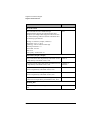
Table of Contents
Contents
1. Installing the Tape Library
Installation Overview ..................................................................... 1-2
Step 1: Choose a Location ............................................................. 1-3
Step 2: Unpack the Library ............................................................ 1-4
Required Components ................................................................. 1-4
Additional Components Provided ............................................... 1-5
Tape Library Rear Panel ............................................................. 1-6
Step 3: Install the Host SCSI Card(s) ............................................ 1-7
Step 4: Mount the Library in a Rack (optional) ............................. 1-8
Safety Precautions ....................................................................... 1-8
Tools and Components ............................................................... 1-9
Mounting the Library ................................................................ 1-10
Attach the Mounting Brackets ............................................... 1-10
Attach the Rack Slides to the Rack ........................................ 1-12
Place the Library in the Rack ................................................. 1-17
Step 5: Set the SCSI Interface Mode Switch ............................... 1-20
Step 6: Connect Library to Host .................................................. 1-23
Routing SCSI and Power Cables on Rack Mounted Libraries . 1-23
Step 7: Power On the System ...................................................... 1-27
Install Backup Software ............................................................ 1-27
Verify Installation With TapeAssure ........................................ 1-27
Moving or Shipping the Library .................................................. 1-28
2. Using Tape Cartridges
Tape Cartridge Overview ............................................................... 2-2
v
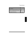
Contents
Choosing Tape Cartridges ............................................................. 2-3
Labeling Tape Cartridges ............................................................... 2-4
Labeling Bulk Load Magazines ..................................................... 2-5
Drive Cleaning Messages .............................................................. 2-6
Write-Protecting Tape Cartridges .................................................. 2-8
Maintaining Tape Cartridges ......................................................... 2-9
3. Operating the Library
Overview ........................................................................................ 3-2
Operating the Control Panel .......................................................... 3-3
Understanding Display Window Messages ................................... 3-4
Drive Status ................................................................................. 3-4
Status Indicators ....................................................................... 3-4
Activity Indicators ................................................................... 3-5
Control Panel Options ................................................................. 3-6
First Level Options .................................................................. 3-6
Second Level Options .............................................................. 3-7
Control Panel Menu Tree ............................................................ 3-8
Entering the Administration Menu Password ............................... 3-9
Setting a New Administration Menu Password ........................... 3-10
Setting and Viewing SCSI IDs .................................................... 3-11
Setting SCSI IDs ....................................................................... 3-12
Interpreting SCSI Bus Status Indicator LEDs ....................... 3-14
Viewing Current SCSI Address Settings .................................. 3-14
Loading Tape Cartridges Into the Library ................................... 3-15
vi
Table of Contents
Contents
Inserting/Removing Cartridges with Software ......................... 3-15
Keeping Cartridges in the Magazine ........................................ 3-15
Loading Tapes ........................................................................... 3-16
Removing Tape Cartridges from the Library ............................. 3-19
Viewing Cartridge Bar Code Labels ............................................ 3-22
Cleaning the Library Tape Drives ............................................... 3-23
Setting Configuration Options ..................................................... 3-25
Retrieving Performance Information ........................................... 3-28
Running an Internal Test .............................................................. 3-33
Using Online Drive Replacement ................................................ 3-37
Troubleshooting ........................................................................... 3-39
A. Supplies and Customer Support
Overview ....................................................................................... A-2
Supplies and Accessories .............................................................. A-3
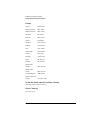
Hewlett-Packard Customer Support ............................................. A-6
HP FIRST/QUICK FAX Faxback Services .............................. A-6
Asia-Pacific ............................................................................. A-7
Europe ..................................................................................... A-8
North and South America (includes Canada) ......................... A-8
Other Countries ....................................................................... A-8
Electronic Support Services ....................................................... A-9
On-line Service Providers ....................................................... A-9
Hewlett-Packard Web Site ...................................................... A-9
Customer Support Centers ....................................................... A-10
vii
Contents
North and South America (includes Canada) ....................... A-10
European Customer Support Centers .................................... A-10
Asia-Pacific ........................................................................... A-11
Elsewhere .............................................................................. A-11
Telephone Support After Warranty ......................................... A-12
Before Calling ....................................................................... A-12
US and Canada ...................................................................... A-12
Europe ................................................................................... A-12
Elsewhere .............................................................................. A-12
HP Reseller Locator Numbers .............................................. A-12
B. Safety and Regulatory Information
Overview ........................................................................................B-2
Safety Information .........................................................................B-3
Laser Safety ................................................................................B-3
CDRH Regulations (USA Only) ................................................B-3
Regulatory Information ..................................................................B-4
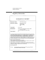
Declaration of Conformity ..........................................................B-5
United Kingdom Telecommunications Act 1984 .......................B-6
Herstellerbescheinigung ..............................................................B-6
English Translation of German Sound Emission Directive .....B-6
Turvallisuusyhteenveto ...............................................................B-7
English Translation of Finnish Regulatory Information ..........B-8
Japanese VCCI Statement ...........................................................B-9
English Translation of Japanese VCCI Statement ...................B-9
viii
Table of Contents
Contents
C. TapeAlert Messages
Overview ........................................................................................C-2
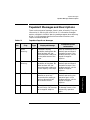
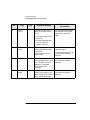
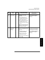
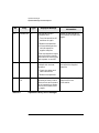
TapeAlert Messages and Descriptions ...........................................C-3
ix
Contents
x
Table of Figures
Figures
Figure 1-1. Rear Panel Features. . . . . . . . . . . . . . . . . . . . . . . . . . . . . . . 1-6
Figure 1-2. Rackmounting Components . . . . . . . . . . . . . . . . . . . . . . . . . 1-9
Figure 1-3. Rack Slides . . . . . . . . . . . . . . . . . . . . . . . . . . . . . . . . . . . . . 1-10
Figure 1-4. Front Mounting Bracket . . . . . . . . . . . . . . . . . . . . . . . . . . 1-11
Figure 1-5. Rear Mounting Bracket . . . . . . . . . . . . . . . . . . . . . . . . . . . 1-11
Figure 1-6. Clip Nuts (Front Rails). . . . . . . . . . . . . . . . . . . . . . . . . . . . 1-12
Figure 1-7. Clip Nuts (Back Rails) . . . . . . . . . . . . . . . . . . . . . . . . . . . . 1-13
Figure 1-8. Front Bracket on Rack . . . . . . . . . . . . . . . . . . . . . . . . . . . . 1-14
Figure 1-9. Rear Bracket on Rack. . . . . . . . . . . . . . . . . . . . . . . . . . . . . 1-15
Figure 1-10. Bezel Spacers . . . . . . . . . . . . . . . . . . . . . . . . . . . . . . . . . . 1-16
Figure 1-11. Strain Relief Bracket . . . . . . . . . . . . . . . . . . . . . . . . . . . . 1-17
Figure 1-12. Library on Slides . . . . . . . . . . . . . . . . . . . . . . . . . . . . . . . 1-18
Figure 1-13. Installation Handles. . . . . . . . . . . . . . . . . . . . . . . . . . . . . 1-18
Figure 1-14. Front Access Door. . . . . . . . . . . . . . . . . . . . . . . . . . . . . . . 1-19
Figure 1-15. SCSI Interface Mode Switch (Example) . . . . . . . . . . . . . 1-20
Figure 1-16. SCSI/Power Cables and Strain Relief Bracket . . . . . . . . 1-24
Figure 1-17. Front Access Door. . . . . . . . . . . . . . . . . . . . . . . . . . . . . . . 1-25
Figure 1-18. Secured SCSI and Power Cables . . . . . . . . . . . . . . . . . . . 1-26
Figure 2-1. Proper Label Position . . . . . . . . . . . . . . . . . . . . . . . . . . . . . 2-4
Figure 2-2. Magazine Label Position . . . . . . . . . . . . . . . . . . . . . . . . . . . 2-5
Figure 2-3. Write-Protect Button Settings . . . . . . . . . . . . . . . . . . . . . . . 2-8
Figure 3-1. Tape Library Control Panel . . . . . . . . . . . . . . . . . . . . . . . . . 3-3
Figure 3-2. Control Panel Menu Options . . . . . . . . . . . . . . . . . . . . . . . 3-8
xi
Figures
Figure 3-3. Opening the Front Access Door . . . . . . . . . . . . . . . . . . . . . 3-17
Figure 3-4. Loading Tape Cartridges into the Magazine . . . . . . . . . . . 3-17
Figure 3-5. Inserting Magazines . . . . . . . . . . . . . . . . . . . . . . . . . . . . . . 3-18
Figure 3-6. Opening the Front Access Door . . . . . . . . . . . . . . . . . . . . . 3-20
Figure 3-7. Removing Magazines . . . . . . . . . . . . . . . . . . . . . . . . . . . . . 3-20
xii
Table of Tables
Tables
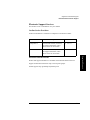
Table 1-1. Location Criteria . . . . . . . . . . . . . . . . . . . . . . . . . . . . . . . . . . 1-3
Table 1-2. Components Included for Installation . . . . . . . . . . . . . . . . . 1-4
Table 1-3. Additional Components . . . . . . . . . . . . . . . . . . . . . . . . . . . . . 1-5
Table 1-4. SCSI Interface Mode Switch Settings . . . . . . . . . . . . . . . . . 1-20
Table 1-5. Tape Library as the Only Peripheral . . . . . . . . . . . . . . . . . 1-21
Table 1-6. Tape Library with Other Peripherals . . . . . . . . . . . . . . . . . 1-22
Table 2-1. Supported Tape Types . . . . . . . . . . . . . . . . . . . . . . . . . . . . . . 2-3
Table 2-2. Drive Cleaning Messages. . . . . . . . . . . . . . . . . . . . . . . . . . . . 2-7
Table 2-3. Tape Cartridge Maintenance . . . . . . . . . . . . . . . . . . . . . . . . . 2-9
Table 3-1. Default SCSI IDs . . . . . . . . . . . . . . . . . . . . . . . . . . . . . . . . . 3-11
Table 3-2. SCSI Address Configuration Options . . . . . . . . . . . . . . . . . 3-12
Table 3-3. SCSI Status Indicators . . . . . . . . . . . . . . . . . . . . . . . . . . . . 3-14
Table 3-4. Configuration Options . . . . . . . . . . . . . . . . . . . . . . . . . . . . . 3-26
Table 3-5. Information Logs . . . . . . . . . . . . . . . . . . . . . . . . . . . . . . . . . 3-29
Table 3-6. Internal Tests . . . . . . . . . . . . . . . . . . . . . . . . . . . . . . . . . . . . 3-34
Table 3-7. Troubleshooting Table . . . . . . . . . . . . . . . . . . . . . . . . . . . . . 3-39
Table A-1. Basic Supplies and Accessories. . . . . . . . . . . . . . . . . . . . . . . A-3
Table C-1. TapeAlert Tape Error Messages . . . . . . . . . . . . . . . . . . . . . . C-3
Table C-2. TapeAlert Library Error Messages . . . . . . . . . . . . . . . . . . . . C-6
xiii
Tables
xiv
Installation
1
Installing the Tape Library
1-1
Installing the Tape Library
Installation Overview
Installation Overview
Before you install the tape library:
•
Make sure you have the components listed in Table 1-2 on page 1-4.
•
Become familiar with the back of the tape library, as shown in “Tape Library
Rear Panel” on page 1-4.
To install the library, you must:
1. Choose a location.
2. Unpack the library.
3. Install the SCSI host adapter card.
4. Mount the library in a rack (rackmount configuration only).
5. Set the SCSI interface mode switch.
6. Connect the tape library.
7. Power on the system.
NOTE
These steps are explained in this chapter. This chapter also explains how to move or
ship the library.
NOTE
After the library is installed, you must perform additional tasks explained in
Chapters 2 and 3.
1-2
Installing the Tape Library
Step 1: Choose a Location
Installation
Step 1: Choose a Location
Choose a location that meets the following criteria. Take the library there before
unpacking it.
Table 1-1
Location Criteria
Room temperature
50-104° F (10-40° C)
Power source
AC power voltage: 100-127 V or 200-240 V
Air quality
Minimal sources of particulate contamination. Avoid areas
near frequently used doors and walkways, stacks of
supplies that collect dust, and smoke-filled rooms.
CAUTION: Excessive dust and debris can damage tapes
and tape drives.
Adequate
clearance
Standalone configuration — free standing or against a
wall/desk:
Back
56 cm (22 in.) for cooling and service.
Front
86 cm (34 in.) for operator access.
Sides
56 cm (22 in.) for removal of the external
cover.
If less space is allowed, move the library to an open area
before servicing.
Rack mount configuration:
Back
Allow adequate room to open the rear door of
the rack for service access, usually 46-61 cm
(18-24 in.), depending on the rack.
Front
86 cm (34 in.) for operator access.
Height
For ease of use, install the library so the
bottom is 60-120 cm (24-48 in.) above the
floor. Do not install the library in the bottom
rail position because of clearance.
1-3
Installing the Tape Library
Step 2: Unpack the Library
Step 2: Unpack the Library
Make sure you have all required components and become familiar with the library’s
components.
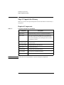
Required Components
Table 1-2
Components Included for Installation
Component
NOTE
Description
Tape Library
Unpack the library when it is in the desired location.
SCSI card(s)
One single-ended FAST/WIDE SCSI is included with
the library. Data is transferred up to 20 Mbytes/second.
For FAST handshaking, the total length of the SCSI bus
is limited to 3 meters.
SCSI cable:
allowable lengths
One 3-meter single-ended FAST/WIDE SCSI is included
with the library.
Daisy-chain cable
Included with two-drive libraries.
Power cord
Included with library.
Rackmount kit
Included with rackmount libraries.
Data cartridge
Five tapes are included with library.
Cleaning cartridge
One cleaning tape is included with library.
Contact your service representative if you are missing any components.
1-4
Installing the Tape Library
Step 2: Unpack the Library
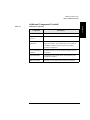
Additional Components Provided
Installation
Table 1-3
Additional Components
Component
Description
User’s Guide
Printed user’s manual in English.
DLT Library
Advisor
Online user’s manual with video clips.
HP SureStore Tape
CD-ROM
Includes TapeAssure/TapeAlert, as well as other
diagnostic utilities. Also includes the User’s Guide on
CD-ROM, translated into French, Italian, German,
Spanish, and Japanese.
Live Trial Backup
Software
Includes live trial versions of backup software for your
evaluation.
Tape Data Sheet
Describes the tape specifications, characteristics, and
maintenance needed
Bar Code Labels
Includes bar code labels and reordering information.
1-5
Installing the Tape Library
Step 2: Unpack the Library
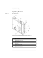
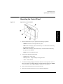
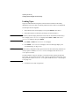
Tape Library Rear Panel
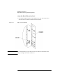
Figure 1-1
Rear Panel Features
The following list identifies the numbered components in Figure 1-1:
1
Bus 1 SCSI ports
2
SCSI interface mode switch
3
Bus 2 SCSI ports
4
Power port
5
SCSI bus indicator label
6
SCSI bus status indicators
1-6
Installing the Tape Library
Step 3: Install the Host SCSI Card(s)
Installation
Step 3: Install the Host SCSI Card(s)
Install the single-ended or differential SCSI card into the host computer system.
Refer to the host user manual and the SCSI card installation instructions for
information on installing and configuring SCSI cards.
1-7
Installing the Tape Library
Step 4: Mount the Library in a Rack (optional)
Step 4: Mount the Library in a Rack (optional)
For stand-alone installations, go to “Step 5: Set the SCSI Interface Mode Switch” on
page 1-20.
The rack slides can be adjusted to fit any standard rack with a depth of 26 to 31
inches (66.04 to 78.75 centimeters).
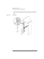
Safety Precautions
Because the tape library weighs approximately 100 pounds (45 kilograms), the
following safety precautions must be taken when mounting the tape library:
WARNING
•
Fully extend the rack’s antitip rail and lower the leveller feet.
•
Mount the tape library no higher than 4 feet (122 centimeters) in the rack.
•
IMPORTANT: At least two people must lift the library during installation.
Do not pull the library out of the rack to its fully extended position unless the
anti-tip rail on the bottom of the rack has been positioned correctly. Do not
attempt to move the tape library by yourself.
The tape library weighs approximately 100 pounds (45 kilograms). Pulling the
library out of the rack without the rack’s anti-tip rail extended could result in
personal injury and/or damage to the tape library if the rack tips over.
1-8
Installing the Tape Library
Step 4: Mount the Library in a Rack (optional)
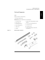
Tools and Components
Installation
Tools:
Phillips screwdriver (included in kit)
1/2 inch open-ended wrench
Kit Hardware (parts are labeled for easy identification):
1. rack slides (1 pair)
2. bezel spacers (2)
3. mounting brackets (4)
4. strain relief bracket (1)
5. cable ties (4)
6. template
Figure 1-2
7. 8-32 x 3/8 pan slotted phillips lw profile
hd (14)
8. 10-32 x 5/8 pan slotted phillips (14)
9. 10-32 clip nuts (12)
10. 8-32 keps nuts (8)
11. 6-32 x 3/8 pan phillips, with internal
lockwasher (1)
Rackmounting Components
1-9
Installing the Tape Library
Step 4: Mount the Library in a Rack (optional)
Mounting the Library
To mount the tape library in a rack, you must:
•
First, attach the front and back mounting brackets to the rack slides.
•
Next, attach the rack slides to the rack.
•
Finally, attach the tape library to the rack slides.
These steps are explained in detail in the following sections.
Attach the Mounting Brackets
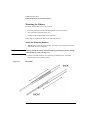
1. IMPORTANT: Lower the rack’s leveller feet using a 1/2-inch open-end wrench,
and extend the rack’s antitip rail.
WARNING
Failure to extend the antitip rail could result in personal injury and/or damage
to the tape library if the rack tips over.
2. Pull the rack slide members out to the fully extended position. (The slides
should “click” into a locked position.)
Figure 1-3
Rack Slides
1-10
Installing the Tape Library
Step 4: Mount the Library in a Rack (optional)
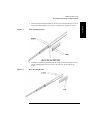
Figure 1-4
Front Mounting Bracket
4. Attach the rear mounting brackets to the back side of each slide using two 8-32 x
3/8 pan-slotted phillips screws and two 8-32 keps nuts. Do not tighten the
screws.
Figure 1-5
Rear Mounting Bracket
1-11
Installation
3. Attach the front mounting brackets to the front end of each slide using two 8-32
x 3/8 pan-slotted phillips screws and two 8-32 keps nuts. Tighten the screws.
Installing the Tape Library
Step 4: Mount the Library in a Rack (optional)
Attach the Rack Slides to the Rack
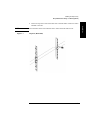
1. Line up the template with an existing product in the rack. Attach clip nuts to
each front rail in the locations indicated on the template.
Figure 1-6
NOTE
Clip Nuts (Front Rails)
Do not install the library in the bottom of the rack. Make sure the bottom of the
library is no higher than 4 feet off the floor.
1-12
Installing the Tape Library
Step 4: Mount the Library in a Rack (optional)
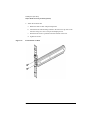
NOTE
Figure 1-7
Count the holes on the front and back rails to ensure the slides will be level.
Clip Nuts (Back Rails)
1-13
Installation
2. Attach two clip nuts to each of the back rails so that the slides will be level when
attached to the rails.
Installing the Tape Library
Step 4: Mount the Library in a Rack (optional)
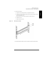
3. Attach the front bracket:
a. Return the slides to their compressed position.
b. Attach the front slide mounting bracket to the lower two clip nuts on the
front rails using two 10-32 x 5/8 pan slotted phlp screws.
c. Push the slides as far as possible toward the outside of the rack.
d. Tighten the screws.
Figure 1-8
Front Bracket on Rack
1-14
Installing the Tape Library
Step 4: Mount the Library in a Rack (optional)
4. Attach the rear bracket:
b. Attach the rear slide mounting bracket to the rear clip nuts using two 10-32 x
5/8 pan slotted phlp screws.
c. Push the slides as far as possible toward the outside of the rack.
d. Tighten the screws.
e. Tighten all bracket screws.
Figure 1-9
Rear Bracket on Rack
5. Extend the slides fully, make sure they are parallel, and then recompress them.
1-15
Installation
a. Adjust the rear mounting brackets to fit lengthwise in the rack.
Installing the Tape Library
Step 4: Mount the Library in a Rack (optional)
6. Connect the two bezel spacers to the front rails using two 10-32 x 5/8 pan slotted
phlp screws. The screws attach to the two clip nuts on the front rails above the
slides.
Figure 1-10
Bezel Spacers
1-16
Installing the Tape Library
Step 4: Mount the Library in a Rack (optional)
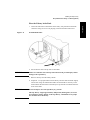
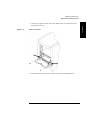
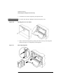
Place the Library in the Rack
Figure 1-11
Strain Relief Bracket
2. Ensure that the rack’s anti-tip rails are extended.
WARNING
Failure to extend the rack’s anti-tip rail could result in personal injury and/or
damage to the tape library.
3. Remove the keys from the library handle.
4. Important – two people needed: Lift the library onto the slides and back slightly
into the rack using the side handles. Make sure the handles sit securely on the
slides and that the front holes in the library line up with the second hole from the
front on the slides.
WARNING
Do not attempt to move the tape library by yourself.
The tape library weighs approximately 100 pounds (45 kilograms). To avoid
personal injury and/or damage to the tape library, a minimum of two people
are needed to move the library.
1-17
Installation
1. Attach the cable strain relief bracket to the library rear panel below the SCSI
connectors using one 6-32 x 3/8 pan phlp, with internal lockwasher screw.
Installing the Tape Library
Step 4: Mount the Library in a Rack (optional)
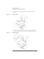
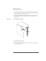
5. Attach the library to each slide using three 8-32 x 3/8 pan-slotted phillips
screws.
Figure 1-12
Library on Slides
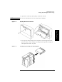
6. Remove the installation handles by removing two screws on each handle. Keep
the screws and handles in case the library needs to be reshipped in the future.
Figure 1-13
Installation Handles
1-18
Installing the Tape Library
Step 4: Mount the Library in a Rack (optional)
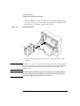
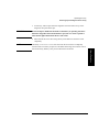
7. Release the slide latch springs, then push the tape library into the rack.
Figure 1-14
Front Access Door
1-19
Installation
8. Open the front access door using the key, and secure the library to the rack
through the rectangular holes in the door using two 10-32 x 5/8 pan slotted phlp
screws.
Installing the Tape Library
Step 5: Set the SCSI Interface Mode Switch
Step 5: Set the SCSI Interface Mode Switch
Do not connect any cables yet.
The SCSI interface mode switch, shown below, is on the rear panel between the bus
1 and bus 2 SCSI ports.
Figure 1-15
SCSI Interface Mode Switch (Example)
To set the SCSI interface mode switch:
1. Determine how to connect the library according to:
NOTE
•
Number of drives in the library and drive type
•
Other peripherals (if any) on your system
•
Type of SCSI card (differential or single-ended)
For best library performance, connect only one library on a SCSI bus.
2. Set the SCSI interface mode switch.
Table 1-4
SCSI Interface Mode Switch Settings
Setting
Purpose
Set to
Term Pwr
Sends power to the terminator.
ON in most installations
Termination
Terminates the SCSI bus. Functions the
same as a physical terminator.
ON if the tape drive is the last device
on the SCSI chain
OFF if another peripheral will connect
to the library
DIFF/SE
Specifies whether you are using the
differential or single-ended port.
1-20
DIFF for differential
SE for single-ended
Installing the Tape Library
Step 5: Set the SCSI Interface Mode Switch
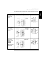
The following table shows connection options when there are no other peripherals.
Configuration
One-Drive Tape
Library
Two-Drive Library:
Daisy chained
Minimum host I/O
slots used
Tape Library as the Only Peripheral
Cabling
Mode Switch Settings
Single-ended SCSI
connection
Single-ended
SCSI connection
shown
Two-Drive Library
Bus 1 and bus 2
connect to separate
SCSI cards
Maximum
performance
Differential SCSI
connection shown
Additional card and
cable required
1-21
Installation
Table 1-5
Installing the Tape Library
Step 5: Set the SCSI Interface Mode Switch
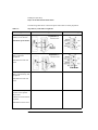
The following table shows connection options when there are other peripherals.
Table 1-6
Tape Library with Other Peripherals
Configuration
Cabling
One-Drive Tape Library:
Library on its own bus
Mode Switch Settings
Single-ended SCSI
connection shown
Maximum performance
bus 2 not used
One-Drive Tape Library:
Daisy chained to
peripheral
Single-ended SCSI
connection shown
Minimum host I/O slots
used
EXVQRWXVHG
Two-Drive Library:
Daisy chained library and
peripheral
Minimum host I/O slots
used
Two-Drive Library: bus 1
and bus 2 use separate
SCSI cards
Additional card and cable
required
Minimum I/O slots used
1-22
Installing the Tape Library
Step 6: Connect Library to Host
Installation
Step 6: Connect Library to Host
Do not turn on the host system or library yet!
1. Properly shut down all peripheral devices connected to the host computer.
If the host computer is connected to a network, be sure to check with the system
administrator before switching off power.
2. Switch off power to the server.
3. Connect the SCSI cables.
Before you set the mode switch, you determined how to configure your SCSI
bus (see the connection diagrams on page 1-21 and page 1-22). Using this
configuration, connect the library to the host. Make sure:
•
You use the proper port (single-ended or differential).
•
The last device in the SCSI bus is terminated.
4. Make sure the power switch on the library front panel is switched off.
5. Plug the power cord into the power port on the back of the library.
Stand-alone installations: Go to “Step 7: Power On the System” on page 1-27.
Rack mount installations: Go to the next section, “Routing SCSI and Power Cables
on Rack Mounted Libraries.”
Routing SCSI and Power Cables on Rack Mounted
Libraries
CAUTION
SCSI and power cables must be routed and secured properly on rack mounted
libraries. Failure to properly route library cables could result in damage to the
cables.
To properly route and secure rack mounted library power and SCSI cables:
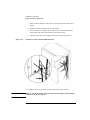
1. Route the SCSI/power cables through the strain relief bracket:
a. Squeeze the two plastic ends of the cable strain relief bracket together.
b. Pull off the plastic strain relief clamp.
1-23
Installing the Tape Library
Step 6: Connect Library to Host
c. Route the SCSI cable(s) and the power cord through the cable strain relief
bracket.
d. Slide the strain relief clamp back onto the bracket.
e. Attach a cable tie (included in the rack mount kit) to the SCSI and power
cables about eight inches back from the strain relief bracket.
f. Attach another cable tie about eight inches back from the first cable tie.
Figure 1-16
SCSI/Power Cables and Strain Relief Bracket
2. Extend the rack’s anti-tip rail and verify that the leveller feet are down.
WARNING
Failure to extend the antitip rail could result in personal injury and/or damage
to the library if the rack tips over.
1-24
Installing the Tape Library
Step 6: Connect Library to Host
Figure 1-17
Front Access Door
4. Slide the library out of the rack so that it is in the fully extended position.
1-25
Installation
3. Use the key to open the front access door. Remove the two screws that secure
the library to the rack.
Installing the Tape Library
Step 6: Connect Library to Host
5. Gently pull the SCSI and power cables back toward the rear of the rack. Use a
cable tie to secure them to the rail at the back of the rack. The cable tie should be
at about the same height as the top of the library.
6. Carefully route the cables down along the back rail. Use a cable tie to secure
them to the rail just above the slide mounting bracket. Clip off the ends of all
four cable ties.
Figure 1-18
Secured SCSI and Power Cables
7. Close the back door on the rack.
8. Push the library back into the rack.
9. Open the front access door. Replace the two screws that secure the library to the
rack, then re-lock the door.
1-26
Installing the Tape Library
Step 7: Power On the System
Installation
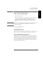
Step 7: Power On the System
1. Plug the power cord into a grounded outlet.
2. Turn on the power switch.
Initially SELF TEST and NOT READY, and then NOT READY and INVENTORY
CHECK alternately appear in the display window on the library. After the
power-on test completes (approximately 1.5 minutes), the drive status
information displays. (See “Understanding Display Window Messages” on
page 3-4.)
NOTE
If the drive status information does not display, the power-on test was not successful
and DEVICE FAILED displays. See “Troubleshooting” on page 3-38 for
troubleshooting procedures.
3. Turn on other peripherals (if any).
4. Turn on the host system.
Install Backup Software
Follow the instructions provided with your backup software to configure it to your
library. Several trial versions are provided with the library for your evaluation.
Verify Installation With TapeAssure
HP TapeAssure is a software utility that tells you quickly and easily whether your
configuration is correct and whether the tape drive is ready for use with backup
software. Your backup software must be TapeAlert compatible for you to receive
these messages (compatible packages will display the HP TapeAlert logo). For the
latest list of backup packages that support TapeAlert, refer to HP’s World Wide
Web site (http://www.hp.com/go/tape).
1-27
Installing the Tape Library
Moving or Shipping the Library
Moving or Shipping the Library
This section explains how to move the library a short distance, such as to another
office or to another floor in the building and how to ship the library to another
location.
WARNING
The library weighs approximately 100 pounds (45 kilograms). To avoid
personal injury and possible damage to the library, at least two people must
move the library.
To move or ship the library:
1. Properly shut down and power off the host.
2. Unmount (unreserve) any tape cartridges in the library if necessary. See your
computer operating system documentation, or software application
documentation for instructions on how to unmount tape cartridges.
3. Verify that all drives in the library are empty:
If the drives are full, empty them before shipping the library. (For instructions,
refer to the software documentation your host system uses to manage the
library.)
4. Switch off the power switch on the library front panel.
CAUTION
Do not switch off power to the library until the SCSI bus is inactive.
Removing power from a SCSI peripheral when the bus is active can result in data
loss and/or indeterminate bus states. (Check your host system manuals for
information about checking the SCSI bus status.) If your computer is connected to a
LAN, be sure to check with your system administrator before shutting off power to
the library.
5. Remove the power cord and the SCSI cable connections from the library rear
panel.
1-28
Installing the Tape Library
Moving or Shipping the Library
6. If the library is rack mounted:
WARNING
Extend the anti-tip rail on the rack.
Failure to extend the anti-tip rail could result in personal injury and/or damage
to the library if the rack tips over.
b. Slide the library out of the rack so that it is in the fully extended position.
c. Reattach the handles to the side of library using two screws. Make sure the
handle flanges are on top of the slides. (The handles and hardware for
reattaching them should have been saved with the original shipping
materials. If they are missing, call your service representative to order
replacement handles.)
d. Remove the three 8-32 screws on each side of the library that secure the
library to the rack slides.
e. IMPORTANT — two people needed: With a person on each side of the
library, lift the library onto a cart.
7. Transport the library:
CAUTION
•
To move the library a short distance, roll the cart to the new location.
•
To ship the library, repackage the library in the same materials and ship it in
the same manner in which it was received.
The library can be seriously damaged if it is not shipped using appropriate shipping
materials. A service representative can provide assistance or advice on how to best
repackage and ship the library.
8. Re-install the library. Refer to installation steps in this chapter.
1-29
Installation
a.
Installing the Tape Library
Moving or Shipping the Library
1-30
Using Tapes
2
Using Tape Cartridges
2-1
Using Tape Cartridges
Tape Cartridge Overview
Tape Cartridge Overview
The tape cartridges you use in the tape drive are an integral part of the storage
process. This chapter explains how to:
NOTE
•
Choose a tape cartridge.
•
Label tape cartridges with bar code labels.
•
Label bulk load magazines.
•
Interpret drive cleaning messages.
•
Write-protect a tape cartridge.
•
Maintain a tape cartridge.
For top performance and reliability, Hewlett Packard recommends HP-labeled tape
cartridges that have been fully tested for use with HP’s tape products. Purchase
these cartridges through any HP-authorized dealer, or order them through HP
Direct. See “Supplies and Accessories” on page A-3 for ordering information.
2-2
Using Tape Cartridges
Choosing Tape Cartridges
Choosing Tape Cartridges
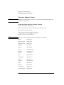
Two types of compatible digital linear tape cartridges are available:
Table 2-1
Supported Tape Types
HP DLTtape IV Data Cartridge
Using Tapes
Cartridge Type
Available Densities
20 GBytes uncompressed
(DLT4000 drive)
35 GBytes uncompressed
(DLT7000 drive)
HP DLTtape III XT Data Cartridge
NOTE
15 GBytes uncompressed
Hewlett-Packard recommends using the HP DLTtape IV Data Cartridge for top
performance, highest capacity, and least amount of head cleaning.
Using Tape Cartridges
2-3
Using Tape Cartridges
Labeling Tape Cartridges
Labeling Tape Cartridges
Make it a practice to use bar code labels on your tape cartridges. Your host software
may need to keep track of the following information and the associated bar code:
•
date of format or initialization
•
cartridge owner (such as group or department)
•
storage purpose (such as backup, old version of operating system)
If the host software does not keep track of this information, create a method of doing
so.
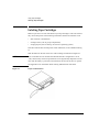
Slide the label into the slot on the face of the cartridge as illustrated in Figure 2-1.
NOTE
If bar code labels are not used and the “Barcode On/Off” configuration is set to
“Off,” the Inventory Check test performance can be significantly impacted. This test
runs when the library is powered on and whenever the front access door is opened.
See Appendix A for information about ordering additional bar code labels.
Figure 2-1
Proper Label Position
2-4
Using Tape Cartridges
Labeling Bulk Load Magazines
Labeling Bulk Load Magazines
Bulk load magazines can be labeled in a manner similar to tape cartridges.
To label bulk load magazines:
Using Tapes
1. Clean the magazine surface with isopropyl alcohol (optional, but
recommended).
2. Remove the adhesive backing from the label pouch.
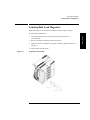
3. Apply the pouch to the magazine anywhere within the shaded area shown in
Figure 2-2.
4. Slide the label into the pouch.
Figure 2-2
Magazine Label Position
Using Tape Cartridges
2-5
Using Tape Cartridges
Drive Cleaning Messages
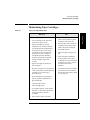
Drive Cleaning Messages
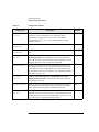
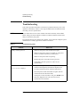
Table 2-2 lists drive cleaning messages that might be caused by a tape. Note that:
NOTE
•
The tape drives do not require scheduled cleaning maintenance. Excessive use of
the cleaning cartridge can cause unnecessary wear on the drive head.
•
After 20 cleaning cycles, the cleaning cartridge must be replaced.
For drive cleaning instructions, refer to “Cleaning the Library Tape Drives” on
page 3-23.
2-6
Using Tape Cartridges
Drive Cleaning Messages
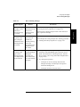
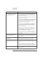
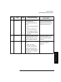
Table 2-2
Drive Cleaning Messages
You need to:
A brand new tape
cartridge is used
and a drive
cleaning message
is received.
Debris from the
tape manufacturing
process was
deposited on the
drive head.
Clean the drive using the tape library cleaning procedure in
“Cleaning the Library Tape Drives” on page 3-23.
An older,
frequently used
tape cartridge is
loaded and a drive
cleaning message
is received.
Dust from frequent
tape loads and
unloads has
probably built up
on the tape
cartridge and was
deposited on the
drive head.
Clean the outside of the tape cartridge with a damp cloth.
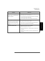
An older,
frequently used
tape causes a
cleaning message
to be displayed for
the second time.
The tape is
probably damaged.
(Damaged
cartridges can
cause unnecessary
use of the cleaning
cartridge.)
1. Verify the tape is readable by clearing the error message.
(Select the ONLINE REPAIR option from the control
panel. Turn off the drive containing the tape. Turn the
drive on again. (See “Using Online Drive Replacement”
on page 3-36).
If the message is displayed again within a short amount of
time, replace the cartridge.
Clean the tape drive using the tape drive cleaning procedure
in “Cleaning the Library Tape Drives” on page 3-23.
2. Try reading the tape again:
•
If the tape can be read, back up data from the
damaged cartridge to another tape cartridge and
discard the damaged one.
•
If the tape cannot be read, call service.
2-7
Using Tape Cartridges
Reason:
Using Tapes
If this happens:
Using Tape Cartridges
Write-Protecting Tape Cartridges
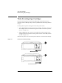
Write-Protecting Tape Cartridges
The use of the write protect switch ensures data safety for files that have been
previously written to the tape and prevents any additional files from being written to
the tape.
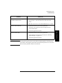
To change the write-protect setting, move the write-protect switch:
•
Left to prevent data from being written to the cartridge. The orange indicator on
the cartridge can be seen when the write-protect switch is in the “ON” position
(see “A” in Figure 2-3).
•
Right to allow data to be written to the cartridge. The orange indicator on the
cartridge cannot be seen when the write-protect switch is in the “OFF” position
(see “B” in Figure 2-3).
With the write-protect switch in either position, data can be read from the cartridge.
Figure 2-3
Write-Protect Button Settings
Write-Protected
Not Write-Protected
2-8
Using Tape Cartridges
Maintaining Tape Cartridges
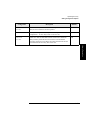
Maintaining Tape Cartridges
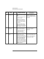
Table 2-3
Tape Cartridge Maintenance
DO NOT:
•
Leave cartridges in the tape drive
when library power is off.
•
Expose cartridges to extreme
temperatures or extreme humidity.
Acceptable operating temperatures
range from 10-40° C (50-104° F).
Acceptable storage temperatures
range from 16-32° C (60-90° F).
Acceptable operating humidity
ranges from 20-80%; acceptable
storage humidity ranges from
10-95%.
•
Expose cartridges to moisture or
direct sunlight.
•
Drop the cartridges or carry them in a
loose container that could submit the
cartridges to any unnecessary
physical shock.
•
Open cartridges lid, exposing the
tape to possible contamination or
physical damage.
•
Touch the tape surface.
•
Take cartridges apart.
•
Use graphite pencils, water soluble
felt pens, or other debris-producing
writing instruments to label
cartridges.
•
Erase a label; replace it instead.
•
Store cartridges in a clean, safe
place in their protective plastic
containers when not in use.
•
Remove dust on the outside of
cartridges using a damp cloth.
(Older, frequently used tapes
may build up dust.)
•
Store cartridges vertically, not
flat.
•
Store cartridges intended for
archiving data in their plastic
containers and in environmental
conditions of 18-28° C (64-82°
F) and 40-60% relative
humidity.
•
Use labels like those included in
the accessories kit or that meet
the specifications listed in Table
A-1 on page A-3.
2-9
Using Tape Cartridges
Expose cartridges to magnetic fields.
Using Tapes
•
DO:
Using Tape Cartridges
Maintaining Tape Cartridges
2-10
Library Operation
3
Operating the Library
3-1
Operating the Library
Overview
Overview
This chapter explains the following library operations:
•
“Operating the Control Panel” on page 3-3
•
“Understanding Display Window Messages” on page 3-4
•
“Entering the Administration Menu Password” on page 3-9
•
“Setting a New Administration Menu Password” on page 3-10
•
“Setting and Viewing SCSI IDs” on page 3-11
•
“Loading Tape Cartridges Into the Library” on page 3-15
•
“Removing Tape Cartridges from the Library” on page 3-19
•
“Viewing Cartridge Bar Code Labels” on page 3-22
•
“Cleaning the Library Tape Drives” on page 3-23
•
“Using Online Drive Replacement” on page 3-36
•
“Setting Configuration Options” on page 3-25
•
“Retrieving Performance Information” on page 3-28
•
“Running an Internal Test” on page 3-32
•
“Using Online Drive Replacement” on page 3-36
•
“Troubleshooting” on page 3-38
3-2
Operating the Library
Operating the Control Panel
Operating the Control Panel
Figure 3-1
Tape Library Control Panel
Library Operation
1. Selection buttons allows you to perform the following operations:
•
CANCEL
•
PREV
•
NEXT
•
ENTER
cancels the current operation or option.
scrolls the display options backward by one. When held continuously,
the options scroll quickly.
scrolls the display options forward by one. When held continuously,
the options scroll quickly.
selects the displayed option.
2. Activity light indicates the following:
•
Steady Green – power is on.
•
Flashing Green – a tape cartridge is being accessed.
•
Amber – fault indicator.
3. 16-Character Display displays information about the current operation or drive
status. An asterisk (*) indicates there is a menu beneath the option. Press ENTER
to access the menu. Press NEXT or PREV to display the menu options.
4. Power switch switches power to the unit on and off.
5. Door latch locks/unlocks door for access to bulk load magazines.
3-3
Operating the Library
Understanding Display Window Messages
Understanding Display Window Messages
The display window displays drive status indicators and menu options.
Drive Status
The following figure shows the drive status indicators displayed when the library is
in the “ready” state.
In this example:
1. Drive 1 has a cartridge inserted and data is being written to the tape.
2. Drive 2 has a write-protected cartridge inserted.
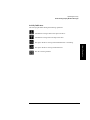
Status Indicators
Status indicators provide drive status information for the drive number that precedes
one of the following indicators.
The drive is full.
The drive is empty.
The drive needs to be cleaned.
The tape cartridge in the drive is write-protected.
3-4
Operating the Library
Understanding Display Window Messages
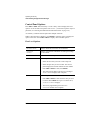
Activity Indicators
The activity light flashes during the following operations:
Information is being written to the tape in the drive.
Information is being read to the tape in the drive.
The tape in the drive is being searched backward or is rewinding.
Library Operation
The tape in the drive is being seached forward.
The drive is being cleaned.
3-5
Operating the Library
Understanding Display Window Messages
Control Panel Options
Press PREV or NEXT while the library is in the “ready” state to display first-level
options. Access second-level options from ADMIN * (second level options require a
password; see “Entering the Administration Menu Password” on page 3-9).
An asterisk (*) indicates that the option has multiple selections.
When a menu selection is flashing, press ENTER to select the option or display the
option’s selections. Press PREV or NEXT to display other available options.
First Level Options
RELEASE DOOR
Select to allow the access door to be unlocked.
VIEW BAR
CODES *
Select to view the bar code labels on each tape cartridge
by slot number.
ADMIN *
Accesses second-level options.
LOAD DRIVE *
Loads a tape from a slot to the drive. To load a tape:
1. Select the drive that you want to load a tape into.
2. Select the tape that you want to load. The control
panel displays the barcode number and slot number.
Press PREV or NEXT to select, then ENTER.
3. The control panel displays the drive it is loading to.
TAPE LOADED displays when complete.
UNLOAD DRIVE *
Unloads a tape from the drive to the slot it came from.
1. Press PREV or NEXT to select the drive that you want
to unload. Press ENTER. If a tape is not in the drive,
SOURCE IS EMPTY displays.
2. The activity light flashes green and TAPE
UNLOADED flashes when complete.
3-6
Operating the Library
Understanding Display Window Messages
Second Level Options
Displays performance information stored in the library.
TEST *
Runs internal library tests.
CONFIG *
Customizes the way the library functions.
CLEAN DRIVES *
Displays the drive numbers you wish to clean.
OVERRIDE DOOR *
Opens the door when media is in drives.
SCSI IDs *
Sets the SCSI addresses for the robotics and the library
drives.
ONLINE REPAIR *
De-activates a drive for replacement.
3-7
Library Operation
INFO *
Operating the Library
Understanding Display Window Messages
Control Panel Menu Tree
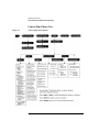
Figure 3-2
Control Panel Menu Options
3-8
Operating the Library
Entering the Administration Menu Password
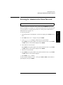
Entering the Administration Menu Password
1 2 → ADMIN * → CONFIG *
A numeric password is required to access options beneath ADMIN* menu of the
library (see Figure 3-2 on page 3-8). A three-part default password of 000-000-000
is set at the factory. To change the password, see “Setting a New Administration
Menu Password” on page 3-10.
1. Verify that the drive status displays. If it does not display, press CANCEL until it
does.
2. Press NEXT until ADMIN * displays, then press ENTER.
3. PSWD 000-000-000 displays, and the first set of zeros flashes.
Press ENTER to accept this number (if no password has been set), or press NEXT
or PREV until the correct number displays. Press ENTER.
4. The middle set of zeros flashes.
Press ENTER to accept this number (if no password has been set), or press NEXT
or PREV until the correct number displays. Press ENTER.
5. The last set of zeros flashes.
6. Press ENTER to accept this number (if no password has been set), or press NEXT
or PREV until the correct number displays.
7. Press ENTER. INFO * displays.
To access options under the ADMIN * menu, press PREV or NEXT until the desired
option displays, then press ENTER.
3-9
Library Operation
To enter the password:
Operating the Library
Setting a New Administration Menu Password
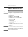
Setting a New Administration Menu Password
1 2 → ADMIN * → CONFIG * NEW PASSWORD
NOTE
Change the password to so that only authorized persons can access the library and
change operation settings. Do not forget the password. Only a service representative
can reset the password to the factory setting.
To set a new password:
1. Follow the steps on “Entering the Administration Menu Password” on page 3-9
to enter the existing password.
2. Press NEXT until CONFIG * displays, then press ENTER.
3. Press NEXT or PREV until NEW PASSWORD displays, then press ENTER.
4. NEW 000-000-000 displays, and the first set of zeros flashes.
Press NEXT or PREV to display the new numbers you wish to assign the first part
of the password, then press ENTER.
5. The second set of zeros flashes.
Press NEXT or PREV to display the new numbers you wish to assign the second
part of the password, then press ENTER.
6. The last set of zeros flashes.
Press NEXT or PREV to display the new numbers you wish to assign the third part
of the password, then press ENTER.
7. PASSWORD CHANGED displays. Press CANCEL three times to return to the drive
status (“ready” state).
NOTE
Save the new password to flash ROM by power cycling the library, which allows the
password to be recovered if the library is powered off for more than ten days.
Do not switch off power to the library until the SCSI bus is inactive. Removing
power from a SCSI peripheral when the bus is active can result in data loss and/or
indeterminate bus states. If the library is connected to a LAN, check with the system
administrator before shutting off power to the library.
3-10
Operating the Library
Setting and Viewing SCSI IDs
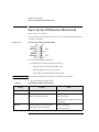
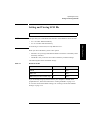
Setting and Viewing SCSI IDs
1 2 → ADMIN * → SCSI IDs *
NOTE
The tape library has a Fast/Wide SCSI interface. SCSI addresses can be set from:
0 to 7 on a DLT 4000-based library
•
0 to 15 on a DLT 7000-based library
If connecting to a narrow host, use only addresses 0 to 7.
When you choose SCSI IDs, you have two options:
•
SET IDs * lets you assign individual SCSI IDs to each drive in the library and to
the library controller.
•
VIEW IDs * lets you see the current drive and library controller settings.
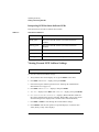
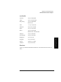
The following table shows the default settings:
Table 3-1
Default SCSI IDs
DEVICE
SCSI ID
BUS #
LIB ID
6
Bus 1
DRV 1 ID
5
Bus 1
DRV 2 ID (two-drive models only)
4
Bus 2
If you are already using any of these IDs for your computer or another SCSI
peripheral device, follow the instructions in “Setting SCSI IDs” on page 3-12.
To view the current SCSI address settings, see “Viewing Current SCSI Address
Settings” on page 3-14.
3-11
Library Operation
•
Operating the Library
Setting and Viewing SCSI IDs
Setting SCSI IDs
1 2 → ADMIN * → SCSI IDs * → SET IDs *
A SCSI ID is required for the robotics controller and each drive. The default IDs are
shown in Table 3-1 on page 3-11.
The following configuration choices are available:
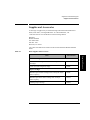
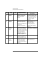
Table 3-2
SCSI Address Configuration Options
Number of
Drives
SCSI Bus Addresses Available
1
13 addresses are available on bus 1. (Drive 1 uses one address
and the library controller uses 1 address.)
2
If buses 1 and 2 are connected to separate host SCSI cards:
•
13 addresses are available on bus 1 for other devices.
•
14 addresses are available on bus 2 for other devices.
If buses 1 and 2 are daisy-chained:
•
12 addresses are available on the bus for other devices.
To change the current SCSI address settings:
1. Verify that the drive status displays (if not, press CANCEL until it does).
2. Press NEXT until ADMIN * displays, then press ENTER.
3. Enter the three-part numerical password (see “Entering the Administration
Menu Password” on page 3-9).
4. Press NEXT until SCSI IDs * displays, then press ENTER.
5. SET IDs * displays. Press ENTER.
LIB BUS # ID # or DRV # BUS # ID # displays. LIB BUS # ID # stands for the
current SCSI ID of the robotics controller. DRV # BUS # ID # is the current
SCSI ID setting for the drive number and its associated bus #.
6. Press NEXT until the setting to change displays, then press ENTER.
3-12
Operating the Library
Setting and Viewing SCSI IDs
7. The current SCSI address setting flashes. Press NEXT or PREV until the desired
address displays, then press ENTER.
8. Press NEXT until UPDATE IDs NOW displays, then press ENTER.
9. IDs SAVED displays briefly, then one of the following messages displays:
•
If the new settings do not conflict with other SCSI IDs in the library,
SCSI IDs * displays.
•
If the new settings conflict with other IDs in the library, CONFLICT
ABORTED displays briefly, then SET IDs * displays. Any changes entered
are lost, and previous steps must be repeated to set a new address.
•
If a serial communications error is detected while trying to set the SCSI IDs,
DRV CONNECT ERR displays, followed by IDs NOT CHANGED. Any
changes entered are lost. The SCSI IDs* menu displays.
10. Press CANCEL three times to return to the drive status (“ready” state).
NOTE
To save new settings can be saved to flash ROM, turn the library off, then turn it
back on. This allows the settings to be recovered if the library is powered off for
more than ten days.
Do not switch off power to the library until the SCSI bus is inactive. Removing
power from a SCSI peripheral when the bus is active can result in data loss and/or
indeterminate bus states. (Check the host system manuals for information about
checking the SCSI bus status.) If the host is connected to a LAN, be sure to check
with the system administrator before shutting off power to the library.
3-13
Library Operation
If any buses are daisy chained together, make sure the SCSI IDs are different
for each device on the bus.
Operating the Library
Setting and Viewing SCSI IDs
Interpreting SCSI Bus Status Indicator LEDs
Each SCSI bus has an LED to indicate the bus status.
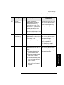
Table 3-3
SCSI Status Indicators
Indication
Status
Steady green
Port active and OK. Internal (on-board) termination
enabled.
Flashing green
Port active and OK. Internal (on-board) termination
disabled.
No light
Port not active or not configured.
Flashing red
Bus mismatch or loss of external termination power.
Flashing yellow
Bus off-line for on-line drive replacement.
Viewing Current SCSI Address Settings
1 2 → ADMIN * → SCSI IDs * → VIEW IDs *
To view the current SCSI address settings:
1. Verify that the drive status displays. If not, press CANCEL until it does.
2. Press NEXT until ADMIN * displays, then press ENTER.
3. Enter the three-part numerical password (see “Entering the Administration
Menu Password” on page 3-9).
4. Press NEXT until SCSI IDs * displays, then press ENTER.
5. SET IDS * displays. Press NEXT until VIEW IDS * displays, then press ENTER.
6. BUS # LIB ID # or BUS # DRV # ID * displays. (BUS # LIB ID # stands for
the current SCSI ID of the robotics controller. BUS # DRV # ID # is the current
SCSI ID setting for the displayed drive number and its associated BUS#.)
7. Press NEXT or PREV to scroll through the current address settings.
8. Press CANCEL until the next operation to perform displays, or until the drive
status (library “ready” state) displays.
3-14
Operating the Library
Loading Tape Cartridges Into the Library
Loading Tape Cartridges Into the Library
Inserting/Removing Cartridges with Software
If the software package requires that cartridges be inserted and removed using the
software, check the software documentation before proceeding.
Label all cartridges before inserting them into the magazines. (See “Labeling Tape
Cartridges” on page 2-4.)
Keeping Cartridges in the Magazine
To prevent cartridges from sliding out of the bulk load magazines when inserting
them into the library:
•
Do not use excessive force when inserting the magazines. This can cause the
magazine “latching” mechanisms to fail.
•
Do not insert magazines when the library power is turned off. During normal
library operation, the cartridge release button on top of the magazine is pushed
down by a special mechanism inside the library. This “unlocks” the cartridges,
allowing them to be inserted and removed from the storage slots as needed.
When the control panel RELEASE DOOR option is enabled, the button on top of
the magazine is released, which “relocks” the cartridges into the magazine slots.
During a power failure, however, this button is not released, and cartridges can
slide out of their storage slots if a magazine is inserted or removed from the
library. (If no magazines are in a library, the special mechanism defaults to the
position that keeps cartridges locked into the magazine storage slot.)
3-15
Library Operation
The bar codes and storage slot locations are stored in library memory when the door
is closed and the Inventory Check test is automatically run.
Operating the Library
Loading Tape Cartridges Into the Library
Loading Tapes
Tapes are bulk loaded into magazines, which are then inserted into the library
through the front access door. The library holds from one to three 5-slot magazines.
To load tapes into the magazine:
1. Verify that the drive status displays (if not, press CANCEL until it does).
2. Verify that all drives in the library are empty (see the note below).
NOTE
The drive(s) must be empty before the access door can be released. If the drive(s)
are not empty, EMPTY DRIVES NO displays. Press NEXT or PREV until EMPTY
DRIVES YES displays, then press ENTER.
3. Press NEXT or PREV until RELEASE DOOR displays.
4. Press ENTER. DOOR RELEASED displays. If an error message displays, see
“Troubleshooting” on page 3-38.)
NOTE
Some security configurations may prevent the access door from being released. If a
security option is enabled, SECURITY ENABLED displays after the RELEASE
DOOR option is chosen.
In some situations it may be necessary to override a security option and open the
access door. To open the access door when a security option prevents the door from
being released, use the OVERRIDE DOOR option under the ADMIN * menu (Figure
3-2 on page 3-8).
5. Unlock the access door using the key.
3-16
Operating the Library
Loading Tape Cartridges Into the Library
6. Open the access door by pulling the top of the door outward.
NOTE
Figure 3-3
Do not let the door fall open. The door straps may be damaged.
Opening the Front Access Door
Library Operation
7. Insert up to five tape cartridges into a magazine so that the tape brand name
printed on the top of the cartridge is facing up and the tape label is facing out.
The tapes should “click” into place.
Figure 3-4
Loading Tape Cartridges into the Magazine
3-17
Operating the Library
Loading Tape Cartridges Into the Library
8. Insert the magazine so it lines up with the arrow on the label inside the library,
the handle is facing the front of the library, and the tapes are facing the inside of
the tape library. The magazine should “click” into place.
Figure 3-5
Inserting Magazines
9. Shut and lock the access door using the key lock. Make sure the door is shut
completely.
NOTE
The library INVENTORY CHECK test runs when the access door is closed so that an
inventory of tape bar code labels and storage slot locations can be stored into library
memory. This process takes about one minute. The test fails if the door is not
completely shut.
WARNING
Do not attempt to disable the interlocks. If the library is operating with fewer
than three magazines inserted and the door open, the user can be exposed to
Class II laser light emitted from the bar code reader.
3-18
Operating the Library
Removing Tape Cartridges from the Library
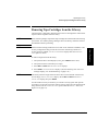
Removing Tape Cartridges from the Library
The tape library is designed to hold from one to three 5-slot magazines. Follow these
steps to remove magazines from the library:
Some software packages require that tape cartridges be inserted and removed using
the software. If a software package manages files in the library, check the software
documentation before proceeding.
NOTE
All drives must be empty before the access door can be released. In addition, some
security configurations may prevent the access door from being released. If a
security option is enabled, SECURITY ENABLED displays after the RELEASE
DOOR option is chosen.
To remove magazines from the library:
1. Verify that the drive status displays (if not, press CANCEL until it does).
2. Verify that all drives in the library are empty.
3. Press NEXT or PREV until RELEASE DOOR displays.
4. Press ENTER. DOOR RELEASED displays. (See the following note. If an error
message displays, see “Troubleshooting” on page 3-38.)
NOTE
The drive(s) must be empty before the access door can be released. If the drive(s)
are not empty, EMPTY DRIVE NO displays. Press NEXT or PREV until EMPTY
DRIVE YES display, then press ENTER.
In some situations it may be necessary to override a security option and open the
access door. To open the access door when a security option prevents the door from
being released, use the OVERRIDE DOOR option under the ADMIN * menu (see
Figure 3-2 on page 3-8).
3-19
Library Operation
NOTE
Operating the Library
Removing Tape Cartridges from the Library
5. Unlock the access door using the key, then open the door.
NOTE
Figure 3-6
Do not let the door fall open. Damage to the door straps may occur.
Opening the Front Access Door
6. Remove the desired magazine by pushing the button at the top of the magazine
handle (see Figure 3-7) and pulling out the magazine.
Figure 3-7
Removing Magazines
3-20
Operating the Library
Removing Tape Cartridges from the Library
7. If necessary, remove tapes from the magazine. Press the button on top of the
magazine, then pull out the tape.
WARNING
Do not attempt to disable the interlocks. If the library is operating with fewer
than three magazines inserted and the door open, the user can be exposed to
Class II laser light emitted from the bar code reader.
8. Shut and lock the access door using the key lock. Make sure the door is shut
completely.
NOTE
3-21
Library Operation
The library INVENTORY CHECK test runs when the access door is completely
closed so that an inventory of tape bar code labels and storage slot locations can be
stored into library memory. This process takes about one minute.
Operating the Library
Viewing Cartridge Bar Code Labels
Viewing Cartridge Bar Code Labels
Bar code label information can be viewed for each tape cartridge in the library using
the control panel. Bar code information displays sequentially by storage slot
number.
To view bar code information:
1. Verify that the drive status displays (if not, press CANCEL until it does).
2. Press NEXT until VIEW BAR CODES * displays, then press ENTER.
###### SLOT # displays. (“######” represents the bar code information, and
“#” represents the first storage slot that contains a bar coded tape cartridge.)
NOTE
If there are no bar coded tape cartridges in the library, LIBRARY EMPTY displays
briefly, then VIEW BAR CODES * displays. Press CANCEL to return to the drive
status indicators (“ready” state).
3. Press NEXT or PREV to scroll through the storage slot locations that contain bar
coded tape cartridges.
4. Press CANCEL twice to return to the drive status indicators (“ready” state).
3-22
Operating the Library
Cleaning the Library Tape Drives
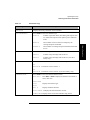
Cleaning the Library Tape Drives
1 2 → ADMIN * → CLEAN DRIVES *
NOTE
Cleaning the drives takes about 5 minutes per drive and requires a special digital
linear tape cleaning cartridge. (Typically, cleaning cartridges are light yellow and
data cartridges are black, brown, or white. See Appendix A for a list of supplies.)
If a cleaning cartridge is not stored inside the tape library, it must be inserted into a
library storage slot before you begin cleaning the drive.
If the cleaning cartridge needs to be replaced, REPLACE CLEANING displays.
The software package may manage drive cleaning.
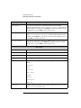
To clean one or more of the drives:
1. Verify that the drive status displays (if not, press CANCEL until it does).
2. Make sure all drives are empty. To empty the drives, refer to the documentation
for the software package.
3. Press NEXT until ADMIN * displays, then press ENTER.
4. Enter the three-part numerical password (see “Entering the Administration
Menu Password” on page 3-9).
5. INFO * displays. Press NEXT until CLEAN DRIVES * displays, then press
ENTER.
•
If the library power has been turned off or the access door has been opened
since a cleaning cartridge location was last selected, SET CLEAN CART*
displays. Press ENTER.
•
If the library power has not been turned off or the access door has not been
opened since a cleaning cartridge location was last selected, CLN CART
LOC # displays (the number of the cleaning cartridge storage slot last
3-23
Library Operation
The drive mechanisms do not require scheduled cleanings and should be cleaned
only if a “clean drive” status indicator displays after the drive number. See
“Understanding Display Window Messages” on page 3-4.
Operating the Library
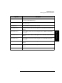
Cleaning the Library Tape Drives
selected is flashing.) If the storage slot location is correct, press ENTER. To
select a different storage slot location, press NEXT until the correct storage
slot location displays, the press ENTER.
6. ###### SLOT # displays (“######” is a barcode number or is blank if
barcodes are not being used, and the storage slot location number is flashing).
Press ENTER to select the displayed storage slot location or press NEXT or PREV
to select a different storage slot location, then press ENTER.
7. CLEAN DRIVE 1 displays and the “1” is flashing. Press NEXT until the drive
number to clean displays, then press ENTER.
To clean both drives, press NEXT or PREV until CLEAN DRIVE ALL displays,
then press ENTER.
NOTE
If the drives are not empty, a DRIVE FULL message displays, and the drives must
be emptied before they can be cleaned.
If the slot location chosen in Step 4 did not contain a cleaning cartridge, NOT
CLEAN CART displays briefly, then CLEAN FAIL # displays. Press CANCEL to
twice to return to the “ready” state. Check the bulk load magazines in the library to
locate the cleaning cartridge. If no cleaning cartridge is present, insert one into an
available slot.
In the event of a drive error, such as a serial communications failure, FAILED
displays and the CLEAN DRIVES * menu displays.
CLEANING DRV # displays (# is the number of the drive being cleaned). When
the drive has been cleaned, CLEANED DRV # displays briefly, then CLEAN
DRIVES * is again displayed.
8. Press CANCEL until the next operation to perform displays, or until the drive
status indicators (library “ready” state) are displayed.
3-24
Operating the Library
Setting Configuration Options
Setting Configuration Options
1 2 → ADMIN * → CONFIG *
You can set certain options to customize the way the library operates. These options
are called configurations.
To change a configuration:
Library Operation
1. Verify that the drive status displays (if not, press CANCEL until it does).
2. Press NEXT until ADMIN * displays, then press ENTER.
3. Enter the three-part numerical password (see “Entering the Administration
Menu Password” on page 3-9).
4. INFO * displays. Press NEXT until CONFIG * displays, then press ENTER.
5. Press NEXT or PREV until the name of the configuration you wish to set displays,
then press ENTER. If the configuration has multiple settings, the current setting
flashes. Otherwise, the configuration option is set and a confirmation message
displays. (Configuration options are described on the following pages.)
If the current configuration setting is flashing, press NEXT or PREV until the
desired setting displays, then press ENTER. OPTION SAVED displays.
6. Press CANCEL to return to the drive status (“ready” state).
The table on the following page describes the available configurations.
3-25
Operating the Library
Setting Configuration Options
Table 3-4
Configuration Options
Config Name
Description
Default
RECOVERY
ON/OFF
If the configuration is set to ON, the library attempts to recover
from errors. If the configuration is set to OFF, the library
immediately stops moving if an error occurs. The default
configuration is RECOVERY ON and should remain ON under
normal conditions.
ON
RESTORE
DEFAULTS
Sets all library configurations back to their default settings.
—
CLEAR
ODOMETERS
Used by service personnel only. Sets all library odometers back to
zero.
—
STARWARS
ON/OFF
Used by service personnel only and should be set to ON during
normal operation. If the configuration is set to ON, the library
runs with the vertical sensors enables. If the configuration is set to
OFF, the library runs with vertical sensors disabled.
ON
NEW PASSWORD
Allows you to change the numerical password required to access
the options under the ADMIN * menu on the library control panel.
These options include configurations, tests, and information logs.
To change the password, see “Setting a New Administration Menu
Password” on page 3-10.
—
SCSI LOG
ON/OFF
Used by service personnel only, and should be set to OFF
during normal operation. Tracks internal SCSI states and saves
the information to a log.
OFF
SECURE ON/OFF
When set to ON, tape magazines cannot be loaded or removed. If
the configuration is set to OFF, the library operates in its default
state, which allows cartridges to be loaded and removed.
OFF
POWER SECURE
ON/OFF
When set to ON, the SECURE ON/OFF configuration setting is
retained in the event of a power outage. If this configuration is set
to OFF, the library returns to its default setting of POWER SECURE
OFF when power is returned after being shut off.
OFF
3-26
Operating the Library
Setting Configuration Options
Config Name
Description
Default
REP RECOVERED
ON/OFF
When set to ON, the recovered errors are reported. When set to
OFF, the recovered errors are not reported.
ON
CONF40 ON/OFF
Used by service personnel only. Do not attempt to use this
configuration – to do so may result in a service call.
—
BARCODE
ON/OFF
When set to ON, the barcodes and slot locations are stored into
library memory when the front access door is closed and the
Inventory Check test runs. When set to OFF, the barcodes are not
recorded when the Inventory Check test runs.
ON
Library Operation
3-27
Operating the Library
Retrieving Performance Information
Retrieving Performance Information
1 2 → ADMIN * → INFO *
Use the INFO * option to display information about the operations of the library.
This information is called a log.
To access an information log:
1. Verify that the drive status displays (if not, press CANCEL until it does).
2. Press NEXT until ADMIN * displays, then press ENTER.
3. Enter the three-part numerical password (see “Entering the Administration
Menu Password” on page 3-9).
4. INFO * displays. Press ENTER.
5. Press NEXT until the name of the log to access displays, then press ENTER. An
asterisk (*) indicates that there are more choices beneath the displayed choice.
6. Press CANCEL to return to the drive status (“ready” state).
3-28
Operating the Library
Retrieving Performance Information
Table 3-5
Information Logs
Log Name
Description
REVISION
Displays the library’s firmware revision number.
LIB ODOMETERS *
Press ENTER to select the odometer logs.
DRIVE FW *
Number of operation hours (time during which power was
on). Some time may have been spent in power reduction
mode.
MOVES #
Total number of moves and move attempts by the
cartridge transport mechanism.
XLATES #
Total number of cartridge transport mechanism horizontal
moves.
Press ENTER to select the logs described in the next few rows.
DRIVE 1
Number of tape cartridge loads for drive 1.
DRIVE 2
Number of tape cartridge loads for drive 2 (two drive
library only).
Press ENTER to select the firmware revision of the drive you want to see.
D1
REVISION # Firmware revision of drive 1.
D2
REVISION # Firmware revision of drive 2 (two drive library only).
INTERFACE FW *
Press ENTER to select the Interface board revision.
BUS NUM = Press NEXT or PREV to display the interface bus number to
select, then view:
FAST WIDE
SCSI
Displays the interface type.
8052
Rev #
Displays the 8052 firmware.
8052 CKSUM # Displays the 8052 checksum revision.
COBRA REV# Displays the revision of the interface chip (Cobra).
3-29
Library Operation
DRIVE LOADS *
HOURS #
Operating the Library
Retrieving Performance Information
Log Name
Description
HARD ERROR *
Log of unrecoverable errors (commands that did not successfully
complete). Returns either NO HARD ENTRIES or ENTRY #. (There may be
multiple hard error numbers.) Press ENTER to view the log for the currently
displayed error, or press NEXT to select the next error.
SOFT ERROR *
Log of recovered errors (commands successfully completed). Returns
either NO SOFT ENTRIES or ENTRY #. (There may be multiple soft error
numbers.) Press ENTER to view the log for the currently displayed error, or
press NEXT to select the next error.
RECOVERY ERROR *
Log of errors during most recent move. Returns either NO ENTRIES or the
number of recovery errors. Press ENTER to view the log for the currently
displayed error, or press NEXT to select the next error.
Error Logs
HARDWARE ERR#
Indicates the cause of the failure.
FRU 1 #
Field replaceable unit most likely to be at fault.
FRU 2 #
Field replaceable unit second most likely to be at fault.
FRU 3 #
Field replaceable unit third most likely to be at fault.
MOTION <name>
<name> indicates the type of movements taking place at the time of the
failure:
EXCHANGE
MOVE
POSITION
INIT ELEM
REZERO
ROTATE
DIAGNOSTIC
RESTORE
Element number to which the source refers. (Valid for MOVE, EXCHANGE,
and POSITION movements only.)
SOURCE #
3-30
Operating the Library
Retrieving Performance Information
Log Name
Description
Element to which the first destination refers. (Valid for MOVE and
EXCHANGE movements only.)
DESTINATION 2 #
Element to which the second destination refers. (Valid for EXCHANGE
movement only.)
ODOMETER #
Move number in which the error occurred.
MICROMOVE 1 #
First library micro-move for the original move command issued before the
failure.
MICROMOVE 2 #
Second library micro-move for the original move command issued before
the failure.
MICROMOVE 3 #
Third library micro-move for the original move command issued before the
failure.
MICROMOVE 4 #
Fourth library micro-move for the original move command issued before
the failure.
MICROMOVE 5 #
Fifth library micro-move for the original move command issued before the
failure.
MICROMOVE 6 #
Last library micro-move for the original move command issued before the
failure.
MICROMOVE ER #
Actual micro-move error that occurred.
3-31
Library Operation
DESTINATION 1 #
Operating the Library
Running an Internal Test
Running an Internal Test
1 2 → ADMIN * → TEST *
The library can run self-diagnostic tests. To run these tests, follow these steps:
CAUTION
Some diagnostic tests can place tape cartridges in unexpected locations. These tests
should be run only by authorized service personnel.
1. Verify that the drive status displays. If not, press CANCEL until it does.
2. Press NEXT until ADMIN * appears in the display window, then press ENTER.
3. Enter the three-part numerical password (see “Entering the Administration
Menu Password” on page 3-9).
4. INFO * displays. Press NEXT or PREV until TEST * displays, then press ENTER.
5. Press NEXT until the name of the test to run displays, then press ENTER.
6. NUM LOOPS # displays, where the 1 is flashing. Press NEXT until the number of
test loops you wish to run displays, then press ENTER.
NOTE
Press CANCEL at any time to abort a test. TEST CANCEL - WAIT displays while the
current test loop completes.
3-32
Operating the Library
Running an Internal Test
Table 3-6
Test Name
Internal Tests
Description
Runs the VERTICAL TEST, TRANSLATE TEST, MAGAZINE IO, and DRIVE
IO tests. Each test is run one time per test loop.
EXCHANGE DEMO
Used by service personnel only. Do not run this test if the library contains
tape cartridges with file system data on them. This test moves randomly
chosen cartridges to random storage slot locations. This test displays FAIL if
there are no cartridges in the library or if all storage slots are full. For best results,
the library should contain as many cartridges as there are drives, plus two
additional cartridges. The transport must be empty.
IO DRIVE
Makes a combination of moves with a PASS/FAIL result. If the drives are
empty, a tape cartridge is moved from a randomly chosen full slot to a randomly
chosen drive. If the drives are full, a tape cartridge is moved from a randomly
chosen drive to a randomly chosen storage slot. It then moves the cartridge back
to its original location. This test displays FAIL if there are no cartridges in the
library or if all storage slots are full. The transport and the mailslot must be
empty.
IO MAGAZINE
Makes a combination of moves with a PASS/FAIL result. It moves a tape
cartridge from a random full slot to a random empty slot. It then moves the tape
cartridge back to its original storage slot. This test displays FAIL if there are no
cartridges in the library or if all storage slots are full. The drives, transport, and
the mailslot must be empty.
IO MAILSLOT
Makes a combination of moves with a PASS/FAIL result. It moves a tape
cartridge from a random full slot to the mailslot. It then moves the tape cartridge
back to its original storage slot. This test displays FAIL if there are no cartridges
in the library or if all storage slots are full. The drives, transport, and the mailslot
must be empty.
INVENTORY
CHECK
Functions the same as the SCSI Initialize Element Status command. This test
physically scans the entire unit to determine which storage slots contain tape
cartridges and if the drives contain cartridges. NOTE: This test will appear as
ISTAT TEST in all front panel error messages.
TEST
TRANSLATE
Translates from side to side. No tape cartridges are required.
TEST VERTICAL
Moves the transport mechanism up and down the full length of the rail. Returns
PASS/FAIL. No tape cartridges are required.
3-33
Library Operation
EXERCISE MECH
Operating the Library
Running an Internal Test
Test Name
Description
WELLNESS TEST
Checks the general capability of the library. Requires one loaded tape cartridge,
but the drives and transport must be empty. Runs INIT MECHANICS and
EXERCISE MECH. Each test is run one time per test loop.
FIND PLUNGE
HOME
Runs mechanism recalibrartion, determines the reference points in the picker
travel path, and tests the picker. This test assumes that the mechanics and servo
system are functional. No tape cartridges are required.
FIND VERT HOME
Recalibrates the vertical position and verifies that the vertical path is clean. No
tape cartridges are required.
FIND XLATE
HOME
Calibrates the translate position. No tape cartridges are required.
INIT
MECHANICS
Runs the FIND PLUNGE HOME, FIND VERTICAL HOME, FIND XLATE HOME,
and INIT ELEM STATUS tests. Each test is run one time per test loop.
EMPTY DRIVES
Used by service personnel only. Do not run this test if the library contains
tape cartridges with actual file system data on them. Moves cartridges out of
the drive mechanism and returns them to their original storage slot locations if the
locations are know, otherwise the cartridges are placed into the first available
storage slot.
EMPTY PICKER
Used by service personnel only. Do not run this test if the library contains
tape cartridges with actual file system data on them. Moves a tape cartridge
from the cartridge transport mechanism to its original storage slot location if the
location is know, otherwise the cartridge is placed into the first available storage
slot.
FILL PICKER
Used by service personnel only. Do not run this test if the library contains
tape cartridges with actual file system data on them. Moves a tape cartridge
into the cartridge transport mechanism from the first storage slot containing a
cartridge.
REWIND MEDIA
Used by service personnel only. Do not run this test if the library contains
tape cartridges with actual file system data on them. Rewinds the tape in the
drive(s) and opens the solenoid in the drive handle, which allows the tape to be
removed from the drive by lifting the handles. If the picker malfunctions, use this
option to get the tapes out of the drive.
CLEAR SOFT LOG
Sets the soft error log to zero.
CLEAR HARD LOG
Sets the hard error log to zero.
3-34
Operating the Library
Running an Internal Test
Test Name
Description
Allows the cartridge transport mechanics to run at full speed. This setting should
always be used under normal library operations.
PLUNGE 1/2 SPD
Used by service personnel only. Allows the cartridge transport mechanics to run
at half speed.
SENSOR
TRANSLATE
Tests the horizontal path that the cartridge transport mechanism follows when
moving from one stack of tape cartridges to another. Displays ON or OFF. If OFF
displays, the sensor is block. (This display is automatically updated if the sensor
status change.) Requires the use of one tape cartridge.
SENSOR
MAGAZINE
The displays shows M1 1 M2 1 M3 1. Each “1” indicates that the caddy is in
place. If a “0” is displayed, the caddy has not been inserted into the library. (This
display is automatically updated if the sensor status changes.)
SENSOR
STARWARS
The display shows 0 0.
VERTICAL
ENCODER
Moves the cartridge transport mechanism down, moves it back up a short
distance, then moves it back down. The last time the transport mechanism is
moved down the number of encoder counts is verified. Returns PASS/FAIL. No
tape cartridges are required.
Each “0” indicates one of the paths that the cartridge transport mechanism
follows in front of each stack of tape cartridges. If the path is clean, a 0 displays;
if the path is blocked (because of a cartridge that is not inserted fully into its
storage slot for example), an * will be displayed. (This display is automatically
updated if the sensor status changes.)
3-35
Library Operation
PLUNGE FULL
SPD
Operating the Library
Using Online Drive Replacement
Using Online Drive Replacement
1 2 → ADMIN * → ONLINE REPAIR *
CAUTION
Unless the situation described below exists, this options should only be used by an
authorized service representative. Using this option causes the library drive
mechanism(s) to become inactive.
Online drive replacement is an important new feature that allows:
•
an authorized service representative to replace a faulty drive while the library is
active
•
a user to clear a drive cleaning error when a tape that may be damaged is in the
drive
This feature should only be used by an authorized service representative. However,
if an older, frequently used tape causes a drive cleaning message to be displayed
more than once and you suspect the tape is damaged, use the “Online Repair” option
can be used to clear the drive error message so you can attempt to recover data from
the damaged tape.
To use this option to clear a drive cleaning error:
1. With CLEAN DRV # displayed, press CANCEL until the drive status displays. (#
is the drive number containing the damaged tape.)
2. Press NEXT until ADMIN * displays, then press ENTER.
3. Enter the three-part numerical password (see “Entering the Administration
Menu Password” on page 3-9).
4. INFO * displays. Press NEXT or PREV until ONLINE REPAIR * displays, then
press ENTER. DRIVE POWER * displays.
3-36
Operating the Library
Using Online Drive Replacement
5. Press NEXT or PREV until DRIVE STATUS displays, then press ENTER. DRV 1
ON GOOD displays.
•
If the damaged tape is in drive 1, press ENTER.
•
If the damaged tape is in drive 2, press NEXT until DRV 2 ON GOOD displays,
then press ENTER.
DRV # ON GOOD displays, where “#” is the drive number and ON GOOD is
flashing.
6. Press NEXT until DRV # OFF FAILED displays then press ENTER.
8. DRIVE POWER * displays.
9. Press NEXT or PREV until DRIVE STATUS displays, then press ENTER.
10. Press NEXT or PREV until DRV # OFF FAILED displays (where “#” is the
number of the drive that was just taken off-line) then press ENTER.
11. DRV # OFF FAILED displays, where “#” is the drive number and OFF
FAILED is flashing.
12. Press NEXT until DRV # ON GOOD displays, then press ENTER.
13. SETTING UP DRIVE displays briefly while the drive communication tests run,
following by CHANGE CONFIRMED and then ONLINE REPAIR *.
14. Press CANCEL twice to return to the drive numbers and status indicators (“ready”
state).
15. Try reading the damaged tape again.
•
If the tape can be read, back up data from the damaged cartridge to another
tape cartridge and discard the damaged one.
•
If the tape cannot be read, call your service representative.
3-37
Library Operation
7. CHANGE CONFIRMED displays briefly, then ONLINE REPAIR * displays.
Press ENTER.
Operating the Library
Troubleshooting
Troubleshooting
This section provides information on solutions to problems that may occur in the
operation of the library. Table 3-7 lists steps the administrator should take before
consulting a service representative.
NOTE
If you decide that a service call is needed, write down the library serial number
before calling. The serial number is located on a label towards the bottom of the
library on the library rear panel.
For problems that may be related to the computer, refer to the host computer system
documentation or library application software instructions.
Table 3-7
Troubleshooting Table
Problem
Library will not power on.
Power-on test failed.
What to do
•
Make sure the power cord connections are tight.
•
Make sure the power switch is switched on. (The power
switch is located on the library control panel.)
•
Make sure the power outlet is operating.
•
Replace the power cord with a known good one.
•
If the library still won’t power on, call a service
representative.
•
Verify that all tapes in the bulk load magazines are fully
inserted in the magazines, and that the magazines are
securely locked into position inside the tape library.
•
Press the power switch off and then on again. (See the
caution note at the end of this table.)
•
If the power-on test continues to fail, press ENTER, write
down the displayed error code, and call a service
representative for assistance.
DEVICE FAILED displays.
3-38
Operating the Library
Troubleshooting
Problem
What to do
•
Hardware Error #61 (External SCSI
cables) is reported.
Make sure that only one SCSI device type (single-ended OR
differential) exists on the SCSI bus.
•
Verify that the library SCSI selector switch is set correctly
(either single-ended or differential).
•
Verify that the mode switch termination is set correctly.
The library’s power failed while a
cartridge was in the drive and did not
return to the drive status indicators
("ready" state) after the power came
back on.
•
Press the power switch off and then on again. (See the
caution note at the end of this table.)
•
If the power-on test is unsuccessful, switch off the power.
Call a service representative for assistance.
No display messages appear.
•
Make sure the power cord is connected.
•
Make sure the power switch is on.
•
Power cycle the library. (See the caution note at the end of
this table.)
•
If there is still no display, call a service representative for
assistance.
3-39
Library Operation
DEVICE FAILED displays.
Operating the Library
Troubleshooting
Problem
An error message is received after
bulk loading tape cartridges.
What to do
•
Verify that cartridges are inserted into the magazine in the
correct orientation. (See “Loading Tape Cartridges Into
the Library” on page 3-15.)
•
Verify that the correct tape type is used. (See “Choosing
Tape Cartridges” on page 2-3.)
•
If the light bar on the display panel is orange, cycle power to
the library and try to load the magazine again when the drive
numbers and status indicators are displayed. (See the
caution note at the end of this table.)
•
If SECURITY ENABLED displays, a security option has
been set that prevents cartridges from being loaded into or
removed from the library. See “Setting Configuration
Options” on page 3-25.
•
If TRANSPORT FULL displays, the cartridge transport
mechanism already contains a tape cartridge. Refer to the
host documentation or call a service representative to
remove the cartridge from the transport.
•
If a LOAD ERROR or FAILED message still displays, this
could indicate a library failure; call a service representative
for assistance.
Changed drive address but the new
address is not recognized.
Try rebooting the host computer. Some computers require this
for the new address to be recognized. (See the caution note at
the end of this table.)
Cannot remember the administration
menu password.
First, try the default password (000-000-000). If the default is
not accepted, call a service representative for assistance.
Attempted to open the front access
door, but a RESERVED message
displays.
•
The host may have reserved an element and must unreserve
it. Refer to the host system documentation to unreserve a
tape.
•
A security configuration was set to prevent cartridge
removal. See SECURE ON/OFF in the list of configurations
found in “Setting Configuration Options” on page 3-25.
Started a test and need to stop.
3-40
Press CANCEL. The current test loop continues until finished,
then the test stops.
Operating the Library
Troubleshooting
Problem
DO INVENTORY TEST displays
(initialize element status).
Cannot write to the tape.
CAUTION
•
Power cycle the library by pressing the power switch off and
then on again. (See the caution note at the end of this
table.)
•
Run the INVENTORY CHECK test under the TEST * menu.
•
Check the host file system access permissions.
•
Check the write-protect tab on the cartridge to assure
write-enabled status.
•
Check the application software.
•
Check the host file system access permissions.
•
Verify that the correct tape type is used (See “Choosing
Tape Cartridges” on page 2-3.)
•
Check the application software.
Library Operation
Cannot read the tape.
What to do
Do not press the library power switch until all SCSI peripherals connected to host
are shut down. Pressing the power button when the SCSI system is active can cause
data loss and/or problems with the SCSI interface.
3-41
Operating the Library
Troubleshooting
3-42
Supplies & Support
A
Supplies and Customer Support
A-1
Supplies and Customer Support
Overview
Overview
This appendix covers:
• supplies and accessories (page A-3)
• HP customer support information (page A-6)
A-2
Supplies and Customer Support
Supplies and Accessories
Supplies and Accessories
A full range of supplies may be ordered through a Hewlett-Packard authorized
dealer, sales office, or through HP Direct. To contact HP Direct, call
1-800-227-8164 or write to HP Direct at the following address:
HP Direct
Hewlett-Packard
attn: Mail Order
P.O. Box 1145
Roseville, CA 95678
Call 1-800-752-0900 for the location of the nearest authorized Hewlett-Packard
dealer.
Table A-1
Basic Supplies and Accessories
Part Number
Supplies & Support
Item
Bulk Load Magazine
5-slot removable magazine with 5 HP DLT tape IV
cartridges
C5148F
5-slot removable magazine, empty
C5149F
Tape Cartridges
HP DLT Tape IV Data Cartridge with 35 Gbyte/20 Gbyte
Native Capacity
C5141F
HP DLT Tape III XT Data Cartridge with 15 Gbyte
native capacity
C5141A
Cleaning Tape Cartridge
C5142A
A-3
Supplies and Customer Support
Supplies and Accessories
Item
Part Number
Bar Code Labels
Bar Code labels are not available through
Hewlett-Packard, but may be ordered through other
companies (see sample labels shipped in the accessories
kit). When ordering, make sure the bar code labels meet
the following specifications:
N/A
Message: 6-character (2 alpha, 4 numeric)
Dimensions: 2.2 in. x .82 in.
Symbology: code 39 without check digit
Start/Stop Characters: */*
Narrow Bar: 0.014 in.
Ratio: 2:5:1
Print Quality: ANSI Grade “A”
SCSI Cables (68-pin to 68-pin)
.9 m (2.9 ft) SCSI cable, high-density with thumb screws
to high-density with thumb screws, m-m
C2911A
2.5 m (8.2 ft) SCSI cable, high-density with thumb screws
to high-density with thumb screws, m-m
C2924A or
D3636A
10m (32.8 ft) SCSI cable, high-density with thumb
screws to high density with thumb screws, m-m
C2925A
20m (65.6 ft) SCSI cable, high-density with thumb
screws to high density with thumb screws, m-m
C2926A
Jumper cable: 0.16 m SCSI cable; wide high-density with
thumb screws to high-density with thumb screws, m-m
C5172-61606
Mounting Kits
Rack mounting kit for mounting into a standard 19-inch
rack
A-4
C5157F
Supplies and Customer Support
Supplies and Accessories
Item
Part Number
Drive Upgrade Kits
DLT 4000 - 1 Drive upgrade kit (upgrades 4115 to 4215)
C5174F
DLT 7000 - 1 Drive upgrade/conversion kit (upgrades
7115 to 7215; converts 4x15 to 7115)
C5174J
User’s Guide (replacement/additional)
C5173-90000
Supplies & Support
A-5
Supplies and Customer Support
Hewlett-Packard Customer Support
Hewlett-Packard Customer Support
If a DLT library fails during the warranty period, and the troubleshooting guide and
user manual does not solve the problem, you can receive support by doing the
following:
•
Consult HP FIRST or QUICK FAX for faxback services. See “HP
FIRST/QUICK FAX Faxback Services” on page A-6.
•
Consult one of the computer/modem connectivity services available, such as
America Online or CompuServe. See “Electronic Support Services” on page
A-9.
•
Consult one of the customer support centers in your area for standard or post
warranty work. See “Customer Support Centers” on page A-10.
If the library fails after the warranty period, contact your authorized HP
dealer/distributor or the nearest HP sales and service office. Customers in the US
and Europe can also use a credit card for phone assistance.
HP FIRST/QUICK FAX Faxback Services
QUICK FAX and HP FIRST are automated systems that fax requested product
information and/or technical support documents to you. These faxback services are
available 24 hours/day.
To use this service, dial the appropriate fax number below for your country from a
touch-tone phone. Follow the voice prompts to select an index of available support
and product documents.
NOTE
Remember to dial the country code before these numbers.
A-6
Supplies and Customer Support
Hewlett-Packard Customer Support
Asia-Pacific
(03) 9272 2627
China
(81610) 65055280
Hong Kong
800-7729
India
(011) 622 6420
Indonesia
6221-350-3408
Japan
(3) 3335-8622
Korea
(02) 769-0543
Malaysia
800-1611
New Zealand
(09) 356 6642
Philippines
636-867-3551
Singapore
(65) 291-7951
Taiwan
(02) 719 5589
Thailand
(02) 661 4011
Vietnam
001- (84) 823-4530
Supplies & Support
Australia
A-7
Supplies and Customer Support
Hewlett-Packard Customer Support
Europe
Austria
06 60 63 86
Belgium, Dutch
0800 11906
Belgium, French
0800 17043
Denmark
800 10453
Finland
0800 13134
France
05 905900
Germany
0130 810 061
Ireland
01 662 5525
Italy
1678 59020
Netherlands
06 022 2420
Norway
800 11319
Portugal
01 441 7199
Spain
900 993123
Sweden
020 795743
Switzerland,
German
0800 55 1527
Switzerland,
French
0800 55 1526
United Kingdom
0800 960271
Other locations in
Europe
31 20 681 5792
North and South America (includes Canada)
(800) 368-9673 or (970) 635-1510
Other Countries
(970) 635-1510
A-8
Supplies and Customer Support
Hewlett-Packard Customer Support
Electronic Support Services
For 24-hour access to information over your modem:
On-line Service Providers
Technical information is available on CompuServe and America Online.
Service Provider
Description
Address
CompuServe
To download software, firmware,
and support documents, and to
discuss issues in user forums.
GO HPSYS
America Online
To download software, firmware,
and support documents, and to
discuss issues in user forums.
GO HPSTOR
Supplies & Support
Hewlett-Packard Web Site
Product and support information is available on the Hewlett-Packard web site:
Support and Product information: http://www.hp.com/go/tape
Global support: http://globalsupt.mayfield.hp.com/
A-9
Supplies and Customer Support
Hewlett-Packard Customer Support
Customer Support Centers
NOTE
Contact the customer support center in your area for technical assistance during the
warranty of your product.
North and South America (includes Canada)
Monday - Friday, 6am - 6pm MST
HP Colorado Tape Drive and SureStore CD drivers (970) 635-1500
DLT Tape Drives (970) 635-1000
European Customer Support Centers
Monday - Friday, 8:30 - 18:00 (C.E.T)
NOTE
Language or country support might not be available for all products.
Austria
06 60 63 86
Belgium, Dutch
02 626 8806
Belgium, French
02 626 8807
Denmark
3929 4099
Finland
0203 47 288
France
01 43 62 34 34
Germany
0180 52 58 143
Ireland
01 662 5525
Italy
02 264 10350
Netherlands
020 606 8751
Norway
22 11 6299
Portugal
7095 923 50 01
Spain
902 321 123
Sweden
08 619 2170
Switzerland
0848 80 11 11
United Kingdom
0800 960271
A-10
Supplies and Customer Support
Hewlett-Packard Customer Support
Asia-Pacific
+64 (0) 3 9282 8000
China
+85 (0) 10 6505 3888
Hong Kong
+85 (0) 2 2802 4098
800 96 7729
India
+ 91 (0) 11 682 6035
Indonesia
+62 (0) 21 350 3408
Japan
+81 (0) 3 3335 8333
Korea
+82 (0) 2 3270 0700
Outside Seoul: 080 999 0700
Malaysia
+60 (0) 3 295 2566
New Zealand
+64 (0) 9 356 6640
Philippines
+63 2 867 3551
Singapore
+65 (0) 272 5300
Taiwan
+886 (0) 2 717 0055
Thailand
+66 (0) 2 661 4011
Supplies & Support
Australia
Elsewhere
Contact your authorized HP dealer/distributor or the nearest HP sales and service
office.
A-11
Supplies and Customer Support
Hewlett-Packard Customer Support
Telephone Support After Warranty
Before Calling
Before calling, please complete the following information so that you will have it
ready for the support center representative:
•
Serial number of product ____________________
•
Brand and model of host computer ________________________
•
Version of software used; driver selected ________________________
US and Canada
Using a VISA or MasterCard, call one of the following:
•
(800) 810-0130: Per incident fee of $25.00 will be charged to the credit card.
•
(900) 555-1800: $2.50 per minute with a maximum of $25.00 will be charged to
the credit card.
Europe
Call the appropriate number listed under “European Customer Support Centers” on
page A-10. A per incident fee will be charged for after-warranty support. Please
have a credit card, PO number, or billing number address ready.
Elsewhere
Contact your authorized HP dealer/distributor or the nearest HP sales and service
office for after-warranty support.
HP Reseller Locator Numbers
US
(800) 752-0900
Canada
(800) 387-3867
Mexico and South
America
(305) 267-4220
A-12
Safety and Regulatory
B
Safety and Regulatory
Information
B-1
Safety and Regulatory Information
Overview
Overview
This section contains important safety and regulatory information for
the United States, Finland, Sweden, European Union, and Japan.
B-2
Safety and Regulatory Information
Safety Information
Safety Information
Laser Safety
WARNING
Do not attempt to disable the interlocks or open the service
panels while library power is turned on. If the library is
operating with the service panels removed, or with fewer than
three magazines inserted and the door is open, you can be
exposed to Class II laser light emitted from the bar code reader.
CDRH Regulations (USA Only)
The Center for Devices and Radiological Health (CDRH) of the U.S. Food
and Drug Administration implemented regulations for laser products on
August 2, 1976. These regulations apply to laser products manufactured
from August 1, 1976. Compliance is mandatory for products marketed in
the United States. The labels and artwork shown below indicate
compliance with CDRH regulations and must be attached to laser
products marketed in the United States.
WARNING
Use of controls, adjustments or performing procedures other
than those specified in this manual may result in hazardous
laser radiation exposure.
Laser Class Information: A black on yellow label that reads, “Class 1
Laser Product” printed in English, French, German, Finnish, Japanese,
and Spanish.
B-3
Safety and Regulatory
Complies with 21 CFR Chapter 1 Subchapter J.
Safety and Regulatory Information
Regulatory Information
Regulatory Information
B-4
Safety and Regulatory Information
Regulatory Information
Declaration of Conformity
Safety and Regulatory
B-5
Safety and Regulatory Information
Regulatory Information
United Kingdom Telecommunications Act 1984
The digital linear tape libraries are approved under Approval Number
NS/G/1234/J/100003 for indirect connection to Public Telecommunication Systems
within the United Kingdom.
Herstellerbescheinigung
Diese Information steht im Zusammenhang mit den Anforderungen der
Maschinenlärn information sverordnung vom 18 Januar 1991.
Schalldruckpegel Lp < 70 dB(A)
•
am arbeitsplatz
•
normaler betrieb
•
nach ISO 7779: 1988/EN 27779:1991 (Typprüfung)
English Translation of German Sound Emission Directive
This statement is provided to comply with the requirements of the German Sound
Emission Directive, from 18 January 1991.
Sound pressure Lp < 70 dB(A)
•
at operator position
•
normal operation
•
according to ISO 7779: 1988/EN 27779: 1991 (type test)
B-6
Safety and Regulatory Information
Regulatory Information
Turvallisuusyhteenveto
Laserturvallisuus
LUOKAN 1 LASERLAITE
KLASS 1 LASER APPARAT
HP DLT Tape Library -nauhamuistiasemat ovat käyttäjän kannalta turvallisia
luokan 1 laserlaitteita. Nauhamuistiasemien sisälle asennettu lasersädettä käyttävä
viivakoodinlukija ei normaalissa käytössä aiheuta vaaraa käyttäjälle.
Laitteiden turvallisuusluokka on määritetty standardin EN 60825-1 (1994)
mukaisesti.
VAROITUS !
Laitteen käyttäminen muulla kuin käyttöohjeessa mainitulla tavalla saattaa altistaa
käyttäjän turvallisuusluokan 1 ylittävälle lasersäteilylle.
VARNING !
Om apparaten används på annat sätt än i bruksanvisning specificerats, kan
användaren utsättas för laserstrålning som överskrider gränsen för laserklass 1.
HUOLTO
VARO !
Nauhamuistiaseman suojakotelon ollessa avattuna saatat altistua lasersäteilylle
viivakoodinlukijan toimiessa. Älä tuijota säteeseen.
VARNING !
När skyddshöljet av magnetbandstationen är öppnad, kan användaren utsättas för
laserstrålning då streckkodläsare är i funktion. Stirra ej in i strålen.
Tiedot viivakoodinlukijassa käytettävän laserdiodin säteilyominaisuuksista:
Aallonpituus675 nm
Teho0,5 mW
TurvallisuusluokkaLuokan 2 laser
B-7
Safety and Regulatory
HP DLT Tape Library -nauhamuistiasemien sisällä ei ole käyttäjän huollettavissa
olevia kohteita. Laitteen saa avata ja huoltaa ainoastaan sen huoltamiseen koulutettu
henkilö. Nauhamuistiaseman sisälle asennettua viivakoodinlukijaa ei tule avata eikä
purkaa huoltotoimenpiteiden yhteydessä.
Safety and Regulatory Information
Regulatory Information
English Translation of Finnish Regulatory Information
LASER SAFETY SUMMARY
LASER SAFETY
CLASS 1 LASER PRODUCT (The same text in Swedish)
HP DLT Tape Library Systems are for user safe class 1 laser products. In normal use
the laser bar code reader installed inside the tape library units doesn’t cause any
hazard to the user.
The laser safety class of the libraries was defined in accordance with the standard
EN 60825-1 (1994).
WARNING!
The use of the product otherwise than specified in the user’s manual may expose the
user to laser radiation exceeding safety class 1.
(THE SAME WARNING IN SWEDISH)
SERVICE
There are no user serviceable parts inside the HP DLT Tape Library units. The DLT
units can be serviced only by qualified service personnel. The laser bar code reader
installed inside the library units shall not be opened or disassembled during service.
WARNING!
If the enclosure of the tape library unit is opened, you may be exposed to laser
radiation when the bar code reader is operating. Don’t stare into the beam.
(THE SAME WARNING IN SWEDISH)
The information about the radiation characteristics of the laser diode used in the
laser bar code reader:
Wavelength675 nm
Power0,5 mW
Laser safety classClass 2 laser
B-8
Safety and Regulatory Information
Regulatory Information
Japanese VCCI Statement
English Translation of Japanese VCCI Statement
This equipment is in the Class B category information technology equipment based
on the rules of Voluntary Control Council For Interference by Information
Technology Equipment (VCCI). Although aimed for residential area operation,
radio interference may be caused when used near a radio or TV receiver. Read the
instructions for correct operation.
Safety and Regulatory
B-9
Safety and Regulatory Information
Regulatory Information
B-10
TapeAlert Messages
C
TapeAlert Messages
C-1
TapeAlert Messages
Overview
Overview
This section contains information on TapeAlert, a diagnostic tool that
monitors the drive’s operations, checks media integrity, and send
messages via your backup software to warn you of existing or potential
problems.
C-2
TapeAlert Messages
TapeAlert Messages and Descriptions
TapeAlert Messages and Descriptions
There are three types of messages, listed in order of severity. They are
information (I), warning (W), and Critical (C). Information messages
explain a diagnostic situation. Warning messages appear when data may
be lost. Critical messages describe the most severe situations, and
require immediate attention.
Table C-1
No.
TapeAlert Tape Error Messages
Flag
Type
Displayed Message
Additional Action
Information
Read
Warning
W
The tape is having
problems reading data. No
data has been lost, but
there has been a reduction
in the performance of the
tape.
Back up information on to
another tape and discard
the defective tape. If the
problem persists, call the
tape drive supplier
helpline.
2
Write
Warning
W
The tape drive is having
problems writing data. No
data has been lost, but
there has been a reduction
in the capacity of the tape.
Back up information on to
another tape and discard
the defective tape. If the
problem persists, call the
tape drive supplier
helpline.
3
Hard Error
W
The operation has stopped
because an error has
occurred while reading or
writing data which the
drive cannot correct.
Back up information on to
another tape and try the
operation again. If the
problem persists, call the
tape drive supplier
helpline.
5
Read Failure
C
The tape is damaged or the
drive is faulty. Call the tape
drive supplier helpline.
Eject the tape and inspect
for damage. Insert a new
tape and try operation
again.
C-3
TapeAlert Messages
1
TapeAlert Messages
TapeAlert Messages and Descriptions
No.
6
Flag
Type
Write
Failure
C
Displayed Message
The tape is from a faulty
batch or the tape drive is
faulty:
1. Use a good tape to test
the drive.
Additional Action
Information
Eject the tape and inspect
for damage. Insert a new
tape and try operation
again.
2. If the problem persists,
call the tape drive
supplier helpline.
9
Write
Protect
C
You are trying to write to a
write-protected cartridge.
Remove the
write-protection or use
another tape.
Insert a new tape and try
operation again.
If the problem persists, call
the tape drive supplier
helpline.
10
No Removal
I
You cannot eject the
cartridge because the tape
is in use. Wait until the
operation is complete
before ejecting the
cartridge.
If the problem persists, call
the tape drive supplier
helpline.
11
Cleaning
Media
I
The tape in the drive is a
cleaning cartridge. If you
want to back up or restore,
insert a data-grade tape.
If the problem persists, call
the tape drive supplier
helpline.
C-4
TapeAlert Messages
TapeAlert Messages and Descriptions
No.
20
Flag
Clean Now
Type
C
Displayed Message
The tape drive needs
cleaning:
1. If the operation has
stopped, eject the tape
and clean the drive.
Additional Action
Information
If the problem persists, call
the tape drive supplier
helpline.
2. If the operation has not
stopped, wait for it to
finish and then clean the
drive.
Check the tape drive users
manual for device specific
cleaning instructions.
22
Expired
Cleaning
Media
C
The last cleaning cartridge
used in the tape drive has
worn out:
Wait for the current
operation to finish before
discarding the cartridge.
1. Discard the worn out
cleaning cartridge.
If the problem persists, call
the tape drive supplier
helpline.
2. Wait for the current
operation to finish.
3. Then use a new cleaning
cartridge.
TapeAlert Messages
C-5
TapeAlert Messages
TapeAlert Messages and Descriptions
No.
31
Flag
Type
Hardware B
C
Displayed Message
The tape drive has a
hardware fault:
1. Turn the tape drive off
and then on again.
Additional Action
Information
Power off the tape drive
and attempt the operation
again.
2. Restart the operation.
3. If the problem persists,
call the tape drive
supplier helpline.
Check the tape drive users
manual for device specific
instructions on turning the
device power on and off.
32
Interface
W
The tape drive has a
problem with the host
interface:
If the problem persists, call
the tape drive supplier
helpline.
1. Check the cables and
cable connections.
2. Restart the operation.
34
Download
Fail
Table C-2
W
The firmware has failed
because you have tried to
use the incorrect firmware
for this tape drive. Obtain
the correct firmware and
try again.
TapeAlert Library Error Messages
C-6
Call the tape drive supplier
helpline for more
information.
TapeAlert Messages
TapeAlert Messages and Descriptions
No.
1
Flag
Hardware A
Type
C
Displayed Message
The library mechanism is
having difficulty
communicating with the
drive.
Additional Action
Information
Inspect the library to make
sure all cable and power
connections are secure and
tapes inserted correctly.
1. Turn the library off then
on.
2. Restart the operation.
3. If the problem persists,
call the library supplier
helpline.
2
Hardware B
W
There is a problem with the
library mechanism. If the
problem persists, call the
library supplier helpline.
Inspect the library to make
sure all connections are
secure and tapes inserted
correctly.
3
Hardware C
C
The library has a hardware
fault:
If the problem persists, call
the library supplier
helpline.
1. Reset the library.
2. Restart the operation.
Check the library users
manual for device specific
instructions on resetting
the device.
TapeAlert Messages
C-7
TapeAlert Messages
TapeAlert Messages and Descriptions
No.
4
Flag
Type
Hardware D
C
Displayed Message
The library has a hardware
fault:
1. Turn the library off and
then on again.
Additional Action
Information
Inspect the library to make
sure all connections are
secure and tapes inserted
correctly.
2. Restart the operation.
3. If the problem persists,
call the library supplier
helpline.
Check the library users
manual for device specific
instructions on turning the
device power on and off.
6
Library
Interface
C
The library has a problem
with the host interface:
1. Check the cables and
cable connections.
If the problem persists, call
the library supplier
helpline.
2. Restart the operation.
13
Library Pick
Retry
C-8
W
There is a potential
problem with a drive
ejecting cartridges short or
with the library mechanism
picking a cartridge from a
slot. This warning is for
information purposes only.
No action needs to be taken
at this time. If the problem
persists, call the tape drive
supplier helpline.
Inspect the library to see if
any visible problems exist.
Insert a cartridge and try
the operation again.
TapeAlert Messages
TapeAlert Messages and Descriptions
No.
14
15
Flag
Library
Place Retry
Library
Load Retry
Type
W
W
Displayed Message
Additional Action
Information
There is a potential
problem with the library
mechanism placing a
cartridge into a slot. This
warning is for information
purposes only. No action
needs to be taken at this
time. If the problem
persists, call the tape drive
supplier helpline.
Inspect the library to see if
any visible problems exist.
There is a potential
problem with a drive or the
library mechanism loading
cartridges, or an
incompatible cartridge.
Inspect the library to see if
any visible problems exist.
Insert a cartridge and try
the operation again.
Inspect the cartridge to
verify compatibility.
Insert a cartridge and try
the operation again.
Call the library supplier
helpline if problems persist.
16
Library Door
C
The operation has failed
because the library door is
open:
1. Clear any obstructions
from the library door.
Inspect the library to see if
any visible problems exist.
Insert a cartridge and try
the operation again.
TapeAlert Messages
2. Eject any magazine and
then insert it again.
3. If the fault does not clear,
turn the library off and
then on again.
4. If the problem persists,
call the library supplier
helpline.
C-9
TapeAlert Messages
TapeAlert Messages and Descriptions
No.
Flag
Type
Displayed Message
Additional Action
Information
17
Library
Mailslot
C
There is a mechanical
problem with the library
media import/export
mailslot.
Inspect the library to see if
any visible problems exist.
Insert a cartridge and try
the operation again. Call
the library supplier
helpline.
18
Library
Magazine
C
The library cannot operate
without the magazine.
Refer to user’s manual for
library operation
instructions about
inserting magazines.
1. Insert the magazine into
the library.
2. Restart the operation.
Call the library supplier
helpline.
20
Library
Security
Mode
I
The security mode of the
library has been changed.
The library has either been
put into secure mode, or the
library has exited the
secure mode. This is for
information purposes only.
No action is required.
Check the user’s manual to
verify library configuration.
21
Library
Off-line
I
The library has been
manually turned off-line
and is unavailable for use.
Power the library on to use.
22
Library
Drive
Off-line
I
A drive inside the library
has been taken off-line.
This is for information
purposes only. No action is
required.
If drive is desired for use,
power the library on.
C-10
TapeAlert Messages
TapeAlert Messages and Descriptions
No.
23
Flag
Library
Scan Retry
Type
I
Displayed Message
There is a potential
problem with the barcode
label or the scanner
hardware in the library
mechanism.
Additional Action
Information
Eject the tape and verify
that the barcode label is in
place and undamaged.
Insert the tape and retry
the operation.
Call the library supplier
helpline.
24
Library
Inventory
C
The library has detected an
inconsistency in its
inventory.
Call the library supplier
helpline if problems persist.
1. Redo the library
inventory to correct
inconsistency.
2. Restart the operation.
Check the applications
users manual or the
hardware users manual for
specific instructions on
redoing the library
inventory.
25
W
A library operation has
been attempted that is
invalid at this time.
Call the library supplier
helpline if problems persist.
TapeAlert Messages
Library
Illegal
Operation
C-11
TapeAlert Messages
TapeAlert Messages and Descriptions
C-12
Glossary
A
autochanger. See tape library.
autochanger controller. The
part of the library that controls the
sending and receiving of SCSI
commands and controls the picker.
driver. A program that allows the
operating system to communicate
with a peripheral device.
E
element . A SCSI term for any one
of the autochanger components-drive, storage slots, or picker.
B
bulk load magazine. See
magazine.
J
jukebox. See tape library.
C
L
cartridge . A plastic enclosure
that contains the digital linear
tape. The tape is never removed
from the cartridge.
library. See tape library.
cleaning cartridge. A special
tape cartridge that is used to clean
digital linear tape drives.
LAN. Local Area Network. A
group of computers and
peripherals physically connected
so users can share hardware and
software resources.
M
control panel. The part of the
library that is used to manage and
display library functions.
D
magazine. A removable part of
the library used to insert, remove,
and store tape cartridges in the
library.
Glossary
digital linear tape. Digital linear
tape (DLT) drives read and write
data to digital linear tape in
straight tracks that run the full
length of the tape. The read/write
head moves vertically to read from
or write to the tracks on the tape.
Glossary-1
Glossary
P
peripheral device . A product
used in conjunction with a
computer, that is physically
separate but that is under the
computer’s control. It is usually
connected to the computer by
cables or wires. Printers, disk
drives, scanners, libraries, and
modems are examples of
peripheral devices.
picker. See transport mechanism.
R
rack. A cabinet-like product used
to house one or more computer
peripherals. Computer peripherals
are mounted to special brackets or
rack slides which allow the
peripherals to be installed into the
rack.
rack slides. Expandable
mechanical devices that are
mounted to a computer peripheral
and allow the peripheral to be
installed into a rack which can
house multiple computer
peripheral devices. The rack
slides allow the peripheral to be
extended out of the rack for
service.
Glossary-2
rails. The vertical slotted metal
pieces at the front and back of a
rack used to mount the rack slides
to the rack.
S
SCSI. An acronym for the Small
Computer Systems Interface.
slides. See rack slides.
storage slot. An area of the
magazine that holds cartridges
when the cartridges are not in the
drive.
swap. A motion that occurs when
the transport mechanism replaces
one tape cartridge in the drive
with another, returning the first to
its storage slot.
Glossary
T
U
tape library. A term synonymous
with jukebox or autochanger. This
type of tape storage device is often
referred to as a “jukebox” because
when a file is requested, the tape
cartridge containing the file is
found, inserted into the drive, and
the requested information is sent
to the host computer system. This
is similar to the way a musical
jukebox finds a record and moves it
to the turntable when a song is
requested.
UPS . Uninterruptible Power
Supply. A product that is used to
supply power to computer systems
when there is a power failure.
W
write-protect. A feature that
prevents data from being written
to a tape. A write protect tab is
located on the tape cartridge to
enable write-protection of the tape.
terminator. A resistor array
device used for electrically
terminating a SCSI bus. A SCSI
bus must be terminated at its two
physical ends. A peripheral device
uses a terminator only if it is at the
end of the bus.
transport mechanism. The part
of the library that transports tape
cartridges to and from storage
slots and the drive.
Glossary
Glossary-3
Glossary
Glossary-4
Index
A
accessories, A-3
ADMIN * menu , 3-6
entering the password, 3-9
B
backup software, 1-27
bar code labels
labeling cartridges, 2-4
labeling magazines, 2-5
viewing from display window,
3-22
barcodes, viewing, 3-22
C
cables
routing , 1-23
changing the password, 3-10
cleaning messages, 2-7
cleaning the drives, 3-23–3-24
clearance, 1-3
configuration options, 3-25
configuring the library, 3-25
connecting the tape library, 1-23
contacing support, A-6
control panel
menu, 3-8
control panel keys, 3-3
conventions
typographical, iv
D
display window
description of, 3-3
display window messages, 3-4
drive cleaning messages, 2-7
drive status, 3-4
drives
cleaning, 3-23–3-24
replacing online, 3-37
Index
E
environment, 1-3
online support, A-9
overview, iii
H
host SCSI card, 1-7
P
part numbers, 1-4, A-3
parts, 1-4
additional components
provided, 1-5
password, entering, 3-9
password, setting, 3-10
performance logs
displaying, 3-28
power cables
routing, 1-23
powering on, 1-27
printing history, ii
problems, troubleshooting table,
3-39–3-42
I
information logs
accessing, 3-28
installation
overview , 1-2
installation overview, 1-2
internal tests, 3-33–3-36
K
keys, menus available, 3-8
L
labeling tapes, 2-4, 2-5
library
performance information, 3-28
removing tapes, 3-19
shipping , 1-28
loading tapes, 3-15–3-18
location criteria, 1-3
M
magazines
labeling , 2-5
menu options, 3-6
menu tree, 3-8
messages, display window, 3-4
mode switch
setting , 1-20
mounting the library
rackmounting instructions, 1-8
moving the library, 1-28
O
online drive replacement, 3-37
R
rackmounting , 1-8–1-19
attaching rack slides, 1-12
mounting brackets, 1-10
placing library in rack, 1-17
rear panel, 1-6
regulatory information, B-3–B-9
retrieving performance
information, 3-28
routing SCSI and power cables,
1-23
S
safety and regulatory
information, B-3–B-9
SCSI addresses
setting, 3-11–3-13
viewing current, 3-14
SCSI bus host adapter, 1-7
SCSI bus status indicators, 3-14
SCSI cables
routing, 1-23
SCSI interface mode switch
1
Index
setting, 1-20
SCSI PCA
status indications, listing of,
3-14
security code, setting, 3-23
setting SCSI IDs, 3-11–3-13
setting the mode switch, 1-20
shipping the library, 1-28
status, drive, 3-4
supplies, A-3
support, A-6
telephone, A-12
support centers, A-10
V
viewing barcodes, 3-22
viewing SCSI IDs, 3-14
voltage, 1-3
T
tape drives
cleaning, 3-23–3-24
tape library
clearance, 1-3
connecting, 1-23
moving, 1-28
TapeAlert
messages, C-3–C-11
TapeAssure, 1-27
tapes
choosing, 2-3
ejecting , 3-19
labeling, 2-4
maintenance of, 2-9
write-protecting , 2-8
tapes, unloading, 3-19–3-21
temperature
operating, 1-3
top-level menus, 3-6
troubleshooting, 3-39–3-42
type styles in this book, iv
U
unloading tapes, 3-19–3-21
unpacking the library, 1-4
2
Index