1
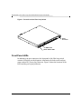
HP P4459A 8-Port Fibre Loop Switch Installation & Operation Guide HP Part Number 5971-0861 Printed in February 2001 Notice The information contained in this document is subject to change without notice. Hewlett-Packard makes no warranty of any kind with regard to this material, including, but not limited to, the implied warranties of merchantability and fitness for a particular purpose. Hewlett-Packard shall not be liable for errors contained herein or for incidental or consequential damages in connection with the furnishing, performance, or use of this material. Hewlett-Packard assumes no responsibility for the use or reliability of its software on equipment that is not furnished by Hewlett-Packard. This document contains proprietary information that is protected by copyright. All rights are reserved. No part of this document may be photocopied, reproduced, or translated to another language without the prior written consent of Hewlett-Packard Company. Hewlett-Packard Company Network Server Division Technical Communications MS 45SLE 10955 Tantau Avenue Cupertino, CA 95014 USA © Copyright 2001, Hewlett-Packard Company. Audience Assumptions This Installation and Configuration Guide is for the person who installs, administers, and troubleshoots LAN servers. Hewlett-Packard Company assumes you are qualified in the servicing of computer equipment and trained in recognizing hazards in products with hazardous energy levels. HP P4459A 8-Port Fibre Loop Switch Installation & Operation Guide Safety Instructions The following sections describe the symbols used on the fibre loop switch and within this guide and also provides safety information about the product: • Symbols Used on Equipment • Symbols in Text • Grounding Requirements Symbols Used on Equipment The following table describes the symbols that are used on the fibre loop switch. Any surface of area of the equipment marked with these symbols indicates the presence of electrical shock hazards. Enclosed area contains no operator serviceable parts. Warning: To reduce risk of injury from electrical shock hazards, do no open this enclosure. This product is a safety Class I product which has a protective earthing terminal. There must be an uninterrupted safety earth ground from the main power source to the product’s input wiring terminal, power cord(s), or supplied power cord set(s). Whenever it is likely that the protection has been impaired, disconnect the power cord(s) until the ground has been restored. APPARATEN SKALL ANSLUTAS TILL JORDAT NÄTTUTAG. iii HP P4459A 8-Port Fibre Loop Switch Installation & Operation Guide Symbols in Text The following symbols are used in the following formats to highlight special messages throughout this guide: Note: This format is used to highlight information of importance or special interest. Caution: This format is used to highlight information that will help you prevent equipment failure or loss of data. Warning: This format is used to highlight material involving possibility of injury or equipment damage. Danger: This format is used to alert you that you can incur an electrical shock by mishandling equipment. This product is a safety Class I product which has a protective earthing terminal. There must be an uninterrupted safety earth ground from the main power source to the product’s input wiring terminal, power cord(s), or supplied power cord set(s). Whenever it is likely that the protection has been impaired, disconnect the power cord(s) until the ground has been restored. APPARATEN SKALL ANSLUTAS TILL JORDAT NÄTTUTAG. iv Contents Contents ..........................................................................................................................v Preface...........................................................................................................................vii Related Publications .............................................................................................. vii Related Web Sites ................................................................................................ viii Chapter 1: Introducing the HP P4459A 8-Port Fibre Loop Switch ............................1 Fibre Loop Switch Features ....................................................................................1 GBIC Ports .....................................................................................................1 Front Panel LEDs ...........................................................................................2 Switching Operation ................................................................................................4 Fibre Channel Arbitration in the Fibre Loop Switch .......................................5 Fibre Loop Switch Initialization ......................................................................6 Chapter 2: Installing the Fibre Loop Switch ................................................................9 Unpacking the Fibre Loop Switch ............................................................................9 Installing and Removing GBICs in the Fibre Loop Switch .....................................10 Installing a GBIC ..........................................................................................10 Removing a GBIC ........................................................................................11 Rack Mounting the Fibre Loop Switch ...................................................................12 Rack Installation ...........................................................................................12 Powering up a System ..........................................................................................29 Cabling for the Fibre Loop Switch .........................................................................29 Chapter 3: Fibre Loop Switch Troubleshooting .......................................................31 General Maintenance Considerations ...................................................................31 Troubleshooting the Switch ...................................................................................32 Reading the LED Indicators .........................................................................32 Reset Button ..........................................................................................................34 Connections ..........................................................................................................34 Fibre Channel Cables ..................................................................................35 Temperature Control .............................................................................................35 Fans .............................................................................................................35 Filler Panel ...................................................................................................35 HP P4459A 8-Port Fibre Loop Switch Installation & Operation Guide Appendix A: Fibre Loop Switch Functional Specifications ......................................37 Switching ...............................................................................................................37 Physical Specifications ..........................................................................................37 Environmental Specifications ................................................................................37 Electrical Specifications .........................................................................................38 LED Specifications ................................................................................................38 Fibre Channel Communications ............................................................................38 Regulatory Certification .........................................................................................38 Appendix B: Regulatory Information ..........................................................................41 Regulatory Notices ................................................................................................41 Electromagnetic Compliance .......................................................................41 Regulatory Notices - Product Safety ............................................................46 Appendix C: Warranty and Support ............................................................................49 Hardware Accessories Limited Warranty ..............................................................49 Hewlett-Packard Hardware Accessories ......................................................49 Third-Party Hardware Products ...................................................................50 HP Repair and Telephone Support .......................................................................50 U.S. and Canada .........................................................................................50 Other Countries ............................................................................................50 World Wide Web ...................................................................................................51 Glossary .........................................................................................................................53 vi Preface The fibre loop switch provides an affordable entry-level SAN switch with multiple connectivity options. This guide provides information about the features and capabilities of the fibre loop switch, and how to install it. Related Publications The following publications provide information regarding Storage Area Networks (SANs) and the Fibre Channel protocol. Building Storage Networks, Farley, Marc, Osborne/McGraw-Hill, 2000. ISBN 0-07-212-050-9. Fibre Channel Arbitrated Loop, Kembel, Robert W., Tucson, Arizona: Connectivity Solutions, a division of Northwest Learning Associates, Inc., 1996. To order, call 1-520-881-0877 in the USA. Fibre Channel - Gigabit Communications and I/O For Computer Networks, Benner, Alan F., McGraw-Hill, 1996. Fibre Channel, Volume 1: the Basics, Jan Dedek and Gary Stephens, ANCOT Corporation, 115 Constitution Drive, Menlo Park, CA 94025, 1997. The Simple Book, An Introduction to Management of TCP/IP-based Internets, Marshall T. Rose, Prentice Hall, 1992. What Is Fibre Channel? Jan Dedek and Gary Stephens, ANCOT Corporation, 115 Constitution Drive, Menlo Park, CA 94025, November 1996. vii HP P4459A 8-Port Fibre Loop Switch Installation & Operation Guide Related Web Sites These web sites, among others, provide significant information regarding SANs and the Fibre Channel protocol. Table 1: viii Related Websites Site URL ANSI http://www.ansi.org/docs/home.html Fibre Channel Industry Association http://www.fibrechannel.com/ Storage Network Industry Association http://www.snia.org/ Chapter 1 Introducing the HP P4459A 8-Port Fibre Loop Switch The following sections of this chapter provide an overview of the features and functions of the fibre loop switch: • Fibre Loop Switch Features • Switching Operation Fibre Loop Switch Features The fibre loop switch features an integral 12Gb/sec. engine that enables full duplex, concurrent switching on all ports. Additional features of the fibre loop switch are described in the following sections: • GBIC Ports • Front Panel LEDs GBIC Ports The fibre loop switch is designed for maximum flexibility. It contains eight GBIC ports that can be configured to support copper, short-wave multimode fiber, and long-wave single mode fiber media connections. Because each of these media options provide different price/performance characteristics, you can mix and match GBICs to meet the needs of your storage network now, and add or exchange GBICs in the future as your network changes. 1 HP P4459A 8-Port Fibre Loop Switch Installation & Operation Guide Figure 1: Front View of the Fibre Loop Switch Power Connector GBIC Ports Switch Status LEDs Front Panel LEDs In addition to the port connectors, the front panel of the fibre loop switch contains LEDs that provide diagnostic information for both switch and port status, and an IEC power plug connector. Figure 2 shows the locations of the LEDs and the power plug connector. 2 Introducing the HP P4459A 8-Port Fibre Loop Switch Figure 2: Fibre Loop Switch front panel Power Plug Connector Switch Status LEDs Port Status LEDs Table 1 describes the operation of the switch LEDs and Table 2 describes the operation of the port LEDs on the front panel of the fibre loop switch. Table 1: Fibre Loop Switch LEDs Name Color Function fault Amber Indicates that the switch is running a self-test during start-up, or a failure occurred. power Green Indicates that power is on to the switch. Table 2: Port LEDs Name Color Function Link Green Indicates that a good physical link has been established. Fault Amber Indicates that faulty data is being received on the port. 3 HP P4459A 8-Port Fibre Loop Switch Installation & Operation Guide Switching Operation The fibre loop switch implements the Fibre Channel Arbitrated Loop protocol. It provides concurrent connections to the storage area network (SAN) without changing the FC-AL interface, which most SAN end-node devices normally communicate. The SAN operation changes dramatically when comparing a switch with a hub environment. The normal operation, as seen by a single end-node device, does not change, other than a rapid acceleration of responses in a switch environment. Figure 3 illustrates how the fibre loop switch alters the response speed without changing the nature of the responses seen by a participating node. Figure 3: Switching Using Fibre Channel Protocol The fibre loop switch maintains signal and data integrity by re-timing and re-amplifying the signal at each port. The data-path routing, however, is significantly different in the switch than with a hub. As shown on the top of Figure 3, a Fibre Channel network has a physical loop structure. All traffic must go through all nodes. Since the physical media is shared by all nodes, the bandwidth must be partitioned between any nodes that 4 Introducing the HP P4459A 8-Port Fibre Loop Switch wish to communicate. The addition of a hub, as shown in the center of the same figure, merely allows the cables from each node to go to a centralized location, such as a wiring closet where the hub is located. The media and bandwidth on that port are shared. The fibre loop switch has been designed with a non-blocking switch backplane; there is enough switch matrix bandwidth available to support simultaneous conversations between many nodes. The fibre loop switch helps reduce the time arbitration and loop initialization required in an active FC network. The fibre loop switch also supports an initialization agent called P4459A Name Server. These features are explained in the following sections: • Fibre Channel Arbitration in the Fibre Loop Switch • Fibre Loop Switch Initialization Fibre Channel Arbitration in the Fibre Loop Switch Normal Fibre Channel data traffic operation is constrained by loop tenancies. A loop tenancy is the time required for a complete data transfer. An FC node wanting to send data starts a loop tenancy by arbitrating for ownership of the loop. Upon winning arbitration, the device wanting to send data opens a communication channel to its intended destination. When the destination device responds that it has available buffer space, the sender sends data until it is finished. After the data transfer is complete, the sender closes the loop tenancy. An example: node C wants to send data to node A. The first step is that node C issues an arbitrate message. In a physical or hub-based Fibre Channel network topology, the arbitrate message has to circulate through nodes D, A, and B. Any of those nodes are capable of replacing C’s arbitrate message with its own higher-priority message, resulting in node C losing arbitration. Thus, any of the other nodes wanting to communicate interfere even though neither node A or C are involved with their activity. In the switch implementation, however, node C always wins arbitration. The only issue is whether node A is already active with a third node. If it is, node C has to wait, but the wait is only for as long as node A remains active. Three different scenarios are explained below: 5 HP P4459A 8-Port Fibre Loop Switch Installation & Operation Guide • If node A is free, node C’s data is forwarded directly to node A without interference. That is, the messages do not circulate through each device on the loop and so latency savings on this transaction are also gained. Note that all transactions are directed between the two communicating nodes. No traffic ever circulates the entire network as it would in a loop topology. • If node A is busy with another loop tenancy, the open message from node C is held until that loop tenancy is completed. Holding the open message until node A is free sounds extreme until one considers the latency around a normal loop operation with a high number of nodes. The time just for one open message to circulate around a large loop (greater than 60 nodes) and get back buffer credit is actually greater than the completion of an entire loop tenancy transferring a single maximum frame across the switch. The relative time difference is on the order of a magnitude (tens of microseconds vs. tens of milliseconds). • If A is busy and B, C, and D all simultaneously want to send data to A, a first-come, first-serve algorithm is enforced. This enforcement is realized due to the prioritized queueing of open messages at the destination. If the queue is greater than a programmable value, the switch responds with a close message to all subsequent open requests from other nodes. Fibre Loop Switch Initialization The initialization behavior of the fibre loop switch is encompassed within an intelligent agent referred to as P4459A Name Server. P4459A Name Server virtualizes the entire initialization process and eliminates the lengthy login procedure found on other switches. In a hub-based Fibre Channel network, any device generates Loop Initialization Protocol (LIP) messages to notify the other devices on the loop that initialization needs to occur. During the LIP process, each port in turn receives the LIP sequence and retransmits the LIP. This process continues until the LIP sequence returns to the initiating port. Since port addresses are assigned during the LIP process, no “real” work is performed on the loop while it is underway. Therefore, it is wise to have a measure of visibility and control over LIP generation. This is the advantage of P4459A Name Server. It limits the effects of a LIP on other devices in the network. Generally, a new node requires some period of time to become ready to participate on the network. The switch does nothing until the end node signals 6 Introducing the HP P4459A 8-Port Fibre Loop Switch that it is ready to participate by sending a LIP. Obviously, this interrupts any traffic in progress on that switch port, or on another switch port that is involved in a connection with a device on that switch port. However, it need not disrupt communications on any other switch port. Upon receiving a LIP, the switch conducts a series of passive tests on the new node, to verify that it is wellbehaved. 7 HP P4459A 8-Port Fibre Loop Switch Installation & Operation Guide 8 Chapter 2 Installing the Fibre Loop Switch The following sections of this chapter provide detailed instructions for installing a fibre loop switch: • Unpacking the Fibre Loop Switch • Installing and Removing GBICs in the Fibre Loop Switch • Rack Mounting the Fibre Loop Switch • Powering up a System • Cabling for the Fibre Loop Switch Note: Only trained personnel should install a loop switch. Please read all instructions fully before performing the installation. Unpacking the Fibre Loop Switch The fibre loop switch comes packed in a single, integrated shipping box. Retain the box to reship the switch if necessary. Included are the following items: • A fibre loop switch • This HP P4459A 8-Port Fibre Loop Switch Installation & Operation Guide • Two power cords • Two HSSDC copper GBICs • An HSSDC cable • A rack mount kit If any parts are missing, contact your sales or service representative. 9 HP P4459A 8-Port Fibre Loop Switch Installation & Operation Guide Installing and Removing GBICs in the Fibre Loop Switch Each port that you plan on using on the fibre loop switch must be configured with an HP-supported GBIC to provide media connectivity. Depending on the GBIC installed, connectivity options include copper and short-wave multi-mode fiber. Because each switch port can be configured with any GBIC, you can configure your switch for a variety of different media options to support your fibre channel architecture. Note: GBICs are hot-pluggable. This means that they can be installed and removed during operation, while the switch is running. The following sections describe: • Installing a GBIC • Removing a GBIC Installing a GBIC The following procedure describes how to install a GBIC into a switch port. Caution: GBICs are sensitive to static electricity. Static discharge from your clothing or other fixtures around you can cause damage. To prevent damage to the GBIC, wear a wrist strap or discharge leash to free yourself of static before touching it. 1. 2. 10 Holding it by its edges, remove the GBIC you are installing from its antistatic bag. Orient the GBIC in relation to the port you are installing it in so that the label side (or arrow) is on top. If your GBIC doesn’t have a label or an arrow to help you orient it, examine the D connector on it. The wider side of the D-connector should be on top. Figure 4 shows the orientation for installing a GBIC into a switch port. Installing the Fibre Loop Switch Figure 4: GBIC Orientation D-connector Guide tab Key Guide tab 3. Slide the GBIC through the port door and plug it into the 20-pin connector (not visible) on the host circuit board until it is firmly seated. If the GBIC does not install easily into the port, do not force it. Instead, try removing it and inverting the GBIC’s orientation. Warning: Do not look directly for the GBIC laser source. Laser beams can be harmful to your eyes. 4. 5. If you are not going to install cabling immediately, leave the supplied protective plug in place. The protective plug is used to shield the laser from view and to protect the optical components from dust. Repeat steps 1 through 4 for all GBICs that you want to install. Removing a GBIC The following procedure describes how to remove a GBIC: 1. Remove any cables attached to the GBIC. Stressing the cable during GBIC removal might break it. 11 HP P4459A 8-Port Fibre Loop Switch Installation & Operation Guide 2. Squeeze the latch levers (on the GBIC) together and pull the GBIC straight out. Note: GBIC latching mechanisms vary by manufacturer. Rack Mounting the Fibre Loop Switch The following sections provide information and procedures on how to rack mount the fibre loop switch. Warning: Reduce your risk of electric shock or damage to equipment by following these precautions: • Do not disable the power cord grounding plug. The grounding plug is an important safety feature. • Plug the power cord into an easily accessible, grounded electrical outlet. Because there is no power switch, you can turn power on and off by plugging in and disconnecting the power cord. • Disconnect the power from the unit by unplugging the power cord from either the electrical outlet or from the detachable plug on the unit. Rack Installation The fibre loop switch is designed to mount into a standard 19-inch rack up to 36 inches deep. Refer to the instructions included in the rack mount kit before attempting to mount the fibre loop switch. Only trained personnel should install the rack mount kit. Please read all instructions before installing the rails and sleeves. Caution: The air vents along the side and back panel of the fibre loop switch must not be blocked when installed. The operating temperature must be kept between 10 and 40 degrees Celsius (between 50 and 104 degrees Fahrenheit). 12 Installing the Fibre Loop Switch Rack Installation Basics Caution: Do the following to prevent the rack enclosure from tipping over. Failure to take these precautions could result in serious injury and equipment damage. • Extend the anti-tip foot, or verify that the anti-tip feature is installed. • Verify that the leveler feet are lowered. • Do NOT extend more than one piece of equipment at a time out from the front of the rack. Always keep the following safety and environmental issues in mind: • Maximum Recommended Ambient Temperature: The maximum recommended ambient temperature of the room is 35°C (95°F). • Elevated Operating Ambient Temperature: The ambient operating temperature within a closed or multi-unit rack assembly may exceed the room’s ambient temperature. Make sure that the temperature within the rack itself does not exceed 35°C (95°F). • Air Flow: As you mount equipment in the rack, make sure that you allow enough air flow for safe operation of the equipment. • Mechanical Loading: Uneven mechanical loading within the rack can cause hazardous conditions. Plan the placement of equipment in the rack to avoid this problem. • Circuit Overloading: Make sure that the total configuration of equipment in the rack does not overload the supply circuit. To verify this, check the nameplate ratings on all equipment. Consider the effect of circuit overloading on over-current protection and supply wiring. • Reliable Earthing (Grounding): Maintain reliable earthing (grounding) of rack-mounted equipment. Give particular attention to supply connections that are not direct connections to the branch circuit (the use of power strips, for example). • Installation Order: Begin installing components at the bottom of the rack. Rack Installation Overview The instructions in this guide are specifically for Hewlett-Packard rack enclosure product numbers J1464A, J1466A, J1487B, J1488A, J1500A, J1501A, and J1502A. For information about other rack installations, see the rack-mount kit 13 HP P4459A 8-Port Fibre Loop Switch Installation & Operation Guide instructions that come with your rack or HP NetServer, or refer to the following web site: http://www.hp.com/racksolutions Note: The installation instructions that follow use “left” and “right” to refer to rack columns as viewed from the rear of the rack. Figure 5 and Figure 6 present a visual summary of the switch’s rack-mounting hardware. Figure 5: Mounting in HP Systems Racks Left Front Rack Column Right Front Rack Column Sleeves Right Rear Rack Column Switch Left Rear Rack Column 14 Rails Installing the Fibre Loop Switch Figure 6: Mounting in HP Rack System/E and HP Rack System/U Racks Right Front Rack Column Left Front Rack Column "L" Spacer "R" Spacer Sleeves Right Rear Rack Column Switch Left Rear Rack Column Rails Tools Required To install the switch in an HP rack, you need a T25 Torx driver and a #1 Phillipshead screwdriver. HP Rack Mounting Installation Steps Installing the fibre loop switch into an HP rack requires the following general steps: • Step 1: Preparation • Step 2: Mark the Rack Column Holes • Step 3: Place the Barrel Nuts on the Rack Columns • Also install the “L” and “R” spacers on the front columns of HP Rack System/E and HP Rack System/U racks only. 15 HP P4459A 8-Port Fibre Loop Switch Installation & Operation Guide • Step 4: Attach the Sleeves to the Front Rack Columns • Step 5: Attach the Switch Rails to the Switch Chassis • Step 6: Install the Switch • Step 7: Complete the Installation Step 1: Preparation Before you install the switch into an HP rack, refer to the rack documentation as you extend the anti-tip foot or ensure that the anti-tip feature is installed. Lower the leveler feet. Caution: Do the following to prevent the rack enclosure from tipping over. Failure to take these precautions could result in serious injury and equipment damage. • Extend the anti-tip foot, or verify that the anti-tip feature is installed. • Verify that the leveler feet are lowered. • Do NOT extend more than one piece of equipment at a time out from the front of the rack. Use the original ordering information to locate where each component goes in the rack. If the original ordering information is not available, use the HP Rack Assistant software to determine where to mount the switch in the rack. Use tape or a marker pen to mark the bottom of the single EIA unit required by the switch. For EIA unit boundaries, refer to Figure 7 and Figure 8. 16 Installing the Fibre Loop Switch Figure 7: Marking Holes and Attaching Barrel Nuts on HP Systems Racks Right Rear Rack Column EIA Unit Barrel Nuts Left Rear Rack Column 17 HP P4459A 8-Port Fibre Loop Switch Installation & Operation Guide Figure 8: Marking Holes and Attaching Barrel Nuts on HP Rack System/E and HP Rack System/U Racks Right Rear Rack Column EIA Unit Barrel Nuts Left Rear Rack Column Step 2: Mark the Rack Column Holes Use tape or a marking pen to mark the screw holes where you will install the barrel nuts: • On each rear rack column, mark the top and bottom holes of the EIA unit on the inside of the column, as shown in Figure 7 and Figure 8. • On each front rack column, mark the hole on the middle of the EIA unit on the inside of the column. Step 3: Place the Barrel Nuts on the Rack Columns 1. Identify the six barrel nuts by referring to Figure 7 and Figure 8. 18 Installing the Fibre Loop Switch 2. Place two barrel nuts on each of the rear rack columns at the holes you marked, as shown in Figure 7 and Figure 8. Note: Install the barrel nuts with the threaded nut part of the barrel nut on the inside face of the rack column. 3. For HP Systems racks only, attach one barrel nut to each of the front rack columns at the holes you marked. For HP Rack System/E and HP Rack System/U racks do NOT attach barrel nuts to the front columns. Attach Spacers to HP Rack System/E and HP Rack System/U Racks Use the spacers (shown in Figure 9) on HP Rack System/E and HP Rack System/ U Racks only (product numbers J1500A, J1501A, J1502A, J1464A, and J1466A). Do NOT use them for HP Systems racks (product numbers J1487B and J1488A). The spacers are marked “L” and “R” because they differ. Install them inside the front rack columns. Left and right front rack columns in the instructions below are as viewed from the rear of the rack. • Put the “R” spacer on the left front rack column, as shown in Figure 9. • Put the “L” spacer on the right front rack column, as shown in Figure 9. Note: The three holes in the spacer correspond to the three holes in the EIA unit. Align the middle hole in the spacer with the hole you marked on the front rack column. 19 HP P4459A 8-Port Fibre Loop Switch Installation & Operation Guide Figure 9: Installing Spacers on HP Rack System/E and HP Rack System/U Racks Left Front Right Front Rack Column Rack Column "L" Spacer Right Rear Rack Column "R" Spacer Left Rear Rack Column Step 4: Attach the Sleeves to the Front Rack Columns When the installation is complete, each rack rail will consist of two parts, as shown in Figure 10 and Figure 11: • A switch rail, which is mounted on the switch chassis and is later attached to the rear rack column • A sleeve, which is mounted on the front rack column and which receives the switch rail Attach the sleeves to the insides of the front rack columns, as follows: 1. 20 Identify the two sleeves, as shown in Figure 10. Installing the Fibre Loop Switch Figure 10: Identifying Switch Rails and Sleeves (Oriented for HP Racks) Switch Rail Sleeve Sleeve Flange Switch Rail Flange 2. Identify the six Torx screws. 21 HP P4459A 8-Port Fibre Loop Switch Installation & Operation Guide Figure 11: Attaching Sleeves to an HP Systems Rack Right Front Rack Column Rack Nut Rack Nut Sleeve Sleeve Sleeve Flanges Left Front Rack Column 22 Installing the Fibre Loop Switch Figure 12: Attaching Sleeves to HP Rack System/E and HP Rack System/U Racks Right Front Rack Column Spacers on Inside of Rack Columns Right Sleeve Sleeve Flanges Left Sleeve Left Front Rack Column 3. Position one sleeve on the inside of the rack front column with the sleeve’s flange side toward the rack column, as shown in Figure 11 or Figure 12. Align the hole in the front end of the sleeve with one of the following holes: • The rack column hole with the barrel nut on HP Systems rack. 4. 5. • The middle hole of the spacer on HP Rack System/E and HP Rack System/U racks. Hold the sleeve firmly to the rack column, and insert one Torx screw through the sleeve and into the spacer or barrel nut, as shown in Figure 11 or Figure 12. Finger tighten the screw. Attach the other sleeve to the other front rack column in the same way. 23 HP P4459A 8-Port Fibre Loop Switch Installation & Operation Guide Step 5: Attach the Switch Rails to the Switch Chassis 1. Remove the two side screws (one on each side of the switch chassis) that retain the cover, as shown in Figure 13. You will not use these short screws in the rest of this assembly. Figure 13: Securing the Switch Rails to the Switch Insert #1 Phillips-head screw provided Remove short screw here, and insert #1 Switch Rails Phillips-head screw provided Switch Insert #1 Phillipshead screw provided Rear Panel Switch Rail Flanges Remove short screw here, and insert #1 Phillips-head screw provided 2. Attach one of the switch rails to the side of the switch chassis with two of the #1 Phillips-head screws provided, as follows: • Orient one switch rail against the switch chassis as shown in Figure 13. The flange on the switch rail is on the outer side of the switch rail and near the rear panel. • Align the holes in the switch rail with the screw holes in the switch chassis as indicated in Figure 13. 3. 24 • Insert the two #1 Phillips-head screws through the switch rail and into the switch chassis as shown in Figure 13. Tighten the screws. Attach the second switch rail to the other side of the switch in the same way. Installing the Fibre Loop Switch Step 6: Install the switch Have the remaining four Torx screws available as you install the switch. 1. 2. 3. 4. Pick up the switch chassis (with the switch rails installed) with the open switch rail ends away from you. Carry it to the rear of the rack. Carefully align the switch rail ends with the open rack sleeves, and gently ease the chassis into the rack sleeves like a drawer, as shown in Figure 14 and Figure 15. Align the two holes on one switch rail with the holes with the barrel nuts on the rear rack column, as shown in Figure 14 and Figure 15. Attach that switch rail to the rear rack column with two Torx screws. The screws go through the flange on the switch rail first, and then into the barrel nut. Finger tighten the screws. 25 HP P4459A 8-Port Fibre Loop Switch Installation & Operation Guide Figure 14: Installing the Switch into an HP Systems Rack Right Front Rack Column Sleeves Right Rear Rack Column Switch Left Front Rack Column Left Rear Rack Column 26 Switch Rail Flanges Installing the Fibre Loop Switch Figure 15: Installing the Switch into an HP Rack System/E or HP Rack System/U Rack Right Front Rack Column Sleeves Right Rear Rack Column Switch Left Front Rack Column Left Rear Rack Column 5. 6. Switch Rail Flanges Attach the other switch rail to the other rear rack column in the same way. Use the T25 driver in a couple of passes to tighten all six screws that you installed in the rack columns. Step 7: Complete the Installation 1. Connect the appropriate AC power cord to the switch. 27 HP P4459A 8-Port Fibre Loop Switch Installation & Operation Guide Plugging in the other end of the power cord will apply power to the switch. You can do either of the following: • Connect the other end of the power cord to the power receptacle on the rack, which means you will hot-plug devices to the switch. 2. • Wait to plug in the other end of the power cord, so that you can connect devices to the switch before you power it. If you purchased a filler panel separately, install the filler panel on the front of the rack by pressing it into place, as shown in Figure 16. Figure 16: Installing the Filler Panel (Shown for HP Rack System/E and HP Rack System/U Racks) Right Front Rack Column Filler Panel Right Rear Rack Column Switch Left Front Rack Column Left Rear Rack Column 3. 28 Retract the anti-tip foot, if desired. Installing the Fibre Loop Switch Powering up a System When bringing up an FC-AL system, first make all the connections with the equipment powered down, then turn on the fibre loop switch before turning on any other operating component. The fibre loop switch does not have an On/Off switch. For convenience and safety, connect the power cord to a grounded AC outlet near the rack or desk so it is easily accessible. Ensure that the appropriate power plug is available for the installation area. 1. Plug the power cord into the loop switch’s power receptacle, then plug the opposite end into a power receptacle. On power-up or when you press the reset button, the switch runs several power-on self tests during start-up. The LEDs display changing patterns. See Table 1 on page 3 to interpret the LEDs as the switch comes up. 2. 3. 4. Power on a host and I/O units. Verify the presence of the I/O from units on the host. Start the server application. Cabling for the Fibre Loop Switch The fibre loop switch supports connection to multiple media formats. Note: The following rules should be observed regarding cabling: • • • • • Support and route the cables to prevent damage from sharp edges or from being crushed by nearby equipment. It is important to route copper cables so that they do not introduce noise. Don’t lay them over transformers or alongside power cables for any distance. Provide support for installed cables, and do not allow them to have a bend radius of less than 3 inches (76 mm). This is particularly important with fiber optic cables as a sharp bend can decrease their performance even if they are not physically damaged. When connecting fiber optic cables together with a barrel connector, make sure that both fibers are the same mode and diameter. Laser types at each end of a link must match. Cabling requirements for the fibre loop switch depend on the GBICs installed. Depending on the GBIC, it can support multi-mode fiber, single mode fiber, or 29 HP P4459A 8-Port Fibre Loop Switch Installation & Operation Guide copper cabling. Table 3 provides the specifications for optical cable support and Table 4 provides the specifications for copper cable support. Table 3: Optical cable requirements for the Fibre Loop Switch Cable Spec Multi Mode Fiber Single Mode Fiber Distance in Meters 2m–300m 2m–500m 2m–10Km Fiber Core Size 62.5 µm (TIA standard for premise wiring for US and international use.) 50 µm (Not standard for premise wiring use. Proprietary point-topoint cabling use only.) 9 µm GBIC Type Shortwave laser Shortwave laser Longwave laser Wave Length 780–850 nm 780–850 nm 1310 nm Table 4: Copper cable requirements for the Fibre Loop Switch 30 Cable Spec Value Signal Level FC Intra-Cabinet Standard Connector Type DB-9 or HSSDC Distance in Meters >10–33 m (equalized cable) 0–10 m (unequalized cable) Chapter 3 Fibre Loop Switch Troubleshooting The following sections of this chapter provide information to help you troubleshoot problems with your fibre loop switch: • General Maintenance Considerations • Troubleshooting the Switch • Reset Button • Connections • Temperature Control General Maintenance Considerations To protect the switch for longer use, we recommend that you: • Periodically vacuum the external surfaces of the switch to remove dust. • Do not drop fiber optic cable connectors onto hard surfaces. This can cause internal glass fractures and intermittent signals. • Keep unused cable ends covered to prevent contamination from obscuring or attenuating the light signals • Keep unused GBIC connections covered to prevent contamination from obscuring or attenuating the light signals. • Always follow the GBIC manufacturer’s recommended procedures for cleaning the GBIC. This is especially true of the type of solvent used for cleaning optical surfaces. 31 HP P4459A 8-Port Fibre Loop Switch Installation & Operation Guide • Never insert foreign objects into optical transmit and receive ports. • Do not bend fiber cable to less than a three-inch bend radius. Troubleshooting the Switch If there is a problem accessing a device connected to the fibre loop switch, the source of the problem can be with the device, the switch, the host, or any of the connections between the host and device. Follow the steps outlined below to investigate the problem. A description of possible symptoms and probable causes follows: 1. 2. 3. 4. 5. Check the power LED. If it is off, the unit may not be plugged into main power. Inspect the switch fault LED indicators for apparent problems. If the fault LED goes on, the switch may be faulty or the temperature may be out of limits. Inspect the cabling between the switch and attached Fibre Channel devices. Check for loose, dirty, broken, or bent cabling and connectors. If GBICs are in use, check that they are properly inserted and that their cables are properly seated. Check the port status LEDs. Reading the LED Indicators The LED indicators provide information about the status of the switch. These should be used as the first stage in troubleshooting. The various LEDs are interpreted by the following tables: 32 • Table 5 interprets the behavior that the Power, Fault and Initialization LEDs exhibit. • Table 6 gives a generic description of the Port LEDs. Fibre Loop Switch Troubleshooting Table 5: Reading The Power, Fault, and Initialization LEDs Label LED Color/ Pattern Interpretation Possible Causes Power Green/ON The unit is connected to an AC power source and the internal power supply is functioning. This is the normal state when powered on. OFF No power within the switch. -The line has no voltage. -The switch is disconnected or the power cable is bad. -The switch is faulty. Fault Amber/ON -Switch is running a self-test. - This is the normal self-test state. -If the test fails, the switch may be faulty. -If the light remains on after 15 seconds, the switch failed the selftest or an environmental fault has occurred. OFF Self-test completed with no fault found. Normal running state. Table 6: Reading The Port LEDs Link (Green Fault (Amber) Interpretation Possible Causes OFF OFF No signal Either: a. no GBIC has been installed or b. no cable with a valid signal has been attached since the GBIC was installed. ON OFF Good Signal Normal state for a valid port connection OFF ON Port is bypassed Bad signal or no signal. 33 HP P4459A 8-Port Fibre Loop Switch Installation & Operation Guide Link (Green Fault (Amber) Interpretation Possible Causes ON ON Switch is resetting. Not a valid state at any other time. Power up or a reset. Reset Button Use the reset button with caution. The Reset button on the front panel of the switch resets the internal control microprocessor of the switch. Sometimes a reset clears a problem that appears to be the result of an unidentified error. Pushing the Reset button interrupts all traffic and forces re-initialization of the loop. The switch bypasses all ports and goes through normal power-on operations. Then the switch reconnects the network by initializing all the ports connected to active devices. Resetting the switch disrupts the network. This may affect performance, but does not corrupt data on disk drives attached to the switch. It does, however, erase any statistics and other management data that have been collected. Connections The following subsections describe the handling of GBICs and Fibre Channel cables. Caution: GBICs are sensitive to static electricity. Static discharge from your clothing or other fixtures around you can cause damage. To prevent damage to the GBIC, wear a wrist strap or discharge leash to free yourself of static before touching it. 34 • Leave the device in its antistatic bag until ready to install it. • Hold the GBIC by its edges and handle it carefully. • Always follow the GBIC manufacturer’s recommended procedures for cleaning the GBIC. This is especially true of the type of solvent used for cleaning optical surfaces. • Do not install any GBIC that appears physically damaged. This may result in permanent damage to the switch. Fibre Loop Switch Troubleshooting • Keep unused GBIC connectors covered with the plugs that are shipped with them to prevent contamination from obscuring or attenuating the light signals. Fibre Channel Cables The fibre loop switch uses Fibre Channel cables to communicate with cascaded and end-node devices. Loose or broken cables can cause a number of problems. Inspect the cabling between the switch and attached Fibre Channel devices. Check for loose, dirty, broken, or bent cabling and connectors. 1. 2. 3. Inspect the switch fault LED indicators for apparent problems. Check that the GBICs are properly inserted. Check the port status LEDs. Temperature Control As in the case of almost all commercial electronics, the fibre loop switch is designed to work in a normal room temperature environment, which is between 10º and 40º C. In order to maintain adequate cooling, the fibre loop switch is equipped with fans and a filler panel. Fans Three fans provide forced-air cooling and operate in parallel. Caution: The air vents along the side and back panel of the fibre loop switch must not be blocked when installed. The operating temperature must be kept between 10 and 40 degrees Celsius (between 50 and 104 degrees Fahrenheit). Filler Panel The filler panel that came with the switch must be left in the back slot in order to direct the forced-air cooling. The GBIC slots have doors to serve the same purpose as the filler panel and they must remain closed if a GBIC is not installed. 35 HP P4459A 8-Port Fibre Loop Switch Installation & Operation Guide 36 Appendix A Fibre Loop Switch Functional Specifications Switching Switch Backplane Bandwidth..........12 Gigabits per second Switching Mode...............................Non-Blocking Port Speed........................................1.0625 Gigabits per second Communication Modes ...................Full or Half Duplex, Diplex Port-to-Port Latency ........................< 2 microseconds Physical Specifications Specifications that follow are without mounting hardware or GBICs. Height ..............................................1.66 in (42 mm) Width ...............................................17.3 in (439 mm) Depth ...............................................16.26 in (413 mm) Weight with Power Supply ..............10.681 lbs (4.85 Kg) Environmental Specifications Non-Operating Temperature .....................................−30º to +60º C Relative Humidity ...........................10% to 90% non-condensing Operating Temperature .....................................+10º to +40º C Relative Humidity ...........................20% to 80% non-condensing Acoustic Noise Emissions ...............<46 dBA 37 HP P4459A 8-Port Fibre Loop Switch Installation & Operation Guide Electrical Specifications AC Voltage ......................................100–240 VAC autosensing Frequency ........................................50 to 60 Hz Rated Input Current .........................1.5A — 0.7A LED Specifications Front Panel LED Indicators Power...............................................Green Fault.................................................Amber Init....................................................Green Port LED Indicators Link..................................................Green Fault.................................................Amber Fibre Channel Communications Media...............................................DB-9 Copper, HSSDC Copper, SW Optical Dual SC, GBIC Protocol and Standards ....................FC-AL, FC-AL-2, FC-PH, FC-PH-2, FC-PH-3, FC-PLDA, FCP Regulatory Certification Safety Compliance USA .................................................UL 1950, 1995 3rd Edition Canada .............................................CSA C22.2 No. 950-95, 3rd Edition European Union (EU) and Nordic .......................................EN 60950: 1992 A1/A2/A3/A4/A11 EMKO-TSE (74-SEC) 207/94 Other Countries: ..............................IEC 60950: A1/A2/A3/A4 EMC Compliance USA .................................................FCC Title 47 CFR, Part 15, SubpartB; 1998, Class A Canada .............................................ICES-003, Class A 38 Fibre Loop Switch Functional Specifications European Union (EU)......................EN 55022: 1994 +A1 +A2, Class A EN61000-3-2: 1995 EN61000-3-3: 1995 EN 55024: 1998 Japan ................................................VCCI V3: 1997, Class A JEIDA Guideline for the suppression of harmonics: 1993 Australia/New Zealand....................AS/NZS 3548/95, Class A Other Countries ...............................CISPR 22: 1997, CISPR24:1997 39 HP P4459A 8-Port Fibre Loop Switch Installation & Operation Guide 40 Appendix B Regulatory Information Regulatory Notices Electromagnetic Compliance Electromagnetic Compatibility (EMC) requirements have been established in many countries to regulate the radio frequency energy generated by Information Technology Equipment (ITE). This energy is generated during the normal and intended use of this equipment and so it is limited by country regulations to levels intended to minimize potential interference to other electrical equipment, including public safety services. Two levels of radio frequency energy are allowed according to the type or use of equipment. Class A levels have been established for use in commercial or business environments. Class B levels are lower than the Class A requirement and have been established for use in residential environments. Class B levels are also suitable when the environment includes electrically sensitive equipment. The fibre loop switch that you have purchased has been provided with compliance labels to indicate where it may be used with reasonable protection to the environment in which it is used. Additional statements are provided below as required by the requirements of international and domestic regulations. Wire connections to GBICs installed in this product must be made with shielded cables with metallic RFI/EMI connector hoods in order to maintain compliance with FCC rules and regulations. Note: Check the label on your product to determine the level of operation. 41 HP P4459A 8-Port Fibre Loop Switch Installation & Operation Guide Notice for United States Class A Equipment This equipment has been tested and found to comply with the limits for Class A digital devices, pursuant to Part 15 of the FCC (Federal Communications Commission Rules). These limits are designed to provide reasonable protection against harmful interference when the equipment is operated in a commercial environment. This equipment generates, uses, and can radiate radio frequency energy and, if not installed and used in accordance with the instructions manual, may cause harmful interference to radio communications. Operation of this equipment in a residential area is likely to cause harmful interference in which case the user is required to correct the interference at their own expense. Class A Accessories Installation and use of a Class A accessory creates a system that meets the requirements for industrial and commercial environments. If you are installing a Class A accessory in a system that has been labeled as a Class B product, the requirements and notice for Class A equipment shall be applied. Notice for Canada This Class A digital apparatus meets all requirements of the Canadian Interference-Causing Equipment Regulations. Cet appareil numérique de la Classe A respecte toutes les exigences du Règlement sur le matériel brouilleur du Canada. Notice for Japan For products labeled as Class A: This equipment is in the Class A category information technology equipment based on the rules of Voluntary Control Council For Interference by Information Technology Equipment (VCCI). When used in a residential area, radio interference may be caused. In this case, user may be required to take appropriate corrective actions. 42 Regulatory Information Notice for Korea Class A Warning Please note that this equipment has been approved for business purposes with regards to electromagnetic interference, if purchased in error for use in residential area, you may wish to exchange the equipment where you purchased it. Notice for Taiwan Class A Warning 43 HP P4459A 8-Port Fibre Loop Switch Installation & Operation Guide Notice for European Union Radio Frequency Emissions Warning for Accessories This product has been found to comply with CISPR 22 Class A EMC emission limits. Installation and use of a Class A accessory creates a system that meets the requirements for industrial and commercial environments. However, in a domestic environment, this product may cause radio interference, in which case the user may be required to take adequate measures. 44 Regulatory Information Declaration of Conformity (US and EU) DECLARATION OF CONFORMITY according to ISO/IEC Guide 22 and EN 45014 Manufacturer's/Supplier Name: Hewlett-Packard Company Manufacturer's/Supplier Address: 10955 Tantau Avenue Cupertino, Ca 95014 USA declares, that the product Product Name: Model Number(s): Product Options: HP 8-Port Fibre Loop Switch P4459A All conforms to the following Product Specifications: Safety: IEC 60950: 1991 +A1, A2, A3, A4/ EN 60950: 1992 + A1, A2, A3, A4, A11 GB4943-1995 EMC: EN 55022: 1998/CISPR 22:1997, ITE Radiated and Conducted Emissions CFR 47 Part 15, Subpart B, Unintentional Radiators, Radiated and Conducted Emissions EN 61000-3-2: 1995 +A1: 1998, Harmonic Current Emissions EN 61000-3-3: 1995, Voltage Fluctuation and Flicker EN55024: 1998/CISPR 24: 1997 EN 61000-4-2/IEC 61000-4-2: 1995, ESD EN 61000-4-3/IEC 61000-4-3: 1995, Radiated Immunity EN 61000-4-4/IEC 61000-4-4: 1995, Fast Transient/Burst EN 61000-4-5/IEC 61000-4-5: 1995, Surge EN 61000-4-6/IEC 61000-4-6: 1996, Conducted Immunity EN 61000-4-11/IEC 61000-4-11: 1994, Voltage Dips and Interruptions Supplementary Information: 1) The product was tested in a typical configuration. 2) The product complies with Part 15 of the FCC rules. Operation is subject to the following two conditions: This device may not cause harmful interference, and This device must accept any interference received, including interference that may cause undesired operation. The product herewith complies with the requirements of the following directives and carries the CE-marking accordingly: - EMC Directive 89/336/EEC including Ce Marking Directive 93/68/EEC - Low Voltage Directive 73/23/EEC Cupertino, March 1, 2001 North American Contact: Hewlett-Packard Company 3000 Hanover Street Palo Alto, CA 94304 650-857-1501 European Contact: Your local Hewlett-Packard Sales and Service Office or Hewlett-Packard GmbH Department ZQ/Standards Europe, Herrenberger Straße 130, D-7030 Böblingen, (FAX: + 49-7031-14-3143) Quality Management Services & Systems Phone ++613 9272 8355 45 HP P4459A 8-Port Fibre Loop Switch Installation & Operation Guide Regulatory Notices - Product Safety This product may be equipped with a Hewlett-Packard Optical GBIC containing a laser. In which case the GBIC is a Class 1 Laser Product per US/FDA/CDRH (21 CFR) and per IEC-825-1 (EN60825-1 and A11). Laser Safety– United States CAUTION This device contains a laser system and is classified as a "Class-1 Laser Product" under a U.S. Department of Health and Human Services (DHHS) Radiation Performance standard according to the Radiation Control for Health and Safety Act of 1968. To ensure proper use of this product, please read this instruction manual carefully and retain for future reference. Should the unit ever require maintenance, contact an authorized service location. WARNING Use of controls, adjustments or the performance procedures other than those specified herein may result in hazardous radiation exposure. To prevent direct exposure to laser beam, do not try to open the enclosure Laser Safety - Finland 46 • LASERTURVALLISUUS • LUOKAN 1 LASERLAITE • KLASS 1 LASER APPARAT Regulatory Information Laser Safety - Germany VORSICHT Diese Gerät enthält ein Laser-System und ist als "LASER PRODUKT DER KLASSE 1"klassifiziert. Für den richtigen Gebrauch dieses Modells die Bedienungsanleitung sorgfältig durchlesen und als Referenz aufbewahren. Falls Probleme mit diesem Modell aufreten, die nächste "authorisierte Services-Verrtetung" benachrichtigen. Um einen direkten Kontakt mit dem Laserstrahl zu vermeiden, soll das Gehäuse nicht geöffnet werden. VORSICHT Die Verwendung von anderen Steuerungen oder Einstellungen oder das Durchführen von anderen Vorgängen als in der Bedienungsanleitung beschrieben kann gefährliche Strahlenexpositionen zur Folge haben 47 HP P4459A 8-Port Fibre Loop Switch Installation & Operation Guide CLASS 1 LASER PRODUCT LASSER KLASSE 1 PRODUKT 48 This Fibre Loop Switch Unit is classified as a CLASS 1 LASER PRODUCT. Appendix C Warranty and Support The hardware warranty below applies to components purchased as accessories. If your component was factory installed as part of an HP Netserver model, refer to the HP Netserver Warranty and Service/Support Booklet for the warranty limitations, customer responsibilities, and other terms and conditions. Hardware Accessories Limited Warranty Hewlett-Packard Hardware Accessories An HP Netserver Hardware Accessory is an internal HP hardware product that is specifically designated for use with HP Netservers; is added on or integrated into an HP Netserver in order to provide higher performance, capacity, or increased capability; and is listed as a product in HP's Corporate Price List. Upon installation inside an HP Netserver, the HP Netserver Hardware Accessory carries a System-Matching Warranty. This warranty includes a one-year Return-to-HP warranty or the remainder of the warranty period for the original HP Netserver in which it is installed, whichever is longer. This accessory may be serviced through expedited part shipment. In this event, HP will prepay shipping charges, duty, and taxes; provide telephone assistance on replacement of the component; and pay shipping charges, duty, and taxes for any part that HP asks to be returned. HP warrants this HP Netserver Hardware Accessory against defects in material and workmanship, under normal use, for the period specified in the section titled HP Netserver Limited Warranty Coverage. The warranty commences on receipt of this product by Customer from HP or Reseller. If HP or Reseller receives 49 HP P4459A 8-Port Fibre Loop Switch Installation & Operation Guide notice of such defects during the warranty period, HP or Reseller will either, at its option, repair or replace products that prove to be defective. Should HP or Reseller be unable to repair or replace the hardware accessory within a reasonable amount of time, Customer's alternate remedy shall be a refund of the purchase price upon return of the hardware accessory product. HP products external to the system processor unit, such as external storage subsystems, printers, or other peripherals, are covered by the applicable warranty for those products. HP SureStore drives are considered external accessories and carry their own warranty. The customer may be required to run HP-supplied configuration and diagnostic programs before a replacement will be dispatched or an on-site visit is authorized. Third-Party Hardware Products HP does not warrant third-party hardware products. Third-party hardware products may be warranted in accordance with the third-party warranty statement accompanying the product. On-site visits caused by third-party hardware products—whether internal to the HP Netserver system processor unit (such as non-HP DIMMs) or external to the system processor unit (such as LAN cabling)—are subject to standard per-incident travel and labor charges. HP Repair and Telephone Support U.S. and Canada For hardware repair or telephone support in the U.S. and Canada contact HP Customer Support Center (Colorado) (970) 635-1000 (24-hours a day, 7-days a week). Other Countries Refer to the HP Netserver Warranty and Service/Support Booklet supplied with your HP Netserver system documentation for instructions on how to obtain HP repair and telephone support. 50 Warranty and Support World Wide Web On the World Wide Web go to: http://netserver.hp.com/netserver/ 51 HP P4459A 8-Port Fibre Loop Switch Installation & Operation Guide 52 Glossary This glossary contains terms and acronyms that may be found in this documentation. AL_PA Arbitrated Loop Physical Address. The low-order byte of a 3-byte Fibre Channel Source/Destination ID field that defines an address hierarchy. This is also called a Loop ID. See D_ID or S_ID. AL_PD A destination AL_PA. AL_PS A source AL_PA. ANSI American National Standards Institute, the organization that coordinates voluntary standards for programming languages, telecommunications, properties of disk and tape media, and more, in the United States. Arbitrated Loop A Fibre Channel standard defining a loop topology where up to 126 devices communicate with one another using an arbitrated access protocol. Arbitration The process of selecting one respondent from a collection of several candidates that request service concurrently. Area See Fibre Channel Address. 53 HP P4459A 8-Port Fibre Loop Switch Installation & Opeartion Guide Bandwidth The amount of data per second that can be transferred from one device to another. Bandwidth limits are set by a combination of speed of transfer, capacity of the pipe, number of pipes, and overhead of sending the data. It is possible to transmit one signal at the maximum specified bandwidth, or several different signals simultaneously on different channels, each of them using a portion of available bandwidth. BLS Basic Link Services (also known as Link Service). A Fibre Channel request/ response protocol common to all devices. The most universally implemented Basic Link Service is Abort Sequence (ABTS), used for error recovery. Broadcast A transmission sent to all N_Ports on a network. Bypassed port A port status that indicates a port is not enabled on a loop, even though the port is still physically connected to the network. A bypass can be automatic or manual. Channel A pathway between components in a computer system or between workstations in a network. Cluster A group of systems that work together as a single system to provide fast, uninterrupted service. It is a way to increase capacity and to add I/O bandwidth. Credit A numeric flow control value that establishes advance permission to send one or more frames. It is used for either end-to-end or buffer-to-buffer Class-2 frames. As long as a port has a credit of greater than 0, it is able to continue to send frames. Credit is granted by a port during the login process. Datagram Datagram refers to an unacknowledged Fibre Channel frame or frame sequence, borrowed from networking terminology. The Fibre Channel standards use it specifically to refer to the type of unacknowledged service defined by Class 3 delivery. Device See FC-AL Device. 54 Glossary D_ID Destination ID. A Fibre Channel Address of a frame defining the destination node for that frame. Diplex Communications In addition to full duplex communications between a pair of nodes, a node can receive from another node, while simultaneously transmitting to a third node independently. Domain See Fibre Channel Address. Duplex (full) Operation of a data communication link where transmissions are possible in both directions simultaneously. Duplex (half) Operation of a data communication link where transmissions are possible in both directions, but only in one direction at a time. ELS Extended Link Services support messaging protocol for discovery and dynamic address partitioning. EMC ElectroMagnetic Compatibility. Embedded Node Agent An in-band Node Agent conducts automatic discovery and display of SCSI and SES targets, SES enclosures. Enclosure The box, rack, or set of boxes containing one or more devices. It can provide power, cooling, and other support functions to the devices. E_Port Expansion Port. It specifies the interconnection and initialization for a Fibre Channel switch to create an inter-switch link. It is similar to an N_Port and an F_Port. Fabric Fibre Channel-defined interconnection methodology that handles routing in Fibre Channel networks. 55 HP P4459A 8-Port Fibre Loop Switch Installation & Opeartion Guide FC-0 The set of Fibre Channel standards that address media (optics, copper, connectors), and physical signalling over that media (signal rates and timing, signal quality, power, jitter, etc.). FC-1 The set of Fibre Channel standards that address 8B/10B encoding/decoding and transmission protocol. FC-2 The set of Fibre Channel standards that address link protocols: framing, flow control, link services, and error recovery. FC-3 The set of Fibre Channel standards that define additional services which are available to all FC-4 protocols, yet are not part of the link layer. FC-4 The set of Fibre Channel standards that define the mapping of higher level protocols (primarily IP and SCSI initially) to Fibre Channel link protocols and services. FC-AL Device A device that employs Fibre Channel-Arbitrated Loop and consists of one or more NL_Ports. FC-PH Fibre Channel Physical standard consisting of three lower levels, FC-0 physical, FC-1 encoding, and FC-2 framing and signalling. FC-SW Fibre Channel Switch standard that specifies tools and algorithms for interconnection and initialization of Fibre Channel Switches to create a multiswitch Fibre Channel fabric. Fiber Refers to the strands of glass through which data in the form of light pulses are transmitted in fiber optic cable. It is used for high-speed transmission over medium to long distances. Fibre An FC-AL term used to cover all transmission media types specified in the Fibre Channel Physical Layer standard (FC-PH), such as optical fiber, copper twisted pair, and copper coaxial cable. Fibre is not exclusively optical fiber. 56 Glossary Fibre Channel (FC) An ANSI T11 standard which provides high-speed, high-reliability data transfers among computing devices, storage devices, and networked equipment. It defines a bi-directional, full-duplex serial data channel at speeds of 1 Gigabit per second and higher, over distances up to 30 km. Current implementations support the transport of SCSI and IP protocols over switched and loop network topologies. Fibre Channel Address A 3-byte address defining a destination or source node (N_Port, NL_Port, etc.) There are 256 ports within each Area (only half of which are usable on FC-AL), 256 Areas within each Domain, and 256 Domains. Table 7: Fibre Channel Address Bits 23-16 Domain Address Bits 15-8 Area Address Bits 7-0 Loop Address Fibre Channel Arbitrated Loop (FC-AL) A Fibre Channel workgroup topology supporting up to 126 devices without the use of fabric protocols. Media access is performed through arbitration. Switching and fabric features can be supported through the use of infrastructure products such as hubs, switches, bridges, routers, and embedded management agents and services. F_Port Fabric Port. A port on a fabric switch to which N_Ports may be directly connected. The F_Port is not capable of communicating with FC-AL protocol. FL_Port Fabric Loop Port. An F_Port that is capable of supporting an attached Fibre Channel Arbitrated Loop. An FL_Port on a loop will have the AL_PA hex’00’ giving the fabric the highest priority access to the loop. N_Ports or NL_Ports can attach to it in an Arbitrated Loop topology and are capable of communicating with FC-AL protocol. FPGA Field Programmable Gate Array is a hardware device to which you download code that determines the set of capabilities for that device. 57 HP P4459A 8-Port Fibre Loop Switch Installation & Opeartion Guide Full Duplex Communications A pair of nodes able to both simultaneously send and receive data between each other for an aggregate of 2 Gbps, effectively doubling the communications rate between the two nodes. Frame The smallest unit of information carrying user data and protected by Fibre Channel error control and recovery. Up to 2112 bytes per frame can be transported. GBIC Gigabit Interface Converter. It is a connector that offers flexible choice of media and transmission technology. Gigabit One billion bits or one thousand megabits. It is generally used to refer to bandwidth. HBA Host Bus Adapter is a card that connects FC peripherals and server host buses such as PCI and others. It also requires a device driver. Hub A central connecting device in a network that joins communication lines into a star configuration. In band “In bandwidth.” Using the same bandwidth (wires or data channel) for signaling as for data transmission. IP Internet Protocol. A protocol designed for use in interconnected systems of packet networks. Jitter Unwanted variations in the frequency or phase of a digital or analog signal due to varying time delays in the circuit paths from component to component in the signal path. Jitter can cause errors and data corruption. LAN Local Area Network. A communications system whose geography covers less than 5 kilometers. Transmissions within it are mostly digital, carrying data among stations at rates usually above 1 Mbit/sec. Latency The time delay of data traffic through a network or a switch. 58 Glossary LILP Loop Initialization Loop Position map is the accumulation of all of the information reported in the LIRP frames. It is optionally sent out by the initialization master at the end of the initialization sequence. Link In this context, it is a pair of fibers (RX for inbound and TX for outbound) that carries information to and from a port. It is also called a channel. LIP Loop Initialization Primitive. A Fibre Channel Primitive Sequence transmitted by FC-AL devices and infrastructure to signal a potential topology change, and to put all devices attached to a loop into the same state for the purposes of Loop Initialization and Loop Address administration. It can include LISM, AL_PA assignment, and building a positional map of the loop. LIRP Loop Initialization Report Position establishes a position map which is a table of all the AL_PAs on a node. See also LIFC. LISM Loop Initialization Select Master is the process used to determine the temporary loop master as part of the LIP. Long Wave Lasers or LEDs that emit light with wave lengths around 1300 nm. Long wave lasers are used for long Fibre Channel links, from ~700-2000m. They are typically used with single-mode fiber with a 9-micron core size. Loop ID A unique 7-bit value from 0 to 126 that represents the 127 valid AL_PAs (physical addresses) on a loop. Loop Tenancies The time required for a data transfer to be completed. An FC node wanting to send data starts a loop tenancy by arbitrating for ownership of the loop. Upon winning arbitration, the device wanting to send data opens a communication channel to its intended destination. When the destination device responds that it has available buffer space, the sender sends data until it is finished. After the data transfer is complete, the sender closes the loop tenancy. 59 HP P4459A 8-Port Fibre Loop Switch Installation & Opeartion Guide L_Port Loop Port. It only has the capability to communicate over FC-AL hubs and through FL_Ports. LPSM Loop Port State Machine. It resides on each loop-capable port and is responsible for performing the loop protocols and the repeater function to pass information through. MAC Address Media Access Control address. It is the 48-bit (12 digit hexadecimal), IEEE 802.1, Universal LAN MAC address (ULA). It is constructed from the 24-bit IEEE company ID and a 24-bit vendor-specified identifier associated with an Ethernet port. It is also used to construct the Worldwide Name. Managed Object A data variable that represents a resource or other aspect of a managed device. MIB-II Management Information Base. A set of inter-related managed objects. The attributes of these objects have network monitoring values whereby an SNMP agent can access management instrumentation and at least one management station from where a network manager can collect statistics and a management protocol to exchange information between the agents and the management station. Mirroring The technique of duplicating the data from one disk onto another in real time, so that if the primary drive fails, data is immediately recoverable from the secondary drive. Mirroring is also known as RAID-1. The advantage is that it is simple and does not necessarily require an array controller, and it is fast to store and recover. The disadvantage is that it is the least efficient of the RAID types since it requires twice the amount of storage as simple direct storage. Multicast Data that is sent to a group of N_Ports in a fabric in parallel. 60 Glossary Network A collection of interconnected components and the protocols and physical methods those components use to communicate. Network components consist of network elements (infrastructure components) and network attachments (devices which use the network to communicate). A Storage Area Network is a network whose elements consist of computing devices, storage devices, and storage subsystems. The predominant SAN protocol used is currently Fibre Channel. NL_Port Node Loop Port. It has the capability to communicate over both FC-AL hubs and through F_Ports. Node A node is a device that has at least one N_Port or NL_Port to provide access to a Fibre Channel SAN. N_Port Node Port. It only has the capability to communicate through an F_Port. It is a port on a computer, disk drive, etc., through which the device does its Fibre Channel communication as a direct fabric-attached port for use with point-to-point or fabric topology. It is identified by a Worldwide Name. N_Port ID The Fibre Channel Address that a node sends in the S_ID of each frame it sources, and the Fibre Channel Address that a node responds to in the D_ID of each frame it receives. If a Fibre Channel node receives a frame which contains a D_ID not equal to its N_Port ID, it is considered a delivery error and the frame is discarded. See Table Table 8: for its structure. Table 8: N_Port ID Byte 2 Bits 23-16 Byte 1 Bits 15-8 Byte 0 Bits 7-0 Domain Area Loop (AL_PA) OFC Open Fibre Control is a defunct FC-0 signalling protocol used to provide eye safety for optics which are not intrinsically eye safe based on their optical power. All interoperable Fibre Channel ports use non-OFC optics. 61 HP P4459A 8-Port Fibre Loop Switch Installation & Opeartion Guide Out-of-band Using a separate channel for signaling to ensure full bandwidth availability for its primary purpose. For example, although more costly, it ensures full bandwidth availability for voice or critical data transmission. PLDA Private Loop Direct Attach. A profile that defines an interoperable FC-AL implementation. Port A hardware pathway into and out of a node that performs data communications over the FC link. For example, a “dual-ported” device has two separated pathways by which data is transferred. Private Loop A Fibre Channel Arbitrated Loop that stands on its own and is not connected to a fabric. Protocol A set of conventions or rules used by a program or operating system to communicate between two or more endpoints. Examples include IPX, TCP/IP, and AppleTalk. Though the protocols differ, they all allow information to be packaged, sent from a source, and delivered to a destination system. Public Loop A Fibre Channel Arbitrated Loop that is connected to a fabric. RAID Redundant Array of Inexpensive Disks. It is a disk subsystem that appears as a single, large, fast disk drive, even though it is in reality composed of an array of drives. RFI Radio Frequency Interference. Ring A configuration of computing devices interconnected in a ring shape. The communication between any two points always includes all of the intermediate points. 62 Glossary Router A device connected to two or more networks that decides to which network to send the data. It is often used in SANs to connect SCSI devices to Fibre Channel networks. SAN Storage Area Network. This concept brings networking to storage. It is a highly scalable, managed, server-storage infrastructure that offers gigabit speed data connectivity, high system availability, extensive fault tolerance, and low cost of ownership. Scalability The ability of a system to incrementally increase connectivity and performance. SCSI Small Computer System Interface. There are several variations that range from an 8-bit interface for up to 7 peripherals to a 16-bit interface for up to 15 peripherals. It is commonly used for many types of peripherals such as disks, printers, scanners, and just about anything else. Short Wave Lasers or LEDs that emit light with wave lengths around 780 nm or 850 nm. Short wave lasers are used for FC-AL links up to ~700m. They are typically used with multimode fiber. A fiber core size of 50 microns provides greater performance than 62.5 micron fiber, which is supported for compatibility with existing wiring networks, for example, FDDI. S_ID A Fibre Channel Address of a frame defining the source node for that frame. SNMP Simple Network Management Protocol. A protocol used to examine and change configuration parameters and counters of network-connected devices. Agents (software running in the monitored/controlled devices) communicate with management consoles and store variables as counters or in simple tables. The variables are defined by MIBs. SNMP Agent A management entity consisting of hardware and embedded software which responds to SNMP requests over Ethernet from an SNMP manager. 63 HP P4459A 8-Port Fibre Loop Switch Installation & Opeartion Guide Star A configuration of computing devices within a LAN where each user is connected by links radiating out from a central connection point such as a hub. Switch Port A port on a device that can directly connect two devices together through switch connection. The P4459A is such a switch. Topology The physical or logical layout of nodes on a network. WWN Worldwide Name. It defaults to the lowest value MAC Address assigned to any port. WW Port Name Worldwide Port Name. To ensure global uniqueness, the MAC Address prepends 16 bits to create a 64-bit identifier. The first 4 bits are a Network Address Authority (NAA) controlling authority identifier. The next 12 bits are 0-padded. When NAA=1, it means that the WW Port Name follows IEEE 802.3A Universal LAN MAC addressing. Fibre Channel requires each port to assign an unchangeable WW Port Name. See MAC Address. ULP Upper Layer Protocol. The protocol that runs on top of Fibre Channel through the FC-4 layer. Well known ULPs that run over Fibre Channel are SCSI and IP. Zoning The ability to divide a SAN into a number of independent zones for binding targets to initiators. This allows a logical mapping of a physical configuration. 64